

Page 1
'
This document is based on Orpak’s SiteOmat In-House Station Controller
MDE-4818E
SiteOmat In-House Station Controller
USER’S MANUAL
This manual supports released version 6.4.45
manual P/N 817423751
Page 2
SAFETY CONSIDERATIONS
Read all warning no tes and instructions carefully. They are included to help y ou installing the Produc t safely
in the highly flammable env ironment of the fuel st ation. Disregarding these warning notes and instructions
could result in serious injury or property damage. It is the installer responsibility to install, operate and
maintain the equipment a ccording to the instructi ons given in this manual, a nd to conform to all applicable
codes, regulations and safety measures. Failure to do so could void all warranties associated with this
equipment.
Remember that the fuel station environment is highly flammable and combustible. Therefore, make sure
that actual installation is performed by experienc ed personnel, licensed to perform work in fuel station and at
a flammable environment, according to the local regulations and relevant standards.
WARNING - EXPLOSION HAZARD
Use separate conduit for the intrinsically safe. Do not run any other wires or cables through this conduit,
because this could create an explosion hazard.
Use standard test equipment only in the non- ha z ardous area of the fuel station, and approved test equipment
for the hazardous areas.
In the installation and maintenance of the Pro duc t, comply with all applicable re qui r ements of the National
Fire Protection Association NFPA-30 “Flammable and C ombustible Liquids Code” , NFPA-30A “Automotive
and Marine Servic e Station Code”, NFPA-70 “National Electric Code”, federal, state and local codes and any
other applicable safety codes and regulations.
Do not perform metal work in a hazardous area. Sparks generated by drilling, tapping and other metal work
operations could ignit e fuel vapors and flammable l iquids, resulting in death, serious personal injury,
property loss and damage to you and other persons.
CAUTION - SHOCK HAZARD
Dangerous AC voltages that could cause death or serious personal injury are used to power the Product.
Always disconnect power before starting any work. The Product has more tha n one power supply co nne c tion
points. Disconnect all power before servicing.
WARNING – PASSING VEHICLES
When working in any open area of fuel station, beware of passing vehicles that could hit you. Block off the
work area to protect yourself and other persons. Use safety cones or other signaling devices.
WARNING
Components substitut i ons could impair intrinsic safety.
Attaching unauthoriz e d c omponents or equipment will void your war r anties.
Page 3
CAUTION
Do not attempt to make any repair on the printed circ uit boards residing in t he Product, as this will void all
warranties related to this equipment.
PROPRIETY NOTICE
This document contains propriety and confidenti al information. It is the prope r ty of ORPAK SYSTEMS
Ltd. It may not be disclosed or reproduced in who le or in part without writt en consent of ORPAK
SYSTEMS. The information in this document is current as of the date o f its publication, but is subject to
change without no tice.
DISCLAIMER
This document is provided for reference only. Although every effort has been made to ensure correctness,
ORPAK SYSTEMS does not guarantee that there are no errors or omissions in this document.
FCC Compliance Statement
The FCC Wants You to Kno w:
This equipment has been t ested and found to comply with the limits for a Cla ss B & C digital device,
pursuant to Part 15 of the FCC rules. These limits are designed to provide reasonable protection against
harmful interference in a residential installation. This equipment generates uses and can radiate radio
frequency energy and, if not installed and used in accordance with the i nst ructions, may cause harmfu l
interference to radio communications. However, there is no guarantee that interference will not occur in a
particular installation. If this equipment does cause harmful interference to radio or television reception,
which can be determined by turning the equipment o ff and on, the user is encouraged to try to co r rect the
interference by one or more of the following measures :
a) Reorient or relocate the receiving antenna.
b) Increase the separation between the equipment and receiver.
c) Connect the equipment to an outlet on a circuit different from that to which the receiver is connected.
d) Consult the dealer or an experienced radio/TV technician.
FCC Warning
Modifications not expressly approved by the manufacturer could void the user authori ty to operate the
equipment under FCC Rules.
This document is the prop erty of:
ORPAK Systems Ltd.
ISRAEL
Page 4

Page 5

Paragraph
Page
TABLE OF CONTENTS
1
GENERAL DESCRIPTION
1-1. INTRODUCTION .............................................................................................................. 11
1-2. SITEOMAT ........................................................................................................................ 12
1-2.1. Overview ........................................................................................................................ 12
1-2.2. Interfaces ........................................................................................................................ 12
1-2.3. Internal Communication Alternatives ............................................................................ 14
1-2.4. External Communication Alternatives ........................................................................... 14
1-2.5. Data Access Methods ..................................................................................................... 14
1-3. ORCU ................................................................................................................................. 14
1-4. SYSTEM WORKFLOW – EXAMPLES ........................................................................... 16
1-4.1. General ........................................................................................................................... 16
1-4.2. Refueling Scenario with FuelPoint PLUS ..................................................................... 16
1-4.3. Refueling Scenario with Magnetic Cards ...................................................................... 16
1-4.4. Refueling Scenario with 2 devices (2 stage authorization) ............................................ 16
1-5. MANUAL STRUCTURE .................................................................................................. 17
1-6. USING THIS MANUAL .................................................................................................... 18
1-7. REFERENCES ................................................................................................................... 19
2 COMMON FUNCTIONAL PRINCIPLES
2-1. GENERAL .......................................................................................................................... 20
2-2. TERMINOLOGY ............................................................................................................... 20
2-3. COMMON ACTIONS ........................................................................................................ 21
2-3.1. Selecting a Row in a Grid .............................................................................................. 21
2-3.2. Sorting a Grid ................................................................................................................. 22
3 GETTING STARTED
3-1. GENERAL .......................................................................................................................... 23
3-2. SITEOMAT STARTUP ..................................................................................................... 23
3-3. LOGIN ................................................................................................................................ 24
3-4. NAVIGATING THROUGH THE SITEOMAT ................................................................ 25
SiteOmat User’s Manual– MDE 4818
I
Page 6

TABLE OF CONTENTS
Paragraph
Page
4 MONITORING STATION STATUS
4-1. GENERAL .......................................................................................................................... 28
4-2. STATION MONITORING ................................................................................................. 28
4-3. PUMP STATUS .................................................................................................................. 29
4-3.1. Pump Status Window Elements ..................................................................................... 29
4-3.1.1. Pump Heads Gauge ................................................................................................... 30
4-3.1.2. Pump Head On-Line Data ......................................................................................... 30
4-3.1.3. Fueling Transactions History Log ............................................................................. 32
4-4. REFUELING THROUGH SCREENS ............................................................................... 33
4-4.1. Starting Refueling .......................................................................................................... 33
4-4.2. Stopping Refueling ......................................................................................................... 34
4-5. TANK STATUS ................................................................................................................. 36
4-5.1. Tank Status Window Elements ...................................................................................... 36
4-5.1.1. Tanks Gauge .............................................................................................................. 37
4-5.1.2. Tank Head On-Line Data .......................................................................................... 37
4-5.1.3. Fuel Tank Transactions History Log ......................................................................... 38
4-6. ORPT STATUS .................................................................................................................. 39
4-7. DEVICE STATUS .............................................................................................................. 40
5-1. GENERAL .......................................................................................................................... 41
5-2. LOCAL MANAGEMENT OVERVIEW ........................................................................... 41
5-2.1. Devices Definition.......................................................................................................... 41
5-2.2. Workflow ....................................................................................................................... 42
5-3. DEFINING VEHICLE MODELS ...................................................................................... 42
5-3.1. General ........................................................................................................................... 42
5-3.2. Vehicle Models Screen................................................................................................... 42
5-3.3. Defining a New Model ................................................................................................... 43
5-3.4. Modifying a Model Properties ....................................................................................... 45
5-3.5. Deleting a Model ............................................................................................................ 45
5-4. DEFINING RULES ............................................................................................................ 46
5-4.1. Creating a New Rule ...................................................................................................... 47
5-4.1.1. Time Range Rule ....................................................................................................... 48
5-4.1.2. Limits Rule ................................................................................................................ 50
II
SiteOmat User’s Manual– MDE 4818
5 LOCAL MANAGEMENT
Page 7

TABLE OF CONTENTS
Paragraph
Page
5-4.1.3.
Visits Rule ................................................................................................................. 52
5-4.1.4. Fuel Rule ................................................................................................................... 53
5-4.2. Rule Properties ............................................................................................................... 54
5-4.3. Deleting a Rule .............................................................................................................. 54
5-5. CREATING GROUP RULES ............................................................................................ 55
5-5.1. Creating a New Group Rule ........................................................................................... 55
5-5.2. Group Rules Properties .................................................................................................. 57
5-5.3. Deleting a Group Rule ................................................................................................... 57
5-6. FLEET MANAGEMENT .................................................................................................. 58
5-6.1. Creating a New Fleet ..................................................................................................... 58
5-6.2. New Fleet – General Tab ............................................................................................... 59
5-6.3. New Fleet – Information Tab ......................................................................................... 60
5-6.4. New Fleet – Account Tab .............................................................................................. 60
5-6.5. New Fleet – Validation Tab ........................................................................................... 62
5-6.6. Fleet Functional Buttons ................................................................................................ 63
5-6.6.1. Changing a Fleet's Status (Active/Block) ................................................................. 63
5-6.6.2. Fleet Properties .......................................................................................................... 64
5-6.6.3. Deleting a Fleet ......................................................................................................... 64
5-6.6.4. Finding a Fleet ........................................................................................................... 64
5-6.6.5. History of a Fleet ....................................................................................................... 65
5-6.7. Saving a Fleet Definition ............................................................................................... 66
5-7. DEPARTMENTS MANAGEMENT ................................................................................. 66
5-7.1. Displaying the Departments List Dialog Box ................................................................ 67
5-7.2. Adding a New Department ............................................................................................ 67
5-7.3. New Department –General Tab ..................................................................................... 67
5-7.4. New Department – Information Tab .............................................................................. 68
5-7.5. New Department – Validation Tab ................................................................................ 69
5-7.6. Department Functional Buttons ..................................................................................... 69
5-7.6.1. Changing a Department's Status (Active/Block) ....................................................... 70
5-7.6.2. Department Properties ............................................................................................... 70
5-7.6.3. Deleting a Department .............................................................................................. 70
5-7.6.4. Finding a Department ................................................................................................ 71
5-8. DEVICES MANAGEMENT .............................................................................................. 72
5-8.1. Creating a New Device .................................................................................................. 73
5-8.1.1. New Device – General Tab ....................................................................................... 73
SiteOmat User’s Manual– MDE 4818
III
Page 8

TABLE OF CONTENTS
Paragraph
Page
5-8.1.2.
New Device – Information Tab ................................................................................. 74
5-8.1.3. New Device – Validation Tab ................................................................................... 77
5-8.1.4. New Device – Format Tab ........................................................................................ 79
5-8.1.5. New Device – Two Stage Tab ................................................................................... 81
5-8.2. Device Properties ........................................................................................................... 82
5-8.3. Deleting a Device ........................................................................................................... 82
5-8.4. Changing a Device's Status ............................................................................................ 83
5-8.5. Importing Device Data ................................................................................................... 83
5-8.6. Exporting Devices Data ................................................................................................. 84
5-8.7. Printing Devices Report ................................................................................................. 84
5-8.8. Clearing the Device Filters ............................................................................................. 85
5-8.9. Gasboy Magnetic Cards Format ..................................................................................... 85
6 WET STOCK MANAGEMENT
6-1. GENERAL .......................................................................................................................... 86
6-2. PRICE UPDATE TAB ....................................................................................................... 86
6-2.1. Edit Product .................................................................................................................... 87
6-2.2. Price History ................................................................................................................... 88
6-2.3. Price Lists ....................................................................................................................... 88
6-2.3.1. General ...................................................................................................................... 88
6-2.3.2. Setup .......................................................................................................................... 89
6-3. DELIVERY TAB ................................................................................................................ 91
6-4. INVENTORY TAB ............................................................................................................ 96
6-5. RECONCILIATION TAB .................................................................................................. 98
6-6. TRANSACTION RECONCILIATION TAB ..................................................................... 99
6-7. MANUAL TOTALIZER ENTRY ...................................................................................... 100
7-1. GENERAL .......................................................................................................................... 104
7-2. CUSTOM REPORTS ......................................................................................................... 105
7-2.1. Report Header ................................................................................................................ 105
7-2.2. Rows in Reports ............................................................................................................. 106
7-2.3. Report Criteria ................................................................................................................ 106
7-2.4. Multi Select .................................................................................................................... 108
7-2.5. Template Options ........................................................................................................... 109
IV
SiteOmat User’s Manual– MDE 4818
7 PRODUCING REPORTS
Page 9

TABLE OF CONTENTS
Paragraph
Page
7-2.6.
Report Structure Options ............................................................................................... 109
7-2.7. Functional Buttons ......................................................................................................... 109
7-2.8. Custom Report Production Example.............................................................................. 110
7-3. EXPORT SCREEN ............................................................................................................ 111
7-3.1. Defining Templates ........................................................................................................ 111
7-3.2. Setting Export Range ..................................................................................................... 119
7-3.3. Scheduling Automatic Exports ...................................................................................... 119
7-3.4. Executing Manual Exports ............................................................................................. 120
8 EVENTS
8-1. GENERAL .......................................................................................................................... 121
8-2. EVENT VIEWER ............................................................................................................... 121
8-3. LOG VIEWER .................................................................................................................... 122
8-4. ALARMS SCREEN ........................................................................................................... 124
9 REFUELING SCENARIOS FOR DRIVER
9-1. GENERAL .......................................................................................................................... 126
9-2. BASIC PAYMENT MODES FOR SITEOMAT INHOUSE ............................................. 126
9-2.1. Payment Means and Terminal ....................................................................................... 126
9-2.2. Detailed Scenarios ......................................................................................................... 127
9-2.2.1. Fuel Ring only scenario ............................................................................................. 127
9-2.2.2. Fuel Ring Transactions Options ................................................................................ 127
9-2.2.3. OrTR - Tag reader scenario (Without swipe) ............................................................ 128
9-2.2.4. OrTR (Orpak tag reade r) S cenari o ............................................................................ 129
9-2.2.5. OrPT Scenarios ......................................................................................................... 130
9-2.2.6. Active Keys & Devices for PIN Authorization: ........................................................ 131
9-2.2.7. Active Keys & Devices for Pump Number Entry ..................................................... 132
9-2.2.8. Printing rules for all scenarios ................................................................................... 132
10 GLOSSARY
10-1. SITEOMAT GLOSSARY .................................................................................................. 133
10-2. COMMUNICATION GLOSSARY ................................................................................... 134
APPENDIX A – GENERAL GUIDE FOR WEB CLIENT USER
SiteOmat User’s Manual– MDE 4818
V
Page 10

TABLE OF CONTENTS
Paragraph
Page
A-1. ACCESSING FROM WEB .................................................................................................... 136
A-1.1. Pop ups Blockers ................................................................................................................. 136
A-1.2. Removing Full URL Display ............................................................................................... 142
VI
SiteOmat User’s Manual– MDE 4818
Page 11

LIST OF ILLUSTRATIONS
Figure
Page
Figure 1-1 – Islander PLUS in Home Base Station - General Configuration Diagram .................... 13
Figure 1-2 - OrCU - General View .................................................................................................... 15
Figure 2-1. Selecting a Row in a Grid .............................................................................................. 22
Figure 3-1. SiteOmat Login Dialog Box .......................................................................................... 24
Figure 3-2. Updating Data Message .................................................................................................. 25
Figure 3-3. SiteOmat Opening Screen .............................................................................................. 27
Figure 4-1. Status – Pumps Screen ................................................................................................... 28
Figure 4-2. Station Monitoring – Pump Status View ....................................................................... 29
Figure 4-3. Start Refueling Confirmation Message.......................................................................... 33
Figure 4-4. Pump Busy Message ...................................................................................................... 33
Figure 4-5. Authorize Pump Dialog Box ......................................................................................... 34
Figure 4-6. Money Limit Confirmation Message ............................................................................. 34
Figure 4-7. Volume Limit Confirmation Message ........................................................................... 34
Figure 4-8. Close All Pumps Confirmation Message ....................................................................... 35
Figure 4-9. Station - Tanks Screen ................................................................................................... 36
Figure 4-10. Station Monitoring – OrPT Status View ..................................................................... 39
Figure 4-11. Status– Devices Screen ................................................................................................ 40
Figure 5-1. Local Management Models Main Screen ...................................................................... 43
Figure 5-2. Model Properties Dialog Box ........................................................................................ 44
Figure 5-3. Rules Main Screen ......................................................................................................... 47
Figure 5-4. Rule Properties Screen ................................................................................................... 48
Figure 5-5. Time Range Rule Detail Tab ......................................................................................... 49
Figure 5-6. Rule Time Range Dialog Box ........................................................................................ 50
Figure 5-7. Limits Rule Detail Tab .................................................................................................. 51
Figure 5-8. Visits Rule Detail Tab ................................................................................................... 52
Figure 5-9. Fuel Rule Detail Tab ...................................................................................................... 53
Figure 5-10. Group Rules Screen ..................................................................................................... 55
Figure 5-11. Group Rule Properties – General Tab.......................................................................... 56
SiteOmat User’s Manual– MDE 4818
VII
Page 12

LIST OF ILLUSTRATIONS
Figure
Page
Figure 5-12. Group Rule Properties – Detail Tab ............................................................................. 57
Figure 5-13. Local Management Fleets Screen ................................................................................ 58
Figure 5-14. Fleet Properties Dialog Box – General Tab ................................................................. 59
Figure 5-15. Fleet Properties – Information Tab ............................................................................... 60
Figure 5-16. Fleet Properties Screen – Account Tab ........................................................................ 61
Figure 5-17. Fleet Properties – Account Tab - Wrong Value Message ............................................ 62
Figure 5-18. Fleet Properties – Validation Tab ................................................................................. 63
Figure 5-19. Deleting a Fleet– Departments Delete Warning Message ........................................... 64
Figure 5-20. Find Fleet Dialog Box .................................................................................................. 65
Figure 5-21. Fleet History Dialog Box ............................................................................................. 66
Figure 5-22. Department Definition – Error Message ...................................................................... 66
Figure 5-23. Departments Dialog Box .............................................................................................. 67
Figure 5-24. Department Properties Dialog Box – General Tab ....................................................... 68
Figure 5-25. Department Properties Dialog Box – Information Tab ................................................. 69
Figure 5-26. Finding a Department................................................................................................... 71
Figure 5-27. Devices Screen ............................................................................................................. 72
Figure 5-28. Device Properties Screen – General Tab ..................................................................... 73
Figure 5-29. Device Properties Screen – Information Tab ............................................................... 74
Figure 5-30. Device Properties Screen – Employee Device Information Tab ................................. 76
Figure 5-31. Devices Properties Screen – Validation Tab ................................................................. 77
Figure 5-32. Validation Prompt Including Pump Number ................................................................ 78
Figure 5-33. Device Properties Screen – Format Tab ...................................................................... 81
Figure 5-34. Device Properties Screen – Two Stage Tab ................................................................. 82
Figure 5-35. Delete Device Approval Message ................................................................................ 83
Figure 5-36. Import Device Data ...................................................................................................... 84
Figure 5-37. Devices Report - Example ........................................................................................... 84
Figure 6-1 Wet Stock Management Screen – P ri ce Upd ate .............................................................. 86
Figure 6-2. Setup Fuel Products Dialog Box ..................................................................................... 88
VIII
SiteOmat User’s Manual– MDE 4818
Page 13

LIST OF ILLUSTRATIONS
Figure
Page
Figure 6-3. Price History Window ................................................................................................... 88
Figure 6-4. Wet Price Lists Dialog Box ........................................................................................... 90
Figure 6-5. Delivery Screen ............................................................................................................. 92
Figure 6-6. Wet Delivery Details Dialog Box .................................................................................. 93
Figure 6-7. Wet Delivery Detailed Data Entry Using Manual Source ............................................. 94
Figure 6-8. Wet Delivery TLG Reading Dialog Box ....................................................................... 95
Figure 6-9. Wet Delivery Detailed Data Screen Based on TLG Reading ......................................... 96
Figure 6-10. Inventory Screen .......................................................................................................... 97
Figure 6-11. Wet Inventory Dialog Box ........................................................................................... 97
Figure 6-12. Reconciliation Screen .................................................................................................. 99
Figure 6-13. Transaction Reconciliation Window ......................................................................... 100
Figure 6-14. Manual Totalizer Entry Screen .................................................................................. 101
Figure 7-1. Custom Report Screen ................................................................................................. 105
Figure 7-2. Multi Select Box .......................................................................................................... 109
Figure 7-3. Custom Report (Typical) ............................................................................................. 110
Figure 7-4. Reports – Export Transactions Screen ......................................................................... 111
Figure 7-5. Reports - Export Transactions Dialog Box .................................................................. 112
Figure 7-6. Fleet List Dialog Box ................................................................................................... 113
Figure 7-7. Station List Dialog Box ............................................................................................... 114
Figure 7-8. Export – Automatic Export Transaction Dialog Box .................................................. 119
Figure 8-1. Event Viewer ............................................................................................................... 122
Figure 8-2. History Login Logs Viewer ......................................................................................... 123
Figure 8-3. History Reports Logs Viewer ...................................................................................... 123
Figure 8-4. Alarm Screen ................................................................................................................ 124
Figure 8-5. Alarm Comment Entry Screen ...................................................................................... 125
Figure 8-6. Alarm Already Acknowledge Message ....................................................................... 125
Figure 8-7. Alarm will be Ended and Acknowledged Message ..................................................... 125
SiteOmat User’s Manual– MDE 4818
IX
Page 14

Table
Page
Table 2-1. Common Terms ............................................................................................................... 20
LIST OF TABLES
Table 3-1. Navigation Bar Buttons .................................................................................................... 25
Table 4-1. Fueling Transactions History Log Fields ........................................................................ 32
Table 4-2. Fuel Tank Transactions History Log Fields .................................................................... 38
Table 4-3. Devices Status ................................................................................................................. 40
Table 5-1. Model Properties Fields.................................................................................................... 44
Table 5-2. Devices ............................................................................................................................. 79
Table 6-1. Wet Delivery Details Fields ............................................................................................. 93
Table 6-2. Wet Delivery Detailed Data Fields .................................................................................. 95
Table 7-1. Custom Report Fields .................................................................................................... 106
Table 7-2. Export Fields .................................................................................................................. 114
Table 7-3. Export Field Formats ...................................................................................................... 118
Table 9-1. Station Configuration for Payment Means ..................................................................... 126
Table 9-2. Active Keys for PIN Authorization ................................................................................ 131
Table 9-3. Active Keys for Pump Number Entry ............................................................................ 132
x
SiteOmat User’s Manual– MDE 4818
Page 15
1
SECTION
GENERAL DESCRIPTION
1-1. INTRODUCTION
This manual describes the web-based software application of the SiteOmat In House Station
Controller, which is a part of the FuelPoint PLUS system, including the usage of the various
features offered by the application, such as real-time gas station monitoring, data reporting, fleet
and vehicle management, fueling restriction setting and more.
This manual is targeted toward any authorized user of the SiteOmat Station Controller’s web-based
application (i.e. gas station managers, gas company managers, fleet owners). For technical
information regarding the SiteOmat Station Controller installation and setup, please refer to the
SiteOmat Station Controller Setup and maintenance Manual - MDE-4817.
SiteOmat software can be installed in the following Island Controllers:
• Islander PLUS - A self-contained pedestal that provides a complete island solution in a
forecourt compatible and weather-resistant cabinet. Islander PLUS is equipped with the
OrPT, a Payment Panel with an alphanumeric LCD (graphic LCD, optional) and a keyboard
to interface with the client. This enables the Islander PLUS to support all common refueling
identification devices such as: Vehicle/Driver Identification/FuelPoint PLUS Unit ,
FuelPoint PLUS, magnetic cards, contact-less RFID tags, keypad entry and others
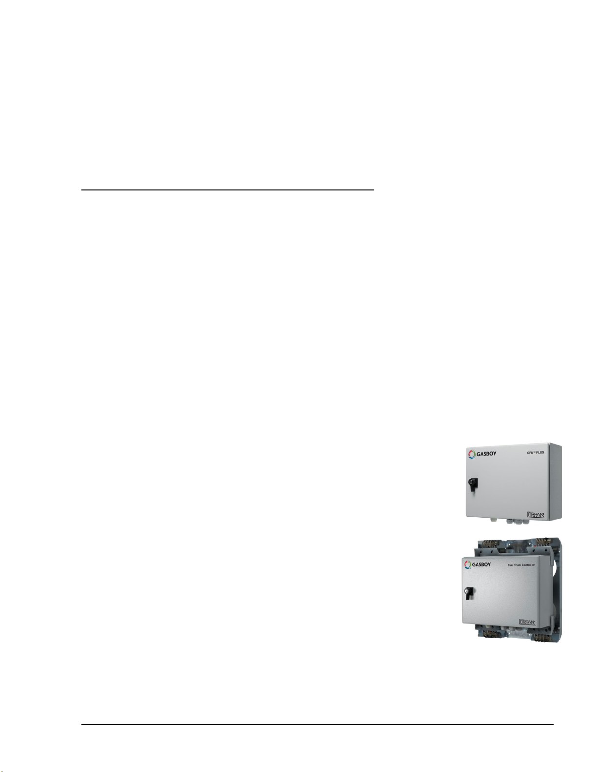
• CFN PLUS - A sealed wall-mount, complete station automation
system in one compact, durable box for internal or external
installations. It interfaces with the forecourt devices, including
dispensers, Tank Level Gauge (TLG), payment terminals and Nozzle
Readers (for optional vehicle identification)
• Fuel Truck Controller - A sealed, metal box installed on mobile
tanker trucks, Fuel Truck Controller has been especially designed to
address the heavy or stationary equipment refueling needs at the site.
Fuel Truck Controller is connected to the nozzle equipment on the
tanker truck and controls the tanker's electric valve. The heavy or
stationary equipment is identified by the Fuel Ring (Vehicle
Identification Unit) component of FuelPoint PLUS or a driver
contactless Tag
SiteOmat User’s Manual– MDE 4818
11
Page 16

1-2. SITEOMAT 1-2.1. Overview
Island Controllers are innovative products that enable refueling in Home Base Fueling Stations for
fleets' authorized vehicles or drivers. They electronically lock all dispensers and pumps thereby
ensuring that only appropriately authorized vehicles and personnel receive the required fuel. These
fuel control and data acquisition systems also ensures accurate recording of each transaction (see
Figure 1-1).
The heart of the Home Base Station solution is the SiteOmat automation software. SiteOmat runs
on an embedded operating system on the OrCU. This controller uses a solid state Flash disk and
RTC (Real Time Clock) with back-up, along with surge suppressors for transient and noise
immunity. It also includes power fail recovery mechanisms.
SiteOmat ensures accurate recording of each transaction. The dispenser is authorized to refuel after
a positive identification of the vehicle or the driver. All transaction information, including the
vehicle’s odometer or engine hour, is automatically recorded. A combined vehicle and driver
identification is also possible for a tight tracking.
SiteOmat features a comprehensive set of setup screens for easy and fast configuration and
modification in accordance with the client’s changing needs.
1-2.2. Interfaces
SiteOmat Station Controller provides the following operational features for a comprehensive Home
Base Station management:
• Supports over 50 different types of dispensers
• Advanced electronic support of electronic and mechanical dispensers
• Tank Level Gauging System (TLG) available for several brands
• Outdoor Payment Terminal and printer (OrPT)
• Contactless Tag Reader (OrTR)
• Vehicle Identification Terminals (Wireless Gateway)
• Support of large variety of communication links: cellular dial-in modem, VPN, satellite,
ADSL and more
• Interface to Head Office Systems - The system has an interface for authorization and
for sending transaction to 3rd party head office/ SiteOmat Fleet Head Office using a
single export format (Web Services).
12
SiteOmat User’s Manual– MDE 4818
Page 17
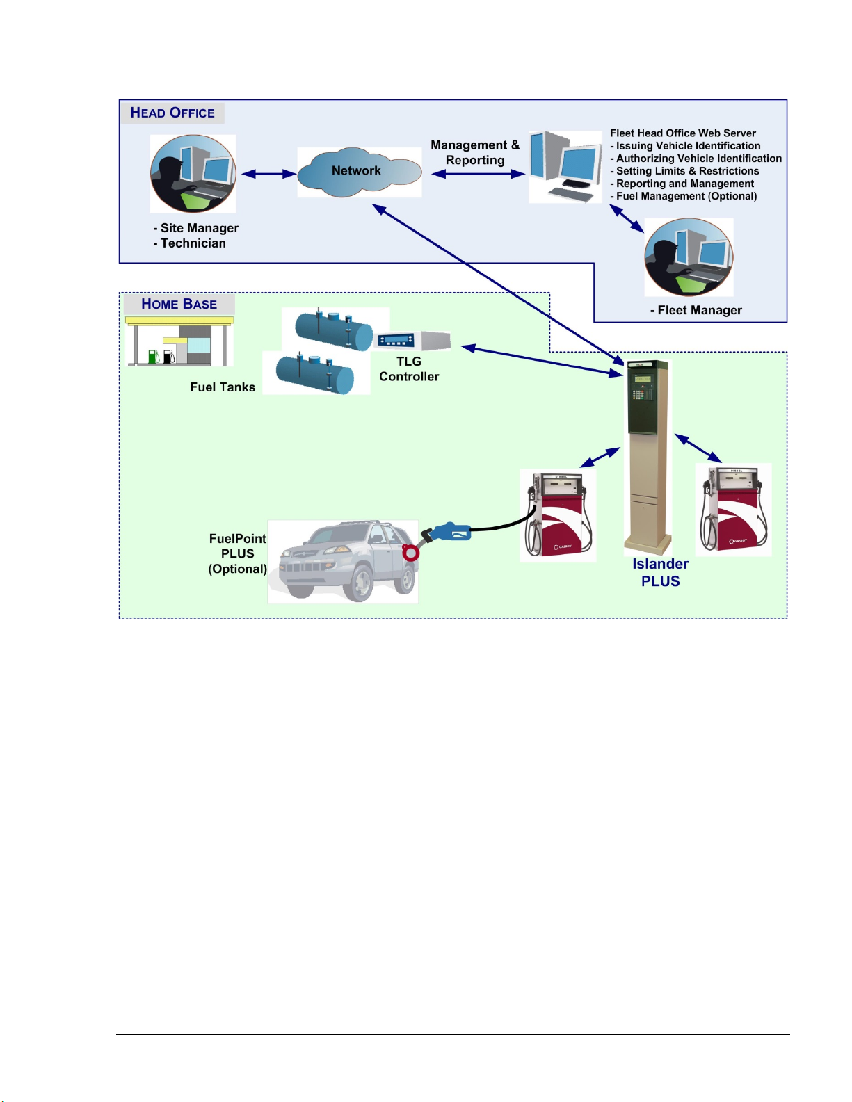
Figure 1-1 – Islander PLUS in Home Base Station - General Configuration Diagram
SiteOmat User’s Manual– MDE 4818
13
Page 18

1-2.3. Internal Communication Alternatives
OrCU can communicate with the other modules in the Island Controller system over:
a. TCP/IP Ethernet over CAT5e wires (some modules require the CommVerter Module as the
interface)
b. RS-485 links (segmentation to several links is available)
c. 8 Port CommVerter system
1-2.4. External Communication Alternatives
Communication with external management and data processing systems, for reports and
clearinghouse, can be provided by:
a. Direct - Ethernet or RS-232
b. ADSL/ISDN Modem
c. Dial-Up Modem (not recommended)
d. GPRS, Cellular modem.
1-2.5. Data Access Methods
OrCU is a web server over an SQL transaction database. It uses a secured link with several levels
of authentication. Logging into the SiteOmat is done with a standard browser from any PC and a
static IP address. Data is available in real time using pre-defined active forms.
Real-time data is available via an on-line connection, a dedicated line or Internet/Intranet (Secured)
link. The Station Controller system with SiteOmat enables real-time monitoring of a vehicle
refueling process including Volume, Price and all vehicle details.
The SiteOmat Station Controller supports exporting (transactions) and importing (Negative/Positive
lists) data using a pre-defined format.
1-3. ORCU
Orpak Controller Unit (OrCU) is a complete forecourt controller with its own embedded operating
system (see Figure 1-2). The unit consists of an embedded hardware platform with a solid state
Flash hard disk, Real Time Clock (RTC) with back up, along with surge suppressors for transient
and noise immunity. It also includes power fail recovery mechanisms.
OrCU features two separate and isolated networks (TCP/I P over Ether net) . One network l inks the
Islander PLUS syste m componen ts. The sec o nd ne t wor k is in tende d for external remote
communication (Head Office, 3rd party systems). This network is protecte d b y SSL security.
OrCU includes a Security Access Module (SAM) for enhanced data protection and safe security key
storage (Triple DES encry ptio n). OrCU includes a built-in server for Web access through Internet
Explorer 7.0 or higher.
14
SiteOmat User’s Manual– MDE 4818
Page 19
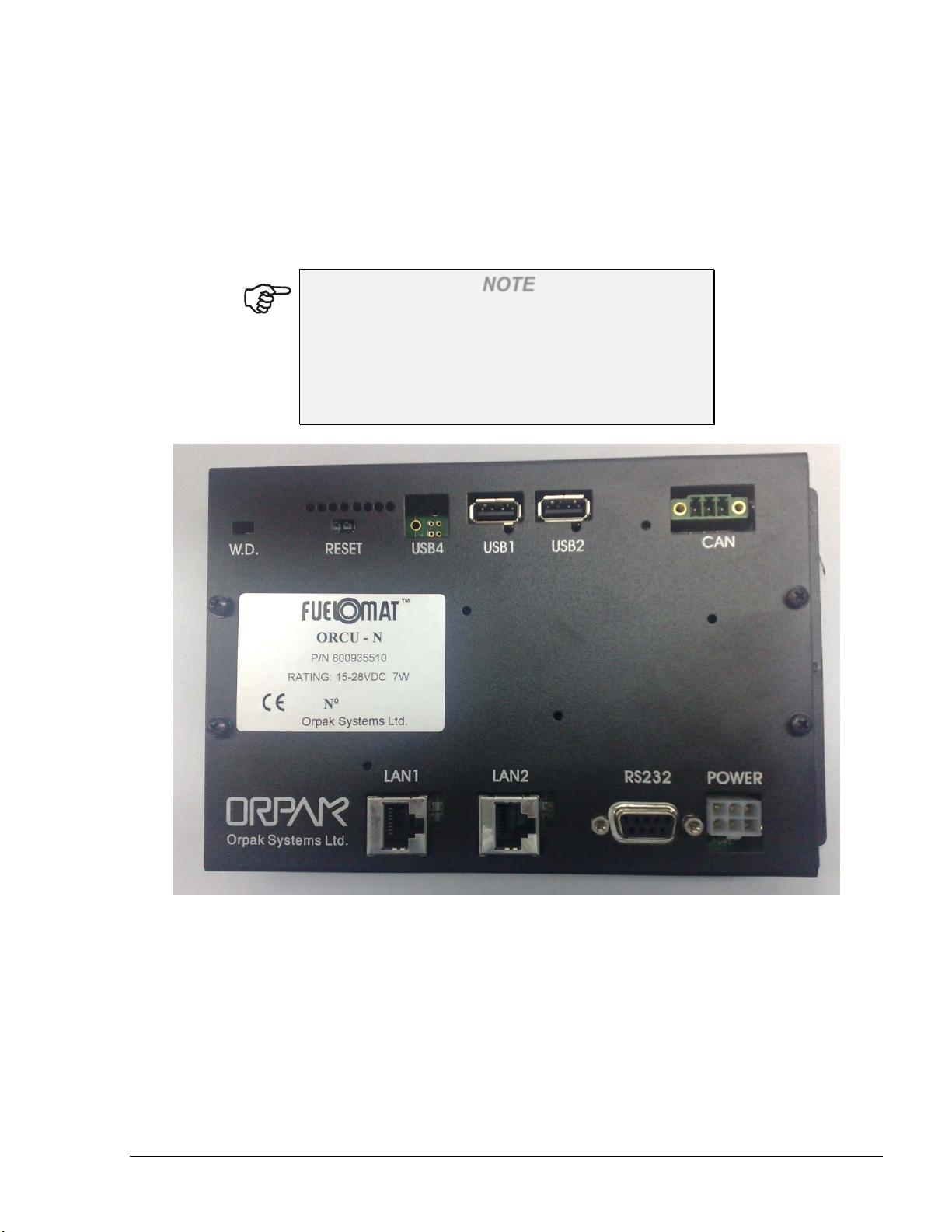
OrCU includes the following communication ports:
• LAN 1 / LAN 2 for TCP/IP over Ethernet
• RS-232 ( DB9-female ) for serial communication
• The other ports (CAN, USB) are currently not in use
NOTE
This note is relevant for the Islander PLUS system
only:
The connection (RS-485) to the optional printer is
done through the OrPT device. OrPT is connected to
the OrCU via LAN.
Figure 1-2 - OrCU - General View
SiteOmat User’s Manual– MDE 4818
15
Page 20

1-4. SYSTEM WORKFLOW – EXAMPLES 1-4.1. General
This section provides examples of different operational workflow, refueling, scenarios for selfservice at the Home Base Station. These examples are a function of the payment and transaction
devices available in each Station Controller system.
1-4.2. Refueling Scenario with FuelPoint PLUS
A motorist stops for fuel at the station. His authorization device for the fueling transaction is a
vehicle identification unit (VIU) mounted in his car. The client lifts the nozzle and inserts it into
the car’s fuel inlet.
The VIU information is automatically read and sent to the Site Controller (OrCU) for
authentication and approval. Upon approval the fueling transaction starts, once refueling is
completed, the motorist replaces the nozzle back to pump. At this point the transaction data is
kept internally. Data is periodically transferred to the Fleet Head Office (FHO) for future billing.
1-4.3. Refueling Scenario with Magnetic Cards
A motorist stops for fuel at the station. His authorization device for the fueling transaction is a
magnetic card. The client swipes the card through the magnetic card reader on the payment
terminal.
The magnetic card information is read and sent to the Site Controller (OrCU) for authentication
and approval. The client lifts the nozzle and inserts it into the car’s fuel inlet. Upon approval,
the fueling transaction starts, once the refueling is completed, the motorist replaces the nozzle
back to the pump. At this point the transaction data is kept internally. Data is periodically
transferred to the Fleet Head Office (FHO) for future billing.
During the authorization process the motorist may be prompted to enter more data to the
transaction (PIN code, Odometer, Vehicle No., Etc.). This is done by manually entering the
information using the payment terminal keypad.
1-4.4. Refueling Scenario with 2 devices (2 stage authorization)
A motorist stops for refueling at the gas station. His authorization devices for the refueling
transaction include any two devices. One represents the vehicle and the other represent the
driver (e.g. two cards, two tags, card and tag, card and manual entry, etc.). The refueling
scenario for each device is the same as with magnetic cards (see above). For each device, the
motorist may be requested to add more relevant data to the transaction (PIN for the driver,
Odometer recording for the vehicle, etc.). The OrCU opens the dispenser for refueling only after
successful authorization of the two devices.
For all options above, the motorist may print a transaction ticket from the Islander PLUS printer
(optional).
16
SiteOmat User’s Manual– MDE 4818
Page 21

1-5. MANUAL STRUCTURE
This manual comprises of the following sections:
Section 1: General Description
This section provides a general description of the FuelPoint PLUS system in general, and the
SiteOmat Station Controller in particular.
Section 2: Common Functional Principles
This section explains generic principles, which the user must be familiar with for proper operation
of the SiteOmat Station Controller application, and which will not be detailed in each occurrence.
Section 3: Getting Started
This section provides initial instructions needed for the user to start using the SiteOmat Station
Controller, namely application launch, login and general orientation of the application. This section
gives references to the following sections, which discuss the different operative parts of the
SiteOmat Station Controller.
Section 4: Monitoring Station Status
This section provides instructions for monitoring the gas station in real-time using the SiteOmat
Station Controller application. The SiteOmat Station Controller is connected to all FuelPoint PLUS
modules in the gas station, and receives on-line fueling information and status from each of the
pumps deployed in the gas station.
Section 5: Local Management
This section provides instructions for managing the fleets, devices, rules, group rules and models in
the SiteOmat Station Controller database, as well as setting limits for each vehicle per day, week,
month and year.
Section 6: Wet Stock Management
This section provides instructions for adding, controlling, tracking and updating the price of a
product in all pumps and nozzles.
Section 7: Producing Reports
This section provides instructions for generating data reports using the SiteOmat Station Controller
application.
Section 8: Events
This section provides all the events that occurred during the operation, history of login events and
reports history logs.
Section 9: Scenario in Basic Payment Modes
This section explains the basic payment modes for SiteOmat In-house.
Section 10: Glossary
This section provides a glossary of abbreviation used in the FuelPoint PLUS manuals.
Appendix A: General Guide for Web Client User
SiteOmat User’s Manual– MDE 4818
17
Page 22
This appendix provides instructions to enhance the connection from a web client to the SiteOmat
application.
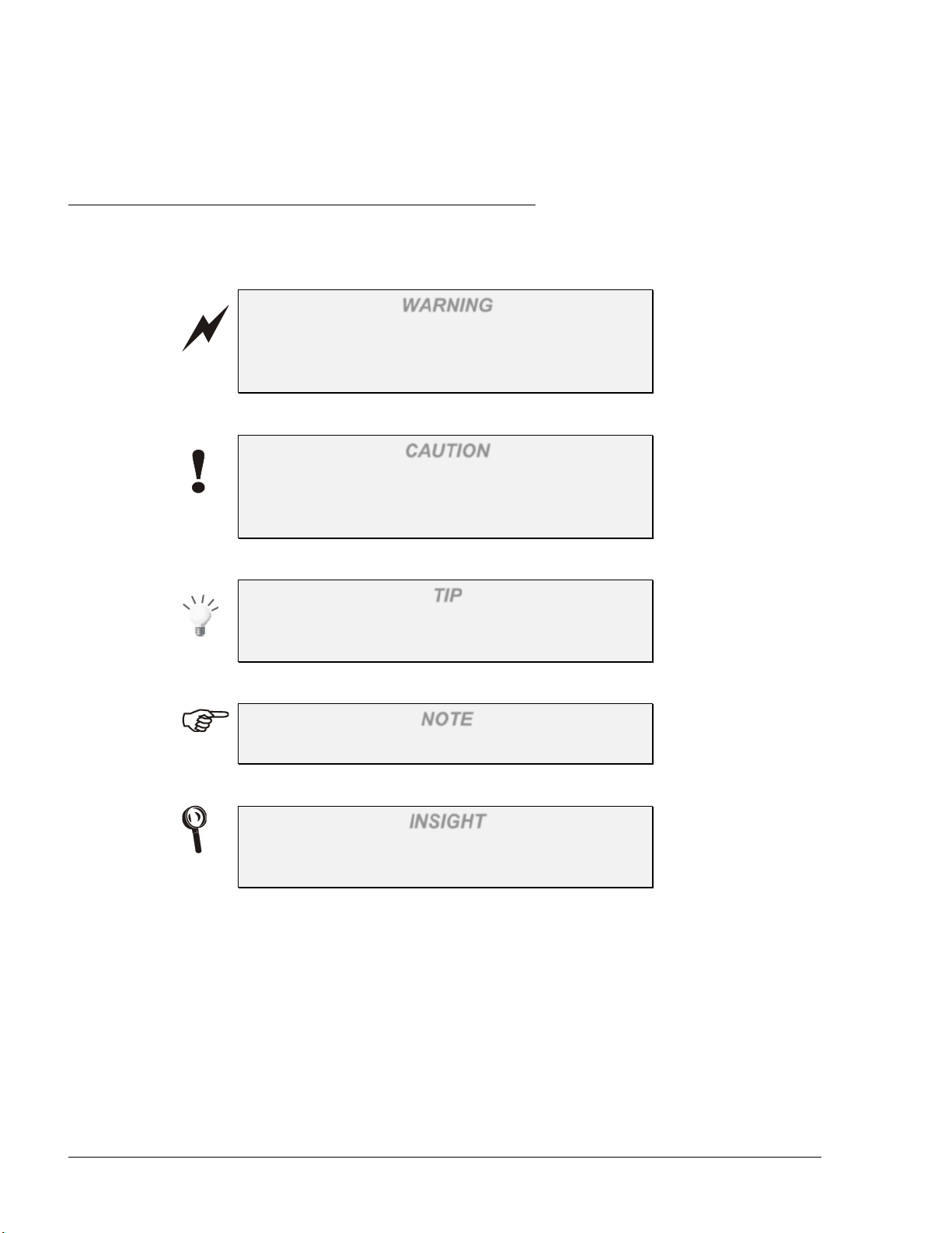
1-6. USING THIS MANUAL
This manual includes comments planted along the text, in order to draw the reader’s attention to
important issues. The comments are accompanied by symbols for ease of reference. The following
comment types are used:
WARNING
An operating procedure, practice, et cetera, which if
not correctly followed, could result in injury or loss
of life.
CAUTION
An operating procedure, practice, etcetera, which if
not strictly observed, could result in damage to, or
destruction of equipment.
TIP
A useful guidance, whose purpose is to use the
system in a more efficient way.
NOTE
A relevant and important comment.
INSIGHT
More detailed technical/ functional information
regarding relevant issues.
18
SiteOmat User’s Manual– MDE 4818
Page 23

1-7. REFERENCES
For additional and complementary information regarding Gasboy’s home base solution, please refer
to the following manuals:
• SiteOmat Station Controller Setup Manual, Document No. MDE-4817
• Islander PLUS installation Manual, Document No. MDE-4811
• CFN PLUS installation Manual, Document No. MDE-4813
• Fuel Truck Controller installation Manual, Document No. MDE-4814
• Wireless Gateway installation Manual, Document No. MDE-4815
• OrPT User’s Manual, Document No. MDE-4819
• 8-Port CommVerter User’s Manual, Document No. MDE-4820
• FHO installation and setup guide Document No. MDE-4821
• Fuel Point PLUS Installation and Configuration Manual, Document No. MDE-4851
SiteOmat User’s Manual– MDE 4818
19
Page 24
0
No.
Name
Appearance (Typical)
Description
1.
Checkbox
2.
Combo
3.
Radio
SECTION
2
COMMON FUNCTIONAL PRINCIPLES
2-1. GENERAL
This section explains generic principles, which the user must be familiar with for proper operation
of the SiteOmat Station Controller application that are not to be detailed in each occurrence.
2-2. TERMINOLOGY
The SiteOmat is a user-friendly, window-based application with a graphical interface similar to
other Windows® applications.
A number of common terms are used in this manual under the assumption that their meaning is
obvious, as depicted in Table 2-1.
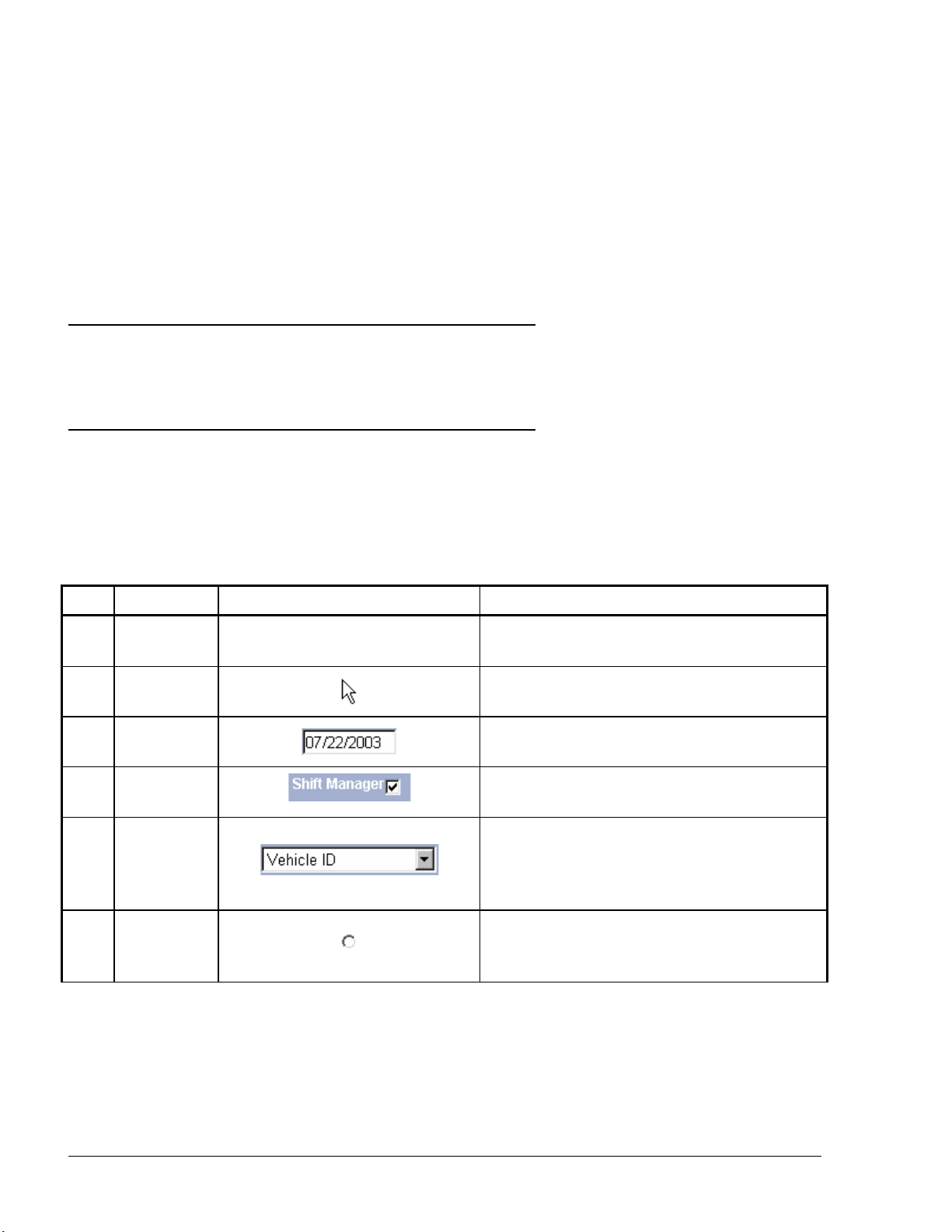
Table 2-1. Common Terms
1.
2.
3.
Cursor
Pointer
Text Box
Box
Buttons
|
Indicator pointing where text is to be
inserted
Indicator pointing where the mouse is
located on the screen
An element allowing the user to input text
information
An element permitting the user to enable/
disable a specific option.
An element allowing the user to choose one
value from a list. Clicking on the arrowshaped button in the combo box opens the
list of values.
An element allowing the user to choose a
single value from a predefined set of
options.
20
SiteOmat User’s Manual– MDE 4818
Page 25
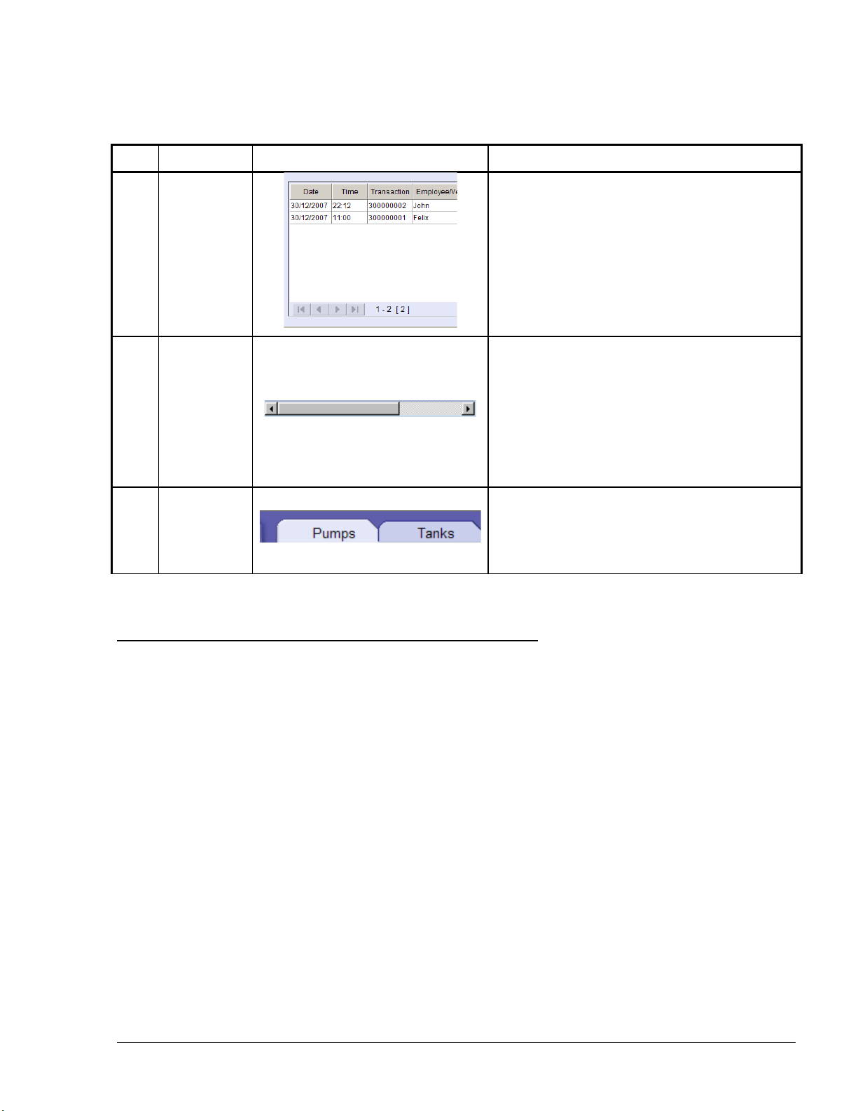
Table 2-1. Common Terms
No.
Name
Appearance (Typical)
Description
4.
Grid
5.
Scroll Bar
6.
Tab
An element, usually located on the top of a
A database consisting of columns (fields)
and rows (records). Grids are a common
way of displaying and handling data in the
SiteOmat application.
A bar allowing continuous text to be
viewed even if it does not fit into the space
in the window. Clicking the arrow-shaped
buttons in the ends allows users to move the
body of the document.
Scroll bars may be either horizontal or
vertical.
window, allowing the user to switch from
multiple documents located in a single
window.
2-3. COMMON ACTIONS
The user-interface of the SiteOmat Station Controller is intuitive and requires little experience for
using it. The operative actions are common and generic across the various windows. The common
actions in the SiteOmat application are as follows:
a. Selecting a row in a grid
b. Marking row(s ) in a grid
c. Sorting a grid
2-3.1. Selecting a Row in a Grid
Selecting a row in a grid serves several purposes, such as displaying the data associated with the
grid. To select a row, click on the applicable row. Consequently, the row is highlighted in a gray
color (as seen in Figure 2-1), indicating that the row is currently selected.
SiteOmat User’s Manual– MDE 4818
21
Page 26
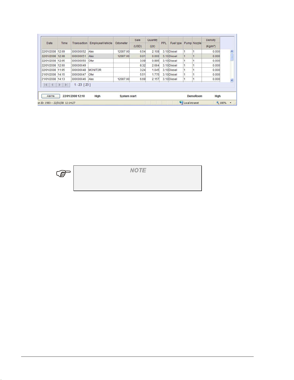
Figure 2-1. Selecting a Row in a Grid
2-3.2. Sorting a Grid
Sorting a grid is done simply by clicking on a column header. The records are consequently sorted
by the selected column in an ascending order. A second click arranges the records by descending
order. The small triangle in the right-side of the selected header indicates the current sorting order.
NOTE
Sorting applies only to the currently displayed
screen.
22
SiteOmat User’s Manual– MDE 4818
Page 27
SECTION
3
GETTING STARTED
3-1. GENERAL
This section provides initial instructions needed for the user to start using the SiteOmat, namely
launching the application, login and familiarizing with the general orientation of the application.
This section provides references to the subsequent sections, which discusses the different operative
parts of the System.
NOTE
The SiteOmat application has been designed and
tested to run properly on Microsoft Internet Explorer
7 and up. On any other browser (or version), the
application may not function properly.
3-2. SITEOMAT STARTUP
The SiteOmat Application can be logged into using a standard browser from any PC. The
application is launched from the SiteOmat computer and may be accessed from any networked
computer (directly connected to the SiteOmat via the LAN) or from a remote computer with an
Internet browser over the Internet.
To access the application, launch the Internet browser and enter the address (IP address or domain
name) of the SiteOmat as provided by Gasboy as follows:
https://IPaddress
(Each customer’s IP address may differ based on their network.)
NOTE
Before proceeding, go to Appendix A, and follow
the procedure. This enables the connection from a
web client to the SiteOmat and improves browsing
capabilities.
SiteOmat User’s Manual– MDE 4818
23
Page 28
Once a link is established, the SiteOmat login window is displayed. The system grants access to
authenticated users only. It sets its clearance level in accordance with the organizational level of
the user. Information regarding the login is given in the following paragraph.
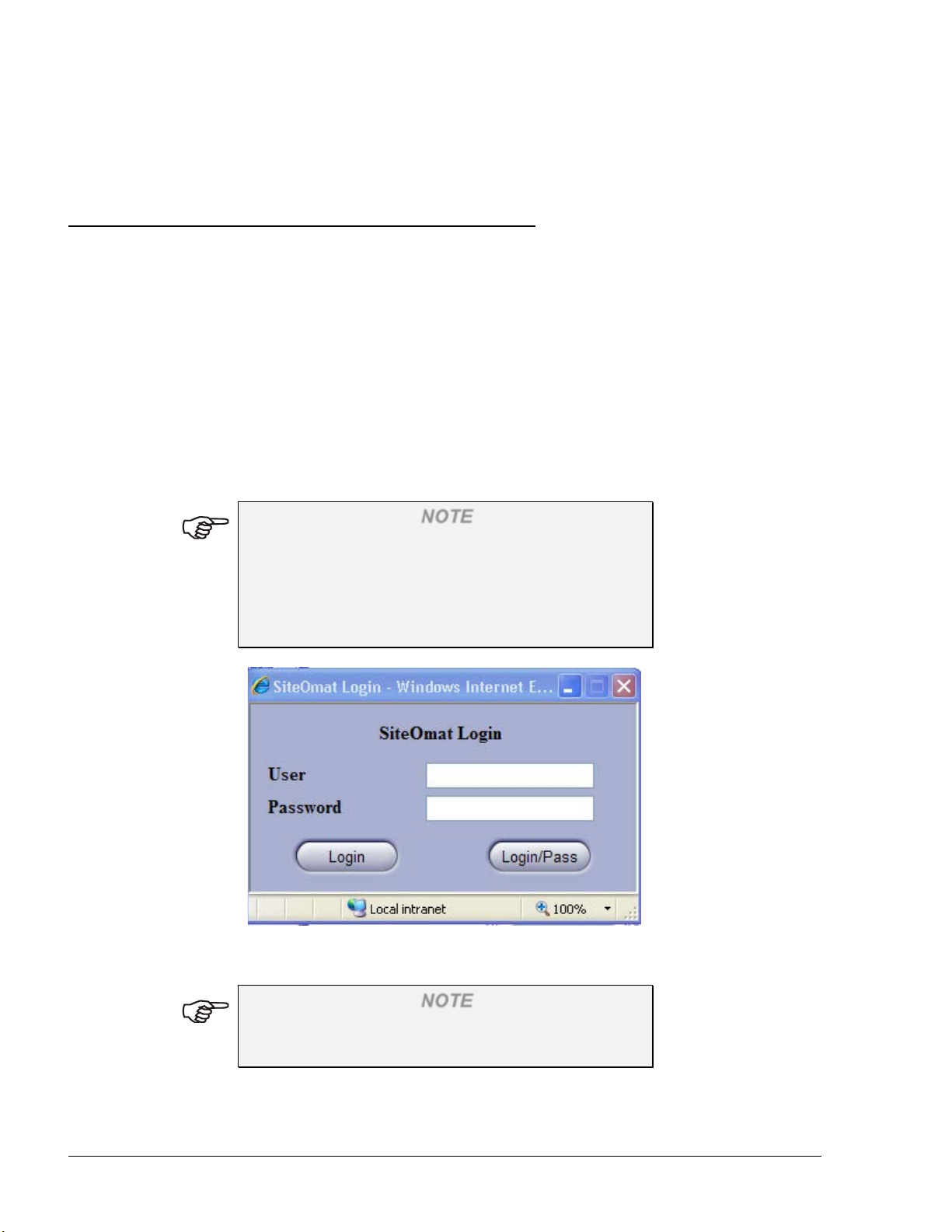
3-3. LOGIN
The SiteOmat Station Controller incorporates powerful SSL mechanisms to allow only authorized
users to view and alter its contents. The SiteOmat application opens with a login dialog box, for
entering the username and password (see Figure 3-1).
The accessible contents and privileges of the user depend upon its clearance level, as set in the User
Management definitions of the SiteOmat application (refer to Section 5 – Local Management). The
application is designed to grant each user with his suitable privileges and block other capabilities.
For example, a gas station manager is not allowed to manage vehicle fleets.
Enter the username and password and click on the Login button. The SiteOmat Station Controller
checks the entered information against the users listed in the system. If the user and the password
are authenticated, the user logs into the SiteOmat Station Controller with its applicable clearance
level.
NOTE
The default username is “Admin” and password is
“Admin” (lowercase sensitive).
It is highly recommended for the administrator to
change the password once the system is running (the
user "Admin" cannot be deleted or renamed).
Figure 3-1. SiteOmat Login Dialog Box
NOTE
Disable any sort of pop-up blockers, because it
interferes with the operation of the application.
24
SiteOmat User’s Manual– MDE 4818
Page 29
3-4. NAVIGATING THROUGH THE SITEOMAT
Button
Description
After successful login, the opening screen (see Figure 3-3) appears. When entering the program for
the first time, the opening screen appears after the system data is uploaded (it may take a few
seconds). Meanwhile the following message appears (see Figure 3-2):
Figure 3-2. Updating Data Message
The SiteOmat interface includes three sections:
a. Navigation Bar – Accessing the various capabilities of the SiteOmat application is done using
the Navigation Bar on the left-hand side of the window. The Navigation Bar appears throughout
the SiteOmat application and contains buttons, which lead to the various screens of the
application within the boundaries of the user’s clearance level
b. Alarm Line– The alarm line is constantly displayed on the bottom of the window, indicating
the most critical fault in the system
c. Work Area – The main user interface located in the center of the screen
NOTE
The login name of the current user is displayed in
the information bar at the bottom of the screen
"Login User Name" (see Figure 3-3).
Clicking on a button in the Navigation Bar opens the subsequent contents in the work area; while
the Navigation Bar is fixed, the work area is dynamic and changes according to the requested
option. The objective of each button in the Navigation Bar is depicted as follows (see Table 3-1):
Table 3-1. Navigation Bar Buttons
SiteOmat User’s Manual– MDE 4818
25
Page 30
Status
Enables real-time monitoring of the gas station fuel pumps. This part is
Reports
A report generator tool, which facilitates producing a wide variety of reports
Wet Stock Mgmt
Manages and updates the price of a product in all pumps and nozzles
Local
Management
Defines all authorized fleets and devices in the tank-fuel station
Setup
Leads to SiteOmat setup definitions, which map the gas station for the
Event Viewer
Enables viewing system warnings and logins.
Admin
The admin section contains system properties and diagnostics tools, meant for
Exit
Closes the current window and opens the login dialog - Used for exiting the
detailed in Section 4 – Monitoring Station Status
on the data in the SiteOmat
including a product price history report for tracking price changes
SiteOmat Station Controller. These definitions are beyond the scope of the
user, and are described in the SiteOmat In-House Installation & Setup
Manual
the SiteOmat Controller administrator/technician.
SiteOmat Application.
NOTE
Not all navigation buttons are available to all users
(i.e. Setup and Admin navigation buttons are
available to users with ADMIN clearance level
only).
26
SiteOmat User’s Manual– MDE 4818
Page 31

Figure 3-3. SiteOmat Opening Screen
SiteOmat User’s Manual– MDE 4818
27
Page 32

4
SECTION
MONITORING STATION STATUS
4-1. GENERAL
This section provides instructions for monitoring the gas station in real-time using the SiteOmat
application. The SiteOmat Station Controller is connected to all FuelPoint PLUS modules in the
gas station, and receives on-line fueling information and status from each of the pumps deployed in
the gas station. The Status feature also enables monitoring the status of the fuel tanks in the station.
4-2. STATION MONITORING
Enter the station-monitoring window by clicking on the Status navigation button on the SiteOmat
Navigation Bar. This section is divided into four sub-sections which are accessed through the
following tabs: Pumps, Tanks, OrPT, and Devices, as seen in Figure 4-1
28
SiteOmat User’s Manual– MDE 4818
Figure 4-1. Status – Pumps Screen
Page 33

4-3. PUMP STATUS
The application presents the data received from each of the fuel pumps in the station, as seen in
Figure 4-2.
The station-monitoring window, aside from displaying an overall picture regarding the fuel
dispensing activity in the gas station, also allows users to remotely initiate a fuel dispensing
transaction, by clicking on the applicable pump head indicator or stops the fuel dispensing
transaction, by clicking the emergency stop icon on the right side.
Figure 4-2. Station Monitoring – Pump Status View
In order to display information in a readable size, the Pump Status window enables monitoring a
group of eight pump heads simultaneously. Switching between the groups of pump heads is done
by clicking on the gauges in the upper part of the window.
NOTE
A pump may consist of one or two pump heads, each
pump head including a number (one or more) of
nozzles. Only a single nozzle in a pump head can be
used in a given time.
4-3.1. Pump Status Window Elements
The Status window comprises several elements, each serves a different role in the monitoring of the
gas station, as follows:
a. Pump Heads Gauge × 4
SiteOmat User’s Manual– MDE 4818
29
Page 34

b. Pump Head On-Line Data × 8 for each group (total of 32)
c. Fueling Transactions History Log
4-3.1.1. Pump Heads Gauge
The four Pump Heads Gauges (see Figure 4-2) serve two functions:
a. Switching between the four groups of eight pump heads, by clicking on the applicable
gauge:
1. First (leftmost) Gauge: Pump heads 1 to 8
2. Second Gauge: Pump heads 9 to 16
3. Third Gauge: Pump heads 17 to 24
4. Forth Gauge: Pump heads 25 to 32
b. Indicating whether a fueling transaction is currently performed in one of the pump heads.
The gauge contains eight indicators, each representing a pump head (the leftmost is the first
pump head in the group and the rightmost is the last one). The color indications are as
follows:
1. Gray: No pump head is assigned to the indicator
2. Blue: The pump head is Idle – awaiting fueling request
3. Yellow: The pump head is in Call status – the fuel nozzle was lifted
4. Purple: The pump head is in Ready status – fueling was authorized but the
nozzle was not lifted yet
5. Green: The pump head is in In-Use - fuel is being dispensed; or Pay status -
the transaction is completed and the transaction is being charged
6. Orange: Fueling was stopped (e.g.: fuel limit is reached, or fueling is stopped in
automatic fueling, in cases where the nozzle was taken out of the vehicle fuel inlet
during the fueling)
7. Red: A problem of some sort occurred (i.e. error in pump, communication
error)
NOTE
The color indicators display the status of all the
pump heads, even though the Status window only
shows eight pump heads each time.
4-3.1.2. Pump Head On-Line Data
30
SiteOmat User’s Manual– MDE 4818
Page 35

The Pump Head On-Line Data is displayed in five text boxes and two indicators. The fueling
process is viewed in real-time, as if watching the display on the fuel pump. The textual information
displayed on-line is as follows:
a. USD: The amount of money, which should be collected for the fuel dispensed so
far
b. Gallon: The fuel volume dispensed so far
c. Emp/Veh: The Employee name or plate number of the vehicle being fueled
d. Nz: The number of the nozzle dispensing the fuel
e. Fleet: The number of the fleet, to which the fueled vehicle belongs
4-3.1.2.1. Pump Head Indicator
The pump head indicator displays the number of the pump head. The following states are displayed
by the pump head color indicator:
Red: The pump head is not defined
Green: The pump head is monitored
Black: The pump head is blocked (deactivated)
4-3.1.2.2. Nozzle Indicator
The nozzle indicator displays the state of the nozzle of each pump head. The nozzle icon changes
according to the nozzle state, as follows:
a. Idle – awaiting fueling request
b. Call status – the fuel nozzle was lifted
c. In-Use – fuel is being dispensed
d. Pay status – transaction is completed and money is collected
e. Ready – fueling was authorized but the nozzle was not lifted yet
f. Stop – Fueling is stopped (e.g. nozzle is pulled out before fueling was completed)
g. Attention – A problem of some sort occurred (i.e. pump in error, communication error)
SiteOmat User’s Manual– MDE 4818
31
Page 36

4-3.1.3. Fueling Transactions History Log
2.
Time
Time of the transaction
4.
Employee/Vehicle
The license plate number of the fueled vehicle. The vehicle number
9.
Fuel type
Type of fuel supplied in the transaction
11.
Nozzle
Number of the nozzle in the pump head, used to supply the fuel in
The Fueling Transactions History Log is a grid listing all the fueling transactions that took place in
the gas station.
The grid is sorted by the date and time of the transaction, so the most recent transaction appears
first. However, the grid may be sorted by any other field (see paragraph 2-3.2). The fields
appearing in the Fueling Transactions History Log are described in Table 4-1.
Table 4-1. Fueling Transactions History Log Fields
No. Field Name Description
1. Date Date of the transaction
3. Transaction A unique transaction ID ordinal number given by the SiteOmat
Station Controller to each transaction
appears in the transaction only if provided from the Fuel Ring or
entered by the authorizer in the OrPT
5. Odometer Odometer reading of the vehicle in the transaction
6. Sale (USD) The sum of money collected in the transaction
7. Quantity (Gallons) The fuel volume dispensed in the transaction
8. PPV Price Per Volume (PPV) i.e the ratio between the Gallon value and
the Amount value.
10. Pump Number of the pump head, from which the transaction was
performed
the transaction
12. Density (Kg/m3) Fuel density
32
SiteOmat User’s Manual– MDE 4818
Page 37

4-4. REFUELING THROUGH SCREENS
The SiteOmat Controller enables users to remotely initiate and stop refueling transactions. The
start/stop refueling is done through the Status window (see Figure 4-2), by click on the pump head
icon, from which the refueling transaction should be performed.
NOTE
The remote refueling option is available only if
enabled in the setup of the SiteOmat Controller. For
more information about the setup of this feature,
refer to the SiteOmat In-House Installation &
Setup Manual.
4-4.1. Starting Refueling
To start a refueling transaction from a certain pump head, click on the applicable pump head icon in
the Status window. The SiteOmat presents a confirmation box, as seen in Figure 4-3.
Figure 4-3. Start Refueling Confirmation Message
In cases where the pump head is currently occupied with a refueling transaction, a proper
notification message is displayed (see Figure 4-4).
Figure 4-4. Pump Busy Message
In cases where the pump head is available for refueling, the SiteOmat prompts for the money or
volume limit for the requested refueling, as seen in Figure 4-5. Enter the applicable money/volume
value and click Money or Volume, accordingly.
SiteOmat User’s Manual– MDE 4818
33
Page 38

Figure 4-5. Authorize Pump Dialog Box
The SiteOmat requests confirmation for the given money/volume amount (see Figure 4-6 and
Figure 4-7). Confirming the limit starts the refueling transaction for the given pump.
Figure 4-6. Money Limit Confirmation Message
Figure 4-7. Volume Limit Confirmation Message
4-4.2. Stopping Refueling
All pump heads currently engaged in a refueling transaction can be remotely stopped through the
Pump Status window of the SiteOmat Controller. Click on the emergency stop icon at the
middle-right side of the Pump Status window to stop all current refueling transactions.
A confirmation box is displayed prior to actually stopping the refueling.
34
SiteOmat User’s Manual– MDE 4818
Page 39

Figure 4-8. Close All Pumps Confirmation Message
SiteOmat User’s Manual– MDE 4818
35
Page 40

4-5. TANK STATUS
The Tank Status window (see Figure 4-9) is accessed by clicking the Status navigation button, then
clicking the Tanks tab. This window enables visual inspection of the current fuel level in each
tank. The visual and textual data displayed for each tank is obtained from the last inventory
measurement (for details, refer to the Wet Stock management in Section 6 ), without the fuel
consumption according to the registered transactions. This data can also be provided from the TLG
readout.
Figure 4-9. Station - Tanks Screen
In order to display information in a readable size, the Tanks Status window enables monitoring a
group of four tanks simultaneously. Switching between groups of tanks is done by clicking on the
gauges in the upper part of the screen.
4-5.1. Tank Status Window Elements
The Status window is comprised of several elements, each serving a different role in the gas station
monitoring as follows:
a. Tanks Gauge × 6
b. Tanks On-Line Data × 4 for each group (total of 24)
c. Capacit y Trans acti on s Hist ory Log.
36
SiteOmat User’s Manual– MDE 4818
Page 41

4-5.1.1. Tanks Gauge
The four Tanks Gauges (see Figure 4-9) have two functions:
a. Switching between the four groups of eight Tanks, by clicking on the applicable gauge:
1. First (leftmost) Gauge: pump heads 1 to 4
2. Second Gauge: pump heads 5 to 8
3. Third Gauge: pump heads 9 to 12
4. Forth Gauge: pump heads 13 to 16
5. Forth Gauge: pump heads 17 to 20
6. Forth Gauge: pump heads 21 to 24
b. Indicating whether a fuel tank is currently specified. Each of the gauges contains four
indicators, each representing a tank (the leftmost is first tank in the group and the rightmost
is the last one). The color indications are as follows:
1. Gray: No tank is assigned to indicator
2. Blue: The tank is Idle
4-5.1.2. Tank Head On-Line Data
The Tank On-Line Data is displayed in six text boxes and a single indicator. The tank fuel volume
is displayed in real-time. The textual information displayed online is as follows:
a. Fuel Level: Displays the height of fuel in the tank
b. Fuel Volume: The fuel volume remained so far
c. Water Level: Displays the height of the water in the fuel tank
d. Temp: Displays the temperature inside the fuel tank
e. Density at 150C: Displays the fuel density in kg/m3 at this temperature
f. Flow Rate: Flow rate calculated over a period of time as defined in the setup. The units
are volume per hour, and it is based on two measurement points over the
defined period. A negative value indicates level drop
SiteOmat User’s Manual– MDE 4818
37
Page 42

Some of the data may not be available depending on the TLG type and probes (such as density).
2.
Capacity
Product capacity
If the TLG reports on delivery status, a relevant indication appears.
4-5.1.2.1. Tank Indicator
The tank's fuel indicator indicates whether the tank fuel is currently specified. The following states
are shown by the fuel tank indicator:
a. Green: Displays the tank fuel volume
b. Red: Displays the water level in the tank. If the water level is above zero, at least one
red line is displayed
4-5.1.3. Fuel Tank Transactions History Log
The Fuel Tank Transactions History Log is a grid listing all the fuel tanks transactions that took
place in the gas station.
The grid is sorted by product. However, the grid may be sorted by any other field (as instructed in
page 22 – Sorting a Grid). The fields appearing in the Fuel Tank Transactions History Log are
described in Table 4-2.
Table 4-2. Fuel Tank Transactions History Log Fields
No. Field Name Description
1.
3.
Product Fuel type name
Volume Volume of all the tanks containing the specific product in the gas
station
38
SiteOmat User’s Manual– MDE 4818
Page 43

4-6. ORPT STATUS
The application presents the display of the OrPT as seen in Figure 4-10.
The OrPT status screen allows users in the back/head office to view the information currently
displayed on any of the OrpT defined in the system.
NOTE
The current message displayed on the selected OrPT
is displayed. Data entered by drivers/attendants
(such as odometer) is not displayed in this screen.
Select the OrPT to be displayed utilizing the adjacent drop-down list.
The screen can be refreshed manually, by clicking on the Refresh button, or automatically by
selecting the Auto refresh checkbox and defining the refreshment intervals from the Refresh every
x sec drop-down list.
Figure 4-10. Station Monitoring – OrPT Status View
SiteOmat User’s Manual– MDE 4818
39
Page 44

4-7. DEVICE STATUS
1.
Name
Name of the device
3.
Status
Status of the device as shown in the alarms
The application presents a summary of all the devices and their current status in the system as seen
in Figure 4-11.
Figure 4-11. Status– Devices Screen
All the information is taken from the alarm and the pump current status.
The devices are shown over a grid, divided into three columns as described in Table 4-3.
Table 4-3. Devices Status
No. Field Name Description
2. Type Type of the device
40
SiteOmat User’s Manual– MDE 4818
Page 45

SECTION
5
LOCAL MANAGEMENT
5-1. GENERAL
This section provides instructions for managing the fleets, vehicles, devices and defining them with
rules and information in the SiteOmat Station Controller database. Upon insertion of a fuel nozzle
to the vehicle’s fuel inlet, the reader (wired or wireless) reads the Fuel Ring information, decrypts
the encrypted string from the Fuel Ring and the string is sent to the SiteOmat. The SiteOmat then
compares the vehicle’s information against a negative or positive list on-line from the host
computer or in the local lists. Only after the vehicle information is authenticated, the SiteOmat
allows fueling.
Another means of automatic payment is the smart keys, which bear the user’s information in an
encrypted string. A smart key, held close to the Key Reader (an OrPT accessory), is read by the
Key Reader and the information is sent to the SiteOmat System Controller for authentication.
The SiteOmat application enables adding/removing and updating fleets and their vehicles, and
activating (fueling allowed) or blocking (fueling denied) fleets/vehicles. Management of the fleet
and vehicle lists is done by clicking on the "Local Management" button in the Navigation Bar, and
described in the following paragraphs.
The same screens that are defined in this section are used in the SiteOmat Head Office for Fleet
Management. Some of the defined fields are applicable in the Head Office for various reports such
as consumption.
NOTE
Local fleets and devices are allowed to refuel only in
the stations where they are defined. In a system with
several stations, use Head Office or Magic to
globally define the same rules and information.
5-2. LOCAL MANAGEMENT OVERVIEW 5-2.1. Devices Definition
A device in the SiteOmat system is a physical authorization device such as Fuel Ring (Vehicle
Identification Unit), tag, key or magnetic card. A keypad entry is also a device. All devices are part
of a department because a department is part of a fleet.
In order to refuel, an authentication device should be recognized by the SiteOmat. Once the reading
and parsing of the device string are done, a search for a match is executed in the SiteOmat database.
SiteOmat User’s Manual– MDE 4818
41
Page 46

SiteOmat includes lists of fleets, and each fleet has a list of vehicles with their authentication
devices.
A set of rules are set for each device to check if the device is allowed to fuel under the current
conditions. Fleet lists (the vehicles) can work in two modes:
• Positive list (preferred method):
Only vehicles found in the list can refuel and in addition, each vehicle must meet a set of
rules
• Negative list:
All vehicles in this fleet can refuel except the ones that are in the negative list
Positive/Negative lists apply only to the department level of a fleet, and not to the fleet itself. There
can be only one department classified as a negative list in a fleet.
Each fleet has a set of rules that are defined as default rules for each vehicle. It is possible to
change the rule per vehicle. If the fleet list is defined as negative, then the fleet rules are used for
each vehicle that is not in the list. This allows global restrictions on a fleet without the need to set
boundaries for each vehicle.
Rules templates are defined and can be used for fast and global definition of authorization. A fleet
or vehicle can be set to comply with any of these rules templates. If the rule template is changed, it
affects any device associated with it.
5-2.2. Workflow
Creating Models, Rules and Group Rules are preliminary stages of setting fleet definitions. See
paragraphs 5-3 and 5-4 below for models and rules creation and paragraphs 5-6, 5-7 and 5-8 for
fleet, department and devices definition respectively.
Define fleets, then departments and finally the various devices.
A device pertains to a department which is part of a fleet. A new rule created for and imposed to a
fleet, is inherited by its new subordinate departments and therefore by the devices related to the
department. Even though, the rule can be overridden at the lower levels (a specific
Device/Department can be defined oppositely to the fleet rule.)
5-3. DEFINING VEHICLE MODELS 5-3.1. General
Defining vehicle models is not a mandatory stage in the vehicle management process, yet it is
meant to ease the task of defining the vehicles at a later stage. When defining vehicle models, the
type and manufacturer are provided. Also their tank capacity and standard fuel consumption are
specified. Later, when defining a vehicle, selecting its model from a list automatically fills in this
information.
5-3.2. Vehicle Models Screen
To open the Vehicle Model screen (see Figure 5-1):
1. Click on the Local Management navigation button (see Figure 7-1)
42
SiteOmat User’s Manual– MDE 4818
Page 47

2. Select the Models tab
Figure 5-1. Local Management Models Main Screen
NOTE
The information in the figure above is for example
purposes only, and does not reflect the actual
information of the specified vehicle models.
5-3.3. Defining a New Model
Unless models database was imported, the models grid is empty. To define a new vehicle model,
proceed as follows:
1. Click on the New button
2. The Model Properties dialog box appears (see Figure 5-2)
SiteOmat User’s Manual– MDE 4818
43
Page 48

Field
Description
Make
Vehicle's manufacturer
Model
Vehicle's model
Description
General description
Class
Additional description
Tank Capacity
Vehicle's tank capacity
Standard Odometer Consumption
Vehicle's average fuel consumption
Standard EH Consumption
Vehicle's average fuel consumption per engine
Figure 5-2. Model Properties Dialog Box
NOTE
The information in the figure above is for example
purposes only, and does not reflect the actual
information of the specified vehicle models.
Proceed as follows:
1. Fill in the model characteristics in the applicable fields (see Table 5-1). All fields are
mandatory.
Table 5-1. Model Properties Fields
44
SiteOmat User’s Manual– MDE 4818
hour
Page 49

2. Click OK & New to save the definition and define another model
3. Click OK to save changes and close the dialog box, or
4. Cancel to close the dialog box without saving the changes
5-3.4. Modifying a Model Properties
The Local Management Models screen enables users to view/modify the model properties.
Proceed as follows:
1. Select a model by double-clicking a row in the grid of the Local Management Models screen
(see Figure 5-1); the Model Properties dialog box appears (see Figure 5-2)
2. Modify the model characteristics in the applicable fields
3. Click OK to save changes and close the dialog box, or
4. Cancel to close the dialog box without saving the changes
5-3.5. Deleting a Model
To delete an existing vehicle model, proceed as follows:
1. Select a model by clicking a row in the grid of the Local Management Models screen (see
Figure 5-1)
2. Click on the Delete button
3. The Delete procedure requires approval to implement the action
4. Click OK
SiteOmat User’s Manual– MDE 4818
45
Page 50

5-4. DEFINING RULES
The rules, defined in the Local Management section, are the means by which the vehicle refueling
is limited. The SiteOmat System offers a comprehensive mechanism of limit definition.
The rules defined in this section are individual units, which, in effect, are not applied directly to a
fleet/department/vehicle. Instead, once defining the rules, the user creates group rules (described in
detail in paragraph 5-5) that consist of a number of rules. These group rules are then imposed on
the fleet/department/vehicle to limit refueling.
To enter the Rules screen (see Figure 5-3), click on the Local Management navigation button, and
select the Rules tab. As in other data-bound screens, the Rules main window consists of a grid
listing the existing rules, and several action buttons. Each row in the grid describes the rule name,
type, description and the contents of the rule, as well as the fleet.
The following rule types are available:
a. Time Range: Defines the days and times (within each day), during which the vehicle may
refuel
b. Limits: Defines fuel limits per day/week/month, set in money/volume, for the device
c. Visits: Specifies the maximum number of visits to fuel stations allowed for the
vehicle per day/week/month/year
d. Fuel: Limits the refueling vehicle to certain types of fuel.
46
SiteOmat User’s Manual– MDE 4818
Page 51

Figure 5-3. Rules Main Screen
5-4.1. Creating a New Rule
To create a new rule, follow the instructions below:
1. Click on the New button on the Local Management Rules screen
2. The Rule Properties window appears (see Figure 5-4). The New Rule window consists of
two tabs: General and Detail. While the General tab is fixed, the contents of the Detail tab
changed depending upon the selected rule type
3. Select the desired rule type from the drop-down list
4. Enter a descriptive name and a description for the rule
5. Select the Detail tab. The Detail tab for each rule type is described in the following
paragraphs:
• Time Range Rule - Paragraph 5-4.1.1
• Limits Rule - Paragraph 5-4.1.2
• Visits Rule - Paragraph 5-4.1.3
• Fuel Rule - Paragraph 5-4.1.4
SiteOmat User’s Manual– MDE 4818
47
Page 52

Figure 5-4. Rule Properties Screen
5-4.1.1. Time Range Rule
The Time Range rule is meant to limit vehicle refueling to specific days and periods during the day.
By applying this rule to a vehicle, it can only refuel in the specified times.
If the selected rule type in the Rule Properties screen (see Figure 5-4) was Time Range, the Detail
tab displays the information shown in Figure 5-5.
48
SiteOmat User’s Manual– MDE 4818
Page 53

Figure 5-5. Time Range Rule Detail Tab
To define the Time Range rule:
1. Select whether to allow or ban refueling in the time ranges to be defined
2. Click the check-boxes adjacent to the days in which refueling is to be allowed/disallowed, or
click on the Set All button to mark all days
3. By default, selecting a certain day allows/disallows refueling during the entire day, from
00:00 to 23:59. To change the time within a certain day, click on the Time button adjacent
to the day
4. The Rule Time Range dialog box appears (see Figure 5-6)
5. Define the desired time range (from HH:MM to HH:MM)
6. Click Add to define another time range
7. Clicking on the Delete button adjacent to a time range row deletes that time range
8. Once defining all time ranges, click OK to save changes and close the window
9. Repeats steps 3 to 8 for all the days, in which the time ranges are to be defined
10. Click OK to save changes and close the window
SiteOmat User’s Manual– MDE 4818
49
Page 54

Figure 5-6. Rule Time Range Dialog Box
5-4.1.2. Limits Rule
The Limits rule defines fuel limits per a single refuel or per day/week/month, set in money or in
volume, for the fleet/department/vehicle.
If the selected rule type in the Rule Properties screen (see Figure 5-4) was Limits, the Detail tab
displays the information shown in Figure 5-7.
NOTE
The limits per day/week/month/year can only be
applied to departments classified as positive lists.
The reason is that a negative list restricts the devices
associated to it ad-hoc, and does not reference any
information, as the amount of credit used, regarding
the devices.
50
SiteOmat User’s Manual– MDE 4818
Page 55

Figure 5-7. Limits Rule Detail Tab
To define the Limit rule:
1. Select whether the limits to be defined refer to Money or to fuel Volume
2. In the Single Refuel text box, enter a limit imposed per a single refuel
3. In the Day Amount text box, enter a limit imposed per day
4. In the Week Amount text box, enter a limit imposed per week
5. In the Month Amount text box, enter a limit imposed per month
6. In the Year Amount text box, enter a limit imposed per Year (starting from January 1st,
unless otherwise specified in FHO)
NOTE
There is no need to enter limits in all the text boxes.
It depends on the kind of limit to be applied.
However, verify that the limits are entered in a
logical way (e.g.: the day limit should be less than
the week limit).
7. Click OK to save changes and close the window
SiteOmat User’s Manual– MDE 4818
51
Page 56

5-4.1.3. Visits Rule
The Visits rule is meant to limit a vehicle refuel in a given period of time. For example, a vehicle
may be limited to refueling twice a day maximum.
If the selected rule type in the Rule Properties screen (see Figure 5-4) was Visits, the Detail tab
displays the information shown in Figure 5-8.
NOTE
The Visits rule can only be applied to departments
classified as positive lists. The reason is that a
negative list restricts the devices associated to it adhoc, and does not reference any information, as the
number of past visits, regarding the devices.
Figure 5-8. Visits Rule Detail Tab
To define the Visits rule:
1. In the Day text box, enter the maximum visits allowed per day
2. In the Week text box, enter the maximum visits allowed per week
3. In the Month text box, enter the maximum visits allowed per month
4. Click OK to apply changes and close the window
52
SiteOmat User’s Manual– MDE 4818
Page 57

NOTE
There is no need to enter limits in all the text boxes.
It depends on the kind of limit to be applied.
However, verify that the limits are entered in a
logical way (e.g.: the day limit should be less than
the week limit). Error messages may appear when
entering incorrect data.
5-4.1.4. Fuel Rule
The Fuel rule restricts the refueling vehicle to certain types of fuel. This is a helpful rule to prevent
drivers from refueling with unsuitable fuel types.
If the selected rule type in the Rule Properties screen (see Figure 5-4) was Fuel, the Detail tab
displays the information shown in Figure 5-9.
Figure 5-9. Fuel Rule Detail Tab
To define the Fuel rule:
1. Select whether to allow or disallow the specified fuel types
2. The lower section includes all the fuel types defined in the SiteOmat database. Click the
check-boxes adjacent to the fuel types which are to be allowed/disallowed or click on the
Set All button to mark all checkboxes
3. Click OK to apply changes and close the window
SiteOmat User’s Manual– MDE 4818
53
Page 58

5-4.2. Rule Properties
Clicking on the Properties button in the Local Management Rules screen opens a window identical
to the one described in paragraph 5-4.1, and enables to modify the information previously entered.
5-4.3. Deleting a Rule
To delete an existing rule, perform the following instructions:
1. Click on a row in the Local Management Rules screen to select the rule to be deleted
2. Click on the Delete button
3. The Delete procedure requires approval to implement the action
4. Click OK
NOTES
1. The type of a rule may be changed if it is not
part of any group rule. Whenever it is done,
the user is prompted.
2. A rule may not be deleted while being part of
a group rule.
3. Any part of a rule may be changed (including
its name) and the group rules that include it
automatically refle ct the ch an ge.
54
SiteOmat User’s Manual– MDE 4818
Page 59

5-5. CREATING GROUP RULES
To enter the Group Rules screen (see Figure 5-10), click on the Local Management button and
then select the Group Rules tab. The Group Rules main window consists of a grid listing the
existing rules, and several action buttons. Each row in the grid describes a group rule name, type,
description and the contents of the group rule.
Figure 5-10. Group Rules Screen
5-5.1. Creating a New Group Rule
To create a new group rule, follow the instructions below:
1. In the Group Rules screen, click on the New button
2. The Group Rule Properties dialog box (see Figure 5-11) appears
3. In the General tab, ent er a Name and Description for the group rule
SiteOmat User’s Manual– MDE 4818
55
Page 60

Figure 5-11. Group Rule Properties – General Tab
4. Select the Detail tab
5. In the Detail window (see Figure 5-12), select the rules to be included in the Group Rule,
out of the defined rules (one rule of each type maximum)
NOTE
There is no need to enter limits in all the text boxes.
It depends on the kind of limit to be applied.
However, at least one rule must be defined.
6. Click OK to save changes and close the window
56
SiteOmat User’s Manual– MDE 4818
Page 61

Figure 5-12. Group Rule Properties – Detail Tab
5-5.2. Group Rules Properties
Clicking on the Properties button on the Group Rules screen opens a window identical to the one
described in paragraph 5-5.1, and enables to modify the information previously entered.
5-5.3. Deleting a Group Rule
To delete an existing group rule, perform the following instructions:
1. Click on a row in the Group Rule screen for selecting the group rule to be deleted
2. Click on the Delete button
3. The Delete procedure requires approval to implement the action
4. Click OK
NOTE
A Group Rule may not be deleted while referenced
by a fleet, department or a device (vehicle).
SiteOmat User’s Manual– MDE 4818
57
Page 62

5-6. FLEET MANAGEMENT
Managing vehicle fleets is done easily from the SiteOmat application (by authorized users only),
enabling users to add, remove, update and activate/block fleets.
The Local Management Fleets screen (see Figure 5-13) is accessed by clicking on the Local
Management button in the Navigation Bar.
Figure 5-13. Local Management Fleets Screen
The grid in the Fleets main screen lists the fleets authorized for the user logged-on, including the
fleet status (active/blocked), code, name and the group rule applied to the fleet (if applicable).
5-6.1. Creating a New Fleet
To create a new fleet, proceed as follows:
1. Click on the New button in the Fleets main window
2. The Fleet Properties dialog box opens (see Figure 5-14)
58
SiteOmat User’s Manual– MDE 4818
Page 63

Figure 5-14. Fleet Properties Dialog Box – General Tab
3. The Fleet Properties window is divided into four tabs: General, Information, Account
and Validation, each containing a different set of parameters.
5-6.2. New Fleet – General Tab
Proceed as follows:
1. Fill in the following information in the applicable fields:
a. Fleet Name: A name identifying the fleet (string 80)
b. Fleet Code: A numeric code identifying the fleet (integer 8)
Fleet code and name must be unique in the SiteOmat. Otherwise, a fail message is displayed
2. Select a Rule to use (from the drop down list): A rule applies to a Department and applies to the
entire fleet by default. This rule is used when defining a new department (as the default rule).
This is not the rule applied at runtime to fleets or devices.
3. Click OK & New to save the information on the new fleet without closing the window.
Creating departments is not allowed until saving the new fleet's information
4. Click OK in cases where the attributes of an existing fleet have been modified
5. Click on the Departments button to define the fleet departments (refer to paragraph 5-7)
SiteOmat User’s Manual– MDE 4818
59
Page 64

NOTE
A default department is automatically created for a
fleet once the fleet is created.
5-6.3. New Fleet – Information Tab
Select the Information tab to add descriptive information to the fleet (see Figure 5-15).
Enter the fleet general information in the applicable fields.
Utilize the Use price list drop-down list to associate the fleet to a previously defined discount list
(see paragraph 6-2.3).
Figure 5-15. Fleet Properties – Information Tab
5-6.4. New Fleet – Account Tab
To display the Account screen for a new or existing fleet, select the Account tab on the Fleet
Properties screen (see Figure 5-14). The Account screen is displayed (see Figure 5-16). It contains
the following sections, intended to set all the fleet account information:
• Enable Account Limits: Select this checkbox to enable account limits for the fleet
• Credit Limitations: Set of Line of credit and Minimum balance (Essentially to show and
record high and low limits. Limits are not set in these fields.)
• Set Credit Details as follows:
a. Last value added: the value entered in the previous credit update
b. Last balance: the credit balance from the previous update
60
SiteOmat User’s Manual– MDE 4818
Page 65

c. Current balance: the actual balance on the fleet's account before the current update
d. Pending Transactions: the total sum of transactions not yet calculated in the balance
e. New Balance: the balance that is calculated with combination of the current balance, the
new value and the button selected (In the example add to balance was selected so
620+120=740)
There are three possible operations related to the
New Value:
i. Set balance – Replaces the
Current Balance with the New
Value. Click on the OK button
to update balance and save
changes
ii. Add to Balance –adds the New
Value to the Current Balance.
Click on the OK button to
update balance and save
changes
iii. Withdraw from Balance –Subtract the New Value from the
Current Balance. Click on the OK button to update balance
and save changes
f. Reference Number: an auto generated ID to be used as reference for the current operation
The following warning messages may appear, when executing operations within the New Balance
fields (see Figure 5-17).
Figure 5-16. Fleet Properties Screen – Account Tab
SiteOmat User’s Manual– MDE 4818
61
Page 66

Figure 5-17. Fleet Properties – Account Tab - Wrong Value Message
5-6.5. New Fleet – Validation Tab
The validation tab is used to define the attributes allowing fueling by the vehicle's department when
checking in the OrPT (Outdoor Payment Terminal) unit (see Figure 5-18). Click on the relevant
check boxes to define the validation information in the applicable fields.
a. Pin Code: If checked, the driver is required to enter a PIN after presenting or swiping a
fueling tag/card. The two optional radio buttons: From authorization mean or Use value
from DB define the storage location of the PIN for validation control. In the first option the
number is stored on the card and in the second option in the system DB. The driver can be
allowed to retry several times (numeric integer) after which two options can be defined: the
device is blocked and cannot be used any more (should be unblocked by an administrator),
or the refueling is authorized even after PIN validation failure.
b. Odometer: If checked, the driver is required to insert odometer reading. This is valid only
for devices that do not have odometer reading (Fuel Rings). If reasonability check is
required, then the maximum delta allowed (numeric integer) from previous value is
checked. The driver can be allowed to retry several times (numeric integer) to input the
correct odometer. Fuelling is still authorized even if it fails reasonability, in this case the
system generates an event on the Event Viewer screen (refer to paragraph 8-2): Wrong
odometer entered that also informs about the OrTP from which the transaction was
executed.
Engine Hours: If checked the driver is asked to input engine hours.
c. Vehicle Number: If this option is checked the driver is required to enter the vehicle number
on the OrPT. The entered value must match the vehicle number defined for the specific
device in the database. This number is not saved in the transaction record.
d. Prompt for additional fields on OrPT for all transaction types: If checked, the system
requests the defined validation parameters also for vehicle mounted devices, which
otherwise start the transaction without driver interaction with the payment terminal.
By default (checkbox unmarked), the system prompts the driver only if the transaction
started from OrPT.
This feature is mainly intended for vehicles equipped with FuelOpass only.
62
SiteOmat User’s Manual– MDE 4818
Page 67

Figure 5-18. Fleet Properties – Validation Tab
5-6.6. Fleet Functional Buttons
The Local Management Fleets scr een (s ee Figure 5-13) includes additional features that can be
activated by clicking on the relevant button located on the bottom part of the screen.
These include:
a. Active/Block (refer to paragraph 5-6.6.1)
b. Properties (refer to paragraph 5-6.6.2)
c. Delete (refer to paragraph 5-6.6.3)
d. Find/Filter (refer to paragraph 5-6.6.4)
e. History (refer to paragraph 5-6.6.5)
f. Export: Exports data on fleets from the SiteOmat database. The data is written to CSV file
that can be stored on local PCs.
g. Import: Imports data on fleets to the SiteOmat database. This feature enables users to fill in
the new fleet attributes in the CSV file from a similar, existing fleet without necessitating a
complete new definition. Clicking on the import button opens a browsing screen that allows
the user to search for CSV files.
5-6.6.1. Changing a Fleet's Status (Active/Block)
A fleet can be either in:
SiteOmat User’s Manual– MDE 4818
63
Page 68

• Active status, meaning that its vehicles/departments are allowed to refuel (within the defined
limits), or in
• Blocked status, namely all its vehicles/departments are denied automatic refueling
To toggle between Active status and Block status of a fleet:
1. Click on the row of the applicable fleet in the grid (see Figure 5-13)
2. Click on the Active/Block… button
3. The status of the selected fleet is changed
5-6.6.2. Fleet Properties
This feature enables to modify the attributes of an existing fleet. Proceed as follows:
1. Click on the Properties button on the Local Management Fleets screen (see
Figure 5-13) to open a window identical to the one described in paragraph 5-6.1 (see
Figure 5-14)
2. Proceed as defined for a new fleet
3. Click OK to save the changes
5-6.6.3. Deleting a Fleet
To delete an existing fleet, perform the following procedure:
1. Click on a row in the fleet grid (see Figure 5-13) to select the fleet to be deleted
2. Click on the Delete button
3. The Delete procedure requires approval to implement the action
4. Click OK
NOTE
Deletion of a fleet can be performed only if all its
departments are deleted (see Figure 5-19).
Figure 5-19. Deleting a Fleet– Departments Delete Warning Message
5-6.6.4. Finding a Fleet
The user can either:
• Look for (Find) a fleet or
64
SiteOmat User’s Manual– MDE 4818
Page 69

• Limit the attributes of the displayed list (Filter)
To find a fleet or filter the list:
1. Click on the Find/Filter button in the fleet grid (see Figure 5-13). The Find Fleet
dialog box appears (see Figure 5-20)
2. Define the search criteria by selecting a name from the drop down menu
3. Define the search criteria by selecting a code from the drop down menu
4. Click OK to activate the search/filter, or
5. Click Clear to erase the current selection and start the selection anew
The results are displayed in the fleet grid (see Figure 5-13).
Figure 5-20. Find Fleet Dialog Box
5-6.6.5. History of a Fleet
The History button enables users to display the operations performed by the fleet. The current
account operations are also supported.
To display the history of a fleet, perform the following instructions:
1. Click on a row in the fleet grid (see Figure 5-13) to select the requested fleet
2. Click on the History button
3. The Fleet History dialog box appears (see Figure 5-21). It displays a list of actions along
with the following data: Date, User, Name, Code, Added Value, Balance and Reference
Number
SiteOmat User’s Manual– MDE 4818
65
Page 70

Figure 5-21. Fleet History Dialog Box
5-6.7. Saving a Fleet Definition
Once the user has entered all the attributes to a new or to an existing fleet, the Fleets dialog box (see
Figure 5-14) enables the user to save the data. Proceed as follows:
1. Click OK & New to save the information on the new fleet and to open a window to
create a new fleet
2. Click OK in cases where the attributes of an existing fleet have been modified
5-7. DEPARTMENTS MANAGEMENT
A department is a sub-division of the fleet. This hierarchy enables defining limits more easily. For
example, vehicles pertaining to the management are likely to have different limits than vehicles of
the sales agents.
Consequently, a fleet must have at least one department. SiteOmat automatically creates a default
department when you create a new fleet. Therefore, before defining or modifying departments, you
need to save the fleet. Otherwise, a fail message is displayed (see Figure 5-22).
Figure 5-22. Department Definition – Error Message
66
SiteOmat User’s Manual– MDE 4818
Page 71

5-7.1. Displaying the Departments List Dialog Box
To display the Departments dialog box (see Figure 5-23):
1. Verify that the fleet has been created
2. Click on the Departments button in the Fleet Properties window (see Figure 5-14)
Figure 5-23. Departments Dialog Box
5-7.2. Adding a New Department
To add a new department, proceed as follows:
2. Click on the New button in the Departments dialog box
3. The Department Properties dialog box appears (see Figure 5-24). The New Department dialog
box includes three tabs: General, Information and Validation
5-7.3. New Department –General Tab
Proceed as follows:
SiteOmat User’s Manual– MDE 4818
67
Page 72

Figure 5-24. Department Properties Dialog Box – General Tab
1. Fill in the following information in the applicable fields:
a. Name: a name identifying the department.
b. Code: a numeral code identifying the department.
c. Rule: a group rule, which applies to the entire department by default.
Select a Rule to use (from the drop down list): The rule is applied to the entire Department,
by default.
2. Type: Sets whether the department vehicles are allowed to refuel (pertaining to a
positive list) or not allowed to refuel (negative list)
NOTE
There can be a maximum of one department
classified as a negative list in a fleet.
Once a department has been blacklisted (negative
list), if users want to return that department to a
white (positive) list, the department must be deleted
and re-entered.
5-7.4. New Department – Information Tab
Click on the Information tab to add descriptive information to the department (see Figure 5-25)
Enter the department general information in the applicable fields. Billing agency and Billing
number are used when working with any billing system.
68
SiteOmat User’s Manual– MDE 4818
Page 73

Utilize the Use price list drop-down list to associate the department to a previously defined
discount list (see paragraph 6-2.3).
Figure 5-25. Department Properties Dialog Box – Information Tab
5-7.5. New Department – Validation Tab
This screen is similar to the Validation Tab shown in Figure 5-18. Click on the relevant check
boxes to define the validation information in the applicable fields. For a full description of each
setting, refer to the validation section in fleet setup for the field's details (paragraph 5-6.5).
5-7.6. Department Functional Buttons
The Department List dialog box (see Figure 5-23) contains additional features that can be activated
by clicking on the relevant button located on the bottom part of the screen.
These include:
a. Active/Block (refer to paragraph 5-7.6.1)
b. New (refer to paragraph 5-7.2)
c. Properties (refer to paragraph 5-7.6.2)
d. Delete (refer to paragraph 5-7.6.3)
e. Find/Filter (refer to paragraph 5-7.6.4)
f. Export: Exports data on departments from the SiteOmat database. The data is written to a
CSV file that can be stored on local PCs.
SiteOmat User’s Manual– MDE 4818
69
Page 74

g. Import: Imports data on departments to the SiteOmat database. This feature enables users to
fill in the new department attributes from a similar, existing department without
necessitating a complete new definition. Clicking on the import button opens a browsing
screen that allows the user to search for CSV files.
h. Close: Closes the current Department screen without saving changes.
5-7.6.1. Changing a Department's Status (Active/Block)
A department can be either in:
• Active status, meaning that its vehicles are allowed to refuel (within the defined limits), or
in
• Blocked status, namely all its vehicles are denied automatic refueling.
To toggle between Active status and Block status of a department:
1. Click on the row of the applicable department in the grid (see Figure 5-23)
2. Click on the Active/Block button
3. The status of the selected department is changed
5-7.6.2. Department Properties
This feature enables users to modify the attributes of an existing department. Proceed as follows:
1. Click on the Properties button in the Departments dialog box (see Figure 5-23) to open
a window identical to the one described in paragraph 5-7.2
2. Proceed as defined for a new department (See section 7-9.2)
3. Press OK to save the changes
5-7.6.3. Deleting a Department
To delete an existing department, perform the following instructions:
1. Click on a row in the department grid (see Figure 5-23) to select the department to be
deleted
2. Click on the Delete button
3. The Delete procedure requires approval to implement the action
4. Click OK
NOTES
1. Deleting a department referenced by a device
(vehicle) is not allowed.
2. Deleting all departments of a fleet impedes
addition of devices (vehicles) to the fleet.
70
SiteOmat User’s Manual– MDE 4818
Page 75

5-7.6.4. Finding a Department
Users can either:
• Look for (Find) a department or
• Limit the attributes of the displayed list (Filter)
To find a department or filter the list:
1. Click on the Find/Filter button on the department grid (see Figure 5-23). The Find
Department dialog box appears (see Figure 5-26)
2. Define the search criteria by selecting a name from the drop down menu
3. Click OK to activate the search/filter, or
4. Click Clear to erase the current selection and start the selection anew.
The results are displayed in the department grid (see Figure 5-23).
Figure 5-26. Finding a Department
SiteOmat User’s Manual– MDE 4818
71
Page 76

5-8. DEVICES MANAGEMENT
The SiteOmat Station Controller keeps a list of the devices, for which automatic fueling is allowed
(if their status is Active and they have credit). All devices must belong to a fleet. Different limits
and authorization rules may be set for each individual device.
The credit limits and day/week/month fueling limits set for the devices are updated in the SiteOmat
database and synchronized against it.
The term Device refers to the entity actually defined as the authorizing device, which may be a Fuel
Ring or a smart tag, key or magnetic card and not the vehicle itself.
Normally, fleets contain vehicles and each vehicle is associated with an authorization device.
However, an attendant or a driver can also use an authorizer device, which, in this case, is not
vehicle mounted (i.e. card, key, tag or keypad entry). In order to make the definition simple and
logical, authorizer device and vehicles are defined in the same screen.
To enter the Devices screen (see Figure 5-27), Click on the Fleet Management navigation button
and select the Devices tab.
Figure 5-27. Devices Screen
The Devices screen enables users to filter the list by any criteria, utilizing the drop down lists or the
combo boxes in the headers, multiple criteria may be selected.
72
SiteOmat User’s Manual– MDE 4818
Page 77

5-8.1. Creating a New Device
To add a new authorizer device, perform the following instructions:
1. Click on the New button on the Devices screen
2. The Device Properties window appears (see Figure 5-28)
Figure 5-28. Device Properties Screen – General Tab
3. The Device Properties window consists of five tabs, as described in the following
paragraphs
5-8.1.1. New Device – General Tab
1. Select the type of the device:
• Vehicle Mounted: for devices mounted inside the vehicle (e.g.: Fuel Ring)
• Handheld:
a. Vehicle: for devices, which enable automatic refueling, and are not
installed in a specific vehicle (e.g.: smart tags, magnetic cards)
b. Employee (Authorizer): select this option if defining a gas station
attendant authorizer (applicable only to the station)
SiteOmat User’s Manual– MDE 4818
73
Page 78

c. Driver: Used for the two-stage authorization process. The driver receives
an authorization device and is allowed to refuel only if using both
authorization devices (one for the vehicle and one for the driver)
2. Move to the information tab (described in paragraph 5-8.1.2)
5-8.1.2. New Device – Information Tab
1. Selecting the Information tab displays the Device Information screen (see Figure 5-29)
Figure 5-29. Device Properties Screen – Information Tab
2. In the Device Information screen, enter the following information in the applicable fields:
a. Name: A name identifying the specific device
TIP
If this device is vehicle mounted, enter the license
plate number or the vehicle ID number; if it is
handheld, enter the name/ID of the person or
vehicle, to which the device belongs.
b. Fleet: The name of the fleet, with which the device is associated
c. Department: The department, with which the device is associated, within the
selected fleet
d. Vehicle number: The license plate number or unique number of the vehicle, to
which the device is mounted or assigned.
74
SiteOmat User’s Manual– MDE 4818
Page 79

e. Group rule: Connects the device to a group of rules. See paragraph 5-5
f. Chassis number: Vehicle chassis number
g. Make: Vehicle manufacturer
h. Model: Vehicle model. The content displayed on the list changes according to Make
selection
i. Year: Manufacturing year of the vehicle
NOTE
Selecting the vehicle model out of the list
automatically fills in the Tank capacity and the
Standard consumption fields (derived from the
model information).
h. Tank Capacity: The vehicle's fuel tank capacity (filled in automatically if model is
selected)
i. Odometer: The actual number of miles/kilometers indicated on the odometer
j. Standard Odometer Consumption: The vehicle's average fuel consumption (filled
in automatically if model is selected)
k. Standard EH Consumption: The vehicle's average engine hours fuel consumption
l. Expiration:
a. Disabled: Select this radio button for a device that has no expiration date
b. Enabled by Date: Sets an expiration date for the device. Select this radio button
and enter the required date (mm/yy)
c. Enabled from physical device: Select this radio button for Series 1000 devices
that include expiration date. The system will read and apply expiration data
m. Customer ID: The ID number of the customer
n. Use price list: Associates the hand-held vehicle device to a previously defined
discount list (see paragraph 6-2.3)
3. Click OK to save changes and close the window
SiteOmat User’s Manual– MDE 4818
75
Page 80

5-8.1.2.1. New Employee Device – Info rmation Tab
In cases where a new Employee (Authorizer) device is being defined, enter the following data in the
applicable fields (see Figure 5-30):
Figure 5-30. Device Properties Screen – Employee Device Information Tab
a. Name: Employee's name/ID
b. Group Rule: Default is No Restriction
c. Type: Defines employee type, by selecting the one of the following radio buttons
1. Attendant
2. Shift Manager
3. Delivery: Predefined tag enabling attendants to receive fuel deliveries and enter
relevant delivery data through OrPT screens. This tag requires defining a PIN
code in the Validation screen
d. Pump: Authorizes the attendant to open to a specific pump, selected from the drop-
down list. All pumps may also be selected
e. Address: Employee address
After defining the aforementioned parameters, click OK to save the changes.
76
SiteOmat User’s Manual– MDE 4818
Page 81

5-8.1.3. New Device – Validation Tab
The validation tab is used to define the attributes allowing fueling of the vehicle when checking in
the OrPT (Outdoor Payment Terminal) unit (see Figure 5-31). Click on the relevant check boxes to
define the validation information in the applicable fields.
Figure 5-31. Devices Properties Screen – Validation Tab
The Odometer and Engine Hours fields are similar to the fields on the Fleets Validation Tab
shown in Figure 5-18. For a full description of each setting, refer to the validation section in fleet
setup (paragraph 5-6.5).
PIN Code: If checked, as mentioned previously, the driver is required to enter a PIN after
presenting or swiping a fueling tag/card and the following definitions are available:
a. From authorization mean: Select this radio button in cases where the PIN Code is stored
on the card
b. Use: Select this radio button to define the PIN Code of the specific device and enter the
code in the adjacent text box.
The driver can be allowed to retry several times (numeric integer) after which two options can be
defined: the device is blocked and cannot be used any more (should be unblocked by an
administrator), or the refueling is authorized even after PIN validation failure.
Prompt for vehicle info and…: Select this checkbox to enable vehicle number/device name
insertion from OrPT during the authorization process when using a "Proxy Device".
This option is relevant for fleet vehicles with broken devices or new fleet vehicles that have not
installed a device yet but would like to refuel.
SiteOmat User’s Manual– MDE 4818
77
Page 82

For each station or fleet a proxy device need to be defined in order to assist the drivers in
performing such transactions. The proxy device is usually held by station managers.
When creating a new proxy device select the Hand Held –> Vehicle type (Not Employee), see
paragraph 5-8.1
The transaction is saved with the vehicle details as the main transaction device for billing and rules
calculation, the proxy device data is saved also in each transaction for controlling purposes.
The following validation options are available:
a. Verify as valid Vehicle no., and authorize for fueling (by proxy):Verifies that the vehicle
number exists in the vehicle list of the system
b. Verify as valid Device name, and authorize for fueling (by proxy): Verifies that the
device name exists in the system
c. Save entry as is without verification (and authorize current device): Does not verify the
data entered with the lists. In this case the proxy device remains as the main transaction
device and the entered number is saved in the vehicle number field in the transaction record
d. Verify entry as Vehicle no. of current device (and authorize): Verifies the vehicle
number burned on the proxy device. This option does not record the actual refueling vehicle
number
Retries: Enter the number of retries allowed (numeric integer). Fueling is still authorized even
if the user exceeds the number of incorrect retries unless the next text box is selected.
Block if all retries fail: Select this checkbox to block the transaction in cases where the user
exceeds the number of incorrect inputs defined in the Retries text box.
Prompt for additional fields on OrPT for all transaction types: If checked, the system
requests the defined validation parameters also for vehicle mounted devices, which otherwise
start the transaction without driver interaction with the payment terminal.
By default (checkbox unmarked), the system prompts the driver only if the transaction started
from OrPT.
This feature is mainly intended for vehicles equipped with FuelOpass only.
NOTE
The OrPT displays the validation prompt along with
the relevant pump number (see Figure 5-32). This
procedure requires setting the association of the
dispenser to a specific OrPT terminal for message
presentation (please refer to SiteOmat Setup and
Maintenance Manual MDE-4817 – Section 7.11.)
Enter Odometer
For Pump 3
Figure 5-32. Validation Prompt Including Pump Number
78
SiteOmat User’s Manual– MDE 4818
Page 83

5-8.1.4. New Device – Format Tab
Device
Hardware
Description
Vehicle
Fuelopass,
Fuel ring, used for refueling authorization only,
TRU
Traditional Orpak's Trip Recorder Unit.
VIU 3
Traditional Orpak's Vehicle Identification Unit.
VIU 4
Traditional Orpak's Vehicle Identification Unit.
VIU 45
Traditional Orpak's Vehicle Identification Unit.
VIU 35, 35E,
Traditional Orpak's Vehicle Identification
DP Only
Miniature unit that connects to the vehicle bus
DP + FP
FP and DP devices installed on the same vehicle,
Hand
Fuel Card
Fuel card including vehicle or driver details. Used
The Device Format window enables users to enter the device technical information (see
Figure 5-33):
a. Enter the Card number of the device (the unique ordinal ID number given by the
system to the device.) This number can be entered manually, or derived from a device
connected to the SiteOmat System
b. Click on the Acquire button to read the last card number that was presented to OrPT
and was not recognized.
In cases where the Card number automatically generated flag is checked (See section
6.3 in the SiteOmat Setup Manual, P/N 817423756) and the device in use is vehicle
mounted, leave this field empty. The number is entered automatically after the first
refuel (in home base stations)
c. Select the hardware type of the device (see Table 5-2). Use the Hardware type list to
select the appropriate type, the list content changes according to the device type (for
example hand held does not display VIU). Similarly, the Manual entry type can be
selected, allowing the drivers to enter the card number manually via the OrPT
Table 5-2. Devices
Type
Mounted
Type
FP HS
35NT
easy vehicle installation, not including Odometer
or EH readings (Require DataPass or manual
readings).
Unit.
and captures data from the vehicle CPU/BUS.
See more details in MDE- 4815.
correlated to prove secure vehicle identification and
accurate vehicle data.
Held
SiteOmat User’s Manual– MDE 4818
for refueling authorization. For further information
79
Page 84

on this format, see paragraph 5-8.9.
Gasboy Key
Known also as "fleet key" or "data key", used
for identifying vehicle or driver.
Manual
Allow user to enter manually his device number on the
Electronic
Traditional Orpak's Identification Unit for vehicles or
Tag
RFID contactless tag, known as orpak's MiTag,
Authorizer
Attendant or station manager authorization
Master
Traditional Orpak's Vehicle authorizer.
Entry
Key
OrPT.
drivers.
used for identifying vehicle or driver.
device, allow attendant to start refuel for any
vehicle, In full service stations will allow
attendant to open attendant menu in OrPT.
Authorizer
d. All other fields (Vehicle ID, Fuel Code, Expiration Date, Device Format) are
disabled and not used currently.
e. Number of card numbers: Specifies the number of devices mounted on a truck, this field is
relevant for trucks having multi tanks option: more than a single tank (fuel or others) and
more than a single Fuel Ring device attached to the truck. Up to five different devices per
vehicle can be defined. Numbers are entered automatically by the system after the first
refuel. The different numbers are displayed in the card number field separated by
semicolons. This option is available only if the Update stations with not burned devices
and Card number automatically generated options in the Setup screen - General tab are
selected (see section 6.3 in the SiteOmat Setup Manual, MDE-4817)
80
SiteOmat User’s Manual– MDE 4818
Page 85

Figure 5-33. Device Properties Screen – Format Tab
5-8.1.5. New Device – Two Stage Tab
Selecting the Two Stage tab displays the Device Two Stage screen (see Figure 5-34).
This tab is active only when defining a vehicle device. This tab allows connecting the vehicle
device to a specific driver or a group of drivers.
In cases where the Two-Stage authorization is selected, the driver is prompted to present Driver ID
tag or manually enter Driver ID through OrPT keypad.
NOTE
Maximum number of characters for manual entry
into OrPT is 20.
The user can select the Specific radio button and select a name from the list or the Departments
button to select the Default or any other departments. As an option, Any driver in same fleet or
Any driver in any fleet radio buttons are available to allow all fleet drivers or all drivers in any
fleet to refuel this vehicle respectively.
A device must be saved before users can apply the Two-Stage option.
Two-stage required for non-vehicle mounted entry only: If checked, Two-Stage authorization is
required only in cases where the vehicle mounted device was not recognized and the transaction is
initiated from the OrPT (using the station proxy device, manual entry or Driver ID tag).
SiteOmat User’s Manual– MDE 4818
81
Page 86

Figure 5-34. Device Properties Screen – Two Stage Tab
5-8.2. Device Properties
Clicking on the Properties button on the Local Management Devices screen opens a window
identical to the one described in paragraph 5-8.1, and enables users to modify the information
previously entered.
NOTE
Changing the fleet of an already defined device is
not allowed.
5-8.3. Deleting a Device
To delete an existing device, perform the following steps:
1. Click on a row in the Local Management Devices screen (see Figure 5-27) to select the
device to be deleted
2. Click on the Delete button
3. The Delete procedure requires approval to implement the action (see Figure 5-35):
82
SiteOmat User’s Manual– MDE 4818
Page 87

Figure 5-35. Delete Device Approval Message
Click OK
5-8.4. Changing a Device's Status
A device can be either in Active status, meaning that the device is allowed to refuel (within the
defined limits), or in Blocked status, denied automatic refueling.
To toggle between Active status and Block status of a device:
1. Click on the row of the applicable fleet in the grid on the Local Management Devices screen
(see Figure 5-27)
2. Click on the Active/Block button
3. The Status of the selected device is changed
5-8.5. Importing Device Data
Device data may be imported into the SiteOmat System database. The SiteOmat application
supports Comma Separated Values (CSV) format only.
To import device data from a text file in CSV format, click on the Import button on the Local
Management Devices screen. A dialog box appears (see Figure 5-36), prompting for the path of the
file to be imported.
All entities can be exported from a single file or from separate files for each entity (if so, the files
should be imported according to priorities: model, fleets, department, devices).
Lines that starts with two slashes (//) are to be ignored by the system.
The first three fields in all entities are equal:
a. Action – The type of action intended on the line in the list: R – Replace, A – Add, D
– Delete
b. Record_Type – Type of entity, the type need to be precise
c. Name – Device Name (Information Screen)
NOTES
1. The first line in the imported file is ignored,
as it is assumed to be the header of the
information.
SiteOmat User’s Manual– MDE 4818
83
Page 88

2. In cases where there are errors in the format
of the imported file, a dialog box appears,
specifying the errors.
Figure 5-36. Import Device Data
5-8.6. Exporting Devices Data
The SiteOmat application enables exporting the device data from the database. To export the
device data, click on the Export button. The data is displayed in CSV format, from which it can be
saved in various formats.
5-8.7. Printing Devices Report
SiteOmat enables users to print the devices data displayed on the grid, creating a devices report. To
generate the report, proceed as follows:
1. Select the required filters, if any, utilizing the drop-down lists and combo boxes in the
headers
2. Click on the Print button. A preview of the report appears (see Figure 5-37)
3. The Print dialog box appears, enabling users to send the report to a printer
Figure 5-37. Devices Report - Example
84
SiteOmat User’s Manual– MDE 4818
Page 89

NOTE
See Section 7 for further information on reports.
5-8.8. Clearing the Device Filters
In order to clear the previously defined filters, click on the Clear Filters button.
The filters are reset, the list is refreshed and it displays all the records.
5-8.9. Gasboy Magnetic Cards Format
Standard format cards, used for refueling authorization, include vehicle or driver details.
The following paragraph describes the card field layout for Gasboy Magnetic Cards.
The string layout for a magnetic card is:
=ssssss=ccccccccccccccccccc=xxxxxxxxxxxx
Where:
a. = is a field separator
b. ssssss is a two- to six-digit system ID number
c. ccccccccccccccccccc is up to 19 digits of account information. This entire area can
be used for a string of information up to 19 digits; or can be broken into subfields,
the total of which cannot exceed 19 digits. For example, if using 19 digits for card
number, other fields cannot be included
d. xxxxxxxxxxxx is optional information
The system recognizes the first two sections as the card number (i.e.: ssssssccccccccccccccccccc).
NOTES
Incorrectly programmed cards, are not accepted by
payment terminals. The following message is
displayed: "Invalid Card".
All cards should be added to the system's database
prior to being presented to the OrPT. Otherwise, the
card is rejected and the following message is
displayed: "Card Not Defined".
SiteOmat User’s Manual– MDE 4818
85
Page 90

6
SECTION
WET STOCK MANAGEMENT
6-1. GENERAL
The Wet Stock Management enables controlling, tracking and updating the price of a product in all
pumps and nozzles.
Clicking the Wet Stock Mgmt navigation button opens the window shown in Figure 6-1.
The Wet Stock Management window includes the following tabs: Price Update, Delivery,
Inventory, Reconciliation and Trans Recon.
6-2. PRICE UPDATE TAB
The screen displays the prices for all products the station.
86
SiteOmat User’s Manual– MDE 4818
Figure 6-1 Wet Stock Management Screen – Price Update
Page 91

To update a price, proceed as follows:
1. Select a product from the list
2. Enter the new price in the Price U pd a te field
3. To update a price immediately, check the Update price now checkbox before approving. To
schedule a future update select the Effective date by using the date and time dialog box
4. Click Modify. The following confirmation message appears: “Are you sure you want to
change price for product X”?
5. Click OK
The user is notified via an alarm in cases where the update process has failed for any of the
stations.
6-2.1. Edit Product
To edit/add a product, perform the following steps:
1. Click on the Edit Products button. The Setup Fuel Products dialog box (see Figure 6-2)
appears
2. To edit an existing product click on the relevant row in the upper grid. To add a new
product, enter its identification Name and Code. The nominal Density of the fuel needs to
be defined. Enter zero (0) if not applicable
3. Select the Product color to represent the product in graphic reports. Click on the color and a
pop up color palette appears
4. Set the Reorder level alarm. The alarm is triggered as soon as the total volume level in all
tanks containing this product falls lower than the set value. See Section 6.8 in the SiteOmat
Setup Manual, MDE-4817 for more information on alarms setup
5. Set the Dead band for this alarm. Dead band is a technique used to eliminate noise when
generating alarms. Each alarm defined by an analog threshold value, has also a dead band
defined in percentage. The alarm is not activated or stopped at the nominal value, but at the
addition of the +/- percentage value of the dead band. For example, considering an alarm set
value of 100 with a dead band of 5%: the alarm is triggered (delayed) when the value is
higher than 105, and stops similarly when the value is lower than 95
6. Click OK or Modify in the Products dialog box to save all the settings
7. Click Close to exit the dialog box
Users may as well delete a product from the list. First, select it by clicking on its row. Once its
parameters are displayed, click Delete.
If a product is in use, it cannot be deleted. In order to delete a product, it must be removed from an
association with the tank, and the tank’s association to the pumps must also be removed.
SiteOmat User’s Manual– MDE 4818
87
Page 92

Figure 6-2. Setup Fuel Products Dialog Box
6-2.2. Price History
The history button displays the history of price updates and changes for the different products.
To view all price update history per product, select the product from the grid and click on the
History button, the Wet Price History dialog box appears (see Figure 6-3). Click Close to return to
the Price Update screen.
Figure 6-3. Price History Window
6-2.3. Price Lists 6-2.3.1. General
Fleets, departments and devices can be associated to a particular price list. Price lists are derived
from the base price defined for each product.
88
SiteOmat User’s Manual– MDE 4818
Page 93

While refueling and after identification, the driver sees the specific price linked to the device on the
dispenser (on dispensers supporting price display). The price changes back to base price right after
the transaction is completed and the nozzle is placed back on the dispenser.
NOTE
Price lists can only be associated to hand held
devices.
If a driver lifts the nozzle first and then presents the
card/tag/key, he's notified and the process is stopped.
The transaction is not authorized in the following cases:
a. A device linked to a price list is recognized, but the pump price update has failed
b. A driver using a device linked to a price doesn't return the nozzle back to dispenser,
and consequently the system doesn't update the pump back to the base price
6-2.3.2. Setup
Departments and devices automatically inherit the fleet's price list; the association may still be
overridden by assigning departments or devices different price lists or none.
To define special discount lists, click on the Price Lists button. The Wet Price Lists dialog box
appears (see Figure 6-4).
SiteOmat User’s Manual– MDE 4818
89
Page 94

Figure 6-4. Wet Price Lists Dialog Box
The dialog box contains two grids:
a. The upper grid contains all price list defined.
b. The lower grid displays all products previously set in the system
To create a new price list, proceed as follows:
1. Enter a name in the Price list name text box
2. Select the Send price to pump before transaction checkbox in cases where the
special price is sent to the pump. Otherwise, the base price remains in the
transaction, and the controller calculates the price after discount
3. Click on the New button. The new list appears in the Price lists grid
4. Select the desired product in the products grid by clicking on its row
5. Select the Discount type to be applied, utilizing the drop-down list:
• Fixed: to set a fixed price
• Absolute to reduce a specific amount,
• Percentage to reduce a percentage of the base price,
• or None to leave the price as is
90
SiteOmat User’s Manual– MDE 4818
Page 95

6. Enter the amount or percentage in the Discount text box
7. Click on the Update button to apply the changes
To Update an existing price list, select the required list from the Price list grid by clicking on it and
proceed as described from step 3 onwards.
To delete a price list, select the required list from the Price list grid by clicking on it and click on
the Delete button.
Click Close to close the dialog box and return to the Products screen.
After a price list is defined, devices can be associated to it from the Information tab on the
Fleet/Department Properties dialog boxes (see paragraphs 5-6.3, 5-7.4 respectively).
6-3. DELIVERY TAB
The Delivery tab (see Figure 6-5) enables the user to collect specific data regarding fuel delivery
such as invoice number, date, terminal code and type.
NOTE
Delivery process can be done in Station level or in
HO level. It is not allowed for companies to perform
the process for two levels. Companies are required
to determine in which level the delivery process is
handled.
SiteOmat User’s Manual– MDE 4818
91
Page 96

Figure 6-5. Delivery Screen
To add the relevant delivery data, proceed as follows:
1. Click on the New button. The Wet Delivery dialog box appears. Fill in the following fields
in the Wet Delivery Details Window (see Figure 6-6, Table 6-1):
92
SiteOmat User’s Manual– MDE 4818
Page 97

Field
Description
Invoice Number
Number of supplier invoice form
Delivery Date
Actual delivery date
Type
Type of delivery
Terminal Code
Fuel depot code
Document date
Delivery document date
Document num
Identification number of the delivery document
Document code
Currently not in use.
Figure 6-6. Wet Delivery Details Dialog Box
Table 6-1. Wet Delivery Details Fields
Subsequent to the addition of a new delivery, its details are listed in a grid, containing the following
Details:
• Tank: Filled fuel tank
• Invoice Amount: Amount from the invoice (BOL)
• Invoice Volume: Volume from the invoice (BOL)
• Measured Volume: Delivered fuel volume measurement
• Source: Measurement source (TLG or manual)
2. Click on the Add button. The Wet Delivery Detailed Data dialog box appears (see
Figure 6-7, Figure 6-8)
SiteOmat User’s Manual– MDE 4818
93
Page 98

3. Select the tank from the adjacent drop-down list
4. Select the measurement data source, utilizing the radio buttons:
a. Manual, for manual readings (dip stick). In cases where this option is selected, the
Start data fields are not available and the user manually enters the End data,
namely the fuel levels after the delivery (see Figure 6-7)
b. TLG, for data obtained from TLG readings. In cases where this option is selected:
• Click on the Read button. The Wet Delivery TLG Reading dialog box
appears displaying a list of TLG readings from the relevant tank (see
Figure 6-8). Select a TLG reading by clicking on the relevant row and
click OK
• The delivery data is filled automatically, including Start and End readings
(see Figure 6-9)
5. Verify that all relevant fields (see Table 6-2) are filled and click OK to save the data and
return to the Wet Delivery Details dialog box
6. Click OK to save the changes and return to the Delivery screen
To delete the delivery data, click on the relevant delivery data row and click Delete.
Figure 6-7. Wet Delivery Detailed Data Entry Using Manual Source
94
SiteOmat User’s Manual– MDE 4818
Page 99

Figure 6-8. Wet Delivery TLG Reading Dialog Box
Field
Description
Tank
Selects the relevant tank from a list.
Source
Measurement source (TLG or Manual)
Start Date
Delivery start date and time
End Date
Delivery end date and time
Delivery Data
For TLG deliveries, all fields are filled automatically and the Manual
Volume
Volume measurement
TC Volume
Temperature Compensation Volume
Volume Height
Fuel height level in the tank
Water
Water level in the tank
Temperature
Temperature inside the fuel tank
Amount
Amount from the invoice (BOL)
Invoice Volume
Volume from the invoice (BOL)
The fields that the user should fill in this screen are (see Table 6-2):
Table 6-2. Wet Deliver y Deta il ed Data Fields
Data fields are optional. For manual deliveries, the user needs to enter
all fields manually.
When entering the data manually, the user enters only the dip stick
recorded levels. When the user clicks either Save or Save & Close, the
system calculates the manual volumes based on strapping tables for
each tank.
SiteOmat User’s Manual– MDE 4818
95
Page 100

Document number
Identification number of the delivery document
Vehicle code
Fuel truck code
Figure 6-9. Wet Delivery Detailed Data Screen Based on TLG Reading
6-4. INVENTORY TAB
The Inventory screen is accessed by selecting the Inventory tab (see Figure 6-10). This screen
enables users to add and modify inventory points in the system, based on which reconciliation can
be done.
There is a grid displaying tank readings status in the station. Readings are based on TLG readings
during end of shifts, or on occasional requests for readings.
The user can create readings manually. These readings can be based on two sources:
1. Complete manual readings in cases where there is no TLG or if it is defective.
Readings for manual entry are based on stick readings from the station
2. The user can be connected to a TLG and receive data per call in order to see the
current status
96
SiteOmat User’s Manual– MDE 4818
 Loading...