

Page 1

CFN Series
Site Controller III Start-Up
Manual
MDE-4375
(formerly C35886)
Page 2

Computer Programs and Documentation
FCC Warning
All Gasboy International Inc. computer programs (including software on diskettes and within memory chips) and documentation are copyrighted by, and shall remain the property
of, Gasboy International Inc. Such computer programs and documents may also contain trade secret information. The duplication, disclosure, modification, or unauthorized use of
computer programs or documentation is strictly prohibited, unless otherwise licensed by Gasboy International Inc.
This equipment has been tested and found to comply with the limits for a Class A digital device pursuant to Part 15 of the FCC Rules. These limits are designed to provide
reasonable protection against harmful interference when the equipment is operated in a commercial environment. This equipment generates, uses, and can radiate radio frequency
energy, and if not installed and used in accordance with the instruction manual, may cause harmful interference to radio communic ations. Operation of this equipment in a
residential area is likely to cause harmful interference in which case the user will be required to correct the interference at his own expense. Changes or modifications not expressly
approved by the manufacturer could void the user’s authority to operate this equipment.
Approvals
Gasboy International, Gree nsboro , is an I SO 9001:2 000 r egist ered fa cil ity.
Underwriters Laboratories:
U. L. File# Products li st ed wi th U. L.
MH4314
MH6418
MH7404
MH10581 Key con t ro l u n it , M od e l G K E- B S e ri e s
All dispensers and self-contained pumping
units
Power operated Transfer Pump Models 25,
25C, 26, 27, 28, 72, 72S, 72SP, 72X, 73 and
1820
Hand operated Transfer Pump Models 1230
Series, 1243 Series, 1520 and 1720 Series
Card reader terminals, Models 1000, 1000P
Site controller, Model 2000S CFN Series
Data entry terminals, Model TPK-900 Series
Fuel Point Reader System
New York City:
NYFD C of A # Produc t
4823 9100A, 9140A, 9152A, 9153A,
4997 9822A, 9823A
5046 9100Q, 9140Q, 9152Q, 9153Q,
9800A, 9840A, 9850A, 9852A,
9853A, 9140
9800Q, 9840Q, 9852Q, 9853Q
NCWM - Certificate of Compliance:
Gasboy pumps and dispensers are evaluated by the National Conference of Weights and Measures (NCWM) under the National Type Evaluation Program (NTEP).
NCWM has issued the following Certificates of Compliance (COC):
COC# Product Model # COC# Product Model # COC# Product Model #
95-179A2 Dispenser
95-136A5 Dispenser 9800 Series 91-057A3 Controller
9100 Retail Series, 8700
Series, 9700 Series
91-019A2 Dispenser
9100 Commercial
Series
1000 Series FMS,
2000S-CFN Series
California Air Resources Board (CARB):
Executive Order # Product
G-70-52-AM Balance Vapor Recovery
G-70-150-AE VaporVac
Patents
Gasboy products are manufactured or sold under one or more of the following U.S. patents.:
Dispensers
5,257,720
Point of Sale/Back Office Equipment
D335,673
Trademarks
Non-registered trademarks
Atlas™
Consola™
Infinity™
Registered trademarks
ASTRA
Fuel Point
®
Gasboy
®
Keytrol
Slimline
®
®
®
Additional U.S. and foreign trademarks
pending.
Other brand or product names shown may be
trademarks or registered trademarks of their
respective holders.
Additional U.S. and foreign patents pending.
This document is subject to change without notice. · For information regarding Gasboy Literature, call (336) 547-5661
E-mail: literature@gasboy.com · Internet: http://www.gasboy.com
2005 Gasboy International Inc. · All Rights Reserved
Page 3

Table of Contents
Table of Contents
List of Figures vii
Starting a Site Controller III System 1
Introduction . . . . . . . . . . . . . . . . . . . . . . . . . . . . . . . . . . . . . . . . . . . . . . . 1
Start-Up Overview . . . . . . . . . . . . . . . . . . . . . . . . . . . . . . . . . . . . . . . . . . 2
What You Need for Testing . . . . . . . . . . . . . . . . . . . . . . . . . . . . . . . . . . . 2
Filling Out the Start-Up Form . . . . . . . . . . . . . . . . . . . . . . . . . . . . . . . . . 3
Using This Book . . . . . . . . . . . . . . . . . . . . . . . . . . . . . . . . . . . . . . . . . . . 3
Site Information 5
1. Communication Port Settings . . . . . . . . . . . . . . . . . . . . . . . . . . . . . . . 5
2. Authorize Users . . . . . . . . . . . . . . . . . . . . . . . . . . . . . . . . . . . . . . . . . . 6
3. Receipt Messages . . . . . . . . . . . . . . . . . . . . . . . . . . . . . . . . . . . . . . . . 7
4. Broadcast Messages . . . . . . . . . . . . . . . . . . . . . . . . . . . . . . . . . . . . . . 8
5. Load Product - Fuels . . . . . . . . . . . . . . . . . . . . . . . . . . . . . . . . . . . . . . 8
6. Load Fuel Inventory . . . . . . . . . . . . . . . . . . . . . . . . . . . . . . . . . . . . . . 9
7. Load Tank . . . . . . . . . . . . . . . . . . . . . . . . . . . . . . . . . . . . . . . . . . . . . . 9
8. Load Prices . . . . . . . . . . . . . . . . . . . . . . . . . . . . . . . . . . . . . . . . . . . . 10
9. Load Fuel . . . . . . . . . . . . . . . . . . . . . . . . . . . . . . . . . . . . . . . . . . . . . 11
10. Load Pumps . . . . . . . . . . . . . . . . . . . . . . . . . . . . . . . . . . . . . . . . . . 12
11. Load Cutoff . . . . . . . . . . . . . . . . . . . . . . . . . . . . . . . . . . . . . . . . . . . 12
12. Load Tax . . . . . . . . . . . . . . . . . . . . . . . . . . . . . . . . . . . . . . . . . . . . . 13
13. Lockout Type . . . . . . . . . . . . . . . . . . . . . . . . . . . . . . . . . . . . . . . . . . 13
14. Authorization and Limitation Codes . . . . . . . . . . . . . . . . . . . . . . . . 13
15. CRON Commands . . . . . . . . . . . . . . . . . . . . . . . . . . . . . . . . . . . . . 13
16. Load Remote Host Phone Number . . . . . . . . . . . . . . . . . . . . . . . . . 14
17. Check Point Default Keyboard . . . . . . . . . . . . . . . . . . . . . . . . . . . . 14
18. Load Merchandise Prods/Depts . . . . . . . . . . . . . . . . . . . . . . . . . . . 15
19. Load Merchandise Inventory . . . . . . . . . . . . . . . . . . . . . . . . . . . . . . 15
20. Load Price Lookup . . . . . . . . . . . . . . . . . . . . . . . . . . . . . . . . . . . . . 16
21. Profit Point Product Layout . . . . . . . . . . . . . . . . . . . . . . . . . . . . . . . 16
22. Profit Point Default Keyboard . . . . . . . . . . . . . . . . . . . . . . . . . . . . . 21
®
23. Worksheet for Pump/CRIND
Device (if used) . . . . . . . . . . . . . . . . 22
Begin Start-Up Form 23
Parts 1 through 6 . . . . . . . . . . . . . . . . . . . . . . . . . . . . . . . . . . . . . . . . . . 23
Physical System Layout 27
Site Controller . . . . . . . . . . . . . . . . . . . . . . . . . . . . . . . . . . . . . . . . . . . . 27
Island Card Reader Assembly . . . . . . . . . . . . . . . . . . . . . . . . . . . . . . . 28
Pump Control Unit(s) . . . . . . . . . . . . . . . . . . . . . . . . . . . . . . . . . . . . . . . 28
Checkpoint Console (Optional) . . . . . . . . . . . . . . . . . . . . . . . . . . . . . . . 29
Profit Point Console or SC III/POS WS (Optional) . . . . . . . . . . . . . . . . 30
Tank Monitoring System (Optional) . . . . . . . . . . . . . . . . . . . . . . . . . . . . 31
Current Loop Interface (Optional) . . . . . . . . . . . . . . . . . . . . . . . . . . . . . 31
CRIND Connections . . . . . . . . . . . . . . . . . . . . . . . . . . . . . . . . . . . . . . . 31
Fuel Point Components . . . . . . . . . . . . . . . . . . . . . . . . . . . . . . . . . . . . . 31
Electronic Pumps . . . . . . . . . . . . . . . . . . . . . . . . . . . . . . . . . . . . . . . . . 31
MDE-4375 CFN Series Site Controller III Start-Up Manual · June 2005 Page i
Page 4

Table of Contents
Jumpers & Switch Settings 33
Site Controller COMM CPU Printed Circuit Board . . . . . . . . . . . . . . . . .33
Site Controller Memory I/O Board . . . . . . . . . . . . . . . . . . . . . . . . . . . . .35
Pump Control Unit . . . . . . . . . . . . . . . . . . . . . . . . . . . . . . . . . . . . . . . . .36
Island Card Reader . . . . . . . . . . . . . . . . . . . . . . . . . . . . . . . . . . . . . . . .42
RS-232/RS-485 Converter . . . . . . . . . . . . . . . . . . . . . . . . . . . . . . . . . . .44
POS Distribution Box (D-Box) . . . . . . . . . . . . . . . . . . . . . . . . . . . . . . . .44
Fuel Point Reader . . . . . . . . . . . . . . . . . . . . . . . . . . . . . . . . . . . . . . . . .45
Pumps and Dispensers . . . . . . . . . . . . . . . . . . . . . . . . . . . . . . . . . . . . .46
Standalone Star Printer . . . . . . . . . . . . . . . . . . . . . . . . . . . . . . . . . . . . .46
System Power 47
Pump/Dispenser Manual Test 49
Verify General Guidelines . . . . . . . . . . . . . . . . . . . . . . . . . . . . . . . . . . .49
Manual Override Test . . . . . . . . . . . . . . . . . . . . . . . . . . . . . . . . . . . . . . .49
Component Power-Up and Configuration 51
Turning On AC Power . . . . . . . . . . . . . . . . . . . . . . . . . . . . . . . . . . . . . .51
Configuring the Checkpoint Console . . . . . . . . . . . . . . . . . . . . . . . . . . .52
Configuring the Profit Point Console . . . . . . . . . . . . . . . . . . . . . . . . . . .54
Okidata Printer/Logger . . . . . . . . . . . . . . . . . . . . . . . . . . . . . . . . . . . . . .56
Remote Terminal Setup . . . . . . . . . . . . . . . . . . . . . . . . . . . . . . . . . . . . .57
Site Controller Configuration Changes . . . . . . . . . . . . . . . . . . . . . . . . . .57
Series 9800 Electronic Pumps and Dispensers . . . . . . . . . . . . . . . . . . .57
DC Power Measurement and Adjustment 59
Site Controller III . . . . . . . . . . . . . . . . . . . . . . . . . . . . . . . . . . . . . . . . . .59
Pump Control Unit(s) . . . . . . . . . . . . . . . . . . . . . . . . . . . . . . . . . . . . . . .59
Island Card Reader . . . . . . . . . . . . . . . . . . . . . . . . . . . . . . . . . . . . . . . .60
Checkpoint Console . . . . . . . . . . . . . . . . . . . . . . . . . . . . . . . . . . . . . . . .62
Fuel Point Reader (FPR) . . . . . . . . . . . . . . . . . . . . . . . . . . . . . . . . . . . .64
Profit Point Console . . . . . . . . . . . . . . . . . . . . . . . . . . . . . . . . . . . . . . . .65
Current Loop Interface . . . . . . . . . . . . . . . . . . . . . . . . . . . . . . . . . . . . . .65
Electronic Pumps . . . . . . . . . . . . . . . . . . . . . . . . . . . . . . . . . . . . . . . . . .65
Communication Tests 67
Site Controller III or Remote Terminal . . . . . . . . . . . . . . . . . . . . . . . . . .68
Modem . . . . . . . . . . . . . . . . . . . . . . . . . . . . . . . . . . . . . . . . . . . . . . . . . .69
Tank Monitor (Serial Port) . . . . . . . . . . . . . . . . . . . . . . . . . . . . . . . . . . .70
Pump/Dispenser Automatic Test 73
Island Card Reader - Pump Activation Test (optional) . . . . . . . . . . . . . .74
CheckPoint - Postpay Pump Activation Test (optional) . . . . . . . . . . . . .75
CheckPoint - Prepay Pump Activation Test (optional when using
dual-stage solenoid valves) . . . . . . . . . . . . . . . . . . . . . . . . . . . .75
Profit Point or SC III/POS WS - Postpay Pump Activation Test
(optional) . . . . . . . . . . . . . . . . . . . . . . . . . . . . . . . . . . . . . . . . . .75
Profit Point or SC III/POS WS - Prepay Pump Activation Test
(optional when using dual-stage solenoid valves) . . . . . . . . . . .76
Before Using Fuel Point . . . . . . . . . . . . . . . . . . . . . . . . . . . . . . . . . . . . .76
Fuel Point Setup for Ground Loop Fueling . . . . . . . . . . . . . . . . . . . . . . .77
Fuel Point - Pump Activation Test . . . . . . . . . . . . . . . . . . . . . . . . . . . . .77
Page ii MDE-4375 CFN Series Site Controller III Start-Up Manual · June 2005
Page 5

Table of Contents
Reader Entries and Fuel Point . . . . . . . . . . . . . . . . . . . . . . . . . . . . . . . 78
Obtaining a Receipt for Fuel Point Transactions . . . . . . . . . . . . . . . . . . 78
Master/Satellite Dispensers with Fuel Point . . . . . . . . . . . . . . . . . . . . . 78
Using the Chain Pump Feature with Fuel Point . . . . . . . . . . . . . . . . . . 78
Fuel Point - Gate Activation Test . . . . . . . . . . . . . . . . . . . . . . . . . . . . . 79
Start-up Commands 81
Sign-on and Preliminary Steps . . . . . . . . . . . . . . . . . . . . . . . . . . . . . . . 81
Receipt Header, Broadcast Messages . . . . . . . . . . . . . . . . . . . . . . . . . 82
Load Fuel Products, Pumps, Tanks, Prices, and Taxes . . . . . . . . . . . . 83
Card Lockout . . . . . . . . . . . . . . . . . . . . . . . . . . . . . . . . . . . . . . . . . . . . . 86
Card Authorizations, Limitations . . . . . . . . . . . . . . . . . . . . . . . . . . . . . . 87
Load Merchandise/Departments, Prices, Inventory . . . . . . . . . . . . . . . 88
Enable Devices . . . . . . . . . . . . . . . . . . . . . . . . . . . . . . . . . . . . . . . . . . . 89
Cash Drawer, Shifts . . . . . . . . . . . . . . . . . . . . . . . . . . . . . . . . . . . . . . . 90
Optional Features . . . . . . . . . . . . . . . . . . . . . . . . . . . . . . . . . . . . . . . . . 91
Reset Transaction File . . . . . . . . . . . . . . . . . . . . . . . . . . . . . . . . . . . . . 92
Diagnostics and History . . . . . . . . . . . . . . . . . . . . . . . . . . . . . . . . . . . . 93
Verification and Backup . . . . . . . . . . . . . . . . . . . . . . . . . . . . . . . . . . . . 94
Site Data . . . . . . . . . . . . . . . . . . . . . . . . . . . . . . . . . . . . . . . . . . . . . . . . 94
Release, Applications, and System Data . . . . . . . . . . . . . . . . . . . . . . . 95
Standalone Profit Point Setup . . . . . . . . . . . . . . . . . . . . . . . . . . . . . . . . 95
SC III/POS WS Setup . . . . . . . . . . . . . . . . . . . . . . . . . . . . . . . . . . . . . . 96
Customer Training 99
Finish Start-up 103
Gasboy Motor Fuel Management System S-Form-1
CFN System Start-up Form . . . . . . . . . . . . . . . . . . . . . . . . . . . . S-Form-1
1. SITE IDENTIFICATION . . . . . . . . . . . . . . . . . . . . . . . . . . . . . S-Form-1
2. SYSTEM IDENTIFICATION Site #: 1001 . . . . . . . . . . . . . S-Form-1
3. SYSTEM DESCRIPTION . . . . . . . . . . . . . . . . . . . . . . . . . . . S-Form-2
4. COMMUNICATIONS . . . . . . . . . . . . . . . . . . . . . . . . . . . . . . . S-Form-2
5. BREAKER NUMBERS . . . . . . . . . . . . . . . . . . . . . . . . . . . . . S-Form-3
6. SYSTEM ENVIRONMENT . . . . . . . . . . . . . . . . . . . . . . . . . . S-Form-3
7. CONDUIT . . . . . . . . . . . . . . . . . . . . . . . . . . . . . . . . . . . . . . . S-Form-3
8. SYSTEM POWER . . . . . . . . . . . . . . . . . . . . . . . . . . . . . . . . . S-Form-3
9. DC POWER . . . . . . . . . . . . . . . . . . . . . . . . . . . . . . . . . . . . . S-Form-4
10. SYSTEM APPROVALS . . . . . . . . . . . . . . . . . . . . . . . . . . . . S-Form-4
11. CUSTOMER KNOWLEDGE . . . . . . . . . . . . . . . . . . . . . . . . S-Form-4
12. ATTACH PRINTOUTS . . . . . . . . . . . . . . . . . . . . . . . . . . . . S-Form-4
13. PARTS USED . . . . . . . . . . . . . . . . . . . . . . . . . . . . . . . . . . . S-Form-4
14. SITE LAYOUT (include wiring distances) . . . . . . . . . . . . . . S-Form-5
Gasboy Motor Fuel Management System Form-1
CFN System Start-up Form . . . . . . . . . . . . . . . . . . . . . . . . . . . . . . Form-1
1. SITE IDENTIFICATION . . . . . . . . . . . . . . . . . . . . . . . . . . . . . . . Form-1
2. SYSTEM IDENTIFICATION Site #: . . . . . . . . . . . . . . . . . . . . . Form-1
3. SYSTEM DESCRIPTION . . . . . . . . . . . . . . . . . . . . . . . . . . . . . Form-2
4. COMMUNICATIONS . . . . . . . . . . . . . . . . . . . . . . . . . . . . . . . . . Form-2
5. BREAKER NUMBERS . . . . . . . . . . . . . . . . . . . . . . . . . . . . . . . Form-3
6. SYSTEM ENVIRONMENT . . . . . . . . . . . . . . . . . . . . . . . . . . . . Form-3
7. CONDUIT . . . . . . . . . . . . . . . . . . . . . . . . . . . . . . . . . . . . . . . . . Form-3
MDE-4375 CFN Series Site Controller III Start-Up Manual · June 2005 Page iii
Page 6

Table of Contents
8. SYSTEM POWER . . . . . . . . . . . . . . . . . . . . . . . . . . . . . . . . . . .Form-3
9. DC POWER . . . . . . . . . . . . . . . . . . . . . . . . . . . . . . . . . . . . . . . .Form-4
10. SYSTEM APPROVALS . . . . . . . . . . . . . . . . . . . . . . . . . . . . . .Form-4
11. CUSTOMER KNOWLEDGE . . . . . . . . . . . . . . . . . . . . . . . . . .Form-4
12. ATTACH PRINTOUTS . . . . . . . . . . . . . . . . . . . . . . . . . . . . . . .Form-4
13. PARTS USED . . . . . . . . . . . . . . . . . . . . . . . . . . . . . . . . . . . . .Form-4
14. SITE LAYOUT (include wiring distances) . . . . . . . . . . . . . . . .Form-5
Warranty Warranty-1
General Statements: . . . . . . . . . . . . . . . . . . . . . . . . . . . . . . . .Warranty-1
Appendix: Trademark Information A-1
Index Index-1
Page iv MDE-4375 CFN Series Site Controller III Start-Up Manual · June 2005
Page 7

Table of Contents
MDE-4375 CFN Series Site Controller III Start-Up Manual · Ju n e 20 05 Page v
Page 8

Page vi MDE-4375 CFN Series Site Controller III Start-Up Manual · June 2005
Page 9

List of Figures
Figure 2-1: Check Point Default Keyboard . . . . . . . . . . . . . . . . . . . . . . . . . . . . . . . 14
Figure 2-2: Profit Point Default Keyboard . . . . . . . . . . . . . . . . . . . . . . . . . . . . . . . . 21
Figure 5-1: SC III Comm CPU Board. . . . . . . . . . . . . . . . . . . . . . . . . . . . . . . . . . . . 33
Figure 5-2: SC III Memory I/O Board. . . . . . . . . . . . . . . . . . . . . . . . . . . . . . . . . . . . 35
Figure 5-3: Pump Control Unit Component Location. . . . . . . . . . . . . . . . . . . . . . . . 36
Figure 5-4: EXPMUX CPU Board . . . . . . . . . . . . . . . . . . . . . . . . . . . . . . . . . . . . . . 37
Figure 5-5: Pump Control I/O Cover Plate and PCB . . . . . . . . . . . . . . . . . . . . . . . . 40
List of Figures
Figure 5-6: Fuel Point Reader CPU Printed Circuit Board. . . . . . . . . . . . . . . . . . . . 45
Figure 6-1: AC Output Receptacle. . . . . . . . . . . . . . . . . . . . . . . . . . . . . . . . . . . . . . 48
Figure 9-1: PCU +5 VDC Measurement Points. . . . . . . . . . . . . . . . . . . . . . . . . . . . 59
Figure 9-2: ICR +5 VDC Measurement Point . . . . . . . . . . . . . . . . . . . . . . . . . . . . . 60
Figure 9-3: ICR +12 VDC Measurement Point . . . . . . . . . . . . . . . . . . . . . . . . . . . . 61
Figure 9-4: Checkpoint +5 VDC Measurement Point. . . . . . . . . . . . . . . . . . . . . . . . 62
Figure 9-5: Fuel Point Reader+5 VDC Measurement Point. . . . . . . . . . . . . . . . . . . 64
Figure 10-1: Sample of Creating TMTST.CMD File for TLS-350. . . . . . . . . . . . . . . 71
Figure 10-2: Sample Tank Monitor Printout. . . . . . . . . . . . . . . . . . . . . . . . . . . . . . . 71
Figure 12-1: Example of SIGN ON Entry with Response . . . . . . . . . . . . . . . . . . . . 81
Figure 12-2: Example of AD SIG Command with Prompts . . . . . . . . . . . . . . . . . . . 82
Figure 12-3: Example of LO DA Command with Prompts . . . . . . . . . . . . . . . . . . . . 82
Figure 12-4: Example of LO H;IC Command with Prompts. . . . . . . . . . . . . . . . . . . 82
Figure 12-5: Example of LO ME;IC Command with Prompts . . . . . . . . . . . . . . . . . 83
MDE-4375 CFN Series Site Controller III Start-Up Manual · June 2005 Page vii
Page 10

List of Figures
Figure 12-6: Example of REM PRO;A Command. . . . . . . . . . . . . . . . . . . . . . . . . . 83
Figure 12-7: Example of LO PRO;AC Command with Prompts . . . . . . . . . . . . . . . 83
Figure 12-8: Example of LO IN;C Command with Prompts . . . . . . . . . . . . . . . . . . 84
Figure 12-9: Example of RE PU Command with Prompt . . . . . . . . . . . . . . . . . . . . 84
Figure 12-10: Example of LO PU;C Command with Prompts. . . . . . . . . . . . . . . . . 84
Figure 12-11: Example of LO TA;C Command with Prompts . . . . . . . . . . . . . . . . 85
Figure 12-12: Example of LO F;C Command with Prompts . . . . . . . . . . . . . . . . . . 85
Figure 12-13: Example of LO CU;C Command with Prompts . . . . . . . . . . . . . . . . 85
Figure 12-14: Example of LO PR;IC Command with Prompts . . . . . . . . . . . . . . . . 86
Figure 12-15: Example of LO TAX Command with Prompts . . . . . . . . . . . . . . . . . 86
Figure 12-16: Example of U CA;A Command. . . . . . . . . . . . . . . . . . . . . . . . . . . . . 86
Figure 12-17: Example of LOC CA;A Command . . . . . . . . . . . . . . . . . . . . . . . . . . 86
Figure 12-18: Example of LO A;IC Command with Prompts . . . . . . . . . . . . . . . . . 87
Figure 12-19: Example of LO LI;IC Command with Prompts . . . . . . . . . . . . . . . . . 87
Figure 12-20: Example of LO CR;IC Command with Prompts . . . . . . . . . . . . . . . . 88
Figure 12-21: Example of LO PH Command with Prompts . . . . . . . . . . . . . . . . . . 88
Figure 12-22: Example of LO PRO;AC Command with Prompts . . . . . . . . . . . . . . 88
Figure 12-23: Example of LO IN;C Command with Prompts . . . . . . . . . . . . . . . . . 89
Figure 12-24: Example of LO PLU;C Command with Prompts. . . . . . . . . . . . . . . . 89
Figure 12-25: Example of E PRO Command with Prompts . . . . . . . . . . . . . . . . . . 89
Figure 12-26: Example of E PC;I Command . . . . . . . . . . . . . . . . . . . . . . . . . . . . . 89
Figure 12-27: Example of E PU;I Command . . . . . . . . . . . . . . . . . . . . . . . . . . . . . 90
Figure 12-28: Example of E RE;I Command . . . . . . . . . . . . . . . . . . . . . . . . . . . . . 90
Figure 12-29: Example of E CO;I Command . . . . . . . . . . . . . . . . . . . . . . . . . . . . . 90
Page viii MDE-4375 CFN Series Site Controller III Start-Up Manual · June 2005
Page 11

List of Figures
Figure 12-30: Example of RE TO;A Command with Prompt . . . . . . . . . . . . . . . . . . 90
Figure 12-31: Example of LO DR Command with Prompts. . . . . . . . . . . . . . . . . . . 90
Figure 12-32: Example of LO SH Command with Prompt. . . . . . . . . . . . . . . . . . . . 91
Figure 12-33: Example of REM AL;A Command. . . . . . . . . . . . . . . . . . . . . . . . . . . 91
Figure 12-34: Example of LO AL;C Command with Prompts . . . . . . . . . . . . . . . . . 91
Figure 12-35: Example of LO V;IC Command with Prompts . . . . . . . . . . . . . . . . . . 92
Figure 12-36: Example of Reset Transaction File Command Sequence. . . . . . . . . 92
Figure 12-37: Example of RE DI;I Command . . . . . . . . . . . . . . . . . . . . . . . . . . . . . 93
Figure 12-38: Example of E HI;I Command. . . . . . . . . . . . . . . . . . . . . . . . . . . . . . . 93
Figure 12-39: Example of RUN;I Command with Prompt . . . . . . . . . . . . . . . . . . . . 93
Figure 12-40: Example of P DI Command. . . . . . . . . . . . . . . . . . . . . . . . . . . . . . . . 93
MDE-4375 CFN Series Site Controller III Start-Up Manual · June 2005 Page ix
Page 12

List of Figures
Page x MDE-4375 CFN Series Site Controller III Start-Up Manual · June 2005
Page 13

Starting a Site Controller III System
1 – Starting a Site Controller III System
Introduction
This Start-Up Manual is provided to assist you in the start-up of a GASBOY CFN Site
Controller III System. The CFN Series System is a computerized data acquisition system. As
the start-up person, you should already be familiar with all the CFN Site Controller III
manuals. P roper installation according to the C FN Site Controller III Installation Manual is
critical to ensure correct and trouble-free operation. The CFN Site Controller III System
includes a one year parts and labor warranty against defective material and/or workmanship.
See the Warranty page at the back of this book for details.
Note: Noncompliance with th e specific ations of th e CFN Site Controller III Installation
Manual and the checks in the accompanying Start-up Form could void the warranty.
As you are performing t he st art-u p proce ss, any de vi ations from th e speci fica tions list ed in th e
Site Controller II I Ins ta llation Manual should be c orrected. If any tests fail, correct the wiring
or system problem and perform the test again. If you have any questions, cannot proceed to
the next step, or you want authorization for exceptions, please contact GASBOY Technical
Service at:
1-800-444-5529
In addition to this manual, the customer should have these additional GASBOY CFN Series
manuals:
• MDE-4298 Site Controller III Installation Manual, former C35880
Contains instructions, restrictions and guidelines for planning, laying out, and wiring the
Site Controller III System.
• MDE-4299 Profit Point Installation Manual, former C09156
Contains installation instructions for both the Profit Point Console and SC III/POS
workstation.
• MDE-4315 Site Controller III Site Manager's Manual, former C35920
Contains detailed instructions for setting up or maintaining the Site Controller III. It also
contains descriptions of system features, data terminal commands, transaction processing
and system maintenance.
Depending on the site configuration, the customer may also have these manuals:
• CFN Card Encoding Manual, C01687
Describes the cards, field descriptions, layouts, and filling out the card encoding form.
Covers both encoding of mag cards and punching of optical cards.
• Debit and Credit Card Networks Manuals
Each manual describes one of the various network interfaces for the Site Controller III.
MDE-4375 CFN Series Site Controller III Start-Up Manual · Ju n e 20 05 Page 1
Page 14

Starting a Site Controller III System
See your GASBOY representative for information.
• CheckPoint Reference Manual, C09204
Describes the operation of the CheckPoint Console.
• Profit Point Reference Manual, MDE-4356
Describes the operation of the Profit Point.
• Profit Point Clerk's Manual, MDE-4355
Describes all point-of-sale operations for the Profit Point.
• Point of Sale and Shift Change Manual, C09215
Describes POS and shift change operations.
®
• Star
Receipt Printer Manual , C08951
Describes the operation of the Star Re ceipt Printer.
• Series 9800A Installation/Operation Manual, 035235
Describes installation/operation for Series 9800 pumps/dispensers.
• Fuel Point Reader Installation and Retrofit Instructions Manual, C35628
• Fuel Point Dispenser and Hose Retrofit Manual, C35593
• Fuel Point Vehicle Module Installation Manual, C35699
• Fuel Point Vehicle Module Programming Manual, C35629
• Fuel Point Parts Manual, C35709
Start-Up Overview
Start-up for the CFN Site Controller III system consists of:
• gathering site information from customer for loading into system
• verifying the physical system layout
• making sure the system complies with the guidelines and restrictions outlined in the
system Installation Manual and this manual.
• testing the system
• helping the sy stem user execute the commands needed to start the system
• helping the system user back up release disks and explaining backup procedures
• making sure the system user understands how to use the system
• filling out the GASBOY CFN System Start-up Form (55F-066)
What You Need for Testing
To perform the testing portion of start-up, you will need:
• a digital voltmeter
• a 1/4 inch flat blade screwdriver
• a Phillips
• a Phillips head #2 screwdri ver
• a plastic 1/8 inc h or smaller flat blade screwdriver
• socket handle 1/4" drive
Note:A socket bit #2, P/N C04479, for the island card reader is shipped with every CFN
• a tape measure
• diskettes (2-4 blank double- si ded, high-density for the SC II I; 2 blank high density f or th e
Profit Point)
We recommend that you bring all your tools and spare parts with you when doing a
Start-up.
Page 2 MDE-4375 CFN Series Site Controller III Start-Up Manual · June 2005
®
head #1 screwdriver
Site Controller III System. This socket should be left with the end user.
Page 15

Filling Out the Start-Up Form
A sample filled-out Start-up form appears at the end of this manual. You should already have
blank copies of the Start-up form; however, if you do not, you can obtain more by calling
GASBOY Customer Service.
When you encounter an empty box on the form, fill in all the information requested. If an
option is not used or does not apply, fill in N/A (not applicable) in that space. It may be
helpful to have the terminal operator review the Site Controller III Manager’s Manual, if he or
she has not already done so, while you are starting up the system.
The Start-up form must be filled out completely and sent, with the attachments noted in
Section 14 of this manual, to:
GASBOY
Technica l Service Department
7300 West Friendly Avenue
P.O. Box 22087
Greensboro, NC 27420
Starting a Site Controller III System
IMPORTANT
If the Startup Form is not filled out completely, it will be returned to you for completion.
Be sure to keep a copy of the completed form for your own records.
Using This Book
This book is designed to be f ollowed from sta rt to f inish . The proce dures a re lis ted in a logica l
order and correspond to the layout of the Start-up form. Please follow the step-by-step
procedures in this manual.
Note: The Site Controller III can be equipped with a POS Workstation option. This enables it
to work as a Profit Point, as well as control system activity. Throughout the manual,
this configuration is referred to as the SC III/POS WS. If your site has a SC III/POS
workstation, you will ne ed t o refer to both a Site Controlle r I II Installation Manual and
a Profit Point Installation Manual.
MDE-4375 CFN Series Site Controller III Start-Up Manual · Ju n e 20 05 Page 3
Page 16

Starting a Site Controller III System
Page 4 MDE-4375 CFN Series Site Controller III Start-Up Manual · June 2005
Page 17

2 – Site Information
Before the Site Controller III system is operational, you must load in site information. This
section provides a temp late for you to fill in the information needed to pe rform the start-up
commands in the Start-up Commands chapter. Do not perform the commands at this time.
Confirm wi th the custom er and fill in the informa tion that he or she will be using (e.g., fuel
authorizations, limitations, etc.). Successful startup requires coordination between separate
components of the system: installation, card encoding, and operation. Each item contains a
manual reference where you can find additional information. For private-issue cards, the
system identificat ion, f uel a uthori zati on, fue l li mitati on code s, and price le vels are en coded o n
the access cards and then entered into the system via commands. The commands you enter
must match what is encoded on the cards. The Card Encoding Manual explains the encoding
of these items.
The tables in this section are meant to be reused. Make a photocopy of this section
before filling in table data.
Site Information
1. Communication Port Settings
(Reference: Configuration Manual)
Indicate the device connected to each of the ports you will use and the baud rates, if known.
The baud rate must match the baud rate of the device that is being connected to the port. Port
configuration as si gnmen ts and baud rates are don e t hrough the site configur at ion . Po rt wiring
is no longer set by jumpers. You must use the correct cable for the devices connected. Refer
to the Installation Manual for cabling requirem ents.
Port Device Baud Rate
1
4
5
6
COM1
COM2
COM3
COM4
COM5
COM6
LPT1 Printer (Y/N) N/A
MDE-4375 CFN Series Site Controller III Start-Up Manual · Ju n e 20 05 Page 5
Page 18
Site Information
CAUTION
If a 2-wire device is connected to a loop that is set for 4-wire communication, the site controller will
not operate correctly. 4-wire devices on a 2-wire loop may not communicate with the site controller.
Note: If your site uses Tokheim® DPTs, 2-wire communication is used. Loop 2 is factory-set
Loop 1 2/4 wire
Loop 2 2/4 wire
2. Authorize Users
(Reference: Site Manager’s Manual: AD SIG command)
Fill in the user name, user number, permission level (0 - 10) and sign-on code for each user
who is authorized to use the data term inal or console (if required).
for 2-wire communicati ons. Indic ate the l oop wiring u sed at the site. See C09146 Pump
Interface Manual for more information.
Note: If you communicate with a remote site using site-to-host protocol, you must identify the
remote host (PC, network, etc.) as user 1, with a permission level of 10. This does not
apply to remote hosts used for authorization only (BUYPASS, VISA, etc.).
User Name User # Permission Sign-on Code
Page 6 MDE-4375 CFN Series Site Controller III Start-Up Manual · June 2005
Page 19

3. Receipt Messages
(Referenc e: Site Manager’s Manual: LO H command)
Line #1
Heading Line
Line #2
Heading Line
Line #3
Heading Line
Line #4
Heading Line
Line #5
Heading Line
Line #6
Heading Line
Line #7
Heading Line
Line #8
Heading Line
Line #9
Heading Line
Site Information
Receipt Heading and Footing Messages
(24 characters maximum)
Heading
Information
Line #10
Footing Line
Line #11
Footing Line
Line #12
Footing Line
Line #13
Footing Line
Line #14
Footing Line
Line #15
Footing Line
Line #16
Footing Line
Line #17
Footing Line
Line #18
Footing Line
Line #19
Footing Line
Line #0
Form Feed
Length (1)
Always 1 with Star Printer
Note: System can be configured with footing lines 10 - 29. Lines 10 - 19 will print on every receipt; lines 20 - 29
(which accomodate such things as customer signature lines, etc.) will print only on POS console receipts.
Footing
Information
MDE-4375 CFN Series Site Controller III Start-Up Manual · Ju n e 20 05 Page 7
Page 20
Site Information
4. Broadcast Messages
(Reference: Site Manager’s Manual: LO ME command)
Display Time in Seconds Message # 1.
Display Time in Seconds Message # 2.
Display Time in Seconds Message # 3.
Display Time in Seconds Message # 4.
Display Time in Seconds Message # 5.
Display Time in Seconds Message # 6.
Display Time in Seconds Message # 7.
Display Time in Seconds Message # 8.
Display Time in Seconds Message # 9.
Display Time in Seconds Message # 10.
5. Load Product - Fuels
(Reference: Site Manager’s Manual, LO PRO command)
Broadcast Message
(20 characters maximum)
Use the following table to list the site's fuel products. Use one product code for each different
fuel product. These product codes can be linked to authorization codes when used with
private-issue cards. They are also used to assign products to tanks and pumps. In addition to
the product code, category, and name, three other prompts appear when you execute this
command: minimum price, maximum price, and tax. These should all be set to zero for fuel
products. If you need additional space, photocopy this chart.
Product Code Product Cat egor y Product Name
Note: Fuel categories are usually 1 or 1 and 2.
Page 8 MDE-4375 CFN Series Site Controller III Start-Up Manual · June 2005
Page 21

6. Load Fuel Inventory
(Referenc e: Site Manager’s Manual, LO IN command)
Use the following table to load the initial inventory amounts and the reorder levels for your
fuel products. Once you have loaded the initial inventory amounts, you will use ADd
INventory to add to the inventory amount for the product. You will also use this command
later when you load inventory for your merchandise products, but you need to define these
products first.
Note: Normally fu el is tracked using the LOad TAnk command (see 7. Load Tank below);
however, this command can also be used.
Product Number Quantity Reorder Level
Site Information
7. Load Tank
(Referenc e: Site Manager’s Manual, LO TA command)
Use this table to enter the initial tank inventory, product code and the reorder level for each
tank. See also 6. Load Fuel Inventory above.
Tank Number Quantity Product Code Reorder Level
MDE-4375 CFN Series Site Controller III Start-Up Manual · Ju n e 20 05 Page 9
Page 22

Site Information
8. Load Prices
(Reference: Site Manager’s Manual, LO PR command; Card Encoding Manual, Price Level)
Use this table to lay out the site' s price co des. Each pric e code may ha ve multiple pr ice levels.
The total number of prices allowed is confi gured i n the Sit e Contro ller. See the explanation in
the above referen ced ma nua ls for the maximum size of price level/ pr ice code tables. Levels 0
through 3 are usually Fallback, Cash, Credit, and Debit respectively. The fallback price is
configurable. Additional price levels may be used for private-issue cards.
Price
Code
Level 0
(fallback)
Level 1
(cash)
Level 2
(credit)
Level 3
(debit)
Level 4
(additional)
Level 5
(additional)
Page 10 MDE-4375 CFN Series Site Controller III Start-Up Manual · June 200 5
Page 23

9. Load Fuel
Site Information
(Referenc e: Site Manager’s Manual, LO F command)
Use this table to speci fy product s, pric es, and t anks fo r up to f ive hose s per pu mp. If you ne ed
additional space, photocopy this chart.
Pump Number Hose Number Product Code Price Code Tank Number
MDE-4375 CFN Series Site Controller III Start-Up Manual · June 2005 Page 11
Page 24

Site Information
10. Load Pumps
(Reference: Site Manager’s Manual, LO PU command)
Fill in the pump number, hose number (1 to 5 for each pump), the reading from the quantity
totalizer and the reading from the dollar totalizer, if applicable.
Note: Quantity and $Amount are optional. Leave as 0 (zero) if desired. If you need more
Pump Hose Quantity $Amo u nt Pump Hose Quantity $Amount
space, photocopy this table.
11. Load Cutoff
(Reference: Site Manager’s Manual, LO CU command)
Use this table to not e the a mount the Site Cont ro ller wi ll aut horiz e or re quest a uthori zati on for
when a customer requests a FILL. When you encode a limitation code on privately-issued
cards, that code ove rrides t he pump fill l imit. Also i ndicate on this ta ble, the sl ow cutof f point ,
at which the pump will slow prior to reaching the fill limit.
Pump Number Fill Limit Slow Cutoff
Page 12 MDE-4375 CFN Series Site Controller III Start-Up Manual · June 200 5
Page 25

12. Load Tax
Site Information
(Referenc e: Site Manager’s Manual, LO TAX command)
Use the following table to enter the names of th e tax accumulators. Tax accumulators keep a
running total of taxes col lected in up to ei ght cate gor ies. Tax formulas are specified in system
configuration or by using the TAX command.
Tax # Name (up to 7 character)
13. Lockout Type
(Referenc e: Site Manager’s Manual, LOC CA or UN CA command)
Indicate type of lockout: Positive Negative
14. Authorization and Limitation Codes
(Reference: Card Encoding Manual, Site Manager’s Manual, LO A, LO LI commands)
If the customer is us ing pr ivate -iss ue car ds, you may also n eed t o load aut horiz ation codes and
limitation codes for the cards. Values for these codes should have been assigned when the
cards were encoded. Special temp lates for de fining thes e codes appear in the Card Encoding
Manual.
15. CRON Commands
(Referenc e: Site Manager’s Manual, LO CR command)
Use the following table to define any cron commands you wish to have executed. You may
find some crons already loaded.
Command # Command
MDE-4375 CFN Series Site Controller III Start-Up Manual · June 2005 Page 13
Page 26
Site Information
16. Load Remote Host Phone Number
(Reference: Site Manager’s Manual, and Debit and Credit Card Networks Manual, LO PH
command)
Use the following table to indicate the phone number(s) of the remote CFN host (1 and 2),
bank host (3 and 4), or auxiliary numbers (5 and 6).
Main Backup
12
34
56
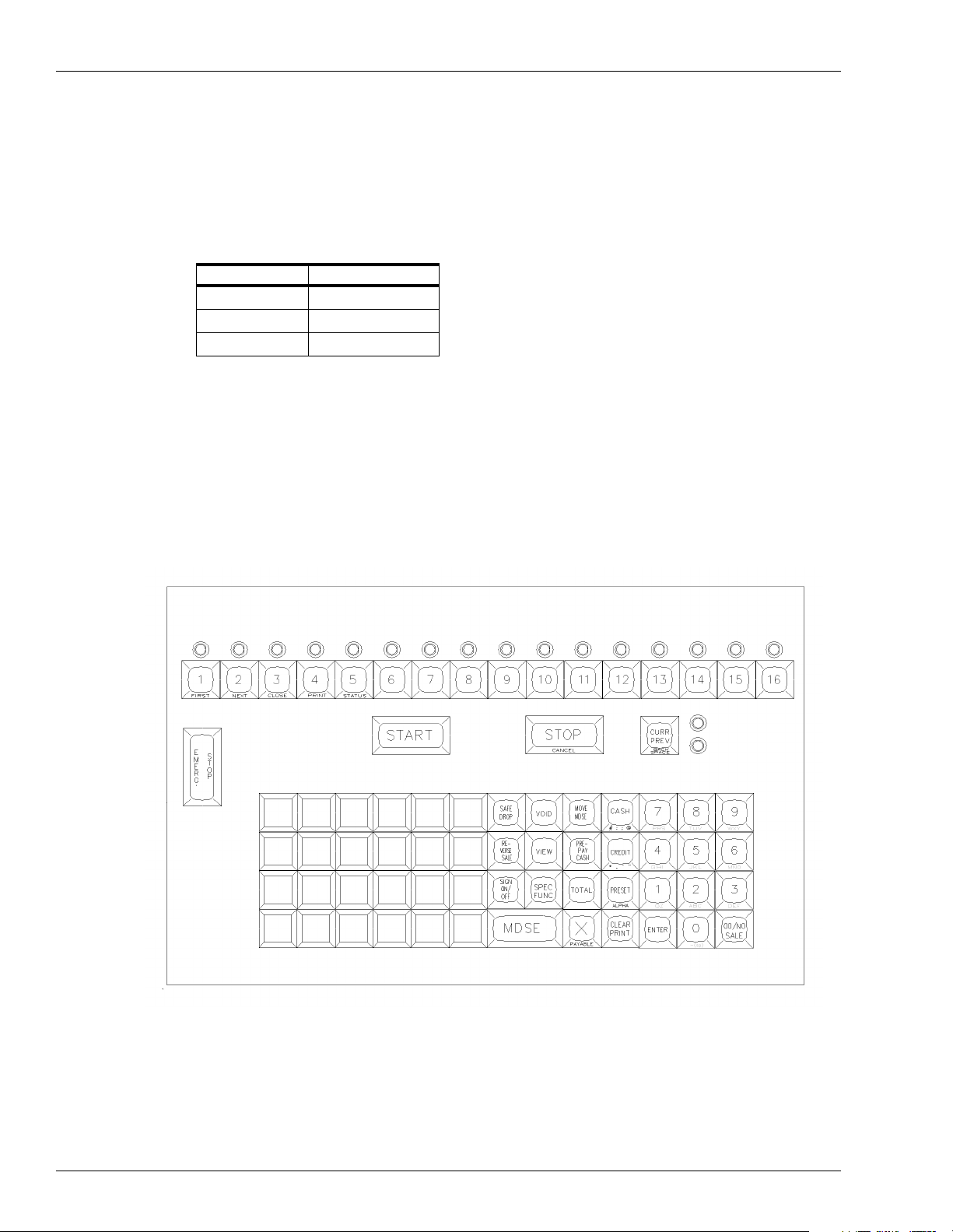
17. Check Point Default Keyboard
This drawing shows the default keyboard for the Check Point. The keyboard can be reconfigured to meet individual needs. See the Check Point Reference Manual and the Site
Controller III Configuration Manual.
Figure 2-1: Check Point Default Keyboard
Page 14 MDE-4375 CFN Series Site Controller III Start-Up Manual · June 200 5
Page 27
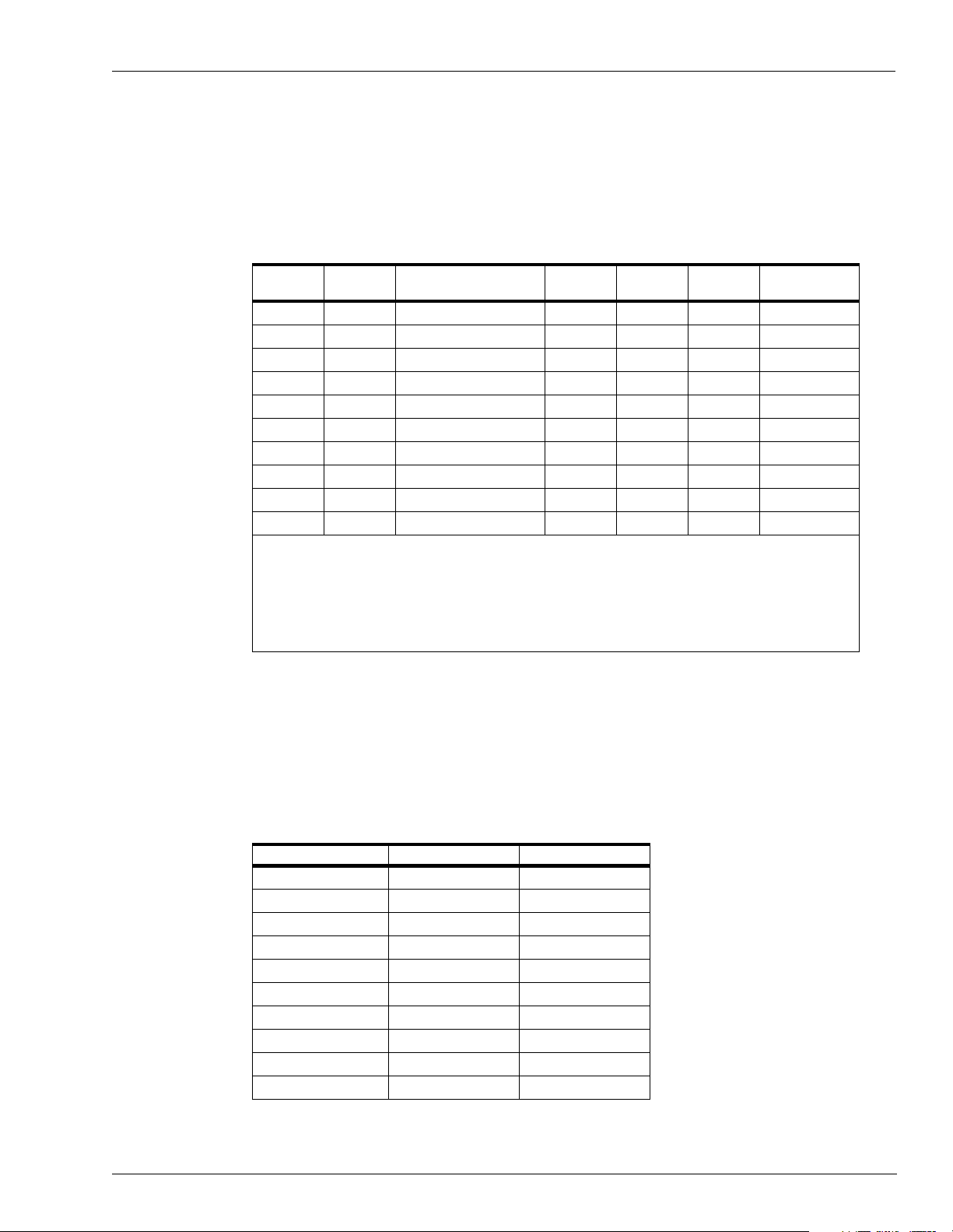
18. Load Merchandise Prods/Depts
(Referenc e: Site Manager’s Manual, LO PRO command)
Use the following table to list the site's merchandise products or departments. Use one
product/department code for each different product/department. These codes can be linked to
authorization codes when using private-issue cards.
Site Information
Prd Dpt Cat Name (12)
Prd/Dpt
Cat
Name
$Min
$Max
Tx
Prod Attr
= 2-digit product/department code
= 2-digit category
= 12 character department name
= minimum price for that department (corresponds to floor price on Profit Point)
= maximum price for that department (corresponds to ceiling price on Profit Point)
= tax code for items within that department
= product attribute value (see Site Manager’s Manual for values)
19. Load Merchandise Inventory
(Referenc e: Site Manager’s Manual, LO IN command)
$Min
(Floor)
$Max
(Ceiling) Tx Pro d Attr
Use the following table to load the initial inventory amounts and the reorder levels for your
merchandise products . Once you h ave loade d the initi al i nventor y amount s, you will use ADd
INventory to add to the inventory amount for the product.
Product Number Quantity Reorder Level
MDE-4375 CFN Series Site Controller III Start-Up Manual · June 2005 Page 15
Page 28

Site Information
20. Load Price Lookup
(Reference: Site Manager’s Manual, LO PLU command)
Use the following table to assign pr i ces f or merchandise products that do not have a minimum
or maximum price or as a default price for products that do.
Product # Price Product # Price
21. Profit Point Product Layout
(Reference: Site Manager’s Manual, LO PRO command; Profit Point Reference Manual,
Prompts for PLU Fields)
Before configuring the Profit Point, your site controller should already be set up with the
following: products/departments, prices (fuels only), tanks, pumps, and taxes. You can
transfer this information directly to the Pr ofit Point by using the POS.CMD command. This
will make it easier to enter your MASTER.PLU information on the Profit Point.
The MASTER.PLU file contains three types of data: department numbers, UPC codes, and
stock numbers. Th e charts on the followi ng three pages wi ll help you or ganize the in format ion
for each product.
Notes on Form Entries
The following descr iptio ns ar e abbr eviat ed ver sions of t he entr ies u sed i n the thre e wo rkshee ts
that follow. See MDE-4356 Profit Point Reference Manual for detailed information on these
input requirements.
Dpt = department number corresponding to the site controller’s department (Prd). See Step
19. Will always be present for departments if POS.CMD has been run.
Grp = optional group number assigned to each product.
Vnd = up to 255 vendor numbers can be defined.
Description = description (name) of department or product. See Step 19. Will already be
present for departments if POS.CMD has been run.
Ceiling = corresponds to $MAX price on site controller. See Step 19. Will already be present
for departments if POS.CMD has been run.
Page 16 MDE-4375 CFN Series Site Controller III Start-Up Manual · June 200 5
Page 29

Site Information
Floor = corresponds to $MIN price on site controller. See Step 19. W il l al rea dy be present for
departments if POS.CMD has been run.
Retail Price = selling price of this product (on departments, default price)
Per = unit upon which price is calculated.
Cost + Markup = formula to calculate pri ce: Retail = Cost + (Cost x markup %).
Rounding = no rounding or rounding up to 5 or 9.
Food Stamps = food stamps, enter Y for yes or N for no.
Disct = is discount allowed, enter Y for yes or N for no.
Cust ID = does purchase require ID, enter 1 or 2. See MDE-4356 Profit Point Reference
Manual for assigned values.
Prc Ovr = is price override allowed, enter Y for yes or N for no.
Taxes = tax code for this product (taken from codes defined in the site controller). Will already
be present for departments if POS.CMD has been run.
UPC # = 6- to 12-digit UPC code whi ch can be typed in or scann ed in using the Profit Point or
PC (PC must be set up for scanning).
Stock# = 1- to 5-digit stock number (usually entered when no UPC is available).
Whole Cost = wholesale cost of item to you.
MDE-4375 CFN Series Site Controller III Start-Up Manual · June 2005 Page 17
Page 30

Worksheet for MASTER.PLU File (Dept Entry)
Dpt #Grp #Vnd
# Description
Ceiling
($MAX)
Floor
($MIN)
Retail
Price Per
Cost +
Markup Rounding
Food
Stamps Disct
Cust IDPrc
Ovr
Note: Dpt, Description, Ceiling, and Floor information will be present on the Profit Point if the site controller POS.CMD has been run.
MDE-4375 CFN Series Site Controller III Start-Up Manual · Ju n e 20 05 Page 18
Page 31

Worksheet for MASTER.PLU File (UPC Entry)
UPC #
Dpt #Stock #Grp #Vnd
# Description
Whole
Cost Per
Retail
Price Per
Cost +
Markup Rounding
Food
Stamps Disct
Cust IDPrc
Ovr
MDE-4375 CFN Series Site Controller III Start-Up Manual · Ju n e 20 05 Page 19
Page 32

Worksheet for MASTER.PLU File (Stock Entr y)
Stock #
Dpt #Grp #Vnd
# Description
Whole
Cost Per
Retail
Price Per
Cost +
Markup Rounding
Food
Stamps Disct
Cust IDPrc
Ovr
MDE-4375 CFN Series Site Controller III Start-Up Manual · Ju n e 20 05 Page 20
Page 33

22. Profit Point Default Keyboar d
This drawing shows the default keyboard for the Profit Point. The keyboard can be reconfigured to meet i ndividual needs. See MDE-4356 Pr of it Poi nt Reference Manual for more
information.
Figure 2-2: Profit Point Default Keyboard
Site Information
DEBIT is the default.
This key can be changed to another
function, such as Food Stamps.
See MDE-4356 Profit Point Reference
Manual for details on how to redefine a key.
MDE-4375 CFN Series Site Controller III Start-Up Manual · June 2005 Page 21
Page 34

Site Information
23. Worksheet for Pump/CRIND® Device - PC Interface (if used)
Pump
Number
(Note 1)
11
22
33
44
55
66
77
88
99
10 10
11 11
12 12
13 13
14 14
15 15
16 16
17 1
18 2
19 3
20 4
21 5
22 6
23 7
24 8
25 9
26 10
27 11
28 12
29 13
30 14
31 15
32 16
Notes:
1. Pumps 17 - 32 require a second gilpump.exe session on a separate serial port. In
the parameter file for that session, set
FIRST_CHANNEL_LAST_ADDRESS = 16. Set up the gilpump.exe and crind.exe
sessions using the release diskette for each. See the appropriate installation manual
for each for more information.
2. Pump Type is determined automatically. This column is optional.
3. The Pump Number and the 2-wire Address are the same unless the
FIRST_CHANNEL_LAST_ADDRESS parameter is set. In this case, the 2-wire
Address is the Pump Number minus the FIRST_CHANNEL_LAST_ADDRESS
setting.
Pump Type (Note 2)
(H111, MPD-3, etc.)
2-wire
Address
(Notes 1 & 3)
Number
of Hoses
CRIND Address/
Reader Address
Page 22 MDE-4375 CFN Series Site Controller III Start-Up Manual · June 200 5
Page 35

Site Information
24. Worksheet for Pump/CRIND® Device - Current Loop Interface (if used)
Pump
Number
1
2
3
4
5
6
7
8
9
10
11
12
13
14
15
16
17
18
19
20
21
22
23
24
25
26
27
28
29
30
31
32
Price levels used at site: 0 1 2 3 4 5 (circle levels)
Price at level 0 is same as price at level 2: Yes No (circle one)
Price at level 0 is same as price at level 1: Yes No (circle one)
Price level for price bars: 1 2 Both None (circle one)
Pump Type
(H111, MPD-3, etc.)
2-wire
Address
PCU
Number
PCU
Slot
Number
of Hoses
CRIND
Address
Reader
Address
MDE-4375 CFN Series Site Controller III Start-Up Manual · June 2005 Page 23
Page 36

Site Information
Page 24 MDE-4375 CFN Series Site Controller III Start-Up Manual · June 200 5
Page 37

3 – Begin Start-Up Form
Parts 1 through 6
This section covers Parts 1 through 6 of the Start-up form. Parts 7 through 13 are covered in
subsequent sections. See “CFN System S tart -up Form” on page Form-1 for a blank copy o f the
Start-up forms.
1. SITE IDENTIFICATION
Customer: The name of the company that owns the system.
Contact: The name of the person who will manage the site operation.
Customer Phone: The phone number where the contact person can be reached.
Site Location: The address of the site where the system is located.
Electrician: The name of the person who did the wiring for the site.
Date/Time of Arrival: Date and time of your arrival at the site.
Date/Time of Departure: Date and time you left the site.
Distributor/Phone: The distributor involved with the sale of the system. Include phone number.
Installer/Phone: The firm that installed the system. Include phone number
Start-up Person: Your name.
Co. Name/Phone: Your company name and phone number.
Begin Start-Up Form
2. SYSTEM IDENTI F ICATION
Site #: Number of the site.
Checkmark the components that this site has.
Indicate the serial number, program version number for each of the following:
Site Controller III: Site Controller III unit. Also indicate the program name and debug version.
PCU (s): Serial number of pump control unit; program version from PCU CPU PCB.
ICR (s): Island Card Readers, program version from Reader CPU PCB.
Console:
Profit Point:
Current Loop Driver:
gilpump PC Driver: (current loop replacement)
CRIND PC Driver: (current loop replacement)
Standalone Receipt Printer:
PIN Pad:
Complete the following section only for Gasboy PC packages.
PC SOFTWARE: if applicable, indicate the version number of the PC software assigned to this site.
PC Make and Model: Indicate the make and model of the PC being used at this site.
DOS Version: Indicate the DOS version that is running on the customer’s PC.
Note: The serial number for each system device can be found on the ID tag located on the outside cover of that
device.
If pedestal pump control unit, program version from PCU CPU PCB.
Also indicate Y or N if the ICR has a receipt printer, has pedestal PCU, or is set up
as a car wash or gate controller.
MDE-4375 CFN Series Site Controller III Start-Up Manual · June 2005 Page 25
Page 38

Begin Start-Up Form
3. SYSTEM DESCRIP TION
PUMP #: Indicates the pump number.
HOSE #: Indicates hose outlet number.
FUEL TYPE: The type of fuel dispensed by that pump or dispenser (for example, No-Lead,
Regular, etc.).
FUEL CODE: The product code number (1 or 2 digits) assigned to that fuel type.
PUMP MAKE: The name of the manufacturer of the pump or dispenser.
MODEL #: The model number of the pump or dispenser.
SERIAL #: The serial number of the pump or dispenser.
RESET: The type of reset used in the pump (Veeder-Root, Tokheim #77, etc.)
TYPE SUC/SUB: The type of pump used to dispense the fuel. Submersible pump (SUB) located
in the tank or is it a suction pump (SUC) located in the pump housing? Circle
one.
PULSER RATE: The pulser rate of the pulser used by that pump or dispenser (for example,
10:1, 100:1)
STARTE R RELAY: Is an external starter relay used to supply power to the pump? Circle Y for yes
or N for no.
4. COMMUNICATIONS
Data Terminal/Logger: Circle the device or devices, if present, and indicate the make and model
Port # Baud Rate
1: Baud rate for port 1.
4: Baud rate for port 4.
5: Baud rate for port 5.
6: Baud rate for port 6.
COM1: Baud rate for COM1.
COM2: Baud rate for COM2.
Loop 1: 2/4 wire.
Loop 2: 2/4 wire.
Short Haul Modem: The make and model number of the short haul modem that is connected to the
Phone Modem: Port The make of the phone modem and the port to which it is connected. Remote
Modem Phone #: The area code and phone number for the external phone modem connected to
Network Name Port The name of the network to which the site is connecting (if appliable) and the
number of the data terminal or logger and which port to which it is connected.
system. If no short haul modems are used, indicate not applicable (N/A).
dial-in, not network.
the system. If a modem is not used, indicate not applicable (N/A).
port through which it is communicating.
Page 26 MDE-4375 CFN Series Site Controller III Start-Up Manual · June 200 5
Page 39

Begin Start-Up Form
5. BREAKER NUMBERS
Indicate the breaker number for each of the following. All breakers pertaining to the system should be in
the OFF position.
Power conditioner:
AC Surge Protector:
(Profit Point)
Islander:
(N/A for SC III)
PCUs:
(pump control units)
ICRs:
(island card readers)
Hose/Brkr #:
(hose outlets 1 to 32)
Answer the following questions:
What components are on power conditioner? Fill in all that apply.
What components are on AC Surge Protector? Fill in all that apply.
Are all Gasboy components on same breaker? Answer Y or N.
Notes:
1. The AC Surge Protector Strip must be on its own separate breaker. The Site Controller, printer, and
monitor must be plugged into the same AC Surge Protector Strip. The Profit Point must also be plugged
into an AC Surge Protector Strip.
2. The optional power conditioner should be on the same breaker as the AC Surge Protector; however, if
this is not possible, it must be in the same phase of power as the AC Surge Protector breaker. The Site
Controller III, modem, standalone receipt printer, and console should be connected to the output of the
power conditioner, if used.
6. SYSTEM ENVIRONMENT
Describe the location and environment of each system component (for example, office, outside, air
conditioned, heated). Make sure the Site Controller III is well ventilated. Nothing should rest on the top of
the Site Controller or around its vents.
MDE-4375 CFN Series Site Controller III Start-Up Manual · June 2005 Page 27
Page 40

Begin Start-Up Form
Page 28 MDE-4375 CFN Series Site Controller III Start-Up Manual · June 200 5
Page 41

4 – Physical System Layout
When verifying physical system layout, be sure power to the system has not been applied and
all power is off. All wiring and conduit runs must also conform with the National Electrical
Code (NFPA 70), the Automotive and Marine Service Stations Code (NFPA 30A), and State
and Local Electrical Codes. See C35880 Site Controller III Installation Manual for more
guidance.
Site Controller
1 Open up the PC. Perform a visual isnpection to verify that all boards are seated properly, all
connections are tight, and there are no loose or unsecured components.
2 Verify that the Site Controller is located in an office-type environment and correctly installed
according to the Site Controller III Installation Manual.
Physical System Layout
3 Verify that all data communication cables located on the back of the SC III/PC are correctly
installed according to the Site Contr oller III Installation Manual. The Site Controlle r III has
four RS-232 ports (1, 4, 5, or 6). All direct connect RS-232 cables over 15 feet must be
installed in m etal conduit separate fr om any AC wires.
Port 3 is used for communication to Tokheim pumps only; one of the RS-232 ports can be
used for communicat ion t hrough a modem or to a co mputer. The others are additional and can
be programmed according to the application. COM1 and COM2 can be programmed
according to the ap pli ca ti on; LPT1 is a parallel port whic h i s c ommonl y connected to a printer.
RS-485 communication cables (C05670, 8-foot modular cable similar to a telephone cord)
must be installed as follows:
LOOP 1 or 2 modular cable must be directly connected to either modular jack of the black
RS-485 junction box. Do not connec t Loop 1 or 2 to t he same RS-48 5 junction b ox. Loop 2 is
factory-set for 2-wire fo r communication to Tokheim DPTs.
CAUTION
If a 2-wire device, such as DPT, is connected to a loop that is set for 4-wire
communication, the site controller will not operate correctly. 4-wire devices on a 2-wire
loop may not communicate with the site controller.
Note: If using Tokheim DPTs, consult C09146 Pump Interface Manual.
LOOP 3 modular cable must be directly connected to the modular jack on the rear of the
Check Point console lab eled Si te Contr oller or to th e conver ter if connect ing to a Prof it Poi nt.
See the Site Controller III Installation Manual and the Profit Point Installation Manual for
remote console wiring considerations. If the SC III will be used as a SC III/POS WS, Loop 3
is used to connect to other POS terminals (Profit Point, CheckPoint) at the site.
MDE-4375 CFN Series Site Controller III Start-Up Manual · June 2005 Page 29
Page 42

Physical System Layout
Island Card Reader Assembly
1 Verify that the island card reader is installed to allow adequate clearance for system
maintenance. For systems with receipt printers or pedestal pump controls, a minimum of 18
inches is required between the post and any of the pumps or dispensers. This clearance meets
the NFPA 30A and NFPA 70 requirements.
2 Remove the two tamper-proof screws from either side of the black bezel, located on the front
of the island card reader head assembly. Unlock and lower the black bezel door.
3 Remove the six screws from the lower back side pedestal cover and remove the cover.
Note: No AC power should be present at TB6 in the island card reader head assembly.
4 Verify that the con dui t and a ll sy stem, pu mp, and dispe nser wi ring i s ins ta lled acc ord ing to th e
specifications detailed in the Site Controller III Installation Manual. Non-compliance with
these specifications and the checks in the accompanying Start-Up Form could void the
warranty.
Pump Control Unit(s)
1 Verify that the pump control unit(s) are installed in an area protected from direct contact with
the weather a ccording to t he Site Controller III Installation Manual.
2 Verify that the con dui t and a ll sy stem, pu mp, and dispe nser wi ring i s ins ta lled acc ord ing to th e
specifications detailed in the Site Controller III Installation Manual. Non-compliance with
these specifications and the checks in the accompanying Start-Up Form could void the
warranty.
7. CONDUIT
All Metal Conduit: Indicate if all conduit is metal and not PVC. Circle Y for yes (all metal) or N for
AC and DC is Separate
Conduit:
Wiring Neatness: Indicate the overall neatness of the installer’s wiring. Is the appearance of the
Is shielded cable used? Indicate if Gasboy C09655 or equivalent cable was used for communications
no (not all metal conduit).
Indicate if all wiring is separated in the appropriate conduits according to the
conduit specifications and exceptions detailed in the SC III Installation Manual.
Circle Y for yes if all AC and DC wiring is in separate conduits. Circle N for no if
AC and DC wiring is combined in conduits where it should not be.
wiring neat and orderly or is it very disorderly? Circle Good, Fair, or Bad.
wiring. Circle Y for yes or N for no.
Page 30 MDE-4375 CFN Series Site Controller III Start-Up Manual · June 200 5
Page 43

Checkpoint Console (Optional)
1 Verify that the CheckPoint and any optional equipment is located in an office type
environment and is correctly installed according to the Site Controller III Installation Manual.
2 Verify that th e AC power cor d fo r the Chec kPoint and the s tandal one rec eip t pri nter i s dire ctly
connected to the output of the AC Surge Protector Outlet Strip (C01218).
3 The RS-485 communication modular cable must be installed as described below. If you are
locating the CheckPoint more than eight feet from the Site Controller, you must use two
additional RS-485 junction boxes to connect the devices. See the Site Controller III
Installation Manual for remote console wiring.
SITE CONTROLLER port modular cable must be directly connected to the modular jack
port on the back of the Site Controller labeled LOOP 3.
4 Optional equipment connection:
RECEIPT PRINTER connection depends upon the type of receipt printer ordered. The
modular cable for an RS-485 printer is connected directly into the RS-485 jack on the rear of
the CheckPo int; no internal cabling is required . For a paralle l printer, the printe r cable is
connected to the D-type 25-pin female connector on the back of the CheckPoint. The cable
from the D-type connector inside the CheckPoint must be attached to P12 of the CheckPoint
PCB.
Physical System Layout
CAUTION
Be sure that the printer cabling is correct before applying power to th e system.
An incorrectly connected pr inter can cause damage to the print er , the CheckPoint,
or both.
CASH DRAWER is connected via cable from the cash drawer whi ch is termi nated by a ro und
4-pin connector and connects to the round 4-pin connector which is keyed.
CUSTOMER DISPLA Y must be installe d according to t he instructi on sheet provided wi th it.
The round 5-pin connector must be threaded as shown in the instructions and must be
connected to the 5-position connector on the back of the CheckPoint.
PIN PAD must be installed according to the Site Controller III Installation Manual. Verify
that the PIN pad is securely connected to the 9-pin connector located on the back of the
CheckPoint.
MDE-4375 CFN Series Site Controller III Start-Up Manual · June 2005 Page 31
Page 44

Physical System Layout
Profit Point Console or SC III/POS WS (Optional)
1 Verify that the Profit Point and any optional equipment is located in an office type
environment and is correctly installed according to the Site Controller III Installation Manual.
2 Verify that the AC power co rd for the Prof it Point is di rectly con nected to the output of th e AC
Surge Protector Strip (C01218).
3 The RS-485 converter must be installed as described below. If you are locating the Profit
Point more than eight feet from the Site Controller, you must use two additional RS-485
junction boxes to connect the devices.
A modular cable must be directly connected to the modular jack port on the back of the Site
Controller labeled LOOP 3. The other end of the modular cable is connected to one of the
modular jacks on the con v er te r. The converter is connected to t he Profit Point port SERIAL1
via a 25-pin to 9-pin cable. The converter power supply must be plugged into the same AC
Surge Protector Strip (C01218) as the Profit Point.
POS Distribution Box (POS D-Box) is connected via a 9-pin cable from the Serial2 port on
the Profit P oint (COM2 on the SCIII/POS WS) to the Serial2 port on the D-Box. If the site
has a PIN Pad, the Serial3 port of the Profit Point (COM3 on the SCIII/POS WS) will be
connected to the Serial3 port of the D-Box. The D-Box power supply must be plugged into
the same AC Surge Protector Strip (C01218) as the Profit Point.
“Old” CASH DRAWER is connected via a 9-pin D-type connector from the cash drawer to
the CASH DRAWER port on the back of the POS D-Box. “New” CASH DRAWER is
connected connects to the receipt printer which connects to the minitower’s 4-port fan-out
cable.
CUSTOMER DISPLAY must be installed according to the Profit Point Installation Manual.
Verify that the Customer Display is connected to the 9-pin CUSTO M ER DISPLAY port on
the POS D-Box.
4 Optional equipment connection:
RECEIPT PRINTER connection depends upon the type of receipt printer ordered. For a
parallel printer, the printer cable is connected to the D-type 25-pin female connector
PRINTER on the back of the Pr ofit Point (LPT1 on SC III/POS WS). For an RS-485 printer,
the modular cable is connected directly into the RS-485 jack on the converter. The receipt
printer must be plugged into the same AC Surge Protector Strip as the Profit Point.
PIN PAD must be installed according to the Profit Point Installation Manual. Verify that the
PIN pad is securely connected to the PIN PAD port located on the POS D-Box.
SCANNER must be installed according to the Profit Point Installation Manual. Verify that
the scanner is securely connected to the 9-pin SCANNER port located on the POS D-Box. If
a scanner is used that needs external power, it must be plugged into the same AC Surge
Protector Str ip as the Profit Point.
Page 32 MDE-4375 CFN Series Site Controller III Start-Up Manual · June 200 5
Page 45

Tank Moni tori ng System (Op tional)
1 Verify that the tank monit oring system is correctly connecte d to the Site Controller according
to the Site Controller III Installation Manual.
2 Refer to the tank monito ring system manufacturer’s installation instru ctions for specific
connection information.
Current Loop Interface (Optional)
Note: Gilbarco pump and CRIND PC interfaces are recommended over the current loop
interface.
1 Verify that the current loop interface unit is located in an office-type environment and is
correctly installed according to its installation sheet.
2 Make sure the special RS-485 communication modular cable is directly connected between
the current loop interface unit (slot labeled RS422) and the RS-485 junction box using the
appropriate RS-485 modular jacks.
Note: The modular cable from the current loop interface unit to the RS-485 junction box is
GASBOY P/N C04500 (cross) modular cable. Other devices (Site Controller, Console
to junction box, etc.) can use GASBOY P/N C05670 (1:1 cable).
Physical System Layout
3 Verify that the two wir e current l oop communicati ons is correctl y wired to the dis tributi on box
according to the Current Loop Interface Unit Ins tallation Manual or Pu mp Interface Manual.
CRIND Connections (with Current Loop Interface only)
For CRIND devices, a universal distribution box must be used. Verify that the modular cable
connects from the second RS-485/RS-422 port on the back of the current loop interface to an
adaptor , and f rom there to a 9-pi n connect or on the distri bution b ox. Refer to the Current Loop
Interface Unit Installation Manual or Pump Interface Manual.
Gilbarco Pump Interface Using PC COM Port
Install according the the Gilbarco Pump PC Interface Manual.
CRIND Interface Using PC COM Port
Install according the the Gilbarco CRIND PC Interface Manual.
Fuel Point Components
1 Verify that all the Fuel Point components are installed according to the applicable Fuel Point
installatio n manuals (listed in sec tion 1).
2 Make sure the N-ring wiring between the Fuel Point Reader and pre-amplifier is in conduit
separate fr om non-intrinsic safe wiring.
MDE-4375 CFN Series Site Controller III Start-Up Manual · June 2005 Page 33
Page 46

Physical System Layout
Electronic Pumps
All electronic pumps must be installed according to the manufacturer’s specifications. Make
sure all interface connections are made according to the SC III Installation Manual or the
Pump Interface Manual.
Page 34 MDE-4375 CFN Series Site Controller III Start-Up Manual · June 200 5
Page 47

5 – Jumpers & Switch Settings
This section covers the jumper and switch settings for the various components of your Site
Controller III system.
IMPORTANT
It is important that the jumpers and switch settings be set properly to ensure correct
operation.
Site Controller COMM CPU Printed Circuit Board
Figure 5-1: SC III Comm CPU Board
Jumpers & Switch Settings
Jumpers, K3 to K12
Jumper Function Setting
K3 AC power fail sense 2 - 3 to enable
1 - 2 to disable
K4 AC watchdog timer 1 - 2 to enable
K5 SC - Comm CPU (testing only) 1 - 2 to reset
K6 RS-485 loop 1, 2 to 4 wire 2 - 3 for 4 wire
1 - 2 for 2 wire
K7 RS-485 loop 2, 2 to 4 wire 2 - 3 for 4 wire
1 - 2 for 2 wire
MDE-4375 CFN Series Site Controller III Start-Up Manual · June 2005 Page 35
Page 48

Jumpers & Switch Setti ngs
Jumper Function Setting
K8 Rx clock from synchronous modem
K9 ETC output to synchronous modem
K10 Tx clock input from synchronous
K11 EPROM type 2 - 3 for 27256/25128
K12 EPROM type 2 - 3 for 27256/25128
Switches, S1 and S2
Switch S1 - PC IRQ
Indicates the interrupt. Only one can be selected. SC3.EXE assumes interrupt 10. No other
device can use this interrupt.
Switch Function Default
S1-1 IRQ-15 Open
S1-2 IRQ-12 Open
S1-3 IRQ-11 Open
S1-4 IRQ-10 Closed
1 - 2 to connect
(DB25-15)
1 - 2 to connect
(DB25-24)
1 - 2 to connect
modem (DB25-17)
Switch S2 - PC Address
Sets PC Dual RAM address. SC3.EXE currently assumes D0000.
Switch SW3 - Default Sign-On
Position 4 defaults to Open; Closed Normal setting.
Switch SW4 - Weights and Measures Switch
Set to Open fo r enable; Closed for disable.
Switch
Address
C0000 CCCCD6000 OCCC
C3000 CCCOD9000 OCCO
C6000 C C O C DC000 O C O C
C7000 C C O O DF000 O C O O
CC000 C O C C E0000 O O C C
CF000 C O C O E3000 O O C O
D0000 C O O C E6000 OOOC
D3000 C O O O E9000 OOOO
1234 1234
Address
Switch
Page 36 MDE-4375 CFN Series Site Controller III Start-Up Manual · June 200 5
Page 49

Site Controller Memory I/O Board
Figure 5-2: SC III Memory I/O Board
Jumpers & Switch Settings
Jumpers
Jumper Function Setting
K1 Date/Time Clock Speed 1 - 2 for 4 wait state; default
2 - 3 for 1 wait state
K2 Enable A19 to RAM 2 - 3 for 128Kx8; default
1 - 2 for 512Kx8
K3 RAM Size 2 - 3 for 128Kx8; default
1 - 2 for 512Kx8
K5 Tokheim Reset Output Not used
Switches, S1 and S2
Switch S1
Switch Function Setting
S1-1 Boot to monitor after reset Open
Boot to OS after reset; default Closed
S1-2 Debug mode Open
Normal; default Closed
S1-3 Do not talk to PC while in monitor Open
Monitor I/O goes to PC also; default Closed
S1-4 Monito r I/O goes to SC port 1 also Open
No monitor I/O to SC port 1; default Closed
MDE-4375 CFN Series Site Controller III Start-Up Manual · June 2005 Page 37
Page 50

Jumpers & Switch Setti ngs
Switch S2
Switch Function Setting
S2-1 Battery 1 Open = Disabled
S2-2 Battery 2 Open = Disabled; default
S2-3 N /A Unused
S2-4 N /A Unused
Pump Control Unit
Figure 5-3 shows the pump control unit layout. Refer to this layout when performing steps 1
through 5 under “Pump Control EXPMUX CPU Board” on page 39.
Figure 5-3: Pump Control Unit Component Location
Closed = Enabled; default
Closed = Enabled
Page 38 MDE-4375 CFN Series Site Controller III Start-Up Manual · June 200 5
Page 51

Jumpers & Switch Settings
Pump Control EXPMUX CPU Board
1 Unlock and open the front door of the pump control unit.
2 Make sure all override switches are in the AUTO positi on. See Figure 5-3.
3 Make sure the AC power and battery switches, located in the upper righthand corner of the
power supply are turned OFF (down).
4 Loosen the screw for the card cage section, and swing out the card cage.
5 Remove the pump control EXPMUX CPU board (Figure 5-4), located in the rear portion of
the card cage, by pulling on the top white tab.
Figure 5-4: EXPMUX CPU Board
6
Locate the K1 jumper patch and install the jumper. This jumper allows battery voltage to the
RAM. It should be installed for normal operation and removed for storage to prevent battery
discharge.
7 Add res s: Verify that the pu mp cont rol CPU board switch bank, SB (1 through 4), is se t fo r t he
proper address. An addres s must be se t to identify the pump control unit when it is connected
to the CFN System. This address is a unique identi fier for multiple PCU’s that are connected
on the same RS-485 line. Addressing should start at 1 and continue sequentially through 16.
The physical wiring order does not have to correspond with the address order, that is, the first
unit on the RS-485 line does not have to be address 1.
Switches 1 through 4 denote t he address. This is fa ctory set and may no t have to be correct ed.
MDE-4375 CFN Series Site Controller III Start-Up Manual · June 2005 Page 39
Page 52

Jumpers & Switch Setti ngs
The chart on the right gives the switch settings for the address selections.
Address
1 Closed Closed Closed Closed
2 Open Closed Closed Closed
3 Closed Open Closed Closed
4 Open Open Closed Closed
5 Closed Closed Open Closed
6 Open Closed Open Closed
7 Closed Open Open Closed
8 Open Open Open Closed
9 Closed Closed Closed Open
10 Open Closed Closed Open
11 Closed Open Closed Open
12 Open Open Closed Open
13 Closed Closed Open Open
14 Open Closed Open Open
15 Closed Open Open Open
16 Open Open Open Open
SB-1 SB-2 SB-3 SB-4
ADDR1 ADDR2 ADDR3 ADDR4
8 Pulser Type: Verify that switch SB-5 is set for the proper pulser type, single or dual. Settings
are shown below.
The pulser select switch is set for either single or dual puls ers . If dua l pul se rs are se lected, all
pumps on the pump control unit must have dual pulsers.
Note: The dual pulser type feature requires a PPC Motherboard III and a PPC I/O PCB III.
Both are not yet available; therefore, this switch should be closed.
SB-5
Pulser Type
Single Closed
Dual Open
DUAL
9 Del ay Time: The delay time is the period bet w een act iva ti on of the submer si ble pump and t he
activation of the slow flow and fast flow valves. The delay time switches are set to
accommodate a variety of leak detectors used in submersible pump applications. The time
should be set acc ording to th e type of le ak d etect or in stall ed on t he sub mersibl e pump t o a llow
a normal leak test for each transaction. If different leak detectors are used on each pump, set
the switches to the longes t del ay ti me required. Set the delay time to zero seconds for suct ion
pumps.
Note: The leak detect delay time feature requires a PPC Motherboard III. The PPC
Motherboard III is not yet available; therefore, these switches should be closed.
Page 40 MDE-4375 CFN Series Site Controller III Start-Up Manual · June 200 5
Page 53

Jumpers & Switch Settings
Delay Time
(seconds)
0 Closed Closed Closed
1 Open Closed Closed
2 Closed Open Closed
3 Open Open Closed
4 Closed Closed Open
5 Open Closed Open
6 Closed Open Open
7 Open Open Open
SB-6 SB-7 SB-8
RLY1 RLY2 RLY3
10 The settings for switch bank SC (1 through 4) determine when the pump control unit begins
counting pulses for a pa rticul ar pump. When a switc h is open , the PCU be gins coun ting pulses
when the corresponding pump is activated. When a switch is closed, as it should be for most
configurations using mechanical pumps, the PCU does not co unt pulses for the corresponding
pump until the mechanical reset has completed. The switch should be closed when the pump
is wired for postpay-prepay console operations.
Switch Function
SC-1 Mode pump 1 Open = Normal, Closed = Reset Complete
SC-2 Mode pump 2 Open = Normal, Closed = Reset Complete
SC-3 Mode pump 3 Open = Normal, Closed = Reset Complete
SC-4 Mode pump 4 Open = Normal, Closed = Reset Complete
11 In switch bank SC, 5 through 8, only switch 6 and 8 are active. Switch SC-6 is the Deadman
Timer Switch. If enabled, the pump control unit must be polled at least every 15 seconds by
the Site Controller. If it fails to sense a poll at that time, it turns all relays off. If Rese t
Complete Mode is used on any pump on a particular PCU, the deadman timer should be
disabled. Switch SC-8 enables the test mode allowing the basic PCU functions to be tested
without the use of a site controller.
Switch Function
SC-5 No function in on-line mode
SC-6 DEAD Open - deadman timer enabled
SC-7 No function in on-line mode
SC-8 TEST Open - Test mode; Closed - On-line mode
12 Re-install the EXPMUX Pump Control CPU board.
MDE-4375 CFN Series Site Controller III Start-Up Manual · June 2005 Page 41
Page 54

Jumpers & Switch Setti ngs
Pump Control I/O Printed Circuit Board
The Pump Control I/O PCB, shown in Figure 5-5, consists of two parts: the PCB itself and a
cover plate. In or der to set the jumpers and s w it che s o n the I/O PCB, you must remove all the
connectors and the cover plate.
1 Remov e t he five green connectors fr om t he front of the Pump Control I/ O boa rd. Remove the
board from the card cage in the same manner as the EXPMUX Pump Control CPU board.
2 Remove the four Phillips screws se curing the cover plate to the PCB and remove the c over
plate.
Figure 5-5: Pump Control I/O Cover Plate and PCB
Page 42 MDE-4375 CFN Series Site Controller III Start-Up Manual · June 200 5
Page 55

Jumpers & Switch Settings
3 Pu lse Conn ecti on: Verify that the K1 through K4 jumpers (pulse ty pe ju mpers) matc h the type
pulser being used for each pump position. Use the table below to determine your settings.
CAUTION
K1 to K4 jumpers must be set in the configurations shown before turning on power to the
PCU or damage to the system components may occur.
Jumper Pin Function Voltage
VR Reed Switch Pulser, 1871 Series
1
P Pulser signal input (sink) 12 VDC signal when pulsing
+ No connection
2
K1
VR Electronic Pulser, 7871 Series
K1
VR Totalizer Pulser, 7874 Series
K1
G DC ground for pulser DC ground
1
P Pulser signal input (sink) 12 VDC signal when pulsing
+ +12 VDC supply voltage for pulser +12 VDC
2
G DC ground for pulser DC ground
1
P Pulser signal input (sink) Signal when pulsing
+ Voltage for opto-isolator from pulser Voltage level of pulser
2
G DC ground for pulser DC ground
4 Debounce Configuration: Verify that the K5 jumper (debounce) is set properly. The K5
jumper should remain jumpered for all Reed switch quantity pulsers and unjumpered for all
electronic and money pulsers.
Jumper Speed Function
K5 Jumpered Slow 10:1 quantity pulsers
K5 Open Fast 10:1 money pulsers
All electronic pulsers
5 Replace the cover plate on the pump control I/O board and re-install the board into the card
cage.
6 Rep lace the fi ve green connect ors i nto t he prop er soc kets o n t he fro nt of the Pump Co ntrol I/O
board.
7 Repeat all steps for both the EXPMUX Pump Control CPU and Pump Control I/O PCBs for
each pump control unit.
MDE-4375 CFN Series Site Controller III Start-Up Manual · June 2005 Page 43
Page 56

Jumpers & Switch Setti ngs
Island Card Reader
DIP Switches
The island card reader has an S2 bank of 10 dip switches. Switches 1 through 6 provide
functional settings; switches 7 through 10 are address settings. The settings and functions are
shown in the following tables.
ICR Software
Switch Function
S2-1 No function
S2-2 DPT Open = enables decimal point on the keypad.
S2-3 DIS Open = two lines of display are displayed.
S2-4 INSRT Open = insertion magnetic card reader.
S2-5 GAT E Open = island card re ader.
S2-6 OPT Open = optical reader.
Closed = the decimal point acts as a CLEAR key.
Closed = only one line of display is displayed.
Closed = swipe magnetic card reader or optical reader.
Closed = gate controller.
Closed = magnetic card reader.
An address must be se t up t o ide ntif y the isla nd c ard r eader. This address is a uniqu e iden tifi er
for when multiple I CRs are connec ted on the same RS- 485 li ne. Up to 16 uni ts c an be used on
the same line (there are 16 addresses). Addressing should start at 1 and continue sequentially
through 16. The ph ysical wiri ng ord er doe s n ot hav e to c orres pond with the ad dress order (the
first unit on the RS-485 line does not have to be address 1). The chart below gives the switch
setting for the address selections.
Note: The standalone receipt printer (when used) is addressed as an island card reader; be
sure to use an address different from any ICR.
S2-7 S2-8 S2- 9 S2-10
Address
1 Closed Closed Closed Closed 9 Open Closed Closed Closed
2 Closed Closed Closed Open 10 Open Closed Closed O pen
3 Closed Closed Open Closed 11 Open Closed Open Closed
4 Closed Closed Open Open 12 Open Closed Open Open
5 Closed Open Closed Closed 13 Open Open Closed Closed
6 Closed Open Closed Open 14 Open Open Closed Open
7 Closed Open Open Closed 15 Open Open Open Closed
8 Closed Open Open Open 16 Open Open Open Open
ADDR4 ADDR3 ADDR2 ADDR1 ADDR4 ADDR3 ADDR2 ADDR1
Address
S2-7 S2-8 S2-9 S2-10
An S3 switch enables the diagnostic mode of the ICR. Diagnostic mode is enabled when the
switch is in the down position.
Switch Function
S3 Up = normal; Down = test mode
Page 44 MDE-4375 CFN Series Site Controller III Start-Up Manual · June 200 5
Page 57

Jumpers & Switch Settings
Diagnostic tests can be started by keeping the face of the ICR open and pressing the START
OVER key on the keypad.
Note: If you have the island receipt printer, see C08951 Star Receipt Printer Maintenance
Manual for switch settings and other information.
CPU PCB Jumper Settings
Jumpers on the CPU PCB are used for very basic configurations on the PCB and usually do
not need to be set in the field.
Note: When used with an optical reader, these jumpers can be removed or left at the factory
settings.
Reader Type
Magnetic Card Reader K4, 1 & 2 K4, 2 & 3 K5, 1 & 2 K5, 2 & 3
American Magnetics Jumpered Open Jumpered Open
Omron/Magtek Open Jumpered Open Jumpered
Disable Pumps PC Board Jum p er Settings
The Disable Pumps PC Boar d is locat ed wit hin the head of the Isla nd Card Reader. It is on the
left side directly below the board labeled RS-485 Protection Board. If the site’s island card
reader is equipped with an Disable Pumps button, check the K1 jumper on the Disable Pumps
PC Board. The Disable Pumps button attempts to shut off pumps regardless of the jumper
setting, but the setting determines the following:
• If the jumper is on and the site is configured for emer ge ncy stop, when the Disabl e Pumps
button is pressed, the pumps are shu t down and the si te logs an Emer gency S top conditi on.
It also shuts off pumps not connected to the RS-485 loop (that is, Tokheim pumps).
• If the jumper is off and Disable Pumps is pressed, the pumps just shut of f an d no message
is logged at the Site Controller.
MDE-4375 CFN Series Site Controller III Start-Up Manual · June 2005 Page 45
Page 58

Jumpers & Switch Setti ngs
RS-232/RS-485 Converter
The following chart shows the default jumper settings for the RS-232/422 converter board.
Note: If using a tank monitor or Profit Point, be sure all jumpers are set to their default
settings.
Jumper Pin Function
K1 K2
1
2
3
K3 K4
1
2
3
K5
1 & 2 Jumpered, slave side of 485 loop transmits; default
2 & 3 Jumpered, master side of 485 loop transmits
1 & 2 Jumpered, tank monitor or PC; default
2 & 3 Jumpered, other application if positions 1 & 2 do not work
Always jumpered
K6
1
2
K7
1
2
POS Distribution Box (D-Box)
The following chart shows the default jumper settings for the POS D-Box.
Jumper Function
K1
1
2
K2
1
2
K3
1
2
Jumpered, supplies +12 volts to pin 4 at the scanner port
Unjumpered, disconnects pin 4 of the scanner port
Jumpered, supplies +5 volts to pin 9 of the scanner port
Unjumpered, disconnects pin 9 of the scanner port
Jumpered, supplies +12 volts to pin 4 of the customer display port
Unjumpered, disconnects pin 4 of the customer display port
Jumpered, listens to slave responses or for PC monitor
Unjumpered, tank gauge; default
Jumpered, 232 device listens to master side of 485 loop; default
K4
1
2
Jumpered, supplies +5 volts to pin 9 of the customer display port
Unjumpered, disconnects pin 9 of the customer display port
Page 46 MDE-4375 CFN Series Site Controller III Start-Up Manual · June 200 5
Page 59

Fuel Point Reader
The switches on the Fuel Po int Rea der (FPR) CPU PCB (see Fi gure 5- 6) must be set a s shown
(see “Switch SW1” on page 48) to work with the CFN system.
Figure 5-6: Fuel Point Reader CPU Printed Circuit Board
Jumpers & Switch Settings
MDE-4375 CFN Series Site Controller III Start-Up Manual · June 2005 Page 47
Page 60

Jumpers & Switch Setti ngs
Switch SW1
Switch Setting
1ON
2ON
FPR Address Switch 3 Switch 4
1OFFOFF
2OFFON
3ON OFF
4ON ON
Pumps and Dispensers
If you are using GASBOY Series 9800 pumps and dispensers, there are switches that must be
set correctly to insure proper operation of your CFN system. See the Series 9800 Installation/
Operation Manual for details.
If you are using a Gilbarco
Wayne
®
, etc.) refer to C09146 Pumps Interface Manual.
Standalone Star Printer
The switches on the standalone Star printer are set at the factory and should be correct. If
change is needed, refer to the CFN D iagnostic M anual for details.
®
CRIND device or another pump interface (Tokheim DPTs,
Page 48 MDE-4375 CFN Series Site Controller III Start-Up Manual · June 200 5
Page 61

6 – System Power
1 Verify that th e AC power for the CFN Series Syst em is in acco rdance wi th the Site Controller
III Installation Manua l. AC Power for the CFN system compone nts , monitor, printer, external
modem, and remote terminal must come from a separate, dedicated circuit breaker. No other
equipment, including the system’s pumps or dispe nsers, should be powered fro m thi s bre aker.
Gasboy recommends all CFN components be on the same brea ker; however, it is acceptable to
supply the power to the different CFN system components and accessories from multiple
breakers within the sam e breaker panel. When necessary, power for the data terminal or
modem may be supplied from a separate, dedicated breaker located in a different breaker
panel.
Power for the system should be 120 VAC + 10% 47-63 HZ. Power for the CFN system
components must come from the AC Surge Protector Outlet Strip supplied with the system
(except for the pump con trol unit, island card reader, electronic pumps/dispensers, and the
Profit Point). The Profit Point and its accessories (scanner, PIN pad, etc.) must be plugged
into anoth er AC surge protector stri p.
System Power
8. SYSTEM POWER
Record the Grounding method as outlined in step 2 below. Then, record voltage readings for each
component from step 4 for Hot to Neutral, Hot to Ground, and Neutral to Ground.
IMPORTANT
Proper system grounding is an extremely important part of the system installation.
2
Grounds for all system devices should be wired to the breaker panel ground bus bar which, in
turn, should be grounded to a single ground rod. A conduit ground does not provide a
sufficient gr ound. It is r ecommended tha t the neu tral and ground bus bars be bo nded toget her
unless prohibited by local codes.
3 Be sure all power switches for the system’s devices are in the OFF position. Turn on the
circuit breakers for the system’s devices; optional power conditioner, pump control units, and
island card readers and turn on the AC surge protector switch.
4 On t he specified locations of the following components, use a di gi ta l AC voltmeter to test and
record the voltages as follows:
• Optional power conditioner - on the output receptacle (see F igu re 6-1)
• AC surge protector strip - on the output receptacle (see Figure 6-1)
• Pump control unit(s) - at TB202
• Island card reader(s) - at TB6
MDE-4375 CFN Series Site Controller III Start-Up Manual · June 2005 Page 49
Page 62

System Power
Figure 6-1: AC Output Receptacle
N
(neutral)
G
(ground)
Measure
Hot Neutral Measure AC voltage between the H and N screws.
Hot Ground Measure AC voltage between the H and G screws.
Neutral Ground Measure AC voltage between the N and G screws.
Note: If power is not within these specifications, correct it before you continue.
H
(hot)
RangeFrom To
This voltage should be 120 VAC ± 10 percent (108 VAC to 132 VAC).
This voltage should be 120 VAC ± 10 percent (108 VAC to 132 VAC).
This voltage should be 0 VAC ± 1 volt.
Page 50 MDE-4375 CFN Series Site Controller III Start-Up Manual · June 200 5
Page 63

7 – Pump/Dispenser Manual Test
Verify General Guidelines
Verify that the general guidelines listed below were met when installing the system’s pumps
and dispensers. If your system contains any electronic pumps, follow the appropriate
installation manual for applicable tests.
Suction Pumps
The CFN System is capable of directly driving pump motors up to 3/4 HP at 120/240 VAC or
1-1/2 HP at 240 VAC. A starter relay must be used with pump motors exceeding these
limitations. A separate circuit breaker should be supplied for each pump to meet the current
requirements and to allo w for isolated control w ith the circuit breaker panel in case of
problems.
Dispensers
The CFN System is capable of directly driving submersible pumps up to 3/4 HP at 120/240
VAC or 1-1/2 HP at 240 VAC. A dispenser with a submersible pump exceeding these
limitations will r equire t he use of a submersi ble sta rter re lay. A separate circuit breaker should
be supplied for each dispenser in cases where it will directly drive the submersible pump.
Dispensers may be grouped together on a single breaker when the submersible pump has its
own breaker. It is recommended that no more than two dispensers be powered from one
breaker to maintain isolated control with the circuit breaker panel in case of problems.
Pump/Dispenser Manual Test
Manual Override Test
The pumps and/or dispensers should be tested to verify AC wiring. The steps below indicate
the proper procedure for testing and the expected results. If any of these tests fail, correct the
wiring and perform the test again. See Figure 5-3 on page 38 for location of the override
switches.
WARNING
Power up only the pump control unit(s) during these tests!
1 Remove all wiring connectors (green) from the pump control I/O board located in the front of
the card cage. This will prevent any d amage to the PCBs if wirin g is incorrect. Make sure
connectors are not touching any metal surfaces.
2 Turn on the breakers for all pumps and/or dispensers.
WARNING
Do not turn on the AC power for the site controller, monitor, checkpoint, profit
point, etc.
MDE-4375 CFN Series Site Controller III Start-Up Manual · June 2005 Page 51
Page 64

Pump/Dispenser Manual Test
3 Turn the AC power and battery power switches, in the pump control unit located in the upper
righthand corner of the power supply, to the ON position (up).
AC power is present on the terminal blocks. Electrical shock may occur if the
operator comes in contact with these connections.
4 Place the system override switch for Hose 1 in the MAN (manual) position.
5 Turn on Hose 1. After completing reset, the hose should be able to dispense product.
6 Turn on all other hoses. No other hoses besides 1 should activate.
7 Turn off all hoses.
8 Place the system override switch, for Hose 1 in the ON position.
9 Repeat steps 4 through 8 for all remaining hoses. Substitute the hose number being tested for
hose 1 until all hoses have been tested.
WARNING
10 Replace all connectors and reassemble.
Page 52 MDE-4375 CFN Series Site Controller III Start-Up Manual · June 200 5
Page 65

Component Power-Up and Configuration
8 – Component Power-Up and Configuration
Tu rni ng On AC Power
Turn on the AC POWER for all system devices as follows.
Power Conditioner/AC Surge Protector Strip
Plug in device. Turn on power switch if applicable.
Monitor
Locate the AC power swit ch on the moni tor and t urn on. See t he operato r’s manual for monitor
adjustments and LED indicator s.
Logger/Printer
Locate and turn on the A C power switch for the logger/printer. If using a Link ter minal for
remote log-in, see the s etup parame ters later in this section.
CheckPoint or Profit Point
CheckPoint: Locate the AC power switch on the back side of the unit. Push the switch down
to the ON position marked 1. Verify that the console is on by observing the display on the
front of the unit. If the site has an optional customer display, verify that it is also working.
Profit Poi nt: Locate the AC power switch on th e front lo wer righ thand side of the monit or and
the AC power switch on the back righthand sid e of the Profit Point console. Push the switch
for the monitor into the ON position; then do the same for the console. Verify that it powers
up.
Site Controller
Locate the AC power switch on the fr ont of t he PC and t urn it on. S ome uni ts may al so have a
power switch in the back.
Verify that the Site Controller is operating properly. Verify that power up message prints on
monitor and/or logger.
Island Card Reader (ICR)
Locate the AC power switch inside the ICR assembly , upper righthand corner and turn it up to
the ON position. Verify that the two power suppl y LEDs (r ed) are li t. Verify that the t wo 485
communication LEDs (red) , locat ed on the up per lef thand c orner of th e reade r CPU board, are
flashing.
Pump Control Unit(s)
Locate AC power switch and battery switch and turn them on. Verify that the two power
supply LEDs (red) are lit. Verify that the two RS- 485 communicat ion LEDs (r ed) on th e pump
control CPU board are flashing.
Electronic Pumps and Dispensers
Locate and turn on power switches. Refer to the Pump Interface Manual or call Gasboy
Technical Service for informatio n.
MDE-4375 CFN Series Site Controller III Start-Up Manual · June 2005 Page 53
Page 66

Component Power-Up and Configuration
Standalone Receipt Printer (optional)
Locate the AC power switch on the front of the unit. Push the switch to the right (ON)
position.
Fuel Point Reader (if used)
Locate and turn on the power switch in the top-left side of th e FPR. Verify that the power
supply LED, visible through the perforated screen, is lit. Verify that the two RS-485 LEDs,
DL3 and DL4 on the FPR CPU PCB, are flashing.
Configuring the Checkpoint Console
With prior console models, configuration was accomplished with switches and jumpers. This
configuration procedure replaces the switch and jumper settings.
If the console has never been configured or if its configuration has been erased, it will go into
configuration mode at power up. Otherwise, you can access configuration mode by using selftest 7. Accessing self-test mode is described later in this section. The following table show s
the configuration options and their possible values. The shaded column shows the default
value.
Options Values
Console poll address
Keyswitch type
Cash drawer
Drawer switch type
Beeper
Alert beep type
Key click type
LED color
Deadman timer
Console printer/pad
Printer address
DES
Receipt line feed, top
Receipt line feed, end
Receipt left margin
Printer
Printer port
Decimal position
Decimal point type
Ignore scan nn
Note: If used, console printer address cannot be the same as the ICR receipt printer address.
1234
4 posn 2 posn
Cash drawer No cash drawer
Dr clo=sw closed Dr clo=sw open
Enabled Disabled
15 seconds 8 seconds 4 seconds 2 seconds
Short Medium Long No
Normal Reverse
On Off
No cons prnt/pad Console prnt/pad
01 01 - 64
Disabled Enabled
00 00 - 10
10 00 - 18
04 00 - 10
Star SP300 Undefined
Serial Parallel
2 (.00) 3 (.000) 0 1 (.0)
. (period) , (comma)
57 31 - 59 62 - 77 99
99 31 - 59 62 - 77 99
99 31 - 59 62 - 77 99
99 31 - 59 62 - 77 99
99 31 - 59 62 - 77 99
Page 54 MDE-4375 CFN Series Site Controller III Start-Up Manual · June 200 5
Page 67

Component Power-Up and Configuration
To configure the console:
1 Turn the key to MGR position and press the NO SALE key.
Access diagnostic mode, self-test 7, if necessary. See the Check Point Reference Manual if
further assistance is required. The message ***Configuration** appears and the display
scrolls through the keystrokes needed to change the values. Then the first option appears. If
the value selected for the option is the default value, the option is enclosed in asterisks (*). If
the value is not the default, the option is enclosed in minus signs (-).
2 Accept the defaults or change the values for any of the configuration options using the
following keys:
ENTER accepts the displayed value and displays the next configuration option.
PREV selects the currently displayed option value and displays the previous option. For example,
1 displays the next value for that option. To accept that option and go on to the next option,
2 displays the default value for the option. T o accept that option and go on to the next option,
0 exits the configuration mode and saves your changes.
7 returns you to the initial configuration display.
if you’re on keyswitch type and press this key, console address is displayed.
press ENTER.
press ENTER.
3 Exit from diagnostic self-test mode by pressing 9.
Fluorescent Display Board
Switch Function
SW1-1 Not used
SW1-2 Not used
SW1-3 Not used
SW1-4 MSTR Open = display only (the characters are only displayed)
Closed = display and transmit to customer display (the VF driver transmits characters
through its serial interface and simultaneously displays them.)
Note: Must be closed when console is connected to a customer display.
SW1-5 SLAV Open = VF driver used in console (the VF driver displays characters received through
its parallel interface)
Closed = VF driver not used in console (the VF driver displays all characters received
through its RS-485 interface)
Note: Must be open when VF driver is used in the console.
SW1-6 TEST Open = normal mode (the VF driver functions normally)
SW1-7 Not used
SW1-8 Not used
Closed = test mode (with the CPU interface ribbon cable disconnected, the VF driver
displays a rotating barber-pole pattern self-test)
MDE-4375 CFN Series Site Controller III Start-Up Manual · June 2005 Page 55
Page 68

Component Power-Up and Configuration
Configuring the Profit Point Console
Access the Main Menu from Profit Point Console
1 Turn the Manager’s key to MGR position.
2 Sign on (if required).
3 Press SPEC FUNC, 0 and ENTER. The Main Menu displays.
Note: To return to POS mode, select 1 on the Main Menu and press ENTER.
Access the Main Menu from SC III/POS WS
1 Minimize the SC III window and double-click on the PP icon
2 Sign on (if required).
3 Press SPEC FUNC, 0 and ENTER. The Main Menu displays.
Note: To return to POS mode, select 1 on the Main Menu and press ENTER.
4 On the Profit Point Main M enu, press 4 (or C) and ENTER. This displays the Configuration
Menu
5 Select configuration options by selecting the number or first letter of the option and pressing
ENTER.
Note: The options are 1: Software, 2: Hardware, 3: Keyboard, and 4: Setup config.pos file.
Software Configuration
Type 1 (or S) and press ENTER to display the Software Configuration menu.
When you select an entry, a submenu appears allowing you to select the desired options for
that entry. The entries are:
1 Training mode off-hook rate Enter a value from 1 (slowest) to 9 (fastest)
2 Show change as coins and bills Shows yes to show change, or no
3 Minimum age to buy ask-ID items Shows one or two ID ages, depending on selections
4 Product to tals kept in PLU file Shows yes to update product totals, or no
5 Keep file of missing items Shows yes to keep a file, or no
6 Off-hook beep rate Enter a value (15 seconds, standard) for length of time between 3
7 Validate checks Prints date, time, register number, clerk number, and amount
8 Enter birthdate when ID required Select 1 for require; select 2 for do not require
9 Head Clerk signon Enter user ID and password for head clerk. Used for keyswitch
beep signals indicating pump is off-hook
tendered on checks accepted
position 2 when 5-position keyswitch is used.
Page 56 MDE-4375 CFN Series Site Controller III Start-Up Manual · June 200 5
Page 69

Component Power-Up and Configuration
Hardware Configuration
Type 2 (or H) and press ENTER to display the Hardware Configuration menu. When you
select an entry, a submenu appears allowing you to select the desired options for that entry.
The entries are:
1 Console address Enter address of console
2 Address of printer/PIN pad Enter address of PIN pad
3 Type of PIN pad used Four choices: local (keyboard), Ingenico Verifone, none
4 Customer display type Two choices: Ultimate, IEE
5 Profit Poi nt type Two choices: modular, integral
6 Bar code scanner Select enabled/disabled
7 Key switch type Three choices: 2-position, 3-position, 5-position
8Drawer type Four choices: switch open = drawer open, switch open = drawer
9 H os t IP address Not used at this time
closed, drawer on printer (requires Epson serial printer), no cash
drawer
Keyboard Configuration
Keyboard may be different for every site. Consult MDE-4356 Profit Point Reference Manual
for keyboard configuration details.
Set Up CONFIG.POS File
When you set up the CONFIG.POS file, you specify the special network cards your site
accepts, the user-defined menus you want, the sale discounts you offer, the permission level
required to use each of the Profit Poi nt’s special functions, and idle me ssages for display.
Refer to MDE-4356 Profit Point Reference Manual for details.
Printer Configuration Submenu
The printer configuration submenu allows you to select a forms or invoice printer and specify
the port (LPT1 or LPT2) to which it is connected. The receipt printer, if present, is still
connected to LPT1 and prints receipts regardless of this configuration. Refer to MDE-4356
Profit Point Reference Manual for details.
Scanner Configuration
When purchased from Gasboy, the scanner should be set up at the factory. If it is not, it is
programmed by scanning bar codes supplied with the scanner. A configuration instruction
sheet, including a list of required bar codes, is packed with the scanner. Refer to MDE-4356
Profit Point Reference Manual for scanner port parameters.
MDE-4375 CFN Series Site Controller III Start-Up Manual · June 2005 Page 57
Page 70

Component Power-Up and Configuration
Okidata Printer/Logger
The following printer switch settings are applicable for the Okidata 184 printer when
connected to a GASBOY CFN Fuel Management System. Thi s document is not in tended to be
a complete reference for the printer. Consult the documentation that came with the printer.
To prepare the Okidata 184 printer for operation with your GASBOY Fuel Management
System, perform the following step s. Install and complete the setup of the printer as specified
in the manufacturer’s setup instructions. Then set up the switches as follows:
SW1-1 ON Parity: Odd
SW1-2 ON Parity: Without
SW1-3 ON Data bits: 8
SW1-4 OFF Protocol: XON/XOFF
SW1-5 ON Test select: Circuit
SW1-6 ON Mode select: Print
SW1-7 ON Busy line selection: DTR - Pin 20
SW1-8 ON Busy line selection: DTR - Pin 20
SW2
Baud Rate SW2-1 SW2-2 SW3-3
9600 OFF ON ON
2400 OFF OFF ON
1200 ON ON OFF
300 ON OFF OFF
Note: Any change to the baud rate must also be changed on the Link Terminal
Communications Setup screen, Aux Baud parameter.
SW2-4 ON DSR output signal: Active
SW2-5 ON Buffer threshold: 32 bytes
SW2-6 OFF Busy signal timing: 1 second (minimum)
SW2-7 ON DTR signal: Space after power on
SW2-8 OFF Not used
1 Take the printer offline by pressing SELECT. The SELECT light should go off.
2 Position the print head at the top of the paper and press the TOF SET button.
3 Put the printer back online by pressing SELECT. The SELECT light should go on.
4 Press the MODE button until the light next to HSD is lit.
5 Press the PITCH button until the light next to 17 is lit.
Note: Pitch may be set to a lower number ( resulting in larger print) if transactions are less
than 132 characters.
Page 58 MDE-4375 CFN Series Site Controller III Start-Up Manual · June 200 5
Page 71

Remote Terminal Setup
The CFN remote port can be directly connected to a terminal. The terminal supplied by
GASBOY is a Link MC5 CRT terminal. If your site uses a remote terminal, install and
complete the setup of the terminal as specified in the manufacturer’s setup instructions. The
baud rate amd emulation mode must be set to match the Site Controller configuration.
Site Controller Configuration Changes
Although the system has already been configured and tested at the factory, you may need to
perform some configura tion change s to matc h the site’s ch aracter istics. Fo llow the instructio ns
in the Site Controller III Configuration Manual to make these changes.
The software for a CFN syst em with a 3 -1/2" di sk dr ive a nd a hard disk is su pplied on th e h ard
disk and also on two backup 3-1/2" diskettes. During normal system use, any configuration
changes that you add to t he CFN syst em are a utomati cally plac e on th e hard disk. To keep your
backup current, these changes must be copied onto the 3-1/2" backup diskette labeled DISK
#1.
The possible configurat ion programs are: SYS_PAR, READER, PUMP, CONSOLE, TABLE,
TRFMT, PERM, GATE, and FUELPT. Detailed information on these programs can be found
in the Configuration Manual. The following list contains items which may require changing
the site controller configuration.
• Use SYS_PAR parameters to change the Site ID #, Switch timeouts, and Pulser timeouts.
• Serial port configuration. Be sure all devices are plugged into the correct ports, and the
printer (if p resent) is se t up according to the ins tructions provided earlier in this section.
• Use PUMP to check configuration to make sure correct pumps were set up at the factory.
Reassign pump control units if changes were made to previous pump types. If pulse rates
need to be changed, open S4 at the back of the Site Controller I II boar ds ( sl ide away f rom
loop connectors).
• If using a network, refer to t he applicable Credit and Debit Card Networks Ma nual, for
specific network configuration considerations.
• If using Tokheim Dispenser Payment Terminals (DPTs), refer to DPT Instructions
available in C09146 Pump Interface Manual or contact GASBOY Technical Service.
• If using a CheckPoint or Profit Point, refer to the appropriate manuals listed in Section 1
for any special configuration considerations.
• If using Gate Reader, it is possible to configure the Prompts and Timeouts parameters.
• If using a tank monitoring system, it is possible to configure the add to inventory and log
delivery parameters.
• Use FUELPT to set the nozzle ring assignments and other Fuel Point pa rameters.
• If using Unitec Car Wash option, you can use the GATE program to set parameters, types,
and discounts.
Component Power-Up and Configuration
Series 9800 Electronic Pumps and Dispensers
If you are using Series 9800 pumps and dispensers, there are switches that must be set
correctly to insure proper operation of your CFN system. See the Series 9800 Installation/
Operation Manual for details.
MDE-4375 CFN Series Site Controller III Start-Up Manual · June 2005 Page 59
Page 72

Component Power-Up and Configuration
Page 60 MDE-4375 CFN Series Site Controller III Start-Up Manual · June 200 5
Page 73

DC Power Measurement and Adjustment
9 – DC Power Measurement and Adjustment
The following steps describe, for each of the components, how to measure the voltages
required in Section 9. DC POWER of the Start-up form. If any of the measured DC voltages
are outside of the tolera nces noted (e xcept for +5 whi ch can be adjust ed), immediat ely shut of f
the AC POWER switch of the unit and diagnose the problem. Test points are shown for each
of the system devices in this section. All voltage measurements should be taken with the
negative lead of the digital voltmeter on the ground (GND) test point.
9. DC POWER
As you are measuring the noted voltages, fill in the readings for each in this section of the Start-up
Form.
Site Controller III
The Site Controller III has no DC power adjustments.
Pump Control Unit(s)
+5 VDC Measurement
1 Turn off the AC and DC power switches on the supply assembly.
2 Locate the connector labeled POWER in the upper left-hand corner of the motherboard.
Remove the black plastic cover.
3 Turn on the AC and DC power switches.
4 Measure the +5 VDC between the orange (+) and black (-) wires (Figure 9-1).
The voltage should be +4.95 to +5.05 VDC.
Figure 9-1: PCU +5 VDC Measurement Points
MDE-4375 CFN Series Site Controller III Start-Up Manual · June 2005 Page 61
Page 74

DC Power Measurement and Adjustment
5 Measure the +12 VDC between the red (+) and black (-) wires (Figure 9-1).
The voltage should be +11.50 to +15.50 VDC depending on the type and number of pulsers
and the number of relays energized.
6 Measure the POWER FAIL between the yellow (+) and b l ack (-) wires (Figure 9-1).
The voltage should be +4.75 to +5.05 VDC.
Note: There are no adjustments for these voltages.
7 Turn off the AC and DC power switches.
8 Rep lace the bl ack plast ic cover on the co nnector and turn the AC and DC power switches ba ck
on.
Island Card Reader
+5 VDC Measurement
1 Unlock, unscrew, and lower the face of the island card reader.
2 Measure the +5 VDC between the top of the resistor R7 (+) and the case of crystal Y1 (-)
(Figure 9-2).
The voltage should be +5.00 to +5.10 VDC.
• If the voltage does not fall within this range, adjustment is necessary. Follow the steps in
+5 VDC Adjustment below to adjust the supply.
• If the voltage is within tolerance, skip to “+12 VDC Measurement” on page 63.
Figure 9-2: ICR +5 VDC Measurement Point
+5 VDC Adjustment
1 Turn off the AC POWER switch in the island card reader.
2 Remove the two white connectors on the power supply labeled DC OUT and AC IN.
3 Remove the four 5/32-inch nuts on each corner of the power supply, and remove the supply.
4 Being careful that it does not touch any of the circuits on the front door, lay the power supply
on a non-conductive surface (such as heavy plastic or cardboard).
Page 62 MDE-4375 CFN Series Site Controller III Start-Up Manual · June 200 5
Page 75

DC Power Measurement and Adjustment
5 Reconnect the two connectors on the power supply labeled DC OUT and AC IN.
6 Attach the meter probes to R7 and Y1 on the CPU PCB.
7 Turn the AC POWER switch back on.
WARNING
Be careful not to touch anything but the adj ustment screw. High voltage exists at
various points on the supply and the circuit mounted on the rear of the supply.
8 Usi ng a 1/8 inch or smaller p las ti c, fl at blade screwdriver, adjust the power s upp ly t o +5 VDC
by turning the screw clockwise to increase voltage, counterclockwise to decrease voltage.
Turn the screw slightly to judge how sensitive the adjustment is.
9 Disconnect the meter probes.
10 Turn the AC POWER switch off and return the power supply to its normal location.
11 Fasten the nuts holding the supply.
12 Turn the AC POWER switch back on.
+12 VDC Measurement
1 Meas ure the +12 VDC between the red (+) and bla ck (-) wir es on the DC OUTPUT connector
of the power supply (Figure 9-3).
The voltage should be +11.00 to +14.00 VDC.
Figure 9-3: ICR +12 VDC M easurement Point
Close and lock the unit, and replace the screws on the face.
2
MDE-4375 CFN Series Site Controller III Start-Up Manual · June 2005 Page 63
Page 76

DC Power Measurement and Adjustment
Checkpoint Console
+5 VDC Measurement
1 Turn off power to the console.
2 Remove the four screws from the bottom of the console and carefully separate the upper
housing from the lower housing.
3 Turn on the power to the console.
4 On th e CPU PCB, measure at the TP1 and TP2 te st poi nt s, wit h the pos it iv e (+) probe on TP1
and the negative (-) probe on TP2 (Figure 9-4).
The voltage should be +5.00 to +5.10 VDC.
• If the voltage does not fall within this range, adjustment is necessary. Follow the steps in
+5 VDC Adjustment below to adjust the supply.
• If the voltage is within tolerance, skip to “+12 VDC Measurement” on page 65.
Figure 9-4: Checkpoint +5 VDC Measurement Point
+5 VDC Adjustment
1 Turn off the power to the console.
2 Rem ov e the three screws that hold the power supply cover onto t he supply; remove the cover.
3 Attach the meter probes to TP1 and TP2 on the CPU PCB.
4 Turn the AC POWER switch back on.
WARNING
Be careful not to touch anything but the adj ustment screw. High voltage exists at
various points on the supply.
5 Usi ng a 1/8 i nch or smal ler pla stic , flat-bl ade scr ewdrive r, adjust the power supply to +5 VDC
by turning the screw clockwise to increase voltage, counterclockwise to decrease voltage.
Turn the screw slightly to judge how sensitive the adjustment is.
Page 64 MDE-4375 CFN Series Site Controller III Start-Up Manual · June 200 5
Page 77

DC Power Measurement and Adjustment
6 Disconnect the meter probes.
7 Turn the AC POWER switch off and return the power supply cover to its normal location.
8 Turn the AC POWER switch back on.
+12 VDC Measurement
Locate TP3 (+12VDC) on the CPU PCB; measure the +12 VDC between TP3 (+) and TP2
(gnd) on CPU PCB.
The voltage should be +11.00 to +14.00 VDC.
Note: This volta ge is not adjustable.
-12 VDC Measurement
Locate TP4 on the CPU PCB; measure the -12 VDC between TP4 and TP2 on the CPU PCB.
Voltage should be -11.00 to -14.00 VDC.
Note: This volta ge is not adjustable.
+9 VDC Measurement
1 Locate TP5 on the CPU PCB; measure the +9VDC between TP5 and TP2 on the CPU PCB.
Voltage should be +6.00 to +10.00 VDC.
Note: This volta ge is not adjustable.
2 Turn off power to the console and carefully set the upper half of the console on the lower half.
3 Replace the four screws in the bottom of the unit.
4 Turn on the power.
MDE-4375 CFN Series Site Controller III Start-Up Manual · June 2005 Page 65
Page 78

DC Power Measurement and Adjustment
Fuel Point Reader (FPR)
+5 VDC Measurement
1 Unlock, unscrew, and remove the FPR door.
2 Using a DC voltmeter, measure the +5 VDC between the GND test point and the right side of
R26, both located on the FPR CPU PCB (Figure 9-5).
3 The acceptable voltage range is +5.0 to +5.1 VDC, but try to adjust it as close as possible to
+5.0 VDC.
Note: There is an access hole in the power supply bracket to facilitate adjustment without
disassembly.
Figure 9-5: Fuel Point Reader+5 VDC Measurement Point
Page 66 MDE-4375 CFN Series Site Controller III Start-Up Manual · June 200 5
Page 79

Profit Point Console
There are no DC power adjustments in the Profit Point console.
Current Loop Interface
Consult the Current Loop Interface Unit Installation Manual for voltage measurement
specifications.
Electronic Pumps
Consult the manufacture r’s instructions for power adjustments for the 9800 or ot he r el ectronic
pumps.
DC Power Measurement and Adjustment
MDE-4375 CFN Series Site Controller III Start-Up Manual · June 2005 Page 67
Page 80

DC Power Measurement and Adjustment
Page 68 MDE-4375 CFN Series Site Controller III Start-Up Manual · June 200 5
Page 81

10 – Communication Tests
1 Verify that the external communication devices are located in the proper environment as
described below.
Remote Terminal
When a remote terminal is used with the system it should be located in a clean, office-type
environment. It should not be installed over a hazardous location. CRTs/data terminals
supplied by GASBOY have an operative temperature range of 32
terminal in a dirty environment may cause premature failures.
Modem
When a modem is used with the system, the modem should be located in an office-type
environment. If this is not possible, it should be housed in a protective enclosure with
ventilation. It sho uld not be installed over a ha zardous location. External modems supplied by
GASBOY have an operative temperature range of 32
o
F to 104o F.
Communication Tests
o
F to 104o F. Locating the
2 Verify that the cables for the communication ports meet the installation requirements listed in
the Installa tion Manual.
Ports (1, 4, 5, 6, COM1, COM2, COM3, COM4, COM5, COM6, and LPT1)
Ports 1, 4, 5, and 6 are general purpose RS-232 ports that will work with various external
devices such as a direct pump interface, Hayes-compatible modem (for bank interface), or
logger . Thes e ports are conf igured u sing site configura tion pr ogram SYS_PAR. COM1 may be
connected to a mouse. LPT1 may be used with a parallel log printer. On the SC III/POS WS,
LPT1 is connected to the receipt printer; COM2 to the POS DBox.
Power
The AC power for all equipment must be supplied by the AC Surge Protector Outlet Strip (on
a separate dedicated circuit breaker). The Profit Point and its accessories must be powered
from another AC Surge Protector Outlet Strip.
Note: All conduit, system and pump/dispenser wiring must be installed according to the
specifications detailed in the Site Controller III Installation Manual.
3 Test the communication port s by tes ting the followin g attach ed device s. The requ ired te sts will
vary according to the type of devices connected to the ports and the ports used. When testing
the ports, the ac tual equipment and communicat ion lines that will be u sed at the site should be
used in the test whenever possible. It is recommended that a log printer always be connected
so that transactions can be logged as they occur.
4 Verify that the following are connnected and working.
• mouse
• keyboard
• monitor
MDE-4375 CFN Series Site Controller III Start-Up Manual · June 2005 Page 69
Page 82

Communication Tests
Site Controller III or Remote Terminal
1 Verify that the SC III (and remote terminal, if applicable) is connected properly and that the
monitor is displaying a SC III window or full screen.
If it is not, put the arrow on the SC III icon (by moving the mouse) and double-click on the
icon.
2 Press RETURN.
(You may have to set up switches and parameters on the terminal).
The system should respond: sign on.
3 Type GASBOY and press RETURN.
Note: For security reasons, GASBOY will not display as you type it.
The system should respond: Connected to site 1001 on along with the day, date, and time,
followed by the command prompt (R*).
4 Type P DA and press RETURN.
The system prints the date, time, transaction numbers, sequence number, and version number,
followed by the command prompt (R*).
5 Type LOG MESS...Testi ng Okida ta Printer
The printer should repeat the typed message plus the date and time.
6 Type EX and press RETURN.
The system prints Sign off, along with the day, date, and time. When command terminal and
logger are connected on the same port, the system goes into the monitor mode.
Page 70 MDE-4375 CFN Series Site Controller III Start-Up Manual · June 200 5
Page 83

Modem
Communication Tests
If modem is not supplied by GASBOY, it must be set up using the following parameters:
• modem hangs up with on/off transmission of DTR
• auto answer enabled
• carrier detect present when connection is complete
• jack select RJ41S RJ455
• bell compatible with 103/212A modems
• line error detect disabled
• result code disabled
Note: This procedure verifies remote polling only. This is not a network test. Consult your
network representative for network testing.
1 Turn on the site modem and the modem/data terminal device from which the call will
originate.
2 Set communication program to proper baud rate (9600 default), N, 8, 1
(see the operator's manual that comes with the modem).
3 Dial up the CFN site and establish a communication link with the system.
4 Press RETURN.
The system should respond Sign on.
5 Type GASBOY and press RETURN.
Note: For security reasons, GASBOY will not display as you type it.
The system should respond: Connected to site 1001 on along with the day, date, and time,
followed by the command prompt (R*).
6 Type P DA and press RETURN.
The system prints the date, time, transaction numbers, sequence number, and version number,
followed by the command prompt (R*).
7 Type EX and press RETURN.
The system prints Sign off when connected to the remote port, and terminates the
communication line.
8 Hang up the phone.
MDE-4375 CFN Series Site Controller III Start-Up Manual · June 2005 Page 71
Page 84

Communication Tests
Tank Moni tor (Seria l Port)
If you have a tank monitor connected via one of the serial ports and not the RS-485, use the
following to verify communications. The tank monitor must be set up with the following
parameters.
TLS-250 or generic TLS-350 only
Baud rate 9600 Baud rate M atch Site Controller
Data bits 7 Data bits 8
Parity Odd Parity N one
Stop bits 1 Stop bits 1
RS232 Security Code Disabled End of message character Enabled
1 Be sure the tank monitor is on and set up.
2 At the site data terminal, sign on to command mode.
3 Type REC TMTST.CMD and press ENTER.
(This starts recording a temporary command file named TMTST.CMD.)
At the Data? prompt, type in the following and press ENTER at the end of each line.
In the second and third lines below, substitute the port number for the X.
Use only the PORT OPEN statement that applies to your tank monitor type (Figure 10-1); do
not use both.
Note: Text below must be typed in uppercase; do not type text in parentheses.)
*TM PORT TEST
PORT OPEN X BAUD 9600 DATA7 PARITY ODD (this line for TLS-250 or generic)
PORT OPEN X BAUD xxxx (this line for TLS-350 only)
PORT SEND ~01
PORT SEND 200
LOOP
PORT RECEIVE QUIET 2 FILE TMTST.DTA
IF ‘%E = 1 (the special character appearing before the percent sign is a back quote)
RETURN
PORT CLOSE
TY TMTST.DTA
. (period must be on a line by itself)
Page 72 MDE-4375 CFN Series Site Controller III Start-Up Manual · June 200 5
Page 85

Communication Tests
Figure 10-1: Sample of Creating TMTST.CMD File for TLS-350
REC TMTST.CMD <ENTER>
Data?
*TM PORT TEST <ENTER>
PORT OPEN 2 BAUD 9600 <ENTER>
PORT SEND ~01 <ENTER>
PORT SEND 200 <ENTER>
LOOP <ENTER>
PORT RECEIVE QUIET 2 FILE TMTST.DTA <ENTER>
IF ‘%E = 1 <ENTER>
RETURN <ENTER>
PORT CLOSE <ENTER>
TY TMTST.DTA <ENTER>
. <ENTER>
P:
4
At the command prompt (R* or [P:]*), type TMTST and press ENTER.
Once the command has completed, you should have a printout similar to the one shown in
Figure 10-2.
Figure 10-2: Sample Tank Monitor Printout
VEEDER-ROOT
TLS
TANK LEVEL SENSOR
---------FEB 9, 2005
2:25 PM
TANK PRODUCT GALLONS INCHES WATER DEG F ULLAGE
1 UNLEADED 3858 34.60 0.0 72.9 1142
2 DIESEL 7331 66.01 1.0 60.2 2669
Once you have verified the communications are working, type DEL TMTST.* and press
5
ENTER.
This deletes the TMTST files.
MDE-4375 CFN Series Site Controller III Start-Up Manual · June 2005 Page 73
Page 86

Communication Tests
Page 74 MDE-4375 CFN Series Site Controller III Start-Up Manual · June 200 5
Page 87

Pump/Dispenser Automatic Test
11 – Pump/Dispenser Automatic Test
The automatic test verifies pump operation and ensures that transactions are accurately
recorded and that quantities and prices agree with those displayed on the pumps. As each
transaction is completed, it should print on the data terminal attached to the logger port. For
remote sites not using the monitor mode, eithe r a data terminal can be temporarily connected
to the logger p ort o r the in format ion wi ll ha ve to be manua lly p olled . The s tep s outl ined in th is
section indicate the proper procedure for testing and the expected results.
IMPORTANT
Before the pumps can be properly tested in automatic using the island card reader and/or console,
the CFN system must be configured for the pulser type on each pump (for example, gallon wheel,
money wheel, electronic register) and the pulser rate (for example, 1:1, 10:1, 100:1, 500:1). To
verify this, perform the print pump command, P PU, and verify the rate column on the printout with
the physical pumps at the site.
Note: The system counts edges, not pulses. For example: 10:1 on gallons = 20 edges per gallon,
100:1 on gallons = 200 edges per g allon. If yo u have a pe nny puls ing pump (fo r example , one puls e
per penny), a 10:1 puls e ratio would yield 200 edges per d ollar . Wh en you do a P PU comman d, the
edges figure is shown in the RATE column.
When using pumps and/or dispensers at retail sites, the proper price must be set on the pump and
loaded in the system to verify proper registration. The fallback price (Level 0) should be the same
as the posted prices; if using dollar pulsers it must be the same.
If you are using the Site Controller III interfaces to electronic pumps, pulse rates are not important.
On Gilbarco pumps/dispensers, pulse units must be $ (dollar).
If pulse rates need to be changed, open switch SW4.
MDE-4375 CFN Series Site Controller III Start-Up Manual · June 2005 Page 75
Page 88

Pump/Dispenser Automatic Test
Island Card Reader - Pump Activation Test (optional)
1 Pl ace al l the overr ide swi tches, loc ated i n the p ump con trol unit( s) (se e Figur e 5-3 o n page 38)
into the ON position.
2 Using the test cards (provided with each system), select Hose 1.
3 Turn on Hose 1 using the pump handle.
Hose 1 should reset and be able to dispense product.
4 Dispense some product with Hose 1.
5 Turn on all other hose handles.
Only Hose 1 should be activated or dispense product.
6 Turn off all other hose handles.
7 Turn off the handle for Hose 1.
8 Place the handle for Hose 1 back into the ON position.
Hose 1 should not reset and should not dispense product.
9 Verify that the quantity displayed on the Hose 1 register matches the quantity (and price, if
applicable) recorded on the system printout.
10 Repeat steps 2 through 9 above for all hose outlets.
Note: Conti nue with steps 11 through 15 below only if you are using dispensers or dual hose
single motor suction pumps.
11 Using the test card, select two hose outlets of the same product type (that use the same
submersible pump).
12 Turn on both pump handles.
Both hose outlets should reset and be able to dispense product.
13 While dispensing product from one hose (A), allow the other hose (B) to time out.
14 When Hose B has timed out, try to dispense product from it by squeezing the nozzle.
You should not be able to disp ense product from Hose B. I f you can, verify that the di spe nsers
use solenoid valves rather than hydraulic valves, and re-check that particular pump’s or
dispenser’s wiring.
15 Repeat steps 11 through 14 above for all combinations of hose outlets of the same product
type.
Page 76 MDE-4375 CFN Series Site Controller III Start-Up Manual · June 200 5
Page 89

Pump/Dispenser Automatic Test
CheckPoint - Postpay Pump Activation Test (optional)
For more information, see the CheckPoint Reference Manual.
1 Use the pump handle to turn on pump 1.
CheckPoint beeps at set intervals and hose select LED flashes red for pump 1 on CheckPoint.
2 On the CheckPoint, select pump 1 and push START.
3 Dispense some product from pump 1, then turn pump 1 off by using the pump handle.
4 Pay off sale (Press CASH, enter amount, ENTER).
If cash drawer is present, it will open. Cl ose drawer.
5 Verify that the quantity displayed on t he pu mp 1 re gister matches the quantity re cor ded on the
system printout (cash price, price level 1 or level 0 if no level 1 is used).
6 Repeat steps 1 through 5 for all hose outlets.
CheckPoint - Prepay Pump Activation Test (optional when using dual-stage solenoid valves )
1 Select Hose 1 on the CheckPoint by pushing the pump 1 key.
2 Select the prepay mode on the CheckPoint by pressing 1 0 0 PREPAY.
3 Press START on the CheckPoint to start pump 1.
Drawer opens. Close drawer.
4 Use the pump handle to turn on pump 1 and squeeze the nozzle.
Pump product until it stops. Pump 1 will dispense product in fast flow until the slow cutoff is
reached, t hen the pump will dispense slowly until cutoff.
5 Verify that the total sale and gallon amount displayed on the pump 1 register matches the
volume and amounts you pre-selected on the CheckPoint. Verify that the printout on the log
printer matc hes these tota ls.
6 Repeat steps 1 through 5 for all hose outlets controlled from the CheckPoint.
Profit Point or SC III/ PO S WS - P o st pa y P u m p Act i va t io n Test (optional)
For more information, see the Profit Point Clerk’s Manual.
1 Turn the pump handle of pump 1.
Profit Point beeps three times at set intervals, indicating pump is offhook.
2 On the Profit Point, press OFF HOOK button, then START.
3 Dispense some product from pump 1; then turn pump off using pump handle.
MDE-4375 CFN Series Site Controller III Start-Up Manual · June 2005 Page 77
Page 90

Pump/Dispenser Automatic Test
4 Press PAYA BLE until sale is selected in pull down menu.
5 Pay off sale (Press CASH, enter amount, ENTER).
Drawer will open. Close drawer.
6 Verify that the quantity displayed on t he pu mp 1 re gister matches the quantity re cor ded on the
logger printout (cash price, price level 1 or level 0 if no level 1 is used).
7 Repeat steps 1 through 6 for all hose outlets.
Profit Point or SC III/POS WS - Prepay Pump Activation Test (optional w hen
using dual-stage solenoid valves)
1 Select pump 1 by pushing the Pump 1 key on the Profit Point.
2 Prepay the sale (PREPAY, 1 0 0, ENTER, START).
Drawer opens. Close drawer.
3 Use the pump handle to turn on pump 1 and squeeze the nozzle.
Pump product until it stops. Pump 1 will dispense product in fast flow until the slow cutoff is
reached, t hen the pump will dispense slowly until cutoff.
4 Verify that the total sale and gallon amount displayed on the pump 1 register matches the
volume and amounts you pre-selected on the Profit Point. Verify that the printout on the log
printer matc hes these tota ls.
5 Repeat steps 1 through 4 for all hose outlets.
Before Using Fuel Point
Before using Fuel Point, verify the following.
• Vehicle Modules are installed in accordance with C35699 Fuel Point Vehicle Module
Installation Manual.
• Vehicle Modules are programmed as explained in C35629 Vehicle Module Programming
Manual.
• The necessary site controller configurations have been made to FUELPT.BIN and
SYS_PAR.BIN, using C09326 CFN III Configuration Manual for Windows NT. The
configurations to FUELPT.BIN must match the factory-configuration of the vehicle
module programmer. If you do not know how your programmer is configured, call
GASBOY Technical Services for assistance.
Page 78 MDE-4375 CFN Series Site Controller III Start-Up Manual · June 200 5
Page 91

Fuel Point Setup for Ground Loop Fueling
This setup must be performed before the system can accept any transactions originating from
the ground loop antenna. This routine only needs to be performed once for each Fuel Point
Reader (FPR), regardless of the number of pumps assigned to the FPR or the number of
vehicles equipped with a Vehicle Module (VM).
1 At the site controller, go to the Individual Parameters menu of the FUELPT.BIN program;
reconfigure one of the ring channels on each FPR to be type "P" (pump).
2 Position a vehicle over the ground loop antenna at one FPR.
3 At the VM, disconnect the T-Ring wires from the GATE connector and move them to the T-
RING connector.
4 Pump some quantity of fuel then hang up the hose.
5 Verify that a transaction was recorded showing the correct VM data.
6 Repeat steps 2 through 5 for each FPR.
Pump/Dispenser Automatic Test
7 At the VM, move the T-Ring wires from the GATE connector back to the T-RING connector.
8 At the site controller, go to the Individual Parameters menu of the FUELPT.BIN program;
reconfigure the ring channels for each FPR back to type "L" (ground loop).
Fuel Point - Pump Activation Test
1 Take a hose from the pump and turn on the pump handle.
The pump should not reset. Turn the pump handle off again.
2 Verify that a vehicle has been properly equipped with a programmed Fuel Point Vehicle
Module (VM) and antenna. If equipped with the EID option, touch a valid EID to the EID
Reader and verify that the green lamp on the Reader is lit.
3 If this fueling position is not equipped with a ground loop antenna, skip this step.
Position the vehicle over the ground loop antenna.
The pump should be authorized.
Turn the pump handle on and begin fueling.
4 I f th is fueling position is equip ped wit h a noz zl e ant enna ring, turn the pump on and insert the
nozzle into the vehicle.
Within a few seconds, the pump should be activated and fueling can begin.
5 After a few gallons, hang the nozzle back on the pump; verify that the correct EID and VM
data have been recorded.
6 Repeat for all hose outlets.
MDE-4375 CFN Series Site Controller III Start-Up Manual · June 2005 Page 79
Page 92

Pump/Dispenser Automatic Test
Reader Entries and Fuel Point
If your system was order ed with th e read er entr y optio n, you must en ter dat a at th e card re ader
with every Fuel Point transaction. This entered data is combined with the data already
programmed into the vehicle module.
1 Insert the wired-hose into the vehicle’s fill pipe, or, park the vehicle over the ground loop,
whichever is applicable.
2 Go to the card reader that is assigned to the Fuel Point controlling this hose.
The reader will be scrolling broadcast messages, or a SLIDE CARD message.
(The card reader is assigned to a Fuel Point reader in the FUELPT.BI N configuration
program.)
3 On the keypad, press the pump number that you are using, followed by the ENTER key.
The display now prompts you to enter certain data. Follow the prompts until finished.
4 The pump should turn on when all entries have been successfully entered.
Obtaining a Receipt for Fuel Point Transactions
If Using an Island Card Reader
1 Once the transaction has been completed, go to the Island Card Reader.
The reader will be scrolling broadcast messages, or a SLIDE CARD message.
2 Select the pump number you just used, followed by the ENTER key.
There is no further prompting for the receipt. The receipt will print for the last transaction that
occurred at that p ump within th e last 20 min utes. Sinc e only the l ast transac tion at t hat pump is
available as a receipt, you must get your receipt before allowing another transaction to
complete at that pump.
If Using an Electronic Dispenser with a Built-in Printer
After the tr ansaction h as completed, the rece i pt will be printed automatically, or the displa y
may prompt for the receipt, depending on the configuration in SYS_PAR.BIN.
Master/Satellite Dispensers with Fuel Point
The design of the Fuel Point system allows a nozzle ring on the master dispenser only. That
means the master nozzle must always be inserted in the tr uck’s fill pipe with the tank ring in
order for the satellite dispenser to operate. If the truck must be able to pull into the fuel lane
from either direction, then you may add a tank ring to both fill pipes.
Using the Chain Pump Feature with Fuel Point
The chain pump feature is used when activation of a fuel dispenser also turns on a bank of
fluid reels. In this application, the dispenser is known as the master of the chain. Only the
master of the chain has a nozzle ring, so its hose must remain in the fill pipe until all fueling
and fluid hoses are finished pumping.
Page 80 MDE-4375 CFN Series Site Controller III Start-Up Manual · June 200 5
Page 93

Fuel Point - Gate Activation Test
This test should not be run until at least one successful fueling transaction is performed, as in
the tests above.
1 Position the vehicle over the ground loop antenna.
Within a few seconds, the gate opener should operate.
2 Follow the gate opener manufacturer’s operating instructions .
3 Verify that the system records the correct VM data.
Pump/Dispenser Automatic Test
MDE-4375 CFN Series Site Controller III Start-Up Manual · June 2005 Page 81
Page 94

Pump/Dispenser Automatic Test
Page 82 MDE-4375 CFN Series Site Controller III Start-Up Manual · June 200 5
Page 95

12 – Start-up Commands
CAUTION
Some of the commands in this section use the ;I option. This command option should be
used only at start-up. It initializes (erases) any data previously entered for these
commands. Subsequent use of these commands should omit the ;I option.
Use the following commands to set up the system at the initial start-up. Depending on the
particular configuration, some of these commands need not be performed. All commands are
covered in more detail in the Site Controller III Manager’s Manual.
If you filled in the checklist in Section 2 o f t his manual, you already have the in for m ati on y ou
need to start up the system. In all examples, bold represents the information that you enter,
and <RETURN> represents the RETURN key.
Start-up Commands
T o show that it is re ady t o accept input, t he site control ler di splays a letter asteris k combin ation
(R*). The examples in this section all use the R* prompt.
Sign-on and Preliminary Steps
1 Press RETURN.
The system responds: Sign on:
2 Type GASBOY and press RETURN.
(The word GASBOY is shown in Figure 12-1 for example only. It is not displayed as you are
typing it.)
The system displays Connected to site 1001 on day-date-time and the command prompt (R*)
indicating that you are in command mode and can begin entering commands to configure the
system.
Note: If the GASBOY password does not connect you to the system, use the default sign-on
switch, S3-4. S3 can be acc ess ed be hind the PC where the SC II I ’s port connections are
made. Refer to SC III Manager’s Manual.
Issuing some of these commands may require a higher permission level. It may be
necessary to use SYS_PAR to temporarily set user 0 permission level to a higher
number.
Figure 12-1: Example of SIGN ON Entry with Response
SIGN ON: GASBOY <RETURN>
Connected to site 1001 on Sat 02/11/05 10:20 am
R*
MDE-4375 CFN Series Site Controller III Start-Up Manual · June 2005 Page 83
Page 96

Start-up Commands
3 Type AD SIG and press RETURN to add users who are authorized to use the console, PC or
4
remote terminal (Figure 12-2).
Figure 12-2: Example of AD SIG Command with Prompts
R* AD SIG <RETURN>
User number? 0 <RETURN>
Permission level? 10 <RETURN>
Sign on code? ********** <RETURN>
R*
Type LO DA and press RETURN to load the date and time into the system (Figure 12-3).
Use military time.
Figure 12-3: Example of LO DA Command with Prompts
R* LO DA <RETURN>
Month? 8 <RETURN>
Day of month? 23 <RETURN>
Year? 05 <RETURN>
Hour? 12 <RETURN>
Minute? 31 <RETURN>
Thu 8/23/05 12:31 PM, Trans = 57, Seq = 624 SCIII v3.0
R*
Receipt Header, Broadcast Messages
1 Type LO H;IC to load into the system the receipt heading and footing messages for the receipt
printer(s) (Figure 12-4).
(For systems with optional receipt printer only).
If using Tokheim DPTs, contact GASBOY Technical Service for information.
Figure 12-4: Example of LO H;IC Command with Prompts
R* LO H;IC <RETURN>
Line number (0, 0X, 1X) ? 1 <RETURN>
Heading line? CFN AUTOMATED SYSTEM <RETURN>
Line number (0, 0X, 1X) ? 2 <RETURN>
Heading line? 24 HR. FUELING <RETURN>
Line number (0, 0X, 1X) ? 11 <RETURN>
Footing line? THANK YOU <RETURN>
Line number (0, 0X, 1X) ? 12 <RETURN>
Footing line? PLEASE COME AGAIN <RETURN>
Line number (0, 0X, 1X) ? 0 <RETURN>
Form feed length? 5 <RETURN>
Line number (0, 0X, 1X) ? <RETURN>
R*
Page 84 MDE-4375 CFN Series Site Controller III Start-Up Manual · June 200 5
Page 97

2 Type LO ME;IC to load into the system the broadcast messages for the reader terminal (Figure
12-5).
Starting with messag e 1, type the message number, the time in seconds to be displayed, and the
text of the message (up to 20 characters). Continue for up to 10 lines (messages).
Note: If Tokheim DPTs are being used, contact GASBOY Technical Service for assistance.
Figure 12-5: Example of LO ME;IC Command with Prompts
R* LO ME;IC <RETURN>
Message number? 1 <RETURN>
Display time is seconds? 2 <RETURN>
Message to display? WELCOME PATRONS <RETURN>
Message number? <RETURN>
R*
Load Fuel Products, Pumps, Tanks, Prices, and Taxes
Start-up Commands
1 Type REM PRO;A to initialize all the product codes and clear any existing product
information for fuel and non-fuel products (Figure 12-6).
Note: Use the ;A option at start-up only.
Figure 12-6: Example of REM PRO;A Command
R* REM PRO;A <RETURN>
R*
2
T ype LO PRO;AC to l oad the sy stem’s fuel product code s, cat eg ories, names, and prici ng data
(Figure 12-7).
Figure 12-7: Example of LO PRO;AC Command with Prompts
R* LO PRO;AC <RETURN>
Product code? 1 <RETURN>
Category? 1 <RETURN>
Product name? Regular <RETURN>
Minimum price? 0 <RETURN>
Maximum price? 0 <RETURN>
Taxes? 0 <RETURN>
Product code? <RETURN>
R*
MDE-4375 CFN Series Site Controller III Start-Up Manual · June 2005 Page 85
Page 98

Start-up Commands
3 Type LO IN;C to load inventory amounts and reorder levels for fuel products (Figure 12-8).
4
Note: LO IN automatically enables inventory tracking. For more information on inventory
tracking, see the Site Manager’s Manual.
Figure 12-8: Example of LO IN;C Command with Prompts
R* LO IN;C <RETURN>
Product? 1 <RETURN>
Quantity? 400 <RETURN>
Reorder level? 100 <RETURN>
R*
Type RE PU to reset the pumps to zero (Figure 12-9).
If you wish to set the quantity and dollar total izers maintained by the Site Contro ller to the
same settings as the mechanical totalizers on the pump, do a LO PU;C command (Figure 12-
10).
Note: You may load up to five hoses per pump. When you enter the last hose for a particular
pump, press RETURN at the next hose number prompt to get the next Pump Number
prompt.
Figure 12-9: Example of RE PU Command with Prompt
R* RE PU <RETURN>
Verify (Y/N)? Y <RETURN>
R*
Figure 12-10: Example of LO PU;C Command with Prompts
R* LO PU;C <RETURN>
Pump number? 1 <RETURN>
Hose number? 1 <RETURN>
Quantity? 5624.8 <RETURN>
$amount? 3217.95 <RETURN>
Hose number? <RETURN>
Pump number? 2 <RETURN>
Hose number? 2 <RETURN>
Quantity? 2345.9 <RETURN>
$amount? 6789.10 <RETURN>
Hose number? <RETURN>
Pump number? <RETURN>
R*
Page 86 MDE-4375 CFN Series Site Controller III Start-Up Manual · June 200 5
Page 99

Start-up Commands
5 Type LO TA;C to load the system’s initial quantity, product code and reorder level for each
tank (tank inventory) (Figure 12-11).
Figure 12-11: Example of LO TA;C Command with Prompts
R* LO TA;C <RETURN>
Tank number? 1 <RETURN>
Quantity? 9325 <RETURN>
Product code? 1 <RETURN>
Reorder level? 2000 <RETURN>
Tank number? <RETURN>
R*
6
Type LO F;C to load the pump number, hose number, product code, price code, and tank
number (Figure 12-12).
Note: If your site is using MPD’s, you can set them up all at once by typing an asterisk when
prompted for the Pump number. For more details see the Site Manager’s Manual.
The LOad Fuel command automatically sets attribute 8 for that product. If you do not
want it to be attribute 8, you must disable it. See the Site Manager’s Manual, EN PRO
command.
Figure 12-12: Example of LO F;C Command with Prompts
R* LO F;C <RETURN>
Pump number? 2 <RETURN>
Hose number? 1 <RETURN>
Product code? 2 <RETURN>
Price code? 2 <RETURN>
Tank number? 2 <RETURN>
Hose number? <RETURN>
Pump number? <RETURN>
R*
7
Type LO CU;C to load the system’s fill limit and slow cutoff for each hose outlet (Figure 12-
13).
Typing just the number is a quantity limit; preceding the number with a dollar sign is a dollar
limit.
Figure 12-13: Example of LO CU;C Command with Prompts
R* LO CU;C <RETURN>
Pump number? 1 <RETURN>
Fill limit? 25 <RETURN>
Slow cutoff? .500 <RETURN>
Pump number? <RETURN>
R*
MDE-4375 CFN Series Site Controller III Start-Up Manual · June 2005 Page 87
Page 100

Start-up Commands
8 Type LO PR;IC to load the system’s fuel price codes and price levels (Figure 12-14).
9
Figure 12-14: Example of LO PR;IC Command with Prompts
R* LO PR;IC <RETURN>
Price code? 1 <RETURN>
Price level? 0 <RETURN>
Price? .899 <RETURN>
Price level? <RETURN>
Price code? <RETURN>
R*
Use the LO TAX command (if needed) to specify the names of tax accumulators (Figure 12-
15).
Tax accumulators keep a running total of taxes collected in up to eight categories. Tax
formulas are specifi ed i n sy st em conf i gur ati on or with the TAX command. Taxes are assign ed
to products with the LO PRO command and credited to the correct tax accumulator when a
sale is made.
Card Lockout
Figure 12-15: Example of LO TAX Command with Prompts
R* LO TAX <RETURN>
Tax #? 1 <RETURN>
Name? Alc. Tx <RETURN>
R*
Depending on whether the customer chose a negative or positive lockout file, do one of the
following.
• for a negative lockout file, type U CA;A to validate all cards in the system (Figure 12-16)
• for a positive lockout file, type LOC CA;A t o inval idate all car ds in t he syst em (Figur e 12-
17)
Figure 12-16: Example of U CA;A Command
R* U CA;A <RETURN>
R*
Figure 12-17: Example of LOC CA;A Command
R* LOC CA;A <RETURN>
R*
Page 88 MDE-4375 CFN Series Site Controller III Start-Up Manual · June 200 5
 Loading...