

Page 1
SITE CONTROLLER III BOARD SET INSTALLATION INSTRUCTIONS
This instruction sheet describes how to install the Site Controller 3 board set into the PC.
NOTE: Electrostatic precautions must be observed when handling the board set and PC. If needed,
move the PC to a static-free workstation and use a wrist strap while working on the assembly.
1. Remove screws securing the cover of the PC. Retain for later installation.
2. On most PCs, slide the cover back and lift up to remove f r om the PC. (The exact method of removing
the cover may vary on your particular PC). Set cover aside.
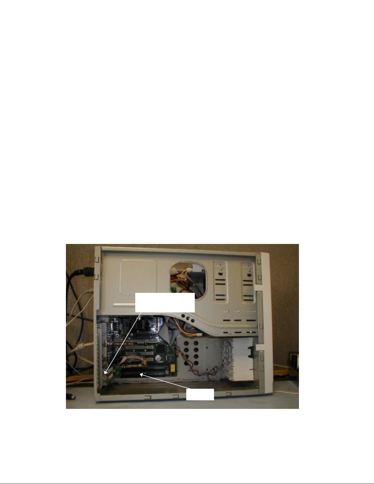
3. Note that two of the expansion port covers have been removed towards the bottom of the PC.
Remove the screws next to these s lots and retain for later installation. The ports at the back of the
SC3 Board Set will occupy these locations.
4. Note the ISA slots on the mother board of the PC. The board set will slide into the two bottom ISA
slots, which correspond with the open expansion port slots at the rear of the PC.
5. Remove the SC3 Board Sets from their packaging. It may help to lay the PC on its side before
installing the board set. Slide the ports through the open slots at the back of the PC, and slide the ISA
edge connectors into the ISA slots. Use a rocking motion to fully seat the ISA connectors in the slots.
6. Install the two screws which were removed during Step 3.
7. W hile the cover is off of the PC, press the video card, and sound card and Comm I/O Board (if
present) firmly into their connectors. Check that the memory SIMMs are firmly seated in their sockets.
Connections may have become unstable during shipment to your location.
8. Reinstall the cover on the PC, and reinstall any screws removed during Step 1.
Expansion Port Screws
(Steps 3 and 6)
ISA Slots
C36076 Rev. 9278
 Loading...