

Page 1
INSTRUCTIONS FOR RS-485 INTERFACE KIT, C06483
Locate and identify the following parts from the RS-485 Interface Kit. Hardware and quantities may vary.
QTY PART NO. DESCRIPTION
1 C06389 RS-485 I/F PCB
2 C08381 Standoff, M/F 6-32 3/4"
2 068843 Washer, #6 External Tooth
2 C08759 Screw, 6-32 x 3/8
1. Installing this kit involves DC wiring to the fuel management system. Read Sections 3 and 4 of the
Installation Manual
2. Turn off the circuit breakers supplying power to the MICRO, LIGHTS and FEED.
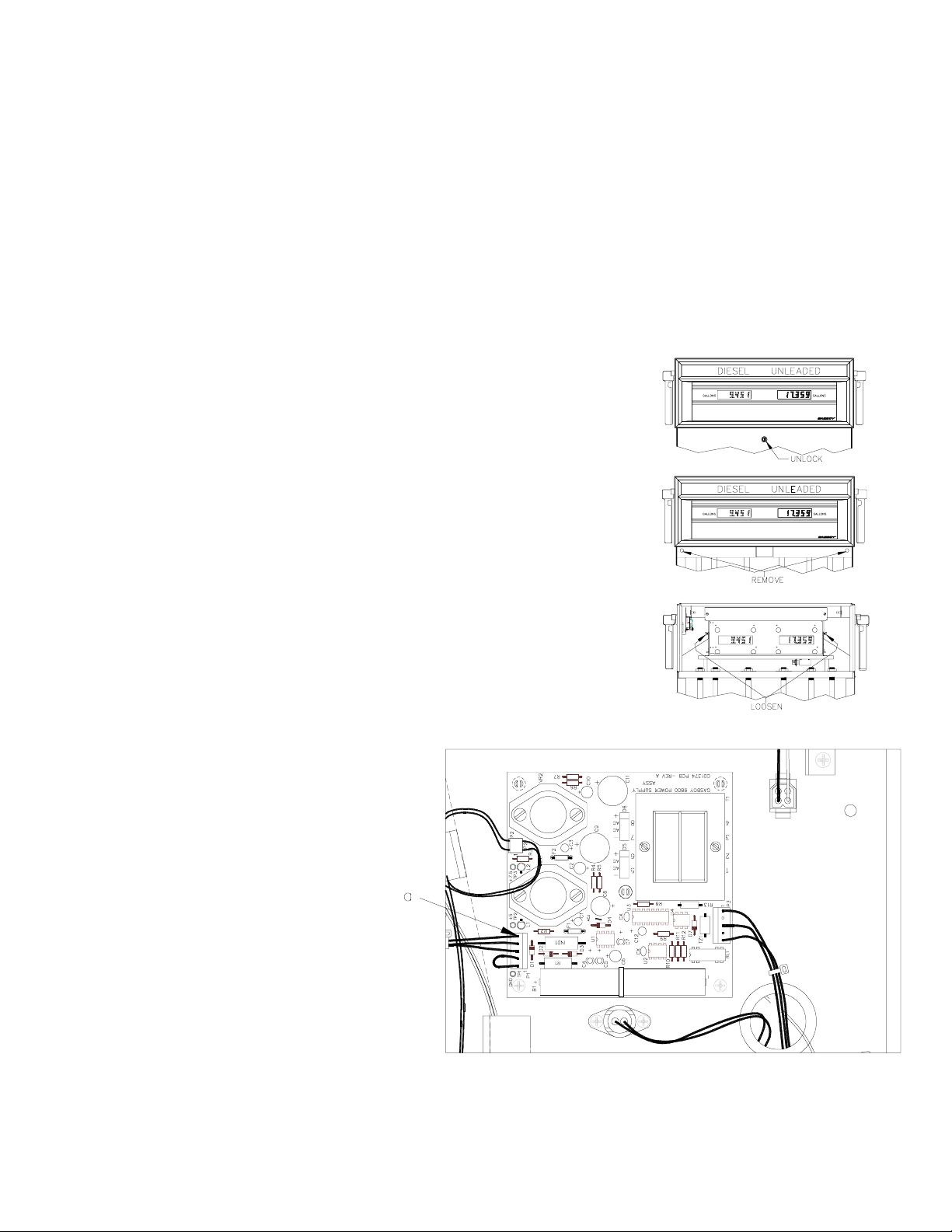
3. Unlock and remove the front panel.
4. Remove the two bolts located over the tabs of the bezel assembly. Lift the bezel
assembly upwards and out to remove.
5. Loosen, and remove if necessary, two screws located on the left and right door
support brackets and pivot the display panel down.
and your fuel management system
Installation Manual
before proceeding.
Pump/Dispenser
6. Pull the connector off P1 (a) on the
power supply. After a few seconds,
reconnect P1.
C35405 Rev. 8008 Page 1
Page 2
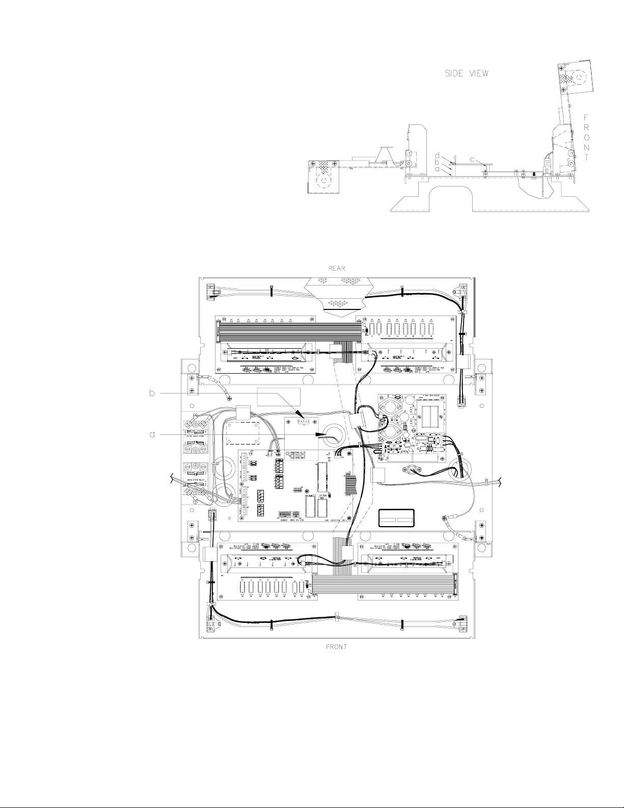
7. Slip the washers onto the threaded end of the
standoffs (a). Screw the standoffs (b) into the
platform base. (Newer platforms already have two
fixed standoffs (b); in which case, the loose
washers and standoffs are not used). Connect the
RS-485 PCB to P8 of the CPU PCB (c). Secure the
PCB using the two 6-32 screws (d).
8. Feed the DC cable up through the platform bushing (a). The DC cable is a 4-conductor gray cable with red, green,
white, and black wires terminated to a 5-position connector. It is part of the DC conduit assembly. Attach the DC cable
to P1 (b) of the RS-485 I/F PCB.
9. Complete the wiring between the card system and DC junction box as shown in the
10. Secure the display panel in the upright position.
11. Attach the bezel. Make sure the bezel is seated properly to insure a watertight seal.
12. Attach and lock the front panel.
Pump/Dispenser Installation Manual
Page 2 C35405 Rev. 8008
.
 Loading...