

Page 1
INSTALLING THE SUMP OVERFLOW CHECK VALVE
FOR Q SERIES SINGLE PUMPS
KIT #023900
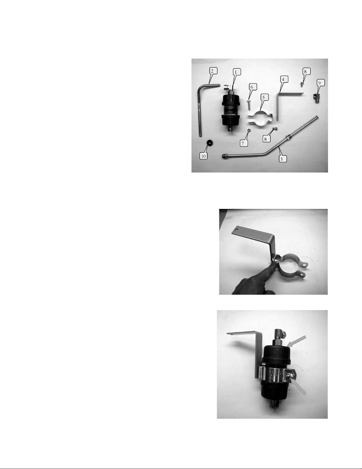
023900 Kit Contents
Item Part No. Description
1 023997 Assembly, Sump Overflow Check Valve
2 020701 Vent Tube
3 020700 Assembly, Vent Tube
4 015191 Bracket, Sump Overflow
5 020702 Hanger, Conduit Size, 1-1/2"
6 051866 Screw, 1/4-20 x 1-1/4 HHC Pl
7 038860 Nut, 1/4-20 Hex
8 053919 Screw, 1/4-20 x 1/2 HH Taptite
9 026044 Fitting, 3/8 Elbow, Inverted Flared
10 058021 Grommet
11 020897 Instruction shee t (this she et)
1. Turn off power to the p ump. Unlock and open the do or s . T r ip the s h ear va lv e’s pop p et to pr e ven t f uel f lo w in to
the pump.
2. Pre-assemble the co nduit hanger (item 5) to the bracket (item 4)
using a ¼-20 x ½ Tapt ite screw (item 8). (NOTE: use the hole
that is ½” from the edge.) (Figure 1)
3. Slide the sump over flow assembly (item 1) into the conduit
hanger. Using the ¼-20 x 1-1/4 screw (it em 6) and ¼” nut ( item
7) to secure the sump over flow assembly loosely in place.
(Figure 2)
Figure 1
Figure 2
020897 Rev. 06/12/03 Page 1
Page 2
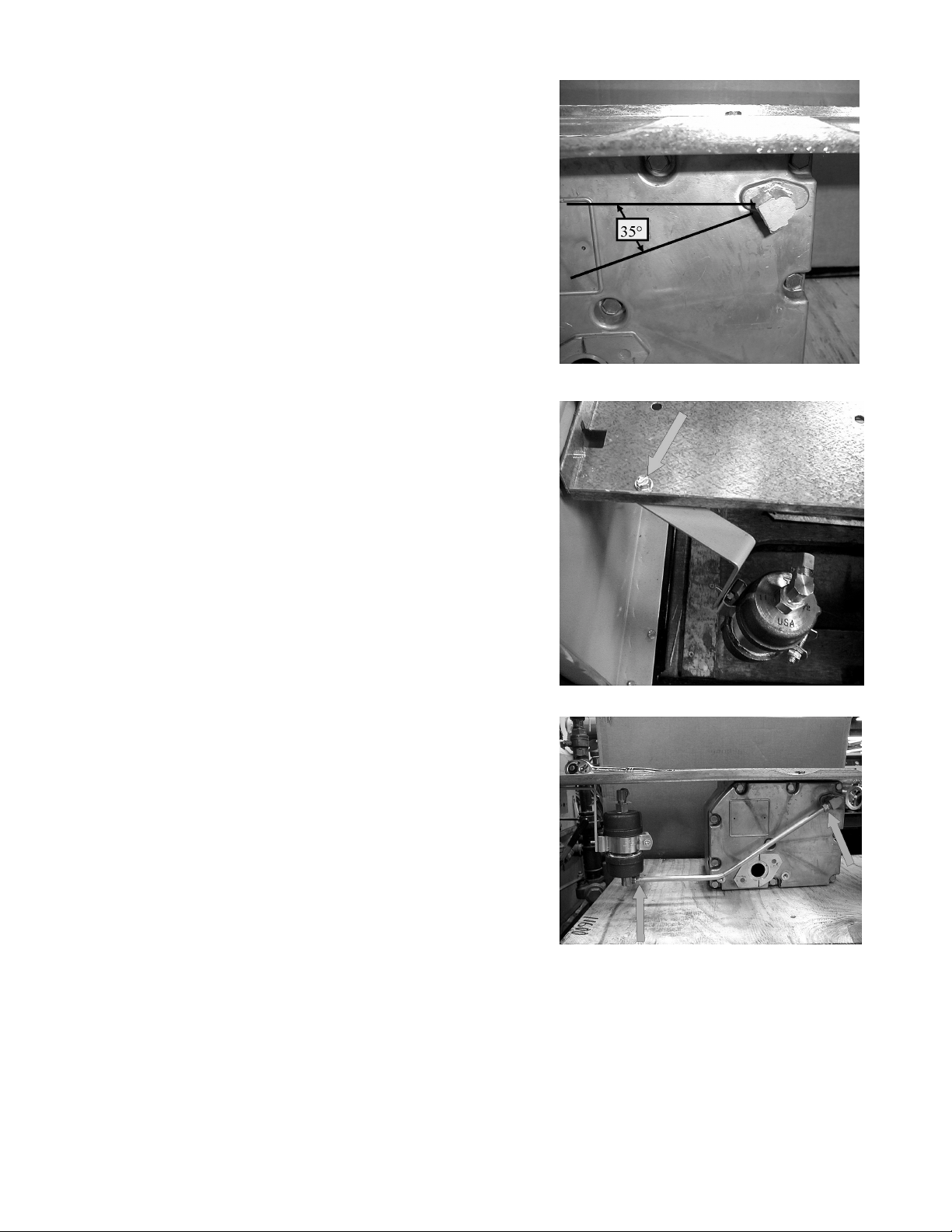
4. Behind the junction b ox, disconnect the exis ting vent tube and
remove the existing compression elbow in the pumping unit.
Install a 3/8” inverted f lared f ittin g (item 9) into the pumping un it
where the compress ion elbow just been removed. Rotate the
new fitting at about 35° as shown in Figure 3.
5. Install the pre-assembled unit from Step 3 onto the underside of
the motor/pump platform. Using a ¼-20 x ½ Taptite screw
(item 8, feed through an existing hole in the platform that is
close to the flange and the left side column. Secure the unit
loosely. (Figure 4)
Figure 3
6. Connect the vent tube assembly with flared nuts (item 3)
between the pumping unit’s elbo w and the bottom elbow of the
sump overflow assem bly (item 1). (Figure 5: NOT E: Junction
box removed for visibility.)
Figure 4
Figure 5
020897 Rev. 06/12/03 Page 2
Page 3

7. Install/insert the grom met (item 10) into the exis tin g vent hole in
the left side column (view from junction box side). (Figure 6)
8. Rem ove the com pres sion slee ve and com pr ession n ut fr om the
top elbow of sump overflow assembly (item 1), then preassemble the sleeve a nd nut over the vent tube as shown in
Figure 7.
Figure 6
9. Connect the pre-assembled vent tube to the compression
elbow and insert the other end into the grommet in the side
column. (Figure 8)
10. Tighten all loose connections. (Figure 9)
11. Tur n on po wer to t he pump. Open the shear val ve ’s pop pe t for
fuel flow into the pump. Close and lock the doors.
Figure 7
Figure 8
Figure 9
020897 Rev. 06/12/03 Page 3
 Loading...