

Page 1

FedEx Islander PLUS FMS
Installation Manual
MDE-5067
Page 2

Computer Programs and Documentation
Gasboy, Greensboro, is an ISO 9001:2000 registered facility.
Underwriters Laboratories (UL):
UL File# Products listed with UL
MH4314
All dispensers and self-contained pumping
units
MH10581 Key con t r o l u n i t , M o d e l G K E - B S e r i e s
Card reader terminals, Models 1000, 1000P
Site Controller, Model 2000S CFN Series
Data entry terminals, Model TPK-900 Series
Fuel Point Reader System
National Conference of Weights and Measures (NCWM) - Certificate of Compliance (CoC):
Gasboy pumps and dispensers are evaluated by NCWM under the National Type Evaluation Program (NTEP). NCWM has issued the following CoC:
CoC# Product Model # CoC# Product Model # CoC# Product Model #
95-179 Dispenser
9100 Retail Series, 8700
Series, 9700 Series
91-019 Dispenser
9100 Commercial
Series
05-002 Atlas
8700K, 8800K,
9100K, 9200K, 9800K
95-136 Dispenser 9800 Series 91-057 Controller
1000 Series FMS,
2000S-CFN Series
California Air Resources Board (CARB):
Executive Order # Product
G-70-52-AM Balance Vapor Recovery
G-70-150-AE VaporVac
Registered trademarks
ASTRA
®
Fuel Point
®
Gasboy
®
Keytrol
®
Slimline
®
Additional US and foreign trademarks pending.
Other brand or product names shown may be
trademarks or registered trademarks of their
respective holders.
Non-registered trademarks
Atlas
™
Consola
™
Infinity
™
Federal Communications Commission (FCC) Warning
All Gasboy computer programs (including software on diskettes and within memory chips) and documentation are copyrighted by, and shall remain the property of, Gasboy. Such
computer programs and documents may also contain trade secret information. The duplication, disclosure, modification, or unauthorized use of computer programs or
documentation is strictly prohibited, unless otherwise licensed by Gasboy.
This equipment has been tested and found to comply with the limits for a Class A digital device pursuant to Part 15 of the FCC Rules. These limits are designed to provide
reasonable protection against harmful interference when the equipment is operated in a commercial environment. This equipment generates, uses, and can radiate radio frequency
energy, and if not installed and used in accordance with the instruction manual, may cause harmful interference to radio communications. Operation of this equipment in a
residential area is likely to cause harmful interference in which case the user will be required to correct the interference at his own expense. Changes or modifications not expressly
approved by the manufacturer could void the user’s authority to operate this equipment.
Approvals
Trademarks
This document is subject to change without notice.
E-mail: literature@gasboy.com · Internet: http://www.gasboy.com
2013 GASBOY. All Rights Reserved.
Page 3

Table of Contents
Table of Contents
1 – Introduction 1-1
Purpose. . . . . . . . . . . . . . . . . . . . . . . . . . . . . . . . . . . . . . . . . . . . . . . . . . . . . . . . . . . . . . . . . . . . . . . . 1-1
Intended Users . . . . . . . . . . . . . . . . . . . . . . . . . . . . . . . . . . . . . . . . . . . . . . . . . . . . . . . . . . . . . . . . . . 1-1
Required Equipment . . . . . . . . . . . . . . . . . . . . . . . . . . . . . . . . . . . . . . . . . . . . . . . . . . . . . . . . . . . . . . 1-1
Abbreviations and Acronyms . . . . . . . . . . . . . . . . . . . . . . . . . . . . . . . . . . . . . . . . . . . . . . . . . . . . . . . 1-2
2 – Important Safety Information 2-1
3 – Installation Procedure 3-1
Before You Begin . . . . . . . . . . . . . . . . . . . . . . . . . . . . . . . . . . . . . . . . . . . . . . . . . . . . . . . . . . . . . . . . 3-1
Pre-installation Power Inspection. . . . . . . . . . . . . . . . . . . . . . . . . . . . . . 3-1
Pre-installation Checklist . . . . . . . . . . . . . . . . . . . . . . . . . . . . . . . . . . . . 3-2
Shutting Down Island. . . . . . . . . . . . . . . . . . . . . . . . . . . . . . . . . . . . . . . 3-3
Removing Existing Equipment. . . . . . . . . . . . . . . . . . . . . . . . . . . . . . . . 3-3
Mounting Dry Islander PLUS . . . . . . . . . . . . . . . . . . . . . . . . . . . . . . . . . 3-3
Installing FedEx Islander PLUS FMS . . . . . . . . . . . . . . . . . . . . . . . . . . . . . . . . . . . . . . . . . . . . . . . . . 3-6
Downloading Software. . . . . . . . . . . . . . . . . . . . . . . . . . . . . . . . . . . . . . 3-6
Installing Islander PLUS. . . . . . . . . . . . . . . . . . . . . . . . . . . . . . . . . . . . . 3-7
Connecting to FedEx Islander PLUS FMS Corporate Network. . . . . . 3-14
4 – SiteOmat Software Set Up 4-1
Software Set Up . . . . . . . . . . . . . . . . . . . . . . . . . . . . . . . . . . . . . . . . . . . . . . . . . . . . . . . . . . . . . . . . . 4-1
Process Check. . . . . . . . . . . . . . . . . . . . . . . . . . . . . . . . . . . . . . . . . . . . 4-1
OrCU Set Up . . . . . . . . . . . . . . . . . . . . . . . . . . . . . . . . . . . . . . . . . . . . . 4-4
Setting SiteOmat. . . . . . . . . . . . . . . . . . . . . . . . . . . . . . . . . . . . . . . . . . . . . . . . . . . . . . . . . . . . . . . . . 4-6
Pump Configuration . . . . . . . . . . . . . . . . . . . . . . . . . . . . . . . . . . . . . . . . . . . . . . . . . . . . . . . . . . . . . 4-17
Tank Configuration . . . . . . . . . . . . . . . . . . . . . . . . . . . . . . . . . . . . . . . . . . . . . . . . . . . . . . . . . . . . . . 4-20
Setting Fuel Price . . . . . . . . . . . . . . . . . . . . . . . . . . . . . . . . . . . . . . . . . . . . . . . . . . . . . . . . . . . . . . . 4-23
Unblocking or Activating Pumps . . . . . . . . . . . . . . . . . . . . . . . . . . . . . . . . . . . . . . . . . . . . . . . . . . . . 4-24
Weights & Measures (W&M) Dongle Activation Procedure . . . . . . . . . . . . . . . . . . . . . . . . . . . . . . . 4-26
Process Check. . . . . . . . . . . . . . . . . . . . . . . . . . . . . . . . . . . . . . . . . . . 4-29
Synchronizing with Fleet Head Office (FHO) . . . . . . . . . . . . . . . . . . . . . . . . . . . . . . . . . . . . . . . . . . 4-30
HOCOMM User . . . . . . . . . . . . . . . . . . . . . . . . . . . . . . . . . . . . . . . . . . 4-30
Synchronizing FedEx Islander PLUS FMS . . . . . . . . . . . . . . . . . . . . . 4-32
Test Sequences . . . . . . . . . . . . . . . . . . . . . . . . . . . . . . . . . . . . . . . . . . . . . . . . . . . . . . . . . . . . . . . . 4-33
Testing Procedure for Pumps . . . . . . . . . . . . . . . . . . . . . . . . . . . . . . . 4-33
Finalizing Installation. . . . . . . . . . . . . . . . . . . . . . . . . . . . . . . . . . . . . . . . . . . . . . . . . . . . . . . . . . . . . 4-33
Appendix A: Commissioning A-1
Appendix B: Multiple Controller Sites B-1
Installing Multiple Controller FedEx Islander PLUS FMS . . . . . . . . . . . . . . . . . . . . . . . . . . . . . . . . . . B-1
Gasboy 9800 Series Pumps Business Inventory Reconciliation (BIR) Set Up . . . . . . . . . . . . . . . . . . B-2
MDE-5067 FedEx Islander PLUS FMS Installation Manual · March 2013 Page i
Page 4

Table of Contents
Appendix C: FedEx Project Site Information Form (Example Only) C-1
Index Index-1
Page ii MDE-5067 FedEx Islander PLUS FMS Installation Manual · March 2013
Page 5

Purpose Introduction
Verify that you have all the required equipment and software to complete the installation.
IMPORTANT INFORMATION
1 – Introduction
Purpose
This manual provides instructions for installing the FedEx Islander PLUS Fuel Management
System (FMS) in the off-site server.
Intended Users
This manual is intended for facility personnel (Operations Manager) who installs the FedEx
Islander PLUS FMS.
Required Equipment
Following equipment is required to install the FedEx Islander PLUS FMS:
• FedEx Custom Islander PLUS FMS (PA039400801FX)
• Contents of the FedEx project folder from ftp.gilbarco.com:
- Board Support Package (BSP) - Version 1.08 Service Pack 8
- SiteOmat - Version 6.4.33.098
- Payment Application Interface Service (P
Note: To report any missing or damaged equipment, contact Bob Grif
AIS) - 4.31.1.58
fith at 1-336-547-5654.
MDE-5067 FedEx Islander PLUS FMS Installation Manual · March 2013 Page 1-1
Page 6

Introduction Abbreviations and Acronyms
Abbreviations and Acronyms
Term Description
BIR Business Inventory Reconciliation
BSP Board Support Package
DEF Diesel Exhaust Fluid
DNS Domain Name System
FHO Fleet Head Office
FMS Fuel Management System
GW Gateway
HOCOMM Head Office Communicator
LAN Local Area Network
OrCU Orpak Controller Unit
OrPT Orpak Payment Terminal
OS Operating System
PAIS Payment Application Interface Service
POE Power Over Ethernet
STP Submersible Turbine Pump
WAN Wide Area Network
W&M Weights & Measures
Page 1-2 MDE-5067 FedEx Islander PLUS FMS Installation Manual · March 2013
Page 7
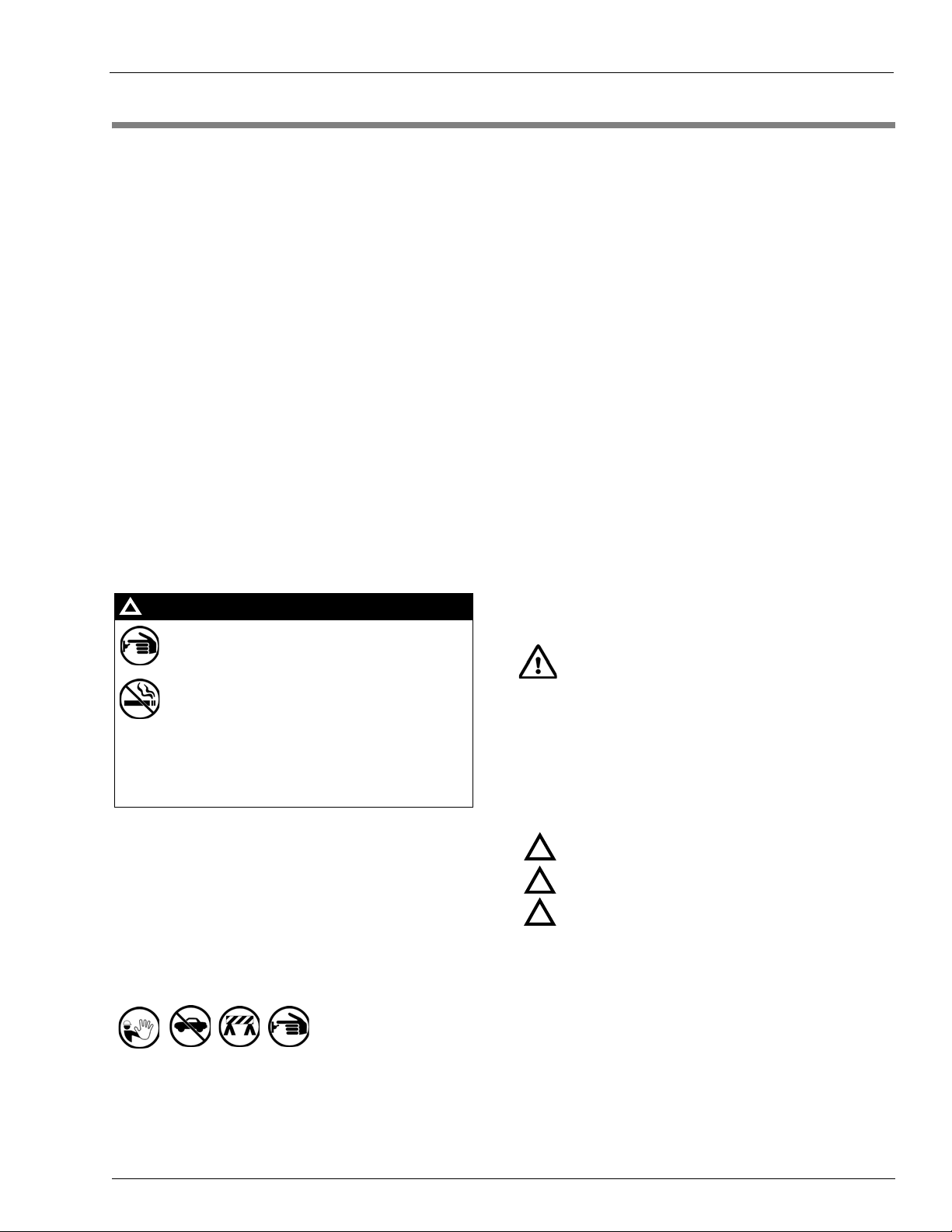
2 – Important Safety Information
The EMERGENCY STOP, ALL STOP, and
PUMP STOP buttons at the cashier’s station
WILL NOT shut off electrical power to the
pump/dispenser. This means that even if you
activate these stops, fuel may continue to flow
uncontrolled.
You must use the TOTAL ELECTRICAL
SHUT-OFF in the case of an emergency and not
the console’s ALL STOP and PUMP STOP or
similar keys.
!
WARNING
!
Important Safety Information
Note: Although DEF is non-flammable, Diesel is
flammable. Therefore, for DEF cabinets that are
attached to Diesel dispensers, follow all the notes
in this section that pertain to flammable fuels.
This section introduces the hazards and safety precautions
associated with installing, inspecting, maintaining or servicing
this product. Before performing any task on this product, read
this safety information and the applicable sections in this
manual, where additional hazards and safety precautions for
your task will be found. Fire, explosion, electrical shock or
pressure release could occur and cause death or serious injury,
if these safe service procedures are not followed.
Preliminary Precautions
You are working in a potentially dangerous environment of
flammable fuels, vapors, and high voltage or pressures. Only
trained or authorized individuals knowledgeable in the related
procedures should install, inspect, maintain or service this
equipment.
Emergency Total Electrical Shut-Off
The first and most important information you must know is how
to stop all fuel flow to the pump/dispenser and island. Locate
the switch or circuit breakers that shut of f all p ower to all fueling
equipment, dispensing devices, and Submerged Turbine
Pumps (STPs).
Read the Manual
Read, understand and follow this manual and any other labels
or related materials supplied with this equipment. If you do not
understand a procedure, call a Gilbarco Authorized Se rvice
Contractor or call the Gilbarco Support Ce nte r at
1-800-800-7498. It is imperative to your safety and the sa fety of
ot
hers to understand the procedures before beginning work.
Follow the Regulations
Applicable information is available in National Fire Protection
Association (NFPA) 30A; Code for Motor Fuel Dispensing
Facilities and Repair Garages, NFPA 70; National Electrical
Code (NEC), Occupational Safety and Health Administration
(OSHA) regulations and federal, state, and local codes. All
these regulations must be followed. Failure to install, inspect,
maintain or service this equipment in accordance with these
codes, regulations and standards may lead to legal citations
with penalties or affect the safe use and operat ion of the
equipment.
Replacement Parts
Use only genuine Gilbarco replacement parts and retrofit kits on
your pump/dispenser. Using parts other than genuine Gilbarco
replacement parts could create a safety hazard and violate
local regulations.
Safety Symbols and Warning Words
This section provides important information about warn ing
symbols and boxes.
Alert Symbol
Total Electrical Shut-Off Before Access
Any procedure that requires access to electrical co mponent s or
the electronics of the dispenser requires total electrical shut off
of that unit. Understand the function and location of this switch
or circuit breaker before inspecting, installing, maintaining, or
servicing Gilbarco equipment.
Evacuating, Barricading and Shutting Off
Any procedure that requires access to the pump/dispenser or
STPs requires the following actions:
• An evacuation of all unauthorized persons and vehicles from
the work area
• Use of safety tape, cones or barrica
• A total electrical shut-off of the affected unit(s)
MDE-5067 FedEx Islander PLUS FMS Installation Manual · March 2013 Page 2-1
des at the affected unit(s)
This safety alert symbol is used in this manual and on
warning labels to alert you to a precaution which must be
ed to prevent potential personal safety hazards. Obey
follow
safety directives that follow this symbol to avoid possible injury
or death.
Signal Words
These signal words used in this manual and on warning labels
tell you the seriousness of particular safety hazards. The
precautions below must be followed to prevent death, injury or
damage to the equipment:
s
DANGER: Alert
!
which will result in death or serious injury.
WARNING: A
!
that could result in death or serious injury.
CAUTION with Alert
!
unsafe practice which may result in minor injury.
CAUTION without Alert symbol: Designates a hazard or
un
safe practice which may result in property or
equipment damage.
you to a hazard or unsafe practice
lerts you to a hazard or unsafe practice
sy
mbol: Designates a hazard or
Working With Fuels and Electrical Energy
Prevent Explosions and Fires
Fuels and their vapors will explode or burn, if ignited. Spilled or
leaking fuels cause vapors. Even filling customer tanks will
cause potentially dangerous vapors in the vicinity of the
dispenser or island.
DEF is non-flammable. Therefore, explosion and fire safety
rnings do not apply to DEF fluid lines.
wa
Page 8
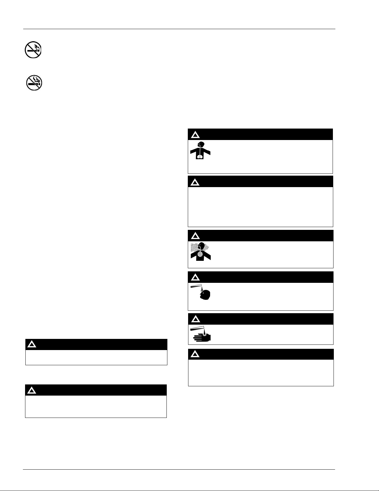
Important Safety Information
The pump/dispenser contains a chemical known to the
State of California to cause cancer.
WARNING
!
The pump/dispenser contains a chemical known to the
State of California to cause birth defects or other
reproductive harm.
WARNING
!
Gasoline/DEF ingested may cause
unconsciousness and burns to internal organs.
Do not induce vomiting. Keep airway open.
Oxygen may be needed at scene. Seek medical
advice immediately.
DEF generates ammonia gas at high er temperatures.
When opening enclosed panels, allow the unit to air out to
avoid breathing vapors.
If respiratory difficulties develop, move victim away from
source of exposure and into fresh air. If symptoms persist,
seek medical attention.
WARNING
!
WARNING
!
Gasoline inhaled may cause unconsciousness
and burns to lips, mouth and lungs.
Keep airway open.
Seek medical advice immediately.
WARNING
!
Gasoline/DEF spilled in eyes may cause burns to
eye tissue.
Irrigate eyes with water for approximately
15 minutes. Seek medical advice immediately.
WARNING
!
Gasoline/DEF spilled on skin may cause burn s.
Wash area thoroughly with clear water.
Seek medical advice immediately.
WARNING
!
DEF is mildly corrosive. Avoid contact with eyes, skin, and
clothing. Ensure that eyewash stations and safety
showers are close to the work location. Seek medical
advice/recommended treatment if DEF spills into eyes.
WARNING
!
No Open Fire
Open flames from matches, lighters, welding torches or
other sources can ignite fuels and their vapors.
No Sparks - No Smoking
Sparks from starting vehicles, starting or using power tools,
burning cigarettes, cigars or pipes can also ignite fuels and
their vapors. Static electricity, including an electrostatic charge
on your body , can ca use a sp ark su f ficient to ign ite fuel vapors.
Every time you get out of a vehicle, touch the metal of your
vehicle, to discharge any electrostatic charge before you
approach the dispenser island.
Working Alone
It is highly recommended that someone who is capable of
rendering first aid be present during servicing. Familiarize
yourself with Cardiopulmonary Resuscitation (CPR) methods, if
you work with or around high voltages. This information is
available from the American Red Cross. Always advise the
station personnel about where you will be working, and caution
them not to activate power while you are working on the
equipment. Use the OSHA Lockout/Tagout procedures. If you
are not familiar with this requirement, refer to this information in
the service manual and OSHA documentation.
In an Emergency
Inform Emergency Personnel
Compile the following information and inform emergency
personnel:
• Location of accident (for example, addres
building, and so on)
• Nature of accident (for example, poss
over by car , burns, and so on)
• Age of victim (for example, baby, teenager, middle-age,
elderly
)
• Whether or not victim has receiv
ed f
stopped bleeding by pressure, and so on)
• Whether or not a victim has vomited (for example, if
swal
lowed or inhaled something, and so on)
s, front/back of
ible heart attack, run
irst aid (for example,
Working With Electricity Safely
Ensure that you use safe and established practices in workin g
with electrical devices. Poorly wired devices may cause a fire,
explosion or electrical shock. Ensure that grounding
connections are properly made. Take care that sealing devices
and compounds are in place. Ensure that you do not pinch
wires when replacing covers. Follow OSHA Lockout/Tagout
requirements. Station employees and service con tra ctors need
to understand and comply with this program completely to
ensure safety while the equipment is down.
Hazardous Materials
Some materials present inside electronic enclosures may
present a health hazard if not handled correctly. Ensure that
you clean hands after handling equipment. Do not place any
equipment in the mouth.
Page 2-2 MDE-5067 FedEx Islander PLUS FMS Installation Manual · March 2013
IMPORTANT: Oxygen may be needed at scene if gasoline has
been ingested or inhaled. Seek medical advice immediately.
Lockout/Tagout
Lockout/Tagout covers serv icing and maintenance o f machines
and equipment in which the unexpected energization or
ipme
start-up of the machine(s) or equ
nt or release of stored
energy could cause injury to employ ee s or personnel.
Lockout/Tagout applies to all mechanical, hydraulic, chemical,
or o
ther energy , but does not cover electrical hazards.
Subpart S of 29 CFR Part 1910 - Electrical Hazards, 29 CFR
Part 19
10.333 contains specific Lockout/Tagout provision for
electrical hazards.
Page 9
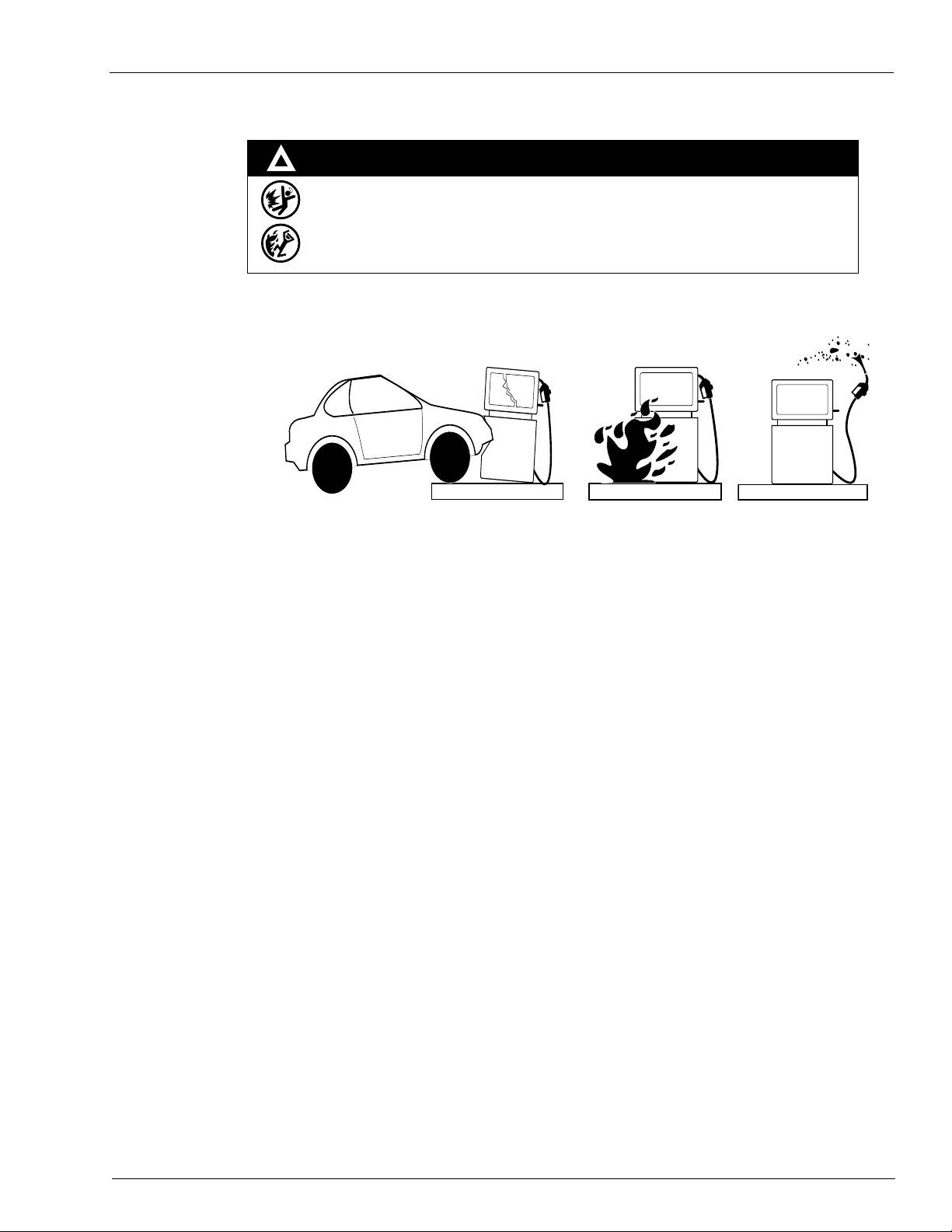
Hazards and Actions
WARNING
Spilled fuels, accidents involving pumps/dispensers, or uncontrolled fuel flow create a
serious hazard.
Fire or explosion may result, causing serious injury or death.
Follow established emergency procedures.
DEF is non-flammable. However it can create a slip hazard. Clean up spills promptly.
!
Collision of a Vehicle with Unit Fire at Island Fuel Spill
The following actions are recommended regarding these hazards:
Important Safety Information
• Do not go near a fuel spill or allow anyone else in the area.
• Use station EMERGENCY CUTOFF immediately. T urn of f all
• Do not use console E-STOP, ALL STOP, and PUMP STOP to shut off power. These keys do not
ve AC power and do not always stop product flow.
remo
• Take precautions to avoid igniting fuel. Do not allow starting of vehicles in the area. Do not allow
open flames, smoking or power tools in the area.
• Do not expose yourself to hazardous conditions such as fire, spil
• Call emergency numbers.
system circuit breakers to the island(s).
led fuel or exposed wiring.
MDE-5067 FedEx Islander PLUS FMS Installation Manual · March 2013 Page 2-3
Page 10

Important Safety Information
This page is intentionally left blank.
Page 2-4 MDE-5067 FedEx Islander PLUS FMS Installation Manual · March 2013
Page 11
3 – Installation Procedure
AC power is present on the Terminal Blocks in the pedestal. Electrical shock may occur if
the operator comes in contact with these connections.
WARNING
If any readings are NOT within the acceptable ranges, then STOP. For further instructions,
call Gasboy TAC at 1-800-444-5529.
IMPORTANT INFORMATION
Before You Begin
Use the following checklist to verify you have all the required equipment to complete the
installation.
Pre-installation Power Inspection
Installation and reliability issues during the initial roll out of the FedEx project have revealed a
high number of sites with electrical issues, excessive noise, due to improper system and panel
grounding, and other issues. These issues have made it necessary to verify the quality of the
AC power at the island before removing the existing equipment and checking again post
installation to verify no issues have been introduced during the installation process.
These checks/tests are simple to complete and must not add
entire installation.
Following checks/tests pre-install are designed to identify additional work required, not
currently part of the installation scope.
1 Verify that the AC Power for the Islander PLUS System comes from a separate, dedicated
circuit breaker. No other equipment must be powered from this breaker. The system’s pumps
or dispensers must not be on this breaker. Power for the system must be 115 VAC + 10%,
47-63 HZ. The system draws 135 watts
Before You Begin
more than 10-15 minutes to the
maximum.
2
Locate the SYSTEM POWER Terminal Block in the pedestal on the existing system. Use a
digital AC voltmeter to measure the following voltages.
Hot to Neutral measured at: ____________ (fill in value) measured by: ____________ (print name)
This voltage must be 115 VAC + 10% (104 VAC to 126 VAC).
Hot to Ground measured at: ____________ (fill in value) measured by: ____________ (print name)
This voltage must be 115 VAC + 10% (104 VAC to 126 VAC).
Neutral to Ground measured at: ____________ (fill in value) measured by: ____________ (print name)
This voltage must be 0 VAC + 500 millivolts (-500 mV to 500 mV).
Note: If power is not within these specifications,
3
Put ALL PUMPS into manual override and activate the pumps [ensure Submersible Turbine
correct it before continuing.
Pumps (STPs)/pumping units are ON]. Use a digital AC voltmeter to measure the following
voltages
Hot to Neutral measured at: ____________ (fill in value) measured by: ____________ (print name)
This voltage must be 115 VAC + 10% (104 VAC to 126 VAC).
Hot to Ground measured at: ____________ (fill in value) measured by: ____________ (print name)
This voltage must be 115 VAC + 10% (104 VAC to 126 VAC).
Neutral to Ground measured at: ____________ (fill in value) measured by: ____________ (print name)
This voltage must be 0 VAC + 500 millivolts (-500 mV to 500 mV).
.
Note: If power is not within these specifications, correct it before continuing.
MDE-5067 FedEx Islander PLUS FMS Installation Manual · March 2013 Page 3-1
Page 12
Before You Begin
DO NOT remove existing system before verifying that there are NO BARRIERS to
complete the Islander PLUS installation.
If issues are found, call Bob Griffith at 336-547-5654 IMMEDIATELY to discuss optio ns.
WARNING
4 Grounding Method: Proper system grounding is an extremely important part of the system
installation. Grounds for all system devices must be wired to the breaker panel ground bus bar
which, in turn, must be grounded to a ground rod. A conduit ground does not provide a
sufficient ground. It is recommended that the neutral and ground bus bars be bonded together
unless prohibited by local codes.
Pre-installation Checklist
Following pre-installation checklist is designed to ensure proper installation:
Description Checkbox
Check that you have the correct Gasboy Supplied parts:
• PA093400810FX - Islander PLUS FedEx CUSTOM.
• Stage 2 FedEx Islander PLUS Install Guide.
Check the conduit layout, and ensure you have the proper supplies and
clearances to complete the installation.
Check all fueling positions for proper operation.
Check all hose reels for proper operation - All hose reels connected to the
existing system MUST be connected and controlled by the Gasboy Fleet
PLUS system.
Check the E-STOP system for proper operation.
Find the circuit controlling the current FMS. Verify this is a dedicated
circuit.
Trace and identify control wires in the existing system.
Know the function of the control wires.
Identify and label the handle switch (in-use), if available.
Identify and label the (line/load) or authorize wires.
Identify and label the pulser wires.
Identify and label the LAN/WAN connections.
Mark all control wires for use when installing the Islander PLUS system.
Page 3-2 MDE-5067 FedEx Islander PLUS FMS Installation Manual · March 2013
Page 13

Shutting Down Island
For issues locating the FedEx Fleet Manager, contact Travis Langston at 1-870-704-5230.
IMPORTANT INFORMATION
The circuit panel must be locked out, tagged out as per normal Gilbarco® safety procedures
found in the Gilbarco LMS training module http://wise.gilbarco.com. For more information,
refer to GVRSAFEUS50-012 GVR Fueling Site Safety.
CAUTION
Ensure that the facility personnel (Operations Manager) is aware of these steps before the old
equipment is removed. Name and contact information for the Operations Manager and site
installation parameters will be sent to you by Bob Griffith (1-336-547-5654).
FedEx Project Site Information Form, includes the following [for an example, refer to “FedEx
Project Site Information Form (Example Only)” on page C-1]:
• Operations Manager’s Name and Phone Number.
• Fipay Server IP Address, Subnet Mask, and Gateway IP Address.
• SiteOmat Wide Area Network [WAN Local Area Network (LAN2)] IP Address, Subnet
Mask, a
• FedEx Alpha code - SiteOmat St
• Site Number - SiteOmat Station Code.
Before You Begin
nd Gateway IP Address.
ation Name or Description.
Removing Existing Equipment
The Gasboy Fleet PLUS system will use some of the same control and communication wiring
as other third-party FMS. To aid in efficient installation, all control wiring in an existing
system must be labeled before disconnection.
Mounting Dry Islander PLUS
To mount the Islander PLUS in the facility, proceed as follows:
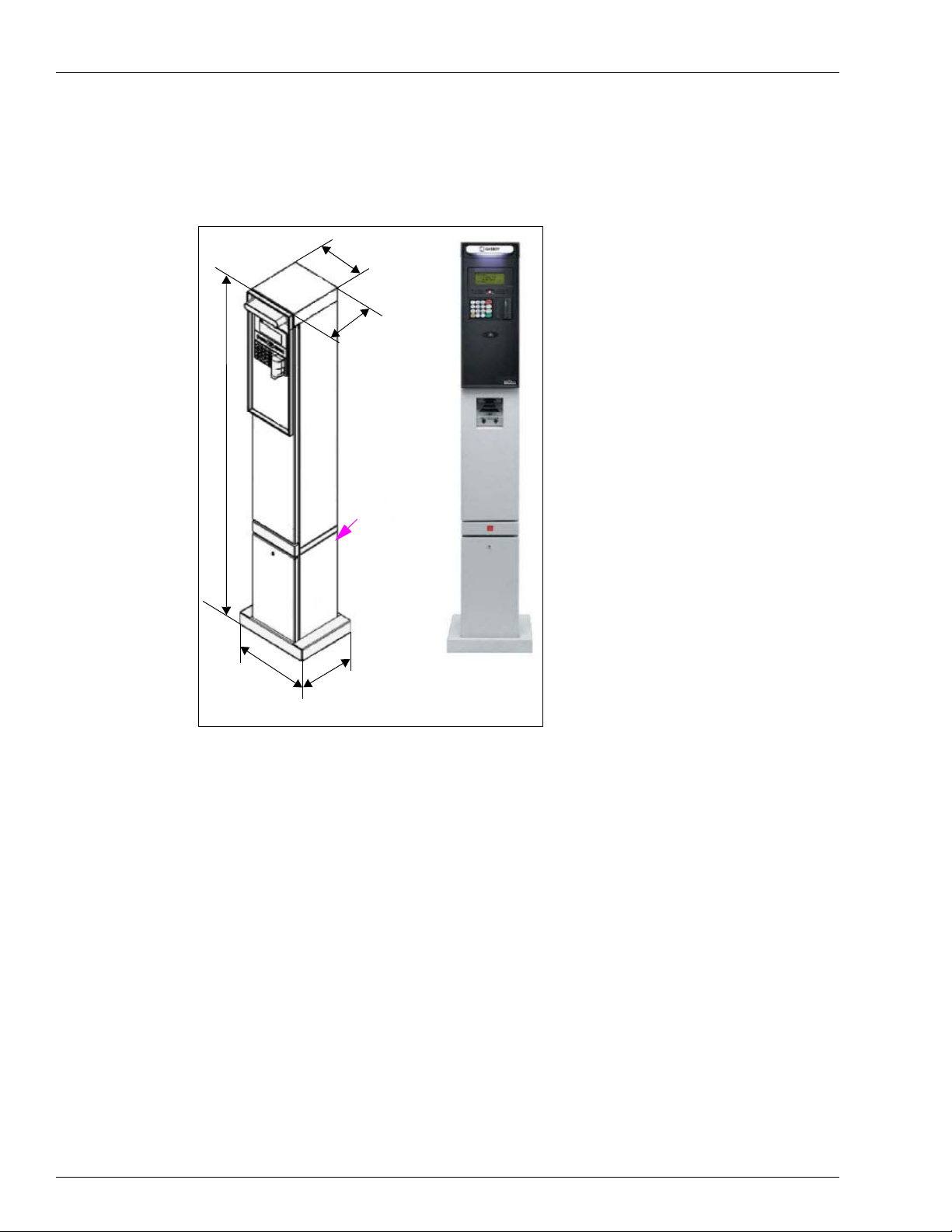
1 When installing the Gasboy Islander PLUS at a facility with existing conduits at the fuel
island, it is important to note the dimensions of the pedestal to determine if special fabrication
is required for the conduits (see Figure 3-1 on page 4).
2 The pedestal can be cut within UL parameters from the base plate up to 18 inches. Any holes
drilled in the pedestal must only be large enough to fit conduit elbows and must not be inserted
above the IS Barrier Plate.
3 Following conduits are required for the Gasboy Islander PLUS pedestal:
• High Voltag e (AC power, pump control, ground, in-use for me
• Low Volta ge (pulser, tank gauge, and LAN).
chanical dispensers).
MDE-5067 FedEx Islander PLUS FMS Installation Manual · March 2013 Page 3-3
Page 14
Before You Begin
9
.1
7
3
9
.4
8
8
61.728
1
3
.6
5
4
1
0
.
7
0
1
I/S Barrier Plate
Note: Dimensions are in inches.
4 Depending on the installation, you may need to modify the existing conduit wiring to
accommodate the required feeds.
Figure 3-1: Installing Gasboy Islander PLUS
Page 3-4 MDE-5067 FedEx Islander PLUS FMS Installation Manual · March 2013
Page 15
Before You Begin
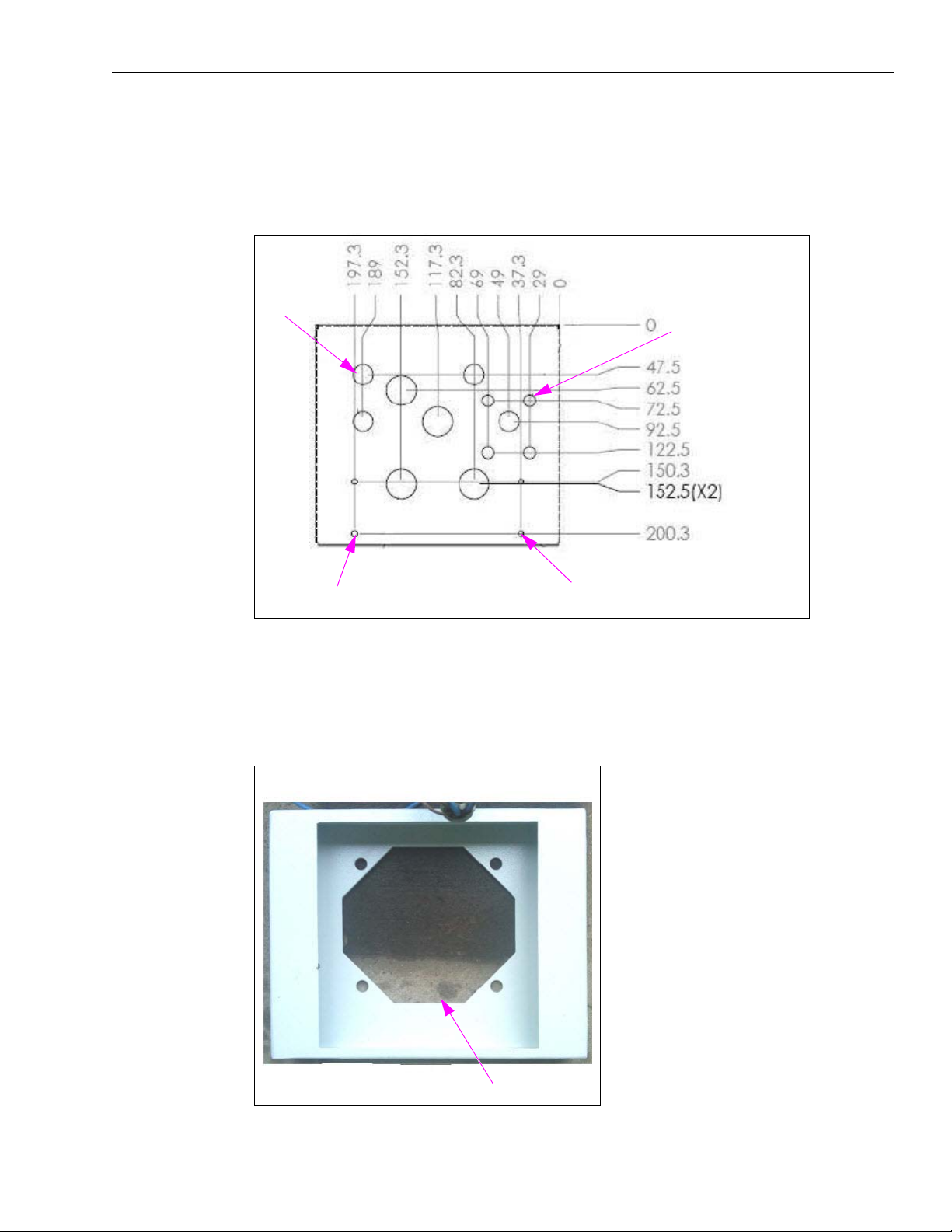
A3
φ 11 (X4)
With Knockout Cover
φ Insert PEM CLS-M4X1
From Other Side (X4)
A3 φ 28.5 (X4) With Knockout Cover
Front of Base - Wide Side
Wide Side
5 Make a template of the conduit configuration for the cutouts in the barrier plate. The cutouts in
the plate must only be cut large enough for the wiring to be pulled through. You will also want
to install conduit gaskets to prevent wire damage (see Figure 3-2).
Figure 3-2: Conduit Configuration in Barrier Plate
6 After the pedestal and conduit needs are addressed, place the base plate over the conduits,
wider side faced towards the front of the unit, and mark the island along the outside edge of the
base plate as well as the inside holes for the lag bolt placement (see Figure 3-3).
Figure 3-3: Base Plate on Conduits
MDE-5067 FedEx Islander PLUS FMS Installation Manual · March 2013 Page 3-5
Page 16
Installing FedEx Islander PLUS FMS
Installing FedEx Islander PLUS FMS
To install the FedEx Islander PLUS FMS, proceed as follows:
Downloading Software
To download the software, proceed as follows:
1 Download all software and documents required for installation:
•Site: ftp.gilbarco.com
• ID: -
• Password: -
Note: If the ID and Password are not known, contact Gasboy TAC at 1-800-444-5529.
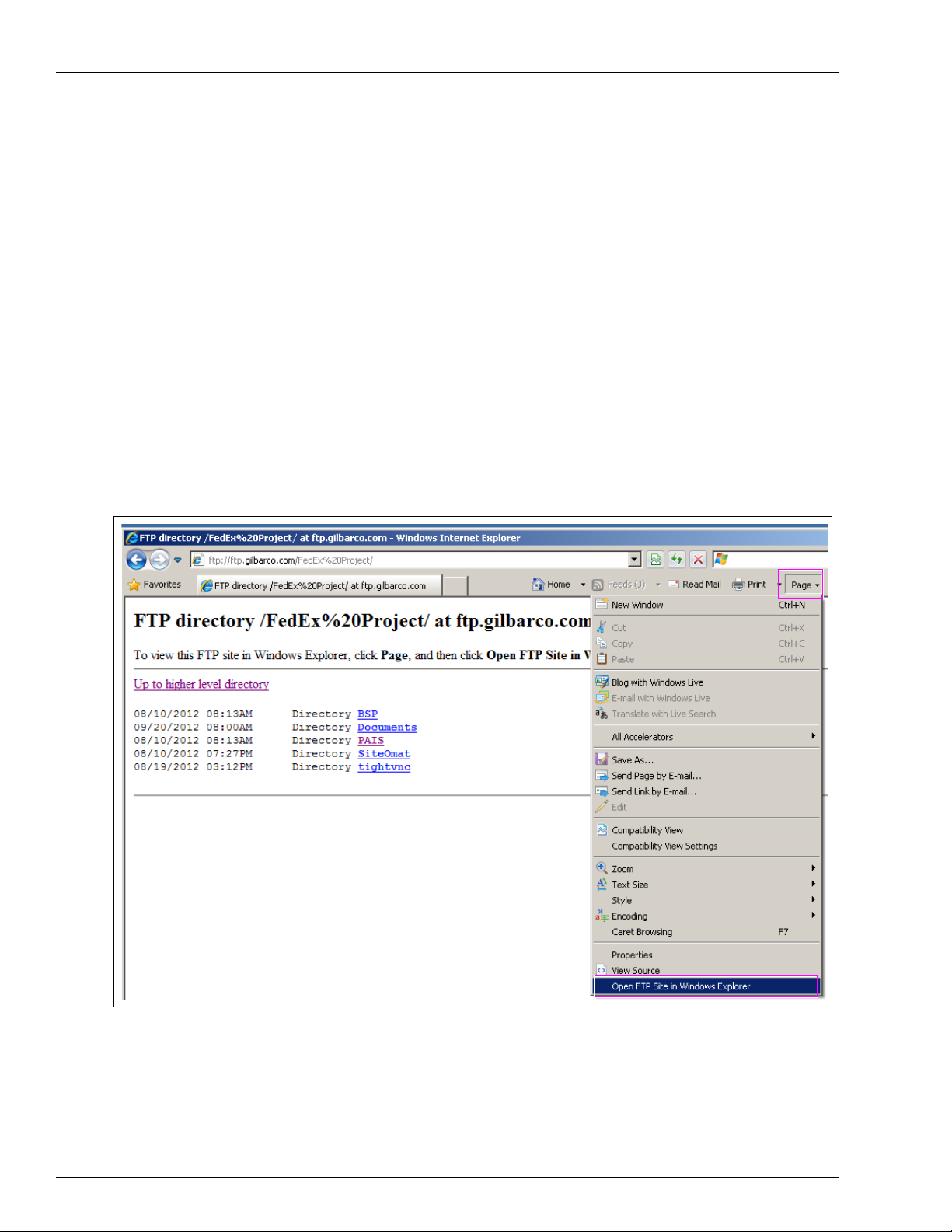
2 Navigate to the FedEx folder and download the entire contents of this folder.
3 Click the Page button and select Open FTP Site in Internet Explorer
Figure 3-4: Opening FTP Site in Internet Explorer
®
.
Page 3-6 MDE-5067 FedEx Islander PLUS FMS Installation Manual · March 2013
Page 17
Installing Islander PLUS
To install the Islander PLUS, proceed as follows:
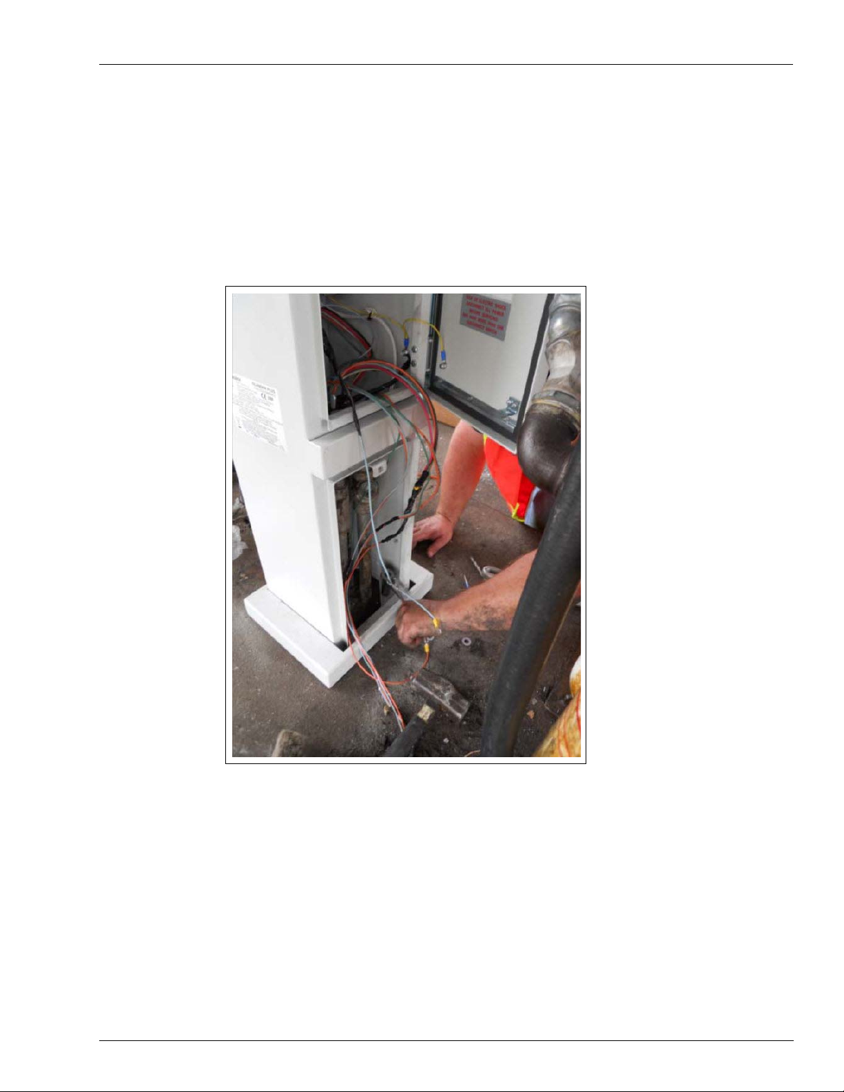
1 After lag bolts are inserted in the island, position the base plate over the lag bolts, wide-side
facing front. The pedestal is then placed over conduit and into the base plate. To avoid
pinching wires, two technicians are required for this step. Tighten the nuts over the lag bolts to
secure to the island (see Figure 3-5).
Figure 3-5: Installing Islander PLUS
Installing FedEx Islander PLUS FMS
MDE-5067 FedEx Islander PLUS FMS Installation Manual · March 2013 Page 3-7
Page 18
Installing FedEx Islander PLUS FMS
PCB Assembly P.S-24 VDC
[8-hose (M09680B083)]
PCB Assembly, SSR
[8-hose (M09680B084)]
(i)
(ii)
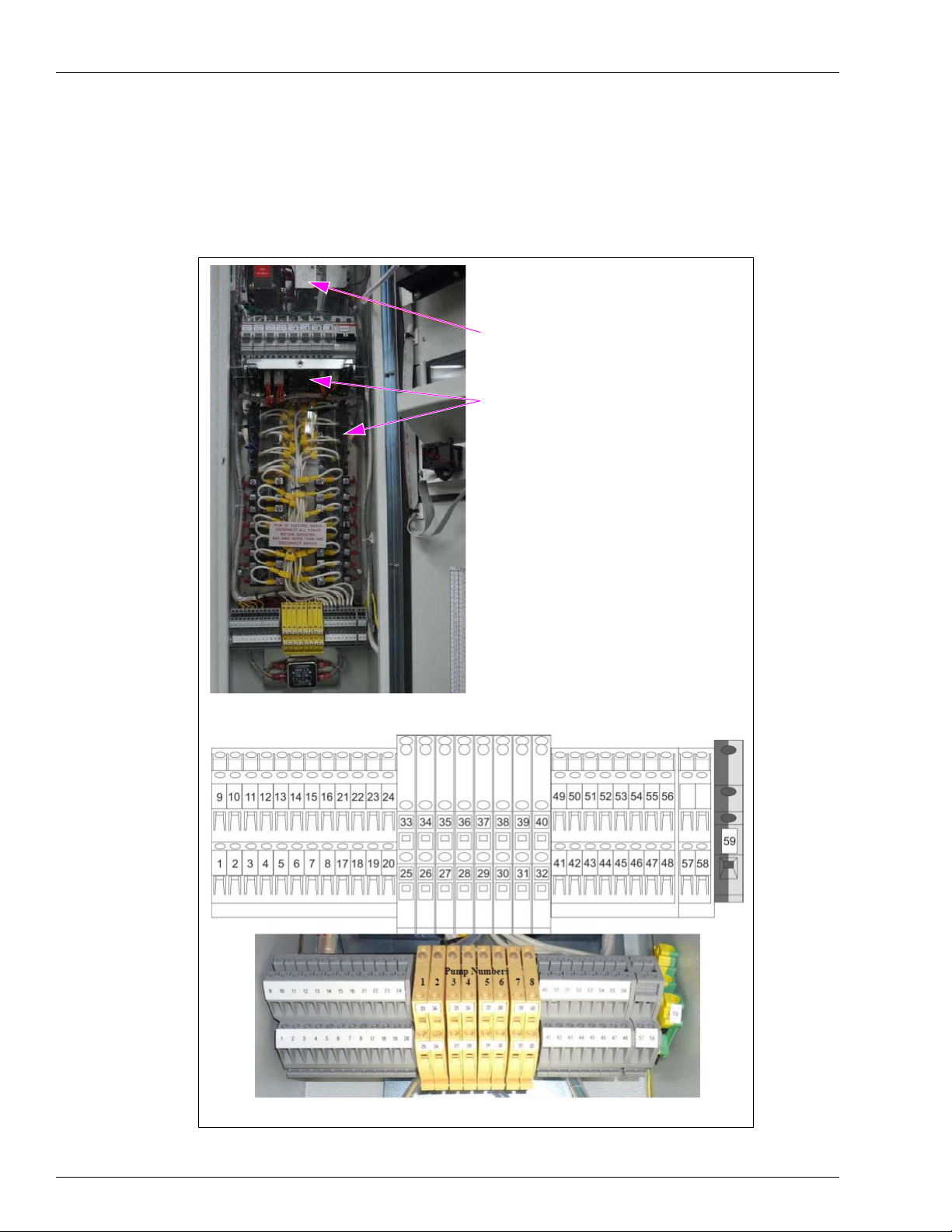
2 The control wiring must be attached to the Terminal Block after the pedestal is secure
(see Figure 3-6). System power, dispenser communication,
connected based on the Terminal
(see Figure 3-8 on page 10).
Figure 3-6: Connecting Control Wiring to Terminal Block
LAN, and so on, must be
Block diagram on the inside door of the pedestal
Page 3-8 MDE-5067 FedEx Islander PLUS FMS Installation Manual · March 2013
Page 19
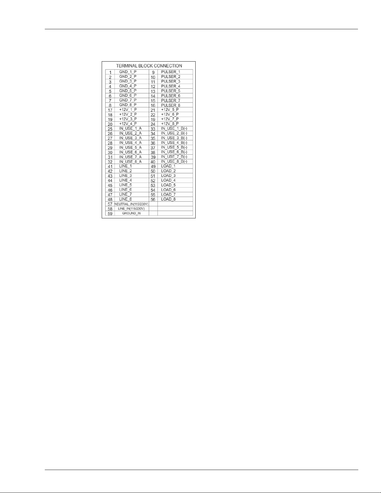
Figure 3-7: Terminal Block Connection
Installing FedEx Islander PLUS FMS
3 For pumps that are NOT Gasboy 9800’s, follow the wiring diagrams for electronic and
mechanical per your specific application.
MDE-5067 FedEx Islander PLUS FMS Installation Manual · March 2013 Page 3-9
Page 20
Installing FedEx Islander PLUS FMS
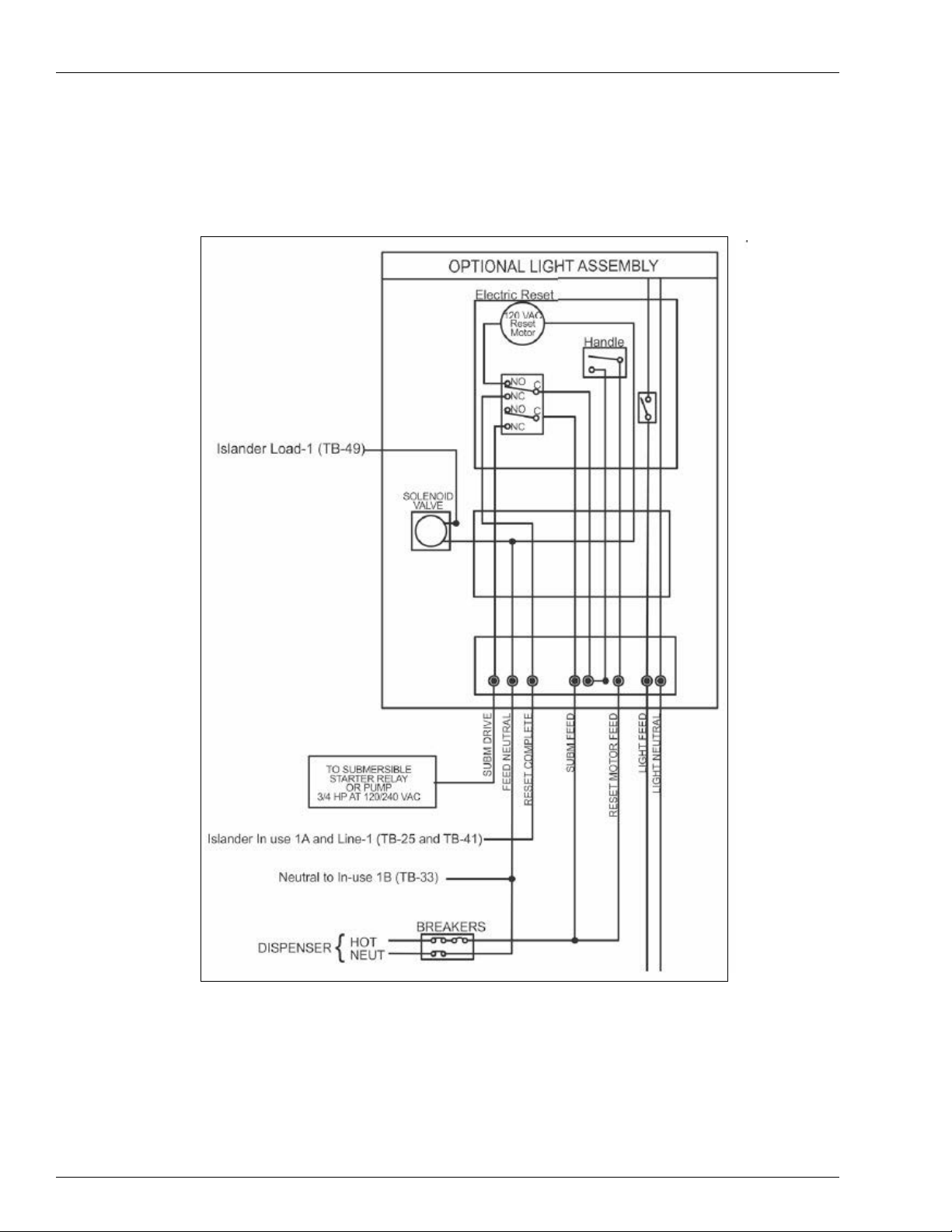
4 Mechanical dispenser: Note that instead of the solenoid lead tying to the Reset Complete wire;
it now connects directly to Terminal Block for the Gasboy PLUS. Also, note that the Reset
Motor and Submersible Feeds tie together in the junction box of the dispenser (see Figure 3-8).
Figure 3-8: Wiring Diagram - Mechanical Dispenser
Note: Reset Complete is the in-use line, this jumpers to line and the load line, which comes
back and run the solenoid valves. Pulse wires are polarized.
Page 3-10 MDE-5067 FedEx Islander PLUS FMS Installation Manual · March 2013
Page 21
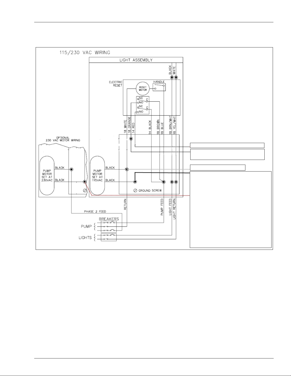
Figure 3-9: Mechanical Pump without Solenoid Valve
Disconnect from motor feed and cap wire.
Islander IN_Use_1A and Line (TB-25 and
TB-41)
Islander Load 1 (TB-49)
Pump Control Maximum Current
Pedestal with up to 4-hose mechanical pumps:
Motor Max: 1 HP @ 115 VAC
~OR~
2 HP @ 230 VAC
Additional relay must be used if pump motor
exceeds these limitations.
Pedestal with up to 8-hose mechanical pumps:
Motor Max: 3/4 HP @ 115 VAC
~OR~
1.5 HP @ 230 VAC
Additional external relay must be used if pump
motor exceeds these limitations.
Neutral to IN_Use 1B (TB-33)
Installing FedEx Islander PLUS FMS
MDE-5067 FedEx Islander PLUS FMS Installation Manual · March 2013 Page 3-11
Page 22
Installing FedEx Islander PLUS FMS
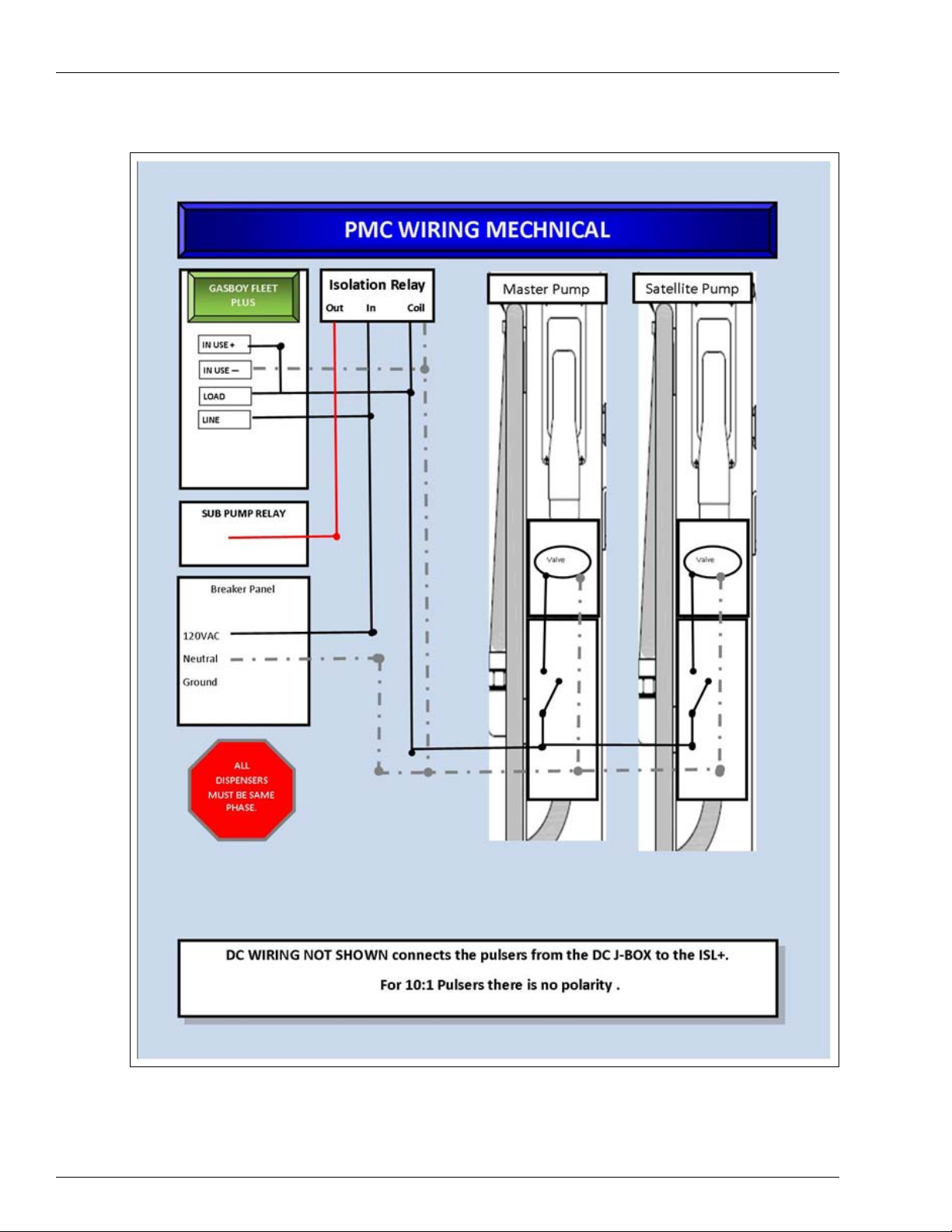
Figure 3-10: Mechanical Pumps On Stick - PMC Pumps
Page 3-12 MDE-5067 FedEx Islander PLUS FMS Installation Manual · March 2013
Page 23

Figure 3-11: Hose Reels Using 24 V Solenoids
Installing FedEx Islander PLUS FMS
MDE-5067 FedEx Islander PLUS FMS Installation Manual · March 2013 Page 3-13
Page 24

Installing FedEx Islander PLUS FMS
OrCU - Connect FedEx
WAN to LAN2
POE Adapter
Black Cable
“FedEx Islander PLUS FMS wireless networking equipment - DO NOT DISCARD”
This is a POE Adapter that FedEx Islander PLUS FMS uses for it wireless connections.
This will have a 12-24 V Power Adapter and an Ethernet connection. The black cable
shown in Figure 3-13 will commonly be found inside the existing FMS.
IMPORTANT INFORMATION
Connecting to FedEx Islander PLUS FMS Corporate Network
To connect to the FedEx Islander PLUS FMS corporate network, proceed as follows:
5 Locate the networking cable used in the existing FMS. Typical equipment is shown in
Figure 3-12 through Figure 3-14 on page 15. FedEx Islander PLUS FMS uses Power Over
Ethernet (POE) and fiber optics.
6 After you have located the WAN Cable, connect this to the LAN2 Port of the Orpak Controller
Unit (OrCU). The OrCU is located on the door of the 8-hose mechanical unit.
Figure 3-12: Connecting WAN Cable to LAN2 Port
Figure 3-13: POE
Page 3-14 MDE-5067 FedEx Islander PLUS FMS Installation Manual · March 2013
Page 25

Installing FedEx Islander PLUS FMS
(i)
(ii)
Termination Box
Switch
7 FedEx Islander PLUS FMS also uses fiber optic termination boxes and switches for
connecting to the corporate network. These devices are shown in Figure 3-14.
Figure 3-14: Fiber Optic Termination Box and Switch
MDE-5067 FedEx Islander PLUS FMS Installation Manual · March 2013 Page 3-15
Page 26

Installing FedEx Islander PLUS FMS
This page is intentionally left blank.
Page 3-16 MDE-5067 FedEx Islander PLUS FMS Installation Manual · March 2013
Page 27

Software Set Up SiteOmat Software Set Up
LAN1 - Configure
software using 5-port
switch.
4 – SiteOmat Software Set Up
Software Set Up
FedEx Islander PLUS FMS installation requires specific software to support T-Check Fleet
Cards. FedEx uses only T -Check Fleet Cards in its fueling operati ons to authorize transactions.
T-Check Fleet Cards are processed as any credit cards.
Process Check
Before you begin to configure software, verify that the correct software versions are loaded in
the SiteOmat.
To configure the SiteOmat software, proceed as follows:
1 Connect your laptop and Ethernet Cable to the LAN1 Port next to the 8-port CommVertor
Board (see Figure 4-1).
Figure 4-1: Configuring SiteOmat Software
MDE-5067 FedEx Islander PLUS FMS Installation Manual · March 2013 Page 4-1
Page 28

SiteOmat Software Set Up Software Set Up
2 Change the IP Address scheme on your laptop to align with the IP address scheme set in
OrCU. An IP 192.168.1.10 as your laptop IP will work (see Figure 4-2).
Figure 4-2: Setting IP Address
3 To log on to OrCU Administrator page, enter http://192.168.1.104:8090 in your browser. A
logon pop-up box appears.
4 Type the User name (as admin) and Password (as admin). See Figure 4-3.
Figure 4-3: Entering User Name and Password
5 Click OK.
Page 4-2 MDE-5067 FedEx Islander PLUS FMS Installation Manual · March 2013
Page 29

Software Set Up SiteOmat Software Set Up
The OrCU Administrator home page appears (see Figure 4-4).
Figure 4-4: OrCU Administrator Home Page
6 In the home page, verify that the correct OrCU FW and SiteOmat Versions appear.
• OrCU FW Version: 1.08 (SP8)
• SiteOmat Version: 6.4.33.098
7 Click MODIFIED (see Figure 4-4) to open the versions page. Verify the PAIS Version
[4.31.1.58 (see Figure 4-5)].
Figure 4-5: Verifying PAIS Version
MDE-5067 FedEx Islander PLUS FMS Installation Manual · March 2013 Page 4-3
Page 30

SiteOmat Software Set Up Software Set Up
OrCU Set Up
Before you begin verify you have SiteOmat WAN (LAN2) IP Address, Subnet Mask, and
Gateway IP Address. These are supplied on the FedEx Project Site Information Form.
To update the OrCU set up, proceed as follows:
1 Log into the OrCU Administration home page to see the IP, Net Mask, and MAC addresses of
both LAN ports. You will also notice the date and time of the system (see Figure 4-6).
2 Ensure that the softwares mentioned in step 6 on page 4-3 are installed before set up.
3 Click the Networking button (see Figure 4-6) to set the IP Address of LAN1 and LAN2. The
OrCU Networking screen appears as shown in Figure 4-6.
Figure 4-6: OrCU Networking Screen
Page 4-4 MDE-5067 FedEx Islander PLUS FMS Installation Manual · March 2013
Page 31

Software Set Up SiteOmat Software Set Up
4 Verify the LAN1 Network settings:
• IP: 192.168.1.104
• Mask: 255.255.0.0
• MAC: default setting (do not change)
Figure 4-7: V erifying LAN1 Network Settings
5 Set the LAN2 Network Settings according to the information supplied by FedEx in the FedEx
Project Site Information Form.
Column Name
Network Settings
IP OrCU Lan 2 IP Address
Mask OrCU Lan 2 Subnet Mask
MAC Default setting (do not change)
Gateway (GW)* OrCU Lan 2 GW (Gateway)
* Failure to set the gateway results in the
6 Set the Primary and Secondary Domain Name System [DNS (see Figure 4-7)], if provided.
Note: This is not currently used but may be implemented
7 Click the Save networking settings button, the notification text appears (see Figure 4-8).
Figure 4-8: Saving Networking Settings
(from where the data must be added)
inability t
o connect to the SiteOmat.
in the near future.
MDE-5067 FedEx Islander PLUS FMS Installation Manual · March 2013 Page 4-5
Page 32

SiteOmat Software Set Up Setting SiteOmat
Ensure all fueling activities are stopped at the island before applying the time settings.
IMPORTANT INFORMATION
8 Click the Apply Changes button to save the changes and power cycle the unit to activate the
new networking settings.
Figure 4-9: Applying Changes
9 Click the Time button to set the local Time, Date, and Time Zone information. The OrCU
Time Setup screen appears (see Figure 4-10).
Figure 4-10: Setting Time, Date, and Time Zone
10 In the OrCU Time Setup screen (see Figure 4-10), set the following:
• Time - Based on a 24-hour clock.
• Date - Format is DD/MM/YYYY.
• Time Zone - Set to Central for all sites.
11 Click the Change time settings button (see Figure 4-10).
12 On the System Information webpage, click the Reboot button to reboot OrCU.
~OR~
Power
cycle the SiteOmat.
Setting SiteOmat
To set the SiteOmat, proceed as follows:
1 Verify that the PC connection to the SiteOmat has the following:
• Operating System (OS) - Microsoft Windows
• Microsoft Internet Explorer 7 or later.
• Sun Microsystems Java
Note: Upgrade to the latest Java version if you experien
SiteOmat webpages (visit http://java.com).
™
application.
®
2000/XP®/2003/Win7.
ce any display issues with
Page 4-6 MDE-5067 FedEx Islander PLUS FMS Installation Manual · March 2013
Page 33

Setting SiteOmat SiteOmat Software Set Up
2 Enter https://192.168.1.104 in your browser to login to the SiteOmat webpage. The SiteOmat
Login screen appears (see Figure 4-11).
3 Type the User (as Admin) and Password (as Admin), and click Login (see Figure 4-11).
Figure 4-11: Entering Username and Password
The Pump Status screen of the SiteOmat appears.
• FedEx sites will have a default set up file loaded, there is no need t
• Default configuration - Status screen (see Figure 4-12).
- 4 - Mechanical pumps
irtual in use enabled - Nozzle points up
- V
- All pumps are blocked - Black pump head
Figure 4-12: Pump Statu s Screen
o run the wizard.
MDE-5067 FedEx Islander PLUS FMS Installation Manual · March 2013 Page 4-7
Page 34

SiteOmat Software Set Up Setting SiteOmat
4 Click the Setup button. The Setup screen appears (see Figure 4-13).
Figure 4-13: Setup Screen
5 Click the Advanced Mode button to continue (see Figure 4-14). The screen as shown in
Figure 4-15 appears.
Figure 4-14: Selecting Advanced Mode
Figure 4-15: Setup Screen
6 Click the Global tab to open the Station Parameters screen.
Page 4-8 MDE-5067 FedEx Islander PLUS FMS Installation Manual · March 2013
Page 35

Setting SiteOmat SiteOmat Software Set Up
The Global Station Parameters screen appears (see Figure 4-16).
Figure 4-16: Station Parameters Screen
MDE-5067 FedEx Islander PLUS FMS Installation Manual · March 2013 Page 4-9
Page 36

SiteOmat Software Set Up Setting SiteOmat
7 Set the following in the Station Parameters screen (see Figure 4-17):
• Description - Add the station description (stati
on name), which is available in the
SiteOmat Station Description column of the FedEx Project Site Information Form.
Note: Memphis as example: FXFMEM (FXF is FedEx Islander P
LUS FMS and MEM is
the location code).
• Code - Add the station code, which is available in the Sit
eOmat Station Code column of
the FedEx Project Site Information Form.
• City - Enter station city.
• Date format - Click the drop-down list from
Figure 4-17: Station Parameters Setting
Date format and select MM/DD/YYYY.
Page 4-10 MDE-5067 FedEx Islander PLUS FMS Installation Manual · March 2013
Page 37

Setting SiteOmat SiteOmat Software Set Up
8 In the General section (see Figure 4-18), enter the following:
• User Inactivity timeout - Set this to 60
seconds.
• Zero transactions - Select 5 from the drop-down list.
• Authorization Timeout - Set this to 60 seconds.
Figure 4-18: Global Parameters Section
9 Click the Save button to save the changes. A pop-up Processing box will display for few
seconds while saving (see Figure 4-19).
Figure 4-19: Global Parameter Processing
MDE-5067 FedEx Islander PLUS FMS Installation Manual · March 2013 Page 4-11
Page 38

SiteOmat Software Set Up Setting SiteOmat
10 In the Global screen, click the Advanced button.
Figure 4-20: Selecting Advanced Parameter
Page 4-12 MDE-5067 FedEx Islander PLUS FMS Installation Manual · March 2013
Page 39

Setting SiteOmat SiteOmat Software Set Up
The Advanced Station Parameters screen appears with the advanced options (see Figure 4-21).
Figure 4-21: Advanced Station Parameter
11 In the Formats section, set the Decimal point precision for volume to 2 (see Figure 4-21).
12 In the Payment Terminal section, click Setup. The Setup PAIS screen appears
(see Figure 4-22).
Figure 4-22: Setup PAIS Page
MDE-5067 FedEx Islander PLUS FMS Installation Manual · March 2013 Page 4-13
Page 40

SiteOmat Software Set Up Setting SiteOmat
Local Product Codes
set in the SiteOmat
13 Change the following on the Setup PAIS screen (see Figure 4-22 on page 4-13):
• Timeout - Set this to 45 seconds, this is
• Card may not be reused within - Set this to 0 mi
the time allowed to contact the host network.
nutes, which allows the same card to be
used again for oil or Diesel Exhaust Fluid (DEF) to be dispensed.
• Pre-authorize amount - Set this to $400.
• Credit processor - Select T-C
• Device Port - Enter the Device Port, which is available in the
heck from the drop-down list.
Fipay Port Number column
of the FedEx Project Site Information Form.
• Device IP - Enter the Device IP, which is available
in the Fipay Server IP Address column
of the FedEx Project Site Information Form.
14 Click the ProductMap button to map the local product codes that you have loaded into the
site to those which are predetermined by network processor. The Translate Product Codes
screen appears (see Figure 4-23).
Figure 4-23: Translate Product Codes
15 Verify that T-Check is available in Translation group drop-down list.
Page 4-14 MDE-5067 FedEx Islander PLUS FMS Installation Manual · March 2013
Page 41

Setting SiteOmat SiteOmat Software Set Up
16 Set the following in the Translate Product Codes screen based on the table:
• Product name - code: Select local product loaded in the Islander PLUS
system from the
Product name - code drop-down list.
• External code: Enter the correspon
ding network code for the local product set in the
Product name - code box.
External code Product name - code
62 DEF - 2000
63 Oil - 1
99 Diesel - 1200
Note: Repeat step 16 to add product codes.
17 After completing the entries, click OK to save (see Figure 4-23 on page 4-14); click Cancel to
exit the screen without saving.
18 Verify that the Daily run enabled check box is not selected (see Figure 4-22 on page 4-13).
19 Click the Save button (see Figure 4-21 on page 4-13) to save your changes and return to the
Station Parameters screen with the advanced options.
Figure 4-24: Setting Station Parameter
20 Click the Modify button to save the changes and return to the Global tab (see Figure 4-24).
21 From the Global tab (step 12 on page 4-13), click the Save button.
MDE-5067 FedEx Islander PLUS FMS Installation Manual · March 2013 Page 4-15
Page 42

SiteOmat Software Set Up Setting SiteOmat
(i)
(ii)
22 Click the Forecourt tab.
Figure 4-25: Selecting Forecourt
23 Before you continue, click the Save or Reload button to load the new configuration changes
into the system in the Forecourt tab.
Figure 4-26: Configuring Forecourt Tab
Clicking the Reload button displays a pop-up box as shown in Figure 4-27.
24 Click OK when reloading is complete.
Figure 4-27: Reloading SiteOmat Process
Page 4-16 MDE-5067 FedEx Islander PLUS FMS Installation Manual · March 2013
Page 43

Pump Configuration SiteOmat Software Set Up
Pump Configuration
To configure the pumps, proceed as follows:
1 To verify the pump configuration, click the Setup button from the status screen
(see Figure 4-28).
Figure 4-28: Verifying Pump Configuration
2 Click ... [ellipse (see Figure 4-28)]. The Setup Pump Settings screen appears.
Figure 4-29: Setup Pump Settings - General
3 In the General section, verify the following (see Figure 4-29):
• Pump Number - This is the number of the pump.
• Pump Head - For example, Pump Head is 1 for the first pump on th
e cluster and 2 for the
second pump on the cluster.
• Number of nozzles - For example, Number of nozzles will always be 1.
•
Mode - Select Need
Authorize from the drop-down list.
• Pump server - Select PumpServer from the drop-down list.
•
Cluster - Set 1 for the first two master pumps, 2 for the next two master pumps
.
MDE-5067 FedEx Islander PLUS FMS Installation Manual · March 2013 Page 4-17
Page 44

SiteOmat Software Set Up Pump Configuration
Following table shows the Cluster information for Mechanical Pumps.
Pump # Head Cluster
111
221
312
422
513
623
• Orpak Payment Terminal (OrPT) - Select ORPT from the drop-down list.
Note: This setting causes beeps at the isl
Figure 4-30: Verifying Pump Server - Message Factors
and when a ring or tag is read and authorized.
4 In the Message Factors section, verify that the details are set as shown in Figure 4-30.
• If transaction amount and volume are not being recorded properly this setting may need to
be
changed.
• Do not change until the Pulse Factor and DIP switches
Figure 4-31: Verifying Mechanical Pump - Card
have been verified and corrected.
Page 4-18 MDE-5067 FedEx Islander PLUS FMS Installation Manual · March 2013
Page 45

Pump Configuration SiteOmat Software Set Up
(i)
(ii)
The More Options button is not used for FedEx Islander PLUS FMS installations.
IMPORTANT INFORMATION
5 In the Specific section, verify the following is set up for the installed pumps
(see Figure 4-31 on page 4-18).
• Pulser Type - Select Half Cycle Count Pu
• Pulse Factor - Enter the correct setting for the inst
lse from the drop-down list.
alled pumps (as 10 or 100).
- 10 - 10:1 Pulser on PUMP
- 100 - 100:1 Pulser on PUMP
• Virtual In Use - Select Enable when a
handle switch is not available and select Disable at
all other times.
- This is always required for hose
- This is required for some dispensers (PMC Pu
reels for oil and lubricants.
mps) without proper handle-switch wires.
• Flow Protection timeout - Set this to 70 seconds.
Note: Flow protection timeout controls the active tim
e (70 seconds) of the Virtual In Use
after pulses stop.
6 Repeat steps 1 (on page 4-17) to 5 for all pumps and oil reels.
7 To save the pump configuration settings, click Save, the Setup screen appears.
Figure 4-32: Saving Pump Configuration
8 In the Setup screen, click Save (see Figure 4-32).
9 To load new configuration changes into the system, click Reload, a pop-up box appears as
shown in Figure 4-33 (i).
10 Click OK when reloading is complete [see Figure 4-33 (ii)].
Figure 4-33: Reloading Configuration
MDE-5067 FedEx Islander PLUS FMS Installation Manual · March 2013 Page 4-19
Page 46

SiteOmat Software Set Up Tank Configuration
Ta nk Configuration
To configure the tanks, proceed as follows:
1 To verify the tank configuration, from the status screen click the Setup button
(see Figure 4-34), the Setup screen appears.
Figure 4-34: Setup Screen
2 To view the additional options, click the Advanced Mode button.
Figure 4-35: Selecting Advanced Mode
Page 4-20 MDE-5067 FedEx Islander PLUS FMS Installation Manual · March 2013
Page 47

Tank Configuration SiteOmat Software Set Up
3 In the Setup screen, select the Forecourt > Tanks tab (see Figure 4-36). The Setup Tanks
screen appears (see Figure 4-37)
Figure 4-36: Setup Screen - Tanks Tab
Figure 4-37: Setup Tanks Screen
4
In the Setup Tanks screen, verify that the following Tanks are set up.
Capacity
Description Number
Tank_1 1 20000.00 Diesel
Tank_2 2 55.00 Oil
Tank_3 3 5000.00 DEF
MDE-5067 FedEx Islander PLUS FMS Installation Manual · March 2013 Page 4-21
(in Gallon) Fuel Type
Page 48

SiteOmat Software Set Up Tank Configuration
5 To verify that the products are set up, in the Tank Properties section, click the Products button
(see Figure 4-37 on page 4-21). The Setup Fuel Products screen appears (see Figure 4-38).
Figure 4-38: Setup Fuel Products Screen
6
Verify that the following Names (fuel types) are set up with the Codes.
Name Code
Oil 1
Diesel 1200
DEF 2000
Page 4-22 MDE-5067 FedEx Islander PLUS FMS Installation Manual · March 2013
Page 49

Setting Fuel Price SiteOmat Software Set Up
Setting Fuel Price
To set the fuel price, proceed as follows:
Pricing must be loaded for the pumps to properly op
erate. Use $1.00 for all products at this
time.
1 From the status screen, click the Wet Stock Mgmt button (see Figure 4-39), the Wet Price
screen appears (see Figure 4-40).
Figure 4-39: Selecting Wet Stock Management
2 From the Wet Price screen, click the Price Update tab. The available products screen appears
(see Figure 4-40).
Figure 4-40: Verifying Price Update
3 Click the name of the Product that you want to change (for example, change the price of
Diesel).
Figure 4-41: Modifying Price Update
4 Enter the updated price in the Price Update field (for example, $1.000).
5 Select the Update price now check box, click the Modify button to update the price.
MDE-5067 FedEx Islander PLUS FMS Installation Manual · March 2013 Page 4-23
Page 50

SiteOmat Software Set Up Unblocking or Activating Pumps
Pumps Status Screen
Pumps Setup Screen
(i)
(ii)
Unblocking or Activating Pumps
To unblock or activate pumps, proceed as follows:
After the SiteOmat is configured, unblock or activate the pumps/oil reel
s that are on the site.
All the pumps not being used will remain blocked.
1 Determine the pumps/reels that need to be activated and identify how they are numbered.
• For example, the island has tw
o master pumps with satellites and one oil reel.
• Master and satellites are numbered 1 and 2.
• Oil reel is numbered 4.
2 In this example, Pumps 1, 2, and 4 are active. Pump 3 is blocked.
• For example, Status screen [see Figure 4-42 (i)]
• For example, Setup screen [see Figure 4-42 (ii)]
Figure 4-42: Setup and Status Screen of Pump
3 On the Pump Status screen, right-click the pump that you want to unblock and select the
Unblock pump option from the list.
Note: Right-clicking at the black rectangle of the pump w
Figure 4-43: Unblocking Pump
Page 4-24 MDE-5067 FedEx Islander PLUS FMS Installation Manual · March 2013
orks best.
Page 51

Unblocking or Activating Pumps SiteOmat Software Set Up
If unsure which dispensers to unblock or which additional pumps to add, call Gasboy
Technical Support at 1-800-444-5529.
IMPORTANT INFORMATION
4 To activate the pump, in the Setup screen, select the Active check box for the pump that you
want to activate (see Figure 4-44).
Note: For example, only Pump 1 is active
Figure 4-44: Activating Pump
in the following screen.
MDE-5067 FedEx Islander PLUS FMS Installation Manual · March 2013 Page 4-25
Page 52

SiteOmat Software Set Up Weights & Measures (W&M) Dongle Activation Procedure
Mechanical pumps will not authorize if the W&M Dongle is NOT installed and set up.
IMPORTANT INFORMATION
Weights & Measures (W&M) Dongle Activation Procedure
To activate the W&M Dongle, proceed as follows:
1 Verify that the W&M Dongle is installed in OrCU.
Figure 4-45: W&M Dongle Installation
2 To log on to OrCU Administrator screen, enter https://192.168.1.104:8090 in your browser. A
logon pop-up box appears (see Figure 4-46).
Figure 4-46: OrCU Admin Login Dialog Box
Page 4-26 MDE-5067 FedEx Islander PLUS FMS Installation Manual · March 2013
Page 53

Weights & Measures (W&M) Dongle Activation Procedure SiteOmat Software Set Up
3 Enter User name (as admin) and Password (as admin).
4 Click OK. The OrCU Administrator home page appears (see Figure 4-47).
Figure 4-47: OrCU Administration Home Page
5 Click the Serial/Modem button (see Figure 4-48), the OrCU Serial/Modem setting screen
appears (see Figure 4-49 on page 4-28).
Figure 4-48: Serial/Modem Setup
MDE-5067 FedEx Islander PLUS FMS Installation Manual · March 2013 Page 4-27
Page 54

SiteOmat Software Set Up Weights & Measures (W&M) Dongle Activation Procedure
Figure 4-49: OrCU Serial/Modem Settings
6 In the OrCU Serial/Modem settings screen, perform the following:
• Select the Use port for External Devices (TLG) (Com2) button.
• Click the Set Serial/Modem s
After clicking the Set Serial/Modem settings
ettings button.
button, the following notification appears
(see Figure 4-50).
Figure 4-50: Serial/Modem Warning Screen
7 Power cycle Islander PLUS unit for the changes to take effect. Power cycle takes 2 to 3
minutes to complete.
Page 4-28 MDE-5067 FedEx Islander PLUS FMS Installation Manual · March 2013
Page 55

Weights & Measures (W&M) Dongle Activation Procedure SiteOmat Software Set Up
8 Verify that the W&M Dongle is activated. The pulse factor drop-down list will no longer be
present on the Setup screen.
Figure 4-51: Setting Pulse Factor
Process Check
After the wiring connections have been made, test the dispensers using the bypass switches on
the Terminal Block.
MDE-5067 FedEx Islander PLUS FMS Installation Manual · March 2013 Page 4-29
Page 56

SiteOmat Software Set Up Synchronizing with Fleet Head Office (FHO)
Synchronizing with Fleet Head Office (FHO)
Head Office Communicator (HOCOMM) user is added to communicate to the FHO. This user
is automatically added from the Setup screen.
HOCOMM User
To verify that the HOCOMM user is added to communicate to the FHO, proceed as follows:
1 From SiteOmat Status screen, click the Admin button. The Users SiteOmat screen appears
(see Figure 4-52).
Figure 4-52: SiteOmat Status Screen
2 Verify that the HOCOMM user is displayed in the list of users.
Page 4-30 MDE-5067 FedEx Islander PLUS FMS Installation Manual · March 2013
Page 57

Synchronizing with Fleet Head Office (FHO) SiteOmat Software Set Up
3 If the HOCOMM user does not exist, proceed to step 4 and add the HOCOMM user.
Figure 4-53: Adding HOCOMM User
4 Click the New button to add a user, the User properties screen appears (see Figure 4-54).
Figure 4-54: User Properties
5 Set the User Properties as follows (see Figure 4-54):
• Login name - Set the login name as HOCOMM (all capital letters).
• Password - Set the password as 123456.
• Confirm password - Enter the same password
• User is part of group - Select HO Com
6 Click the OK button to save the User Properties.
municator from the drop-down list.
(as 12345).
MDE-5067 FedEx Islander PLUS FMS Installation Manual · March 2013 Page 4-31
Page 58

SiteOmat Software Set Up Synchronizing with Fleet Head Office (FHO)
HOCOMM User Added
After saving the user properties, the newly added HOCOMM user displays in the list of users
(see Figure 4-55).
Figure 4-55: Verifying HOCOMM User
Synchronizing FedEx Islander PLUS FMS
To synchronize the FedEx Islander PLUS FMS, proceed as follows:
7 After completing hardware installation and software configuration, contact Travis Langston
(or delegated person) at 1-870-704-5230 to begin the syncing process.
8 Provide the FedEx Location Name information when calling for a download.
9 End User set up.
At this time… End Users will not have access to the FHO or SITE application. All
access will
be controlled specifically by the FedEx headquarters.
Page 4-32 MDE-5067 FedEx Islander PLUS FMS Installation Manual · March 2013
Page 59

Test Sequences SiteOmat Software Set Up
Test Sequences
After completing hardware installation and software configuration, test each pump and verify
transaction details.
Testing Procedure for Pumps
To test the pumps, proceed as follows:
1 Verify the fuel price has been downloaded to the SiteOmat from the FHO and is set to $1.000.
2 Ensure pumps are no longer in bypass mode.
3 Run a transaction using a T-Check Card. Record the transaction information and verify the
following:
• Transaction information is captured correctly in the S
• Quantity is recorded correctly and
• Correct pump numbers and nozzle numbers are dis
matches the pump.
iteOmat Status screen.
played in the SiteOmat Status screen.
Finalizing Installation
To ensure that the installation is complete, the Gasboy Fleet PLUS system must be online and
communicating with the FHO, and all the dispensers and satellites must be online and
operational.
Commission all serialized equipment (Islander
Installation Service Request with Gilbarco Claims. Have this information available before
communicating. You are also expected to commission and close the installation with Gilbarco
Claims before leaving the facility.
PLUS and FiPay Server) to close the
MDE-5067 FedEx Islander PLUS FMS Installation Manual · March 2013 Page 4-33
Page 60

SiteOmat Software Set Up Finalizing Installation
This page is intentionally left blank.
Page 4-34 MDE-5067 FedEx Islander PLUS FMS Installation Manual · March 2013
Page 61

Appendix A: Commissioning
*All installations for the FedEx Islander PLUS FMS require signed verification that the
installation is complete and the customer is satisfied. Per the ASC Notification Letter, no
payment will be remitted to the installer until required documentation is received.
AC Power confirmed to be within specification. T est at Idle. For more information, refer to “Pre-installation
Power Inspection” on page 3-1.
Neutral to Ground: measured at: ______________ (fill in value).
Hot to Ground: measured at: ______________ (fill in value).
Hot to Neutral: measured at: ______________ (fill in value).
AC Power confirmed to be within specification. Test at load (ALL PUMPS ON). For more information,
refer to “Pre-installation Power Inspection” on page 3-1.
Neutral to Ground: measured at: ______________ (fill in value).
Appendix A: Commissioning
Hot to Ground: measured at: ______________ (fill in value).
Hot to Neutral: measured at: ______________ (fill in value).
Fleet Manager trained in operation and manual bypass.
FiPay Server ground cable installed.
Program the SiteOmat.
Reboot SiteOmat.
Pumps and oil reels blocked and unblocked as needed.
Set up networking in the FiPay Server.
Set up T-Check information in the FiPay Server.
Perform all tests per the “Test Sequences” on page 4-33.
Commission equipment with Gilbarco claims via the Gilbarco extranet
(http://www.gilbarco.com/interactive/login.cfm), log into your account. If you do not currently have access
to the extranet, see your company gatekeeper for a username and password.
The Gasboy Fleet Plus system is operational and equipment has been commissioned with the
Gilbarco Claims Department.
Signature of Installer: _______________________________________________
ature of Fleet Manager/Director: ________________________________
Sign
Date: ___________________________
MDE-5067 FedEx Islander PLUS FMS Installation Manual · March 2013 Page A-1
Page 62

Appendix A: Commissioning
This page is intentionally left blank.
Page A-2 MDE-5067 FedEx Islander PLUS FMS Installation Manual · March 2013
Page 63

Installing Multiple Controller FedEx Islander PLUS FMS Appendix B: Multiple Controller Sites
(i) In the SiteOmat, if Pumps 2 and 4 are blocked, Pumps are wired at slots 1 and 3 in the Terminal Block.
(ii) In the SiteOmat, if Pumps 1 and 3 are blocked, Pumps are wired at slots 2 and 4 in the Terminal Block.
Oil Reel # 3
Pump # 1
Pump # 2
Oil Reel # 4
Appendix B: Multiple Controller Sites
Installing Multiple Controller FedEx Islander PLUS FMS
To keep pump numbering consistent with the existing scheme, extra pumps need to be added
to the system. Unused pumps will be blocked in the SiteOmat.
For example,
• A site has two Islander PLUS system
• There are two islands each with an Islander PLUS
• Pumps are numbered 1 - 2. Oil reels are numbered 3 - 4.
Figure B-1: Pump Statu s - SiteOmat and Terminal Block
s and two pumps and oil reels.
controlling, a pump and an oil reel.
MDE-5067 FedEx Islander PLUS FMS Installation Manual · March 2013 Page B-1
Page 64

Appendix B: Multiple Controller Sites Gasboy 9800 Series Pumps Business Inventory Reconciliation (BIR) Set Up
Gasboy 9800 Series Pumps Business Inventory Reconciliation (BIR) Set Up
Gasboy 9800 Series pumps need to be wired as mechanical pumps to maintain the BIR
interface to the tank gauge as shown in Figure B-2 and Figure B-3 on page B-3.
Figure B-2: Gasboy 9800 Series Pumps BIR Set Up - 1
Page B-2 MDE-5067 FedEx Islander PLUS FMS Installation Manual · March 2013
Page 65

Gasboy 9800 Series Pumps Business Inventory Reconciliation (BIR) Set Up Appendix B: Multiple Controller Sites
Figure B-3: Gasboy 9800 Series Pumps BIR Set Up - 2
MDE-5067 FedEx Islander PLUS FMS Installation Manual · March 2013 Page B-3
Page 66

Appendix B: Multiple Controller Sites Gasboy 9800 Series Pumps Business Inventory Reconciliation (BIR) Set Up
This page is intentionally left blank.
Page B-4 MDE-5067 FedEx Islander PLUS FMS Installation Manual · March 2013
Page 67

Appendix C: FedEx Project Site Information Form (Example Only)
FedEx Project Site Information Form
Following is the necessary information about the installation of 8 HOSE ISL+ w/FiPAY system for Federal Express Freight. You will be
provided a play book with all the necessary instruction that along with this information will allow you to successfully complete the
installation.
Take a few moments before you go to the site to read through this as well as the playbook. If you have any questions or concerns, do not
hesitate to call us so we can work through them before the day of installation.
GVR Site ID - 125644
Site Specific Information (You will need a separate one of these for each ISL + units).
OrCU Lan
2 IP
Address
OrCU Lan 2
Subnet
Mask
OrCU Lan
2 GW
(Gateway)
SiteOmat
Station
Description
SiteOmat
Station
Code
Fipay
ALPHA
Code
Fipay
Port
No.
Fipay
Server IP
Address
Fipay Server
Subnet Mask
Fipay
Server
Gateway
Fipay
Site
No.
xx.x.x.xx xxx.xxx.xxx.x xx.x.x.x xxxxxxx xxxxxx xxx xxxxx xx.x.x.xx xxx.xxx.xxx.x xx.x.x.x xxxxx
Note: This table is ONLY a sample.
Tasks to Perform While On-site
Inspect site for any obvious problems with Wiring, Hoses, Nozzles and so on. Alert Project Manager immediately in the event
issues are found you feel will not allow you to complete the project at this time.
Verify proper operation of existing equipment.
Verify E-Stop is working properly.
Verify you have all required Equipment/Tools/Supplies/Personnel to complete the work before you begin.
De-energize all power to existing island card reader and remove existing FMS system.
Clearly mark all wiring to existing system.
Install new ISL+ unit and wire.
Install FiPAY server retrofit kit into ISL+ unit.
Power up unit and program unit as per Playbook.
Verify proper operation.
Train on-site personnel on proper operation.
Important Contact Information
Gilbarco/Gasboy FedEx Freight Corporate Offices
Bob Griffith - 1.336.547.5654
Gasboy TAC - 1.800.444.5529
Travis Langston - 1.870.704.5230
Justin Hudson - 1.870.416.6482
Appendix C: FedEx Project Site Information Form
(Example Only)
MDE-5067 FedEx Islander PLUS FMS Installation Manual · March 2013 Page C-1
Page 68

Appendix C: FedEx Project Site Information Form (Example Only)
This page is intentionally left blank.
Page C-2 MDE-5067 FedEx Islander PLUS FMS Installation Manual · March 2013
Page 69

Index
Index
A
A
Admin 7
Advanced Mode 8
Alert symbol 1
Authorization Timeout 11
B
Barricading 1
Black pump head 7
Board Support Package 1
BSP 2
Bypass Switches 29
C
Caution warnings 1
Cluster 17
Com2 28
Corporate Network 14
Credit card 1
Credit processor 14
D
Danger warnings 1
DEF 14
Device IP 14
Device Port 14
DNS 2
E
Electrical
Shut-off 1
Electronic 9
Emergency
Electrical shut-off 1
In Case Of 3
Personnel (contacting) 2
Evacuation 1
Explosions
Preventing 1
F
FedEx 5
FedEx Islander PLUS FMS 1
FedEx Project Site Information
Form 1
FHO 2
Fiber Optic 15
FiPay Server 33
Fires
Preventing 1
FMS 2
Forecourt 16
Fuel Management System 1
Fueling Site Safety 3
G
Gasboy 9
Gasboy Technical Support 25
Gilbarco Claims 1
Global Station Parameters 9
GW 2
H
Half Cycle Count Pulse 19
HOCOMM 2
Hose Reels 13
J
Junction box 10
L
LAN 2
LAN1 1
LAN2 4
M
MAC addresses 4
Mechanical 9
Memphis 10
Message Factors 18
N
Nozzle 7
O
Operations Manager 1
OrCU 2
OrCU Administrator 2
OrCU FW Version 3
OrCU Networking 4
OrPT 2
OS 6
P
PAIS 2
PAIS version 3
Payment Application Interface
Service 1
Personnel
Emergency (informing) 2
PMC Pumps 12
POE 2
Power adaptor 14
Power cycle 28
Power Over Ethernet 14
Process Check 29
ProductMap 14
Pulse Factor 18
Pulse wires 10
Pump Head 17
Pump Number 17
Pump server 17
R
Reset Complete 10
Reset Motor 10
S
Safety Information 1
Alert symbol 1
Barricading 1
Emergency electrical shut-off
1
MDE-5067 FedEx Islander PLUS FMS Installation Manual · March 2013 Index-1
Page 70

Index
Emergency personnel 2
Evacuation 1
NFPA regulations 1
Open flames 2
Preventing explosions and
fires 1
Regulations 1
Replacement parts 1
Safety symbols 1
Shut-off 1
Signal words 1
Smoking 2
Sparks 2
Warning words 1
Working alone 2
Safety symbols 1
Serial/Modem setting 27
Setup Pump Setting 17
Shut-off 1
Emergency electrical 1
Signal words
Safety 1
Site Number 3
SiteOmat 1
SiteOmat Status 33
SiteOmat Version 3
Solenoid lead 10
Solenoid valves 10
Specific 19
STP 2
Subnet Mask 3
Synchronizing 32
V
Version 1
W
W&M dongle 26
WAN 2
Warning words 1
Warnings 1
Wet Stock Management 23
Z
Zero transactions 11
T
Tank configuration 20
Tank gauge 2
T-Check 14
T-Check Fleet cards 1
Terminal Block 8
Terminal Block Connection 9
Time Zone 6
Translation group 14
U
User Inactivity timeout 11
User properties 31
Index-2 MDE-5067 FedEx Islander PLUS FMS Installation Manual · March 2013
Page 71

This page is intentionally left blank.
Index
MDE-5067 FedEx Islander PLUS FMS Installation Manual · March 2013 Index-3
Page 72

Gilbarco® is a registered trademark of Gilbarco Inc. Internet Explorer®, Windows®, and XP® are registered trademarks of Microsoft
™
Corporation. Java
is a trademark of Sun Microsystems, Inc.
© 2013 GASBOY
7300 West Friendly Avenue · Post Office Box 22087
Greensboro, North Carolina 27420
Phone 1-800-444-5529 · http://www.gasboy.com · Printed in the U.S.A.
MDE-5067 FedEx Islander PLUS FMS Installation Manual · March 2013
 Loading...