

Page 1
Installation Procedure for the Verifone Pin Pad to CFN3
Hardware/Software covered by this procedure:
These instructions detail installation of the Verifone Pin Pad option in a CFN3 with an integral Profit Point configuration. If you do not have a CFN3 or if you are not sure, DO NOT proceed. Contact your service representative or Gasboy to verify the type of system you have.
Pin Pad Kit for CFN3, part number C07505.
Items needed for installation
• C01626 Pin Pad - Verifone
• C06242 Cable Assy, 4-pos, 1:1 phone
• C07509 PC Expansion Port Comm. PCB
• C05991 Cable Assy., DB9F - to DB9F, 1:1
• C09543 Decal, “SER3/SER4/LPTs” BLK-CLR
Installation instructions
Static electricity can damage computer components and your Communication PCB. We recommend keeping your
Comm. PCB in its protective bag until you are ready to install it. We also recommend you observe antistatic precautions when handling the PC and/or Comm. PCB.
1. Turn off power to the PC and disconnect the cables from the back of the PC.
2. Remove the cover from the PC.
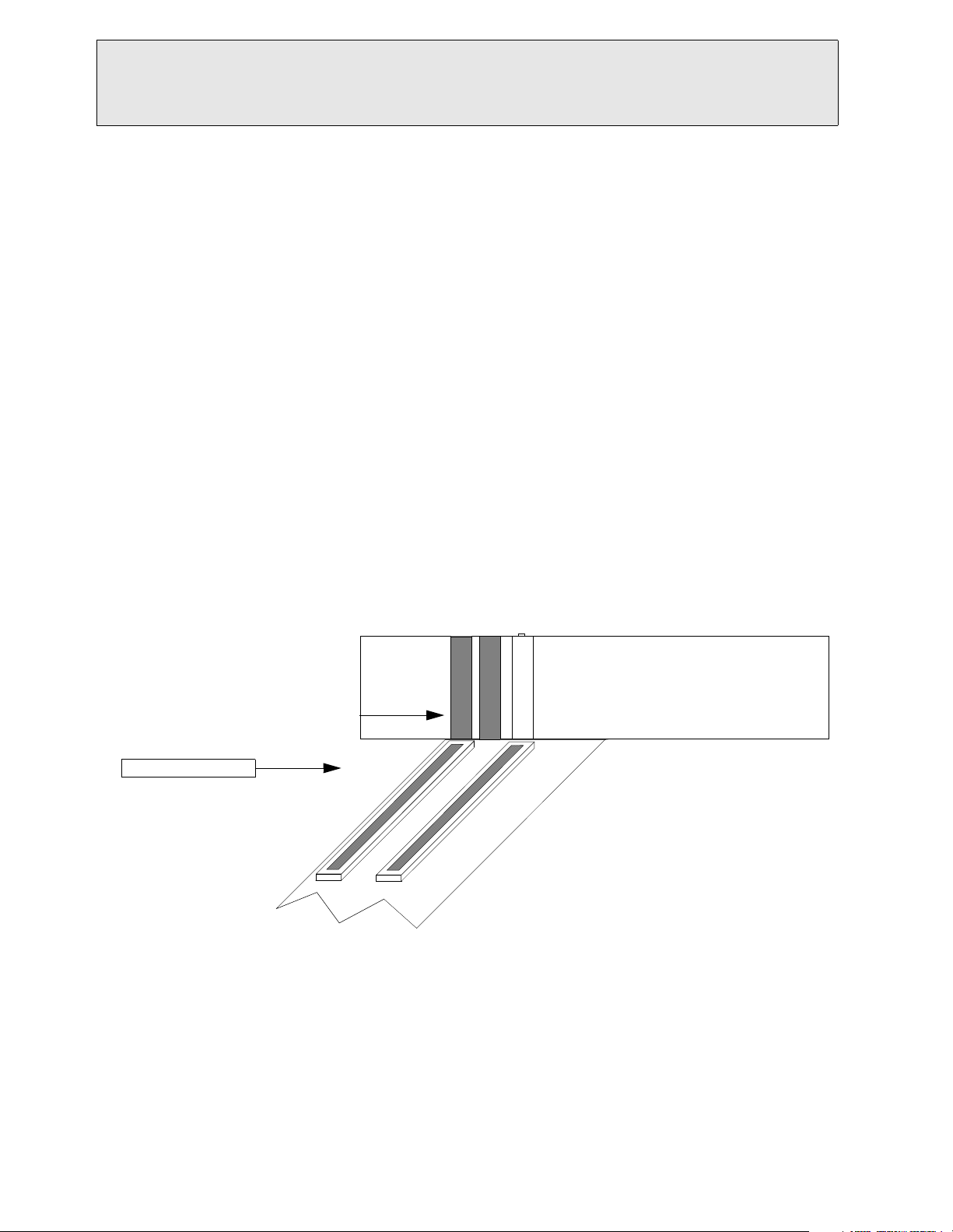
3. On the PC motherboard are several PCI expansion slots. Find an unused PCI slot and remove the slot covers next
to it. You will need two.
Slots on back
Covers removed
PCI expansion slot
Motherboard
4. Attach the ribbon cable and bracket assembly to the Comm. PCB. Be sure to align pin one of the cable (indicated
by a colored stripe on the cable [often red]) with pin one of the PCB connector. Refer to installation guide
included with the Comm. PCB. Insert the Comm PCB into the unused PCI slot so that the connectors on the PCB
protrude through the expansion slot.
of PC
PC is lying on side
5. Install the metal bracket assembly (attached to the ribbon cable) into the upper expansion slot. Install the expansion cover retainer and screw in, using screw that was removed (Step 3).
C35925 Page 1 version 1.3 - 12/11/00
Page 2
Installation Procedure for the Verifone Pin Pad to CFN3
6. Reassemble the CFN3 PC by replacing the cover. Be careful not to pinch any wires or cables. Install the decal to
the back of the expansion slots.
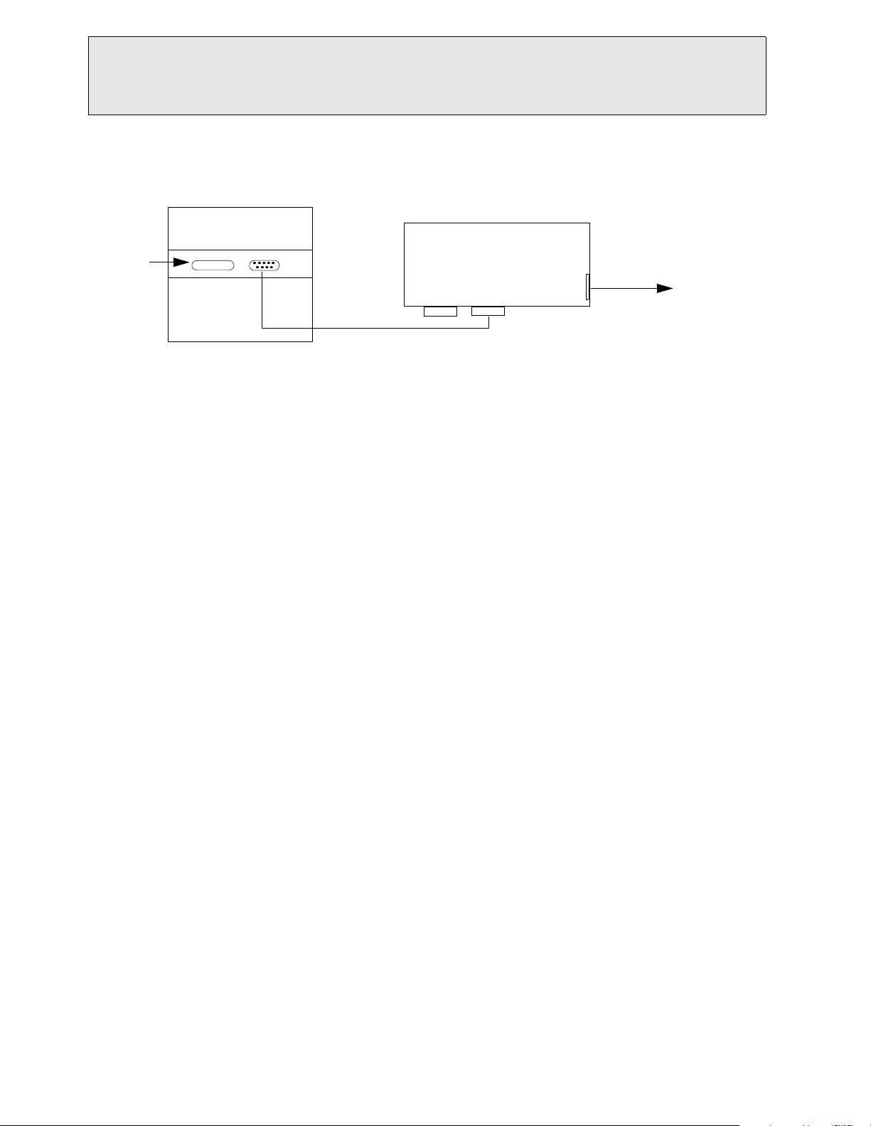
7. Attach all cables to their previous connection on the back of the PC. Connect one end of the C05991 cable to
SERIAL 3 port. Connect the other end to the POS distribution box SERIAL 3 port.
Bracket
Assembly
Serial 3
Gasboy
Distribution Box
Serial 2 Serial 3
Back of PC
C05991 cable
Power
Pin Pad
C06242 phone cable
To P I N
PA D
8. Attach one end of the 4-position phone cable (C06242) into the POS distribution box PIN PAD port and the other
end into the Pin pad.
9. Once installation is complete, power up the CFN3 PC. Verify the Verifone Pin Pad and CFN3 are configured correctly. See the Profit Point Reference Manual, C35746 Hardware Configuration to see if the Profit Point is configured correctly. See the CFN3 Configuration Manual, C09326 Console Configuration to see if the Site
Controller is configured correctly.
10. If the CFN3 and Profit Point are configured correctly and the Pin Pad is operational, you do not have to go any
further and can stop here. However, if the Pin Pad is not working once the system is loaded, you may need to
load a driver for your new Comm. PCB. Follow the instructions supplied with the Comm. PCB for loading drivers for Windows NT v4.0.
C35925 Page 2 version 1.3 - 12/11/00
 Loading...