

Page 1

Introduction
This document provides instructions for installing the NPT Discharge Kit (M06648K001) on
™
units.
Atlas
Intended Users
The intended users of this document are Authorized Service Contractors (ASCs), Software
Quality Assurance (SQA) and Manufacturing personnel.
Abbreviations and Acronyms
The following table contains a list of acronyms used in this document.
MDE-4533
Instructions for Installing Atlas™ NPT
Discharge Kit (M06648K001)
December 2005
Term Expansion
ASC Authorized Service Contractor
SQA Software Quality Assurance
Warranty
For information on warranty, refer to Gasboy’s Warranty Policy Statement - MDE-4255. If
you have any warranty-related questions, contact Gasboy’s Warranty Department at its
Greensboro location.
Required Tools
• 13 mm socket and ratchet
• Pipe wrench
• Channel-lock pliers (2 sets or other means of tightening 2 fittings, for example vise)
MDE-4533 Instructions for Installing Atlas™ NPT Discharge Kit (M06648K001) • December 2005 Page 1
Page 2
Introduction
Parts List
Discharge kit (M06648)
The M06648K001 kit contains the following parts:
Description Part Number Quantity
1-inch Std. Pipe X 6.88 R11495-123 1
Fitting, Discharge Meter Hose M04624B020 1
O-ring .862 X .103 N16891-32 1
Bracket, Discharge Mount Discharge
Kit
Screw Metric M8 X 25 M00415B011 2
Plate, Discharge Blanking M06432A002 1
Nut, Metric, Hex Serrd Flanged (M8) M00414B003 6
U-Bolt Metric M00703B001 1
Grommet, Discharge 1-inch Pipe 028960 1
Elbow 1-inch X 90 Degree Painted 024895 1
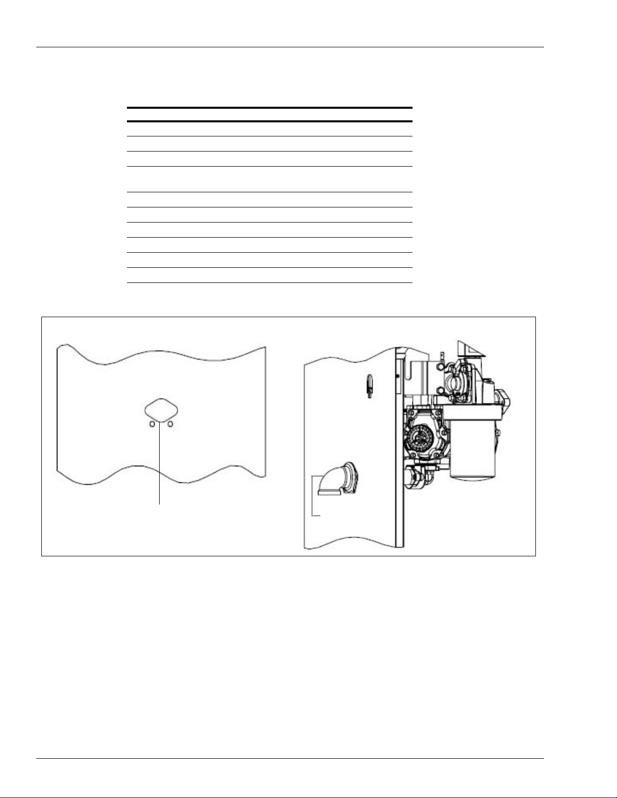
Figure 1: Discharge Kit
M06642B001 1
Assembled View of Discharge Kit
Discharge hole in sheathing
Elbow
Note: This kit is for Atlas units with the sheathing configuration shown above.
Page 2 MDE-4533 Instructions for Installing Atlas™ NPT Discharge Kit (M06648K001) • December 2005
Page 3
Important Safety Information
Important Safety Information
This section introduces the hazards and safety precautions
associated with installing, inspecting, maintaining or servicing
this product. Before performing any task on this product, read
this safety information and the applicable sections in this
manual, where additional hazards and safety precautions for
your task will be found. Fire, explosion, electrical shock or
pressure release could occur and cause death or serious
injury, if these safe service procedures are not followed.
Preliminary Precautions
You are working in a potentially dangerous environment of
flammable fuels, vapors, and high voltage or pressures. Only
trained or authorized individuals knowledgeable in the related
procedures should install, inspect, maintain or service this
equipment.
Emergency Total Electrical Shut-Off
The first and most important information you must know is
how to stop all fuel flow to the pump/dispenser and island.
Locate the switch or circuit breakers that shut off all power to
all fueling equipment, dispensing devices, and Submerged
Turbine Pumps (STPs).
!
WARNING
!
The EMERGENCY STOP, ALL STOP, and
PUMP STOP buttons at the cashier’s station
WILL NOT shut off electrical power to the pump/
dispenser. This means that even if you activate
these stops, fuel may continue to flow
uncontrolled.
Read the Manual
Read, understand and follow this manual and any other
labels or related materials supplied with this equipment. If you
do not understand a procedure, call a Gasboy Authorized
Service Contractor or call the Gasboy Support Center at 1800-800-7498. It is imperative to your safety and the safety of
others to understand the procedures before beginning work.
Follow the Regulations
Applicable information is available in National Fire Protection
Association (NFPA) 30A; Code for Motor Fuel Dispensing
Facilities and Repair Garages, NFPA 70; National Electrical
Code (NEC), Occupational Safety and Hazard Association
(OSHA) regulations and federal, state, and local codes. All
these regulations must be followed. Failure to install, inspect,
maintain or service this equipment in accordance with these
codes, regulations and standards may lead to legal citations
with penalties or affect the safe use and operation of the
equipment.
Replacement Parts
Use only genuine Gasboy replacement parts and retrofit kits
on your pump/dispenser. Using parts other than genuine
Gasboy replacement parts could create a safety hazard and
violate local regulations.
Safety Symbols and Warning Words
This section provides important information about warning
symbols and boxes.
Alert Symbol
You must use the TOTAL ELECTRICAL SHUTOFF in the case of an emergency and not the
console’s ALL STOP and PUMP STOP or
similar keys.
Total Electrical Shut-Off Before Access
Any procedure that requires access to electrical components
or the electronics of the dispenser requires total electrical
shut off of that unit. Understand the function and location of
this switch or circuit breaker before inspecting, installing,
maintaining, or servicing Gasboy equipment.
Evacuating, Barricading and Shutting Off
Any procedure that requires access to the pump/dispenser or
STPs requires the following actions:
• An evacuation of all unauthorized persons and vehicles
from the work area
• Use of safety tape, cones or barricades at the affected
unit (s)
• A total electrical shut-off of the affected unit (s)
This safety alert symbol is used in this manual and
on warning labels to alert you to a precaution which must be
followed to prevent potential personal safety hazards. Obey
safety directives that follow this symbol to avoid possible
injury or death.
Signal Words
These signal words used in this manual and on warning
labels tell you the seriousness of particular safety hazards.
The precautions below must be followed to prevent death,
injury or damage to the equipment:
DANGER: Alerts you to a hazard or unsafe practice
!
which will result in death or serious injury.
WARNING: Alerts you to a hazard or unsafe
!
practice that could result in death or serious injury.
CAUTION with Alert symbol: Designates a hazard
!
or unsafe practice which may result in minor injury.
CAUTION without Alert symbol: Designates a
hazard or unsafe practice which may result in
property or equipment damage
Working With Fuels and Electrical Energy
Prevent Explosions and Fires
Fuels and their vapors will explode or burn, if ignited. Spilled
or leaking fuels cause vapors. Even filling customer tanks will
cause potentially dangerous vapors in the vicinity of the
dispenser or island.
MDE- 4533 Instructions for Installing Atlas NPT Discharge Kit (M06648K001) • December 2005 Page 3
Page 4

Important Safety Information
No Open Fire
Open flames from matches, lighters, welding
torches or other sources can ignite fuels and their vapors.
No Sparks - No Smoking
Sparks from starting vehicles, starting or using power tools,
burning cigarettes, cigars or pipes can also ignite fuels and
their vapors. Static electricity, including an electrostatic
charge on your body, can cause a spark sufficient to ignite
fuel vapors. Every time you get out of a vehicle, touch the
metal of your vehicle, to discharge any electrostatic charge
before you approach the dispenser island.
Working Alone
It is highly recommended that someone who is capable of
rendering first aid be present during servicing. Familiarize
yourself with Cardiopulmonary Resuscitation (CPR) methods,
if you work with or around high voltages. This information is
available from the American Red Cross. Always advise the
station personnel about where you will be working, and
caution them not to activate power while you are working on
the equipment. Use the OSHA Lockout/ Tagout procedures. If
you are not familiar with this requirement, refer to this
information in the service manual and OSHA documentation.
Working With Electricity Safely
Ensure that you use safe and established practices in
working with electrical devices. Poorly wired devices may
cause a fire, explosion or electrical shock. Ensure that
grounding connections are properly made. Take care that
sealing devices and compounds are in place. Ensure that you
do not to pinch wires when replacing covers. Follow OSHA
Lockout/Tagout requirements. Station employees and service
contractors need to understand and comply with this program
completely to ensure safety while the equipment is down.
In an Emergency
Inform Emergency Personnel
Compile the following information and inform emergency
personnel:
• Location of accident (for example, address, front/back of
building, and so on)
• Nature of accident (for example, possible heart attack, run
over by car, burns, and so on)
• Age of victim (for example, baby, teenager, middle-age,
elderly)
• Whether or not victim has received first aid (for example,
stopped bleeding by pressure, and so on)
• Whether or not a victim has vomited (for example, if
swallowed or inhaled something, and so on)
WARNING
!
Gasoline ingested may cause unconsciousness
and burns to internal organs.
Do not induce vomiting.
Keep airway open.
Oxygen may be needed at scene.
Seek medical advice immediately.
WARNING
!
Gasoline inhaled may cause unconsciousness
and burns to lips, mouth and lungs.
Keep airway open.
Seek medical advice immediately.
WARNING
!
Gasoline spilled in eyes may cause burns to eye
tissue.
Irrigate eyes with water for approximately 15
minutes.
Seek medical advice immediately.
WARNING
Hazardous Materials
Some materials present inside electronic enclosures may
present a health hazard if not handled correctly. Ensure that
you clean hands after handling equipment. Do not place any
!
Gasoline spilled on skin may cause burns.
Wash area thoroughly with clear water.
Seek medical advice immediately.
equipment in the mouth.
!
WARNING
The pump/dispenser contains a chemical known to the
State of California to cause cancer.
IMPORTANT: Oxygen may be needed at scene if gasoline
has been ingested or inhaled. Seek medical advice
immediately.
Lockout/Tagout
Lockout/Tagout covers servicing and maintenance of
WARNING
!
machines and equipment in which the unexpected
energization or start-up of the machine(s) or equipment or
The pump/dispenser contains a chemical known to the
State of California to cause birth defects or other
reproductive harm.
release of stored energy could cause injury to employees or
personnel. Lockout/Tagout applies to all mechanical,
hydraulic, chemical or other energy, but does not cover
electrical hazards. Subpart S of 29 CFR Part 1910 - Electrical
Hazards, 29 CFR Part 1910.333 contains specific Lockout/
Tagout provision for electrical hazards.
Page 4 MDE- 4533 Instructions for Installing Atlas NPT Discharge Kit (M06648K001) • December 2005
Page 5

Hazards and Actions
Important Safety Information
!
WARNING
Spilled fuels, accidents involving pumps/dispensers, or uncontrolled fuel flow create a
serious hazard.
Fire or explosion may result, causing serious injury or death.
Follow established emergency procedures.
The following actions are recommended regarding these hazards:
Collision of a Vehicle with Unit Fire at Island Fuel Spill
• Do not go near a fuel spill or allow anyone else in the area.
• Use station EMERGENCY CUTOFF immediately. Turn off all system circuit breakers to the island(s).
• Do not use console E-STOP, ALL STOP and PUMP STOP to shut off power. These keys do not
remove AC power and do not always stop product flow.
• Take precautions to avoid igniting fuel. Do not allow starting of vehicles in the area. Do not allow
open flames, smoking or power tools in the area.
• Do not expose yourself to hazardous conditions such as fire, spilled fuel or exposed wiring.
• Call emergency numbers.
Page 5 MDE- 4533 Instructions for Installing Atlas NPT Discharge Kit (M06648K001) • December 2005
Page 6

This page is intentionally left blank.
Important Safety Information
Page 6 MDE- 4533 Instructions for Installing Atlas NPT Discharge Kit (M06648K001) • December 2005
Page 7

Installing Atlas NPT Discharge Kit (M06648K001)
Installing Atlas NPT Discharge Kit (M06648K001)
To install the Atlas Discharge Kit, proceed as follows:
1 Remove the existing discharge fitting from the exterior of the unit, copper discharge tube and
meter discharge fitting.
Figure 2: Discharge Kit Assembly
Serrated Hex nut
Mounting
bracket
90 Degree
painted elbow
Discharge
pipe grommet
2 Apply pipe sealant to the threads of the 1-inch pipe nipple (R11495-123).
Note: Use sealant approved for use with petroleum products.
3 Insert the nipple into the discharge fitting (M04624B020) and tighten it.
Note: Ensure that you do not overtighten the nipple.
Blanking
plate
Sheathing 1-inch Std.
U-bolt
pipe
Discharge
meter hose
fitting
O-ring
4 Apply oil to the O-ring (N16891-32) and insert it into the O-ring groove in the meter
discharge.
Note: Ensure that the O-ring is properly aligned with the grooves while inserting.
MDE- 4533 Instructions for Installing Atlas NPT Discharge Kit (M06648K001) • December 2005 Page 7
Page 8

Installing Atlas NPT Discharge Kit (M06648K001)
5 Slide the discharge mounting bracket (M06642B001) over the nipple.
6 Inserting the open nipple end through the discharge hole in the frame, insert the discharge
fitting (M04624B020) into the meter discharge and place and tighten the (2) screws
(M00415B011).
7 Slide the discharge blanking plate (M06432A002) over the nipple protruding on the outside of
the unit so that the attached clinch-studs are inserted through the frame.
8 Slide the discharge mounting bracket (M06642B001) to the frame capturing the clinch studs
on the blanking plate through the holes in the discharge mounting bracket. Place (4) M8
flanged nuts (M00414B003) to the studs and tighten.
9 Slide the U-bolt (M00703B001) through the holes on top of the discharge mounting bracket so
that it captures the nipple. Place (2) M8 flanged nuts (M00414B003) to the U-bolt and tighten
them.
10 Slide the discharge grommet (028960) over the end of the nipple to where the rear face of the
grommet is against the blanking plate.
11 Apply pipe sealant to the threads of the 1-inch painted elbow (024895), screw it onto the
nipple and tighten the elbow.
Note: While tightening the elbow, use a cloth to wrap the elbow or some other means of
protecting the elbow’s finish.
12 Reattach hoses and hardware. After purging air from unit, check for leaks.
© 2005 GASBOY
7300 West Friendly Avenue • Post Office Box 22087
Greensboro, North Carolina 27420
Phone 1-800-444-5529 • http://www.gasboy.com • Printed in the U.S.A.
MDE- 4533 Instructions for Installing Atlas NPT Discharge Kit (M06648K001) • December 2005
 Loading...