

Page 1

Atlas™ Fuel Systems
Owner’s Manual
MDE-4363A
Page 2

Computer Programs and Documentation
Gasboy , Gr eensbor o, is an ISO 900 1:20 00 regi stered facil ity.
U
U
M
M
M
M
:
N
A
C
I
FCC Warning
All Gasboy computer programs (including software on diskettes and within memory chips) and documentation are copyrighted by, and shall remain the property of, Gasboy. Such
computer programs and documents may also contain trade secret information. The duplication, disclosure, modification, or unauthorized use of computer programs or
documentation is strictly prohibited, unless otherwise licensed by Gasboy.
This equipment has been tested and found to comply with the limits for a Class A digital device pursuant to Part 15 of the FCC Rules. These limits a r e designed to provide
reasonable protection against harmful interference when the equipment is operated in a commercial environment. This equipment generates, uses, and can radiate radio frequency
energy, and if not installed and used in accordance with the instruction manual, may cause harmful interference to radio communic ations. Operation of this equipment in a
residential area is likely to cause harmful interference in which case the user will be required to correct the interference at his own expense. Changes or modifications not expressly
approved by the manufacturer could void the user’s authority to operate this equipment.
Approvals
nderwriters Laboratories:
. L. File# Products listed with U. L.
H4314
H6418
H7404
H10581 Key con t ro l u n it , Mo d e l G K E- B S e ri es
All dispensers and self-contained pumping
units
Power operated Transfer Pump Models 25,
25C, 26, 27, 28, 72, 72S, 72SP, 72X, 73 and
1820
Hand operated Transfer Pump Models 1230
Series, 1243 Series, 1520 and 1720 Series
Card reader terminals, Models 1000, 1000P
Site controller, Model 2000S CFN Series
Data entry terminals, Model TPK-900 Series
Fuel Point Reader System
New York City:
NYFD C of A # Product
4823 9100A, 9140A, 9152A, 9153A,
4997 9822A, 9823A
5046 9100Q, 9140Q, 9152Q, 9153Q,
9800A, 9840A, 9850A, 9852A,
9853A, 9140
9800Q, 9840Q, 9852Q, 9853Q
California Air Resources Board (CARB)
Executive Order # Product
G-70-52-AM Balance Vapor Recovery
G-70-150-AE VaporVac
NCWM - Certificate of Compliance:
Gasboy pumps and dispensers are evaluated by the National Confer ence of Weights and Measures (NCWM) under the National Type Evaluation Program (NTEP).
NCWM has issued the following Certificates of Compliance (COC):
COC# Product Model # COC# Product Model # COC# Product Model #
95-179A2 Dispenser
95-136A5 Dispenser 9800 Series 91-057A3 Controller
Patents
Gasboy products are manufactured or sold under one or more of the following U.S. patents.:
9100 Retail Series, 8700
Series, 9700 Series
91-019A2 Dispenser
9100 Commercial
Series
1000 Series FMS,
2000S-CFN Series
Dispensers
5,257,720
Point of Sale/Back Office Equipment
D335,673
Trademarks
on-registered trademarks
tlas™
onsola™
nfinity™
This document is subject to change without notice. · For information regarding Gasboy Literature, call (336) 547-5661
E-mail: literature@gasboy.com · Internet: http://www.gasboy.com
2005 GASBOY · All Rights Reserved
Registered trademarks
®
ASTRA
®
Fuel Point
®
Gasboy
®
Keytrol
®
Slimline
Additional U.S. and foreign trademarks
pending.
Other brand or product names shown may be
trademarks or registered trademarks of their
respective holders.
Additional U.S. and foreign patents pending.
Page 3

Table of Contents
Table of Contents
Important Safety Information 3
In An Emergency . . . . . . . . . . . . . . . . . . . . . . . . . . . . . . . . . . . . . . . . . . . . 5
Introduction 6
Intended User. . . . . . . . . . . . . . . . . . . . . . . . . . . . . . . . . . . . . . . . . . . . . . . 6
Scope. . . . . . . . . . . . . . . . . . . . . . . . . . . . . . . . . . . . . . . . . . . . . . . . . . . . . 6
Acronym Table. . . . . . . . . . . . . . . . . . . . . . . . . . . . . . . . . . . . . . . . . . . . . . 6
Pump/Dispenser Components 7
Atlas Pump/Dispenser . . . . . . . . . . . . . . . . . . . . . . . . . . . . . . . . . . . . . . . . 7
Common Functions 9
Understanding Date Codes . . . . . . . . . . . . . . . . . . . . . . . . . . . . . . . . . . . . 9
Pump Totals. . . . . . . . . . . . . . . . . . . . . . . . . . . . . . . . . . . . . . . . . . . . . . . 10
Site Preparation 11
Obey the Guidelines in Atlas Fuel Systems Documentation and Other
Codes . . . . . . . . . . . . . . . . . . . . . . . . . . . . . . . . . . . . . . . . . . . . . 11
General Guidelines . . . . . . . . . . . . . . . . . . . . . . . . . . . . . . . . . . . . . . . . . 11
Hoses. . . . . . . . . . . . . . . . . . . . . . . . . . . . . . . . . . . . . . . . . . . . . . . . . . . . 11
Install Warning Labels and Signs for Customers . . . . . . . . . . . . . . . . . . . 12
Operating Pumps/Dispensers 13
Electronic Component Access (9800 Series Only) . . . . . . . . . . . . . . . . . 13
CPU Switch Settings for Standalone Operation (9800 Series Only) . . . . 14
View/Reset Totalizers (9800 Series Only) . . . . . . . . . . . . . . . . . . . . . . . . 15
Changing the Price. . . . . . . . . . . . . . . . . . . . . . . . . . . . . . . . . . . . . . . . . . 16
Programming 8800 Models . . . . . . . . . . . . . . . . . . . . . . . . . . . . . . . . . . . 18
Shear Valve . . . . . . . . . . . . . . . . . . . . . . . . . . . . . . . . . . . . . . . . . . . . . . . 24
Operating Sequence (9800 Series Only). . . . . . . . . . . . . . . . . . . . . . . . . 25
Standalone Mode Error Handling (Commercial Electronic Unit)(9800
Series Unit) . . . . . . . . . . . . . . . . . . . . . . . . . . . . . . . . . . . . . . . . . 26
Safety Information . . . . . . . . . . . . . . . . . . . . . . . . . . . . . . . . . . . . . . . . . . 27
Preparing for Servicing the Pumps/Dispensers 28
Call Gasboy First . . . . . . . . . . . . . . . . . . . . . . . . . . . . . . . . . . . . . . . . . . . 28
Service Preparation . . . . . . . . . . . . . . . . . . . . . . . . . . . . . . . . . . . . . . . . . 28
Replacement Parts. . . . . . . . . . . . . . . . . . . . . . . . . . . . . . . . . . . . . . . . . . 29
Specialized Training. . . . . . . . . . . . . . . . . . . . . . . . . . . . . . . . . . . . . . . . . 29
Preventive Maintenance 30
Maintenance of Vender Supplied Parts . . . . . . . . . . . . . . . . . . . . . . . . . . 30
Performing Inspections . . . . . . . . . . . . . . . . . . . . . . . . . . . . . . . . . . . . . . 31
Filter Strainer Replacement . . . . . . . . . . . . . . . . . . . . . . . . . . . . . . . . . . . 32
Adjusting the Belts (Suction Pumps Only) . . . . . . . . . . . . . . . . . . . . . . . . 33
Preserve the Finish of Your Pumps . . . . . . . . . . . . . . . . . . . . . . . . . . . . . 33
MDE-4363A Atlas Owner’s Manual· March 2005 Page i
Page 4

Table of Contents
Preventive Maintenance Table . . . . . . . . . . . . . . . . . . . . . . . . . . . . . . . . 34
Glossary 45
A. . . . . . . . . . . . . . . . . . . . . . . . . . . . . . . . . . . . . . . . . . . . . . . . . . . . . . . . 45
B. . . . . . . . . . . . . . . . . . . . . . . . . . . . . . . . . . . . . . . . . . . . . . . . . . . . . . . . 45
C. . . . . . . . . . . . . . . . . . . . . . . . . . . . . . . . . . . . . . . . . . . . . . . . . . . . . . . . 45
D. . . . . . . . . . . . . . . . . . . . . . . . . . . . . . . . . . . . . . . . . . . . . . . . . . . . . . . . 45
E. . . . . . . . . . . . . . . . . . . . . . . . . . . . . . . . . . . . . . . . . . . . . . . . . . . . . . . . 46
G . . . . . . . . . . . . . . . . . . . . . . . . . . . . . . . . . . . . . . . . . . . . . . . . . . . . . . . 46
H. . . . . . . . . . . . . . . . . . . . . . . . . . . . . . . . . . . . . . . . . . . . . . . . . . . . . . . . 46
I . . . . . . . . . . . . . . . . . . . . . . . . . . . . . . . . . . . . . . . . . . . . . . . . . . . . . . . . 46
J . . . . . . . . . . . . . . . . . . . . . . . . . . . . . . . . . . . . . . . . . . . . . . . . . . . . . . . . 46
L. . . . . . . . . . . . . . . . . . . . . . . . . . . . . . . . . . . . . . . . . . . . . . . . . . . . . . . . 46
M . . . . . . . . . . . . . . . . . . . . . . . . . . . . . . . . . . . . . . . . . . . . . . . . . . . . . . . 47
N. . . . . . . . . . . . . . . . . . . . . . . . . . . . . . . . . . . . . . . . . . . . . . . . . . . . . . . . 47
O . . . . . . . . . . . . . . . . . . . . . . . . . . . . . . . . . . . . . . . . . . . . . . . . . . . . . . . 47
P. . . . . . . . . . . . . . . . . . . . . . . . . . . . . . . . . . . . . . . . . . . . . . . . . . . . . . . . 47
S. . . . . . . . . . . . . . . . . . . . . . . . . . . . . . . . . . . . . . . . . . . . . . . . . . . . . . . . 47
V. . . . . . . . . . . . . . . . . . . . . . . . . . . . . . . . . . . . . . . . . . . . . . . . . . . . . . . . 48
Index Index - 1
MDE-4363A Atlas Owner’s Manual· March 2005 Page ii
Page 5
Important Safety Information
Important Safety Information
This section introduces the hazards and safety precautions
associated with inst alling, ins pecting, maint aining or servicing
this product. Be fore p erfor ming any task on this p roduct , read
this safety information and the applicable sections in this
manual, where additional hazards and safety precautions for
your task will be found. Fire, explosion, electrical shock or
pressure release could occur and cause death or serious
injury if these safe service procedures are not followed.
Preliminary Precautions
You are working in a potentially dangerous environment of
flammable fuels, va pors, and high voltag e or pres s ures . O nl y
trained or authori zed indi viduals k nowled geable i n the rel ated
procedures should install, inspect, maintain or service this
equipment.
Emergency Total Electrical Shut-Off
The first and most important information you must know is
how to stop all fuel flow to the pump and island. Locate the
switch or circuit breakers that shut-off all power to all fueling
equipment, dispensing devices, and submerged turbine
pumps (STPs).
!
WARNING
!
The EMERGENCY STOP, ALL STOP, and
PUMP STOP buttons at the cashier’s station
WILL NOT shut off electrical power to the
pump/dispenser.
This means that even if you activate these
stops, fuel may continue to flow uncontrolled.
You must use the TOTAL ELECTRICAL SHUTOFF in the case of an emergency and not only
these cashier station “stops.”
Total Electrical Shut-Off Before Access
Any procedure requiring access to electrical components or
the electronics of the dispenser requires total electrical shutoff of that unit. Know the function and location of this switch
or circuit breaker b efo re i ns pec tin g, i ns t al lin g, m ai nt a ini ng , or
servicing Gasboy equipment.
Evacuation, Barricading and Shut-Off
Any procedures requiring accessing the pump/dispenser or
STPs requires the following three actions:
Read the Manual
Read, understand and follow this manual and any other
labels or related mat erials suppl ied with this e quipment. If you
do not understand a procedure, call the Gasboy Customer
Service at 1-800-444-5579, Tech Support 1-800-444-5529. It
is imperative to your safety and the safety of others to
understand the procedures before beginning work.
Follow the Regulations
There is applicable information in NFPA 30A; Automotive and
Marine Service Code, NFPA 70; National Electrical Code (NEC),
OSHA regulations and federal, state, and local codes which
must be followed. Failure to install, inspect, maintain or
service this equipment in accordance with these codes,
regulations and standards may lead to legal citations with
penalties or affect the safe use and operation of the
equipment.
Replacement Parts
Use only genuine Gasboy replacement parts and retrofit kits
on your pump/dispenser. Using parts other than genuine
Gasboy replacement parts could create a safety hazard and
violate local regulations.
Safety Symbols and Warning Words
This section provides import ant information about warning
symbols and boxes.
Alert Symbol
This safety alert symbol is used in this manual and on
warning labels to alert you to a precaution which must be
followed to prevent potential personal safety hazards. Obey
safety directives that follow this symbol to avoid possi ble
injury or death.
Signal Words
These signal words used in this manual and on warning labels
tell you the seriousness of particular safety hazards. The
precautions that follow must be followed to prevent death,
injury or damage to the equipment
DANGER - This signal word is used to alert you to a
!
hazard to unsafe practice which will result in death or
serious injury
WARNING - This alerts you to a hazard or unsafe
!
practice that could result in death or serious injury.
CAUTION with Alert symbol - This signal word
!
designates a hazard or unsafe practice which may
result in minor injury.
CAUTION without Alert symbol - When used by itself,
CAUTION designates a hazard or unsafe practice
which may result in property or equipment damage.
- An evacuation of all unauthorized persons and vehicles
using safety tape, cones or barricades to the effected units
- A total electrical shut-off of that unit
MDE-4363A Atlas Owner’s Manual· March 2005 Page 1
Working With Fuels and Electrical Energy
Prevent Explosions and Fires
Fuels and their vapors will become explosive if ignited. Spilled
or leaking fuels cause vapors. Even filling customer tanks will
cause explosive vapors in the vicinity of dispenser or island.
Page 6
Important Safety Information
This area contains a chemical known to the State of
California to cause cancer.
WARNING
!
This area contains a chemical known to the State of
California to cause birth defects or other reproductive
harm.
WARNING
!
No Open Flam es
Open flames from matches, lighters, welding torches
or other sources can ignit e fuels and their vapors.
No Sparks - No Smoking
Sparks from starting vehicles, starting or using power tools,
burning cigarettes, cigars or pipes can also ignite fuels and
their vapors. Static electricity, including an electrostatic
charge on your body, can cause a spark sufficient to ignite
fuels and their vapors. After gettin g out of a vehicl e, touch the
metal of your vehicle to discharge any electrostatic charge
before you approach the dispenser island.
Working Alone
It is highly recommended that someone who is capable of
rendering first aid be present during servicing. Be familiar
with Cardiopulmonary Resuscitation (CPR) methods if you
are working with or around high voltages. This information is
available from the American Red Cross. Always advise the
station personnel about where you will be working, and
caution them not to activate power while you are working on
the equipment. Use the OSHA tag out and lock out
procedures. If you a re not familiar with this re qui remen t, refer
to information in the service manual and OSHA
documentation.
Working With Electricity Safely
Be sure to use safe and establis hed prac tices in working with
electrical devices. Poorly wired devices may cause a fire,
explosion or electrical shock. Be sure grounding connections
are properly made. Make sure that sealing devices and
compounds are in place. Be sure not to pinch wires when
replacing covers Follow OSHA Lock-Out and Tag-Out
requirements. Station employees and service contractors
need to understand and com ply with thi s program comp letely
to ensure safety while the equipment is down.
Emergency First Aid
Informing Emergency Personnel
Compile the following information for emergency personnel:
Location of accident (for example, address, front/back of
building, and so on.)
Nature of accident (for example, possible heart attack, run
over by car, burns, and so on.)
Age of victim (for example, baby, teenager, middle-age,
elderly)
Whether or not victim has received first aid (for example,
stopped bleeding by pressure, and so on.)
Whether or not a victim has vomited (for example, if
swallowed or inhaled something, and so on.)
WARNING
!
Gasoline ingeste d may c ause unc onsciou sness
and burns to internal organs.
Do not induce vomiting.
Keep airway open.
Oxygen may be needed at scene.
Seek medical advice immediately.
WARNING
!
Gasoline inhaled may cause unconsciousness
and burns to lips, mouth and lungs.
Keep airway open.
Seek medical advice immediately.
WARNING
!
Gasoline spilled in ey es may cause bur ns to eye
tissue.
Irrigate eyes with water for approximately 15
minutes.
Seek medical advice immediately
Hazardous Materials
Some materials present inside electronic enclosures may
present a health hazard if not handled correctly. Be sure to
clean hands after handling equipment. Do not place any
equipment in mouth.
WARNING
!
Gasoline spilled on skin may cause burns.
Wash area thoroughly with clear/water.
Seek medical advice immediately.
IMPORTANT: Oxygen may be needed at scene if gasoline
has been ingested or inhaled. Seek medical advice
immediately.
Lockout/Tagout
Lockout/Tagout covers servicing and maintenance of
Machines and equipment in which the unexpected
energization or start up of the machine(s) or equipment or
release of stored energy could cause injury to employees or
personnel. Lockout/Tagout applies to all mechanical,
hydraulic, chemical or other energy, but does not cover
electrical hazards. Re ferenc e Subp art S of 29 CFR Part 191 0
IMPORTANT: Oxygen may be needed at scene if gasoline
has been ingested or inhaled. Seek medical advice
immediately.
Page 2 MDE-4363A Atlas Owner’s Manual· March 2005
- Electrical Hazards, 29 CFR Part 1910.333 contains specific
Lockout/Tagout provision for electrical hazards.
Page 7
In An Emergency
!
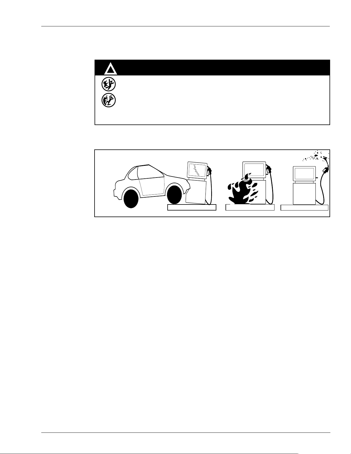
Spilled fuels, ac ciden ts invo lving pump s/d ispen se rs, or uncon trolled fuel flow creat es
a serious hazard.
Fire or explosion may result causing serious injury or death.
Follow established emergency procedures.
The following actions are recommended regarding these hazards:
In An Emergency
WARNING
Collision of Vehicle with Unit Fire at Island Fuel Spill
• Do not go near fuel spill or allow anyone else in the area.
• Use station EMERGENCY CUTOFF immediately. Turn off all system circuit breakers to
the island(s).
• Do not use console E-STOP, ALL STOP to shut o ff power . Th ese keys do not remove AC
power and do not always stop product flow.
• Take precautions to avoid igniting fuel. Do not allow starting of vehicles in the area. No
open flames, smoking or power tools in the area.
• Do not expose yourself to hazardous conditions such as fire, spilled fuel or exposed
wiring.
• Call emergency numbers.
MDE-4363A Atlas Owner’s Manual· March 2005 Page 5
Page 8

Introduction
Introduction
This manual provides instructions for safely operating, programming, and maintaining the
Atlas™ Fuel Systems pumps/dispensers.
Intended User
This manual is written for the owners and operators of Atlas Fuel Systems pumps and
dispensers.
Scope
This manual provides the following information about the Atlas Fuel Systems pumps and
dispensers:
• Operating the pumps/dispensers
• Preparing the pumps/dispensers for service
• Maintaining the pumps/dispensers
Acronym Table
The following table contains a list of acronyms used in this manual.
Note: Refer to the glossary for more detailed definitions.
Acronym Definition
ASC Authorized Service Contractor
CFR Code of Federal Regulations
DLT Displaying Last Transaction
IFSF International Forecourt Standards Forum
MOC Major Oil Company
NEC National Electrical Code
NFPA National Fire Protection Association
OSHA Occupational Safety and Health Association
PIN Personal Identification Number
PPU Price Per Unit (i.e., price per gallon or liter)
STP Submerged Turbine Pump
Page 6 MDE-4363A Atlas Owner’s Manual· March 2005
Page 9
Pump/Dispenser Components
This sectio n provides diagrams that show the internal and external components of pumps and
and provides information about these components. Reference this section as you perform the
procedures in this manual.
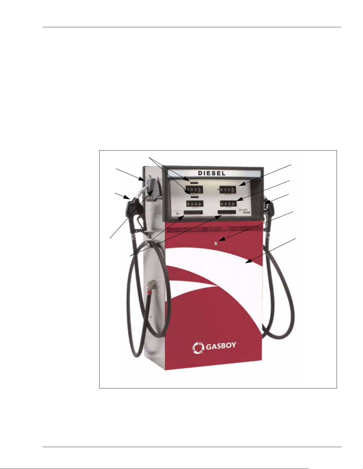
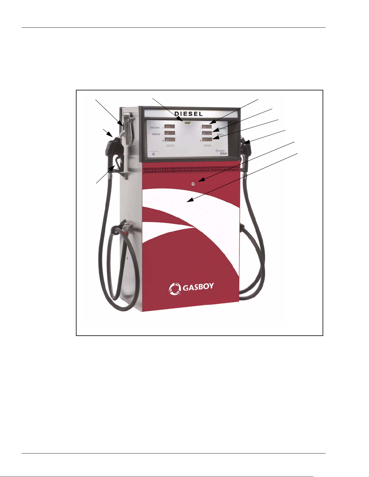
Atlas Pump/Dispenser
The following drawing identifies the external components of a Gasboy Atlas pump/dispenser
(Mechanical Retail Unit). Mechanical units ha ve mechanic al digit al type di splays a s opposed
to electronic digital type displays. In units that are Commercial instead of Retail, the external
components are much the same with the exception that there are only totalizers, PPUs and a
Main Display showing the gallons pumped.
Pump/Dispenser Components
Boot Area
Nozzle &
Pump Handle
Lever Control
PPU Display
Totalizers
Mechanical Retail Unit
Cost Display
Gallon Display
Warning Labels
Door Lock
Access Door
MDE-4363A Atlas Owner’s Manual· March 2005 Page 7
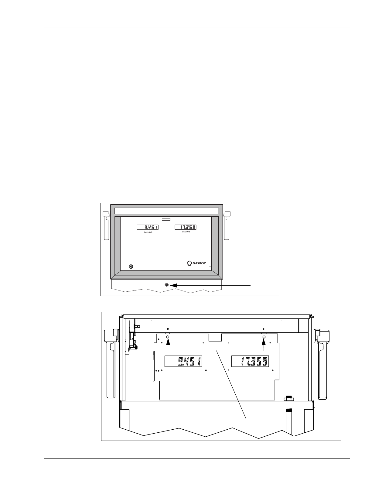
Page 10
Pump/Dispenser Components
The following diagram identifies the external componen ts of a Gasboy Atlas pump/dispenser
(Electronic Retail Unit). Electronic units have digital displays as opposed to mechanical
displays. In units t hat are El ectronic Commercial i nstead of Retail th e externa l components are
much the same with the exception that there are only totalizers, PPUs and a Main Display
showing the gallons pumped.
Boot Area
Nozzle & Pump
Handle
Lever
Control
Electro-Mechanical Totalizer
Electronic Retail Unit
Digital Main Display
Gallons Display
PPU
Warning Label
Door Lock
Access Door
Page 8 MDE-4363A Atlas Owner’s Manual· March 2005
Page 11
Common Functions
This subsection provides instructions for common functions on the Gasboy Atlas pumps/
dispensers.
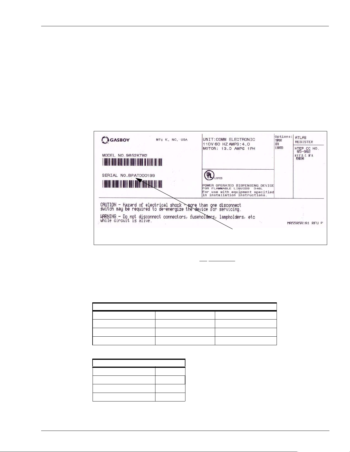
Understanding Date Codes
A two letter date code is stamped on the serial number plate before the serial number. This
code shows the month and year of manufacture. Refer to th e date code to determine the age of
the equipment for wa rr ant y purposes. The serial numbe r pl at e i s located on the “A” side at the
bottom of the unit attached to the inside of the frame.
Common Functions
Serial Number
Example: A serial number plate stamped “BP
AT000199” contains the following information:
• Date code [BP]—This unit was manufactured in B=February P=2005.
• Serial Number [AT000199]
Refer to the following tables to determine the date code on a Gasboy pump or dispenser.
Month Codes
A = January E = May J = September
B = February F = June K = October
C = March G = July L = November
D = April H = August M = December
Year Codes
P = 2005 U = 2009
R = 2006 W = 2010
S = 2007 X = 2011
T = 2008 Y = 2012
MDE-4363A Atlas Owner’s Manual· March 2005 Page 9
Page 12
Common Functions
Pump Totals
Pump totals can be read from the totalizers. At the close of each day’s business, the total c an
be read from the unit and subtracted from the day before to obtain the total for that day. If the
unit is in use 24 hours a day, it may be a good idea to also take the readings in the morning so
as to monitor night usage.
Totalizers
Page 10 MDE-4363A Atlas Owner’s Manual· March 2005
Page 13

Site Preparation
Site Preparat ion
T o ens ur e the sa fety a nd long- term re liabi lit y of your equipmen t, make sur e that your uni ts ar e
properly installed by a knowledgeable ASC. When your units are installed, make sure the
installer takes into consideration the guidelines in the following section.
Obey the Guidelines in Atlas Fuel Systems Documentation and Other Codes
The following manuals provide guidelines for installing Atlas Fuel Systems pumps/
dispensers:
• MDE-4331 Atlas Fuel Systems Installation Manual
• MDE-4333 Atlas Fuel Systems Site Preparation Manual
• FE-356 Atlas Dispenser Wiring Diagram
• FE-357 Atlas Pump Field Wiring Diagram
• FE-361 Atlas Master & Satellite Field Wiring Diagram
Be sure that the installer follows the instructions in those manuals, and adheres to all
applicable local, state and national codes.
General Guidel ines
Be sure the installer, at a minimum, performs the following tasks:
• Attach hose breakaways.
• Follow all manufacturer installation instructions fo r devices attached to the dispenser,
such as hoses, nozzles, and shear valves.
• Install a line leak detection system for all dispensers . (The system must comply with all
local and state codes.)
• Only use UL
• Properly install shear valves for all dispensers and certain above ground tank pump
applications. Be sure to follow all codes.
• Properly bolt units to the island.
• Test hoses for conductivity before use per the manufacturer’s instructions.
• Use appropriate safety signs as outlined in the manuals listed under Obey the Guidelines
in Atlas Fuel Systems Documentation and Other Codes above.
• Use isolation relays for dispensers (required by National Electrical Codes).
• Use the recommended hose lengths for each unit unless you are using hose retrievers.
Note: This is not a complete list. For other requirements, refer the manuals in the above
subsection.
Hoses
Hoses must be UL approved and conductive from end-to-end. Determining hose length is
covered in the table below.
®
-listed or approved attachments with the pump/dispenser.
Note: When determining hose length the effect of adding breakaway s adds significantly to th e
actual hose length.
MDE-4363A Atlas Owner’s Manual· March 2005 Page 11
Page 14
Site Preparation
WARNING
Hoses of excessive length may create a trip hazard.
Serious injury could occur as a result of tripping over an excessively long hose.
Do not use excessive length hoses. Also ensure hose retrievers are installed and
and are in good operating condition.
Do not install soft-wall hoses, they commonly cause a small sale to indicate when the unit is
activated and the nozzle is closed. Refer to the table below for more information about hoses
and hose retrievers.
Determining Hose Length
Refer to the following table to determine the correct hose length for the various types of hoses.
Type Length
Standard hardwall 5/8 or 3/4 ID (without breakaway) 10 feet, 6 inches
Standard hardwall 5/8 or 3/4 ID (with breakaway) 9 feet, 6 inches
Standard breakaway whip hose 1 foot, 0 inches
Install Warning Labels and Signs for Customers
Install wa rning labels and signs to ensure that customers are warned of potential safety
hazards. Make sure the warning label s and si gns ar e rea dily visible. At a minimum, install the
following signs:
• Turn off vehicle before fueling.
• No smoking; do not use matches or lighters nearby.
• Use only non-breakable, approved containers for storing fuel; make sure the container is
metal and properly identified for fuel storage.
• Static electricity hazards during fueling.
Promptly replace any missing, incomplete, or illegible labels or operating instructions.
WARNING
Static electricity can cause an explosion.
Sta tic ele ctricity, inc luding an electrost atic c harge on yo ur body, can ca use a sp ark
sufficient to ignite fuels and their vapors.
After getting out of a vehicle, touch the metal of your vehicle to discharge any
electrostatic charge before you approach the dispenser island.
Page 12 MDE-4363A Atlas Owner’s Manual· March 2005
Page 15
Operating Pumps/Dispensers
This section describes the operation of the pump/remote dispenser. It shows how to:
• access the electronic components
• set the standalone switch
• view and re setting the electronic totalizers
• use the actuator
• use the operating sequences for both pumps and remote dispensers.
If using a point of sale device, reference the manufacturer instructions.
Electronic Component Access (9800 Series Only)
There may be times when you will need to be operated the unit as a standalone. As a
standalone, the pump/dispenser will operate independent of the fuel management system.
1 Unlock and remove the front panel.
2 Remove the two bolts securing the bezel assembly and pivot display panel down.
Operating Pumps/Dispensers
TURN OFF ENGINE
Note: Unit will swing forward and
down after screws are removed.
Atlas
Unlock
Loosen and remove
MDE-4363A Atlas Owner’s Manual· March 2005 Page 13
Page 16
Operating Pumps/Dispensers
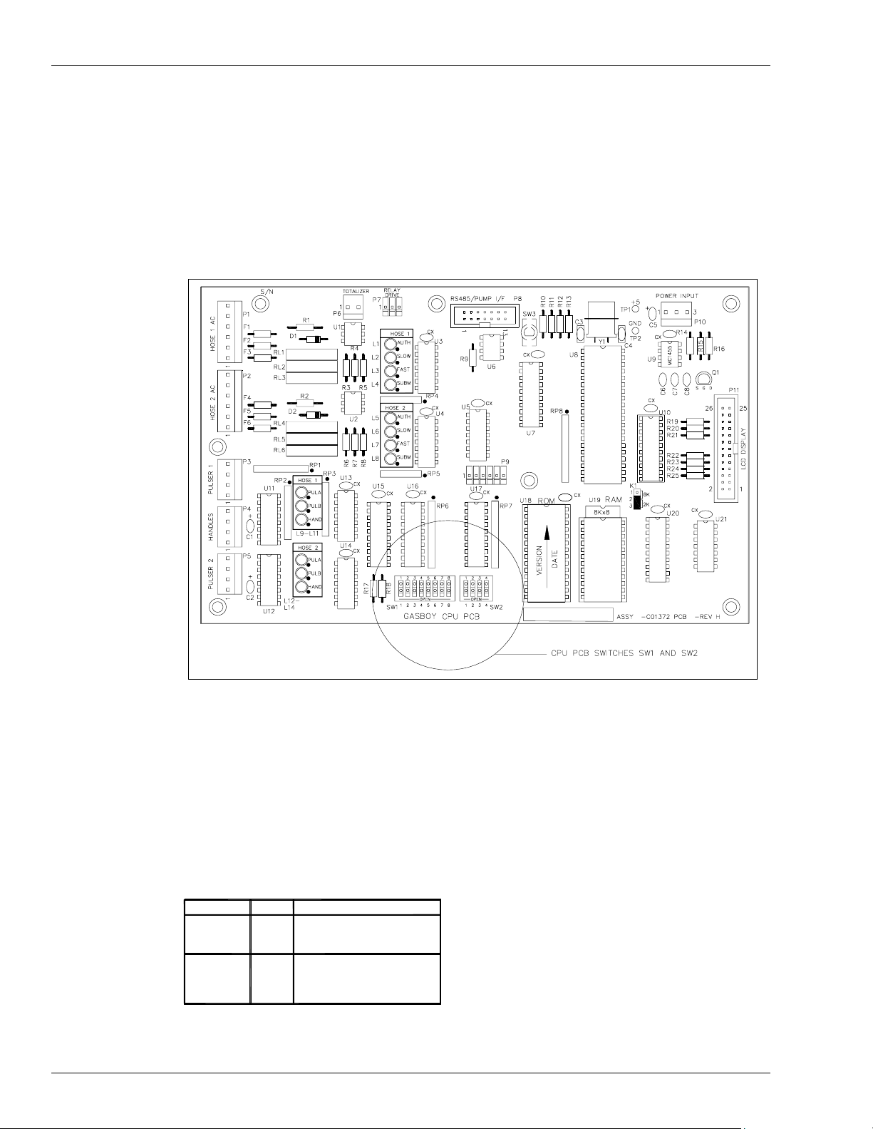
CPU Switch Settings for Standalone Operation (9800 Series Only)
The Atlas can be confi gured for vario us ope rat ing c ondit ions u sing the s witches loca te d on t he
CPU PCB. It is strongly advised that only a Gasboy Service Contractor access any switches
other than those explained here.
Switch settings are only changed with the power OFF. The new settings are read by the CPU
PCB when the power is turned ON again.
CPU Switch Settings (9800 Series Only)
SW1-2 Mode
If the unit is controlled by a GASBOY CFN or Topkat, electronic fuel management system,
the switch should be open (on-l ine mode). If the unit is controlled by a GASBOY Series 1000
or a mechanical system, or controlled by any non-GASBOY system, or not controlled by any
fuel management system at all, the switch should be closed (standalone mode).
Mode
On-line
Standalone
Page 14 MDE-4363A Atlas Owner’s Manual· March 2005
SW1-2
Open
Closed Notcontrolledbyanyfuel
FuelSystem
CFN-ElectronicFuel
ManagmentSystem
managmentsystem
Page 17
3 Onc e the switch set ting has been chang ed, pivot displa y panel to operat ing position and ti ghten
the two screws located on the left and right door support brackets.
4 Place the bezel assembly back into position and secure with the two bolts removed earlier.
5 Place the front panel back into position and lock.
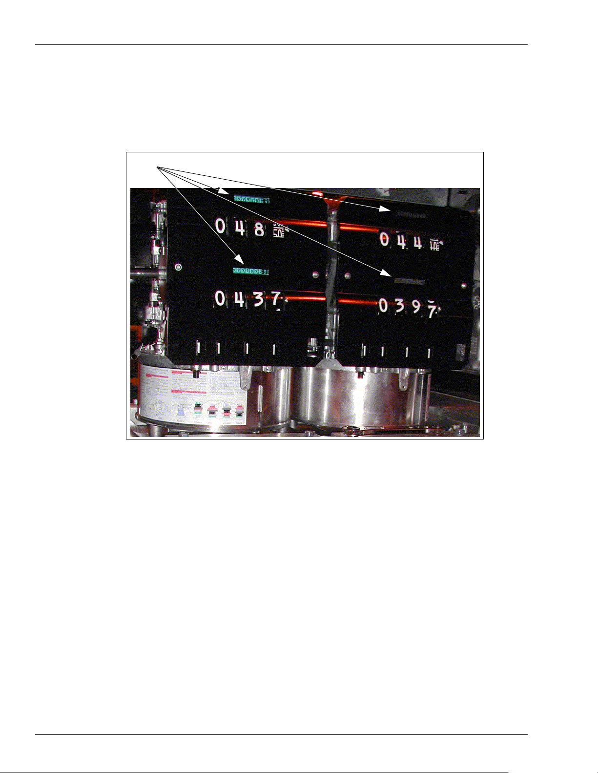
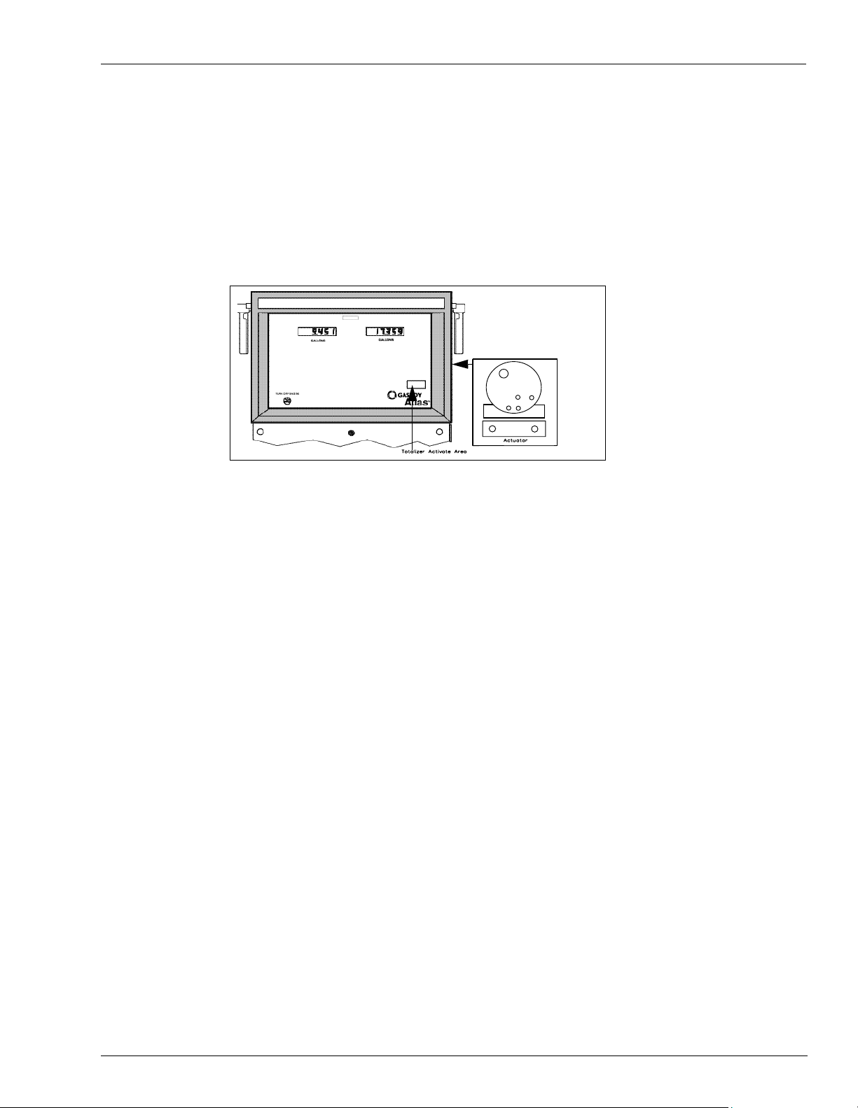
View/Reset Totalizers (9800 Series Only)
Operating Pumps/Dispensers
Commercial Electronic
The Atlas stores a running quantity total for each pump side. These electronic totalizers work
independent of the optional electrical mechanical totalizers that may be installed, and are
shown as whole gallons (liters) on the displays (decimal point is shown, although it is
disregarded). The tota lizer dat a is store d in batter y-backed m emory. The Atlas is supplied wit h
an actuator (shown in the above illustration) which allows you to view and reset electronic
totalizers.
To view the pump totalizers, make sure the pump handles are off and no transactions are in
progress. Locate the GASBOY dial face logo that is on the same pump side as the serial
number tag. (If equipped with the rear totalizer option, the totalizer can be activated from the
GASBOY logo on either side of the pump.) Touch the GASBOY logo with the actuator as
shown. The totalizer data for eac h pump side will be displayed for 10 sec onds . If more time is
needed, touch the actuator to the logo for an additional 10 second period.
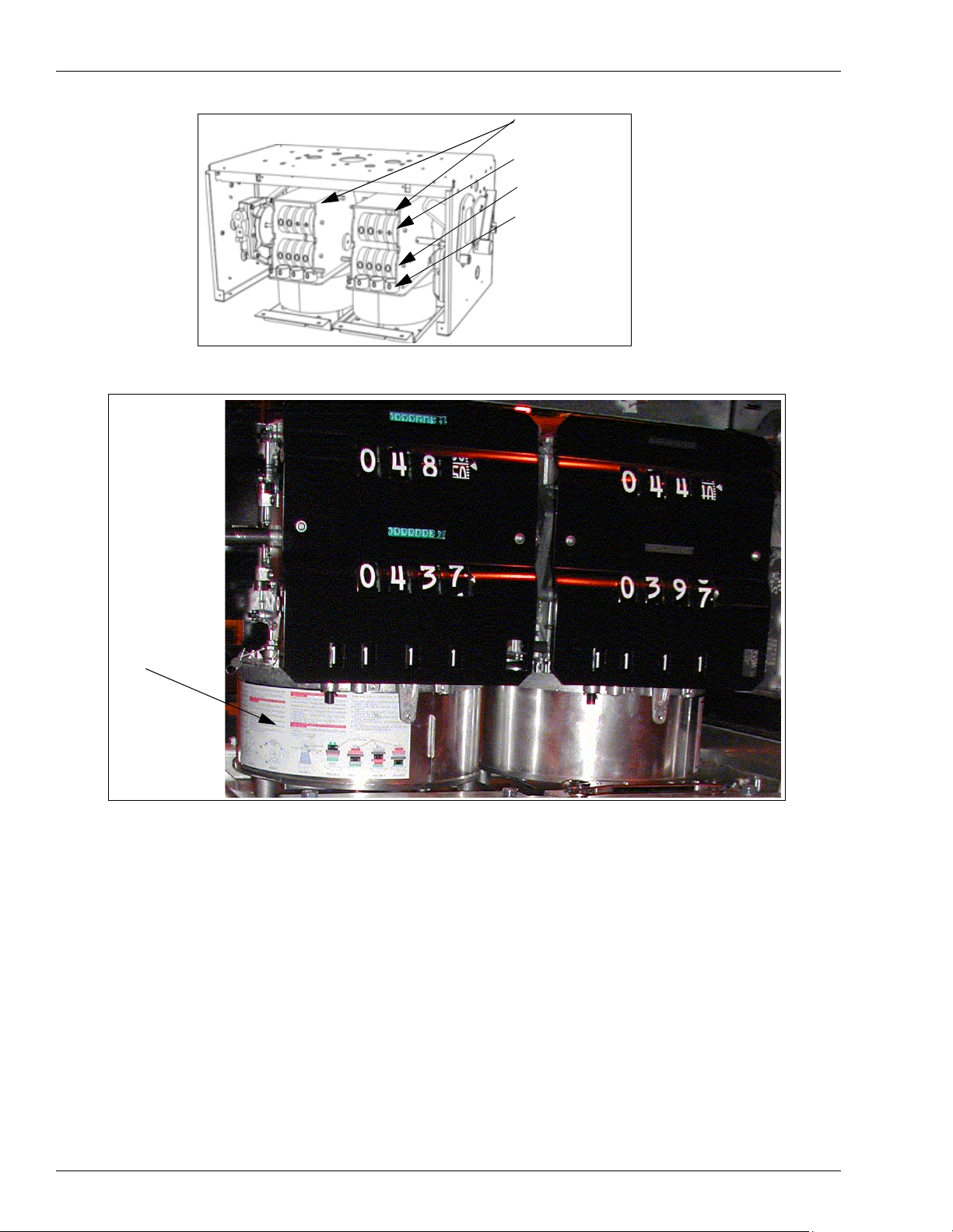
Electro-Mech anical Totalizers
Some models of Atlas contain an optional mechanical totalizer for each pump side. Each
totalizer has 7 digits; 6 whole gallons and 1 tenth-wheel, 7 whole digits for liters. The electromechanical totalizers are located below each nozzle hook. Reference Atlas Pump/Dispenser,
Page 7.
MDE-4363A Atlas Owner’s Manual· March 2005 Page 15
Page 18
Operating Pumps/Dispensers
Note: Directions
for changing the
price can be
found on the
outside of the
variator cover.
Mechanical Totalizer
Totalizers
Dollars/Cents
Gallons/Liters
PPU (Price Per
Unit)
NOTE: The unit shown to
the left is an example of a
one type of Totalizer, the
example shown is a
Mechanical Totalizer and
as such is used only in
mechanical units.
Variator
Changing the Price
1 Unlock and remove the front panel. Repeat this procedure for the other side.
2 The variator section of the computer register(s) is exposed to allow for price changes. Slide the
variator cover of the computer register apart to expose the price range arms.
3 To change a setting, grasp the desired range arm (tenths of a cent, one cent, and ten cent arm)
and raise it to clear the range arm locator, move it f oreward or backwards, relocating it at the
desired position so that the range arm is station at it’s new location on the range arm locator.
Assure the range arm is totally bottomed on its setting. Repeat this for all range arm settings if
necessary.
Page 16 MDE-4363A Atlas Owner’s Manual· March 2005
Page 19

Operating Pumps/Dispensers
Range Arm
Range Arm Locator
4 To change the money unit setting, locate the lever control which is located above the variator
section on the same leve l as the price displ ay. There are 3 availa ble posi tion s: 0.00, 1.00 , 2.00.
Remove the cotter pin, grasp the lever and raise it slightly to clear the position locators.
Position the lever to the desired setting and release. Reinsert the cotter pin through the lever
and plate. Note - If the lever wil l not move to the des ired pos iti on, rotat e the ri ght han d money
wheel until the lever is free to move.
5 If you have difficulty reaching the money shift lever when changing prices, remove the two
cap screws located over the tabs of the bezel assembly. Lift the bezel assembly upward and
remove it from the unit. When reattaching the bezel to the dispensing unit, be sure the top
inner edge of the bez el ass embl y sl ides into the "U" shaped chan nel loc at ed on the upper edge
of the dispensing unit.
MDE-4363A Atlas Owner’s Manual· March 2005 Page 17
Page 20

Operating Pumps/Dispensers
Programming 8800 Models
General Programming
Programming the unit is divided into three levels; Level 1, 2 and 3. Level 1 codes will be
explained here. The default code for level 1 is 2222. This code can be changed for station
security, however losing the codes will require a master reset of the unit and reprogramming.
Codes found in Level 1 are included below.
• CC 1 Manual programming of PPU (unit pricing). Pricing can also be downloaded
through the two-wire communication using the POS (Point Of Sale) device.
Note: Levels CC 2 & CC 3 should only be accessed by a trained ASC or improper operation
could result.
• CC 2 Setting mode of operation as being stand alone (isolates sale control from the POS)
or two-wire (unit control through the POS).
• CC 3 Programming Volume Allocation. This basicall y set s the max imum sale size i n unit s
of measure (gallons for example).
• CC 4 Manual Blank and Five-Button Preset. This dual use code allows turning the
displays off manually or is used to activate different preset modes depending upon the
options included with the unit.
• CC 5 Test Programmable Customer Preset. This code is used to initiate testing for the 5
Button Preset option if used.
• CC 6 Memory Clear: This code is only useful to clear a unit displaying an Error Code EC
31 Totals Data Error) or EC 35 Configuration Data Error.
• CC 7 Setting Totals Input. This code allows setting of non zero totals. It is useful for new
installs or service when the station does not want to restart totals for its dispensers at zero
when old dispensers are replaced or receive certain types of service. It can only be
performed after performing a master reset, CC7 or for new units.
• CC 8 display Pump Controller Firmware Version.
Programming the 8800 Series Retail Electronic Units
This section describes the level 1 programming procedures and considerations for the 8800
series.
Page 18 MDE-4363A Atlas Owner’s Manual· March 2005
Page 21

Operating Pumps/Dispensers
Conversion Factor
US Gallons
Imperial Gallons
Liters
1012 Pulses per Gallon
Memory Error
ROM Error
RAM Error
Sides
Single-sided
Dual-sided
Code
0
1
2
3
Code
1
2
Code
1
2
Level 1 Programming and Data Access (8800 Series only)
Pin Code Entry
Unit T ype
1 Grade
2 Grade
3 Grade
4 Grade
Two Wire Pump ID 1-16
Code
0
1
2
3
Press Fl.
Enter 4-digit ID (default 2222) than press ENTER.
Press F1 to exit any command code.
Press F2 to return to normal operation.
From Level 1 after entering pin code (you may enter any command code directly):
Command Code 1: Pr ogram PPU
• Press "1' and then ENTER
• Select Side (1 or 2) and then ENTER
• Select Grade and then ENTER
• Select Price Level and then ENTER
• Enter new PPU and then ENTER
(Repeat for other Side, Grade and Price Level)
Command Code 2: Program Two-Wire/Standalone
• Press “2" and then ENTER
• Press Configuration number and then ENTER where
0 = Standalone
1 = Two-Wire
MDE-4363A Atlas Owner’s Manual· March 2005 Page 19
Page 22

Operating Pumps/Dispensers
Command Code 3: Program Allocation
• Press '3’ and then ENTER
• Select Side (1 or 2) and then ENTER
• Select Hose/Grade and then ENTER
• Select Allocation amount and then ENTER
(Repeat for other Side, Hose and Grade.)
Command Code 4: Program Manual Blank Display Cash/Volume Preset Select
• Press "4" and then ENTER
• Select Function Code (1 or 2) and then press ENTER where
Function Code 1: Manual Blank Displays
Press option code and then ENTER where
0= Display OFF
1= Display ON
Function Code 2: Cash/Volume Preset Select (requires option on dispenser)
Press option code and then ENTER where
0= No 5 Button Preset or PPP Preset installed
1= Money Preset
2= Volume Preset
3= Incremental Preset
Command Code 5: Test Customer Programmable Preset (Requires preset optoin on dispenser)
• Press "5" and then ENTER.
• Select Configuration and then ENTER where
0= STOP Test/Program
1= START Test/Pr ogram
Depending upon the preset option type testing will convey the following when pressing the pr eset
buttons:
Five Button Preset (Non-Customer Programmable Preset) (Requires preset option on unit)
Press ENTER after making selections.
1: Program Button 1 (Default 1)
2: Program Button 2 (Default 5)
3: Program Button 3 (Default 10)
4: Program Button 4 (Default 15)
Page 20 MDE-4363A Atlas Owner’s Manual· March 2005
Page 23

Operating Pumps/Dispensers
Incremental Preset (Non-Customer Programmable Preset) (Requires preset option on unit)
Press ENTER after making selections.
1: Program Button t (Default 1) Money
2: Program Button 2 (Default 5) Money
3: Program Button 3 (Default 10) Money
4: Program Button 1 (Default 1) Volume
5: Program Button 2 (Default 5) Volume
6: Program Button 3 (Default 10) Volume
(After test is complete follow programming steps to setup)
Command Code 6: Memory Clear For Error Code 31 or 35
• Press ”6" and then ENTER
• Press “1” and then ENTER
• Command Code 7: Program Totals Input
• Press “7” and then ENTER
• Select Side (1 or 2) and then ENTER
• Select Grace # and then ENTER
• Press “$ Total”
• Enter money total and then ENTER
(Repeat for other side and grade)
Press “Volume Total” AND repeat above procedure for volume totals.
Command Code 8: Display Version Number
• Enter "8" and then ENTER
• Select Software Option and then ENTER where
1= Pump Controller
3= Customer Programmable Preset
MDE-4363A Atlas Owner’s Manual· March 2005 Page 21
Page 24

Operating Pumps/Dispensers
ATC Programming (8800 Series Only)
At Power-up, units programmed with the ATC option will flash 104 before displaying normal
information. Units with the option but not programmed for ATC will flash 100. The
following procedure is used to program the ATC option:
1 Turn the programming switch on the ATC controller board to “ON”. Note the dispenser must
not be used during this programming and all pump handles must be down or inactive.
2 Press 100 on the keypad, then ENTER
• The money position showing fueling position selected will display 1
• The volume position showing the fuel type selected will display 1 where
a.1= Gasoline
b.2= Diesel
• The PPU position showing fuel density selected will display 730 where
a. 740= Gasoline
b. 840= Diesel
c. Default= 730
3 Select the fuel type and press ENTER
4 The firmware sequence will sequence through each fueling position. Select the fuel type for
each positi on (Diesel or Gasolin e).
5 Turn the programming switch on the ATC controller board to OFF.
6 Press F2 to exit the ATC programming mode.
ATC Inspection Mode (8800 Series Only)
Inspection of ATC states and data collection can be obtained following a similar procedure as
outlined for ATC programming above. Instead of pressing “100” other codes can be used as
described in the following table:
Page 22 MDE-4363A Atlas Owner’s Manual· March 2005
Page 25

Displaying Pump Totals (8800 Series Only)
Operating Pumps/Dispensers
During service it i s of te n required to access pump tota ls. This can be done at the POS or at the
pump/dispenser. Access is simple through the manager keypad:
To view Side 1 totals:
1 Press $TOTAL. Combined cash and credit total will display for grade 1, side 1.
2 Select grade. Read $TOTAL for each grade selected.
3 Press VOL TOTAL. The Volume total will display for the grade selected.
4 Select grade. Read volume totals for grade selected.
5 To view Side 2 totals, press Enter.
6 Press Clear to exit.
Error Codes and Interpretations for 8800 Retail Electronic Units
You may observe t he following. The se codes ar e useful when troubles hooting a pr oblem. Side
A is the Junction box opening side, B is the opposite side.
31 Totals data error - can be cleared through CC 6 programming (reference Pr ogr amming -
8800 series units. If codes repeat frequently, consult a Gasboy ASC.)
35 Configuration Data Error - can be cleared through CC 6 programming (reference
Programming - 8800 series units. If codes repeat fr eque nt ly, consult a Gasboy ASC.)
44 Pump Handle Up at Power Up
To recover, lower pump handle.
MDE-4363A Atlas Owner’s Manual· March 2005 Page 23
Page 26

Operating Pumps/Dispensers
S0000349
Shear Valve
Shear valves, require d by NFPA 30A, are intended to shut-of f t he f low o f f uel at the di spenser
base (hydraulics area ) during vehicl e impact or fir es. A single-poppe t shear valve pr events fuel
from flowing from the underground tank. A double-poppet shear valve prevents fuel from
flowing from the underground tank and draining from the dispenser. In the event that product
fails to exit the dispenser/pump hose, check to ensure that the shear valve is not closed.
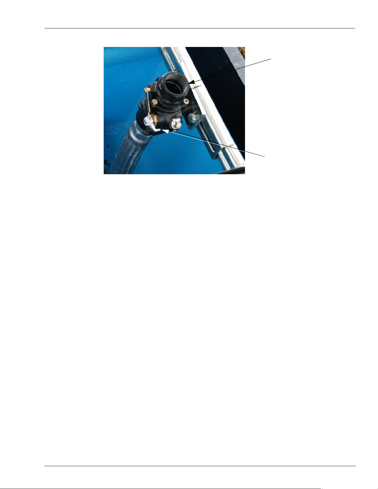
The following diagram shows a shear valve, in the open position (allows flow to pass
through). Note it’s location inside the dispenser on the lower cross brace in the pit box area.
Shear Valve in
Open Position
Shear Valve
Lower Cross Brace
WARNING
Shear Valves may stick partially in the open position causing fuel to flow
throug h a she ar val ve tho ught t o be cl osed. Alway s tes t for proper closing
by attempting to dispense fuel into an approved container with the fuel
position authorized. Fuel most not continue to flow after pressure has
been reli ev ed.
For maintenance information, reference the Preventive Maintenance Table, Page 34 of this
manual.
Page 24 MDE-4363A Atlas Owner’s Manual· March 2005
Page 27
Operating Sequence (9800 Series Only)
Operating Pumps/Dispensers
Shear Valve
Shear Valve in the OFF (Closed)
position
The exact sequence of ev ents that occu rs duri ng the opera tion of the pump or remote dispe nser
is determined by various switch settings, inputs, and the user. A typical transaction is
explained below.
Pump Unit - (motor and pump in unit base)
1 Turn on the pump handle. If AC is present on the Control Feed line, the reset cycle begins.
The display (electronic units):
• goes blank for one second
• shows all 8's for one second
• goes to 0.000 (gallons) or 0.00 (liters) until fuel starts.
The display (mechanical units)
• resets to 0.000 (gallons) or 0.00 (liters)
The pump motor turns on and the Reset Complete line becomes active.
2 The pump continu es to run un til on e of the fo llowing co nditions o ccurs. These condi tions tur n
off all relays.
• The handle is turned off.
• The Control Feed line (AC power line to pump/dispenser) is turned off by the POS.
• A pulser error is detected (electronic units only).
• A time-out is reached (if the unit is programmed with a time out value (9800 series only).
If connected to a fuel management system, the time-out loaded into the system will be
used (comm ercial electronic only). Unit will turn off if idle for a preprogramming ti me
when no fuel is flowing.
• A quantity of 990.000 gallons (9900.00 liters) is reached. If connected to a fuel
MDE-4363A Atlas Owner’s Manual· March 2005 Page 25
Page 28

Operating Pumps/Dispensers
management system, the limit set in the system will be used. (9800 Series O nly)
• The pump is halted by an operator of a fuel management system.
• An AC power failure occurs.
• Station Emergency Stop button is pressed.
Dispenser Unit- (fueling unit with no motor and pump in the bottom)
1 Turn on the pump handle. If AC is present on the Control Feed line, the re set cycle begi ns and
the submersible pump turns on. The display (Electronic Unit):
• goes blank for one second
• shows all 8's for one second
• goes to 0.000 (gallons) or 0.00 (liters) and stays until fueling begins.
The display (mechanical units)
• resets to 0.000 (gallons) or 0.00 (liters)
2 The user begins to dispense fuel.
3 The remote dispenser continues to run until one of the following conditions occurs. These
conditions turn off all relays.
• The handle is turned off.
• The Control Feed line is turned off (AC power line to pump/dispenser) is turned off at the
POS.
• A pulser error is detected (electronic unit only).
• A time-out is reached (if the unit is pr ogrammed wit h a time out val ue)(8 800 Serie s Unit).
If connected to a fuel management system, the time-out loaded into the system will be
used (commercial electronic only)(9800 Series Unit). Unit will turn off if idle for a
preprogrammed time when no fuel is flowing.
• (9800 models) A quantit y of 99 0.000 gal lons ( 9900.00 lite rs ) is rea ched. I f conn ected to a
fuel management system, the limit set in the system will be used.
• The pump is halted by an operator of a fuel management system.
• An AC power failure occurs.
• Station Emergency Stop button is pressed.
Standalone Mode Error Handling (Commercial Electronic Unit) (9800 Series Unit)
When operating the pump/dis p en ser in sta nda lone mode (not connected to a fuel mana gemen t
system), the Atlas displays two-digit error transaction codes on the LCD displays when
transactions are terminated abnormally (by a means other than turning off the pump handle).
There are four possible error conditions that may be displayed:
Code Condition
55 Po wer fai lure
56 Pu lser error
57 Timed out
58 Limit cutoff
Page 26 MDE-4363A Atlas Owner’s Manual· March 2005
Page 29

The error codes are displayed for two seconds at the left of the LCD window, alternating with
a five-second display of the last sale amount. The display alternates between the two until a
new transaction begins. When an error occurs, the user should note the error code and relay
the information to the ASC.
Transac tion error cod es are displa yed only when the pump/ dispenser is op erating in st andalone
mode. When connected to a fuel management sys tem, (on-l ine mode) , transa ction error co des
are transmitted back to the fuel management system with the completed transaction data.
Safety Information
Refer to Important Safety Information, Page 3 for safety information before operating pumps/
dispensers.
Operating Pumps/Dispensers
WARNING
Running vehicles can generate sparks, which could ignite fuel.
Running vehicles could create a safety hazard, such as a fire or an explosion.
Never dispense fuel into a vehicle with its motor running.
MDE-4363A Atlas Owner’s Manual· March 2005 Page 27
Page 30

Preparing for Servicing the Pumps/Dispensers
Preparing for Servicing the Pumps/Dispensers
This section provides instructions for preparing your site for servicing by a Gasboy-trained
ASC.
WARNING
The pump/dispenser contains pressurized flammable fuel and lethal voltages.
Servicing a Gasboy unit incorrectly could result in severe injury or death.
Do not attempt to service Gasboy pump/dispenser yourself, and do not allow
untrained pe rsonnel to service Gasboy pumps/dispensers. Only Gasboy-trained
ASCs should service a Gasboy unit.
WARNING
Unapproved modifications could result in hazardous conditions.
Making unapproved modifications could result in improper equipment operation and
violation of state and local codes and could also create a hazardous condition, such
as fire, explosion, or electrical shock.
Do not make unapproved modifications to Gasboy equipment. Consult your ASC,
distributor, or Gasboy for approved modifications and kits.
Call Gasboy First
Before phoning an ASC, call the Gasboy help desk at 1-800-444-5529. The help desk may be
able to resolve the issue for you.
Service Preparation
Use a Gasboy-tra ined ASC to e f fi cient ly s ervice and main tain you r Gasbo y p umps/di spense rs.
Gasboy trains and certifies ASCs to service and maintain Gasboy pumps/dispensers in a safe
manner.
Before Calling For Service
Perform the following tasks bef ore you call for service:
• Obtain complete information from station personnel about the problem.
• Confirm that the tank has fuel.
• Confirm that the power, pump lights, and circuit breakers are on.
• Record Error Codes that may exist on the Main Display (Elec tronic Units only).
Description of Problem
Provide the ASC with a complete pro blem descri ption includi ng all symp toms. Be sure to give
the serviceman as complete and accurate information. Doing so will help ensure faster repairs
and keep downtime costs to a minimum.
Page 28 MDE-4363A Atlas Owner’s Manual· March 2005
Page 31

Warranty Service
All warranty service must be performed by an ASC, failure to do so could result in loss of
warranty coverage.
Replacement Part s
Use only genuine Gasboy replacement parts and retrofit kits on your pump/dispenser.
Preparing for Servicing the Pumps/Dispensers
WARNING
Non-Gasboy replacement parts may create safety hazards and violate local
regulations. Non-Gasboy replacement parts could also affect the pump/
dispenser’s performance, reliability, and warranty.
Use of non-Gasboy replacement parts could create a hazardous condition, such
as fire, explosion, or electrical shock.
Only use Gasboy replacement parts and retrofit kits.
Specialized Training
For safety reasons, do not attempt to service Gasboy pu mp/di spense r yours elf un less y ou have
been trained and certified by Gasboy or an authorized Gasboy certified trainer.
WARNING
The pump/dispenser contains pressurized flammable fuel and lethal voltages.
Servicing a Gasboy unit incorrectly could result in severe injury or death.
Do not attempt to service Gasboy pump/dispenser yourself, and do not allow
untrained pe rsonnel to service Gasboy pumps/dispensers. Only Gasboy-trained
ASCs should service a Gasboy unit.
To receive specialized training for servicing Gasboy pumps/dispensers, contact a Gasboytrained contractor or distributor. Training may be available locally, at various regional centers.
Contractors and distri butors may char ge a nomin al trai ning fe e. For more inf ormati on, conta ct
your nearest distributor.
MDE-4363A Atlas Owner’s Manual· March 2005 Page 29
Page 32

Preventive Maintenance
Preventive Maintenance
Gasboy pumps and remote dispe nsers are designed for many years of re liable service , however
certain dispenser or pump parts will experience normal wear and therefore will require
periodic inspections. For example, detecting fuel leaks that may occur, belt tension and belt
condition, lubrication and strainer cleanliness are all important to maintain safe and efficient
unit operation. To avoid annoying pump shut downs, a periodic preventive maintenance
inspection plan must be established and followed.
Procedures requiring leak repair, shear valve maintenance and disassembly of portions of the
pump/remote dispenser should be performed by an ASC.
WARNING
To avoid electrical shock or hazard of an explosion or fire, when servicing remote dispenser/
pump:
- turn off and lock out all power to the pump/remote dispenser. (In submersible pump
applications turn off and lock out power to the submersible pump and any other remote
dispensers which use that su bmersibl e pump. AC power can feed back into a shut-of f disp enser
when remote dispensers share a commo n subm ersib le pum p or st arte r relay.)
- turn off and lock out all power to the remote dispenser and submerged pumps at the master
panel and clo se and te st a ny im p ac t v al ve before performing any main ten anc e or service to the
remote dispenser, including changing any fuel filters or strainers.
- block island so no vehicles can pull up to the remote dispenser when the dispense is being
worked on.
CAUTION
Moisture from rain can damage the internal components of a pump/dispenser.
Internal components exposed to moisture may not operate correctly.
Do not open the elec tronics cabinet to per form any tasks while it is raining.
Maintenance of Vender Supplied Parts
Certain parts of t he d is p ens er /pu mp ar e pr odu ced by venders for Gasboy (h ose s, nozzles, etc.)
and as such may have docume ntation sepa rate fro m that which Ga sboy suppli es. In thes e cases
it will be necessary to consult the vender documentation for service intervals and any
adjustments if required to your dispenser/pump.
Use Authorized Parts
The use of unauthorized parts can void your warranty, cause you to lose continuity of the
Underwriters Label on the pump, cause inefficient operation and possibly an operational
hazard. Always use new gaskets and seals when servicing or rebuilding Gasboy equipment.
Page 30 MDE-4363A Atlas Owner’s Manual· March 2005
Page 33

Performing Inspections
This section provides instructions for scheduling two types of maintenance inspections:
• General inspections
• Component inspections
Safety Warnings
You are performing inspections and maintenance in a potentially dangerous environment of
flammable fuels/v apors and hi gh volt age . Foll ow all safet y p recaut ions to pre vent i njur y whe n
inspecting a pump/dispenser at the islands.
WARNING
You are performing inspections and maintenance in a potentially dangerous environment of
flammable fuels/vapors and high voltage.
Fire, explosion, or electrical shock could result in severe injury or death if you do not follow
safe procedures.
WARNING
Read and obey all safety precautions in this manual to prevent potential injury or death.
Preventive Maintenance
General Inspections
Perform a general inspection of each pump/dispenser as follows:
• Each week to ensure that all pumps/dispensers are operating properly
• Whenever you receive a complaint about potential unit problems
As part of your general inspection, inspect all areas for signs of damage or sharp edges.
Replace any missing or damaged warning labels. Gasboy also strongly recommends that an
ASC periodically inspect the equipment, as outlined in the next subsection.
WARNING
Leaking fuel can be ignited, causing a fire or explosion.
Fire, explosion, or electrical shock could result in severe injury or death if you continue to use
damaged pumps/dispensers.
If you find any leaks or damage, stop using the pump/dispenser, and contact your local ASC.
WARNING
Personnel servicing a pump /dispe nser c an be in jured i f the pum p/dis pense r is not barrica ded to
all unauthorized personnel and vehicles.
If proper precautions are not taken, the person servicing the unit can be injured by a vehicle.
Before servicing a pump/dispenser, evacuate all unauthorized persons and vehicles; then, use
safety tape or cones as barricades.
MDE-4363A Atlas Owner’s Manual· March 2005 Page 31
Page 34

Preventive Maintenance
Component Inspections
Refer to the Preventive Maintenance table to schedule component inspections. The station
owner should only inspect for problems. For safety reasons, several tasks in the Preventive
Maintenance Table, Page 34, including all repairs, should be performed only by an ASC.
Refer to the column entitled “Who Performs the Inspection/Repair” to determine if an ASC
must perform a task.
WARNING
The pump/dispenser contains pressurized flammable fuel and lethal voltages.
Servicing a Gasboy unit incorrectly could result in severe injury or death.
Do not attempt to s erv ic e G asboy pump/dispenser you rse lf, and do not allow untrained personne l
to service Gasboy pumps/dispensers. Only Gasboy-trained ASCs should service a Gasboy unit.
WARNING
Leaking fuel can be ignited, causing a fire or explosion.
Fire, explosion, or electrical shock could result in severe injury or death if you continue to use
damaged pumps/dispensers.
If you find any leaks or damage, stop using the pump/dispenser, and contact your local ASC.
CAUTION
Improperly installed or maintained e quipment can create a hazard.
Improperly installed or maintained equipment could cause a fire, explosion, or electrical shock.
For any component not supplied by Gasboy (for example, hoses and nozzles), consult and follow
the installation and maintenance instructions provided by the manufacturer.
Filter Strainer Replacement
If the unit is equipped with a straine r and filter, check and change it at regular intervals (see
maintenance table). A dirty strainer and or filter in a pump or remote dispenser will cause a
slower delivery rate. Refer to the accessories section of your parts manual to ensure that you
replace the strai ner of re quired and filter with one d esi gned for your model. Always use a d ri p
pan and abso rbent material directly b elow the filter when removing the cartridge to prevent
contamination of both the soil and the electrical components within the cabinet. This service
must not be done by untrained individuals.
Page 32 MDE-4363A Atlas Owner’s Manual· March 2005
Page 35

Special Setup Required for Aircraft Fueling
CAUTION
Aircraft require finely filtered fuel.
Improperly filtered fuel could cause the engine to fail.
Do not use Gasboy pu mp s/d ispense rs for di rect f ueling of a ircraft wit hout a uxiliary
filters, separators, and other equipment necessary to ensure product purity.
Adjusting the Belts (Suction Pumps Only)
With the proper care, belts will give exceptionally good service. A loose belt not only cuts
down dispensing speed, due to slipping, but also results in excessive wear. Reference the
Preventive Maintenance Table, Page 34 found in this manual. This service must not be done
by untrained individuals.
Preventive Maintenance
Preserve the Finish of Your Pumps
Nearly all gasoline pumps are installed outdoors where their surfaces are subjected to the
weather condition s. As a resul t, it is necessar y to give t he finis h a reason able amount o f care if
an attractive appearance is to be maintained.
The finish on Gasboy pump housings is a high-heat baked synthetic enamel, similar to that
used on automobiles. The life of this finish can be lengthened several years if, at regular
intervals, the pain te d surfac es are th oroughl y cleane d wit h a high grade automo bile pol ish and
then protected with a coat of paste wax. Do not use abrasive cleaners or polish. Do not use
high pressure sprayi ng equipment . Do not use win dow cleaner with ammonia o n the elec tronic
display.
In order to retain the unmarked finish on stainless steel, occasional cleaning is required. In
corrosive atmospheres, such as coastal areas, a more frequent cleaning schedule is necessary.
Under ordinary conditions, washing with detergent or soap and water, followed by a clean
water rinse, is sufficient. If hard water is used, the surface should be wiped dry with a soft
clean cloth to prevent the formation of water spots. Marks or spots, such as grease, oily
fingerprints and smudges which resist soap and detergents, will have to be removed with a
stronger cleaner. (DO NOT us e ordi nary s teel wool a s iro n part icle s may adher e to the su rface
and cause corrosion.) Care should be taken in choosing a cleaner because any cleaning
compounds or powders which contain abrasives can scratch a mill-rolled finish. Care must be
exercised that any polishing is done with the lines in the steel, never across them. After
cleaning, an application of paste wax is recommended to protect the surface and prolong the
interval between cleani ng.
.
MDE-4363A Atlas Owner’s Manual· March 2005 Page 33
Page 36

Preventive Maintenance
WARNING
.
Preventive Maintenance Table
Re c o mm e n d ed
Components
Stainless Steel
sheathing and lower
doors
Hoses, swivels At lease once a
Frequency Recommended Maintenance
Monthly For stains on stainless steel, use a cleaner specifically
week or if a
customer complaint
arises
formulated for cleaning stainless steel. Gasboy recommends
Barkeepers Friend. Be sure to thoroughly rinse off all cleaner.
Be sure not to spray water/cleaner directly at or into card
readers, cash acceptors, or printer chutes.
1 Inspect each hose for leaks abuse and excessive wear.
Leaking fuel can be ignited, causing a fire or explosion.
Fire, explosion, or electrical shock cou ld res ult in sev ere injury or
death if you continue to use damaged pumps/dispensers.
If you find any l eaks or d amage, st op using the pump /dispenser, and
contact your local ASC.
2 Inspect each hose, break away, whip hose, and vapor hose
for the following wear or damage:
• Bulges
• Cracks
• Damage
• Flattened spots
• Holes
3 Make sure vapor recovery hoses do not touch the ground
when the nozzle is seated properly in the nozzle boot.
4 Consult the manufacturer for any additional inspections
required.
5 If repair is needed, call an ASC to make the repairs.
Reinforcement showing
- Soft spots
- Tears
- Weaknesses
- wear through
Who Performs the
Inspection/Repair
Once every three
months (in harsh
environments once a
month)
• Owner—Inspect
• ASC repair and test
• Owner—Inspect
• ASC repair and test
WARNING
The pump/dispenser contains pressurized flammable fuel and lethal voltages
Servicing a Gasboy unit incorrectly could result in severe injury or death.
Do not attempt to service Gasboy pump/dispenser yourself, and do not allow
untrained personnel to service Gasboy pumps/dispensers. Only Gasboytrained ASCs should service a Gasboy unit.
WARNING
Hoses of excessive length may create a trip hazard.
WARNING
Serious injury could occur as a result of tripping over an excessive
length hose.
Do not use excessive length hoses.
Hose retrievers Once a week or if a
customer complaint
arises
1 Inspect hose retrievers for frayed or broken cables.
2 Inspect hose retrievers for cables wrapped around hoses.
3 If repair is needed, call an ASC to make the repairs.
Page 34 MDE-4363A Atlas Owner’s Manual· March 2005
• Owner Inspect
• ASC repair and test
Page 37

Preventive Maintenance
Components
Nozzles and boot area Once a week or as
Re c o mm e n d ed
Frequency Recommended Maintenance
notified about a
potential problem
Who Performs the
Inspection/Repair
WARNING
The pump/dispenser contains pressurized flammable fuel and lethal
voltages.
Servicing a Gasboy unit incorrectly could result in severe injury or death.
Do not attempt to service Gasboy pump/dispenser yourself, and do not
allow untrained personnel to service Gasboy pumps/dispensers. Only
Gasboy-trained ASCs should service a Gasboy unit.
WARNING
Hoses that are not recoiled properly create a trip hazard.
Serious injury could occur as a result of tripping over an excessive
length hose.
Repair or replace broken hose retrievers promptly.
1 Inspect nozzles for the following wear or damage:
• Damage
• Leaks
• Loose nozzle spouts
• Missing parts, such as retainer springs and splash guards
• Owner—Inspect
• ASC only—Repair
and test
WARNING
Leaking fuel can be ignited, causing a fire or explosion.
Fire, explosion, or electrical shock could result in severe injury or
death if you continue to use damaged pumps/dispensers.
If you find any lea ks or damag e, stop us ing the p ump/dis penser, and
contact your local ASC.
2 Inspect vapor recovery boots (bellows) for proper seal and
damage.
3 Consult the nozzle manufacturer for any additional required
inspections.
4 If repair is needed, call an ASC to make the repairs.
WARNING
The pump/dispenser contains pressurized flammable fuel and lethal
voltages.
Servicing a Gasboy unit incorrectly could result in severe injury or death.
Do not attempt to service Gasboy pump/dispenser yourself, and do not
allow untrained personnel to service Gasboy pumps/dispensers. Only
Gasboy-trained ASCs should service a Gasboy unit.
MDE-4363A Atlas Owner’s Manual· March 2005 Page 35
Page 38

Preventive Maintenance
Components
Leaks, external Once a week, or as
Re c o mm e n d ed
Frequency Recommended Maintenance
notified about a
potential leak
Who Performs the
Inspection/Repair
1 Inspect the following for any signs of damage or leaks, such
as cracks and cuts,:
• Couplings
• Hose outlet castings
• Swivels
2 Review all documentation provided by each component’s
manufacturer.
3 If a leak is found, stop using the pump/dispenser, and make
arrangements to repair the leak.
• Owner—Inspect
• ASC only—Repair
and test
WARNING
Leaking fuel can be ignited, causing a fire or explosion.
Fire, explosion, or electrical shock cou ld res ult in sev ere injury or
death if you continue to use damaged pumps/dispensers.
If you find any l eaks or d amage, st op using the pump /dispenser, and
contact your local ASC.
WARNING
The pump/dispenser contains pressurized flammable fuel and lethal
voltages.
Displays (Electro/
Mechanical Units)
Servicing a Gasboy unit incorrectly could result in severe injury or death.
Do not attempt to service Gasboy pump/dispenser yourself, and do not
allow untrained person nel to servic e Ga sb oy pum p s /di sp ens ers . Only
Gasboy-trained ASCs should service a Gasboy unit.
Once a week 1 Inspect displays for proper reading of all digits.
2 Verify that displays are properly backlit.
• Owner—Inspect
• ASC Repair and
test
Page 36 MDE-4363A Atlas Owner’s Manual· March 2005
Page 39

Preventive Maintenance
Components
Breakaways Once a week or after
Note: Not all breakaways are reusable after
separation. Follow manufacturer directions for
inspection and resetting adjustable types.
Re c o mm e n d ed
Frequency Recommended Maintenance
drive-offs
Who Performs the
Inspection/Repair
1 Inspect breakaways for secure connection to hose and for
any leaks.
• Owner—Inspect
• ASC only—Repair
and test
WARNING
Leaking fuel can be ignited, causing a fire or explosion.
Fire, explosion, or el ec trical shock could result i n s ev ere in jury o r de ath if
you continue to use damaged pumps/dispensers.
If you find any leaks or damage, stop using the pump/dispenser, and
contact your local ASC.
2 For units with hose retrievers, position the breakaway
coupling between the retriever connection to the hose and the
nozzle. The breakaway whip hose should be attached to the
nozzle.
3 Consult the breakaway manufacturer for any additional
required inspections.
4 If repair is needed, call an ASC to make the repairs.
WARNING
The pump/dispenser contains pressurized flammable fuel and lethal
voltages.
Servicing a Gasboy unit incorrectly could result in severe injury or death.
Do not attempt to service Gasboy pump/dispenser yourself, and do not
allow untrained personnel to service Gasboy pumps/dispensers. Only
Gasboy-trained ASCs should service a Gasboy unit.
Warning tags and
operating instructions
Hose continuity Once a month Verify that the hose continuity (including breakaway whip hose)
Once a week Inspect for and replace all missing, damaged, or unreadable
warning tags or operating instructions.
complies with the hose manufacturer’s requirements.
WARNING
The pump/dispenser contains pressurized flammable fuel and lethal
voltages.
Servicing a Gasboy unit incorrectly could result in severe injury or death.
Do not attempt to service Gasboy pump/dispenser yourself, and do not
allow untrained personnel to service Gasboy pumps/dispensers. Only
Gasboy-trained ASCs should service a Gasboy unit.
• Owner—Inspect
• Owner or ASC—
Replace
• ASC—Inspect
• ASC only—Repair
MDE-4363A Atlas Owner’s Manual· March 2005 Page 37
Page 40

Preventive Maintenance
UT
Components
Leaks, internal Once a month, after
Re c o mm e n d ed
Frequency Recommended Maintenance
drive-offs, or as
notified about a
potential leak
Who Performs the
Inspection/Repair
1 Whenever possible, Gasboy recommends removing power
to the unit before performing these inspections.
2 Block off the pump/dispenser on both sides to prevent
customers from operating the pump/dispenser during
inspection.
3 Remove the lower panels slowly and carefully.
4 Inspect all hydraulic connections and seals, including the
following:
• Meters
• Valves
5 If wetness or dripping fuel is found, stop using the pump/
dispenser, and make arrangements for repairing the leak.
Note: Some staining of parts around seals is normal and does
not necessarily indicate a leak.
6 Monitor repaired components closely.
• Owner—Inspect
• ASC only—Repair
and test
WARNING
Gasoline or other fuels can dama ge the ey es.
Fuel sprayed into the eye can burn eye tissue.
To prevent potential in jur y, wear eye protectio n when performi ng these
inspections.
CA
WARNING
Self-contained pumps have a pinch point between the belts and the
pulleys.
Severe injury could occur if part of the body is pulled into the pinch
point.
To prevent injury while inspecting self-contained units, do not place
you hands near the belt s, pull eys, or mot ors. T urn of f the pow er before
servicing the unit. Do not operate the unit with the door removed.
WARNING
Leaking fuel can be ignited, causing a fire or explosion.
Fire, explosion, or electrical shock could result in severe injury or
death if you continue to use damaged pumps/dispensers.
If you find any lea ks or damag e, stop us ing the p ump/dis penser, and
contact your local ASC.
WARNING
The pump/dispenser contains pressurized flammable fuel and lethal
voltages.
Servicing a Gasboy unit incorrectly could result in severe injury or death.
Do not attempt to service Gasboy pump/dispenser yourself, and do not
allow untrained personnel to service Gasboy pumps/dispensers. Only
Gasboy-trained ASCs should service a Gasboy unit.
Page 38 MDE-4363A Atlas Owner’s Manual· March 2005
Page 41

Preventive Maintenance
Components
Filter change and
strainer cleaning
Inspect and lubricate
shear valves
Re c o mm e n d ed
Frequency Recommended Maintenance
New Installations—
After 50,000 gallons
(200,000 liters), or
after one month
After first filter
change—Every
300,000 gallons (1.0
million liters), every
six months, or when
fuel delivery rate
significantly slows.
Replace filters, and clean strainers regularly. An ASC must
perform these tasks.
WARNING
The pump/dispenser contains pressurized flammable fuel and lethal
voltages.
Servicing a Gasboy unit incorrectly could result in severe injury or death.
Do not attempt to service Gasboy pump/dispenser yourself, and do not
allow untrained personnel to service Gasboy pumps/dispensers. Only
Gasboy-trained ASCs should service a Gasboy unit.
Every six months To check valve operation, perform the following tasks. If you are
not sure which device is the shear valve, have the ASC inspect
and lubricate this device for you.
Note: Shear valves are typically only used on dispensers. If you
have pumps, consult your installer to determine if they were
installed on your pump.
1 T rip the valve.
2 Authorize the hose at the console, if required.
3 Lift the operating handle.
4 Place the discharge nozzle in an approved container.
5 Squeeze the nozzle operating lever. If flow continues after
several seconds, the valve is defective.
6 Place a few drops of SAE10 oil on valve body shaft.
7 Open and close valve with a wrench several times.
8 Place valve back in service.
9 If repair is needed, call an ASC to make the repairs.
Who Performs the
Inspection/Repair
• ASC
• Owner—Inspect
• ASC only—Repair
and test
WARNING
MDE-4363A Atlas Owner’s Manual· March 2005 Page 39
The pump/dispenser contains pressurized flammable fuel and lethal
voltages.
Servicing a Gasboy unit incorrectly could result in severe injury or death.
Do not attempt to service Gasboy pump/dispenser yourself, and do not
allow untrained personnel to service Gasboy pumps/dispensers. Only
Gasboy-trained ASCs should service a Gasboy unit.
Page 42

Preventive Maintenance
TI
Components
Pump pulleys, belts,
and belt tension
Re c o mm e n d ed
Frequency Recommended Maintenance
Every six months or
if a squealing noise
occurs during unit
operation
1 Remove power to the unit. • Owner—Inspect
WARNING
Failure to remove pow e r to th e u nit before servicing it c oul d res ult in in ju ry.
Failure to remove power could create a hazard, such as electrical shock.
Remove power to the unit before servici ng it.
WARNING
Self-contained pumps have a pinch point between the belts and the
pulleys.
Severe injury could occur if part of the body is pulled into the pinch
point.
To prevent injury while inspecting self-contained units, do not place
you hands near the belt s, pull eys, or mot ors. T urn of f the pow er before
servicing the unit. Do not operate the unit with the door removed.
Who Performs the
Inspection/Repair
• ASC only—Repair
and test
CAU
2 Inspect belts for fraying/cracks.
3 Inspect pulleys for excessive wear in grooves and excessive
bearing play.
Tank Every 6 months 1 Monitor water levels in tank with water detection pasted on
tank measuring stick.
2 If repair is needed, call an ASC to make the repairs.
WARNING
The pump/dispenser contains pressurized flammable fuel and lethal
voltages.
Servicing a Gasboy unit incorrectly could result in severe injury or death.
Do not attempt to service Gasboy pump/dispenser yourself, and do not
allow untrained personnel to service Gasboy pumps/dispensers. Only
Gasboy-trained ASCs should service a Gasboy unit.
Dispenser Every 6 months or
alarm sounds
1 Monitor for water in dispenser pan and if alarm sounds.This
should be done more frequently if water is found.
• Owner - Inspect
• ASC - Repair
• Owner - Inspect
• ASC - Repair
Page 40 MDE-4363A Atlas Owner’s Manual· March 2005
Page 43

Preventive Maintenance
Components
Nozzle hooks and
shafts
Re c o mm e n d ed
Frequency Recommended Maintenance
Every six months 1 Lubricate with silicone spray, if needed.
2 Check for damage.
3 Verify that the locking tab locator is not broken. (The locking
tab locator helps hold the nozzle in the nozzle boot and enables
the station owner to lock the nozzle boot with a clasp padlock.)
4 If repair is needed, call an ASC to make the repairs.
Who Performs the
Inspection/Repair
• Owner—Inspect
• ASC only—Repair
and test
WARNING
The pump/dispenser contains pressurized flammable fuel and lethal
voltages.
Servicing a Gasboy unit incorrectly could result in severe injury or death.
Do not attempt to service Gasboy pump/dispenser yourself, and do not
allow untrained personnel to service Gasboy pumps/dispensers. Only
Gasboy-trained ASCs should service a Gasboy unit.
Mechanical computers Every six mont hs Lubricate well. See VeederRoot manuals for lubrication points. ASC only
WARNING
The pump/dispenser contains pressurized flammable fuel and lethal
voltages.
Door locks Every six months or
Water in Dispenser Pan After every fuel t ank
if door locks become
difficult to open and
close
fill-up
Servicing a Gasboy unit incorrectly could result in severe injury or death.
Do not attempt to service Gasboy pump/dispenser yourself, and do not
allow untrained personnel to service Gasboy pumps/dispensers. Only
Gasboy-trained ASCs should service a Gasboy unit.
Lubricate with a graphite lubricant or lock oil. Follow
manufacturer’s instructions. Do not over-lubricate. Use a rag to
wipe any excess that may drip.
Remove with a sump pump
1 Gasboy recommends removing power to the unit before
performing these inspections and process.
Owner
• Owner—Inspect
• ASC only—Repair
and test
WARNING
Fuel may be found in the dis penser pan incombination w ith water . This fuel
could be ignited by the spark from an electrical motor or other electrical
device resulting in and explosion or fire and potential severe injury or
death.
Any sump pump must be explosion proof. Dispose of any fuel
contaminated water using procedures approved under local and state
codes/regulaltions.
2 Block off the pump/dispenser to prevent customers from
operating the pump/dispenser during procedure.
3 Access and Insert sump pump into dispenser pan and draw
off water.
MDE-4363A Atlas Owner’s Manual· March 2005 Page 41
Page 44

Preventive Maintenance
Components
Wax pump/dispenser Every six months or
Note: Gasboy recommends more frequent
waxing for pumps/dispensers located in salty or
corrosive environments, such as near the ocean
or near pollution sources.
Re c o mm e n d ed
Frequency Recommended Maintenance
once a month in
harsh areas
Who Performs the
Inspection/Repair
Wax metal parts with high-grade, detergent-resistant,
nonabrasive automobile wax. Do not wax textured surfaces.
Adhere to the following guidelines for waxing the pumps/
dispensers:
• Before waxing, clean the pumps/dispensers, and touch up
deep scratches on painted surfaces.
• Wax painted surfaces with a high grade, long lasting,
detergent resistant, non-abrasive automobile wax.
Owner
CAUTION
Textured surf ace s of G as boy p um p s /di sp ens ers c an become damaged if
waxed.
Waxing the textured surfaces can damage the units, adversely affecting
the appearance of the units.
Do not wax textured surfaces.
CAUTION
The main and PPU displays of Gasboy pumps/dispensers can become
difficult to read if waxed.
Waxing the main and PPU displays may impede a customer’s ability to
read the display because the display may appear hazy.
Do not wax the displays on the pump/dispenser.
Page 42 MDE-4363A Atlas Owner’s Manual· March 2005
Page 45

Preventive Maintenance
Components
Wash pump/dispenser Weekly or as needed
Re c o mm e n d ed
Frequency Recommended Maintenance
Note: Gasboy
recommends more
frequent cleaning for
pumps/dispensers
located in salty or
corrosive
environments, such
as near the ocean or
near pollution
sources.
Who Performs the
Inspection/Repair
Clean with Simple Green all purpose cleaner (or equivalent). Do
not wash with a hose.
Owner
CAUTION
Moisture can damage the internal components of a pump/dispenser.
Internal components exposed to moisture may not operate correctly.
Do not use a pressure washer to clean the pumps/dispensers.
CAUTION
The exterior surface of Gasboy pumps/dispensers can become damaged
if cleaned with harsh cleaners.
Harsh cleaners can damag e the units , adversely af fecti ng the appearan ce
of the units.
Do not use solvents, harsh detergents, degreasers, steel wool, abrasive
cleaners, or petroleum-based solvents on the pumps/dispensers.
Display windows As needed Clean with nonabrasive cloth or paper towel with commercial
glass cleaner. Do not use window cleaner with Ammonia. Do not
wax or use any abrasive cleaners or fuels.
Owner
MDE-4363A Atlas Owner’s Manual· March 2005 Page 43
Page 46

Preventive Maintenance
Page 44 MDE-4363A Atlas Owner’s Manual· March 2005
Page 47

Glossary
A
Access Door
Locked Access door on pump/dispenser
Authorized Service Co ntractor (ASC)
A Gasboy-trained and authorized service contractor
B
Boot Area
The part of the pump/dispenser where the nozzle is stored
Breakaway
Device attached to the hoses on pump/dispensers that detaches if a customer drives off with
the nozzle still attached to the cars; the device protects against gasoline being spilled and a
resulting fire, and it minimizes damage to the pump/dispensers in the event of a drive off and
stops fuel flow through the separated hose
Glossary
C
Component Inspections
Couplings
Cradle
D
Date Code
Dispenser
Periodic inspections by the station manager of various pump/dispenser components; the
station manager should look for signs of damage and wear for each component.
Note: See “Component Inspections” on page 19 for a list of components and the
recommended frequency of inspection.
Plumbing used to join ordinary pipes or hoses together; see also “Breakaway”
See “Boot Area”
Two-letter code that is stamped on the pump/dispenser before the serial number; shows the
month and year of manufacture
A device that uses an STP in the storage tank to move fuel from the storage tank
Drive Offs
Situations where customers forget to remove the nozzles from the tanks in their cars and drive
away from the pump/dispenser; the hose detaches from the pump/dispenser at the breakaway
MDE-4363A Atlas Owner’s Manual · Marc h 2005 Page 45
Page 48

Glossary
E
Electrical Junction Box
G
General Inspections
Grade
Graphite Lubricant
H
Hose Outlet Castings
See “Junction Box”
Weekly inspections by the station manager of all of the pumps/dispensers on the site; the
station manager should ensure that all pumps/dispensers are operating properly, that no
warning labels are missing, and that there is no evidence of damage or sharp edges
Level of fuel, such as unleaded or premium
Type of lubricant used on the door locks of pumps/dispensers
Fuel discharge port on the pump/dispenser where the hose is attached to the unit
Hose Retriever
Hydraulic Connections
I
Inspections
J
Junction Box
L
Lock Oil
Device (option) at the pump/dispenser that retracts and pulls the hose close to the pump/
dispenser after the customer has completed fueling
Any fuel-handling hardware where castings, hoses, and pipes are joined through threads,
o-rings, or other seals
See “Component Inspections” and “General Inspections”
The explosion-proof box on the pump/dispenser that contains the main electrical connections
between the pump/dispenser and the main power and data source
Type of lubricant used on the door locks of pumps/dispensers
Page 46 MDE-4363A Atlas Owner’s Manual· March 2005
Page 49

M
Meter
Device in the pump/dispenser that measures fuel flow
Mode of Operation
The operation mode of the pump/dispensers
N
National Fire Protection Association (NFPA)
An international nonprofit organization dedicated to protecting lives and property from the
hazards of fire; publishes 280 recognized codes and standards, including the National
Electrical Code
Nozzle
On the pump/dispenser, the projecting part at the end of the hose that regulates and directs the
flow of fuel
Nozzle Hook
In the boot area on the pump/dispenser; place upon which the nozzle rests when the pump/
dispenser is not in use
Glossary
O
Occupational Safety and Health Association (OSHA)
U.S. agency that develops and enforces regulations for the safety and health of workers
engaged in interstate commerce
P
Price Per Unit (PPU)
The price of each unit of gasoline dispensed
Pump
A device that uses a self-contained p ump ing u nit an d mo tor to mo ve f uel fr om the storage tank
Pump Pulleys
Ordinary pulley wheels used on self-contained suction pumps and motors
S
Seals
Substances used to prevent seepage of gasoline or vapor from the pump/dispenser
Shear Valves
Device at the base of each pump/dispenser that shuts off the fuel flow in case of a vehicle
impact or fire at the base of the pump/dispenser
MDE-4363A Atlas Owner’s Manual · Marc h 2005 Page 47
Page 50

Glossary
Side A
The side of the pump/dispenser with the electrical junction box
Silicone Grease
Type of lubricant used on the nozzle hooks and shafts of pumps/dispensers
Standalone Mode
Authorization and payout occur at the pump
Submerged Turbine Pump (STP)
Submerged turbine pump in underground storage tank
Swivels
A fastening that permits the free turning of attached parts to the pump/dispenser
V
Volume Allocation
The maximum amount of product the pump/dispenser will dispense
Page 48 MDE-4363A Atlas Owner’s Manual· March 2005
Page 51

Index
Index
A
Acronym table 6
Alert symbol 3
B
Barricading 3
C
Caution warnings 3
Component inspections 32
D
Danger warnings 3
Date codes 9
E
Electrical
Shut-off 3
Emergency
Electrical shut-off 3
In Case Of 5
Personnel (contacting) 4
Encore series
Diagram 7
Evacuation 3
Explosions
Preventing 3
F
Fires
Preventing 3
G
General inspections 31
Glossary 45
I
Inspections
Component 32
General 31
P
Parts
Replacing 29
Personnel
Emergency (informing)4
R
Replacement parts 29
S
Safety
Maintenance 31
Safety Information 3
Alert symbo l3
Barricading 3
Emergency electrical shut-off 3
Emergency personnel 4
Evacuation 3
NFPA regulations 3
Open flames 4
Preventing explosions and fires 3
Regulations3
Replacement parts 3
Safety symbols 3
Shut-off 3
Signal words3
Smoking 4
Sparks 4
Warning words 3
Working alone 4
Safety symbols 3
Service
Preparing for 28
Warranty 29
Shut-off 3
Emergency electrical 3
Signal words
Safety 3
Specialized training 29
T
Training
Specialized 29
M
Maintenance 30
Safety warnings 31
O
Operating pumps/dispensers 13
MDE-4363A Atlas Owner’s Manual · Marc h 2005 Page Index-1
W
Warning words 3
Warnings 3
Warranty service 29
Page 52

Index
Left Blank Intentionally
Page Index-2 MDE-4363A Atlas Owner’s Manual· March 2005
Page 53

Left Blank Intentiona lly
Page 54

© 2005 GASBOY
7300 West Friendly Avenue • Post Office Box 22087
Greensboro, North Carolina 27420
Phone (336) 547-5000 • http://www.gasboy.com • Printed in the U.S.A.
 Loading...