

Page 1

Magnetic Card Encoder
User’s Manual
MDE-4507
Page 2

Computer Programs and Documentation
Federal Communications Commission (FCC) Warning
All Gasboy computer programs (including software on diskettes and within memory chips) and documentation are copyrighted by, and shall remain the property of, Gasboy. Such
computer programs and documents may also contain trade secret information. The duplication, disclosure, modification, or unauthorized use of computer programs or
documentation is strictly prohibited, unless otherwise licensed by Gasboy.
This equipment has been tested and found to comply with the limits for a Class A digital device pursuant to Part 15 of the FCC Rules. These limits are designed to provide
reasonable protection against harmful interference when the equipment is operated in a commercial environment. This equipment generates, uses, and can radiate radio frequency
energy, and if not installed and used in accordance with the instruction manual, may cause harmful interference to radio communications. Operation of this equipment in a
residential area is likely to cause harmful interference in which case the user will be required to correct the interference at his own expense. Changes or modifications not expressly
approved by the manufacturer could void the user’s authority to operate this equipment.
Approvals
Gasboy, Greensboro, is an ISO 9001:2000 registered facility.
Underwriters Laboratories (UL):
UL File# Products listed with UL
MH4314
MH6418
MH7404
MH10581 Key con t r o l u n i t , M o d e l G K E - B S e r i e s
All dispensers and self-contained pumping
units
Power operated Transfer Pump Models 25,
25C, 26, 27, 28, 72, 72S, 72SP , 72X, 73 and
1820
Hand operated Transfer Pump Models 1230
Series, 1243 Series, 1520 and 1720 Series
Card reader terminals, Models 1000, 1000P
Site controller, Model 2000S CFN Series
Data entry terminals, Model TPK-900 Series
Fuel Point Reader System
New York City Fire Department (NYFD):
NYFD C of A # Product
4823 9100A, 9140A, 9152A, 9153A,
4997 9822A, 9823A
5046 9100Q, 9140Q, 9152Q, 9153Q,
9800A, 9840A, 9850A, 9852A,
9853A, 9140
9800Q, 9840Q, 9852Q, 9853Q
National Conference of Weights and Measures (NCWM) - Certificate of Compliance (CoC):
Gasboy pumps and dispensers are evaluated by NCWM under the National Type Evaluation Program (NTEP). NCWM has issued the following CoC:
CoC# Product Model # CoC# Product Model #
95-179A2 Dispenser
95-136A5 Dispenser 9800 Series 91-057A3 Controller
9100 Retail Series, 8700
Series, 9700 Series
91-019A2 Dispenser
9100 Commercial
Series
1000 Series FMS,
2000S-CFN Series
California Air Resources Board (CARB):
Executive Order # Product
G-70-52-AM Balance Vapor Recovery
G-70-150-AE VaporVac
Patents
Gasboy products are manufactured or sold under one or more of the following US patents:
Dispensers
5,257,720
Point of Sale/Back Office Equipment
D335,673
Trademarks
Non-registered trademarks
Atlas™
Consola™
Infinity™
Registered trademarks
ASTRA
Fuel Point
Gasboy
Keytrol
Slimline
Additional US and foreign patents pending.
®
®
®
®
®
Additional US and foreign trademarks pending.
Other brand or product names shown may be
trademarks or registered trademarks of their
respective holders.
This document is subject to change without notice. · For information regarding Gasboy Literature, call (336) 547-5661
E-mail: literature@gasboy.com · Internet: http://www.gasboy.com
© 2006 GASBOY · All Rights Reserved
Page 3

Table of Contents
Table of Contents
1 – Introduction 1-1
Purpose . . . . . . . . . . . . . . . . . . . . . . . . . . . . . . . . . . . . . . . . . . . . . . . . . . . . . . . . . . . .1-1
Overview. . . . . . . . . . . . . . . . . . . . . . . . . . . . . . . . . . . . . . . . . . . . . . . . . . . . . . . . . . . .1-1
Intended Users . . . . . . . . . . . . . . . . . . . . . . . . . . . . . . . . . . . . . . . . . . . . . . . . . . . . . . . 1-2
Warranty. . . . . . . . . . . . . . . . . . . . . . . . . . . . . . . . . . . . . . . . . . . . . . . . . . . . . . . . . . . . 1-2
Related Reading. . . . . . . . . . . . . . . . . . . . . . . . . . . . . . . . . . . . . . . . . . . . . . . . . . . . . . 1-2
Abbreviations and Acronyms . . . . . . . . . . . . . . . . . . . . . . . . . . . . . . . . . . . . . . . . . . . . 1-2
2 – Installing MCE 2-1
Windows Version Requirements. . . . . . . . . . . . . . . . . . . . . . . . . . . . . . . . . . . . . . . . . . 2-1
Environmental Requirements . . . . . . . . . . . . . . . . . . . . . . . . . . . . . . . . . . . . . . . . . . . . 2-1
Power Requirements . . . . . . . . . . . . . . . . . . . . . . . . . . . . . . . . . . . . . . . . . . . . . . . . . . 2-1
RS232 Wiring . . . . . . . . . . . . . . . . . . . . . . . . . . . . . . . . . . . . . . . . . . . . . . . . . . . . . . . . 2-1
Communication Connections . . . . . . . . . . . . . . . . . . . . . . . . . . . . . . . . . . . . . . . . . . . .2-2
Installing MCE Software . . . . . . . . . . . . . . . . . . . . . . . . . . . . . . . . . . . . . . . . . . . . . . . . 2-3
Uninstalling MCE Software. . . . . . . . . . . . . . . . . . . . . . . . . . . . . . . . . . . . . . . . . . . . . . 2-7
3 – Connecting to MCE 3-1
Communication Port . . . . . . . . . . . . . . . . . . . . . . . . . . . . . . . . . . . . . . . . . . . . . . . . . . . 3-1
Printer(s). . . . . . . . . . . . . . . . . . . . . . . . . . . . . . . . . . . . . . . . . . . . . . . . . . . . . . . . . . . .3-1
4 – Working with MCE 4-1
Logging On . . . . . . . . . . . . . . . . . . . . . . . . . . . . . . . . . . . . . . . . . . . . . . . . . . . . . . . . . . 4-1
Creating a Card Layout. . . . . . . . . . . . . . . . . . . . . . . . . . . . . . . . . . . . . . . . . . . . . . . . . 4-2
MDE-4507 Magnetic Card Encoder User’s Manual · June 2006 Page i
Page 4

Table of Contents
PIN Layout . . . . . . . . . . . . . . . . . . . . . . . . . . . . . . . . . . . . . . . . . . . . . . . . . 4-3
Personal Identification Number (PIN) Key Field . . . . . . . . . . . . . . . . . . . . . 4-4
Entering Constant Fields. . . . . . . . . . . . . . . . . . . . . . . . . . . . . . . . . . . . . . . 4-4
Inserting Field Separators. . . . . . . . . . . . . . . . . . . . . . . . . . . . . . . . . . . . . . 4-5
Inserting First Sequential Number. . . . . . . . . . . . . . . . . . . . . . . . . . . . . . . . 4-5
Inserting Second Sequential Number . . . . . . . . . . . . . . . . . . . . . . . . . . . . . 4-6
Inserting Third Sequential Number . . . . . . . . . . . . . . . . . . . . . . . . . . . . . . . 4-6
Inserting Variable Fields . . . . . . . . . . . . . . . . . . . . . . . . . . . . . . . . . . . . . . . 4-7
Spaces, Start Sentinels, and Additional Field Separators. . . . . . . . . . . . . . 4-8
Loading a Card Layout . . . . . . . . . . . . . . . . . . . . . . . . . . . . . . . . . . . . . . . . . . . . . . . . . 4-8
Printing a Card Layout . . . . . . . . . . . . . . . . . . . . . . . . . . . . . . . . . . . . . . . . . . . . . . . . . 4-9
Creating a Card File . . . . . . . . . . . . . . . . . . . . . . . . . . . . . . . . . . . . . . . . . . . . . . . . . . 4-10
Editing Your Card File. . . . . . . . . . . . . . . . . . . . . . . . . . . . . . . . . . . . . . . . 4-11
Adding Cards to your Card File . . . . . . . . . . . . . . . . . . . . . . . . . . . . . . . . . . . . . . . . . 4-12
Encoding Cards. . . . . . . . . . . . . . . . . . . . . . . . . . . . . . . . . . . . . . . . . . . . . 4-12
Printing Card File . . . . . . . . . . . . . . . . . . . . . . . . . . . . . . . . . . . . . . . . . . . 4-13
Reading Cards in Layout Mode . . . . . . . . . . . . . . . . . . . . . . . . . . . . . . . . . . . . . . . . . 4-13
5 – Writing and Reading Cards in Raw Mode 5-1
Writing Cards in Raw Mode . . . . . . . . . . . . . . . . . . . . . . . . . . . . . . . . . . . . . . . . . . . . . 5-1
Reading Cards in Raw Mode . . . . . . . . . . . . . . . . . . . . . . . . . . . . . . . . . . . . . . . . . . . . 5-1
6 – Specifications 6-1
Characteristics . . . . . . . . . . . . . . . . . . . . . . . . . . . . . . . . . . . . . . . . . . . . . . . . . . . . . . . 6-1
7 – Preventive Maintenance 7-1
8 – Other Options 8-1
Changing the Password . . . . . . . . . . . . . . . . . . . . . . . . . . . . . . . . . . . . . . . . . . . . . . . . 8-1
Configuring COM Port Settings . . . . . . . . . . . . . . . . . . . . . . . . . . . . . . . . . . . . . . . . . . 8-2
Accessing Online Help . . . . . . . . . . . . . . . . . . . . . . . . . . . . . . . . . . . . . . . . 8-2
Accessing “About Gasboy Card Encoder” Details . . . . . . . . . . . . . . . . . . . 8-3
About MCE Status Messages . . . . . . . . . . . . . . . . . . . . . . . . . . . . . . . . . . . 8-3
Index Index-1
Page ii MDE-4507 Magnetic Card Encoder User’s Manual · June 2006
Page 5

Purpose Introduction
1 – Introduction
Purpose
This manual is describes the full range of functions and features of the Gasboy Magnetic
(Mag) Card Encoder (MCE) system. It was developed to familiarize you with your MCE
software, and to provide instructions on how to properly encode cards for use with the Gasboy
Fleet Management Systems.
Before using the MCE system, the user must read and understand this manual.
Overview
MCE provides the flexibility to easily encode and read your magnetic stripe cards. New
accounts or employees can be added to your system right away. Lost or stolen cards can be
replaced without delay. If you have experienced delays involving ordering new or replacement
cards, you will appreciate the ability to encode your mag cards.
MCE utilizes a motorized encoder that connects to a serial port of a PC and only writes to and
reads from track 2. The motorized encoder automatically transports the card over the heads for
write/read operation. Both high and low coercivity* cards can be encoded and read using the
Gasboy encoder.
Note: *Coercivity relates to the amount of magnetic force needed to write or overwrite data
on the magnetic stripe. High coercivity cards require more magnetic force than low
coercivity cards.
Using the MCE setup screens, you can easily configure the MCE software to your
specifications. The loading of card data is made easier by the use of automatically loaded
standards, incrementing and/or decrementing fields. In many cases, only a few digits of
information need to be loaded to encode the entire card, greatly reducing the encoding time.
The software saves your configuration and any card data in the file when the PC is turned off.
Standard features of the MCE software enable you to create one card and PIN layout, encode
and read mag cards, print card data, generate non-Cenex Personal Identification Numbers
(PINs) used on Gasboy’s Cash Flow Network (CFN) and Series 1000 systems. Cenex PIN
generation is currently not a function of this software. MCE also automatically performs a read
verification of each card after it is encoded to ensure that the card was encoded properly.
Unauthorized use of the system is prevented by mandating the entry of a security access code
(login) before commands can be entered.
Although sophisticated in nature, the Gasboy MCE is easy to use. Previous card encoding
experience is not required to operate the encoder.
MDE-4507 Magnetic Card Encoder User’s Manual · June 2006 Page 1-1
Page 6

Introduction Intended Users
Intended Users
Individuals who are authorized by the Fleet Owner or Manager, may use the Gasboy MCE to
program cards for use with the Gasboy fleet systems to which the software is licensed. It is the
responsibility of the user and fleet manager to ensure that the card and PIN information are
handled securely.
Note: Only authorized Gasboy model encoder hardware, purchased from Gasboy, will work
with this MCE software.
Warranty
For information on warranty , refer to Gasboy’s Warranty Policy Statement - MDE-4255. If
you have any warranty-related questions, contact Gasboy’s Warranty Department at its
Greensboro location.
Related Reading
The following documents contain related information and may be helpful when using the
MCE:
Document Number Title GOLD Library
C01687 CFN Card Encoding Manual Gasboy Fuel Management
C08924 Series 1000 FMS Card Encoding
Manual
Abbreviations and Acronyms
The following table contains a list of acronyms used in this manual:
Acronym Definition
CFN Cash Flow Network
ID Identification
MB Megabyte
MCE Magnetic Card Encoder System
PIN Personal Identification Number
UL® Underwriters Laboratories
VAC Volts Alternating Current
Products
Gasboy Fuel Management
Products
Page 1-2 MDE-4507 Magnetic Card Encoder User’s Manual · June 2006
Page 7

Windows Version Requirements Installing MCE
2 – Installing MCE
Windows Version Requirements
This MCE software will only function on PCs running Windows XP Professional.
Environmental Requirements
MCE should be located in a clean, office-type environment to ensure maximum life of the
unit. A dirty environment may cause premature failure of the reader mechanism. The
operating requirements are:
o
•10
to 50o C, 20% to 80% Relative Humidity (non-condensing)
• MCE and any of the devices connected to it must not be installed in or over a hazardous
location.
Power Requirements
MCE plugs into any standard wall outlet. The power line should be free from any surges or
other electrical interference. The encoder’s power requirements are:
• 115-230 VAC +/- 10%, 47-63 HZ, 50 Watts Maximum
• All wiring must conform with the National Electrical Code (NFPA 70), the Automotive
and Marine Service Station Code (NFPA 30A), and State and Local Codes.
RS232 Wiring
MCE is provided with an interface cable (approximately 1.8 meters or 5.9 feet) for RS232
communication. Should it become necessary to construct special cables for interfacing a PC to
the MCE, the following information details the pins and sig nals available on the RS232 port of
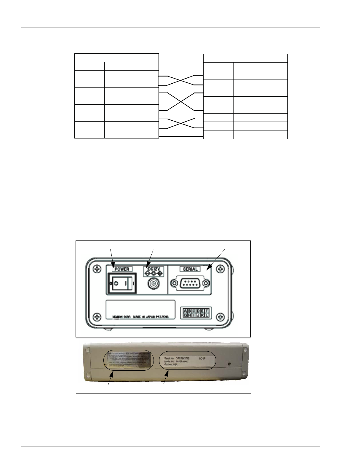
the unit. Following is the connection diagram.
MDE-4507 Magnetic Card Encoder User’s Manual · June 2006 Page 2-1
Page 8
Installing MCE Communication Connections
D-sub-9S (female)
Pin No. Signal
2 RD (RxD)
3 SD (TxD)
4 ER (DTR)
5 SG (GND)
6 DR (DSR)
7 RS (RTS)
8 CS (CTS)
Shield FG
Communication Connections
MCE requires the use of a PC for operation. The type of PC used can vary according to the
application and optional printer(s) that may be connected.
Only the authorized Gasboy model encoder hardware, purchased from Gasboy, will work with
this MCE software.
Figure 2-1: Back Panel and Side View of MCE
D-sub-9S (female)
Pin No. Signal
2 RD (RxD)
3 SD (TxD)
4 ER (DTR)
5 SG (GND)
6 DR (DSR)
7 RS (RTS)
8 CS (CTS)
Shield FG
Power Switch
FCC Label
• Power switch: Power on/off the unit.
• DC Jack: Connect the AC adapter supplied with the unit.
• RS-232 Connector: Connect to Host/PC with the interface cable supplied with the unit.
DC Jack
Model number & Serial number
RS-232 Connector
Note: Turn the power off before connecting the interface cable to the unit.
Page 2-2 MDE-4507 Magnetic Card Encoder User’s Manual · June 2006
Page 9

Installing MCE Software Installing MCE
Installing MCE Software
To install the Gasboy MCE software, proceed as follows:
1 Insert the Gasboy MCE for Windows software CD in to your CD-ROM drive. The “Gasboy
MCE for Windows” window appears (Figure 2-2).
Note: It may take 30 to 120 seconds for the Gasboy MCE for Windows screen to appear.
Figure 2-2: Gasboy MCE for Windows Installation
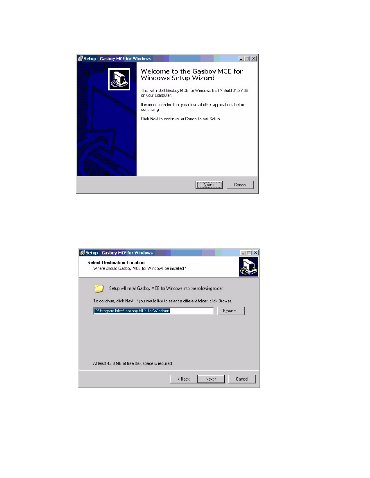
2 Click Install. The “Welcome to the Gasboy MCE for Windows Setup Wizard” window
appears (Figure 2-3 on page 2-4).
MDE-4507 Magnetic Card Encoder User’s Manual · June 2006 Page 2-3
Page 10
Installing MCE Installing MCE Software
Figure 2-3: Gasboy MCE for Windows Setup Wizard
3 Click Next. The “Select Destination Location” window appears (Figure 2-4).
Note: To cancel the installation at any time, click Cancel and then Yes.
Figure 2-4: Select Destination Location
Page 2-4 MDE-4507 Magnetic Card Encoder User’s Manual · June 2006
Page 11
Installing MCE Software Installing MCE
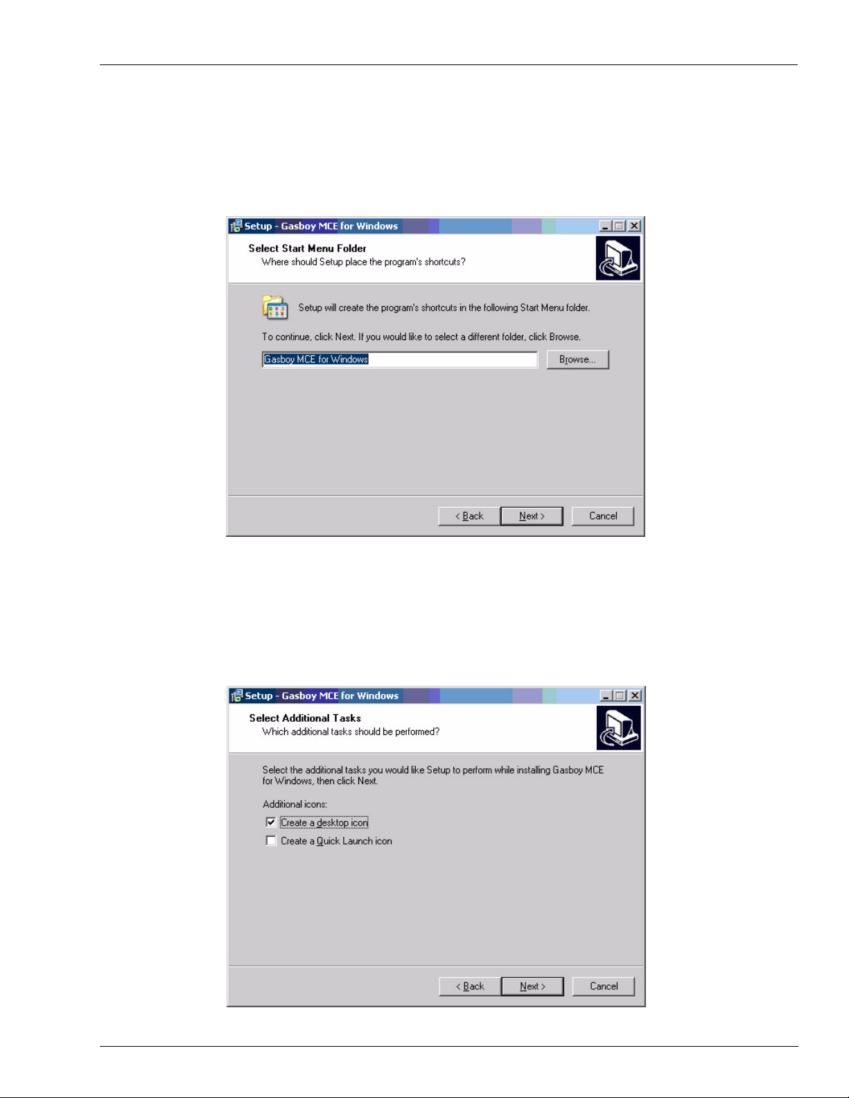
4 Type a destination folder or select a destination folder by clicking Browse, or accept the
displayed destination folder and click Next. The “Select Start Menu Folder” window appears
(Figure 2-5).
Figure 2-5: Select Start Menu Folder
5 Type an appropriate shortcut name for the program or select one by clicking Browse, or accept
the shortcut name shown and click Next. The “Select Additional Tasks” window appears
(Figure 2-6).
Figure 2-6: Select Additional Tasks
MDE-4507 Magnetic Card Encoder User’s Manual · June 2006 Page 2-5
Page 12
Installing MCE Installing MCE Software
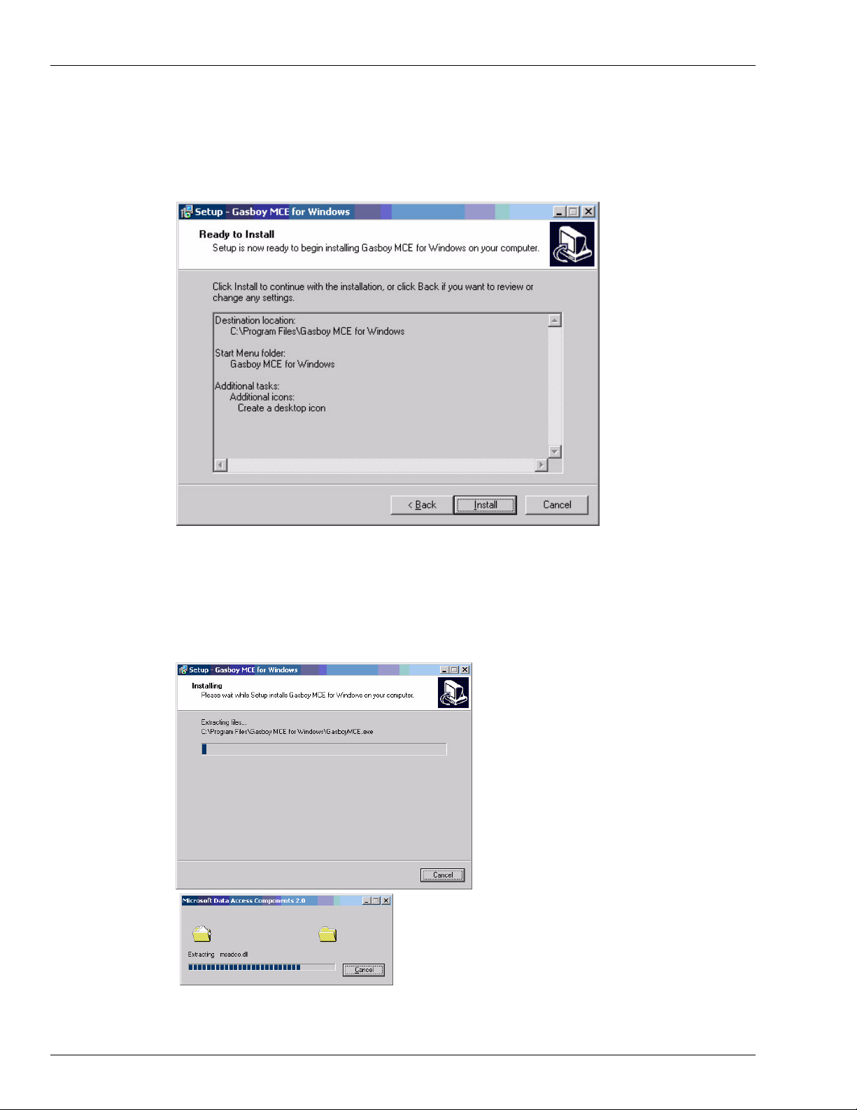
6 Under Additional icons, select the optional additional tasks option and click Next. The “Ready
to Install” window appears (Figure 2-7).
Figure 2-7: Ready to Install
Verify settings. Click Back to change settings
7 Click Install. The “Installing” window appears (Figure 2-8).
Figure 2-8: Installing
Page 2-6 MDE-4507 Magnetic Card Encoder User’s Manual · June 2006
Page 13
Uninstalling MCE Software Installing MCE
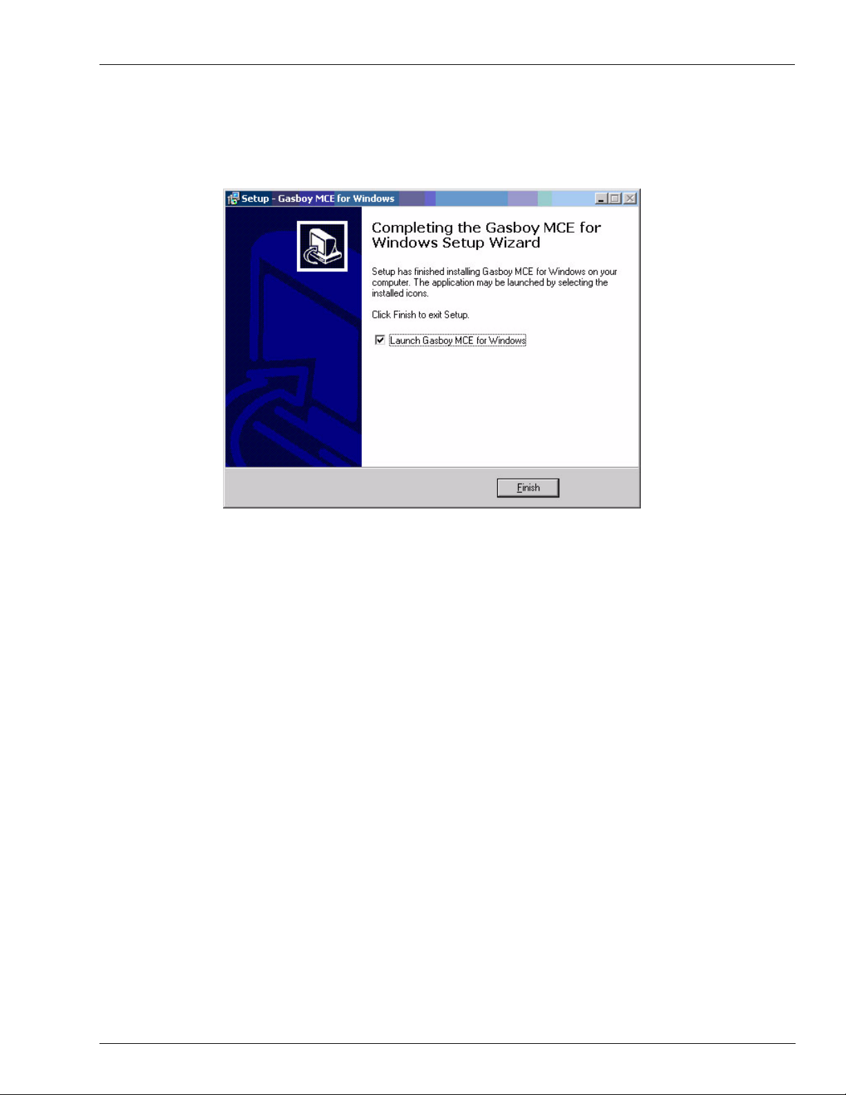
8 When the installation is complete, the “Completing the Gasboy MCE for Windows Setup
Wizard” window appears (Figure 2-9).
Figure 2-9: Completing the Gasboy MCE for Windows Setup Wizard
9 Select the “Launch Gasboy MCE for Windows” check box to display the MCE login screen
(Figure 4-1), or leave it blank to end this installation without displaying the login screen. The
application can be started anytime by selecting the icons or the program listing. Click Finish
(Figure 2-9).
Uninstalling MCE Software
You can uninstall the Gasboy MCE software using one of the following methods:
• Method 1:
From the desktop, select Start>Programs>Uninstall Gasboy MCE for Windows.
• Method 2:
1 From the Start menu, select Settings-Control Panel. The Control Panel window
appears.
2 Double click Add/Remove Programs. The Add/Remove Programs window appears.
3 Select Gasboy MCE for Windows and click Remove. MCE software is uninstalled.
MDE-4507 Magnetic Card Encoder User’s Manual · June 2006 Page 2-7
Page 14

Installing MCE Uninstalling MCE Software
This page is intentionally left blank.
Page 2-8 MDE-4507 Magnetic Card Encoder User’s Manual · June 2006
Page 15

Communication Port Connecting to MCE
3 – Connecting to MCE
Communication Port
Gasboy MCE has one asynchronous communication port for connecting RS232 to a PC. The
connection should be made with the supplied cable. If the cable needs to be extended, the
overall cable length is limited to 50 feet. See “Installing MCE” on page 2-1 for specific
installation connections.
The serial port is used for connecting a PC. All commands to the encoder are processed
through this port. Refer to “Configuring COM Port Settings” on page 8-2 to program which
PC COM port the encoder is to be connected to.
Printer(s)
Hard-copy Printer - This is an optional printer used to provide hard-copy printouts. This
device should be connected to the PC parallel port, if used.
Note: The printer should be UL listed and should not be used over a hazardous location.
MDE-4507 Magnetic Card Encoder User’s Manual · June 2006 Page 3-1
Page 16

Connecting to MCE Printer(s)
This page is intentionally left blank.
Page 3-2 MDE-4507 Magnetic Card Encoder User’s Manual · June 2006
Page 17

Logging On Working with MCE
4 – Working with MCE
Logging On
Once the software has been installed, perform the following:
1 Double click the Gasboy MCE software icon. The Gasboy Login window appears.
2 Enter the login password and click OK (Figure 4-1). The Gasboy Card Encoder window
appears (Figure 4-2 on page 4-2).
Note: The initial password for logging in is “gasboy” (case-sensitive). You can change this
password, after logging on the first time. If you forget your password, you can use a
specially provided code card that changes the password back to “gasboy”.
Figure 4-1: Gasboy Login Window
MDE-4507 Magnetic Card Encoder User’s Manual · June 2006 Page 4-1
Page 18

Working with MCE Creating a Card Layout
Creating a Card Layout
This version of the software allows the creation of only one card and PIN layout configuration
at a time. To navigate to the MCE Card Layout window, proceed as follows:
1 Click File>Create New Card Layout >Card Layout (Figure 4-2). The Gasboy Card Encoder
- Create New Card Layout window appears (Figure 4-3).
Figure 4-2: Gasboy Card Encoder Screen
Figure 4-3: Gasboy Card Encoder - (Create New Card Layout)
Page 4-2 MDE-4507 Magnetic Card Encoder User’s Manual · June 2006
Page 19

Creating a Card Layout Working with MCE
At the top of the form (Figure 4-3 on page 4-2), you will notice the Company Name, Card
Layout, and PIN Layout fields (Figure 4-4). You may enter the values directly into these
fields, but it is recommended that you use wizard fields and controls to create your layout. The
details of wizard fields and buttons are provided in the following pages. To save layouts, click
Save & Load. A series of message windows will appear explaining that any cards will be
removed from the system and new layouts will be saved. Click Yes and OK to save your
layouts.
PIN Layout
This version allows the creation of only one card and PIN layout. Your MCE can calculate
non-Cenex PINs and print the PINs used on Gasboy CFN and Series 1000 Systems. Cenex
PIN generation is currently not a function of this software. PINs can be calculated only against
numeric data on the card. You cannot calculate a PIN against A, C, E, or a field separator. If
PINs are desired, the following data must be loaded.
PIN LAYOUT
The PIN layout is used to determine which card characters are used for calculation of the PIN.
P
Calculation character - Indicates that the associated card layout character is used for the PIN
calculation. Only numeric characters should be indicated for the PIN calculation. No more
than 20 characters can be designated for PIN calculation.
X
Non-calculation character - Indicates that the associated card layout character is not used for
the PIN calculation.
PIN KEY
The PIN key for your site should be loaded for proper PIN calculation.
Note: PINs are not printed for cards where a READ ERROR has occurred.
Note: The wizard fields and buttons are arranged vertically from top to bottom (F igure 4-3 on
page 4-2).
Figure 4-4: Gasboy Card Encoder - Company Name, Card and PIN Layout Fields
MDE-4507 Magnetic Card Encoder User’s Manual · June 2006 Page 4-3
Page 20

Working with MCE Creating a Card Layout
Personal Identification Number (PIN) Key Field
In this field, enter the PIN Key assigned to your site (Figure 4-5).
Figure 4-5: PIN Key
Entering Constant Fields
Constant fields are typically used for system ID, or any field that remains the same on each
card. Constants can be 0-9, A, C, E.
To enter a constant field into the card layout, proceed as follows:
1 Enter the number (for example - 7559) in the Constants box (Figure 4-6).
2 To include the constant in the PIN Layout, select the Include in PIN Layout checkbox.
Note: The software uses this constant in the PIN calculation for each card, if this checkbox is
selected. System ID should not be included in the PIN calculation.
3 Click Insert Constant Field. The Card Layout and PIN Layout fields are automatically
updated.
Note: You may enter constants at any time. For exa mple, enteri ng an ex piration date after the
sequential fields.
Figure 4-6: Gasboy Card Encoder - Updated Card and PIN Layout Fields
Page 4-4 MDE-4507 Magnetic Card Encoder User’s Manual · June 2006
Page 21

Creating a Card Layout Working with MCE
Inserting Field Separators
Constant field separator “-” (hyphen) is used when a field separator needs to appear on the
card.
Click Insert Field Separator (Figure 4-7) to update the Card Layout and PIN Layout fields
(Figure 4-8).
Figure 4-7: Constant Field Separator
Figure 4-8: Card Layout and PIN Layout Fields with Field Separator
Note: The software automatically places a space between the fields entered via the buttons.
This space is not encoded on the card. If you enter the values directly, you must insert a
space between the fields.
Inserting First Sequential Number
The MCE software allows you to add up to three different sequential number fields to the card
layout.
A sequential number up to 10 digits can be added to the layout. The number can be in an
incrementing or decrementing order. To add the first sequential number to the card layout,
enter the number of characters, starting number, and select the increment or decrement type.
Select the Include in PIN Layout check box, if applicable. The program keeps track of the
last sequential number that was loaded into the card data file. If you are entering the value
directly, "I" should always be used as the first sequential field.
Click Insert 1st Sequential Field (Figure 4-9). The Card Layout and PIN Layout fields are
updated (Figure 4-10 on page 4-6).
Figure 4-9: First Sequential Number
MDE-4507 Magnetic Card Encoder User’s Manual · June 2006 Page 4-5
Page 22

Working with MCE Creating a Card Layout
Figure 4-10: Card Layout and PIN Layout Fields with First Sequential Number
Inserting Second Sequential Number
This is the same setup as the first sequential number except that it is for a second independent
sequential number. "S" should always be used as the second sequential field, if you are
entering the values directly.
Inserting Third Sequential Number
This is same setup as the first sequential number except that it is for a third independent
sequential number. "T" should always be used as the third sequential field, if you are entering
the values directly .
Figure 4-11: Layout Containing First, Second, and Third Sequential Numbers
Page 4-6 MDE-4507 Magnetic Card Encoder User’s Manual · June 2006
Page 23

Creating a Card Layout Working with MCE
Inserting Variable Fields
This field is used when the actual card data that is loaded varies from one card to the next. "X"
should always be used as a variable character, if you are entering the values directly.
To insert a variable fiel d, proceed as follows:
1 Enter the character length of your variable field (Figure 4-12), and select the Include in PIN
Layout checkbox, if applicable.
2 Click Insert Variable Field to update your Card Layout and PIN Layout fields (Figure 4-13).
Figure 4-12: Variable Field
Figure 4-13: Card Layout and PIN Layout Fields with Variable
To enter an additional variable field, replace the values in the Variable Field boxes (Figure 4-
14), and click Insert Variable Field (Figure 4-15). The Card Layout and PIN Layout fields
are updated with the additional variable.
Figure 4-14: Additional Variable Field
Figure 4-15: Card Layout and PIN Layout Fields with Additional Variable
MDE-4507 Magnetic Card Encoder User’s Manual · June 2006 Page 4-7
Page 24

Working with MCE Loading a Card Layout
Spaces, Start Sentinels, and Additional Field Separat ors
As in the case of Field Separators, Spaces and Start Sentinels may be inserted where
appropriate (Figure 4-16).
The program automatically inserts spaces between fields to aid in differentiation between the
various card fields. Spaces are not encoded on the cards.
The letter "B" is used to identify an additional Start Sentinel as shown below in the example.
B 7559 IIIIII
The program automatically inserts the first Start Sentinel.
Figure 4-16: Space and Start Sentinel
Loading a Card Layout
There are two ways to load a card layout:
• Click File>Load/Edit Card Layout and select the type of layout (Figure 4-17 an d Figure
4-18 on page 4-9). You should load a card layout each time you start the application, or
change the layout.
• Click Save & Load on the Gasboy Card Encoder - (Create New Card Layout) screen
(Figure 4-3). This function also allows you to create a card file. After you click Save &
Load, you have a Yes/No option to delete all previously entered information in the Card
File or preserve the Card File.
Only the authorized Gasboy model encoder hardware, purchased from Gasboy, will work with
this MCE software. This Gasboy encoder must also be connected to your PC, powered on, and
the correct communications port number must be selected in the MCE software before PINs
can be displayed or created.
Figure 4-17: Load Card Layout Button
Page 4-8 MDE-4507 Magnetic Card Encoder User’s Manual · June 2006
Page 25

Printing a Card Layout Working with MCE
Figure 4-18: Load/Edit Card Layout
Printing a Card Layout
On the Gasboy Card Encoder - [Load/Edit Card Layout], click Print Card Layout. Card and
PIN Layout with PIN Key print to the parallel printers.
MDE-4507 Magnetic Card Encoder User’s Manual · June 2006 Page 4-9
Page 26

Working with MCE Creating a Card File
Creating a Card File
After you have created and saved a new layout, you should create a Card File.
IMPORTANT INFORMATION
This erases all previously entered information in the Card File. Therefore, unless you plan
to start over with a new card file, you should not use this feature.
1 To create a new card file, click File>Create New Card File (Figure 4-19). A message window
appears to confirm if you want to create a new card file (Figure 4-20).
Figure 4-19: Gasboy Card Encoder - Create New Card File Option
Figure 4-20: Create New Card File Dialog Box
Click Yes. All previous records are erased and the following dialog box appears.
2
Note: If you click No, a new card file will not be created.
Figure 4-21: New Card File Created Dialog Box
3
Click OK.
Note: You can also create a card file during the process of creating your layout, see section
“Loading a Card Layout” on page 4-8.
Page 4-10 MDE-4507 Magnetic Card Encoder User’s Manual · June 2006
Page 27

Creating a Card File Working with MCE
Editing Your Card File
To edit data that is to be encoded on your card, click Edit > Card File (Figure 4-22).
Only the authorized Gasboy model encoder hardware, purchased from Gasboy, will work with
this MCE software. This Gasboy encoder must also be connected to your PC, powered on, and
the correct communications port number must be selected in the MCE software before PINs
can be displayed or created.
Figure 4-22: Gasboy Card Encoder - Edit
MDE-4507 Magnetic Card Encoder User’s Manual · June 2006 Page 4-11
Page 28

Working with MCE Adding Cards to your Card File
Adding Cards to your Card File
Enter your variable fields in the blank fields above the card file, and click Add to Card File
(Figure 4-23). Your card and PIN will be listed on the Card File box.
Figure 4-23: Gasboy Card Encoder - (Card File)
Encoding Cards
From the Card File list, select the card(s) that needs to be encoded and click Encode Card(s)
(Figure 4-23). To select a range of cards, press the Ctrl key and select the cards using the
mouse (Figure 4-24), then click Encode Card(s). If you are encoding all cards in the file, click
Encode Card(s) without selecting or highlighting any card(s).
Figure 4-24: Gasboy Card Encoder - (Card File)
Page 4-12 MDE-4507 Magnetic Card Encoder User’s Manual · June 2006
Page 29

Reading Cards in Layout Mode Working with MCE
Printing Card File
On the Gasboy Card Encoder - (Card File), click Print Card File. This function prints all
cards and their PINs directly to the printer.
Reading Cards in Layout Mode
Click Edit>Read Card(Layout Mode). This allows you to read cards using the layout loaded.
It also displays the PIN for the cards read, if the PIN is required.
Notes:1) To read cards in the layout mode, a card layout must be loaded.
2) Only the authorized Gasboy model encoder hardware, purchased from Gasboy, will
work with this MCE software. This Gasboy encoder must also be connected to your
PC, powered on, and the correct communications port number must be selected in the
MCE software before PINs can be displayed.
MDE-4507 Magnetic Card Encoder User’s Manual · June 2006 Page 4-13
Page 30

Working with MCE Reading Cards in Layout Mode
This page is intentionally left blank.
Page 4-14 MDE-4507 Magnetic Card Encoder User’s Manual · June 2006
Page 31

Writing Cards in Raw Mode Writing and Reading Cards in Raw Mode
5 – Writing and Reading Cards in Raw Mode
Writing Cards in Raw Mode
This option can be used to encode card data irrespective of the layout that is presently loaded
into the software configuration. Any card size (up to 37 characters) can be loaded by entering
the data on the keyboard. This mode does not generate tables, cards or PINs.
1 Click Edit>Raw Write Mode.
2 Enter data to be encoded on the card.
3 Click Write. When a card is inserted into the encoder, it is encoded with the data that you have
entered. If the card was not blank, the existing data is overwritten.
Reading Cards in Raw Mode
This option can be used to read card data irrespective of the layout that is presently loaded into
the software configuration. This mode displays the data read from the card as a string of
characters and does not display the PIN.
1 Click Edit>Raw Read Mode. The Raw Read Mode screen appears.
2 Click Read. When a card is inserted, the data read from the card is displayed.
MDE-4507 Magnetic Card Encoder User’s Manual · June 2006 Page 5-1
Page 32

Writing and Reading Cards in Raw Mode Reading Cards in Raw Mode
This page is intentionally left blank.
Page 5-2 MDE-4507 Magnetic Card Encoder User’s Manual · June 2006
Page 33

Characteristics Specifications
6 – Specifications
Characteristics
This MCE software will only function on PCs running Windows XP Professional.
Dimensions 11" L x 4.6" W x 2.2" H
Weight Approximately 2.0 Kg (without AC adapter and cable).
Power
Requirements
Environmental
Requirements
Approvals EMC
Communication One Asynchronous port, RS-232 compatible
Baud Rate 9600
Encoder Write/Read Function: ABA Track 2
MCE: 115-230 VAC
• Operating: 0
Unit should be located in a clean office-type environment for maximum life.
• Storage: -20
There should be no functional failure after 12 hours from
returning to standard conditions.
Start Bit: 1 Stop Bit: 1
Data: 8 Parity: Even
Transport Mechanism: Motorized Forward and Reverse Control
Life: 500,000 passes
±10%, 47-63 HZ, 50 watts maximum
°
to 50°C, 20% to 80% R.H. (Non-condensing)
°
to 70°C, 20% to 80% R.H.
MDE-4507 Magnetic Card Encoder User’s Manual · June 2006 Page 6-1
Page 34

Specifications Characteristics
This page is intentionally left blank.
Page 6-2 MDE-4507 Magnetic Card Encoder User’s Manual · June 2006
Page 35

7 – Preventive Maintenance
The magnetic heads of the MCE reader should be cleaned every 1000 passes or six months,
whichever occurs first. Proper and regular cleaning of the magnetic heads helps to ensure
longer life of your unit.
Cleaning cards are available from Gasboy and sold in lots of 50 (P/N Q11482-01 is one box of
50 cards). Each card is saturated in cleaning fluid and individually wrapped.
To clean the reader, log in to MCE and do the following:
1 Select Raw Read Mode from the Edit menu (refer to “Writing and Reading Cards in Raw
Mode” on page 5-1) and click Read.
2 Enter the cleaning card into the reader with the rough wet side of the card turned up.
The unit sends the card through the reader as any other mag card and display an error message.
Preventive Maintenance
3 Repeat step 2 several times.
4 Throw away the cleaning card.
MDE-4507 Magnetic Card Encoder User’s Manual · June 2006 Page 7-1
Page 36

Preventive Maintenance
This page is intentionally left blank.
Page 7-2 MDE-4507 Magnetic Card Encoder User’s Manual · June 2006
Page 37

Changing the Password Other Options
8 – Other Options
Changing the Password
You can change the MCE password using one of the following methods:
Method 1
1 On the main screen, click Options>Change Password. The Change Login Password dialog
box appears.
Figure 8-1: Change Login Password Dialog Box
Enter the new password twice in the fields provided in the dialog box, and click OK.
2
Note: The length of the password should be between one and ten characters. You can use
numbers, upper and lower case letters, and special characters.
Note: If you enter more than ten characters and attempt to save the password, the following
message appears.
Figure 8-2: Invalid Password Message
MDE-4507 Magnetic Card Encoder User’s Manual · June 2006 Page 8-1
Page 38

Other Options Configuring COM Port Settings
Method 2 - To change the Password to the Default
1 Open the Login screen. Click Read Code Card. The Code Card Login screen appears.
Figure 8-3: Code Card Login Screen
2
Select the Comm Port list and click Open.
3 Click Read.
4 Insert Code Card into the MCE. A message appears indicating that your password has been
successfully changed to "gasboy".
Configuring COM Port Settings
This option allows you to set the COM Port that the encoder is connected to. Select the
appropriate COM Port and click OK. The setting is maintained when you log out of MCE.
Accessing Online Help
From the Gasboy Card Encoder Main screen, select Help - Help with Gasboy Card Encoder.
The online version of MDE-4507 MCE User Manual appears.
Page 8-2 MDE-4507 Magnetic Card Encoder User’s Manual · June 2006
Page 39

Configuring COM Port Settings Other Options
Accessing “About Gasboy Card Encoder” Details
1 From the Gasboy Card Encoder Main screen, select Help - About Gasboy Card Encoder.
The About Gasboy Card Encoder dialog box appears, displaying the MCE version and the
Database Version.
2 To access System Information, click System Information. The System Information dialog
box appears, displaying the current system's information.
About MCE Status Messages
Tabulate d below are some Encoder status messages (Figure 8-4), their description and
suggested user action for each message that appears on the Code Card Login screen.
Figure 8-4: Encoder Messages
Message Description/ Suggested User Action
Read or Write Ok Successfully read or write to the card.
No response
Reset action failed
CTS control line was turned off Power off on the Encoder Hardware.
VRC error Defective magnetic card. Try another card.
STC error Card was placed into the Encoder incorrectly. Try
MDE-4507 Magnetic Card Encoder User’s Manual · June 2006 Page 8-3
Power off on the Encoder Hardware.
Or
Serial connector disconnected.
Or
Serial connector disconnected.
again with the same card inserted with the
magnetic strip in the correct position.
Page 40

Other Options Configuring COM Port Settings
This page is intentionally left blank.
Page 8-4 MDE-4507 Magnetic Card Encoder User’s Manual · June 2006
Page 41

Index
Index
A
Accessing Online Help 8-2
Adding Cards to your Card File 4-12
C
Card 4-3
Card Layout Field 4-3
Characteristics 6-1
Configuring COM Port Settings 8-2
Constant 4-5
Constant field 4-4
seperator 4-5
Creating a Card File 4-10
Creating a Card Layout 4-2
E
Editing Your Card File 4-11
Encoding Cards 4-12
F
First Sequential Number 4-5
G
Gasboy Card Encoder 8-3
R
Raw Mode 5-1
S
Second Sequential Number 4-6
Spaces and Start Sentinels 4-8
Spaces, Start Sentinels, and Additional
Field Separators 4-8
Specifications 6-1
T
Third Sequential Number 4-6
V
Variable field 4-7
variable field
Additional variable 4-7
W
wizard fields 4-3
Writing and Reading Cards in Raw
Mode 5-1
Writing Cards 5-1
I
Inserting Field Separators 4-5
L
Loading a Card Layout 4-8
M
MCE 8-3
MCE Status Messages 8-3
O
Options 8-1
P
Password 8-1
Personal Identification Number (PIN)
Key Field 4-4
PIN 4-4
PIN Layout 4-4
check box 4-4
PIN Layout field 4-3
Preventive Maintenance 7-1
Printing a Card Layout 4-9
MDE-4507 Magnetic Card Encoder User’s Manual · June 2006 Index-1
Page 42

Index
© 2006 GASBOY
7300 West Friendly Avenue • Post Office Box 22087
Greensboro, North Carolina 27420
Phone 1-800-444-5529 • http://www.gasboy.com • Printed in the U.S.A.
MDE-4507 Magnetic Card Encoder User’s Manual · June 2006
 Loading...