

Page 1

Introduction
Purpose
This manual provides instructions to install the Boot Switch Kit (M14142K001) in Gasboy®
9800A/2600A/215A/7215A front-load model dispensers.
Table of Contents
Topic Page
Introduction 1
Important Safety Information 3
Installing Boot Switch Kit (M14142K001) 5
MDE-5163A
Boot Switch Kit (M14142K001)
Installation Instructions
August 2014
Required Tools and Materials
Following tools and materials are required to install the Boot Switch Kit:
•Nut Driver
•Heat Gun
• Thread Lock
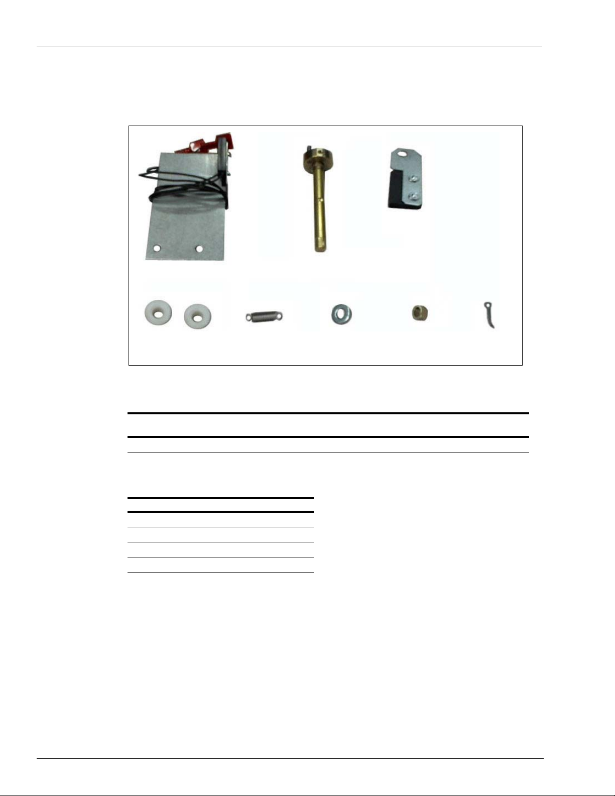
Parts List
Following table lists parts included in the Boot Switch Kit:
Item Description Part Number Quantity
1 Extension Spring 064400 1
2 Nozzle Boot Bearing 064401 2
3 Nozzle Bracket Lock Bushing M14068B001 1
4 Flat Washer (Spacer) K65235-33 1
5 Cotter Pin K02124 1
6 Reed Switch and Bracket Assembly M14143A001 1
7 Lever Shaft Assembly M14144A001 1
8 Magnet and Bracket Assembly M14145A001 1
MDE-5163A Boot Switch Kit (M14142K001) Installation Instructions · August 2014 Page 1
Page 2
IntroductionIntroduction
(i)
Reed Switch and Bracket
Assembly (M14143A001)
(ii)
Lever Shaft Assembly
(M14144A001)
(iii)
Magnet and Bracket
Assembly (M14145A001)
(v)
Extension Spring
(064400)
(vii)
Nozzle Bracket Lock
Bushing (M14068B001)
(viii)
Cotter Pin
(K02124)
(iv)
Nozzle Boot Bearing
(064401)
(vi)
Flat Washer
(K65235-33)
Figure 1 shows the components in the Boot Switch Kit.
Figure 1: Boot Switch Kit Components
Related Documents
Document
Number Title GOLD
MDE-4430 Important Warnings and Safeguards Gasboy
Abbreviations and Acronyms
Term Description
ATC Automatic Temperature Compensation
®
GOLD Gilbarco
I.S Intrinsic Safety
OEM Original Equipment Manufacturer
Online Documentation
SM
Library
®
Safety and Warranty Docs
Page 2 MDE-5163A Boot Switch Kit (M14142K001) Installation Instructions · August 2014
Page 3
Important Safety Information
The EMERGENCY STOP, ALL STOP, and
PUMP STOP buttons at the cashier’s station
WILL NOT shut off electrical power to the
pump/dispenser. This means that even if you
activate these stops, fuel may continue to flow
uncontrolled.
You must use the TOTAL ELECTRICAL
SHUT-OFF in the case of an emergency and not
the console’s ALL STOP and PUMP STOP or
similar keys.
!
WARNING
!
Notes: 1) Save this Important Safety Information section
in a readily accessible location.
2) Although DEF is non-flammable, Diesel is
flammable. Therefore, for DEF cabinets that are
attached to Diesel dispensers, follow all the
notes in this section that pertain to flammable
fuels.
This section introduces the hazards and safety precautions
associated with installing, inspecting, maintaining or servicing
this product. Before performing any task on this product, read
this safety information and the applicable sections in this
manual, where additional hazards and safety precautions for
your task will be found. Fire, explosion, electrical shock or
pressure release could occur and cause death or serious injury,
if these safe service procedures are not followed.
Preliminary Precautions
You are working in a potent ially dangerous environment of
flammable fuels, vapors, and high voltage or pressures. Only
trained or authorized individuals knowledgeable in the related
procedures should install, inspect, maintain or service this
equipment.
Emergency Total Electrical Shut-Off
The first and most important information you must know is how
to stop all fuel flow to the pump/dispenser and island. Loca te
the switch or circuit breakers that shut of f all p ower to all fueling
equipment, dispensing devices, and Submerged Turbine
Pumps (STPs).
Important Safety Information
Read the Manual
Read, understand and follow this manual and any other labels
or related materials supplied with this equipment. If you do not
understand a procedure, call a Gasboy Authorized Service
Contractor or call the Gasboy Service Center at
1-800-444-5529. It is imperative to your safety and the safety of
others to understand the procedures before beginning work.
Follow the Regulations
Applicable information is available in National Fire Protection
Association (NFPA) 30A; Code for Motor Fuel Dispensing
Facilities and Repair Garages, NFPA 70; National Electrical
Code (NEC), Occupational Safety and Health Administration
(OSHA) regulations and federal, state, and local codes. All
these regulations must be followed. Failure to install, inspect,
maintain or service this equipment in accordance with these
codes, regulations and standards may lead to legal citations
with penalties or affect the safe use and operation of the
equipment.
Replacement Parts
Use only genuine Gasboy replacement parts and retrofit kits on
your pump/dispenser. Using parts other than genuine Gasboy
replacement parts could create a safety hazard and violate
local regulations.
Safety Symbols and Warning Words
This section provides important information about wa rning
symbols and boxes.
Alert Symbol
Total Electrical Shut-Off Before Access
Any procedure that requires access to electrical co mponent s or
the electronics of the dispenser requires total electrical shut off
of that unit. Understand the function and location of this swit ch
or circuit breaker before inspecting, installing, maintaining, or
servicing Gasboy equipment.
Evacuating, Barricading and Shutting Off
Any procedure that requires access to the pump/dispenser or
STPs requires the following actions:
• An evacuation of all unauthorized persons and vehicles
from the work area
• Use of safety tape, cones or barricades at the affected
unit(s)
• A total electrical shut-off of the affe cted unit(s)
MDE-5163A Boot Switch Kit (M14142K001) Installation Instructions · August 2014 Page 3
This safety alert symbol is used in this manual and on
warning labels to alert you to a precaution which must be
followed to prevent potential personal safety hazards. Obey
safety directives that follow this symbol to avoid possible injury
or death.
Signal Words
These signal words used in this manual and on warning labels
tell you the seriousness of particular safety hazards. The
precautions below must be followed to prevent death, injury or
damage to the equipment:
DANGER: Alerts you to a hazard or unsafe practice
!
which will result in death or serious injury.
WARNING: Alerts you to a hazard or unsafe practice
!
that could result in death or serious injury.
CAUTION with Alert symbol: Designates a hazard or
!
unsafe practice which may result in minor injury.
CAUTION without Alert symbol: Designates a hazard
or unsafe practice which may result in property or
equipment damage.
Working With Fuels and Electrical Energy
Prevent Explosions and Fires
Fuels and their vapors will explode or burn, if ignited. Spilled or
leaking fuels cause vapors. Even filling customer tanks will
cause potentially dangerous vapors in the vicinity of the
dispenser or island.
DEF is non-flammable. Therefore, explosion and fire safety
warnings do not apply to DEF lines.
Page 4

Important Safety InformationImportant Safety Information
The pump/dispenser contains a chemical known to the
State of California to cause cancer.
WARNING
!
The pump/dispenser contains a chemical known to the
State of California to ca use birth defects or other
reproductive harm.
WARNING
!
Gasoline/DEF ingested may cause
unconsciousness and burns to internal organs.
Do not induce vomiting. Keep airway open.
Oxygen may be needed at scene. Seek medical
advice immediately.
WARNING
!
WARNING
!
DEF generates ammonia gas at higher temperatures.
When opening enclosed panels, allow the unit to air out to
avoid breathing vapors.
If respiratory difficulties develop, move victim away from
source of exposure and into fresh air. If symptoms persist,
seek medical attention.
Gasoline/DEF spilled in eyes may cause burns to
eye tissue. Irrigate eyes with water for
approximately 15 minutes. Seek medical advice
immediately.
WARNING
!
WARNING
!
Gasoline inhaled may cause unconsciousness
and burns to lips, mouth and lungs. Keep airway
open. Seek medical advice immediately.
WARNING
!
Gasoline spilled on skin may cause burns.
Wash area thoroughly with clear water.
Seek medical advice immediately.
WARNING
!
DEF is mildly corrosive. Avoid contact with eyes, skin, and
clothing. Ensure that eyewash stations and safety s howers
are close to the work location. Seek medical advice
recommended treatment if DEF spills into eyes.
WARNING
!
No Open Fire
Open flames from matches, lighters, welding torches
or other sources can ignite fuels and their vapors.
No Sparks - No Smoking
Sparks from starting vehicles, starting or using pow er tools,
burning cigarettes, cigars or pipes can also ignite fuels and
their vapors. Static electricity, including an electrostatic charge
on your body, can cause a spark suff icien t to ign ite fuel vap ors .
Every time you get out of a vehicle, touch the metal of your
vehicle, to discharge any electrostatic charge before you
approach the dispenser island.
Working Alone
It is highly recommended that someone who is capable of
rendering first aid be present during servicing. Familiarize
yourself with Cardiopulmonary Resuscitation (CPR) methods, if
you work with or around high voltages. This information is
available from the American Red Cross. Always advise the
station personnel about where you will be working, and caution
them not to activate power while you are working on the
equipment. Use the OSHA Lockout/Tagout procedures. If you
are not familiar with this requirement, refer to this information in
the service manual and OSHA documentation.
In an Emergency
Inform Emergency Personnel
Compile the following information and inform emergency
personnel:
• Location of accident (for example, address, front/back of
building, and so on)
• Nature of accident (for example, possible heart attack, run
over by car , burns, and so on)
• Age of victim (for example, baby, teenager, middle-age,
elderly)
• Whether or not victim has received first aid (for example,
stopped bleeding by pressure, and so on)
• Whether or not a victim has vomited (for example, if
swallowed or inhaled something, and so on)
Working With Electricity Safely
Ensure that you use safe and established practices in working
with electrical devices. Poorly wired devices may cause a fire,
explosion or electrical shock. Ensure that grounding
connections are properly made. Take care that sealing devices
and compounds are in place. Ensure that you do not pinch
wires when replacing covers. Follow OSHA Lockout/Tagout
requirements. Station employees and service contractors need
to understand and comply with this progra m completely to
ensure safety while the equipment is down.
Hazardous Materials
Some materials present inside electronic enclosures may
present a health hazard if not handled correctly. Ensure that
you clean hands after handling equipment. Do not place any
equipment in the mouth.
Page 4 MDE-5163A Boot Switch Kit (M14142K001) Installation Instructions · August 2014
IMPORTANT: Oxygen may be needed at scene if gasoline has
been ingested or inhaled. Seek medical advice immediately.
Lockout/Tagout
Lockout/Tagout covers servicing and maintena nce of machines
and equipment in which the unexpected energization or startup of the machine(s) or equipment or release of stored energy
could cause injury to employees or personnel. Lockout/Tagout
applies to all mechanical, hydraulic, chemical or other energy,
but does not cover electrical hazards. Subpart S of 29 CFR Part
1910 - Electrical Hazards, 29 CFR Part 1910.333 contains
specific Lockout/Tagout provision for electrical hazards.
Page 5

Installing Boot Switch Kit (M14142K001)
Do not dispose of or incinerate the mercury switch.
Return the entire switch unit for recycling to:
Power Components
56641 Twin Branch Drive
Mishawaka, IN 56545
!
E-ring
Installing Boot Switch Kit (M14142K001)
Before installing, read and understand the warnings and safeguard precautions for the remote
dispensers and pumps provided in MDE-4430 Important Warnings and Safeguards.
Removing Mercury Switch
Note: Mercury switch that may be currently installed in the pump/dispenser is no longer
available from the Original Equipment Manufacturer (OEM) supplier (environmental
concerns).
Figure 2: Mercury Switch Configuration (No Longer Available)
The current kit uses a magnet/reed switch combination. The magnet/reed switch is
preassembled but it requires some further assembly.
Note: The magnet/reed switch is not as compact as the mercury switch,
on the right side of the boot instead of the left side where the mercury switch is located.
MDE-5163A Boot Switch Kit (M14142K001) Installation Instructions · August 2014 Page 5
so it has to be placed
Page 6

Installing Boot Switch Kit (M14142K001)Installing Boot Switch Kit (M14142K001)
Lift the handle to
remove the set screw.
To remove the mercury switch, proceed as follows:
1 Remove the door from the pump/dispenser.
2 Disconnect the wire plugs (fastons) that connect the mercury switch to the Intrinsic Safety
(I.S) barrier.
3 Remove the set screw. It may be necessary to loosen the thread lock on the set screw using a
heat gun. If this is necessary, follow steps 4 and 5, which describe removing the boot assembl y
so it can be taken to a safe distance from the pump/disp
Otherwise skip to step 6.
Figure 3: Move Lift Handle to ON (Up) Position to Expose Set Screw
enser before using the heat gun.
4 Remove the two bolts that attach the nozzle boot assembly to the pump frame. T ake the boot to
a safe distance from the pump.
5 Heat the set screw with a heat gun for about 30 seconds, which should allow for easy removal
of the set screw.
6 Remove the extension spring from the left side of the boot. Remove the e-ring (clip) from the
end of the mercury switch and slide the mercury switch out.
Removing the mercury switch from the pum
Page 6 MDE-5163A Boot Switch Kit (M14142K001) Installation Instructions · August 2014
p/dispenser is now complete.
Page 7

Installing Magnet/Reed Switch
Bottom of the Boot
Reed Switch Bracket
Faston
Connectors
To install the magnet/reed switch, proceed as follows:
1 Remove screws from the bottom of the boot that holds the locking plate using a nut driver.
Note: Retain the screws for later assembly.
Figure 4: Removing Screws from Boot Bottom
Installing Boot Switch Kit (M14142K001)
2 Place the Reed Switch and Bracket Assembly (M14143A001) to the bottom of the boot, and
then replace the screws to secure it and the locking plate.
Note: Use the screws removed in step 1.
Figure 5: Installing Reed Switch Bracket
MDE-5163A Boot Switch Kit (M14142K001) Installation Instructions · August 2014 Page 7
Page 8

Installing Boot Switch Kit (M14142K001)Installing Boot Switch Kit (M14142K001)
(i)
(ii)
Set Screw Cavity
Roll Pin to Secure Spring Cam
Lever Shaft
(M14143A001)
Spacer Washer (K65235-33)
Lever Shaft (M14143A001)
Magnet Bracket Assembly
(M14145A001)
Lever Shaft (M14143A001)
3 Install the lever shaft. Ensure that the set screw cavity and roll pin point are in the same
direction. This will help with alignment.
Figure 6: Installing Lever Shaft
4 Install the Spacer Washer (K65235-33), Magnet Bracket Assembly (M14145A001), Nozzle
Bracket Lock Bushing (M14068B001), and Cotter Pin (K02124) to the lever shaft.
Figure 7: Installing Spacer Washer
Figure 8: Installing Magnet Bracket Ass embly
Note: The shaft has a D shape end that matches a D shaped hole in the magnet bracket
assembly. These D shapes are supposed to be tight, so carefully and gently wriggle the
bracket onto the shaft. When the magnet bracket assembly is fully onto the shaft, the
lock bushing is in and aligned, the cotter pin should easily go into place. Ensure that
one of the cotter pin legs is bent to secure it in place (see Figure 9 on page 9).
Page 8 MDE-5163A Boot Switch Kit (M14142K001) Installation Instructions · August 2014
Page 9

Installing Boot Switch Kit (M14142K001)
Nozzle Bracket Lock
Bushing (M14068B001)
Cotter Pin (K02124)
Extension Spring
(064400)
Figure 9: Installing Nozzle Bracket Lock Bushing
5 Install the extension spring and secure the lift arm set screw.
Figure 10: Installing Extension Spring
MDE-5163A Boot Switch Kit (M14142K001) Installation Instructions · August 2014 Page 9
Page 10

Installing Boot Switch Kit (M14142K001)
(i)
(ii)
Faston Connectors
Boot Handle
6 Hook the spring in place. With the boot handle lifted up, the set screw cavity on the shaft
should align with the set screw. Ensure that the set screw cavity and roll pin point are in the
same direction (see Figure 6 on page 8). It is important that the set screw engage the set screw
cavity on the shaft. To ensure that it stays engaged, ap
screw threads.
Figure 11 shows the comp leted magnet/reed switch installation.
Figure 11: Magnet/Reed Switch
ply a light coat of thread lock to the set
7 Reinstall the boot to the pump/dispenser. Plug up the faston connectors.
Installing the Boot Switch Kit is now complete.
Gasboy® are re gistered trademarks of Gasboy International. Gilbarco® is a the registered trademark of Gilbarco Inc. GOLDSM is a service
mark of Gilbarco Inc.
© 2014 GASBOY
7300 West Friendly Avenue · Post Office Box 22087
Greensboro, North Carolina 27420
Phone (336) 547-5000 · http://www.gasboy.com · Printed in the U.S.A.
MDE-5163A Boot Switch Kit (M14142K001) Installation Instructions · August 2014
 Loading...