

Page 1

Introduction
This manual provides installation instructions for the Automatic Temperature Compensation
(ATC) Kits on Retail Atlas™ (8800K) units.
Note: Filters are required for installation but are not contained in the kits.
Contents
Section Page ...
Introduction 1
Important Safety Information 5
Installation 7
Programming the ATC Option 18
MDE-4556
Gasboy ATC Kits M06875K00X
Installation Manual
July 2006
• M06875K001 for Single-Sided 8800K Unit
• M06875K002 for Two-Sided 8800K Unit
Required Reading 1
Required Tools 2
Abbreviations and Acronyms 2
Parts Lists 2
Preparing Site and Dispenser for ATC Option 7
Installing Filter Manifold and Probe 7
Installing the T-Meter Module and Cables 9
Installing I.S. Barrier Assembly 11
Installing ATC Controller Board 12
Connecting ISB Wires and Cable 15
Completing Installation 16
Required Reading
Before installing a kit, the installer must read, understand, and follow:
• This manual
• NFPA 30A, The Automotive and Marine Service Station Code
• NFPA 70, The National Electrical Code
• Applicable Canadian, federal, state and local codes and regulations
Failure to do so may adversely affect the safe use and operation of the equipment.
Note: This kit must be installed by a Gasboy Authorized Service Contractor (ASC) to ensure
warranty.
MDE-4556 Gasboy ATC Kits M06875K00X Installation Manual • July 2006 Page 1
Page 2

Introduction
Required Tools
The following tools are needed to install the ATC Kits:
• Open-end wrench set
• 1/2-inch socket wrench
• Flat blade screwdriver
®
• Phillips
• Allen
screwdriver
®
wrench set
• Sealant, SAF-T-LOK
Abbreviations and Acronyms
The following are abbreviations and acronyms used in this document.
Abbreviation or
Acronym Expansion
AT C
ASC Authorized Service Contractor
CFR Code of Federal Regulations (http://www.gpoaccess.gov/cfr/index.html)
DIP Dual Inline Package
ESD Electrostatic Discharge
IC Integrated Circuit
I.D. Inside Diameter
IS Intrinsic Safety
ISB Intrinsic Safety Barrier
NEC National Electrical Code (NFPA 70)
NFPA National Fire Protection Association (http://www.nfpa.org/Home/index.asp)
OSHA Occupational Safety & Health Administration (http://www.osha.gov/)
PCB Printed Circuit Board
RTD Resistance Temperature Detector
STP Submerged Turbine Pump
TPS Teflon Pipe Sealant
VAC Volts Alternating Current
Automatic Temperature Compensation (reference of 15
(http://strategis.ic.gc.ca/epic/internet/inmc-mc.nsf/en/lm01094e.html)
®
polytetrafluroethylene (Teflon® ) Pipe Sealant (TPS), or equivalent
° C = 59° F)
Parts Lists
M06875K001 - ATC Kit for 115 VAC Single-Sided Unit (Pulse Out)
Part Number Description Quantity
K81105-20 Wire Nut Connector, Length 18 mm, Blue 2
K94160-01 ATC Software Kit (includes Q11594-23 28-pin DIP IC) 1
M00414B001 M5 Metric Nut, Hex Serrated Flange 2
M04607B003 2-Stage Solenoid Valve and Filter Manifold, Low Voltage with ATC 1
MDE-4556 Gasboy ATC Kits M06875K00X Installation Manual (this document) 1
Q10068-09 O-Ring, 1.234” I.D. 2
Q10068-14 O-Ring, 1.609” I.D. 1
Q10178-03 Cable Tie 6
Page 2 MDE-4556 Gasboy ATC Kits M06875K00X Installation Manual • July 2006
Page 3

Introduction
Part Number Description Quantity
Q13130-01 Thermowell, Meter Cover 1
Q13131-01 RTD Probe Assembly 1
Q13306-02 Meter Identification Decal Set (for probes 1 - 8) 1
R19457 High-Capacity Strainer Insert 1
R19527-G1 34-conductor Calibration Switch Cable Assembly (J204/P802/P204A) 1
R19667-G1 34-conductor Ribbon Cable Assembly (P204/P304 and P205/P405) 2
R19951-G1 10-conductor Ribbon Cable Assembly (J203/J901) 1
R20128-G1 Power Data Cable Assembly (J307) 1
R20146-G2 10-conductor Keypad Interface Cable Assembly (J203/J303) 1
T19405-G4 T-Meter Module Assembly
This includes the following cables as well as other hardware:
• R20148-G3, T-Meter Probe Cable Assemblies, quantity 2
• R20147-G1 T-Meter ISB Cable Assembly (J201/PS1), quantity 1
T19428-G1 115 VAC ISB Assembly (J1S) 1
T20569-G1 ATC Controller Printed Circuit Assembly 1
1
M06875K002 - ATC Kit for 115 VAC Two-Sided Unit
Part Number Description Quantity
K81105-20 Wire Nut Connector, Length 18 mm, Blue 2
K94160-01 ATC Software Kit (includes Q11594-23 28-pin DIP IC) 1
M00414B001 M5 Metric Nut, Hex Serrated Flange 2
M04607B003 2-Stage Solenoid Valve and Filter Manifold, Low Voltage with ATC 2
MDE-4556 Gasboy ATC Kits M06875K00X Installation Manual (this document) 1
Q10068-09 O-Ring, 1.234” I.D. 4
Q10068-14 O-Ring, 1.609” I.D. 2
Q10178-03 Cable Tie 6
Q13130-01 Thermowell, Meter Cover 2
Q13131-01 RTD Probe Assembly 2
Q13306-02 Meter Identification Decal Set (for probes 1 - 8) 1
R19457 High-Capacity Strainer Insert 2
R19527-G1 34-conductor Calibration Switch Cable Assembly (J204/P802/P204A) 1
R19667-G1 34-conductor Ribbon Cable Assembly (P204/P304 and P205/P405) 2
R19951-G1 10-conductor Ribbon Cable Assembly (J203/J901) 1
R20128-G1 Power Data Cable Assembly (J307) 1
R20146-G2 10-conductor Keypad Interface Cable Assembly (J203/J303) 1
T19405-G4 T-Meter Module Assembly
This includes the following cables as well as other hardware:
• R20148-G3, T-Meter Probe Cable Assemblies, quantity 2
• R20147-G1 T-Meter ISB Cable Assembly (J201/PS1), quantity 1
T19428-G1 115 VAC ISB Assembly (J1S) 1
T20569-G1 ATC Controller Printed Circuit Assembly 1
1
MDE-4556 Gasboy ATC Kits M06875K00X Installation Manual • July 2006 Page 3
Page 4

Introduction
Related Documentation
Document
Number Description GOLD Library
MDE-4404 Atlas Technician Programming Quick Reference Card Gasboy
PT-1949 Commercial and Retail Series Atlas Pump and Dispenser Illustrated Parts Manual
Commercial &
Retail Pumps
Page 4 MDE-4556 Gasboy ATC Kits M06875K00X Installation Manual • July 2006
Page 5
Important Safety Information
Important Safety Information
This section introduces the hazards and safety precautions
associated with installing, inspecting, maintaining or servicing
this product. Before performing any task on this product, read
this safety information and the applicable sections in this
manual, where additional hazards and safety precautions for
your task will be found. Fire, explosion, electrical shock or
pressure release could occur and cause death or serious
injury if these safe service procedures are not followed.
Preliminary Precautions
You are working in a potentially dangerous environment of
flammable fuels, vapors, and high voltage or pressures. Only
trained or authorized individuals knowledgeable in the related
procedures should install, inspect, maintain or service this
equipment.
Emergency Total Electrical Shut-Off
The first and most important information you must know is
how to stop all fuel flow to the pump and island. Locate the
switch or circuit breakers that shut-off all power to all fueling
equipment, dispensing devices, and submerged turbine
pumps (STPs).
!
WARNING
!
The EMERGENCY STOP, ALL STOP, and PUMP
STOP buttons at the cashier’s station WILL NOT
shut off electrical power to the pump/dispenser.
This means that even if you activate these stops, fuel
may continue to flow uncontrolled.
You must use the TOTAL ELECTRICAL SHUTOFF in the case of an emergency and not only these
cashier station “stops.”
Read the Manual
Read, understand and follow this manual and any other
labels or related materials supplied with this equipment. If
you do not understand a procedure, call a Gasboy Authorized
Service Contractor or call the Gasboy Service Center at 1800-444-5529. It is imperative to your safety and the safety of
others to understand the procedures before beginning work.
Follow the Regulations
There is applicable information in NFPA 30A; Automotive and
Marine Service Code, NFPA 70; National Electrical Code (NEC),
OSHA regulations and Canadian, federal, state, and local
codes which must be followed. Failure to install, inspect,
maintain or service this equipment in accordance with these
codes, regulations and standards may lead to legal citations
with penalties or affect the safe use and operation of the
equipment.
Replacement Parts
Use only genuine Gasboy replacement parts and retrofit kits
on your pump/dispenser. Using parts other than genuine
Gasboy replacement parts could create a safety hazard and
violate local regulations.
Safety Symbols and Warning Words
This section provides important information about warning
symbols and boxes.
Alert Symbol
This safety alert symbol is used in this manual and on
warning labels to alert you to a precaution which must be
followed to prevent potential personal safety hazards. Obey
safety directives that follow this symbol to avoid possible
injury or death.
Signal Words
These signal words used in this manual and on warning labels
tell you the seriousness of particular safety hazards. The
precautions that follow must be followed to prevent death,
injury or damage to the equipment.
Total Electrical Shut-Off Before Access
Any procedure requiring access to electrical components or
the electronics of the dispenser requires total electrical shutoff of that unit. Know the function and location of this switch
or circuit breaker before inspecting, installing, maintaining, or
servicing Gasboy equipment.
Evacuation, Barricading and Shut-Off
Any procedures requiring accessing the pump/dispenser or
STPs requires the following three actions:
- An evacuation of all unauthorized persons and vehicles
- using safety tape, cones or barricades to the effected units
- A total electrical shut-off of that unit
MDE-4556 Gasboy ATC Kits M06875K00X Installation Manual • July 2006 Page 5
!
DANGER - This signal word is used to alert you to a
hazard to unsafe practice which will result in death or
serious injury.
!
WARNING - This alerts you to a hazard or unsafe
practice that could result in death or serious injury.
!
CAUTION with Alert symbol - This signal word
designates a hazard or unsafe practice which may
result in minor injury.
CAUTION without Alert symbol - When used by itself,
CAUTION designates a hazard or unsafe practice
which may result in property or equipment damage.
Working With Fuels and Electrical Energy
Prevent Explosions and Fires
Fuels and their vapors will become explosive if ignited. Spilled
or leaking fuels cause vapors. Even filling customer tanks will
cause explosive vapors in the vicinity of dispenser or island.
Page 6
Important Safety Information
No Open Flames
Open flames from matches, lighters, welding torches
or other sources can ignite fuels and their vapors.
No Sparks - No Smoking
Sparks from starting vehicles, starting or using power
tools, burning cigarettes, cigars or pipes can also ignite fuels
and their vapors. Static electricity, including an electrostatic
charge on your body, can cause a spark sufficient to ignite
fuels and their vapors. After getting out of a vehicle, touch the
metal of your vehicle to discharge any electrostatic charge
before you approach the dispenser island.
Working Alone
It is highly recommended that someone who is capable of
rendering first aid be present during servicing. Be familiar
with Cardiopulmonary Resuscitation (CPR) methods if you
are working with or around high voltages. This information is
available from the American Red Cross. Always advise the
station personnel about where you will be working, and
caution them not to activate power while you are working on
the equipment. Use the OSHA tag out and lock out
procedures. If you are not familiar with this requirement, refer
to information in the service manual and OSHA
documentation.
Working With Electricity Safely
Be sure to use safe and established practices in working with
electrical devices. Poorly wired devices may cause a fire,
explosion or electrical shock. Be sure grounding connections
are properly made. Make sure that sealing devices and
compounds are in place. Be sure not to pinch wires when
replacing covers. Follow OSHA Lock-Out and Tag-Out
requirements. Station employees and service contractors
need to understand and comply with this program completely
to ensure safety while the equipment is down.
Emergency First Aid
Informing Emergency Personnel
Compile the following information for emergency personnel:
Location of accident (for example, address, front/back of
building, and so on.)
Nature of accident (for example, possible heart attack, run
over by car, burns, and so on.)
Age of victim (for example, baby, teenager, middle-age,
elderly.)
Whether or not victim has received first aid (for example,
stopped bleeding by pressure, and so on.)
Whether or not a victim has vomited (for example, if
swallowed or inhaled something, and so on.)
WARNING
!
Gasoline ingested may cause unconsciousness and
burns to internal organs.
Do not induce vomiting.
Keep airway open.
Oxygen may be needed at scene.
Seek medical advice immediately.
WARNING
!
Gasoline inhaled may cause unconsciousness and
burns to lips, mouth and lungs.
Keep airway open.
Seek medical advice immediately.
WARNING
!
Gasoline spilled in eyes may cause burns to eye
tissue.
Irrigate eyes with water for approximately 15
minutes.
Seek medical advice immediately.
Hazardous Materials
Some materials present inside electronic enclosures may
present a health hazard if not handled correctly. Be sure to
clean hands after handling equipment. Do not place any
equipment in mouth.
!
WARNING
This area contains a chemical known to the State of
California to cause cancer.
WARNING
!
Gasoline spilled on skin may cause burns.
Wash area thoroughly with clear/water.
Seek medical advice immediately.
IMPORTANT: Oxygen may be needed at scene if gasoline
has been ingested or inhaled. Seek medical advice
immediately.
Lockout/Tagout
WARNING
!
This area contains a chemical known to the State of
California to cause birth defects or other reproductive harm.
Lockout/Tagout covers servicing and maintenance of
machines and equipment in which unexpected energizing or
start up of the machine(s) or equipment or release of stored
energy could cause injury to employees or personnel.
Lockout/Tagout applies to all mechanical, hydraulic, chemical
or other energy, but does not cover electrical hazards.
Reference Subpart S of 29 CFR Part 1910 - Electrical
IMPORTANT: Oxygen may be needed at scene if gasoline
has been ingested or inhaled. Seek medical advice
Hazards, 29 CFR Part 1910.333 contains specific Lockout/
Tagout provision for electrical hazards.
immediately.
Page 6 MDE-4556 Gasboy ATC Kits M06875K00X Installation Manual • July 2006
Page 7

Installation
Preparing Site and Dispenser for ATC Option
1 Record all electronic and mechanical totals.
2 Isolate each unit to have ATC kit installed at distribution box.
3 Open door to hydraulics area.
4 Turn off (close) shear valve.
5 Test shear valve for proper closure by activating fueling position nozzle and verifying no flow
occurs.
6 Turn OFF associated STP circuit breakers for the unit(s) being upgraded.
This may require multiple STP disconnects.
Installation
7 Turn OFF all power to unit at system circuit breaker, including unit lights.
8 Disconnect power cable to the following boards:
• M05200A001 Retail Pulse Out
• T20011-G1 Pump Controller
CAUTION
Maintaining power to the boards during installation could result in board failures. Do not rely on the circuit
breakers to disconnect power to the boards.
9 Turn off system battery by pressing CLEAR then ENTER on manager keypad.
10 Tag shear valve according to OSHA lock-out and tag-out requirements.
Installing Filter Manifold and Probe
The kit parts used in this section are:
• M04607B003 2-Stage Solenoid Valve and Filter Manifold with Probe Port
• Q10068-09 O-Ring, 1.234-inch I.D.
• Q10068-14 O-Ring, 1.609-inch I.D.
• Q13130-01 Thermowell, Meter Cover
• Q13131-01 RTD Probe Assembly
• R19457 High-Capacity Strainer Insert
WARNING
!
Residual pressure may exist in the hydraulic system. Wear eye protection.
1 Remove filter from current M04607B001 Valve and Filter Manifold.
MDE-4556 Gasboy ATC Kits M06875K00X Installation Manual • July 2006 Page 7
Page 8

Installation
2 Unbolt and carefully remove current M04607B001 Valve and Filter Manifold.
3 Note orientation of check valve assembly located between manifold and meter.
4 Discard two O-rings located on each side of check valve assembly.
5 Clean meter surface where new M04607B003 Valve and Filter Manifold will be mounted.
6 Place new Q10068-09 O-Ring (1.234-inch I.D.) into meter opening.
7 Place new Q10068-14 O-Ring (1.609-inch I.D.) into opening of new M04607B003 Valve and
Filter Manifold.
8 Properly orient the check valve between the meter body and new M04607B003 Valve and
Filter Manifold and bolt the new manifold to the meter.
9 Carefully remove the plugs from the ATC ports (Figure 1).
Figure 1: M04607B003 Valve and Filter Manifold
coil
RTD probe port
Thermowell port
10
Insert the Q13131-01 RTD Probe Assembly into the RTD probe port on the filter manifold.
Note: The connection to the probe assembly will be made in the Installing Filter Manifold and
Probe section which follows.
11 Insert the new Q13130-01 Thermowell into the Thermowell port in the filter manifold.
12 Fully insert the new R19457 High-Capacity Strainer Insert into the filter cavity of the
manifold with the pull tabs properly oriented.
13 Install a new filter onto the new filter manifold.
14 Replace the connection from the coil on the old manifold with the connection from the coil on
the new maniold.
15 If installing the M06875K002 - ATC Kit for Two-Sided Unit, repeat steps 1 through 14 for the
other side of the dispenser.
Page 8 MDE-4556 Gasboy ATC Kits M06875K00X Installation Manual • July 2006
Page 9
Installing the T-Meter Module and Cables
The cables used in this section are included with the T19405-G4 T-Meter module.
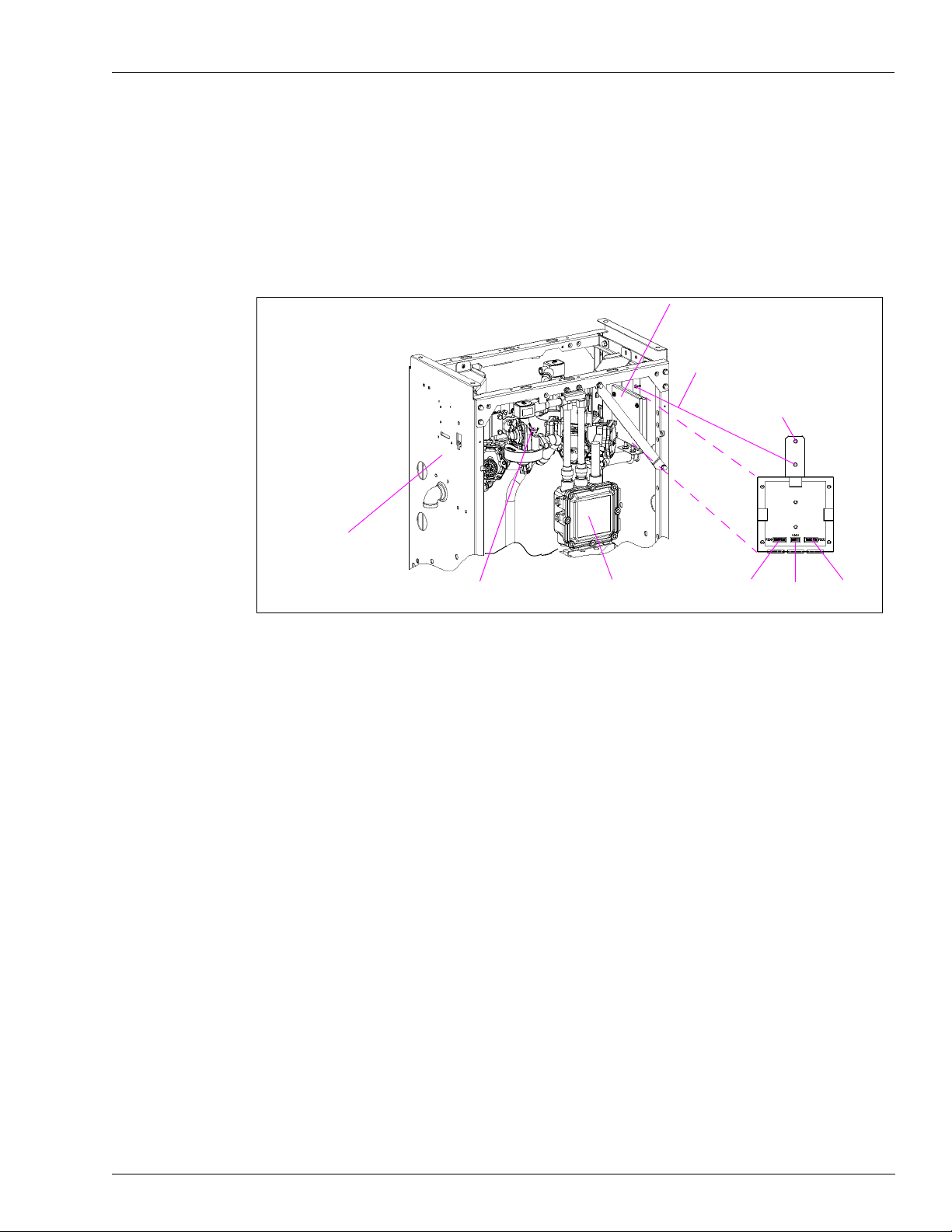
1 Install the T-Meter module onto two clinch studs located on the inside of the side column
(Figure 2, install on either side).
Note: Locate T-Meter module so cables can reach appropriate probe connectors.
Figure 2: Example of Installed T-Meter Module
Installation
T19405-G4 T-Meter Module
lower clinch stud location
upper clinch stud
mounting hole
side column
probe location
(another on other side)
2
Connect the T-Meter module cables as follows (Figure 3):
junction box
P200 P201 P202
• J200 connector on first R20148-G3 cable to P200 connector on T19405-G4 module
• PTP1 connector on first R20148-G3 cable to RTD Probe A1 connector
• J202 connector on second R20148-G3 cable to P202 connector on T19405-G4 module
• PTP5 connector on second R20148-G3 cable to RTD Probe B1 connector
• J201 connector on R20147-G1 cable to P201 connector on T19405-G4 module
Note: The P1S connector on the R20147-G1 cable is not connected at this time; it will be
connected in the Installing I.S. Barrier Assembly section which follows.
MDE-4556 Gasboy ATC Kits M06875K00X Installation Manual • July 2006 Page 9
Page 10

Installation
R20148-G3
R20147-G1
R20148-G3
Figure 3: Cable Block Diagram for T-Meter Module
Route the T-Meter module cables using the following considerations:
3
• Place cables along bottom of hydraulic support rail to prevent damage from screws.
• Be careful to not damage cables when routing over brackets.
• Foam blocks will help to keep cables from falling during routing.
• Use Sealant, TPS or equivalent, to seal ends of any unused connectors to prevent damage
by moisture.
• Use up to four Q10178-03 cable ties to secure cables so connectors are located inside rail
away from moisture and cables do not have excessive slack.
• Adjust foam blocks into final position after cables and connectors are in place.
• All cables should be clear of moving components.
Page 10 MDE-4556 Gasboy ATC Kits M06875K00X Installation Manual • July 2006
Page 11

Installing I.S. Barrier Assembly
The kit parts used in this section are:
• K81105-20 Wire Nut Connector
• Two Q10178-03 Cable Ties
• T19428-G1 115 VAC ISB Assembly
1 Remove 3/4-inch plug from far right-hand opening on top of junction box.
2 Install ISB directly into junction box as shown in Figure 4.
Figure 4: ISB Installation
Junction Box
Installation
T19428-G1
I.S. Barrier
3
Route ISB wires (with connector P1S) back onto ISB and secure with a Q10178-03 cable tie.
4 Run these wires up the junction box conduit and secure to conduit with Q10178-03 cable tie.
5 Connect P1S of the R20147-G1 cable (Figure 3) to J1S of the ISB cable (Figure 7 on page 15).
Locate connector in rail away from moisture.
The green, orange, and grey wires from the ISB are not connected at this time; they will be
connected later in “Connecting ISB Wires and Cable” on page 15.
MDE-4556 Gasboy ATC Kits M06875K00X Installation Manual • July 2006 Page 11
Page 12

Installation
Installing ATC Controller Board
CAUTION
The printed circuit boards (PCBs) and integrated circuits (ICs) within the dispenser are sensitive to
electrostatic discharge (ESD) caused by static electricity. ESD damages electronic parts.
Use the following guidelines when installing the K94160-01 software or handling sensitive
parts.
• Touch an unpainted metal surface to discharge any static electricity buildup.
• Use a wrist strap connected to a grounded metal frame or chassis. Dispenser must be
connected to an AC source with power OFF.
wrist strap
• Place removed PCBs or ICs, if any, on a grounded antistatic mat or in an antistatic bag.
The kit parts used in this section are:
• K94160-01 ATC Software Kit
• R19527-G1 34-conductor Calibration Switch Cable Assembly
• R19667-G1 34-conductor Ribbon Cable Assembly
• R20146-G2 10-conductor Keypad Interface Cable Assembly
• T20569-G1 ATC Controller Board
1 Insert K94160-01 software from kit into position U5 on the T20569-G1 ATC Controller board
(Figure 5).
Figure 5: T20569-G1 ATC Controller Board
P307
Install K94160-01
software in position U5.
JP1
used in “Completing
Installation” on page 16
programming switch
· left = OFF (normal use)
· right = ON (program use only) – used in “Programming the ATC Option” on page 18
Page 12 MDE-4556 Gasboy ATC Kits M06875K00X Installation Manual • July 2006
Page 13

Installation
2 Insert ATC Controller board into top slot of card cage.
If necessary, rearrange boards in the following order, top to bottom:
• T20569-G1 ATC Controller
• M05200A001 Retail Pulse Out
• T20011-G1 Pump Controller
3 Connect existing R17995-G7 cable to the following connectors (Figure 6 on page 14):
• P301 on T20569-G1 ATC Controller board
• P101 on M05200A001 Retail Pulse Out board
• P201 on T20011-G1 Pump Controller board
4 Unplug existing R19667-G1 cable from connector P205 of T20011-G1 Pump Controller board
(leaving other end connected to connector P105 of M05200A001 Retail Pulse Out board) and
connect loose end to connector P305 on T20569-G1 ATC Controller board (Figure 6).
5 Connect new R19667-G1 cable from kit to the following connectors (Figure 6):
• P405 on T20569-G1 ATC Controller board
• P205 on T20011-G1 Pump Controller board
6 Unplug existing R19951-G1 keypad cable from connector P203 of T20011-G1 Pump
Controller board and connect it to connector P303A on T20569-G1 ATC Controller board
(Figure 6).
7 Connect new R20146-G2 cable from kit to the following connectors (Figure 6):
• P303 on T20569-G1 ATC Controller board
• P203 on T20011-G1 Pump Controller board
8 Unplug existing T17768-G1 display cable from connector P204 on T20011-G1 Pump
Controller board and connect it to new R19527-G1 calibration switch cable from the kit
(Figure 6); connect the other end of the new R19527-G1 calibration switch cable to the P204A
connector on T20569-G1 ATC Controller board (Figure 6).
9 Connect other new R19667-G1 cable from kit to the following connectors (Figure 6):
• P304 on T20569-G1 ATC Controller board
• P204 on T20011-G1 Pump Controller board
10 Connect the existing R20128-G1 cable from the conduit to connector P307 on T20569-G1
ATC Controller board (Figure 6).
MDE-4556 Gasboy ATC Kits M06875K00X Installation Manual • July 2006 Page 13
Page 14

Installation
Figure 6: Cable Connections Between Boards for ATC
To conduit
existing R20128-G1
To d i s p l a y
existing T17768-G1
new R19527-G1
To k e y pad
existing R19951-G1
Page 14 MDE-4556 Gasboy ATC Kits M06875K00X Installation Manual • July 2006
Page 15

Connecting ISB Wires and Cable
1 Remove junction box cover using 1/2-inch socket wrench. Save all bolts.
2 Run grey and orange wires of R20128-G1 cable down conduit into junction box (Figure 7).
3 Connect wires using K81105-20 wire nut connectors as shown below and in Figure 7.
ISB Wires Junction Box R20128-G1 Wires Function
Orange – Orange Power
Grey – Grey
Green Ground stud –
Figure 7: Wiring Diagram for ISB and R20128-G1 Cable in Junction Box
Installation
Ground
ground
orange wire
R20128-G1
green wire
J1S
T19428-G1
ISB Assembly
junction box
grey wire
Connect J307 on R20128-G1 cable (Figure 7) to connector P307 on T20569-G1 ATC
4
Controller board (Figure 8).
J307
conduit
K81105-20
wire nut
connector
(1 of 2)
MDE-4556 Gasboy ATC Kits M06875K00X Installation Manual • July 2006 Page 15
Page 16

Installation
Figure 8: ISB to ATC Controller and T-Module Assembly Connections
Note: For simplification, the J1S-to-P1S and junction box connections are not shown.
R20128-G1
(existing)
T19428-G1 ISB
Assembly
R20147-G1
R20148-G3
side A probe
Notes:
1. Installed in “Installing I.S. Barrier Assembly” on page 11.
2. Installed in “Installing ATC Controller Board” on page 12.
3. Installed in “Installing the T-Meter Module and Cables” on page 9.
4. Installed in “Installing Filter Manifold and Probe” on page 7.
1
3
J201 to P201
3
4
3
J307 to P307
T20569-G1 ATC
Controller
T19405-G4 T-Meter
Module Assembly
R20148-G3
side B probe
2
3
4
3
Completing Installation
!
WARNING
!
Spilled or leaking fuels in the vicinity of electrical junction boxes can be hazardous if
boxes are not properly closed.
Serious fire/explosion and injury/death could result.
Replace all bolts and tighten junction box cover before turning on unit AC power. Do not
use gaskets on junction box covers.
1 Place conversion labels, nameplates, any extra cable ties, and additional hardware on upper
shelf.
2 Securely attach junction box cover with all bolts using the 1/2-inch socket wrench.
3 Turn power ON (including lights) as follows:
• Reconnect multiple disconnects.
• Turn system circuit breakers on.
• Turn on associated STP power.
• Turn on power to all pumps/dispensers on same isolation relay, if used.
• Turn on system battery.
• Remove OSHA lock-outs and tag-outs.
• Turn on shear valve.
Page 16 MDE-4556 Gasboy ATC Kits M06875K00X Installation Manual • July 2006
Page 17

Installation
4 Do an ATC master reset on T20569-G1 ATC Controller board by installing a jump jack on JP1
(Figure 5 on page 12) and powering the unit up. Wait for the ATC to completely come up and
display error code 110; then remove the jump jack from JP1.
5 Do a pump master reset on the appropriate display board.
6 Reprogram the unit.
7 Test unit for correct operation.
8 Check for leaks around M04607B003 Filter Manifold and probe/thermowell.
9 Close hydraulics area door.
10 Close electronics area door.
MDE-4556 Gasboy ATC Kits M06875K00X Installation Manual • July 2006 Page 17
Page 18

Programming the ATC Option
Programming the ATC Option
Switch ON the programming switch located on ATC Controller board (Figure 5 on page 12).
At power up:
• Programmed units will flash “104” and then, normal information.
• Non-programmed units will flash “100” which indicates the units must be programmed
per How To Program Each Fueling Position below.
How To Program Each Fueling Position
Note: If programming switch is set to OFF, this procedure will not work.
1 Press 1 0 0.
2 Press ENTER.
Money Position will display “1”.
Money Position shows which meter is selected.
(Meter: 1 through 8)
Volume Position will display “1”.
Volume Position shows which fuel type has been selected.
(Fuel Type: 1-gasoline, 2-diesel)
PPU Position will display “730”.
PPU Position shows which fuel density has been selected for the corresponding meter.
[Fuel Density (kg/m
Note: The Fuel Density default is 730.
Main Display
Information
The software will sequence through each meter position for you to assign the fuel type desired.
3 Select fuel type and press ENTER.
4 Sequence through each meter position and verify desired fuel type by pressing ENTER.
3
): gasoline-730, diesel-840]
1
1
730
Money Position:
Current Meter
Volume Position:
Fuel Type
PPU Position:
Fuel Density
5 Switch OFF the programming switch on ATC controller board (Figure 5 on page 12).
6 Press F2 to exit ATC programming mode.
7 Weights and Measures auditor will put a seal on the programming switch (Figure 5).
8 Close electronics door.
Page 18 MDE-4556 Gasboy ATC Kits M06875K00X Installation Manual • July 2006
Page 19

How To Access ATC Mode Information
Example of How To View Last Transaction
1 Enter 3-digit keypad code for information type desired
(see Definition/Function of ATC Codes below).
2 Press ENTER.
3 Press 1 for Meter Position One information.
4 Press ENTER.
5 Record the information.
6 Continue to press each position number for corresponding position information.
7 Press ENTER.
Programming the ATC Option
8 Press F2 to exit ATC Mode.
(Wait for 1-minute timeout if F2 is nonfunctional.)
Definition/Function of ATC Codes
100 Programming Code
Instructions for programming ATC option are given in “How To Program Each Fueling
Position” on page 18.
200 Inspection Mode
Access this mode to obtain a precise reading of ATC system operation during an actual
transaction. This is the most accurate means of checking ATC system accuracy because
temperature readings are displayed during transaction.
Pure product only: Program a blender for 100%, otherwise the PPU display shows error code
105-product error.
• Money display-shows uncompensated volume
• Volume display-shows compensated volume
• PPU display-shows real-time temperature (in degrees Celsius).
300 View Last Transaction
Access this mode after a transaction. This mode can be used as a basic check to make sure
ATC system is operating properly. Temperature displayed in this mode is an average during
the last transaction. Do not use this mode to verify the accuracy of ATC system.
There are no blender restrictions.
• Money display-shows uncompensated volume.
• Volume display-shows compensated volume.
• PPU display-shows average temperature (in degrees Celsius).
MDE-4556 Gasboy ATC Kits M06875K00X Installation Manual • July 2006 Page 19
Page 20

Programming the ATC Option
301 Display Volume Correction Factor (VCF)
• Money display-shows product number.
• PPU display- shows volume correction factor.
302 Display Density
PPU display-shows programmed density information for selected meter.
303 Display Temperature
PPU display-shows current product temperature for selected meter.
304 Display Gross Volume Totals
Volume and PPU displays-shows a 10-digit number representing the cumulative
uncompensated volume total of the selected meter for a pure product.
500 Software Version
Main display-shows software version number.
600 Troubleshoot Probe
Access this mode to troubleshoot probes. There should be a small change in readings every
second if T-Meter and controller board are working properly. Each probe can be checked by
entering meter number.
• Money display-pulse width in terms of counts
• Volume display-probe resistance in ohms
• PPU display-shows the temperature of probe (in degrees Celsius)
601 Probe History
Use this mode to display probe history since ATC was installed. This is useful for
troubleshooting intermittent probes or probe connections. Access each probe by entering
meter number.
• Money display-shows probe number entered
• Volume display-shows total number of probe range errors logged
• PPU display-shows total number of missing probe pulse errors
Page 20 MDE-4556 Gasboy ATC Kits M06875K00X Installation Manual • July 2006
Page 21

ATC Error Codes
The following list describes ATC error codes that you may observe. These codes are useful
when troubleshooting a problem.
Error Code Error Displayed Description
Programming the ATC Option
00 NO ERROR No errors - no code displayed
100 PROGRAMMING ERROR All fuel types not programmed
101 ROM CHECKSUM Controller ROM checksum error
102 RAM ERROR Controller RAM write/read error
103 T-METER DEAD Not receiving any T-meter pulses
104 T-METER SYNC Receiving T-meter pulses, but with errors
105 PRODUCT ERROR Multiple product selected
106 RAMP RANGE ERROR Gasboy use only
107 RANGE ERROR FOR PROBE Probe out of range
108 MISSING ERROR Probe information missing
109 PULSER ERROR Pulser fail
110 RESET JJ ERROR Reset jump jack is installed
111 RAM CORRUPTED RAM data corrupted
112 NO INPUT TIMER No timer A interrupts occurring
113 NO OUTPUT TIMER No timer B interrupts occuring
114 POWER FAIL ERROR Power fail signal stuck
115 RECURSION ERROR Read T-meter interrupt recursion
MDE-4556 Gasboy ATC Kits M06875K00X Installation Manual • July 2006 Page 21
Page 22

Programming the ATC Option
Pump Error Codes
The following list describes pump error codes that you may observe. These codes are useful
when troubleshooting a problem.
Error Code Description
22 Not Used
23 Grade Assignment Changed
24 Conversion Factor Changed/ Not Programmed
25 Two-Wire/Stand- Mode Changed
26 No Conversion Factor Table
27 Side A* Two-Wire ID Changed
28 Side B* Two-Wire ID Changed
29 Pump Timeout Error
30 Not Used
31 Totals Data Error
32 Pulser Count Error
34 Not Used
35 Configuration Data Error
36 Unit Type Configuration Code Changed
37 PIN Code 1 Changed
38 PIN Code 2 Changed
39 Cast/Credit Option Changed
41 Side Exists Option Changed
42 PPU Options Changed
43 Not Used
44 Pump Handle Up at Power Up
* Side A is the Junction box opening side; side B is the opposite side.
Atlas™ is a trademark of Gasboy Inc.
®
Allen
is a registered trademark of Industrial Fasteners, Inc.
Phillips® is a registered trademark of Phillips Screw Company.
®
SAF-T-LOK
Teflon
is a registered trademark of SAF-T-LOK Chemical Corporation.
®
is a registered trademark of E.I. Du Pont de Memours and Company.
© 2006 GASBOY
7300 West Friendly Avenue • Post Office Box 22087
Greensboro, North Carolina 27420
Phone (800) 444-5529 • http://www.gasboy.com • Printed in the U.S.A.
MDE-4556 Gasboy ATC Kits M06875K00X Installation Manual • July 2006
 Loading...