

Page 1

Introduction
This document provides information on installing replacement motors in Atlas™ units, along
with the requisite belts and pulleys. While installing the new motor, pumping unit pressures
will also need to be set to ensure problem-free operation.
Atlas Motor Kits
Kit No. Description
M06699K001 Atlas Motor Kit, 1 HP, 60HZ, 1PH
M06699K002 Atlas Motor Kit, 1 HP, 50HZ, 1PH
MDE-4541
Atlas™ Motor Kit M06699KXXX Installation
February 2006
Required Reading
Before installing a kit, the installer must read, understand, and follow:
• This manual
• NFPA 30A, The Automotive and Marine Service Station Code
• NFPA 70, The National Electric Code
• Applicable federal, state and local codes and regulations
Failure to do so may adversely affect the safe use and operation of the equipment.
Note: This kit must be installed by a Gasboy Authorized Service Contractor (ASC) to ensure
warranty.
Required Equipment
• Voltmeter with clamp on amp probe
• General mechanics tools
MDE-4541 Atlas™ Motor Kit M06699KXXX Installation • February 2006 Page 1
Page 2

Parts List
Atlas Motor Parts List for M06699K001
Part Number Description
R14213-32 Motor 1 HP, 60 Hz, 1 PH 1
R06711-52 V Belt 4L290 1
R18900-27 Pulley A Belt, 2.50 PD 1
Atlas Motor Parts List for M06699K002
Part Number Description
R14213-33 Motor 1 HP, 50 Hz, 1 PH 1
R06711-52 V Belt 4L290 1
R18900-32 Pulley A Belt, 3.00 PD 1
Quantity
per Kit
Quantity
per Kit
Page 2 MDE-4541 Atlas™ Motor Kit M06699KXXX Installation • February 2006
Page 3
Important Safety Information
Important Safety Information
This section introduces the hazards and safety precautions
associated with installing, inspecting, maintaining or servicing
this product. Before performing any task on this product, read
this safety information and the applicable sections in this
manual, where additional hazards and safety precautions for
your task will be found. Fire, explosion, electrical shock or
pressure release could occur and cause death or serious
injury if these safe service procedures are not followed.
Preliminary Precautions
You are working in a potentially dangerous environment of
flammable fuels, vapors, and high voltage or pressures. Only
trained or authorized individuals knowledgeable in the related
procedures should install, inspect, maintain or service this
equipment.
Emergency Total Electrical Shut-Off
The first and most important information you must know is
how to stop all fuel flow to the pump and island. Locate the
switch or circuit breakers that shut-off all power to all fueling
equipment, dispensing devices, and submerged turbine
pumps (STPs).
!
WARNING
!
The EMERGENCY STOP, ALL STOP, and
PUMP STOP buttons at the cashier’s station
WILL NOT shut off electrical power to the
pump/dispenser.
Read the Manual
Read, understand and follow this manual and any other
labels or related materials supplied with this equipment. If
you do not understand a procedure, call a Gasboy Authorized
Service Contractor or call the Gasboy Service Center at
1-800-444-5529. It is imperative to your safety and the safety
of others to understand the procedures before beginning
work.
Follow the Regulations
There is applicable information in NFPA 30A; Automotive and
Marine Service Code, NFPA 70; National Electrical Code (NEC),
OSHA regulations and federal, state, and local codes which
must be followed. Failure to install, inspect, maintain or
service this equipment in accordance with these codes,
regulations and standards may lead to legal citations with
penalties or affect the safe use and operation of the
equipment.
Replacement Parts
Use only genuine Gasboy replacement parts and retrofit kits
on your pump/dispenser. Using parts other than genuine
Gasboy replacement parts could create a safety hazard and
violate local regulations.
Safety Symbols and Warning Words
This section provides important information about warning
symbols and boxes.
Alert Symbol
Total Electrical Shut-Off Before Access
Any procedure requiring access to electrical components or
the electronics of the dispenser requires total electrical shutoff of that unit. Know the function and location of this switch
or circuit breaker before inspecting, installing, maintaining, or
servicing Gasboy equipment.
Evacuation, Barricading and Shut-Off
Any procedures requiring accessing the pump/dispenser or
STPs requires the following three actions:
- An evacuation of all unauthorized persons and vehicles
using safety tape, cones or barricades to the effected units
- A total electrical shut-off of that unit
This means that even if you activate these
stops, fuel may continue to flow uncontrolled.
You must use the TOTAL ELECTRICAL SHUTOFF in the case of an emergency and not only
these cashier station “stops.”
This safety alert symbol is used in this manual and
on warning labels to alert you to a precaution which must be
followed to prevent potential personal safety hazards. Obey
safety directives that follow this symbol to avoid possible
injury or death.
Signal Words
These signal words used in this manual and on warning
labels tell you the seriousness of particular safety hazards.
The precautions that follow must be followed to prevent
death, injury or damage to the equipment.
DANGER: Alerts you to a hazard or unsafe practice
!
which will result in death or serious injury.
WARNING: Alerts you to a hazard or unsafe
!
practice that could result in death or serious injury.
CAUTION with Alert symbol: Designates a hazard
!
or unsafe practice which may result in minor injury.
CAUTION without Alert symbol: Designates a
hazard or unsafe practice which may result in
property or equipment damage
Working With Fuels and Electrical Energy
Prevent Explosions and Fires
Fuels and their vapors will become explosive if ignited.
Spilled or leaking fuels cause vapors. Even filling customer
tanks will cause explosive vapors in the vicinity of dispenser
or island.
MDE-4541 Atlas™ Motor Kit M06699KXXX Installation • February 2006 Page 3
Page 4

Important Safety Information
No Open Flames
Open flames from matches, lighters, welding torches
or other sources can ignite fuels and their vapors.
No Sparks - No Smoking
Sparks from starting vehicles, starting or using power tools,
burning cigarettes, cigars or pipes can also ignite fuels and
their vapors. Static electricity, including an electrostatic
charge on your body, can cause a spark sufficient to ignite
fuels and their vapors. After getting out of a vehicle, touch the
metal of your vehicle to discharge any electrostatic charge
before you approach the dispenser island.
Working Alone
It is highly recommended that someone who is capable of
rendering first aid be present during servicing. Be familiar
with Cardiopulmonary Resuscitation (CPR) methods if you
are working with or around high voltages. This information is
available from the American Red Cross. Always advise the
station personnel about where you will be working, and
caution them not to activate power while you are working on
the equipment. Use the OSHA Lockout/Tagout procedures. If
you are not familiar with this requirement, refer to information
in the service manual and OSHA documentation.
Working With Electricity Safely
Be sure to use safe and established practices in working with
electrical devices. Poorly wired devices may cause a fire,
explosion or electrical shock. Be sure grounding connections
are properly made. Make sure that sealing devices and
compounds are in place. Be sure not to pinch wires when
replacing covers. Follow OSHA Lockout/Tagout
requirements. Station employees and service contractors
need to understand and comply with this program completely
to ensure safety while the equipment is down.
Hazardous Materials
Some materials present inside electronic enclosures may
present a health hazard if not handled correctly. Be sure to
clean hands after handling equipment. Do not place any
equipment in mouth.
!
WARNING
This area contains a chemical known to the State of
California to cause cancer.
Emergency First Aid
Informing Emergency Personnel
Compile the following information and inform emergency
personnel:
• Location of accident (for example, address, front/back of
building, and so on)
• Nature of accident (for example, possible heart attack,
run over by car, burns, and so on)
• Age of victim (for example, baby, teenager, middle-age,
elderly)
• Whether or not victim has received first aid (for example,
stopped bleeding by pressure, and so on)
• Whether or not a victim has vomited (for example, if
swallowed or inhaled something, and so on)
WARNING
!
Gasoline ingested may cause unconsciousness
and burns to internal organs.
Do not induce vomiting.
Keep airway open.
Oxygen may be needed at scene.
Seek medical advice immediately.
WARNING
!
Gasoline inhaled may cause unconsciousness
and burns to lips, mouth and lungs.
Keep airway open.
Seek medical advice immediately.
WARNING
!
Gasoline spilled in eyes may cause burns to eye
tissue.
Irrigate eyes with water for approximately 15
minutes.
Seek medical advice immediately
WARNING
!
Gasoline spilled on skin may cause burns.
Wash area thoroughly with clear/water.
Seek medical advice immediately.
IMPORTANT: Oxygen may be needed at scene if gasoline
has been ingested or inhaled. Seek medical advice
immediately.
WARNING
!
Lockout/Tagout
Lockout/Tagout covers servicing and maintenance of
This area contains a chemical known to the State of
California to cause birth defects or other reproductive
harm.
machines and equipment in which the unexpected
energization or start up of the machine(s) or equipment or
release of stored energy could cause injury to employees or
personnel. Lockout/Tagout applies to all mechanical,
hydraulic, chemical or other energy, but does not cover
IMPORTANT: Oxygen may be needed at scene if gasoline
has been ingested or inhaled. Seek medical advice
immediately.
electrical hazards. Reference Subpart S of 29 CFR Part 1910
- Electrical Hazards, 29 CFR Part 1910.333 contains specific
Lockout/Tagout provision for electrical hazards.
Page 4 MDE-4541 Atlas™ Motor Kit M06699KXXX Installation • February 2006
Page 5

Installing New Atlas Motor Kits
Preparing for the Installation
1 Request permission from the manager/owner to remove power from the unit and then remove
power using normal procedures. Perform the lockout/tagout safety procedures.
2 Ensure that you have the proper kit for the model unit to be retrofitted.
3 Follow all applicable safety rules and procedures.
Installing the New Atlas Motor
To install the new Atlas motor, remove the old motor and then install the new one, as
explained below:
Removing the Old Motor
1 Disconnect motor wires in the junction box. Mark wires in junction box so that you can be sure
of connecting the new motor correctly.
2 Remove the belt.
Installing New Atlas Motor Kits
Flanged screws
at top of Motor
Deck Plate
Motor Deck
Plate
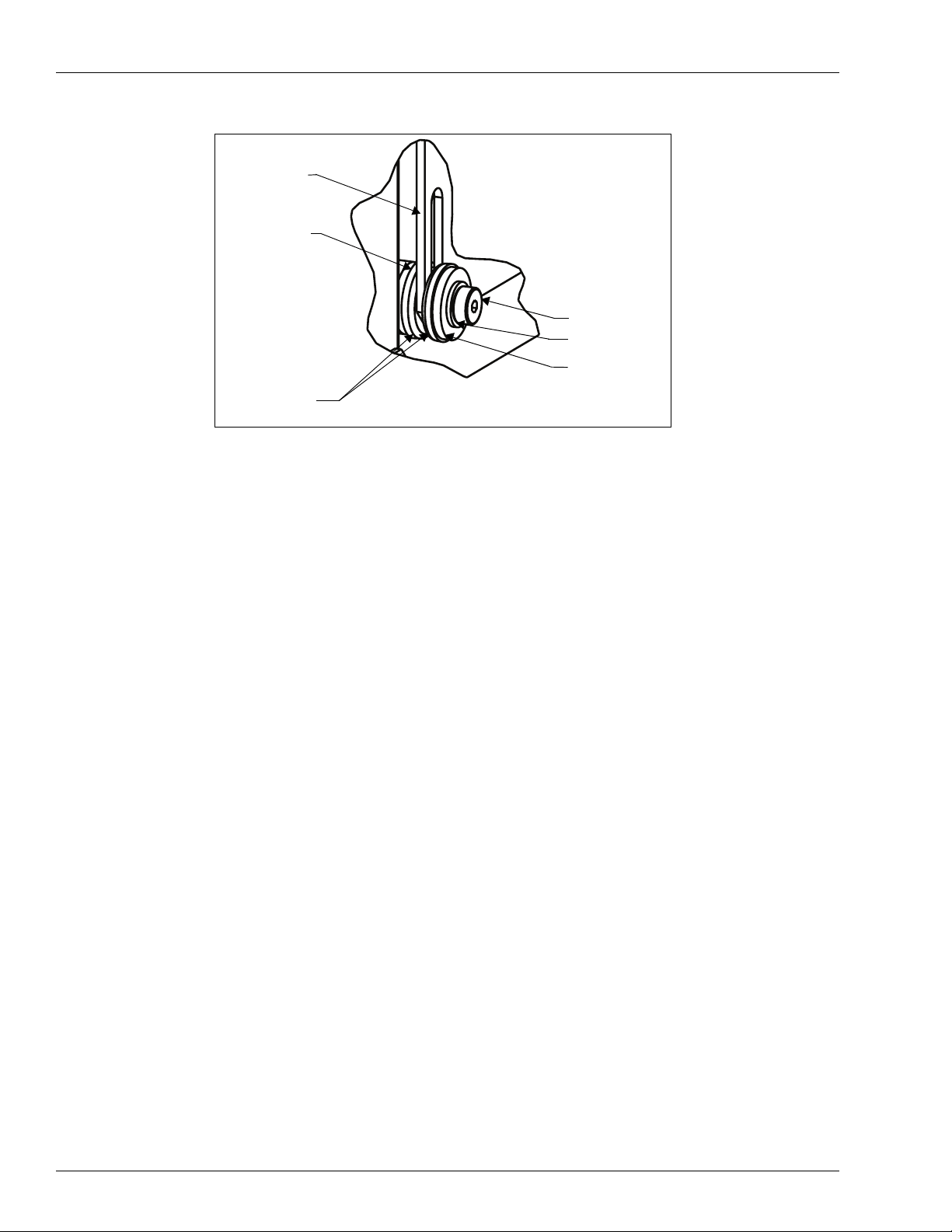
3 Disconnect motor conduit at the expansion union. Refer to Figure 1.
4 Remove the two shoulder bolts on the bottom of the motor deck plate. Remove the washers,
cupped washers and rubber mounts. Refer to
5 While place something underneath the motor to prevent it from dropping suddenly, remove the
two flanged screws from the top of the motor deck plate, and retain the hardware.
6 Remove the motor from the unit.
7 Remove the motor from the motor deck plate and retain the hardware.
Figure 1: Old Atlas Motor
Figure 2. Retain all hardware.
Expansion
Union
Motor Deck
Plate
MDE-4541 Atlas™ Motor Kit M06699KXXX Installation • February 2006 Page 5
Page 6
Installing New Atlas Motor Kits
Figure 2:
Motor Installation Mount
Motor Deck
Plate
Rubber
Mounts (2)
Cupped
Washers
Shoulder
Bolt
Steel
Washer
Rubber
Mount
Installing the New Motor
1 Attach the new motor to the motor deck plate and tighten the four nuts.
2 Transfer the motor conduit from the old motor to the new.
3 Insert the motor and deck plate assembly into the unit.
4 Thread the motor wiring through the conduits into the junction box.
5 Insert the two flanged screws through the slots in the top of the deck plate through the clinch-
nuts on the pump mounting plate flange.
6 Replace the rubber mounts, cupped washers and washers and the shoulder bolts in the slots on
the bottom of the deck plate and thread the shoulder bolts into the clinch-nuts in the bottom
frame plate.
7 Connect the expansion union and tighten the conduit.
8 Attach the new motor pulley to the motor shaft, align it with the pump pulley and tighten.
9 Using the proper tool, such as a crow bar, lift the motor up and place the new belt onto the
pulleys.
10 Using the proper tool, such as a crow bar, push the motor down enough to adjust the tension on
the belt to 45 lbs. If tension gauge is unavailable, adjust the tension until there is about 1/2 inch
of play midway between the pulleys.
Note: Do not increase the tension above 45 lbs. This may result in shorter pump and motor
life.
11 Tighten the two screws on the top of the deck plate.
Page 6 MDE-4541 Atlas™ Motor Kit M06699KXXX Installation • February 2006
Page 7

Installing New Atlas Motor Kits
12 Tighten the two shoulder bolts on the bottom of the deck plate.
13 Check belt alignment and tension. Readjust, if necessary.
14 Connect the motor wires in the junction box.
15 Ensure that the voltage on the motor is set correctly by checking the motor power select switch
in front of the motor. Adjust, if necessary. Refer to
Figure 3: Atlas Pump - Motor Select Switch.
Figure 3.
Motor power select
switch - shown in low
voltage setting (110 volt
nominal)
Verifying Performance
1 Verify completion of the reassembly.
2 Connect the amp probe to a power leg of the motor.
3 Operate the unit and record the initial readings.
Parameter Reading
Full Flow Amperage
Bypass Amperage
Bypass Voltage
Note: To maximize the flowrate, the pumping unit bypass valve spring preload will need to be
adjusted. The maximum allowable load on the new motor is 5.5 amps at 220 volts
(nominal) and 11 amps at 110 volts nominal.
MDE-4541 Atlas™ Motor Kit M06699KXXX Installation • February 2006 Page 7
Page 8

Installing New Atlas Motor Kits
Optimizing the Adjustment on the Bypass Spring Preload
If the amperage from the initial test is low and the flowrate needs increasing, follow this
procedure to adjust the bypass preload. Do not increase the preload if the amperage is at the
maximum.
Note: Before making adjustments, ensure that the motor has been switched off.
To optimize the adjustment on the bypass spring preload, proceed as follows:
1 Remove the adjustment cap on the pumping unit. Refer to Figure 4, which shows adjustment
cap removed.
Figure 4:
2 If the amperage from the initial test is low, turn the adjustment screw clockwise and increase
Atlas Pump - Pressure Pump and Bypass Screw
Pressure Port Ref
Adjustable Bypass
Screw
Vacuum Port Ref
the preload (and thus the flowrate and motor load).
Note: If the initial bypass voltage is below 205 volts for a 220-volt system, or below 100 volts
on a 110-volt system, the wiring is insufficient to handle full motor loads. In this case,
the maximum amperage needs to be set to a maximum of 4.9 amps on a 220-volt system
and 9.5 amps on a 110-volt system. Refer to
3 Check the amperage at full flow and at bypass (both must be checked to verify proper loading
Figure 3.
on the motor).
4 Adjust the screw to obtain just below the maximum amperage setting (4.9 amps on a 220-volt
system and 9.5 amps on a 110-volt system).
5 Replace the adjustment screw cap. Disconnect the amp probe, replace the junction box cover
and button-up the unit.
Completing Installation
Inform the manager/owner that power will be restored to the unit and then restore power using
.
Atlas™ is a trademark of Gasboy.
normal procedures. Remove the lockout/tagout and return to normal operation.
© 2006 GASBOY
7300 West Friendly Avenue • Post Office Box 22087
Greensboro, North Carolina 27420
Phone 1-800-444-5529 • http://www.gasboy.com • Printed in the U.S.A.
MDE-4541 Atlas™ Motor Kit M06699KXXX Installation • February 2006
 Loading...