

Page 1

Introduction
This manual provides installation instructions for Atlas™ Models 8700K, 8800K, 9100K,
9800K balanced system Vapor Recovery (VR) kit M06430K00X.
Self Contained Vapor Recovery Kits
Kit No. Description
M06430K001 VR Kit, 1 Grade 1 Hose Pump, Electronic
M06430K002 VR Kit, 2 Grade 2 Hose Pump, Electronic
M06430K003 VR Kit, 1 Grade 2 Hose Pump, Electronic
M06430K004 VR Kit, 1 Grade 1 Hose Pump, Mechanical
M06430K005 VR Kit, 2 Grade 2 Hose Pump, Mechanical
M06430K006 VR Kit, 1 Grade 2 Hose Pump, Mechanical
MDE-4522A
Atlas™ Self-Contained Pump Vapor
Recovery Kit M06430K00X Installation
November 2006
Required Reading
Before installing a kit, the installer must read, understand, and follow:
• This manual
• NFPA 30A, The Automotive and Marine Service Station Code
• NFPA 70, The National Electric Code
• Applicable federal, state and local codes and regulations
Failure to do so may adversely affect the safe use and operation of the equipment.
Note: This kit must be installed by a Gasboy Authorized Service Contractor (ASC) to ensure
warranty.
Required Tools and Materials
The following tools are needed to install the VR kit:
• Standard wrench set
• Drill (capable of accepting a 5/8-inch masonry drill bit)
• 5/8-inch masonry drill bit
• Flat-tip screwdriver
• Cross-tip screwdriver
• Level (capable of checking vertical plumb)
• Pipe compound (UL
• White lithium-based grease
®
-classified gas- and oil-resistant)
MDE-4522A Atlas™ Self-Contained Pump Vapor Recovery Kit M06430K00X Installation • November 2006 Page 1
Page 2

Introduction
Parts Lists
Note: Parts in these kits include the Vapor Recovery Parts in the appropriate tables below,
plus the parts included in the Hose and Hose Retriever Parts List. The difference
between kits K001/K004, K002/K005, and K003/K006 is in the Nozzle Boot (item 19)
listed in “Hose and Hose Retriever Parts List” on page 3.
V a por Recovery Parts List for 1 Grade 1 Hose M06430K001 and M06430K004
See Figure 2 and Figure 3 for item identification.
Quantity
Item Part Number Description
2 066817 Splitter, Dispenser Mount, Emco A4041-002 (Figure 1)1
4 M00415B011 Screw Metric M8X25 6
5 M00415B003 Nut, Metric, Hex Serrd. Flg. (M8) 8
7 M06495B001 Bracket, Atlas Balanced Support 1
8 R11496-40 Pipe Nipple 3/4” NPT X 2.75” 1
9 K74225 Pipe Union, Female 1
10 M06494A001 Tube Assy., Atlas Balanced Vapor 1
11 M00703B001 U-bolt Metric 1
per Kit
V a por Recovery Parts List for 2 Grade Self-Contained M06430K002 and
M06430K005
See Figure 2 and Figure 4 for item identification.
Item Part Number Description
2 066817 Splitter, Dispenser Mount, Emco A4041-002 (Figure 1)2
4 M00415B011 Screw Metric M8X25 10
5 M00415B003 Nut, Metric, Hex Serrd. Flg. (M8) 14
7 M06495B001 Bracket, Atlas Balanced Support 1
8 R11496-40 Pipe Nipple 3/4” NPT X 2.75” 2
9 K74225 Pipe Union, Female 2
10 M06494A001 Tube Assy., Atlas Balanced Vapor 2
11 M00703B001 U-bolt Metric 2
Quantity
per Kit
V a por Recovery Parts List for 1 Grade 2 Hose M06430K003 and
M06430K006
See Figure 2 and Figure 5 for item identification.
Quantity
Item Part Number Description
2 066817 Splitter, Dispenser Mount, Emco A4041-002 (Figure 1)2
4 M00415B011 Screw Metric M8X25 10
5 M00415B003 Nut, Metric, Hex Serrd. Flg. (M8) 12
7 M06495B001 Bracket, Atlas Balanced Support 1
8 R11496-40 Pipe Nipple 3/4” NPT X 2.75” 2
9 K74225 Pipe Union, Female 2
10 M06496A001 Tube Assy., Atlas Balanced Vapor 1
11 M00703B004 U-bolt Metric 1
per Kit
Page 2 MDE-4522A Atlas™ Self-Contained Pump Vapor Recovery Kit M06430K00X Installation • November 2006
Page 3

Figure 1: Emco Splitter A4041-002 (Gasboy Part Numb er 066817)
Hose and Hose Retriever Parts List
See Figure 6 for item identification.
Quantity
Item Part Number Description
1 032671 Clamp and Reel Assembly 1
2 063838 Support Post 1
3 017930 Cap plug 1-1/2" 1
4 051956 Screw 5/16”-18 x 2”, SS 3
5 068079 Washer 5/16”, SS 4
6 068874 Washer, Lock 5/16”, SS 4
7 063200 Spacer, 3-1/4” 1
8 013250 Bolt 5/16” (Anchor) 1
9 Q10554-12 Plug, Button 1
10 Q10624-23 Screw 5/16”-18 x 4-1/4” 1
11 064560 3/4" Swivel 1
12 038502 Nozzle-Emco VR 1
13 030301 Hose GY 7.5' 1
15 HHS5X009BKX1 Hose 5/8" HW 9” LG 1
16 K02297 ¾" to 1" Bushing 1
17 044007 Breakaway 1
18 030303 Hose GY 4.5' 1
19 003336 Boot-Nozzle, Electronic
M05632B001 Boot-Nozzle, Mechanical
20 033719 Hook-Nozzle Kit 1
21 026850 Gasket, Nozzle Boot 1
per Hose
Introduction
1
MDE-4522A Atlas™ Self-Contained Pump Vapor Recovery Kit M06430K00X Installation • November 2006 Page 3
Page 4

Important Safety Information
Important Safety Information
This section introduces the hazards and safety precautions
associated with installing, inspecting, maintaining or servicing
this product. Before performing any task on this product, read
this safety information and the applicable sections in this
manual, where additional hazards and safety precautions for
your task will be found. Fire, explosion, electrical shock or
pressure release could occur and cause death or serious
injury if these safe service procedures are not followed.
Preliminary Precautions
You are working in a potentially dangerous environment of
flammable fuels, vapors, and high voltage or pressures. Only
trained or authorized individuals knowledgeable in the related
procedures should install, inspect, maintain or service this
equipment.
Emergency Total Electrical Shut-Off
The first and most important information you must know is
how to stop all fuel flow to the pump and island. Locate the
switch or circuit breakers that shut-off all power to all fueling
equipment, dispensing devices, and submerged turbine
pumps (STPs).
!
WARNING
!
The EMERGENCY STOP, ALL STOP , and PUMP
STOP buttons at the cashier’s station WILL NOT
shut off electrical power to the pump/dispenser.
Read the Manual
Read, understand and follow this manual and any other
labels or related materials supplied with this equipment. If you
do not understand a procedure, call a Gasboy Authorized
Service Contractor or call the Gasboy Service Center at 1800-444-5529. It is imperative to your safety and the safety of
others to understand the procedures before beginning work.
Follow the Regulations
There is applicable information in NFPA 30A; Automotive and
Marine Service Code, NFPA 70; National Electrical Code (NEC),
OSHA regulations and federal, state, and local codes which
must be followed. Failure to install, inspect, maintain or
service this equipment in accordance with these codes,
regulations and standards may lead to legal citations with
penalties or affect the safe use and operation of the
equipment.
Replacement Parts
Use only genuine Gasboy replacement parts and retrofit kits
on your pump/dispenser. Using parts other than genuine
Gasboy replacement parts could create a safety hazard and
violate local regulations.
Safety Symbols and Warning Words
This section provides important information about warning
symbols and boxes.
Alert Symbol
This means that even if you activate these stops, fuel
may continue to flow uncontrolled.
You must use the TOTAL ELECTRICAL SHUTOFF in the case of an emergency and not only these
cashier station “stops.”
Total Electrical Shut-Off Before Access
Any procedure requiring access to electrical components or
the electronics of the dispenser requires total electrical shutoff of that unit. Know the function and location of this switch
or circuit breaker before inspecting, installing, maintaining, or
servicing Gasboy equipment.
Evacuation, Barricading and Shut-Off
Any procedures requiring accessing the pump/dispenser or
STPs requires the following three action s:
- An evacuation of all unauthorized persons and vehicles
using safety tape, cones or barricades to the effected units
- A total electrical shut-off of that unit
This safety alert symbol is used in this manual and on
warning labels to alert you to a precaution which must be
followed to prevent potential personal safety hazards. Obey
safety directives that follow this symbol to avoid possible
injury or death.
Signal Words
These signal words used in this manual and on warning labels
tell you the seriousness of particular safety hazards. The
precautions that follow must be followed to prevent death,
injury or damage to the equipment
DANGER - This signal word is used to alert you to a
hazard to unsafe practice which will result in death or
serious injury
WARNING - This alerts you to a hazard or unsafe
practice that could result in death or serious injury.
CAUTION with Alert symbol - This signal word
designates a hazard or unsafe practice which may
result in minor injury.
CAUTION without Alert symbol - When used by itself,
CAUTION designates a hazard or unsafe practice
which may result in property or equipment damage.
Working With Fuels and Electrical Energy
Prevent Explosions and Fires
Fuels and their vapors will become explosive if ignited. Spilled
or leaking fuels cause vapors. Even filling customer tanks will
cause explosive vapors in the vicinity of dispenser or island.
Page 4 MDE-4522A Atlas™ Self-Contained Pump Vapor Recovery Kit M06430K00X Installation • November 2006
Page 5
Important Safety Information
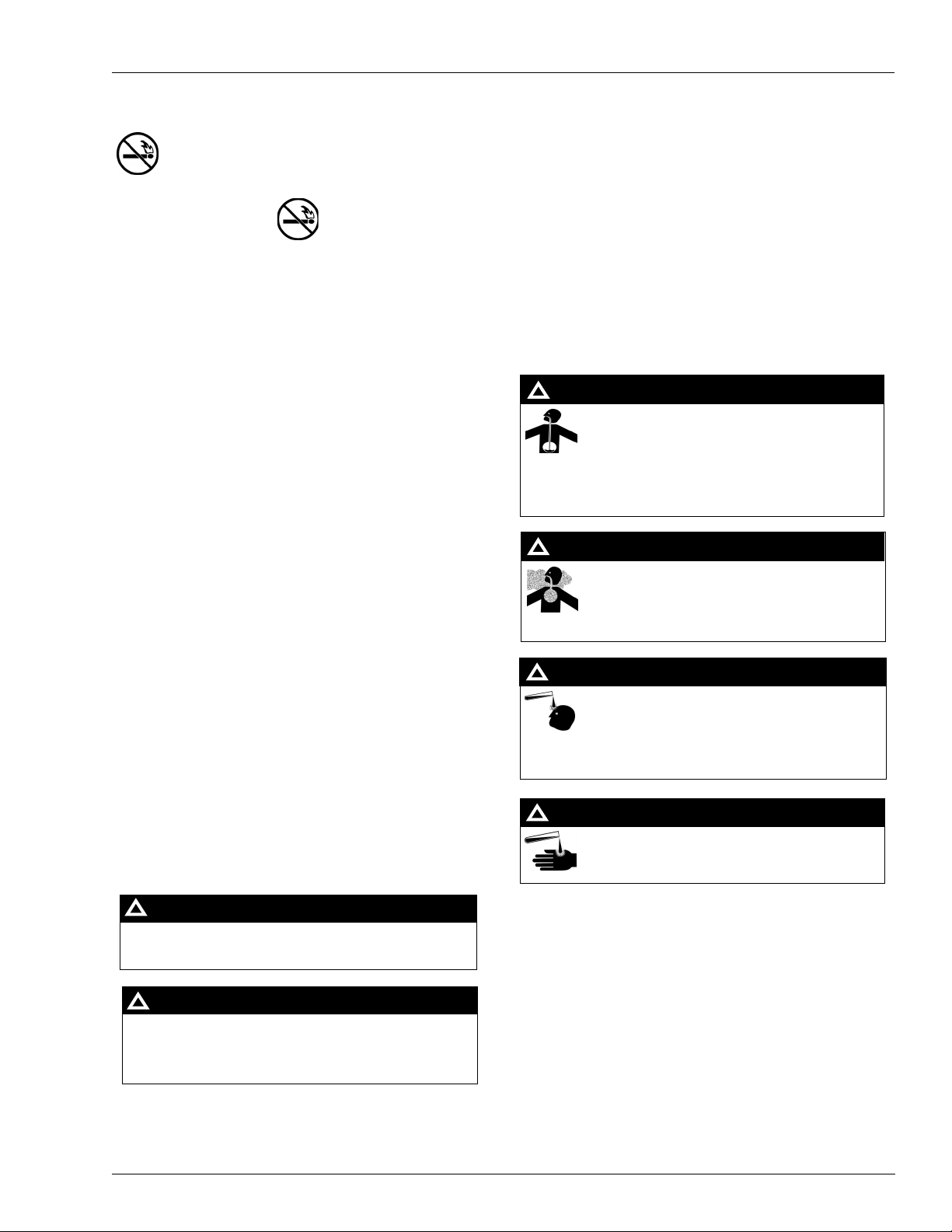
No Open Flames
Open flames from matches, lighters, welding t orches
or other sources can ignite fuels and their vapors.
No Sparks - No Smoking
Sparks from starting vehicles, starting or using power tools,
burning cigarettes, cigars or pipes can also ignite fuels and
their vapors. Static electricity, including an electrostatic
charge on your body, can cause a spark sufficient to ignite
fuels and their vapors. After getting out of a vehicle, touch the
metal of your vehicle to discharge any electrostatic charge
before you approach the dispenser island.
Working Alone
It is highly recommended that someone who is capable of
rendering first aid be present during servicing. Be familiar
with Cardiopulmonary Resuscitation (CPR) methods if you
are working with or around high voltages. This information is
available from the American Red Cross. Always advise the
station personnel about where you will be working, and
caution them not to activate power while you are working on
the equipment. Use the OSHA tag out and lock out
procedures. If you are not familiar with this requirement, refer
to information in the service manual and OSHA
documentation.
Working With Electricity Safely
Be sure to use safe and established practices in working with
electrical devices. Poorly wired devices may cause a fire,
explosion or electrical shock. Be sure grounding connections
are properly made. Make sure that sealing devices and
compounds are in place. Be sure not to pinch wires when
replacing covers. Follow OSHA Lock-Out and Tag-Out
requirements. Station employees and service contractors
need to understand and comply with this program completely
to ensure safety while the equipment is down.
Emergency First Aid
Informing Emergency Personnel
Compile the following information for emergency personnel:
Location of accident (for example, address, front/back of
building, and so on.)
Nature of accident (for example, possible heart attack, run
over by car, burns, and so on.)
Age of victim (for example, baby, teenager, middle-age,
elderly.)
Whether or not victim has received first aid (for example,
stopped bleeding by pressure, and so on.)
Whether or not a victim has vomited (for example, if
swallowed or inhaled something, and so on.)
WARNING
!
Gasoline ingested may cause unconsciousness and
burns to internal organs.
Do not induce vomiting.
Keep airway open.
Oxygen may be needed at scene.
Seek medical advice immediately.
WARNING
!
Gasoline inhaled may cause unconsciousness and
burns to lips, mouth and lungs.
Keep airway open.
Seek medical advice immediately.
WARNING
!
Gasoline spilled in eyes may cause burns to eye
tissue.
Irrigate eyes with water for approximately 15
minutes.
Seek medical advice immediately
Hazardous Materials
Some materials present inside electronic enclosures may
present a health hazard if not handled correctly. Be sure to
clean hands after handling equipment. Do not place any
equipment in mouth.
!
WARNING
This area contains a chemical known to the State of
California to cause cancer.
WARNING
!
Gasoline spilled on skin may cause burns.
Wash area thoroughly with clear/water.
Seek medical advice immediately.
IMPORTANT: Oxygen may be needed at scene if gasoline
has been ingested or inhaled. Seek medical advice
immediately.
Lockout/Tagout
WARNING
!
This area contains a chemical known to the State of
California to cause birth defects or other reproductive harm.
Lockout/Tagout covers servicing and maintenance of
machines and equipment in which the unexpected
energization or start up of the machine(s) or equipment or
release of stored energy could cause injury to employees or
personnel. Lockout/Ta gout applies to all mechanical,
hydraulic, chemical or other energy, but does not cover
electrical hazards. Reference Subpart S of 29 CFR Part 1910
IMPORTANT: Oxygen may be needed at scene if gasoline
has been ingested or inhaled. Seek medical advice
- Electrical Hazards, 29 CFR Part 1910.333 contains specific
Lockout/Tagout provision for electrical hazards.
immediately.
MDE-4522A Atlas™ Self-Contained Pump Vapor Recovery Kit M06430K00X Installation • November 2006 Page 5
Page 6

Installing the Vapor Recovery Kit
Installing the Vapor Recovery Kit
Preparation
1 Request permission from the manager/owner to remove power from the unit; then remove
power using normal procedures. Perform the lockout/tagout safety procedures.
2 Ensure you have the proper kit for the dispenser model to be retrofitted.
3 Be prepared to follow all applicable safety rules and procedures.
Mounting the Vapor Recovery Piping
CAUTION
Use a UL-approved joint compound on all pipe threads. DO NOT use Teflon® tape.
1 See “Parts Lists” on page 2 for the appropriate kit and refer to Figure 2 through Figure 5.
2 Screw the 3/4-inch x 2-1/2 inch pipe nipple into the splitter on the flange side and tighten.
Figure 2: Pump Mounting
Atlas balanced support bracket
Insert the nipple through the splitter hole in the frame, place four M8x25 screws and M8 nuts,
3
Screw, metric M8x25
U-bolt
and tighten them.
4 Place the 3/4-inch pipe union onto the nipple.
5 Place the other half of the 3/4-inch pipe union to the adapter end of the copper tube assembly.
6 Attach the support bracket to the bottom of the pump mounting plate as shown in Figure 2 and
insert two M8x25 screws and M8 nuts, and tighten them.
7 Install the copper tube assembly to the unit by coupling the union.
8 Install and tighten the U-bolt(s) and nuts, and tighten the union.
9 Install the connection to the underground tank using an appropriately-sized union.
Page 6 MDE-4522A Atlas™ Self-Contained Pump Vapor Recovery Kit M06430K00X Installation • November 2006
Page 7

Installing the Vapor Recovery Kit
Figure 3: Vapor Recovery Kit M06430K001 and M06430K004
VAPOR PIPING PARTS LIST
K
MDE-4522A Atlas™ Self-Contained Pump Vapor Recovery Kit M06430K00X Installation • November 2006 Page 7
Page 8

Installing the Vapor Recovery Kit
Figure 4: Vapor Recovery Kit M06430K002 and M06430K005
VAPOR PIPING PARTS LIST
K
Page 8 MDE-4522A Atlas™ Self-Contained Pump Vapor Recovery Kit M06430K00X Installation • November 2006
Page 9

Figure 5: Vaopr Recover Kit M06430K003 and M06430K006
Installing the Vapor Recovery Kit
VAPOR PIPING PARTS LIST
K
MDE-4522A Atlas™ Self-Contained Pump Vapor Recovery Kit M06430K00X Installation • November 2006 Page 9
Page 10

Hose and Retriever Installation
Hose and Retriever Installation
Note: See “Hose and Hose Retriever Parts List” on page 3.
Assembling and Installing Product Jumper Hose
Items needed for this procedure are the following:
• Item 11 – 064560 3/4-inch Swivel
• Item 15 – HHS5X009BKX1 3/4-inch HW Hose, 1-foot 4-inches
• Item 16 – K02297 3/4-inch–to–1-inch Bushing
IMPORTANT INFORMATION
Use pipe compound (UL-approved gas- and oil-resistant) on all pipe threads.
1 Mount the 3/4-inch–to–1-inch bushing (item 16) in the dispenser outlet (see Figure 6).
2 Mount the 3/4-inch swivel (item 11) on the 5/8-inch HW hose (item 15).
3 Connect the fixed end of the 3/4-inch HW hose to the bushing in the dispenser outlet and the
other end (with swivel mounted) to the splitter inlet port labeled FUEL.
Figure 6: Hose and Retriever Assembly with Parts Identification
Page 10 MDE-4522A Atlas™ Self-Contained Pump Vapor Recovery Kit M06430K00X Installation • November 2006
Page 11

Mounting the Hose Retriever
Items needed for this procedure are the following:
• Item 1 - 032671 Clamp and Reel Assembly
• Item 2 - 063838 Support Post
• Item 3 - 017930 1-1/2-inch Cap Plug
• Item 4 - 051956 5/16-18 x 2 SS Screw
• Item 5 - 068079 5/16-inch SS Washer
• Item 6 - 068874 5/16-inch SS Lock Washer
• Item 7 - 063200 Spacer, 3-1/4-inch
• Item 8 - 013250 5/16-inch Bolt Anchor
• Item 9 - Q10554-12 Bottom Plug
• Item 10 Q10624-23 5/16-18 x 4-1/4-inch Screw
1 Assemble Clamp and Reel Assembly (item 1) to support post (item 2) with hardware (items 4,
5, and 6) (Figure 6)
2 Install Cap Plug (item 3) in the top of the support post (Figure 6).
3 Install Reel and Support Post Assembly to the side of the dispensing unit and loosely secure
with hardware (items 5, 6, 7, 9, and 10) (Figure 6).
Note: The spacer (item 7) mounts between the post and side panel.
On electronic models, the spacer mounts to the side panel through a pre-existing
plugged hole to the right of the off-side lever stop.
On mechanical models, the spacer mounts to the side panel replacing the off-side lever
stop.
Hose and Retriever Installation
4 Making sure that the support post is plumb, mark and drill a 5/8-inch diameter x 1-3/4-inch
deep hole in the island (Figure 6).
5 Install Bolt Anchor (item 8) in hole. Secure bottom of support post with hardware (items 4, 5,
and 6) (Figure 6).
6 Tighten all hardware installed in step 3.
7 Plug hole in bottom of support post by installing bottom plug (item 9) (Figure 6).
Modifying Nozzle Boot
Items needed for this procedure are the following:
• Item 19 - 003336 Boot, Nozzle (electronic model)
~ OR ~
Item 19 - M05632B001 Boot, Nozzle (mechanical model)
• Item 20 - 033719 Hook, Nozzle Kit
• Item 21 - 026850 Boot Gasket
1 Remove the four screws securing the existing nozzle boot and remove the nozzle boot and
existing gasket. Save screws for reassembly.
2 Mount new Nozzle Boot Gasket (item 21) and Nozzle Boot (item 19) and secure with the
screws saved in step 1 (Figure 6).
MDE-4522A Atlas™ Self-Contained Pump Vapor Recovery Kit M06430K00X Installation • November 2006 Page 11
Page 12

Hose and Retriever Installation
3 Remove the hardware from the existing nozzle hook. Save all mounting hardware for
reassembly.
4 Remove the two plugs from the lower mounting holes of side panel place them in the two
upper holes.
5 Install the new Nozzle Hook Kit (item 20) in the two lower holes in the side panel and secure
using mounting hardware saved in step 3 (Figure 6).
Mounting Hose to Retriever
Items needed for this procedure are the following:
• Item 12 – 038502 Emco VR Nozzle
• Item 13 – 030301 GY Hose, 7.5 feet
• Item 17 – 044007 Breakaway
• Item 18 – 030303 GY Hose, 4.5 feet
1 Using white lithium-based grease, lubricate both ends of the 7.5-foot GY hose threads (item
13) and O-rings.
2 Thread one end of the hose into the Emco splitter (item 14, Figure 6) on the dispenser unit.
3 Thread the breakaway (item 17) onto the other end of the hose.
4 Using white lithium-based grease, lubricate both ends of the 4.5-foot GY hose threads (item
18) and O-rings.
5 Thread one end of the hose into the breakaway. Thread the Emco nozzle (item 12) onto the
other end of the hose.
6 Tighten all connections securely (four connections).
7 Install the clamp on the clamp and reel assembly (item 1) to the hose. Position the clamp on
the hose such that the hose does not touch the ground when the nozzle is positioned in the
boot.
8 Pull out the hose and check the operation of the clamp and reel assembly retriever and also
check the lay of the hose.
Completing Installation
1 Inform the manager/owner that power will be restored to the unit; then restore power using
normal procedures. Remove the lockout/tagout and return to normal operation.
2 Release the emergency shutoff valve.
3 Test the system for leaks.
Page 12 MDE-4522A Atlas™ Self-Contained Pump Vapor Recovery Kit M06430K00X Installation • November 2006
Page 13

Hose and Retriever Installation
MDE-4522A Atlas™ Self-Contained Pump Vapor Recovery Kit M06430K00X Installation • November 2006 Page 13
Page 14

Hose and Retriever Installation
GASBOY® is a registered trademark of Gilbarco Inc. Atlas™ is a trademark of Gilbarco Inc.
Teflon® is a registered trademark of E. I. DuPont de Nemours and Company.
®
UL
is a registered trademark of Underwriters’ Laboratories, Inc.
© 2006 GASBOY.
7300 West Friendly Avenue • Post Office Box 22087
Greensboro, North Carolina 27420
Phone 1-800-444-5529 • http://ww w.gasboy.com • Printed in the U.S.A.
MDE-4522A Atlas™ Self-Contained Pump Vapor Recovery Kit M06430K00X Installation • November 2006
 Loading...