

Page 1

Introduction
This manual provides installation instructions for Atlas™ Pulser Kits M06245K001 through
M06245K011. The kits and associated models covered in this manual are listed and described
in the
Required Reading
Before installing a kit, the installer must read, understand, and follow:
• This manual
• NFPA 30A, The Automotive and Marine Service Station Code
• NFPA 70, The National Electric Code
• Applicable federal, state and local codes and regulations
MDE-4506A
Atlas™ Pulser Kits M06245K0XX Installation
May 2006
Kit Identification section.
Failure to do so may adversely affect the safe use and operation of the equipment.
Note: This kit must be installed by a Gasboy Authorized Service Contractor (ASC) to ensure
Required Tools
The following tools are required to install the Pulser Kits:
warranty.
• Wrench Set
• Flat tip screwdriver
• Cross tip screwdriver
• Punches (to remove and install pins)
MDE-4506A Atlas™ Pulser Kits M06245K0XX Installation · May 2006 Page 1
Page 2

Introduction
Kit Identification
Kit Number Description
M06245K001 - KIT PLSR 10:1 TWIN Pulser and Coupling Assembly; 10:1 Volume, 91 & 87
M06245K002 - KIT PLSR 100:1 TWIN Pulser and Coupling Assembly; 100:1 Volume, 91 &
M06245K003 - KIT PLSR 1:1 TWIN Pulser Assembly; 1:1 Volume, 91 TWIN EXCEPT
M06245K004 - KIT PLSR 10:1 SINGLE Pulser and Coupler Assembly; 10:1 Volume, 91 & 87
M06245K005 - KIT PLSR 100:1 SINGLE Pulser and Coupler Assembly; 100:1 Volume, 91 & 87
M06245K006 - KIT PLSR 1:1 SINGLE Pulser Assembly; 1:1 Volume, 91 SINGLE EXCEPT
M06245K007 - KIT PLSR CM SINGLE Pulser Assembly; 100:1 MONEY, 87 SINGLE
M06245K008 - KIT PLSR CM TWIN Pulser Assembly; 100:1 MONEY, 87 TWIN
M06245K009 - KIT PLSR 10:1 9140 Pulser Assembly; 10:1 Volume, 9140
M06245K010 - KIT PLSR 1:1 9140 Pulser Assembly; 1:1 Volume, 9140
M06245K011 - KIT PLSR 100:1 9140 Pulser Assembly; 100:1 Volume, 9140
TWIN EXCEPT 9140
87 TWIN EXCEPT 9140
9140
SINGLE EXCEPT 9140
SINGLE EXCEPT 9140
9140
Warranty
For information on warranty, refer to MDE-4255 Gasboy’s Warranty Policy Statement. If you
have any warranty-related questions, contact Gasboy’s Warranty Department at its Greensboro
location.
Page 2 MDE-4506A Atlas™ Pulser Kits M06245K0XX Installation · May 2006
Page 3

K011-
M06245
K010-
M06245
K009-
M06245
KIT
K008-
M06245
KIT
K007-
M06245
K006-
M06245
K005-
M06245
KIT
PLSR
KIT
PLSR
KIT
PLSR
CM
PLSR
CM
PLSR
KIT
PLSR
KIT
PLSR
100:1
1:1
10:1
TWIN
100:1
100:1
SINGLE
1:1
100:1
9140
(QTY)
9140
(QTY)
9140
(QTY)
(QTY)
MONEY
(QTY)
MONEY
(QTY)
SINGLE
(QTY)
SINGLE
KIT
K004-
M06245
KIT
K003-
M06245
KIT
K002-
M06245
KIT
K001-
M06245
10:1
PLSR
1:1
PLSR
100:1
PLSR
10:1
PLSR
(QTY)
SINGLE
TWIN
(QTY)
TWIN
(QTY)
TWIN
(QTY)
027041 2 2 2 1 1 1 - - 1 1 1
056877 4 4 2 2 1 1 2 4 2 1 2
C08682 2 2 2 1 1 1 1 2 1 1 1
Introduction
Description Part Number
CRTN 14.312 X 11.375 X 15 018656 1 1 1 1 1 1 1 1 1 1 1
DECAL, 10:1 PULSER 023596 1 1 - 1 - - - - 1 - 1
ELBOW-CONDUIT 1/2 X 45 M/ 025015 2 2 2 1 1 1 - - 1 1 1
ELBOW-CONDUIT 1/2 X 90 M/ 025045 2 2 2 1 1 1 1 2 - - -
GEAR,
QUANTITY
PLATE AND IDLER GEAR ASSY 027044 2 2 2 1 1 1 - - 1 1 1
HUB-QUAN. SHAFT EXTENSION 031035 2 - 2 1 1 1 - - 1 1 1
KIT-PLSR VR 312020-924 VR 032942 - - - - - - 1 2 - - -
PLSR ASY 1:1;91EK LTR 046969 - - 2 - - 1 - - - 1 -
PLATE-MOUNTNG PULSER 100 046970 2 2 2 1 1 1 - - 1 1 1
PLSR & CPLG ASSY;100:1 046972 - 2 - - 1 - - - - - 1
PULSER & CPLG ASSY; 10:1 046973 2 - - 1 - - - - 1 - -
POLY BAG 5 X 6 047401 1 1 1 1 1 1 1 1 1 1 1
SPACER.94 4 NOM.LENGTH
SPACER TOP.835 NOM.LENGTH 056895 2 2 2 1 2 2 1 2 1 2 1
CONDUIT TEE, MACHINED 064830 1 1 1 1 1 1 1 1 - - -
WASHER, LOCK EXT 1/4 1114 068891 12 12 14 6 7 7 3 6 6 7 6
TIE-WRAP, IDENTIF
(1"X5/16)
SCREW HEX HD CAP FINISHED K14830 6 6 6 3 3 3 3 6 3 3 3
Parts Lists
MDE-4506A Atlas™ Pulser Kits M06245K0XX Installation · May 2006 Page 3
Page 4

K011-
M06245
K010-
M06245
K009-
M06245
KIT
K008-
M06245
KIT
K007-
M06245
K006-
M06245
K005-
M06245
KIT
PLSR
KIT
PLSR
KIT
PLSR
CM
PLSR
CM
PLSR
KIT
PLSR
KIT
PLSR
100:1
1:1
10:1
TWIN
100:1
100:1
SINGLE
1:1
100:1
9140
(QTY)
9140
(QTY)
9140
(QTY)
(QTY)
MONEY
(QTY)
MONEY
(QTY)
SINGLE
(QTY)
SINGLE
K004-
M06245
K003-
M06245
K002-
M06245
K001-
M06245
KIT
KIT
KIT
KIT
10:1
PLSR
1:1
PLSR
100:1
PLSR
10:1
PLSR
(QTY)
SINGLE
TWIN
(QTY)
TWIN
(QTY)
TWIN
(QTY)
Introduction
Description Part Number
ELBOW CNDT 1/2X90 F SPT K42428 1 1 1 1 1 1 1 1 - - -
ELBOW CNDT 1/2X90 M & F K42448 - - - - - - - - 1 1 1
PLUG PIPE 1/2 SQ SOCKET K43850 - - - 1 1 1 1 - - - -
BUSHG FCED RDC 3/4X1/2 K49827 1 1 1 1 1 1 1 1 1 1 1
RING RET 1/4 K76238-41 2 2 2 1 1 1 - - 1 1 1
SCREW TPT HEX WS HD 1/4-2 K85736-39 2 2 2 1 1 1 - - 1 1 1
CONDUIT M05292B001 1 1 1 1 1 - - - - - -
CONDUIT M05293B001 1 1 1 - - - - - - - -
CONDUIT FORMED M05368B001 - - - - - 1 1 1 - - -
CONDUIT FORMED M05369B001 - - - - - - - 1 - - -
CONDUIT 9140 PULSER M06869B001 - - - - - - - - 1 1 1
MOA MECH PULSER CONDUIT M05370 1 1 1 1 1 1 1 1 1 1 1
UNION CNDT M&F 1/2 Q10016-04 3 3 3 2 2 2 2 3 1 1 1
SPIROL PIN.078 X.437 Q10038-35 2 2 2 1 1 1 - - 1 1 1
SCREW HEX HD CAP FINISHED Q10624-37 6 6 6 3 3 3 - - 3 3 3
NIPPLE 3/4 X 3-3/8 R11496-43 1 1 1 - - - - 1 - - -
NIPPLE 3/4 X 3-5/8 R11976-43 - - - 1 1 1 1 - - - -
NIPPLE CNDT 1/2 X 4 R11976-57 1 1 1 1 1 1 1 1 - - -
INSTAL INSTR PULSER KITS MDE-4506 1 1 1 1 1 1 1 1 1 1 1
Page 4 MDE-4506A Atlas™ Pulser Kits M06245K0XX Installation · May 2006
Page 5

Important Safety Information
Important Safety Information
This section introduces the hazards and safety precautions
associated with installing, inspecting, maintaining or servicing
this product. Before performing any task on this product, read
this safety information and the applicable se cti o ns in th is
manual, where additional hazards and safety precautions for
your task will be found. Fire, explosion, electrical shock or
pressure release could occur and cause death or serious
injury if these safe service procedures are not followed.
Preliminary Precautions
You are working in a potentially dangerous environment of
flammable fuels, vapors, and high voltage or pressures. Only
trained or authorized individuals knowledgeable in the related
procedures should install, inspect, maintain or service this
equipment.
Emergency Total Electrical Shut-Off
The first and most important information you must know is
how to stop all fuel flow to the pump and island. Locate the
switch or circuit breakers that shut-off all power to all fueling
equipment, dispensing devices, and submerged turbine
pumps (STPs).
!
WARNING
!
The EMERGENCY STOP, ALL STOP, and
PUMP STOP buttons at the cashier’s station
WILL NOT shut off electrical power to the
pump/dispenser.
Total Electrical Shut-Off Before Access
Any procedure requiring access to electrical components or
the electronics of the dispenser requires total electrical shutoff of that unit. Know the function and location of this switch
or circuit breaker before inspecting, installing, maintaining, or
servicing Gasboy equipment.
Evacuation, Barricading and Shut-Off
Any procedures requiring accessing the pump/dispenser or
STPs requires the following three actions:
This means that even if you activate these
stops, fuel may continue to flow uncontrolled.
You must use the TOTAL ELECTRICAL SHUTOFF in the case of an emergency and not only
these cashier station “stops.”
Read the Manual
Read, understand and follow this manual and any other
labels or related materials supplied with this equipment. If you
do not understand a procedure, call a Gasboy Authorized
Service Contractor or call the Gasboy Service Center at 1800-444-5529. It is imperative to your safety and the safety of
others to understand the procedures before beginning work.
Follow the Regulations
There is applicable information in NFPA 30A; Automotive and
Marine Service Code, NFPA 70; National Electrical Code (NEC),
OSHA regulations and federal, state, and local codes which
must be followed. Failure to install, inspect, maintain or
service this equipment in accordance with these codes,
regulations and standards may lead to legal citations with
penalties or affect the safe use and operation of the
equipment.
Replacement Parts
Use only genuine Gasboy replacement parts and retrofit kits
on your pump/dispenser. Using parts other than genuine
Gasboy replacement parts could create a safety hazard and
violate local regulations.
Safety Symbols and Warning Words
This section provides important information about warning
symbols and boxes.
Alert Symbol
This safety alert symbol is used in this manual and on
warning labels to alert you to a precaution which must be
followed to prevent potential personal safety hazards. Obey
safety directives that follow this symbol to avoid possible
injury or death.
Signal Words
These signal words used in this manual an d on warning labels
tell you the seriousness of particular safety hazards. The
precautions that follow must be followed to prevent death,
injury or damage to the equipment
DANGER - This signal word is used to alert you to a
!
hazard to unsafe practice which will result in death or
serious injury
WARNING - This alerts you to a hazard or unsafe
!
practice that could result in death or serious injury.
CAUTION with Alert symbol - This signal word
!
designates a hazard or unsafe practice which may
result in minor injury.
CAUTION without Alert symbol - When used by itself,
CAUTION designates a hazard or unsafe practice
which may result in property or equipment damage.
- An evacuation of all unauthorized persons and vehicles
using safety tape, cones or barricades to the effected units
- A total electrical shut-off of that unit
MDE-4506A Atlas™ Pulser Kits M06245K0XX Installation · May 2006 Page 5
Working With Fuels and Electrical Energy
Prevent Explosions and Fires
Fuels and their vapors will become explosive if ignited. Spilled
or leaking fuels cause vapors. Even filling customer tanks will
cause explosive vapors in the vicinity of dispenser or island.
Page 6

Important Safety Information
No Open Flames
Open flames from matches, lighters, welding torches
or other sources can ignite fuels and their vapors.
No Sparks - No Smoking
Sparks from starting vehicles, starting or using power tools,
burning cigarettes, cigars or pipes can also ignite fuels and
their vapors. Static electricity, including an electrostatic
charge on your body, can cause a spark sufficient to ignite
fuels and their vapors. After getting out of a vehicle, touch the
metal of your vehicle to discharge any electrostatic charge
before you approach the dispenser island.
Working Alone
It is highly recommended that someone who is capable of
rendering first aid be present during servicing. Be familiar
with Cardiopulmonary Resuscitation (CPR) methods if you
are working with or around high voltages. This information is
available from the American Red Cross. Always advise the
station personnel about where you will be working, and
caution them not to activate power while you are working on
the equipment. Use the OSHA tag out and lock out
procedures. If you are not familiar with this requirement, refer
to information in the service manual and OSH A
documentation.
Working With Electricity Safely
Be sure to use safe and established practices in working with
electrical devices. Poorly wired devices may cause a fire,
explosion or electrical shock. Be sure grounding connections
are properly made. Make sure that sealing devices and
compounds are in place. Be sure not to pinch wires when
replacing covers. Follow OSHA Lock-Out and Tag-Out
requirements. Station employees and service contractors
need to understand and comply with this program completely
to ensure safety while the equipment is down.
Hazardous Materials
Some materials present inside electronic enclosures may
present a health hazard if not handled correctly. Be sure to
clean hands after handling equipment. Do not place any
equipment in mouth.
!
WARNING
This area contains a chemical known to the State of
California to cause cancer.
Emergency First Aid
Informing Emergency Personnel
• Compile the following information for emergency
personnel:
• Location of accident (for example, address, front/back of
building, and so on.)
• Nature of accident (for example, possible heart attack, run
over by car, burns, and so on.)
• Age of victim (for example, baby, teenager, middle-age,
elderly.)
• Whether or not victim has received first aid (for example,
stopped bleeding by pressure, and so on.)
• Whether or not a victim has vomited (for example, if
swallowed or inhaled something, and so on.)
WARNING
!
Gasoline ingested may cause unconsciousness
and burns to internal organs.
Do not induce vomiting.
Keep airway open.
Oxygen may be needed at scene.
Seek medical advice immediately.
WARNING
!
Gasoline inhaled may cause unconsciousness
and burns to lips, mouth and lungs.
Keep airway open.
Seek medical advice immediately.
WARNING
!
Gasoline spilled in eyes may cause burns to eye
tissue.
Irrigate eyes with water for approximately 15
minutes.
Seek medical advice immediately
WARNING
!
Gasoline spilled on skin may cause burns.
Wash area thoroughly with clear/water.
Seek medical advice immediately.
IMPORTANT: Oxygen may be needed at scene if gasoline
has been ingested or inhaled. Seek medical advice
immediately.
WARNING
!
This area contains a chemical known to the State of
California to cause birth defects or other reproductive
harm.
Lockout/Tagout
Lockout/Tagout covers servicing and maintenance of
machines and equipment in which the unexpected
energization or start up of the machine(s) or equipment or
release of stored energy could cause injury to employees or
personnel. Lockout/Tagout applies to all mechanical,
hydraulic, chemical or other energy, but does not cover
IMPORTANT: Oxygen may be needed at scene if gasoline
has been ingested or inhaled. Seek medical advice
immediately.
electrical hazards. Reference Subpart S of 29 CFR Part 1910
- Electrical Hazards, 29 CFR Part 1910.333 contains specific
Lockout/Tagout provision for electrical hazards.
Page 6 MDE-4506A Atlas™ Pulser Kits M06245K0XX Installation · May 2006
Page 7

Installing the Pulser Kit in Twin Units (Kits M06245K001 through M06245K003 and M06245K008)
Installing the Pulser Kit in Twin Units (Kits M06245K001
through M06245K003 and M06245K008)
Preparation
1 Request permission from the manager/owner to remove power from the unit and then remove
power using normal procedures. Observe the lockout/tagout safety procedures.
2 Using the proper key for the unit, unlock and remove the doors from both sides of the unit.
Place the doors in a safe place to prevent damage or scratches.
3 On both sides of the unit, remove the two screws securing the bezel and remove the bezel.
Store the bezels and screws in a safe place for reuse.
4 Remove the screws securing the dial face in place and remove the dial faces from each of the
computers on both sides. Store the dial faces and screws in a safe place to prevent damage or
scratches.
5 Ensure that you have the proper kit for the model dispenser to be retrofitted.
Temporarily Moving the Computers
The computers will have to be temporarily moved to allow space between the units to install
the pulser parts. To move the computers, proceed as follows:
1 Note that there are two drive shafts connected to the computer. Make a note of the exact
position of the shafts. Things to note are:
• Bottom (vertical) shaft is set in a slot on the lower end. The pins on the shaft are in the
shallower slots.
• The side shaft is pinned to the drive shaft in the computer and the mark on the rotating
wheel (on the computer) has a mark on it. The mark must be pointing up when
reassembled to properly align the readout number register.
2 Remove the pin from the side (horizontal) shaft mounted to the computer. Save the pin for
reassembly.
3 Loosen and remove the three mounting bolts securing the computer in place. Save for
remounting.
4 Move the computer to allow adequate space for mounting the pulser parts (out of the dispenser
if necessary). Care must be taken to ensure that the large gear on the side of the computer is
kept in the same "OFF" position.
5 Repeat the procedure for the second computer.
MDE-4506A Atlas™ Pulser Kits M06245K0XX Installation · May 2006 Page 7
Page 8

Installing the Pulser Kit in Twin Units (Kits M06245K001 through M06245K003 and M06245K008)
Installing the Drive Gear on the Meter Computer Shaft
In the kit, locate two 043225 pins, two 031035 hubs, two 027401 gears, and two K76238-41
retaining rings. See
1 On one of the computers, press a pin into the hole in the computer shaft until it is flush on one
side of the shaft. For kits M06245K001 through M06245K003, press the pin into the hole in
the computer quantity shaft. For M06245K008, press the pin into the hole in the computer
money shaft.
Figure 1: Driver Gear on Meter Computer Shaft
Figure 1.
Retaining Ring
Hub
Pin
Computer
Shaft
2 Place a hub on the shaft with the slotted portion of the hub straddling the extending pin and
align the hole in the hub with the pin.
3 Push the pin through the hole in the hub until the pin extends equally on both sides of the hub. 4 Place a gear on the hub and align the pin in the shaft with the bearing slot in the gear. 5 Secure the gear in place by placing a retaining ring in the slot near the end of the shaft. 6 Repeat step 1 through step 5 on the shaft of the other computer.
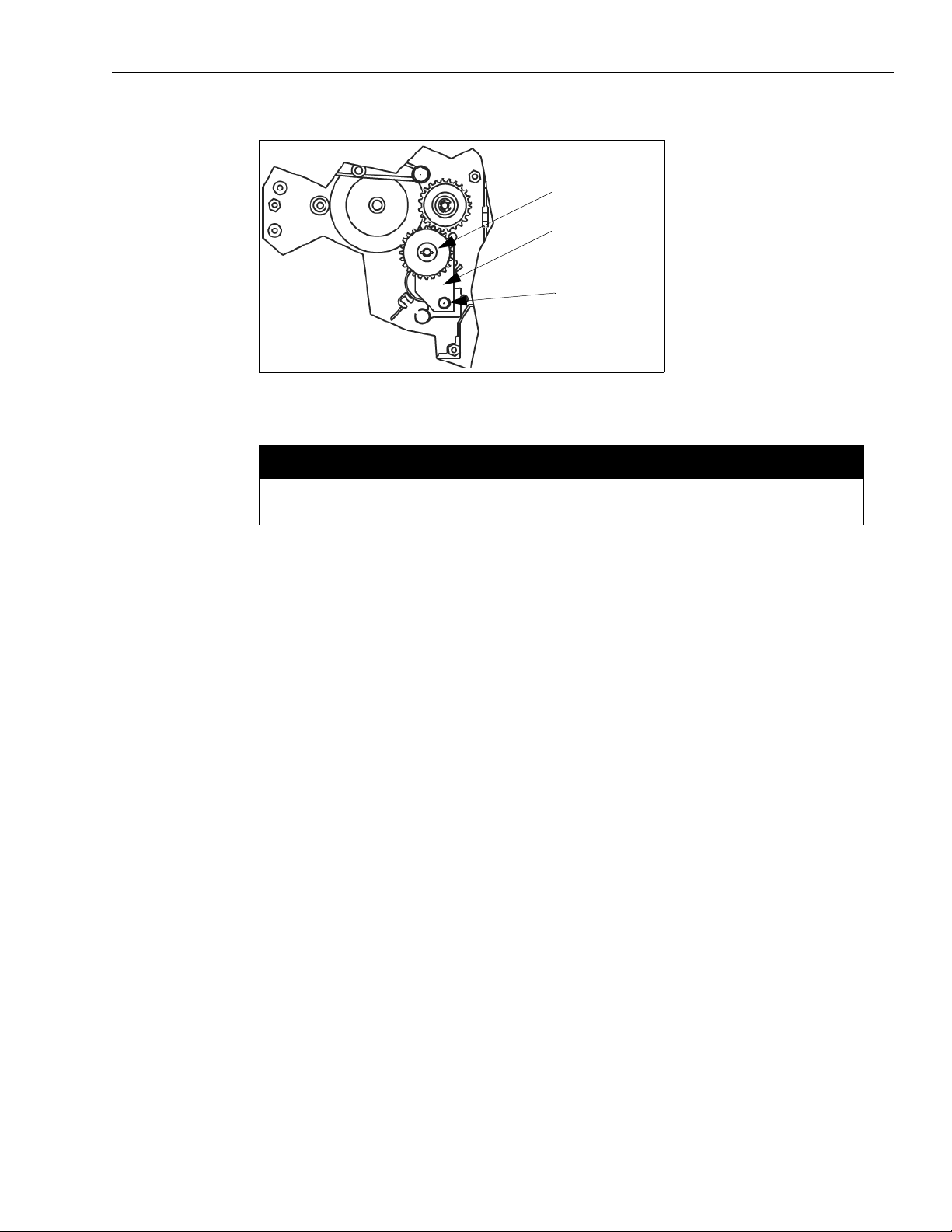
Installing the Plate and Idler Assembly
1 In the kit, locate two K85736-39 screws and two 027044 Plate and Idler Assemblies. See
Figure 2 on page 9.
Note: The 053920 mounting screw for the Plate and Idler Assembly is a self-tapping screw.
Turning the screw into the mounting hole in the computer side frame and then removing
it without the assembly in place will make mounting the assembly easier.
2 At one of the computers, hold the Plate and Idler Gear Assembly in place and loosely secure it
with the mounting screw . The boss and bracket holes in the computer assembly must align for
proper gear meshing with the previously installed gear.
Page 8 MDE-4506A Atlas™ Pulser Kits M06245K0XX Installation · May 2006
Page 9
Installing the Pulser Kit in Twin Units (Kits M06245K001 through M06245K003 and M06245K008)
Figure 2: Plate and Idler Gear Assembly
Idler Gear
Plate and Idler
Gear Assembly
Mounting Screw
(Self tapping)
Note: This illustration is shown rotated 90 degrees from its installed position.
CAUTION
Excessive tightening of the mounting screw will crack the plastic plate.
3 Ensure proper gear position, alignment, and meshing and tighten mounting screw.
4 Repeat step 2 through step 3 to mount the second Plate and Idler Gear Assembly on the other
computer.
Assembling 046970 Pulser Mounting Plate and 0469XX Pulser and
Coupling Assembly
1 In the kit, locate two 046970 mounting plates, two 0469XX* Pulser and Coup ling Assemblies,
six 051805 screws, and six 068891 lock washers.
* The part number depends on which kit is being installed. See “Parts Lists”
on page 3 for the part number.
2 Place the mounting plate on the Pulser and Coupling Assembly, align the three mounting
holes, and loosely secure with three screws and three lock washers.
3 Tighten all screws equally.
4 Repeat step 2 and step 3 for the other mounting plate and pulser and coupling assembly.
MDE-4506A Atlas™ Pulser Kits M06245K0XX Installation · May 2006 Page 9
Page 10

Installing the Pulser Kit in Twin Units (Kits M06245K001 through M06245K003 and M06245K008)
Completing the Assembly and Mounting the Pulser Units
1 In the kit, locate the following parts:
• Two 0469XX* pulser and coupling assemblies
• Two 056895 spacers
• Two 056877 spacers
• Four Q10624-37 screws
• Four 068891 washers
• Two 025015 elbows
• One M05293B001 formed conduit (Kits M06245K001, M 06245K002, and M 06245K003)
• One M05292B001 formed conduit (Kits M06245K001, M 06245K002, and M 06245K003)
• One M05368B001 formed conduit (Kit M06245K008)
• One M05369B001 formed conduit (Kit M06245K008)
* The part number depends on which kit is being installed. See “Parts Lists” on page 3 for
the part number.
2 Feed the pulser and coupling assembly wires through the 025015 elbow and install the elbow
on the pulser and coupling assembly. See
Figure 3.
Figure 3: Pulser and Coupling Assembly
M05293B001 conduit (Kits M06245K001,
M06245K002, and M06245K003)
M05369B001 conduit (Kit M06245K008)
025015 elbows
M05292B001 conduit (Kits M06245K001,
M06245K002, and M06245K003)
Front pulser facing J Box
M05368B001 conduit (Kit M06245K008)
3 Repeat step 2 for the second pulser and coupling assembly.
4 Install the M05292B001 or M05368B001 conduit on the front pu lser and coupling assembly
(the one with the black band near the end of the wires) and the M05293B001 or M05369B001
on the back pulser and coupling assembly.
Note: The front of the dispenser is the side with the junction box. The front pulser (mounts on
the left computer) is the one with the black band near the end of the wires.
Page 10 MDE-4506A Atlas™ Pulser Kits M06245K0XX Installation · May 2006
Page 11

Installing the Pulser Kit in Twin Units (Kits M06245K001 through M06245K003 and M06245K008)
5 On the left computer, remove and discard two assembly screws and replace with the two
spacers in positions shown in
Figure 4. Notice the difference in part numbers and position of
the spacers.
Figure 4: Front Pulser Assembly
056895 Spacers
056877 Spacers
6 Place the front pulser (one with M05292B001 or M05368B001 conduit mounted on it) in
position (installs on the left computer) by positioning the conduit mounted on the pulser
through the slot in the unit between the computers. Ensure that the pinned shaft on the pulser
aligns with the center hole in the idler gear (refer to
Figure 2 on page 9) and the pin seats in the
slot in the gear. The mounting holes in the mounting plate must align with the holes in the
spacers. See
7 Loosely secure in place with two washers and two screws. 8 Ensure that the parts are meshed properly and tighten the screws. 9 Repeat step 2 through step 5 for the second pulser and coupling assembly (installs on the right
Figure 4.
computer).
Remounting the Computers
To remount the computers, proceed as follows:
1 At the side shaft mounting, turn the rotating wheel (on the computer) until the mark on the
wheel is pointing upward.
2 Mount the shaft on the computer and pin it with the pin saved during removal. 3 Mount the vertical shaft in the slot noted during removal (pin in shallow slots). 4 Move the computer in place aligning the mounting holes and ensuring that the two shafts are
properly seated (as noted prior to moving the computers).
CAUTION
Improper alignment can cause meter/computer wear/damage or stalling of the meter/
computer at slow flow rates.
MDE-4506A Atlas™ Pulser Kits M06245K0XX Installation · May 2006 Page 11
Page 12

Installing the Pulser Kit in Twin Units (Kits M06245K001 through M06245K003 and M06245K008)
5 Secure the computer in place with the mounting bolts saved during the initial moving
procedure.
Installing the Remaining Conduit
1 In the kit, locate the parts shown in the appropriate illustration. Refer to Figure 5 on page 12.
Note: Feed wires through conduit and fittings as it is assembled.
2 Install a Q10016-04 conduit union on the formed conduit connected to the pulsers.
For Kits M06245K001, M06245K002, and M06245K003, refer to Figure 5 on page 12.
Figure 5: Dual Volume Mechanical Conduit (M06245K001, K002, and K003)
Elbow, Conduit 1/2x
45 deg (025015)
Formed conduit
Mechanical volume
pulser grade 1
(M05292B001)
Conduit elbow 1/2x
90 deg (K42428)
Conduit Nipple
1/2 Inch (R11976-
43)
Elbow, Conduit 1/2x
90 deg (025045)
Union, conduit 1/2
inch (Q10016-04)
Formed conduit
Mechanical volume
pulser grade 2
(M05293B001)
Union, conduit 1/2
inch (Q10016-04)
Conduit elbow 1/2x
90 deg (K42428)
Conduit Tee 1/2
inch NPT (064830)
Conduit Nipple 1/2x 4
(R11976-57)
Union, conduit 1/2
inch (Q10016-04)
Bushing, Reducing
3/4-1/2 (K49827)
Page 12 MDE-4506A Atlas™ Pulser Kits M06245K0XX Installation · May 2006
Page 13

Installing the Pulser Kit in Twin Units (Kits M06245K001 through M06245K003 and M06245K008)
For Kit M06245K008, refer to Figure 6.
Figure 6: Dual Money Mechanical Pulser Conduit
Formed conduit
Mechanical Money
pulser grade 2
(M05369B001)
Elbow, Conduit 1/2x
90 deg (025045)
Formed conduit
Mechanical Money
pulser grade 1
(M05368B001)
Conduit elbow 1/2
NPT 90 deg (K42428)
Conduit Tee 1/2
inch NPT (064830)
Conduit Nipple 1/2x 4
(R11976-57)
Union, conduit 1/2
inch (Q10016-04)
Conduit Nipple
1/2x 1 5/8 (R11976-43)
Elbow, Conduit 1/2x
90 deg (025045)
Union, conduit 1/2
inch (Q10016-04)
Bushing, Reducing
3/4-1/2 (K49827)
3 Install the K49827 reducer and Q10016-04 union into the junction box as shown in Figure 6. 4 Make the remaining connections as shown in Figure 6.
Connecting the Wires in the Junction Box
1 Remove the screws securing the cover on the junction box. Save screws for remounting. 2 Inside the junction box, connect the two green ground leads from the pulsers to a secure
known ground.
3 Connect the leads for the pulsers, two from the front pulser with black band (mounted to the
left computer) and two from the back pulser (mounted on the right computer) to the leads in
the junction box marked for the pulsers.
4 Remount the junction box cover and secure with the screws removed in step 1.
MDE-4506A Atlas™ Pulser Kits M06245K0XX Installation · May 2006 Page 13
Page 14

Installing the Pulser Kit in Twin Units (Kits M06245K001 through M06245K003 and M06245K008)
Testing/Checking Operation
Only the 10:1 pulser can be tested for operation. Using test equipment, others must be tested
when hooked to the pump/dispenser controller. Test the 10:1 pulser as follows:
1 Inform the manager/owner that power will be restored to the unit and then restore power to the
unit.
2 Connect a mechanical voltmeter on the two orange signal wires.
3 Set the voltmeter to read Ohms.
4 Slowly dispense fuel and observe that the needle deflects upscale for each 1/10 gallon fuel.
Completing the Installation
1 After determining that the pulsers are functioning properly, remount the dial faces on the two
computers and secure with the screws saved during removal.
2 Remount the bezels on both sides of the unit and secure with the screws saved during removal.
3 Remount the doors on both sides of the unit and secure with the keylocks.
4 Inform the manager/owner that the unit can be returned to service.
Page 14 MDE-4506A Atlas™ Pulser Kits M06245K0XX Installation · May 2006
Page 15

Installing the Pulser Kit in Single Unit and 9140 (Kits M06245K004 through M06245K007 and M06245K009 - M06245K011)
Installing the Pulser Kit in Single Unit and 9140
(Kits M06245K004 through M06245K007 and M06245K009 M06245K011)
Preparation
1 Request permission from the manager/owner to remove power from the unit and then remove
power using normal procedures. Observe the lockout/tagout safety procedures.
2 Using the proper key for the unit, unlock and remove the doors from both sides of the unit.
Place the doors in a safe place to prevent damage or scratches.
3 On both sides of the unit, remove the two screws securing the bezel and remove the bezel.
Store bezels and screws in a safe place for reuse.
4 Remove the screws securing the dial face in place and remove the dial faces from both sides of
the computer. Store the dial faces and screws in a safe place to prevent damage or scratches.
5 Ensure that you have the proper kit for the model dispenser to be retrofitted.
Installing the Drive Gear on the Meter Computer Shaft
In the kit, locate a 043225 pin, a 031035 hub, a 027401 gear, and a K76238-41 retaining ring.
Figure 7.
See
1 On the computer, press a pin into the hole in the computer shaft until it is flush on one side of
the shaft. For kits M06245K004 through M06245K006 and M06245K009 - M06245K011,
press the pin into the hole in the computer quantity shaft. For M06245K007, press the pin into
the hole in the computer money sha ft.
Figure 7: Installing Drive Gear on Meter Computer Shaft
Retaining Ring
Hub
Pin
Computer
Shaft
2 Place a hub on the shaft with the slotted portion of the hub straddling the extending pin and
align the hole in the hub with the pin.
3 Push the pin through the hole in the hub until the pin is extending equally on both sides of the
hub.
4 Place a gear on the hub and align the pin in the shaft with the bearing slot in the gear.
5 Secure the gear in place by placing a retaining ring in the slot near the end of the shaft.
MDE-4506A Atlas™ Pulser Kits M06245K0XX Installation · May 2006 Page 15
Page 16

Installing the Pulser Kit in Single Unit and 9140 (Kits M06245K004 through M06245K007 and M06245K009 - M06245K011)
Installing the Plate and Idler Assembly
1 In the kit, locate the K85736-39 screw and the 027044 Plate and Idler Assembly . See Figure 8.
Note: The K85736-39 mounting screw for the Plate and Idler Assembly is a self-tapping
screw. Turning the screw into the mounting hole in the computer side frame and then
removing it without the assembly in place will make mounting the assembly easier.
2 Hold the Plate and Idler Gear Assembly in place and loosely secure with the mounting screw.
The boss and bracket holes in the computer assembly must align for proper gear meshing.
Figure 8: Plate and Idler Gear Assembly
Plate and Idler
Gear Assembly
Mounting
Screw
Note: This illustration is shown rotated 90 degrees from its installed position.
CAUTION
Excessive tightening of the mounting screw will crack the plastic plate.
3 Ensure proper gear position, alignment and meshing and then tighten the mounting screw.
Assembling 046970 Pulser Mounting Plate and 0469XX Pulser and Coupling Assembly
In the kit, locate a 046970 mounting plate, a 0469XX* Pulser and Coupling Assembly, three
K14830 screws, and three 068891 lock washers.
* The part number depends on which kit is being installed. See “Parts Lists” on page 3 for the
part number.
1 Place the mounting plate on the Pulser and Coupling Assembly, align the three mounting
holes, and loosely secure with three screws and three lock washers.
2 Tighten all screws equally.
Page 16 MDE-4506A Atlas™ Pulser Kits M06245K0XX Installation · May 2006
Page 17

Installing the Pulser Kit in Single Unit and 9140 (Kits M06245K004 through M06245K007 and M06245K009 - M06245K011)
Completing the Assembly and Mounting the Pulser Unit on Models 8700 and 9100 except 9140
1 In the kit, locate the parts shown in Figure 9.
2 Feed the pulser and coupling assembly wires through the 025015 elbow and install the elbow
on the pulser and coupling assembly . For Kit M06245K004, M06245K005 and M06245K006,
refer to the illustration below.
Figure 9: Single Volume Mechanical Pulser Conduit
Spacer (056895)
Spacer 0.944
(056877, 056895)
Elbow, Conduit 1/2x
45 (025015)
Conduit elbow 1/2
NPT 90 deg
(K42428)
Conduit Nipple
1/2x 1 5/8 (R11976-43)
Union, conduit 1/2
inch (Q10016-04)
Formed conduit
Mechanical volume
pulser grade1
(M05292B001)
Elbow, Conduit 1/2x
90 deg (025045)
Pipe plug c-sunk 1/2
(K43850
Conduit Tee 1/2
inch NPT (064830)
Conduit Nipple 1/2x 4
(R11976-57)
Union, conduit 1/2
inch (Q10016-04)
Bushing, Reducing
3/4-1/2 (K49827)
MDE-4506A Atlas™ Pulser Kits M06245K0XX Installation · May 2006 Page 17
Page 18

Installing the Pulser Kit in Single Unit and 9140 (Kits M06245K004 through M06245K007 and M06245K009 - M06245K011)
For Kit M06245K007, refer to Figure 10.
Figure 10: Single Money Mechanical Pulser Conduit
Spacer (056895)
Spacer 0.944
(056877, 056895)
Formed conduit
Mechanical Money
pulser grade1
(M05368B001)
Elbow, Conduit 1/2x
90 deg (025045)
Pipe plug c-sunk 1/2
(K43850)
Conduit Tee 1/2 inch
NPT (064830)
Conduit Nipple 1/2x 4
Conduit elbow 1/2
90 deg (K42428)
Conduit Nipple
1/2x 1 5/8
(R11976-43)
Union, conduit 1/2
inch (Q10016-04)
(R11976-57)
Union, conduit 1/2
inch (Q10016-04)
Bushing, Reducing
3/4-1/2 (K49827)
3 Install the M05292B001 or M05368B001 conduit on the pulser and coupling assembly (to t he
elbow installed in
step 2).
4 Remove and discard the two assembly screws and replace them with the two spacers in
positions shown in
Figure 9 on page 17 and Figure 10. Notice the difference in part numbers
and the position of the spacers.
5 Place the pulser in position by positioning the conduit mounted on the pulser through the slot
in the unit. Ensure that the pinned shaft on the pulser aligns with the center hole in the idler
gear and the pin seats in the slot in the gear. The mounting holes in the mounting plate must
align with the holes in the spacers. Refer to
Page 18 MDE-4506A Atlas™ Pulser Kits M06245K0XX Installation · May 2006
Figure 8 on page 16.
Page 19

Installing the Pulser Kit in Single Unit and 9140 (Kits M06245K004 through M06245K007 and M06245K009 - M06245K011)
6 Loosely secure in place with two washers and two screws.
7 Ensure that the parts are meshed properly and tighten the screws.
8 Ensuring that the wires extend through the conduit, make the necessary connections as shown
Figure 9 on page 17 or Figure 10.
in
9 Ensure that the wires extend into the junction box.
Connecting the Wires in the Junction Box
1 Remove the screws securing the cover on the junction box. Save screws for remounting.
2 Inside the junction box, connect the green ground lead from the pulser to a secure known
ground.
3 Refer to your Fuel Management System installation manual for proper wiring of the pulsers.
4 Remount the junction box cover and secure it with the screws removed in step 1.
Testing/Checking Operation
Only the 10:1 pulser can be tested for operation. Using test equipment, others must be tested
when hooked to the pump/dispenser controller. Test the 10:1 pulser as follows:
1 Inform the manager/owner that power will be restored to the unit and then restore power to the
unit.
2 Connect a mechanical voltmeter on the two orange signal wires.
3 Set the voltmeter to read Ohms.
4 Slowly dispense fuel and observe that the needle deflects upscale for each 1/10 gallon fuel.
Completing the Installation
1 After determining that the pulser is functioning properly, remount the dial faces on the
computer and secure them with the screws saved during removal.
2 Remount the bezels on both sides of the unit and secure them with the screws saved during
removal.
3 Remount the doors on both sides of the unit and secure them with the keylocks.
4 Inform the manager/owner that the unit can be returned to service.
MDE-4506A Atlas™ Pulser Kits M06245K0XX Installation · May 2006 Page 19
Page 20

Installing the Pulser Kit in Single Unit and 9140 (Kits M06245K004 through M06245K007 and M06245K009 - M06245K011)
Completing Assembly and Mounting Pulser Unit on Model 9140 (Kits M06245K009, M06245K010 and M06245K011)
1 In the kit, locate the parts shown in Figure 11. 2 Feed the pulser and coupling assembly wires through the 025015 elbow and install the elbow
on the pulser and coupling assembly.
Figure 11: Super-Hi Mechanical Pulser Conduit and Computer Mount
Spacer (056895)
Spacer 0.944
(056877, 056895)
Elbow, Conduit 1/2x
Ref: Differential Assembly
Ref: Plate Assembly ,
Computer Mount
45 deg (025015)
Conduit, Pulser
Mechanical Super-HI
(M06869B001)
Ref: Screw Metric
M6x 16
Ref: Screw self
locking hex head cap
3/8 -24x0.75
grade 5
Elbow, 1/2 x 90MxF
(K42448)
Union, conduit 1/2
inch (Q10016-04)
Bushing, Reducing
3/4-1/2 (K43850)
3 Install the M06869B001 conduit on the pulser and coupling assembly (to the elbow installed
in the previous step).
4 Remove and discard the two assembly screws and replace them with the two spacers in the
position shown in
Figure 11. Notice the difference in part numbers and the position of the
spacers.
Page 20 MDE-4506A Atlas™ Pulser Kits M06245K0XX Installation · May 2006
Page 21

Installing the Pulser Kit in Single Unit and 9140 (Kits M06245K004 through M06245K007 and M06245K009 - M06245K011)
5 Place the pulser in position by positioning the conduit mounted on the pulser through the slot
in the unit. Ensure that the pinned shaft on the pulser aligns with the center hole in the idler
gear and the pin seats in the slot in the gear. The mounting holes in the mounting plate must
align with the holes in the spacers. Refer to
6 Loosely secure in place with two washers and two screws. 7 After careful examination to ensure that the parts are meshed properly, tighten the screws. 8 Ensuring that the wires extend through the conduit, make the necessary connections as shown
Figure 11 on page 20.
in
9 Ensure that the wires extend into the junction box.
Figure 8 on page 16.
Connecting the Wires in the Junction Box
1 Remove the screws securing the cover on the junction box. Save screws for remounting. 2 Inside the junction box, connect the green ground lead from the pulser to a secure known
ground.
3 Refer to your Fuel Management System installation manual for proper wiring of the pulsers. 4 Remount the junction box cover and secure with the screws removed in step 1.
Testing/Checking Operation
Only the 10:1 pulser can be tested for operation. Using test equipment, others must be tested
when hooked to the pump/dispenser controller. Test the 10:1 pulser as follows:
1 Inform the manager/owner that power will be restored to the unit and then restore power to the
unit.
2 Connect a mechanical voltmeter on the two orange signal wires. 3 Set the voltmeter to read Ohms. 4 Slowly dispense fuel and observe that the needle deflects upscale for each 1/10 gallon fuel.
Completing the Installation
1 After determining that the pulser is functioning properly, remount the dial faces on the
computer and secure them with the screws saved during removal.
2 Remount the bezels on both sides of the unit and secure them with the screws saved during
removal.
3 Remount the doors on both sides of the unit and secure them with the keylocks. 4 Inform the manager/owner that the unit can be returned to service.
MDE-4506A Atlas™ Pulser Kits M06245K0XX Installation · May 2006 Page 21
Page 22

Installing the Pulser Kit in Single Unit and 9140 (Kits M06245K004 through M06245K007 and M06245K009 - M06245K011)
.Atlas™ is a trademark of Gasboy.
© 2006 GASBOY
7300 West Friendly Avenue - Post Office Box 22087
Greensboro, North Carolina 27420
Phone 1-800-444-5529 - http://www.gasboy.com -Printed in the U.S.A.
MDE-4506A Atlas™ Pulser Kits M06245K0XX Installation · May 2006
 Loading...