

Page 1

Introduction
Purpose
This manual provides installation instructions for the Commercial Atlas™ (9800K) Automatic
Temperature Compensation (ATC) Kits:
• M05819K001 for 9800K Single Unit
• M05819K002 for 9800K Twin Unit
• M05819K003 for 9850K Single Unit
• M05819K004 for 9850K Twin Unit
Table of Contents
MDE-4431C
Gasboy ATC M05819K00X Kits Installation Manual
February 2013
Topic Page
Introduction 1
Important Safety Information 8
Installing the Commercial Atlas (9800K) ATC Kits 10
Appendix: Totalizer Display Information 28
Required Tools
Following tools are required to install the ATC M05819K00X Kits:
• Open-end Wrench Set
• Flat-blade Screwdriver
®
• Phillips
• Allen
Screwdriver
®
-wrench Set
MDE-4431C Gasboy ATC M05819K00X Kits Installation Manual · February 2013 Page 1
Page 2

Introduction
Parts Lists
ATC M05819K001 Kit for Single Unit (Except 9850K)
Part Number
(see Note) Description Quantity
M06080B001 Kit, ATC Kraus TTC200-1GK 1
Printed Circuit Board (PCB) Assembly in LP-70 Polycase
28017
Sponge 1
SK460A4 460A4 ATC Display Adapter Board (see Figure 1 on page 5) 1
SK461 461A2 Pulser/Handle Adapter Board (see Figure 1 on page 5) 1
27913 Dual Intrinsic Safety Barrier 1
- 5/16-inch Flat Washer (part of 27913) 2
- 5/16-inch Hex Nut (part of 27913) 1
212AY04 Single Probe Connector Assembly 1
W171 Two-wire Harness for Intrinsic Safety Barrier 1
SW199 Probe Assembly 1
20026 Thermowell 1
235-C Thermowell Plug 1
12B02 1/8-inch National Pipe Thread (NPT) Coupling 1
15912 1/8-inch NPT Adapters Drilled to 17/64-inch Inside Diameter (I.D.) 1
103-B02 1/8-inch NPT Couplings 1
W283 Display Adapter Harness 1
W284 Pulser/Handle Ribbon Cable 1
BSN18-C 18-22 American Wire Gauge (AWG) Crimp Splices 10
BC256W White “Volume Corrected to 15° C” Label 2
BC1380 Serialized AV-2322 Nameplate 1
N23760-07 Conduit Seal Washer 2
t-justified part numbers are Kraus part numbers
Note: Left-justified part numbers are Gasboy part numbers; r
contained in the preceding Gasboy part number.
igh
®
Box and BC1379 Mounting
ATC M05819K002 Kit for Twin Unit (Except 9850K)
Part Number
(see Note) Description Quantity
M06080B002 Kit, ATC Kraus TTC200-2GK 1
28017 PCB Assembly in LP-70 Polycase Box and BC1379 Mounting Sponge 1
SK460A4 460A4 ATC Display Adapter Board (see Figure 1 on page 5) 1
SK461 461A2 Pulser/Handle Adapter Board (see Figure 1 on page 5) 1
27913 Dual Intrinsic Safety Barrier 1
- 5/16-inch Flat Washer (part of 27913) 2
- 5/16-inch Hex Nut (part of 27913) 1
212AY05 Dual Probe Connector Assembly 1
W172 Three-wire Harness for Intrinsic Safety Barrier 1
SW199 Probe Assembly 2
20026 Thermowell 2
235-C Thermowell Plug 2
Page 2 MDE-4431C Gasboy ATC M05819K00X Kits Installation Manual · February 2013
Page 3

Part Number
Note
(see
N23760-07 Conduit Seal Washer 2
Note: Left-justified part numbers are Gasboy part numbe
) Description Quantity
122-B02 1/8-inch NPT X 1-inch Coupling 2
15912 1/8-inch NPT Adapters Drilled to 17/64-inch I.D. 2
103-B02 1/8-inch NPT Couplings 2
W283 Display Adapter Harness 1
W284 Pulser/Handle Ribbon Cable 2
BSN18-C 18-22 AWG Crimp Splices 10
BC256W White “Volume Corrected to 15° C” Label 4
BC1380 Serialized AV-2322 Nameplate 1
rs; ri
ght-justified part numbers are Kraus
part numbers contained in the preceding Gasboy part number.
ATC M05819K003 Kit for Single Unit
Part Number
(see Note) Description Quantity
039087 Kit, ATC 9800 Single (TTC200-1G) 1
SK449C PCB Assembly in LP-70 Polycase Box and BC1379 Mounting Sponge
SK460A4 460A4 ATC Display Adapter Board (see Figure 1 on page 5) 1
SK461 461A2 Pulser/Handle Adapter Board (see Figure 1 on page 5) 1
27913 Dual Intrinsic Safety Barrier 1
- 5/16-inch Flat Washer (part of 27913) 2
- 5/16-inch Hex Nut (part of 27913) 1
212AY04 Single Probe Connector Assembly 1
W171 Two-wire Harness for Intrinsic Safety Barrier 1
SW199 Probe Assembly 1
20026 Thermowell 1
235-C Thermowell Plug 1
122-B02 1/8-inch NPT Coupling 1
15912 1/8-inch NPT Adapters Drilled to 17/64-inch I.D. 1
103-B02 1/8-inch NPT Couplings 1
W283 Display Adapter Harness 1
W284 Pulser/Handle Ribbon Cable 1
BSN18-C 18-22 AWG Crimp Splices 10
BC256W White “Volume Corrected to 15° C” Label 2
BC1380 Serialized AV-2322 Nameplate 1
N23760-07 Conduit Seal Washer 2
s; ri
Note: Left-justified part numbers are Gasboy part number
part numbers contained in the preceding Gasboy part number.
ght-justified part numbers are Kraus
1
Introduction
MDE-4431C Gasboy ATC M05819K00X Kits Installation Manual · February 2013 Page 3
Page 4

Introduction
ATC M05819K004 Kit for Twin Unit
Part Number
(see Note) Description Quantity
039086 Kit, ATC 9800TW (TTC200-2G) 1
SK449C PCB Assembly in LP-70 Polycase Box and BC1379 Mounting Sponge 1
SK460A4 460A4 ATC Display Adapter Board (see Figure 1 on page 5) 1
SK461 461A2 Pulser/Handle Adapter Board (see Figure 1 on page 5) 1
27913 Dual Intrinsic Safety Barrier 1
- 5/16-inch Flat Washer (part of 27913) 2
- 5/16-inch Hex Nut (part of 27913) 1
212AY05 Dual Probe Connector Assembly 1
W172 Three-wire Harness for Intrinsic Safety Barrier 1
SW199 Probe Assembly 2
20026 Thermowell 2
235-C Thermowell Plug 2
122-B02 1/8-inch NPT X 1-inch Coupling 2
15912 1/8-inch NPT Adapters Drilled to 17/64-inch I.D. 2
103-B02 1/8-inch NPT Couplings 2
W283 Display Adapter Harness 1
W284 Pulser/Handle Ribbon Cable 2
BSN18-C 18-22 AWG Crimp Splices 10
BC256W White “Volume Corrected to 15° C” Label 4
BC1380 Serialized AV-2322 Nameplate 1
N23760-07 Conduit Seal Washer 2
Note: Left-justified part numbers are Gasboy part
part numbers contained in the preceding Gasboy part number.
numbers; right-
justified part numbers are Kraus
Page 4 MDE-4431C Gasboy ATC M05819K00X Kits Installation Manual · February 2013
Page 5
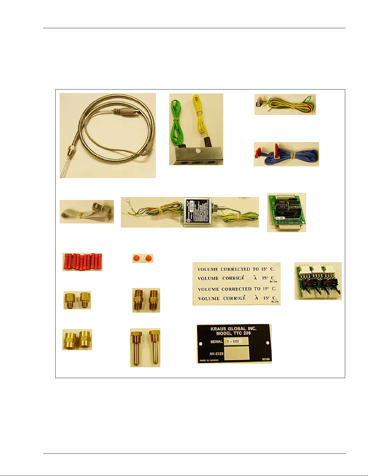
Parts Identification
Probe Assembly (W199)
Display Adapter Harness (W283)
Pulser (W284)/Handle
Ribbon Cable
Single Probe (212AY04)/
Dual Probe Connector
(212AY05) Assembly
Display Adapter
Board (460A4)
Pulser (461A2)/Handle
Adapter Board
Crimp Splices
Thermowell Plugs
(235C)
103-B Couplings
120-B Adapters (BC546)
122-B Nipples
Thermowells (BC407)
Label (BC256W)
Nameplate (BC1380)
Dual Intrinsic Safety Barrier (27913)
Three-wire Harness [W172 (For Twin Unit)]
~OR~
Two-wire Harness [W171 (For Single Unit)]
Figure 1 and Figure 2 on page 6 show the parts in the M05819K00X Kits.
Figure 1: Identification of Parts in Kits
Introduction
MDE-4431C Gasboy ATC M05819K00X Kits Installation Manual · February 2013 Page 5
Note: Kits for single units have only one of these items.
Page 6
Introduction
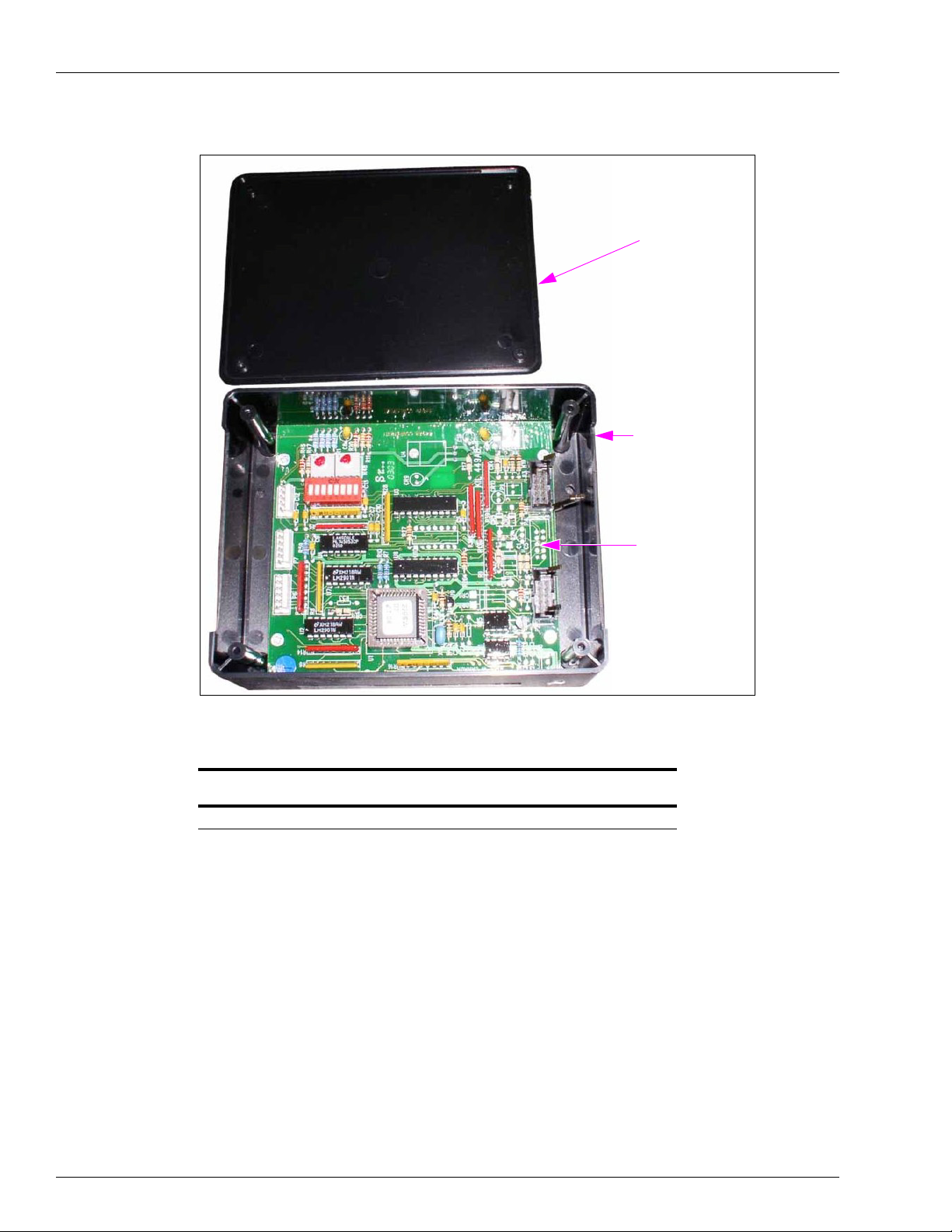
PCB Assembly
(28017 or SK449C)
Polycase Box
(LP-70)
Cover
Figure 2: Polycase Box (LP-70) and Cover with 28017 or SK449C
Related Document
Document
Number Title GOLD Library
MDE-4431 Gasboy ATC M05819K00X Kits Installation Manual Gasboy
Required Reading
Before installing a kit, the installer must read, understand, and follow:
• This manual
• National Fire Protection Association (NFPA) 30A, The
Station Code
• NFPA 70, The National Electric Code
• Applicable federal, state, and local codes and regulations
Failure to do so may adversely affect the safe use and op
Note: To ensure warranty, this kit must be installed
by a Gasboy Authorized Service
Contractor (ASC).
Page 6 MDE-4431C Gasboy ATC M05819K00X Kits Installation Manual · February 2013
Automotive and Marine Service
eration of the equipment.
Page 7

Abbreviations and Acronyms
Term Description
ASC Authorized Service Contractor
ATC Automatic Temperature Compensation
AWG American Wire Gauge
CPU Central Processing Unit
DIP Dual Inline Package
I.D. Inside Diameter
IS Intrinsic Safety
LCD Liquid Crystal Display
LPM Liters Per Minute
NFPA National Fire Protection Association (http://www
NPT National Pipe Thread
PCA Printed Circuit Assembly
PCB Printed Circuit Board
®
TPS Teflon
Pipe Sealant
.nfp
a.org/Home/index.asp)
Introduction
MDE-4431C Gasboy ATC M05819K00X Kits Installation Manual · February 2013 Page 7
Page 8
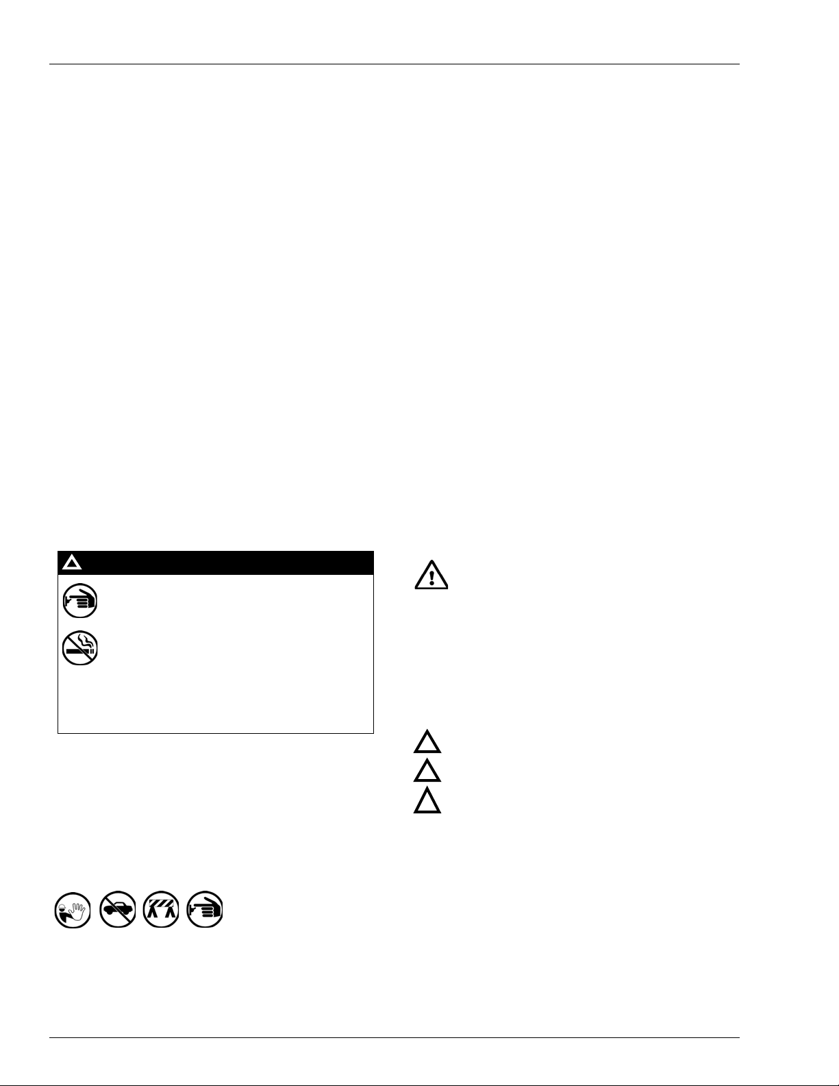
Important Safety Information
The EMERGENCY STOP, ALL STOP, and
PUMP STOP buttons at the cashier’s station
WILL NOT shut off electrical power to the
pump/dispenser. This means that even if you
activate these stops, fuel may continue to flow
uncontrolled.
You must use the TOTAL ELECTRICAL
SHUT-OFF in the case of an emergency and not
the console’s ALL STOP and PUMP STOP or
similar keys.
!
WARNING
!
Important Safety Information
Notes: 1) Save this Important Safety Information section
in a readily accessible location.
2) Although DEF is non-flammable, Diesel is
flammable. Therefore, for DEF cabinets that are
attached to Diesel dispensers, follow all the
notes in this section that pertain to flammable
fuels.
This section introduces the hazards and safety precautions
associated with installing, inspecting, maintaining or servicing
this product. Before performing any task on this product, read
this safety information and the applicable sections in this
manual, where additional hazards and safety precautions for
your task will be found. Fire, explosion, electrical shock or
pressure release could occur and cause death or serious injury,
if these safe service procedures are not followed.
Preliminary Precautions
You are working in a potentially dangerous environment of
flammable fuels, vapors, and high voltage or pressures. Only
trained or authorized individuals knowledgeable in the related
procedures should install, inspect, mainta in or service this
equipment.
Emergency Total Electrical Shut-Off
The first and most important information you must know is how
to stop all fuel flow to the pump/dispenser and island. Locate
the switch or circuit breakers that shut of f all p ower to all fueling
equipment, dispensing devices, and Submerged Turbine
Pumps (STPs).
Read the Manual
Read, understand and follow this manual and any other labels
or related materials supplied with this equipment. If you do not
understand a procedure, call a Gasboy Authorized Service
Contractor or call the Gasboy Service Center at
1-800-444-5529. It is imperative to your safety and the safety of
others to understand the procedures before beginning wo rk.
Follow the Regulations
Applicable information is available in National Fire Protection
Association (NFPA) 30A; Code for Motor Fuel Dispensing
Facilities and Repair Garages, NFPA 70; National Electrical
Code (NEC), Occupational Safety and Health Administration
(OSHA) regulations and federal, state, and local codes. All
these regulations must be followed. Failure to install, inspect,
maintain or service this equipment in accordance with these
codes, regulations and standards may lead to legal citations
with penalties or affect the safe use and operat ion of the
equipment.
Replacement Parts
Use only genuine Gasboy replacement parts and retrofit kits on
your pump/dispenser. Using parts other than genuine Gasboy
replacement parts could create a safety hazard and violate
local regulations.
Safety Symbols and Warning Words
This section provides important information about warn ing
symbols and boxes.
Alert Symbol
This safety alert symbol is used in this manual and on
warning labels to alert you to a precaution wh ich must be
followed to prevent potential personal safety hazards. Obey
safety directives that follow this symbol to avoid possible injury
Total Electrical Shut-Off Before Access
Any procedure that requires access to electrical co mponent s or
the electronics of the dispenser requires total electrical shut off
of that unit. Understand the function and location of this switch
or circuit breaker before inspecting, installing, maintaining, or
servicing Gasboy equipment.
Evacuating, Barricading and Shutting Off
Any procedure that requires access to the pump/dispenser or
STPs requires the following actions:
• An evacuation of all unauthorized persons and vehicles
from the work area
• Use of safety tape, cones or barricades at the affected
unit(s)
• A total electrical shut-off of the affected unit(s)
Page 8 MDE-4431C Gasboy ATC M05819K00X Kits Installation Manual · February 2013
or death.
Signal Words
These signal words used in this manual and on warning labels
tell you the seriousness of particular safety hazards. The
precautions below must be followed to prevent death, injury or
damage to the equipment:
DANGER: Alerts you to a hazard or unsafe practice
!
which will result in death or serious injury.
WARNING: Alerts you to a hazard or unsafe practice
!
that could result in death or serious injury.
CAUTION with Alert symbol: Designates a hazard or
!
unsafe practice which may result in minor injury.
CAUTION without Alert symbol: Designates a hazard
or unsafe practice which may result in property or
equipment damage.
Working With Fuels and Electrical Energy
Prevent Explosions and Fires
Fuels and their vapors will explode or burn, if ignited. Spilled or
leaking fuels cause vapors. Even filling customer tanks will
cause potentially dangerous vapors in the vicinity of the
dispenser or island.
DEF is non-flammable. Therefore, explosion and fire safety
warnings do not apply to DEF lines.
Page 9

Important Safety Information
The pump/dispenser contains a chemical known to the
State of California to cause cancer.
WARNING
!
The pump/dispenser contains a chemical known to the
State of California to ca use birth defects or other
reproductive harm.
WARNING
!
Gasoline/DEF ingested may cause
unconsciousness and burns to internal organs.
Do not induce vomiting. Keep airway open.
Oxygen may be needed at scene. Seek medical
advice immediately.
WARNING
!
WARNING
!
DEF generates ammonia gas at higher temperatures.
When opening enclosed panels, allow the unit to air out to
avoid breathing vapors.
If respiratory difficulties develop, move victim away from
source of exposure and into fresh air. If symptoms persist,
seek medical attention.
Gasoline/DEF spilled in eyes may cause burns to
eye tissue. Irrigate eyes with water for
approximately 15 minutes. Seek medical advice
immediately.
WARNING
!
WARNING
!
Gasoline inhaled may cause unconsciousness
and burns to lips, mouth and lungs. Keep airway
open. Seek medical advice immediately.
WARNING
!
Gasoline spilled on skin may cause burns.
Wash area thoroughly with clear water.
Seek medical advice immediately.
WARNING
!
DEF is mildly corrosive. Avoid contact with eyes, skin, and
clothing. Ensure that eyewash stations and safety s howers
are close to the work location. Seek medical advice
recommended treatment if DEF spills into eyes.
WARNING
!
No Open Fire
Open flames from matches, lighters, welding torches
or other sources can ignite fuels and their vapors.
No Sparks - No Smoking
Sparks from starting vehicles, starting or using power tools,
burning cigarettes, cigars or pipes can also ignite fuels and their
vapors. Static electricity, including an electrostatic charge on
your body, can cause a spark sufficient to ignite fuel vapors.
Every time you get out of a vehicle, touch the metal of your
vehicle, to discharge any electrostatic charge before you
approach the dispenser island.
Working Alone
It is highly recommended that someone who is capable of
rendering first aid be present during servicing. Familiarize
yourself with Cardiopulmonary Resuscitation (CPR) methods, if
you work with or around high voltages. This information is
available from the American Red Cross. Always advise the
station personnel about where you will be working, and caution
them not to activate power while you are working on the
equipment. Use the OSHA Lockout/Tagout procedures. If you
are not familiar with this requirement, refer to this information in
the service manual and OSHA documentation.
In an Emergency
Inform Emergency Personnel
Compile the following information and inform emergency
personnel:
• Location of accident (for example, address, front/bac k of
building, and so on)
• Nature of accident (for example, possible heart attack, run
over by car, burn s, and so on)
• Age of victim (for example, baby, teenager, middle-age,
elderly)
• Whether or not victim has received first aid (for example,
stopped bleeding by pressure, and so on)
• Whether or not a victim has vomited (for example, if
swallowed or inhaled something, and so on)
Working With Electricity Safely
Ensure that you use safe and established practices in working
with electrical devices. Poorly wired devices may cause a fire,
explosion or electrical shock. Ensure that grounding
connections are properly made. Take care that sealing devices
and compounds are in place. Ensure that you do not pinch
wires when replacing covers. Follow OSHA Lockout/Tagout
requirements. Station employees and service contractors need
to understand and comply with this program completely to
ensure safety while the equipment is down.
Hazardous Materials
Some materials present inside electronic enclosures may
present a health hazard if not handled correctly. Ensure that
you clean hands after handling equipment. Do not place any
equipment in the mouth.
MDE-4431C Gasboy ATC M05819K00X Kits Installation Manual · February 2013 Page 9
IMPORTANT: Oxygen may be needed at sc ene if g asoline has
been ingested or inhaled. Seek medical advice immediately.
Lockout/Tagout
Lockout/T agout covers servicing and maintenance of machines
and equipment in which the unexpected energization or s tart-up
of the machine(s) or equipment or release of stored energy
could cause injury to employees or personnel. Lockout/Tagout
applies to all mechanical, hydraulic, chemical or other energy,
but does not cover electrical hazards. Subpart S of 29 CFR Part
1910 - Electrical Hazards, 29 CFR Part 1910.333 contains
specific Lockout/Tagout provision for electrical hazards.
Page 10

Installing the Commercial Atlas (9800K) ATC Kits
Installing the Commercial Atlas (9800K) ATC Kits
Installing the ATC M05819K001 or M05819K003 Kit in Single Unit
Preparing for Installation
Request permission from the manager/owner to remove power from the unit and then remove
power using normal procedures. Observe the lockout/tagout safety procedures.
Ensure that you have the proper kit for the model dispenser to be retrofitted.
n
To install the ATC M05819K001 or M05819K003 Kit i
1 Using the proper key for the unit, unlock and remove the doors from both sides of the unit.
Note: Place doors in a safe place to pr
2 Remove the two screws securing the dial-enclosure assembly usi ng a P hillips screwdriver and
remove the assembly. Retain the screws for the replacing assembly after installation.
event damage or scratches.
Single Unit, proceed as follows:
3 Remove the two screws at side 1 of the unit (located above the display) using a Phillips
screwdriver, and pull the display cover forward.
Note: The cover pivots down in a horizontal position to allow access to the electr
of the unit. Save screws for replacing the assembly after installation.
onics section
Installing the ATC Kit
To install the ATC Kit, proceed as follows:
1 Locate the Polycase Box (LP-70) with SK449C mounted inside the M05819K001 Kit.
~OR~
Locate the Polycase Box (LP-70) with Printed Circuit Board [PC
M05819K003 Kit.
2 Remove the four mounting screws securing the cover and remove the cover from the box.
Retain the screws and cover for reinstalling later.
B (28017)] mounted inside
Page 10 MDE-4431C Gasboy ATC M05819K00X Kits Installation Manual · February 2013
Page 11

Installing the Commercial Atlas (9800K) ATC Kits
About
1-1/2 inches
Clearance
3 Peel the protective cover from the Mounting Sponge (on the back of the Polycase Box) and
mount the box as shown in Figure 3. Mount about 1-1/2 inches up from shelf (1-1/2-inch
clearance under the shelf).
Figure 3: Mounting the Polycase Box (LP-70)
4 Locate the two Washers [N23746-01 (mounted to shelf with two screws)] on the two shelves
creating the air gap.
Note: The lower washer location also has a Ga
5 Remove the two screws from each washer and remove the washers. Retain the gasket and
sket (N23761-04).
screws for use later.
6 Locate the two Conduit Seal Washers (N23760-07) provided in the kit.
7 Place the two Conduit Seal Washers (N23760-07) where the two Washers (N23746-01) were
mounted and place the gasket (saved in step 5) under the conduit seal washer on the lower
shelf. Secure washers with screws that were
8 Locate the Dual Intrinsic Safety (IS) Barrier (27913) and Sing le Prob e Conn ecto r Assembly
removed in step 5.
(212AY04) provided in the kit. Remove the nut and washer from the mounting stud on the IS
barrier and slide them off the wires. Retain the nut and washer for use later.
MDE-4431C Gasboy ATC M05819K00X Kits Installation Manual · February 2013 Page 11
Page 12

Installing the Commercial Atlas (9800K) ATC Kits
IS Barrier
IS Barrier Mounting
Stud through Air Gap
Lower Conduit Seal
Washer and Gasket
Upper Conduit
Seal Washer
Probe Connector
Probe Connector
Assembly
IS Barrier
Mounting Stud
9 Feed the wires extending from the IS Barrier Mounting S tud through the Conduit Seal Washer
on each shelf as shown in Figure 4 and place the mounting stud through the holes.
Figure 4: Mounting the IS Barrier on the Shelf
10 Place the wires extending from the mounting stud through the mounting hole in the single
Probe Connector Assembly and place the assembly up on the stud (under the shelf as shown in
Figure 5).
Figure 5: Probe Connector Assembly and IS Barrier Stud Mounting (Under the Shelf)
11 Place the washer and nut over the wires and turn nut onto the stud securing the IS Barrier and
Probe Connector. Tighten snugly but do not overtighten.
Page 12 MDE-4431C Gasboy ATC M05819K00X Kits Installation Manual · February 2013
Page 13

Installing the Commercial Atlas (9800K) ATC Kits
Pulser 1 and
Handles Jacks
Pulser 2 Jack
LCD Display
Jack
LCD Display
Jack
Pulser 1 and
Handles Jacks
Pulser 2 Jack
(i)
CPU PCB Assembly with Connections
(ii)
CPU PCB Assembly without Connections
12 On the CPU PCB Assembly (see Figure 6), disconnect the Connectors connected to the
Pulser 1 and Handles jacks.
Figure 6: CPU PCB Assembly
MDE-4431C Gasboy ATC M05819K00X Kits Installation Manual · February 2013 Page 13
Page 14

Installing the Commercial Atlas (9800K) ATC Kits
Assembly (461A2)
Pulser 1, Handles,
and Pulser 2
Connectors
LCD Display Connector
Assembly (460A4)
13 Locate the Circuit Board Assembly (461A2) provided in the kit (for identification,
see Figure 1 on page 5). Connect the assembly to the jacks labeled Pulser 1, Handles, and
Pulser
Figure 7: CPU with New Connections
2 at the CPU Printed Circuit Assembly [PCA (see Figure 7)].
14 Reconnect the Connectors disconnected in step 12 on page 13 to the Circuit Board Assembly
[461A2 (directly above the Pulser 1 and Handles Connectors)].
15 At the CPU PCA (see Figure 6 on page 13), disconnect the Connector connected to the LCD
Display jack.
16 Locate the Circuit Board Assembly (460A4) provided in the kit (for identification, see
Figure 1 on page 5). Connect the assembly to the jack labeled LCD Display on the CPU PCA.
17 Reconnect the Connector disconnected in step 15 to the Circuit Board Assembly (460A4) J1
jack (in center of the board).
18 Locate the Pulser/Handle Ribbon Cable (W284) provided in the kit (for identification, see
Figure 1 on page 5).
Page 14 MDE-4431C Gasboy ATC M05819K00X Kits Installation Manual · February 2013
Page 15

Installing the Commercial Atlas (9800K) ATC Kits
PCB (461A2)
P1
P2
P5
P6/P7
DIP
Switches
19 Connect one end of the Cable (W284) to P1 on the Board [461A2 (see Figure 8)] and the other
end to P2 in the Polycase Box [LP-70 (see Figure 9)].
Figure 8: Circuit Board (461A2) with Connections
Figure 9: Polycase Box (LP-70) Showing Connections
20 Locate the Display Adapter Harness (W283) provided in the kit (for identification, see
Figure 1 on page 5).
MDE-4431C Gasboy ATC M05819K00X Kits Installation Manual · February 2013 Page 15
Page 16

Installing the Commercial Atlas (9800K) ATC Kits
J1
J4 Display Adapter
Connector (W283)
Circuit Board
Assembly (460A4)
21 Connect one Connector on the harness (both are the same) to J4 on the Circuit Board
Assembly (460A4) and the other Connector to P6/P7 in the Polycase Box [LP-70 (see
Figure 10)].
Figure 10: Circuit Board (460A4) in Place with Connections Made
22 Locate the Two-wire Harness (W171) for IS barrier provided in the kit.
23 Place the Connector on the harness on P5 in the Polycase Box [LP-70 (see Figure 9 on
page 15)].
24 Using two of the crimp splices, connect the wires of the harness to the wires extending from
the top of the IS barrier. Match color codes.
25 Cap the end of the green wire from the IS Safety Barrier, using a Cap (0M0205) or an
appropriate size wire nut (these are not part of the kit).
26 Connect the ground wire (the wire with eyelet connector) to the nearest true ground.
27 Disconnect the cable going to P6 Connector of the Pump CPU Board.
28 Connect the cable that was disconnected in step 27 to P9 Connector in the Polycase Box
(LP-70).
Note: If the user wants to be able to display
electronic totals, another Cable (M05119A001)
must be installed and connected to the P6 Connector on the Pump CPU Board.
Page 16 MDE-4431C Gasboy ATC M05819K00X Kits Installation Manual · February 2013
Page 17

Installing the Commercial Atlas (9800K) ATC Kits
29 In the Polycase Box (LP-70), locate the DIP Switches shown in Figure 9 on page 15 and set
the switches for the proper unit as shown in the fol
DIP Switch Settings
Switch
Number
1 Product 1 ON for Diesel, OFF for Gasoline ON for Diesel, OFF for Gasoline
2 Product 2 ON for Diesel, OFF for Gasoline ON for Diesel, OFF for Gasoline
3 Not used N/A N/A
4 Unit of Measure N/A ON for Liters, OFF for Gallons
5 Pulser Multiplier ON for 9850 and 9850K, OFF for
6 Number of
7 Pulser Adder ON for 9840 ON for 9840K
8 ATC ON for ATC ON, OFF for ATC OFF ON for ATC ON, OFF for ATC OFF
Switch
nction
Fu
Probes
Settings for Existing and Model
9850K
9853
9852/
ON fo
r two (2) probes, OFF for one (1)
probe
lowing table.
Settings for Models
9840K, 9852K, 9853K
N/A
ON for two (
probe
2) probes, OFF for one (1)
30 Remount the Polycase Box (LP-70) cover removed in step 1 on page 10.
31 Using two of the crimp splices, connect the two yellow wires extending from the bottom of the
IS Barrier Mounting Stud to the two blue wires attached to the Single Probe Connector
Assembly.
32 Cap the end of the two green wires extending from the bottom of the IS barrier, using two
Caps (0M0205) or suitable size wire nuts (these are not part of the kit).
33 Locate the following parts provided in the kit (for parts identification, see Figure 1 on page 5):
• Probe Assembly (W199)
• Thermowell (BC407)
• Thermowell Plug (235-C)
• Adapter (BC546)
MDE-4431C Gasboy ATC M05819K00X Kits Installation Manual · February 2013 Page 17
Page 18

Installing the Commercial Atlas (9800K) ATC Kits
Probe Assembly
Holes plugged when Probe is not
installed
Adapter
Thermowell Plug
Thermowell
When applying SAF-T-LOK® TPS Sealant on threads, leave the two threads that
enter the hole first free of sealant to prevent the sealant from entering, and
possibly damaging or inhibiting proper operation of the unit.
CAUTION
34 Under the shelf (where the IS Barrier Stud is secured), locate the two plugs in the hydraulic
coupling (see Figure 11).
Figure 11: Hydraulic Coupling (Probe Assembly Mounting Location)
35
Remove the two plugs using an appropriate size Allen-wrench.
36 Coat the Thermowell Threads (BC407) with SAF-T-LOK TPS Sealant and threads into one of
the holes where the plugs were removed in step 35 (see Figure 11).
37 Tighten the Thermowell using a proper size wrench and place the Thermowell Plug (235-C)
into the Thermowell.
38 Coat the threads of the Adapter (BC546) with SAF-T-LOK TPS Sealant and turn it into the
other hole where the plugs were removed in step 35 (see Figure 11).
39 Coat the threads of the Probe Assembly (W199) with SAF-T -LOK TPS S ealant and turn it into
Page 18 MDE-4431C Gasboy ATC M05819K00X Kits Installation Manual · February 2013
the Adapter (BC546) mounted in step 38 on page 26.
Page 19

Installing the Commercial Atlas (9800K) ATC Kits
Ensure the threads on the Thermowell, Adapter, and Probe Assembly are properly
coated with the SAF-T-LOK TPS Sealant and tightened to prevent leaks.
CAUTION
40
Tighten both the Adapter and Probe using an appropriate size wrench.
41 Connect the other end of the Probe to Probe Connector Assembly in the connector labeled “1”
(for Probe Connector Assembly location, see Figure 5 on page 12).
42 Go to “Completing Installation” on page 27 in this manual.
Installing the ATC M05819K002 or M05819K004 Kit in Twin Unit
Preparing for Installation
Request permission from the manager/owner to remove power from the unit and then remove
power using normal procedures. Observe the lockout/tagout safety procedures.
Ensure that you have the proper kit for the model dispenser to be retrofitted.
1 Unlock and remove the doors from both sides of the unit using proper key for the unit. Place
doors in a safe place to prevent damage or scratches.
2 Remove the two screws securing the dial enclosure assembly using a Phillips screwdriver and
remove the assembly. Retain the screws for replacing assembly after installation.
3 Loosen the two screws (one on each side of the display cover) using a Phillips screwdriver, at
side 1 of the unit. Spring the screw holders and screws out from the display cover and pull the
display cover forward.
Note: The cover pivots down in a horizontal position allowing access to the electronics
section
of the unit.
Installing ATC Kit
1 Locate the Polycase Box (LP-70) with PCB (SK449C) mounted inside, in the M05819K003
Kit.
~OR~
Locate the Polycase Box (LP-70) with PCB (2801
2 Remove the four mounting screws securing the cover and remove the cover from the box.
Retain screws and cover for reinstalling later.
7) mounted inside, in the M05819K004 Kit.
MDE-4431C Gasboy ATC M05819K00X Kits Installation Manual · February 2013 Page 19
Page 20

Installing the Commercial Atlas (9800K) ATC Kits
About
1-1/2 inches
Clearance
3 Peel the protective cover from the Mounting Sponge (on the back of the Polycase Box) and
mount the box as shown in Figure 12. Mount about 1-1/2 inches up from shelf.
Figure 12: Mounting the Polycase Box (LP-70)
4 On the two shelves creating the air gap, locate the two washers [N23746-01 (mounted to shelf
with two screws)].
Note: The lower washer location als o has a Gasket (N23761-04).
5 Remove the two screws from each washer and remove the washers. Retain the gasket and
screws to use later.
6 Locate the two Conduit Seal Washers (N23760-07) provided in the kit.
7 Place the two conduit seal washers where the two Washers (N23746-01) were mounted, place
the gasket (saved in step 5) under the conduit seal washer on the lower shelf, and secure
washers with screws removed in step 5.
8 Locate the Single IS Barrier (27913) and Dual Probe Connector Assembly (212AY05)
provided in the kit. Remove the nut and washer from the mounting stud on the IS Barrier and
slide them off the wires. Retain the nut and washer to use later.
Page 20 MDE-4431C Gasboy ATC M05819K00X Kits Installation Manual · February 2013
Page 21

Installing the Commercial Atlas (9800K) ATC Kits
IS Barrier
IS Barrier Mounting Stud
through Air Gap
Lower Conduit Seal
Washer and Gasket
Upper Conduit
Seal Washer
Probe Connector
Probe Connector
Assembly
IS Barrier Mounting Stud
9 Feed the wires extending from the IS Barrier Mounting Stud through the hole in the shelf as
shown in Figure 13 and place the mounting stud through the hole.
Figure 13: Mounting the IS Barrier on the Shelf
10 Place the wires extending from the mounting stud through the mounting hole in the Dual
Probe Connector Assembly. Place the Connector Assembly up on the stud [under the shelf
(see Figure 14)].
Figure 14: Probe Connector Assembly and IS Barrier Stud Mounting (Under the Shelf)
Note: The probe connection to the Probe Connector Assembly shown is for a single unit. The
dual unit has two probe connectors connected to the assembly.
11 Place the washer and nut over the wires and turn nut onto the stud securing the IS Barrier and
Probe Connector. Tighten snugly but do not overtighten.
MDE-4431C Gasboy ATC M05819K00X Kits Installation Manual · February 2013 Page 21
Page 22

Installing the Commercial Atlas (9800K) ATC Kits
Pulser 1 and
Handles Jacks
Pulser 2 Jack
LCD Display
Jack
LCD Display
Jack
Pulser 1 and
Handles Jacks
Pulser 2 Jack
(i)
(ii)
CPU PCB Assembly with Connections
CPU PCB Assembly without Connections
12 At the CPU PCA (see Figure 15), disconnect the Connector connected to the Pulser 1,
Handles, and Pulser 2 jacks.
Figure 15: CPU PCB Assembly
13 Locate the Circuit Board Assembly (461A2) provided in the kit (for identification, see
Figure 1 on page 5). Connect the assembly to the jacks labeled Pulser 1, Ha
ndles, and Pulser 2
at the CPU PCA.
14 Reconnect the Connector removed in step 8 on page 20 to the Circuit Board Assembly [461A2
(directly above the Pulser 1, Handles, and Pulser 2 Connectors)].
Page 22 MDE-4431C Gasboy ATC M05819K00X Kits Installation Manual · February 2013
Page 23

Installing the Commercial Atlas (9800K) ATC Kits
Ensure the Cables are connected to the Connectors as follows:
• From P1 of 461A2 to P2 of LP-70 Polycase Box.
• From P8 of 461A2 to P3 of LP-70 Polycase Box.
IMPORTANT INFORMATION
PCB (461A2)
P1
P8
15 At the CPU PCA (see Figure 15 on page 22), disconnect th e Connector connected to the LCD
Display jack.
16 Locate the Circuit Board Assembly (460A4) provided in the kit (for identification, see
Figure 1 on page 5). Conne
17 Reconnect the Connector removed in step 11 on page 21 to the Circuit Board Assembly
ct the assembly to the jack labeled LCD Display at the CPU PCA.
(460A4) J1 jack (in center of board).
18 Locate the two Pulser/Handle Ribbon Cables (W284) provided in the kit (for identification,
see Figure 1 on page 5).
19 Connect one end of one Cable (W284) to P1 on the Board [461A2 (see Figure 16)] and the
other end to P2 in the Polycase Box [LP-70 (see Figure 17 on
20 Connect one end of the second Cable (W284) to P8 on the Board [461A2 (see Figure 16 )] and
the other end to P3 in the Polycase Box [LP-70 (see
Figure 17 on page 24)].
page 24)].
Figure 16: Circuit Board (461A2) with Connections
MDE-4431C Gasboy ATC M05819K00X Kits Installation Manual · February 2013 Page 23
Page 24

Installing the Commercial Atlas (9800K) ATC Kits
P2
P5
P6/P7
DIP Switches
P3
J1
J4 Display Adapter
Connector (W283)
Circuit Board
Assembly (460A4)
Figure 17: Polycase Box (LP-70) Showing Connections
21 Locate the Display Adapter harness (W283) provided in the kit (for identification, see Figure 1
on page 5).
22 Connect one Connector on the harness (both are the same) to J4 on the Circuit Board
Assembly [460A4 (see Figure 18)] and the other Connector to P6/P7 in the Polyc
[LP-70 (see Figure 17)].
ase Box
Figure 18: Circuit Board (460A4) in Place with Connections Made
23 Locate the Three-wire Harness (9W172) for IS Barrier provided in the kit.
24 Place the Connector on the harness on P5 in the Polycase Box [LP-70 (see Figure 17)].
25 Using three of the crimp splices, connect the wires of the harness to the wires extending from
the top of the IS barrier. Match color codes.
26 Connect the ground wire (the wire with eyelet connector) to the nearest true ground.
Page 24 MDE-4431C Gasboy ATC M05819K00X Kits Installation Manual · February 2013
Page 25

Installing the Commercial Atlas (9800K) ATC Kits
27 Disconnect the cable going to P6 Connector of the Pump CPU Board.
28 Connect the cable that was disconnected in step 27 to P9 Connector in the Polycase Box
(LP-70).
Note: If the user wants to be able to display
electronic totals, another Cable (M05119A001)
must be installed and connected to the P6 Connector on the Pump CPU Board.
29 In the Polycase Box (LP-70), locate the DIP switches shown in Figure 17 on page 24 and set
the switches for the proper unit as shown in the fol
DIP Switch Settings
Switch
Number
1 Product 1 ON for Diesel,
2 Product 2 ON for Diesel,
3 Not used N/A N/A
4 Unit of Measure N/A ON for Liters,
5 Pulser Multiplier ON for 9850 and 9850K,
6 Number of
7 Pulser Adder ON for 9840 ON for 9840K
8 ATC ON for ATC ON,
Switch
nction
Fu
Probes
Settings for Existing and
Model 9850K
OFF for Gasoline
OFF for Gasoline
OFF for 9852/9853
ON for two (2) probes,
OFF for one (1) probe
OFF for ATC OFF
lowing table.
Settings for Models
9840K, 9852K, 9853K
ON for Diesel,
OFF for Gasoline
ON for Diesel,
OFF for Gasoline
OFF for Gallons
N/A
ON for two (2) probes,
F for one (1
OF
ON for ATC ON,
OFF for ATC OFF
) probe
30 Remount the Polycase Box (LP-70) cover removed in step 1 on page 19.
31 Using two of the crimp splices, connect the two green wires extending from the bottom of the
IS Safety Barrier Mounting Stud to the two green wires attached to the Dual Probe Connector
Assembly.
32 Using two of the crimp splices, connect the two yellow wires extending from the bottom of the
Intrinsic Safety Barrier Mounting Stud to the two yellow wires attached to the Dual Probe
Connector Assembly.
33 Locate the following parts provided in the kit (for parts identification, see Figure 1 on page 5):
• Probe Assembly [W199 (2)]
• Thermowell [BC407(2)]
• Thermowell Plug [235-C (2)]
• Adapter [BC546 (2)]
MDE-4431C Gasboy ATC M05819K00X Kits Installation Manual · February 2013 Page 25
Page 26

Installing the Commercial Atlas (9800K) ATC Kits
Probe Assembly
Holes plugged when
Probe is not installed
Adapter
Thermowell Plug
Thermowell
When applying SAF-T-LOK TPS Sealant on threads, leave the two threads that
enter the hole first free of sealant to prevent the sealant from entering, and
possibly damaging or inhibiting proper operation of the unit.
CAUTION
34 Under the shelf (where the IS Barrier is mounted), locate the two plugs in the hydraulic
coupling toward the right side of the unit (see Figure 19).
Figure 19: Hydraulic Coupling (Probe Assembly Mounting Location)
35 Remove the two plugs using an appropriate size Allen-wrench.
36 Coat the Thermowell Threads (BC407) using SAF-T-LOK TPS Sealant and thread into one of
the holes where the plugs were removed in step 35 (see Figure 19).
37 Tighten the Thermowell using a proper size wren ch and place the 235-C Thermowell Plug into
the Thermowell.
38 Coat the threads of the Adapter (BC546) with SAF-T-LOK TPS Sealant and turn it into the
other hole where the plugs were removed (see Figure 19).
39 Coat the threads of the Probe Assembly (W199) with SAF-T -LOK TPS S ealant and turn it into
the Adapter (BC546) mounted in step 38.
Page 26 MDE-4431C Gasboy ATC M05819K00X Kits Installation Manual · February 2013
Page 27

Installing the Commercial Atlas (9800K) ATC Kits
Ensure that the threads on the Thermowell, Adapter, and Probe Assembly are
properly coated with the SAF-T-LOK TPS Sealant and tightened properly to
prevent leaks.
CAUTION
40
Tighten both the adapter and probe using the proper size wrench.
41 Connect the other end (Connector) of the Probe to Probe Connector Assembly in the connector
labeled “1”.
42 Locate the other two plugs in the hydraulic coupling toward the left side of the unit (see
Figure 19 on page 26).
43 Repeat steps 28 through 33 on page 25 to mount the second Probe Assembly.
44 Connect the Connector end of the second Probe to Probe Connector Assembly in the
connector labeled “2”.
45 Go to “Completing Installation” to complete the installation procedure.
Completing Installation
1 Dress the cablings by placing them in existing cable ties. Ensure the cables do not create any
obstruction to operation, access, or servicing.
2 Test the ATCs to determine that they are functioning properly.
This will involve running transactions and using the totalizer display (for more information,
refer to “Appendix: To
3 After determining that the ATCs are functioning properly:
• using screws saved, remount the dial enclosure assemblies.
• remount the doors on both sides of the unit.
• secure doors with the keylocks.
4 Inform the manager/owner that the unit can be returned back to service.
talizer Display Information” on page 28).
MDE-4431C Gasboy ATC M05819K00X Kits Installation Manual · February 2013 Page 27
Page 28

Appendix: Totalizer Display Information
0023.43
0 23.2
189.2
1.30
842 .2
Appendix: Totalizer Display Information
By activating the magnet located at the opposite side of the totalizer, following information
will appear on the display.
Information Type Definition Example of Display
Volume Displays uncompensated volume.
Probe Temperature Displays probe temperature (in Celsius only).
Flow Rate Displays flow rate [in Liters Per Minute (LPM only)].
Software Version Displays software version number.
ATC Status Displays ATC status.
Leftmost digits (842) are error indicators, which are blank
when the
8 = tempera
4
2 = exceptional reset detected
Rightmost digit (2
comp
dispensed.
0 = tempera
1 = product is g
2 = product is d
corresponding error condition is not active.
ture probe fault detected
= pulser error occurred
) indicates whether temperature
ensation is enabled, and if so,
ture compensation disabled
asoline and compensation enabled
iesel and compensation enabled
what product is being
Allen® is a registered trademark of Industrial Fasteners, Inc. Atlas™ is a trademark of Gasboy Inc. Phillips® is a registered trademark of
Phillips Screw Company. Polycase
Chemical Corporation. Teflon
®
is a registered trademark of ECP Corporation. SAF-T-LOK® is a registered trademark of SAF-T-LOK
®
is a registered trademark of E.I. DuPont de Nemours and Company.
© 2013 GASBOY
7300 West Friendly Avenue · Post Office Box 22087
Greensboro, North Carolina 27420
Phone (800) 444-5529 · http://www.gasboy.com · Printed in the U.S.A.
MDE-4431C Gasboy ATC M05819K00X Kits Installation Manual · February 2013
 Loading...