

Page 1
FIELD INSTALLATION OF AN ISLANDER INTERNAL MODEM KIT
When using these instructions for replacement of a defective internal modem, disregard all steps that detail the mounting of
the modem kit hardware.
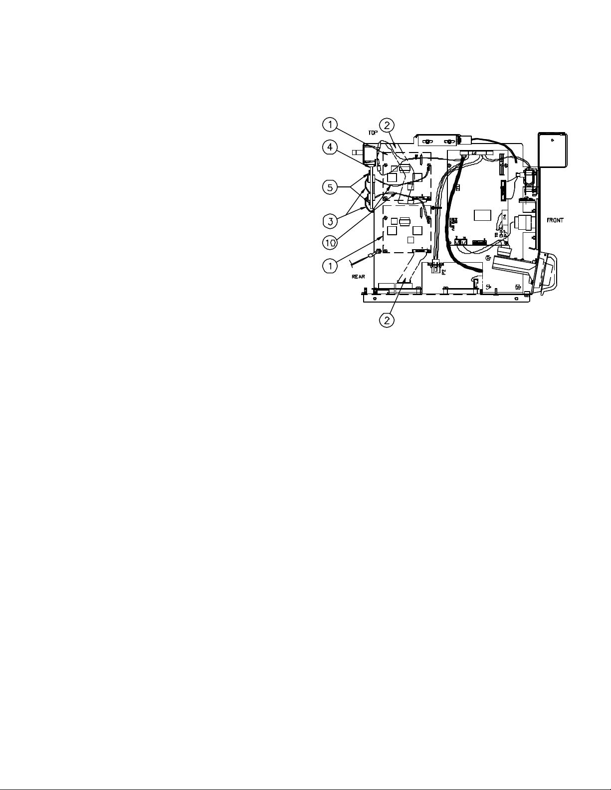
The Islander Internal Modem Kit should contain the following parts (shown installed):
Item Part No. Qty Description
1 C07123 1 Modem, 33600 Internal (C07197 kit
only)
C07122 1 Modem, 2400 internal (C06667 kit
only)
2 C05738 1 Cable assy, 20-pos ribbon
3 C05737 1 Cable assy, phone line
4 C35475 1 Bracket assy, phone jack
5 C08759 6 Screw, 6-32 x 3/8 Phillips head
7 C08460 4 Standoff, M/F #6-32
8 C08279 4 Standoff, F/F #6-32 x 7/16
9 C01166 4 Washer,-std spring lock
10 C05356 1 Cable assy, phone dual
11 C02207 1 Clamp, ribbon cable
12 C35554 1 Instruction sheet
ISLANDER I PROCEDURE
1. Unlock and open the rear door of the Islander head.
2. Turn off the AC power switch located to the lower right in the rear of the head.
3. Remove the hood of the unit from the head. This is done by removing the four external screws (two each side) which
secure the hood to the Islander head. Also remove the two internal wing nuts which secure the top of the hood to the
hood support bracket.
4. On the left partition, from the rear of the unit, locate the position of the holes for the modem standoffs. Place a washer
C01166 on each standoff C08460 then thread them into the inside of the left partition. Repeat this procedure until all
four standoffs are mounted to the inside of the plate.
5. Slide the R-11 jack of phone line cable assembly C05737 onto the bracket assy C35475, by holding the bracket so the
two slots are to the left and the bend is toward the rear. Then slide the R-11 jack into the bottom slot so the green and
red wire go toward the rear. Mount the bracket on the rear of the left panel near the top, secure it with two Phillips
screws C08759.
6. If replacing a modem, remove the old modem. Install new modem C07122 or C07123 by positioning it so the 20-
position connector is on the bottom of the modem. Align the holes on the modem with standoffs and secure with four
C08759 Phillips screws.
7. Attach the phone line cable assembly C05737 to the 2-position connector of the modem so the green wire of the cable
faces the rear of the unit.
8. Attach one end of the 20-position ribbon cable C05738 to the 20-position modem connector so that pin 1 (the red or
dark blue edge of the cable) faces the front of the unit. Plug the other end of the cable into P8 of the Site
Communications I/O PCB. Refer to your Site Controller I and Islander Start-Up Manual, C01900 for proper jumper
settings on the Site Communication I/O PCB. Set the correct baud rate between 300 and 2400 baud on the Site
Controller I remote port.
9. Attach the phone dual (6P/4W ) cable assembly C05356 from the phone line cable assembly to the incoming phone jack
in the base of the Islander pedestal.
10. Turn on the AC power switch.
11. Test the modem and verify its operation. After testing the unit turn off the AC power switch.
C35554 Rev. 0202
Page 2

12. Replace the hood of the unit and fasten it with the four external screws and two internal wing nuts removed previously.
13. Turn on the AC power switch.
14. Close and lock the rear door of the Islander head.
ISLANDER II PROCEDURE
1. Unlock and open the rear door of the Islander II head.
2. Turn off the AC power switch located to the lower right in the rear of the head.
3. Remove the hood of the unit from the head. This is done by removing the four external screws (two each side) which
secure the hood to the Islander head. Also remove the two internal wing nuts which secure the top of the hood to the
hood support bracket.
4. On the left partition, from the rear of the unit, locate the position of the threads for the modem standoffs. Thread the four
C08279 standoffs onto the outside of the left partition. (The bottom four threads are for answer modems and top four
threads are for network modems.)
5. Slide the R-11 jack of C05737 onto the bracket assembly C35475, by holding the bracket so the two slots are to the left
and the bend is toward the rear. Then slide the R-11 jack into the bottom slot so the green and red wire go toward the
rear. Mount the bracket on the rear of the left panel near the top, secure it with two C08759 Phillips screws.
6. Install new modem C07122 or C07123 by positioning it so the 20-position connector is on the bottom of the modem.
Align the holes on the modem with standoffs and secure with four C08759 Phillips screws.
7. Attach the phone line cable assembly C05737 to the 2-position connector of the modem so the green wire of the cable
faces the rear of the unit.
8. If you are installing a modem for Bank Network use, go to Step 9. Attach one end of the 20-position ribbon cable
C05738 to the 20-position modem connector so that pin 1 (the red or dark blue edge of the cable) faces the front of the
unit. Plug the other end of the cable plug into P8 of the horizontally-mounted Site Communications I/O PCB. Refer to
your Site Controller II and Islander II Start-Up Manual (C01665) for proper jumper settings and baud rates on the Site
Communication I/O PCB and Site Controller II CPU. Set the correct baud rate on the Site Controller II CPU remote port.
Go to Step 10.
9. Attach one end of the 20-position ribbon cable C05738 to the 20-position modem connector so that pin 1 (the red or
dark blue edge of the cable) faces the front of the unit. Plug the other end of the cable plug into P7 of the vertically-
mounted Site Communications I/O PCB. Refer to your Site Controller II and Islander II Start-Up Manual (C01665) for
proper jumper settings on the Site Communication I/O PCB and Islander II CPU. In SYS_PAR, set the Host handler
Channel to 1. Refer to your Network manual for all other network configurations.
10. Attach the phone dual (6P/4W ) cable assembly C05356 from the phone line cable assembly to the incoming phone jack
in the base of the Islander pedestal.
11. Turn on the AC power switch.
12. Test the modem and verify its operation. After testing the unit turn off the AC power switch.
13. Replace the hood of the unit and fasten it with the four external screws and two internal wing nuts removed previously.
14. Turn on the AC power switch.
15. Close and lock the rear door of the Islander II head.
C35554 Rev. 0202
 Loading...