


Gilbarco® Global Pumping Unit
Operation and Service Manual
MDE-4447A

Computer Programs and Documentation
Federal Communications Commission (FCC) Warning
All Gilbarco Inc. and/or Veeder Root Company computer programs (including software on diskettes and within memory chips) and documentation are copyrighted by, and shall
remain the property of, Gilbarco Inc. and/or Veeder Root Company. Such computer programs and documents may also contain trade secret information. The duplication, disclosure,
modification, or unauthorized use of computer programs or documentation is strictly prohibited, unless otherwise licensed by Gilbarco Inc. and/or Veeder Root Company.
This equipment has been tested and found to comply with the limits for a Class A digital device pursuant to Part 15 of the FCC Rules. These limits are designed to provide
reasonable protection against harmful interference when the equipment is operated in a commercial environment. This equipment generates, uses, and can radiate radio frequency
energy, and if not installed and used in accordance with the instruction manual, may cause harmful interference to radio communications. Operation of this equipment in a residential
area is likely to cause harmful interference in which case the user will be re quired to correct the inte rference at his own exp ense. Changes or modifications not expressly approved by
the manufacturer could void the user’s authority to operate this equipment.
Approvals
Gilbarco is an ISO 9001:2000 registe red company.
Underwriters Laboratories (UL):
U L File# Products listed with U L
MH1941
MH8467 Transac System 1000 and PAM 1000
All Gilbarco pumps and dispensers that bear
the UL listing mark.
New York City Fire Department (NYFD):
NYFD C of A # Product
4805
4986 Encore and Eclipse
The Advantage Series and
Legacy Series
E105106 Dell DH M M i n i t o w e r
E165027 G-SITE a n d P a s s p o r t S y s t e m s
National Conference of Weights and Measures (NCWM) - Certificate of Conformance (CoC):
Gilbarco pumps and dispensers are evaluated by NCWM under the National Type Evaluation Program (NTEP). NCWM has issued the following CoC:
CoC# Product Model # CoC# Product Model # CoC# Product Model #
02-019 Encore Nxx 02-026 H111B Series AC, RAC 02-034 External Mount CRIND CECXXXXXXX
02-020 Eclipse Exx
02-021
T-12C Console PA0188, RA0188 Fixed Blender
T-12C Console PA0203, RA0203 Dispenser - Low Profile AR, RAR
02-022 T-12G Console PA0180, RA0180
T-15 Console PA0189 Outdoor Card Q11891 G-SITE Keyboard PA0304
02-023
T-15 Controller C2 PA0211 02-029 CRIND — G-SITE Mini Tower PA0301
02-027
02-028
T-15 Controller PA0190
ProBlender AU, RAU TS-1000 Controller PA0241 G-SITE Printer (Citizen) PA0308
02-024
Precision Blender AE, RAE Distribution Box PA0242 02-038 C+ Meter T19976
Dispenser - Standard AK, RAK Micro-T Console PA0250 02-039 Passport PA0324
02-030
Dispenser - Low Profile AL, RAL Meter - EC Series PA024EC10 02-040 Ecometer T20453
Fixed Blender AP, RAF VaporVac Kits CV
02-025
Meter - C Series PA024NC10 02-031 The Advantage Series Bxx, RBxx
Meter - C Series PA024TC10 02-032 Trimline Series AA, RAA
Salesmaker ProBlender AB, RAB 02-033 Meter - C Series PA024XC10
99-165 Salesm a k e r S e r i e s 2 / 2 H /4 /4A AM MPD-A3 Series AD, RAD
MPD-1 Series AN, RAN 02-035 Dimension Dxx
AF, RAF, AG,
RAG
Indoor Card Q11640 G-SITE Distribution Box PA0306
TS-1000 Console PA0240 G-SITE Monitor PA0303
California Air Resources Board (CARB):
Executive Order # Product
G-70-52-AM Balance Vapor Recovery
G-70-150-AE VaporVac
02-036 Legacy Jxxx
G-SITE Printer (Epson) PA0307
02-037
Patents
Gilbarco Inc. products are manufactured or sold under one or more of the following US patents:
Dispensers
4,566,504 4,556,927 4,570,686 4,687,033 4,728,788 4,748,846 4,799,940 4,805,453 4,876,653 4,890,210 4,913,813 4,930,655 4,934,565 4,938,054
4,938,251 4,939,730 4,967,366 4,986,445 5,040,577 5,098,179 5,134,548 5,156,199 5,269,353 5,228,084 5,325,706 5,345,979 5,355,915 5,363,988
5,384,850 5,407,115 5,417,256 5,448,638 5,450,883 5,464,466 5,501,246 5,535,130 5,542,458 5,543,849 5,546,981 5,557,084 5,571,310 5,602,745
5,626,649 5,630,528 5,708,580 5,719,779 5,719,781 5,720,325 5,724,067 5,734,851 5,755,854 5,782,275 5,794,667 5,798,931 5,803,136 5,843,212
5,857,500 5,868,179 5,871,651 5,890,520 5,954,080 5,956,259 5,969,691 5,971,042 5,979,705 5,980,090 6,026,866 6,052,629 6,073,840 6,078,888
6,078,896 6,082,415 6,085,775 6,087,954 6,089,284 6,092,410 6,098,879 6,102,085 6,109,477 6,112,134 6,113,039 6,116,505 6,119,110 6,123,118
6,149,033 6,167,923 6,176,421 6,184,846 6,185,307 6,185,893 6,196,065 6,227,227 6,244,310 6,250,151 6,253,779 6,263,319 6,275,746 6,296,148
6,302,165 6,313,737 6,325,112 6,326,934 6,336,479 6,338,369 6,347,649 6,352,176 6,357,493 6,360,137 6,363,299 6,364,206 6,380,853 6,381,514
6,386,246 6,418,983 6,421,616 6,422,464 6,431,226 6,438,452 6,460,579 6,463,389 6,466,842 6,470,233 6,493,440 6,499,516 6,505,134 6,522,947
6,523,744 6,529,800 6,532,999 6,535,726 6,546,882 6,571,151 6,571,201 6,573,884 6,574,603 6,578,145 6,618,362 6,644,360 6,681,814 6,685,089
6,690,275 6,697,705 6,704,774 6,708,797 6,710,701 6,712,101 6,721,669 6,736,313 6,741,909 6,745,104 6,761,190 6,763,974 6,766,949 RE35,238
D262,971 D265,092 D306,719 D309,144 D316,471 D413,124 D413,311 D413,336 D413,337 D413,610 D413,901 D413,902 D414,192 D414,501
D414,778 D414,779 D414,780 D414,781 D414,782 D415,166 D415,167 D415,168 D415,169 D415,170 D415,171 D415,172 D415,501 D415,777
D416,915 D416,916 D417,226 D418,523 D420,684 D421,612 D422,285 D422,604 D426,555 D428,424 D428,897 D429,739 D429,740 D431,039
D431,252 D431,573 D432,140 D432,141 D432,548 D432,552 D433,031 D433,032 D433,033 D433,034 D433,035 D433,036 D433,037 D433,420
D433,421 D433,422 D433,423 D433,424 D433,685 D433,686 D433,687 D433,688 D434,424 D434,780 D435,051 D440,579 D443,624 D456,820
D457,084
Point of Sale/Back Office Equipment
4,967,366 5,228,084 5,448,638 5,798,931 5,980,090 5,708,580 5,719,779 5,719,781 5,724,067 5,734,851 6,073,840 6,078,888 6,116,505 6,185,307
6,263,319 6,275,746 6,326,934 6,360,137 6,363,299 6,364,206
Trademarks
Non-registered trademarks
™
C-PAM
™
CIM
™
ECR
™
EMC
™
G-CAT
™
Gilbert
G-SITE® Link™SMART CRIND™Val u e L i n e
G-SITE® Lite
This document is subject to change without notice. For information regarding Gilbarco Inc. Literature, call (336) 547-5661
E-mail: literature@gilbarco.com Internet: http://www.gilbarco.com
© 2008 Gilbarco Inc. All Rights Reserved
™
™
Highline
MultiLine
SMART Meter
™
SmartPad
Optimum™ Series Surge Management System
PAM™ 1000 Tank Monitor
™
PAM
TCR
SMART Connect™Ultra-Hi
SMART
Merchandising
™
™
™
™
™
™
™
Registered trademarks
Dimension® Series The Advantage® Series Encore
®
Gilbarco
™
InfoScreen
®
Legacy
Making Things Better®G-SITE
®
MPD
®
®
Transac
®
Trimline
®
Vap o r Va c
®
Transac® System 1000 Performer
Eclipse
TRIND
Passport
CRIND
e-CRIND
®
®
Additional US and foreign trademarks pending.
®
®
Other brand or product names shown may be
®
trademarks or registered trademarks of their
®
respective holders.
®

Table of Contents
1 – Introduction 1
Purpose. . . . . . . . . . . . . . . . . . . . . . . . . . . . . . . . . . . . . . . . . . . . . . . . . . . . . . . . . . . . . . . . . . . . . . . . . .1
Pumping Unit Identification . . . . . . . . . . . . . . . . . . . . . . . . . . . . . . . . . . . . . . . . . . . . . . . . . . . . . . . . . . .1
Revision History. . . . . . . . . . . . . . . . . . . . . . . . . . . . . . . . . . . . . . . . . . . . . . . . . . . . . . . . . . . . . . . . . . . .1
Determining the Model Number. . . . . . . . . . . . . . . . . . . . . . . . . . . . . . . . . . . . . . . . . . . . . . . . . . . . . . . .1
2 – Important Safety Information 3
3 – Pumping Unit Operation and Maintenance 5
Flow of Liquid Through Pumping Unit and Air Eliminator . . . . . . . . . . . . . . . . . . . . . . . . . . . . . . . . . . . .5
Float and Air Separator . . . . . . . . . . . . . . . . . . . . . . . . . . . . . . . . . . . . . . . . . . . . . . . . . . . . . . . . . . . . . .6
Adjustable Bypass Valve. . . . . . . . . . . . . . . . . . . . . . . . . . . . . . . . . . . . . . . . . . . . . . . . . . . . . . . . . . . . .6
Air Separator Float Device . . . . . . . . . . . . . . . . . . . . . . . . . . . . . . . . . . . . . . . . . . . . . . . . . . . . . . . . . . .7
Control Valve. . . . . . . . . . . . . . . . . . . . . . . . . . . . . . . . . . . . . . . . . . . . . . . . . . . . . . . . . . . . . . . . . . . . . .7
Lip Seal Replacement . . . . . . . . . . . . . . . . . . . . . . . . . . . . . . . . . . . . . . . . . . . . . . . . . . . . . . . . . . . . . . .8
Pumping Units with Throw-Out Rings . . . . . . . . . . . . . . . . . . . . . . . . . . . . . . . . . . . . . . . . . . . . . . . . . . .9
4 – Parts Lists and Kits 11
Model M04920B003 . . . . . . . . . . . . . . . . . . . . . . . . . . . . . . . . . . . . . . . . . . . . . . . . . . . . . . . . . . . . . . .11
Model M04920B003 - Pumping Unit Parts List . . . . . . . . . . . . . . . . . . . . . . . . . . . . . . . . . . . . . . . . . . .12
Adjustable Bypass Parts Breakdown . . . . . . . . . . . . . . . . . . . . . . . . . . . .13
Plug and Fitting Parts Breakdown . . . . . . . . . . . . . . . . . . . . . . . . . . . . . .14
Model M04920B015 . . . . . . . . . . . . . . . . . . . . . . . . . . . . . . . . . . . . . . . . . . . . . . . . . . . . . . . . . . . . . . .15
Model M04920B015 - Pumping Unit Parts List . . . . . . . . . . . . . . . . . . . . . . . . . . . . . . . . . . . . . . . . . . .16
Air Eliminator Parts Breakdown . . . . . . . . . . . . . . . . . . . . . . . . . . . . . . . .17
Adjustable Bypass Parts Breakdown . . . . . . . . . . . . . . . . . . . . . . . . . . . .17
Air Eliminator Float Assembly Parts Breakdown . . . . . . . . . . . . . . . . . . .18
Kits for M04920B003 and M04920B015 . . . . . . . . . . . . . . . . . . . . . . . . . . . . . . . . . . . . . . . . . . . . . . . .19
Kit Revision History . . . . . . . . . . . . . . . . . . . . . . . . . . . . . . . . . . . . . . . . . . . . . . . . . . . . . . . . . . . . . . . .19
Kit Component Parts . . . . . . . . . . . . . . . . . . . . . . . . . . . . . . . . . . . . . . . . . . . . . . . . . . . . . . . . . . . . . . .20
5 – Troubleshooting 21
General Vacuum and Pressure Information . . . . . . . . . . . . . . . . . . . . . . . . . . . . . . . . . . . . . . . . . . . . .21
Vacuum Gauge Readings (Inches of Mercury) . . . . . . . . . . . . . . . . . . . . . . . . . . . . . . . . . . . . . . . . . . .22
Conversion Factors. . . . . . . . . . . . . . . . . . . . . . . . . . . . . . . . . . . . . . . . .22
Use Gauge Readings to Troubleshoot Self-Contained Dispensers . . . . . . . . . . . . . . . . . . . . . . . . . . .22
Testing Pump Vacuum. . . . . . . . . . . . . . . . . . . . . . . . . . . . . . . . . . . . . . .22
Testing Pump Pressure . . . . . . . . . . . . . . . . . . . . . . . . . . . . . . . . . . . . . .23
Troubleshooting Using Gauge Readings. . . . . . . . . . . . . . . . . . . . . . . . . . . . . . . . . . . . . . . . . . . . . . . .24
Resolving Problems on Pumping Units . . . . . . . . . . . . . . . . . . . . . . . . . . . . . . . . . . . . . . . . . . . . . . . . .27
6 – Vapor Lock Causes 31
Reasons for Vapor Lock . . . . . . . . . . . . . . . . . . . . . . . . . . . . . . . . . . . . . . . . . . . . . . . . . . . . . . . . . . . .31
Atmospheric Pressure . . . . . . . . . . . . . . . . . . . . . . . . . . . . . . . . . . . . . . .31
Vapor Pressure . . . . . . . . . . . . . . . . . . . . . . . . . . . . . . . . . . . . . . . . . . . .32
MDE-4447A Global Pumping Unit Operation and Service Manual · May 2008 Page i

Table of Contents
Working Pressure . . . . . . . . . . . . . . . . . . . . . . . . . . . . . . . . . . . . . . . . . . 32
Measuring Suction . . . . . . . . . . . . . . . . . . . . . . . . . . . . . . . . . . . . . . . . . 33
Installation is the Key . . . . . . . . . . . . . . . . . . . . . . . . . . . . . . . . . . . . . . . 34
Vapor Lock Conditions . . . . . . . . . . . . . . . . . . . . . . . . . . . . . . . . . . . . . . . . . . . . . . . . . . . . . . . . . . . . . 36
Page ii MDE-4447A Global Pumping Unit Operation and Service Manual · May 2008

Purpose Introduction
1 – Introduction
Purpose
This manual provides service information regarding mechanical and hydraulic components for
the following Gilbarco Global Pumping Unit models:
• M04920B003 - United States Version, Heavy Duty, (20-24 gpm)
• M04920B015 - European Version, Heavy Duty, (20-24 gpm)
• M04920B011 - United States Version, Alternate Fuel Version, Heavy Duty, (20-24 gpm)
• M04920B012 - European Version, Alternate Fuel Version, Heavy Duty, (20-24 gpm)
Pumping Unit Identification
The following chart shows features of the models covered in this manual.
Where Used
United States M04920B003 X Heavy Duty
Europe M04920B015 X X X X Heavy Duty
United States M04920B011 X Heavy Duty
Europe M04920B012 X X X X Heavy Duty
Model
Number
Heavy
Duty Standard
Revision History
Old Pump Part Number New Pump Part Number
M04920B001 M04920B003
M04920B002 M04920B003
M04920B008 M04920B015
M04920B010 M04920B015
Inlet Check
Valve
Air Vent
Float
Air
Separator
Device
Bypass
Spring
Determining the Model Number
The model number appears on the serial number tag attached to the front of the global
pumping unit. Use the chart under Pumping Unit Identification to determine your model.
MDE-4447A Global Pumping Unit Operation and Service Manual · May 2008 Page 1

Introduction Determining the Model Number
This page is intentionally left blank.
Page 2 MDE-4447A Global Pumping Unit Operation and Service Manual · May 2008

2 – Important Safety Information
Important Safety Information
This section introduces the hazards and safety precautions
associated with installing, inspecting, maintaining or servicing
this product. Before performing any task on this product, read
this safety information and the applicable sections in this
manual, where additional hazards and safety precautions for
your task will be found. Fire, explosion, electrical shock or
pressure release could occur and cause death or serious
injury, if these safe service procedures are not followed.
Preliminary Precautions
You are working in a potentially dangerous environment of
flammable fuels, vapors, and high voltage or pressures. Only
trained or authorized individuals knowledgeable in the related
procedures should install, inspect, maintain or service this
equipment.
Emergency Total Electrical Shut-Off
The first and most important information you must know is
how to stop all fuel flow to the pump/dispenser and island.
Locate the switch or circuit breakers that shut off all power to
all fueling equipment, dispensing devices, and Submerged
Turbine Pumps (STPs).
!
WARNING
!
The EMERGENCY STOP, ALL STOP, and
PUMP STOP buttons at the cashier’s station
WILL NOT shut off electrical po wer to th e pump/
dispenser. This means that even if you activate
these stops, fuel may continue to flow
uncontrolled.
Read the Manual
Read, understand and follow this manual and any other
labels or related materials supplied with this equipment. If you
do not understand a procedure, call a Gilbarco Authorized
Service Contractor or call the Gilbarco Support Center at
1-800-800-7498. It is imperative to your safety and the safety
of others to understand the procedures before beginning
work.
Follow the Regulations
Applicable information is available in National Fire Protection
Association (NFPA) 30A; Code for Motor Fuel Dispensing
Facilities and Repair Garages, NFPA 70; National Electrical
Code (NEC), Occupational Safety and Hazard Association
(OSHA) regulations and federal, state, and local codes. All
these regulations must be followed. Failure to install, inspect,
maintain or service this equipment in accordance with these
codes, regulations and standards may lead to legal citations
with penalties or affect the safe use and operation of the
equipment.
Replacement Parts
Use only genuine Gilbarco replacement parts and retrofit kits
on your pump/dispenser. Using parts other than genuine
Gilbarco replacement parts could create a safety hazard and
violate local regulations.
Safety Symbols and Warning Words
This section provides important information about warning
symbols and boxes.
Alert Symbol
You must use the TOTAL ELECTRICAL SHUTOFF in the case of an emergency and not the
console’s ALL STOP and PUMP STOP or
similar keys.
To tal Electrical Shut-Off Before Access
Any procedure that requires access to electrical components
or the electronics of the dispenser requires total electrical
shut off of that unit. Understand the function and location of
this switch or circuit breaker before inspecting, installing,
maintaining, or servicing Gilbarco equipment.
Evacuating, Barricading and Shutting Off
Any procedure that requires access to the pump/dispenser or
STPs requires the following actions:
• An evacuation of all unauthorized persons and vehicles
from the work area
• Use of safety tape, cones or barricades at the affected
unit (s)
• A total electrical shut-off of the affected unit (s)
This safety alert symbol is used in this manual and
on warning labels to alert you to a precaution which must be
followed to prevent potential personal safety hazards. Obey
safety directives that follow this symbol to avoid possible
injury or death.
Signal Words
These signal words used in this manual and on warning
labels tell you the seriousness of particular safety hazards.
The precautions below must be followed to prevent death,
injury or damage to the equipment:
DANGER: Alerts you to a hazard or unsafe practice
!
which will result in death or serious injury.
WARNING: Alerts you to a hazard or unsafe practice
!
that could result in death or serious injury.
CAUTION with Alert symbol: Designates a hazard or
!
unsafe practice which may result in minor injury.
CAUTION without Alert symbol: Designates a hazard
or unsafe practice which may result in property or
equipment damage.
Working With Fuels and Electrical Energy
Prevent Explosions and Fires
Fuels and their vapors will explode or burn, if ignited. Spilled
or leaking fuels cause vapors. Even filling customer tanks will
cause potentially dangerous vapors in the vicinity of the
dispenser or island.
MDE-4447A Global Pumping Unit Operation and Service Manual · May 2008 Page 3

Important Safety Information
No Open Fire
Open flames from matches, lighters, welding
torches or other sources can ignite fuels and their vapors.
No Sparks - No Smoking
Sparks from starting vehicles, starting or using power tools,
burning cigarettes, cigars or pipes can also ignite fuels and
their vapors. Static electricity, including an electrostatic
charge on your body, can cause a spark sufficient to ignite
fuel vapors. Every time you get out of a vehicle, touch the
metal of your vehicle, to discharge any electrostatic charge
before you approach the dispenser island.
Working Alone
It is highly recommended that someone who is capable of
rendering first aid be present during servicing. Familiarize
yourself with Cardiopulmonary Resuscitation (CPR) methods,
if you work with or around high voltages. This information is
available from the American Red Cross. Always advise the
station personnel about where you will be working, and
caution them not to activate power while you are working on
the equipment. Use the OSHA Lockout/ Tagout procedures. If
you are not familiar with this requirement, refer to this
information in the service manual and OSHA documentation.
Working With Electricity Safely
Ensure that you use safe and established practices in
working with electrical devices. Poorly wired devices may
cause a fire, explosion or electrical shock. Ensure that
grounding connections are properly made. Take care that
sealing devices and compounds are in place. Ensure that you
do not to pinch wires when replacing covers. Follow OSHA
Lockout/T agout requirements. S t ation employees and service
contractors need to understand and comply with this program
completely to ensure safety while the equipment is down.
Hazardous Materials
Some materials present inside electronic enclosures may
present a health hazard if not handled correctly. Ensure that
you clean hands after handling equipment. Do not place any
equipment in the mouth.
!
WARNING
The pump/dispenser contains a chemical known to the
State of California to cause cancer.
In an Emergency
Inform Emergency Personnel
Compile the following information and inform emergency
personnel:
• Location of accident (for example, address, front/back of
building, and so on)
• Nature of accident (for example, possible heart attack, run
over by car, burns, and so on)
• Age of victim (for example, baby, teenager, middle-age,
elderly)
• Whether or not victim has received first aid (for example,
stopped bleeding by pressure, and so on)
• Whether or not a victim has vomited (for example, if
swallowed or inhaled something, and so on)
WARNING
!
Gasoline ingested may cause unconsciousness
and burns to internal organs.
Do not induce vomiting.
Keep airway open.
Oxygen may be needed at scene.
Seek medical advice immediately.
WARNING
!
Gasoline inhaled may cause unconsciousness
and burns to lips, mouth and lungs.
Keep airway open.
Seek medical advice immediately.
WARNING
!
Gasoline spilled in eyes may cause burns to eye
tissue.
Irrigate eyes with water for approximately 15
minutes.
Seek medical advice immediately.
WARNING
!
Gasoline spilled on skin may cause burns.
Wash area thoroughly with clear water.
Seek medical advice immediately.
IMPORTANT: Oxygen may be needed at scene if gasoline
has been ingested or inhaled. Seek medical advice
immediately.
WARNING
!
Lockout/Tagout
Lockout/Tagout covers servicing and maintenance of
The pump/dispenser contains a chemical known to the
State of California to cause birth defects or other
reproductive harm.
machines and equipment in which the unexpected
energization or start-up of the machine(s) or equipment or
release of stored energy could cause injury to employees or
personnel. Lockout/Tagout applies to all mechanical,
hydraulic, chemical or other energy, but does not cover
electrical hazards. Subpart S of 29 CFR Part 1910 - Electrical
Hazards, 29 CFR Part 1910.333 contains specific Lockout/
Tagout provision for electrical haza rd s.
Page 4 MDE-4447A Global Pumping Unit Operation and Service Manual · May 2008

Flow of Liquid Through Pumping Unit and Air Eliminator Pumping Un it Operation and Maintenance
3 – Pumping Unit Operation and Maintenance
Flow of Liquid Through Pumping Unit and Air Eliminator
The Model M04920 Pumping Unit moves the product from the storage tank to the vehicle or
container in the following manner:
Note: The numbers within parentheses in the procedural steps below refer to the numbers in
Figure 3-1.
1 The fuel is drawn from the storage tank through the strainer screen or filter (1).
2 The rotary vane pumping unit (2) pressurizes the fluid.
3 Fuel enters the centrifugal air separator assembly (3). Any air that is present is forced out of
the air tube along with a small amount of liquid into the atmospheric chamber.
4 When the liquid level in the chamber lifts the float and valve assembly (4), the liquid collected
in the atmospheric chamber is returned to the pump intake. Air is then vented to the
atmosphere through the end tube (5).
5 Air-free fuel leaving the air separator opens the control valve (6) and is pumped into the meter.
The control valve includes a built-in relief valve (7) which relieves excess pressure caused by
hot weather expansion.
6 Fuel passes through the meter where it is accurately measured, then through the hose and
nozzle to the vehicle or container being fueled.
7 Whenever the nozzle is not fully opened, some liquid is relieved into the pump through the
bypass valve (8).
Figure 3-1: Flow Diagram
Vent Tube
Atmospheric
Chamber
Discharge
Pressure
Relief
Valve
Inlet
MDE-4447A Global Pumping Unit Operation and Service Manual · May 2008 Page 5
Pumping Unit Operation and Maintenance Float and Air Separator
Float and Air Separator
IMPORTANT INFORMATION
Before gasoline can be accurately measured by the meter, air and vapors must be eliminated.
The pumping unit eliminates air and vapor by using the air separator and float assembly. The
float assembly employed is as shown in Figure 3-2.
Figure 3-2: Float Assembly
Enlarge Top Hole to
7/16 inch
Flat Side Pointing
Away from Float
Adjustable Bypass Valve
The pumping unit uses an adjustable bypass valve assembly in order to limit the pumping unit
pressure when the motor is running and no fuel is being dispensed. The adjustable bypass
assembly includes the following:
• Valve spring
•Guide
•Cover
• Adjustment screw
• Brass cap
Note: The same bypass assembly is used on all pumping units. See Figure 3-3.
Figure 3-3: Bypass Valve
Page 6 MDE-4447A Global Pumping Unit Operation and Service Manual · May 2008

Air Separator Float Device Pumping Unit Operation and Maintenance
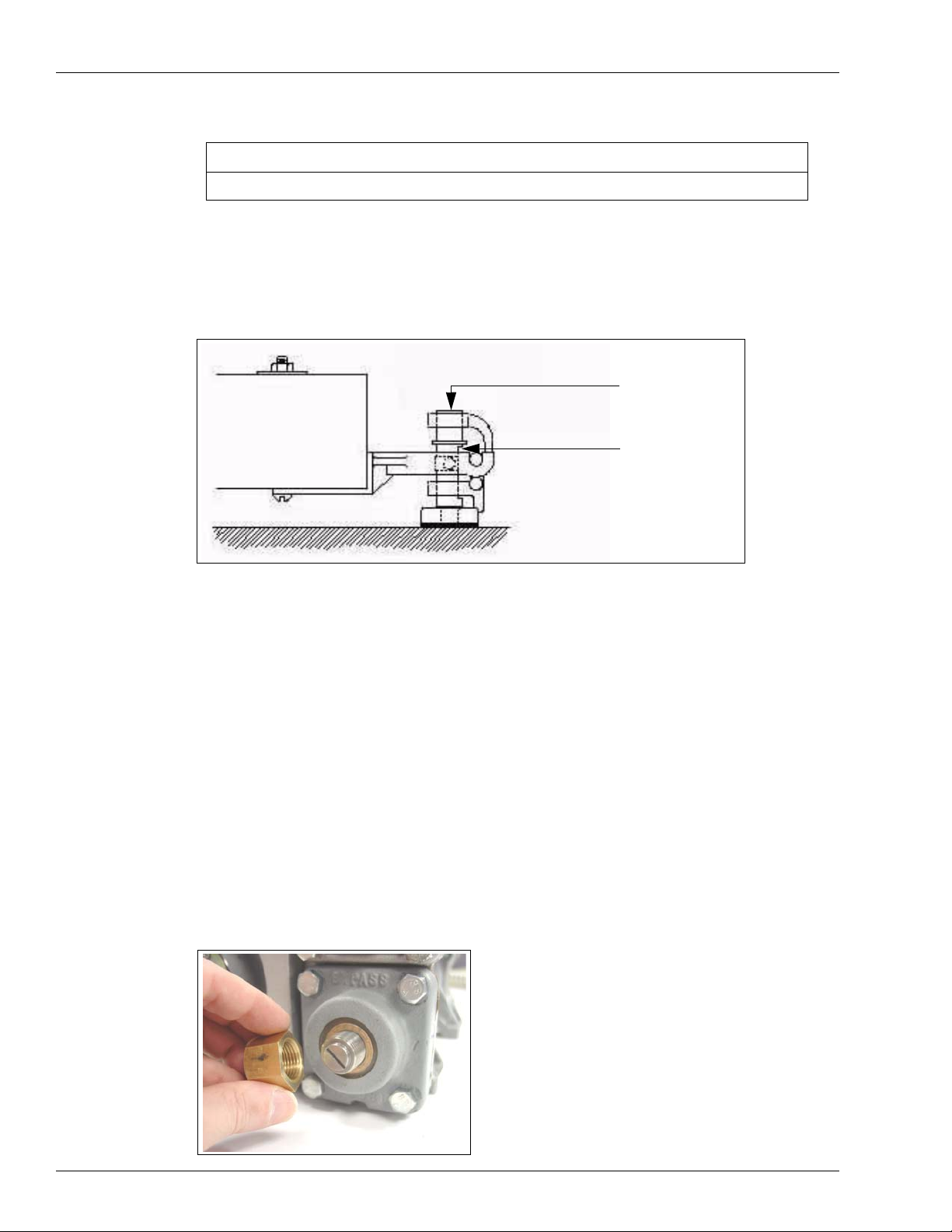
Air Separator Float Device
On OIML Euro versions of the pumping unit, a float assembly is provided on the pumping unit
vent opening. This assembly is used to prevent liquid from escaping through the vent pipe. See
Figure 3-4.
Figure 3-4: Air Separator Float Device
Control Valve
The pumping unit uses a control valve that aids in the elimination of air by producing a back
pressure and is also used as a check valve for any fuel above it.
The control valve also contains a pressure relief valve. This valve relieves excess hose
pressure, which may result from the expansion of fuel in the hose during hot weather, to the air
eliminator chamber. This action prevents hoses from bursting and helps prevent pumping unit
leaks.
Figure 3-5: Control Valve
MDE-4447A Global Pumping Unit Operation and Service Manual · May 2008 Page 7

Pumping Unit Operation and Maintenance Lip Seal Replacement
Lip Seal Replacement
To replace the lip seal, proceed as follows:
1 Remove the belt, pulley, and shaft key.
2 Remove the three screws that hold the seal retainer. See Figure 3-6. Carefully pry the old seal
from the recess in the cover plate.
Note: Do not scratch the shaft.
3 Wipe the shaft clean.
4 With a small plastic plug tool (furnished with new seal), slip the new seal over the shaft.
Remove the tool.
5 Reinstall the seal retainer screws, key, pulley, and belt.
Figure 3-6: Lip Seal Replacement
Stator
Seal
Retainer
Remove Plastic Plug
After Assembling Lip
Seal to Rotor Shaft
Lip
Seal
Screw
Inner
Seal
A 52 5702
Page 8 MDE-4447A Global Pumping Unit Operation and Service Manual · May 2008
Pumping Units with Throw-Out Rings Pumping Unit Operation and Maintenance
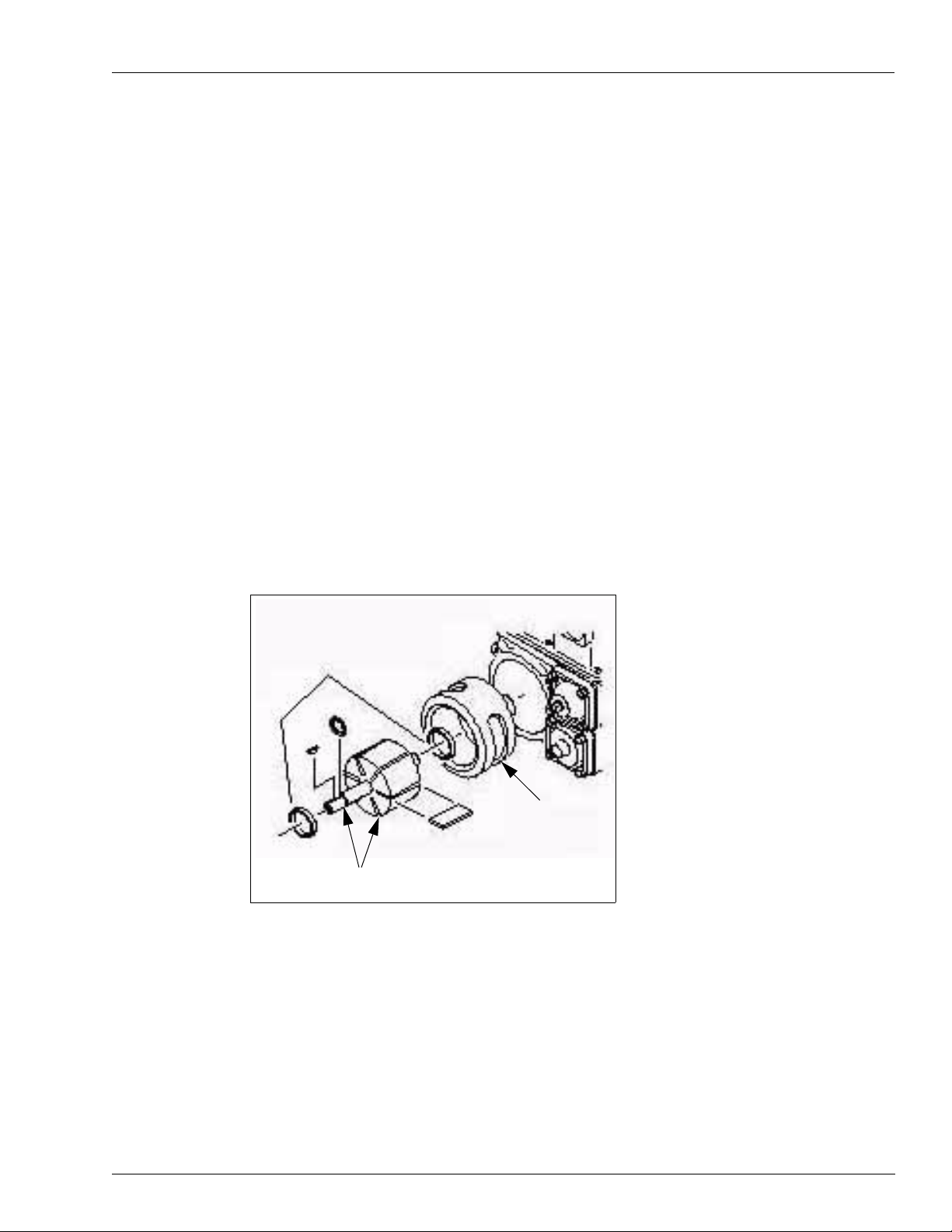
Pumping Units with Throw-Out Rings
All pumping units have rotors with throw-out rings and carbon blades.
Note: Studies conclude that pumping units with throw-out rings produce greater vacuum and
are more resistant to vapor lock.
To replace blades in rotors with throw-out rings, proceed as follows:
1 Install throw-out rings in the recesses of the rotor.
2 Install the rotor in the stator assembly.
3 Rotate the rotor until a blade slot is at the 12:00 o'clock position. Install a blade.
4 Rotate the rotor two slots from the installed blade. Ensure that the second slot is at the 12:00
o'clock position. Install a blade.
5 Repeat step 4 for the third blade.
6 Repeat steps 1 to 3 for the three remaining blades. See Figure 3-7.
Figure 3-7: Pumping Units with Throw-Out Rings
Blade Slot at 12:00 o’clock Position
Throw-out Rings
Stator
Rotor and Shaft
Assembly
MDE-4447A Global Pumping Unit Operation and Service Manual · May 2008 Page 9

Pumping Unit Operation and Maintenance Pumping Units with Throw-Out Rings
This page is intentionally left blank.
Page 10 MDE-4447A Global Pumping Unit Operation and Service Manual · May 2008

Parts Lists and Kits Model M04920B003
4 – Parts Lists and Kits
Model M04920B003
Figure 4-1: Pumping Unit - United States
MDE-4447A Global Pumping Unit Operation and Service Manual · May 2008 Page 11

Model M04920B003 - Pumping Unit Parts List Parts Lists and Kits
Model M04920B003 - Pumping Unit Parts List
Notes:1) Parts listed in the following table are not available for individual purchase. Repair
kits may be purchased. Refer to “Kits for M04920B003 and M04920B015” on
page 19.
2) Refer to “Adjustable Bypass Parts Breakdown” on page 13 and “Plug and Fitting
Parts Breakdown” on page 14 for additional parts and graphics.
Item Part Description Quantity Item Part Description Quantity
1 Body (non-reverse
float)
Body (reverse float) 1 32 Seal, Retainer 1
2 Blade, Rotor 10, see Note 2 33 Seal, Square 1
3 Clamp (see Note 1) 1 34 Rotor and Shaft Assembly 1, see Note 2
4 Connector, Male 1 19 • Key 1
5 Cover, Atmos.
Chamber
6 Cover, Bypass Valve 1 36 Screw (see Note 1) 1
7 Cover, Control Valve 1 37 Screw, M8 1.25x15mm 1
8 Cover, Filter 1 38 Screw, M8 1.25x20mm
9 Float, Non-Reversing 1 39 Screw, M8 1.25x25mm 24
11 Gasket, Atmos. Cham.
Cover
12 Gasket, Bypass Valve 1 41 Separator & Air Eliminator 1
13 Gasket, Clamping
Ring
14 Gasket, Control Valve
Cover
15 Gasket, Filter Cover 1 44 Spring, Filter 1
16 Gasket, Inlet
(separator)
17 Gasket, Outlet
(separator)
18 Inse rt 1 47 Strainer Assembly-149
19 Key 1 • Strainer, 70 Micron 1
20 Nut, Tube (see Note 1) 1 • Paper Filter (not
21 Nut 1 48 Tube, Vent Assy- 9024
22 O-ring 1 Tube, Vent Assy- 9033
23 Plug, Pipe 1/4” 2 Tube, Vent Assy- 9044
24 Pulley 1 49 Valve Assembly, Bypass 1
25 Ring, Throw Out
(H.D.)
1 31 Seal, Lip (with plug) 1
1 35 • Ring, Retaining 1
(see Note 1)
1 40 Screw, M6 1x20mm 6
1 42 Sleeve, Tube (see Note 1) 1
1 43 Spring, Control Valve
(H.D.)
1 45 Stator, H.D. 1
1 46 Stop, Filter Insert 1
micron
shown)
(see Note 1)
and 9036
and 9048
2 50 Valve Assembly, Control 1
-
1
1
1
2
3
4
Page 12 MDE-4447A Global Pumping Unit Operation and Service Manual · May 2008

Parts Lists and Kits Model M04920B003 - Pumping Unit Parts List
Item Part Description Quantity Item Part Description Quantity
26 Ring, Clamping 1 51 Valve, Relief 30-50 PSI 1
27 Ring, Retaining 1 52 Valve Assembly, Float 1
28 Rotor Support
Assembly
29 Cover, Rotor 1 54 Washer (see Note 1) 2
30 Screw, M3.5 Flat Hd 3 55 Washer, Lock 1
Notes:
1. Not part of the pumping unit.
2. Current pumping units use a 10-blade assembly. If you have a 6 or 8-blade rotor assembly, you can replace
blades, but the replacement rotor assembly uses a 10-blade design. When you need to replace the blades, it
is also recommended that you replace 6 or 8-blade rotor assemblies with a 10-blade rotor assembly for
quieter operation and better performance.
1 53 Washer 1
Adjustable Bypass Parts Breakdown
Refer to the table below Figure 4-3 on page 14 for a parts listing.
Figure 4-2: Adjustable Bypass Parts Breakdown
58
60
61
59
MDE-4447A Global Pumping Unit Operation and Service Manual · May 2008 Page 13

Model M04920B003 - Pumping Unit Parts List Parts Lists and Kits
Plug and Fitting Parts Breakdown
Refer to the table below Figure 4-3 on page 14 for a parts listing.
Figure 4-3: Plug and Fitting Parts Breakdown
56
57
Item Part Description
56 Fitting
57 Pipe Plug
58 Nut
59 Screw - Adjustable
60 Cover
61 Gasket - screw
Page 14 MDE-4447A Global Pumping Unit Operation and Service Manual · May 2008

Parts Lists and Kits Model M04920B015
Model M04920B015
Figure 4-4: Pumping Unit (Euro and Heavy Duty OIML Euro)
MDE-4447A Global Pumping Unit Operation and Service Manual · May 2008 Page 15

Model M04920B015 - Pumping Unit Parts List Parts Lists and Kits
Model M04920B015 - Pumping Unit Parts List
Notes:1) Parts listed in the following table are not available for individual purchase. Repair
kits may be purchased. Refer to “Kits for M04920B003 and M04920B015” on
page 19.
2) Refer to “Adjustable Bypass Parts Breakdown” on page 17, “Air Eliminator Float
Assembly Parts Breakdown” on page 18 and “Air Eliminator Float Assembly Parts
Breakdown” on page 18 for additional parts and graphics.
Item Part Description Quantity Item Part Description Quantity
1 Body (non-reverse
float)
Body (reverse float) 1 32 Seal, Retainer 1
2 Blade, Rotor 10, See Note 2 33 Seal, Square 1
3 Clamp (see Note 1) 1 34 Rotor and Shaft Assembly 1, See Note 2
4 Connector, Male 1 19 • Key 1
5Cover, Atmos.
Chamber
6 Cover, Bypass Valve 1 36 Screw (see Note 1) 1
7 Cover, Control Valve 1 37 Screw, M8 1.25x15mm 1
8 Cover, Filter 1 38 Screw, M8 1.25x20mm
9 Float, Non-Reversing 1 39 Screw, M8 1.25x25mm 24
11 Gasket, Atmos. Cham.
Cover
12 Gasket, Bypass Valve 1 41 Separator & Air Eliminator 1
13 Gasket, Clamping Ring 1 42 Sleeve, Tube (see Note 1) 1
14 Gasket, Control Valve
Cover
15 Gasket, Filter Cover 1 44 Spring, Filter 1
16 Gasket, Inlet
(separator)
17 Gasket, Outlet
(separator)
1 31 Seal, Lip (with plug) 1
1 35 • Ring, Retaining 1
(see Note 1)
1 40 Screw, M6 1x20mm 6
1 43 Spring, Control Valve
(H.D.)
1 45 Stator, H.D. 1
1 46 Check Valve 1
-
1
18 Insert 1 46A O-ring 1
19 Key 1 47 Strainer Assembly-149
micron
20 Nut, Tube (see Note 1) 1 • Strainer, 70 Micron 1
21 Nut 1 • Metal Strainer (not
shown)
22 O-ring 1 48 Tube, Vent Assy- 9024
(see Note 1)
23 Plug, Pipe 1/4 2 Tube, Vent Assy- 9033 &
9036
24 Pulley 1 49 Valve Assembly, Bypass 1
25 Ring, Throw Out (H.D.) 2 50 Valve Assembly, Control 1
26 Ring, Clamping 1 51 Valve, Relief 30-50 PSI 1
1
1
2
3
Page 16 MDE-4447A Global Pumping Unit Operation and Service Manual · May 2008

Parts Lists and Kits Model M04920B015 - Pumping Unit Parts List
Item Part Description Quantity Item Part Description Quantity
27 Ring, Retaining 1 52 Valve Assembly, Float 1
28 Rotor Support
Assembly
29 Cover, Rotor 1 54 Washer (see Note 1) 2
30 Screw, M3.5 Flat Hd 3 55 Washer, Lock 1
Notes:
1. Not part of the pumping unit.
2. Current pumping units use a 10-blade assembly. If you have a 6 or 8-blade rotor assembly, you can replace
blades, but the replacement rotor assembly uses a 10-blade design. When you need to replace the blades, it is
also recommended that you replace 6 or 8-blade rotor assemblies with a 10-blade rotor assembly for quieter
operation and better performance.
1 53 Washer 1
Air Eliminator Parts Breakdown
Refer to the table below Figure 4-7 on page 18 for a parts listing.
Figure 4-5: Air Eliminator Parts Breakdown
60
61
62
Adjustable Bypass Parts Breakdown
Refer to the table below Figure 4-7 on page 18 for a parts listing.
Figure 4-6: Adjustable Bypass Parts Breakdown
72
73
74
63
75
MDE-4447A Global Pumping Unit Operation and Service Manual · May 2008 Page 17

Model M04920B015 - Pumping Unit Parts List Parts Lists and Kits
Air Eliminator Float Assembly Parts Breakdown
Refer to the table below Figure 4-7 for a parts listing.
Figure 4-7: Air Eliminator Float Assembly Parts Breakdown
65
64
Item Part Description
56 Clip (not shown)
57 End Plug (not shown)
58 O-ring (not shown)
59 Separator (not shown)
60 Air Separator Tube Variable Orifice
61 Piston Air Separator Tube Variable Orifice
62 Spring
63 End Cap Separator Tube Variable Orifice
64 3/8-inch Pipe Plug
65 Housing Air Valve Float Assembly
66 Gasket Air Valve Float Assembly
67 Needle Air Valve Float Assembly
68 Gland Nut Air Valve Float Assembly
69 Float - Air Valve Float Assembly
70 Retaining Ring - External 3.5mm
71 Retaining Ring - External 3.5mm
72 Nut
73 Screw - Adjustable
74 Gasket - Screw
75 Cover
69
71
67
68
70
Page 18 MDE-4447A Global Pumping Unit Operation and Service Manual · May 2008

Parts Lists and Kits Kits for M04920B003 and M04920B015
Kits for M04920B003 and M04920B015
The kits listed in the table below are available for Gilbarco Global Pumping Units. Refer to
“Kit Component Parts” on page 20 for additional information.
Kit Number Kit Description
M04920K100 Bypass Valve
M04920K101 Strainer
M04920K102 Master Seal
M04920K104 Control Valve
M04920K105 Lip Seal
M04920K107 Sump Float - OIML (B005)
M04920K109 Inlet Check Valve
M04920K110 Overflow Che ck Valve
M04920K116 Blades
M04920K117 Pumping Element Field Rebuild
M04920K118 Pumping Element Shop Rebuild
M04920K119 Inlet Adapter
Note: Alternate Fuel Pumps M04920B011 and M04920B0 12 require special kits.
Contact Gilbarco's Engineering Department for assistance.
Kit Revision History
Kit Number Kit Description
M04920K103 Blades M04920K113
M04920K106 Pumping Elemen t Field Rebuild M04920K114
M04920K108 Pumping Element Shop Rebuild M04920K115
M04920K111 Sump Float - Non OIML (B001) M04920K107
M04920K112 Blades M04920K113
M04920K113 Blades M04920K116
M04920K114 Pumping Element Field Rebuild M04920K117
M04920K115 Pumping Element Shop Rebuild M04920K118
Replacement Kit
Number
MDE-4447A Global Pumping Unit Operation and Service Manual · May 2008 Page 19

Kit Component Parts Parts Lists and Kits
Kit Component Parts
M04920K100 - Bypass Valve M04920K117 - Pumping Element Field Rebuild
Bypass Valve • 10-blade Rotor and Shaft
M04920K101 - Strainer
70 Micron Strainer • Retaining Ring
M04920K102 - Master Seal
• Clamp Ring Gasket • Shaft Seal w/ Plug
• Bypass Valve Cover Gasket • Square Seal
• Control Valve Cover Gasket
• Filter Cover Gasket • 10-blade Rotor and Shaft
• Atmos. Chamb. Cover Gasket • Blade
• Inlet Gasket • Throw out Ring
M04920K104 -Control Valve
• Control Valve • Rotor Cover
• Heavy Duty Spring • Rotor Cover Gasket
M04920K105 - Lip Seal
• Lip Seal • Shaft Seal w/ Plug
• Square Seal • Square Seal
•Blade
• Woodruff Key
M04920K118 - Pumping Element Shop Rebuild
• Retaining Ring
• Woodruff Key
M04920K107 - Sump Float - OIML (B005) M04920K119 - Inlet Adapter
• Float Valve Assembly (Rogers) • Inlet Adapter
•O-Ring •Gasket
• Non-Reversing Float • Bolt
M04920K109 - Inlet Check Valve
•O-Ring
• Check Valve Assembly
M04920K110 - Overflow Check Valve
• Air Valve Housing
• Air Valve Gasket
• Valve Sub Assm. Air Vent
• Float (Rogers)
• Retaining Ring
M04920K116 - Blades
•Blade
• Shaft Seal w/ Plug
• Square Seal
Page 20 MDE-4447A Global Pumping Unit Operation and Service Manual · May 2008

General Vacuum and Pressure Information Troubleshooting
5 – Troubleshooting
General Vacuum and Pressure Information
The following components are normally associated with pump pressure:
• Control Valve
• Meter
• Computer or Pulser Drive Linkage
•Hose
• Nozzle
The following components are normally associated with pump vacuum:
•Blades
• Rotor/Stator
• Filter
• Bypass Valve and Seat
• Float (opened)
• Installation piping
• Tank Vent Pipe
• Angle Check Valve or Foot Valve
• Tank burial depth
Vacuum readings can vary with each installation. To calculate pump vacuum, proceed as
follows:
1 An inch of mercury is required to lift gasoline 1-1/2 feet. Divide the total lift by 1-1/2 feet to
obtain vacuum.
2 Allow an inch of mercury for each angle check, foot valve, or vertical check valve.
3 Allow an inch of mercury for each 60 feet of piping.
4 Add the readings obtained in steps 1, 2 and 3 to determine the approximate vacuum reading at
fast flow.
Note: Excessive vacuum indicates a restriction. Low vacuum indicates a leak.
MDE-4447A Global Pumping Unit Operation and Service Manual · May 2008 Page 21

Troubleshooting Vacuum Gauge Readings (Inches of Mercu r y)
Vacuum Gauge Readings (Inches of Mercury)
The following table shows normal vacuum gauge readings for a variety of lift vs. run
situations.
Notes:1) The following table shows normal vacuum gauge readings for general lift vs. run
situations. This is intended as a guideline only. Readings will vary depending on
other factors, such as pipeline size, number of bends, elevation, fuel composition and
so on.
2) Readings are listed in inches of mercury (in-hg). Some gauges may read in
centimeters of mercury (cm-hg), Pounds per Square Inch (PSI) or bar. See
Conversion Factors.
Vertical Lift (Feet)345678910
Horizontal Run - 0 feet 3.0 3.6 4.3 4.9 5.5 6.1 6.8 7.4
Horizontal Run - 60 feet 3.9 4.5 5.2 5.8 6.4 7.0 7.7 8.3
Conversion Factors
• 1 in-hg = 2.54 cm-hg
• 1 in-hg = -0.491 PSI
• 1 in-hg = -0.034 bar
• 1 ft = 0.3048 meter
Use Gauge Readings to Troubleshoot Self-Contained Dispensers
There are a variety of conditions that can contribute to no delivery or slow delivery. A
pressure/vacuum gauge is an important tool in determining whether the problem is on the
vacuum side or pressure side of the pump.
The vacuum gauge reading can help you determine if there are restrictions of flow in the
suction piping system. It will also help you determine the ability of the pumping unit to pump.
Note: Vacuum gauge readings in the following sections are shown in inches of mercury.
Testing Pump Vacuum
To test the vacuum of the pump, proceed as follows:
1 Remove the pipe plug in the center of the strainer or filter cover. The cover is marked for easy
identification.
2 Install the vacuum gauge.
3 Start the pump and open the nozzle to full flow for a true reading.
Page 22 MDE-4447A Global Pumping Unit Operation and Service Manual · May 2008

Use Gauge Readings to Troubleshoot Self-Contained Dispensers Troubleshooting
4 With the nozzle open, a normal vacuum reading is 6-8 inches of mercury for normal suction.
See Figure 5-1.
Figure 5-1: Vacuum Reading - Nozzle Open
With the nozzle closed, a normal vacuum reading is 0. See Figure 5-2.
5
Figure 5-2: Vacuum Reading - Nozzle Closed
Testing Pump Pressure
To test the pressure of the pump, proceed as follows:
1 Remove the pipe plug in the center of the control valve cover. Covers are marked for easy
identification.
2 Install the pressure gauge.
3 Start the pump and open the nozzle to full flow for a true reading.
4 With the nozzle open, a normal pressure reading is 16-18 PSI pressure.
5 With the nozzle closed, a normal pressure reading is 25-28 PSI pressure. See Figure 5-3 on
page 24.
MDE-4447A Global Pumping Unit Operation and Service Manual · May 2008 Page 23

Troubleshooting Troubleshooting Using Gauge Readings
Figure 5-3: Pressure Reading - Nozzle Closed
Troubleshooting Using Gauge Readings
The following examples help you determine the possible cause of a problem by observing the
gauge readings on the inlet (vacuum) and outlet (pressure) side of the pumping unit. Actual
readings may vary slightly, depending on installation and environmental conditions.
Figure 5-4: Gauge Troubleshooting 1
Symptoms: No Flow; Nozzle Open
Check Inlet Side
Probable Causes:
• Control Valve Stuck Shut
• Bypass Valve Open
• Atmospheric Float Valve Open
At Control Valve
Cover
• Stuck Rotor Blades
• Broken Suction Line
• Strainer or Filter Completely
Plugged or in Backwards
• Empty Tank
At Strainer
(or Filter)
Cover
Page 24 MDE-4447A Global Pumping Unit Operation and Service Manual · May 2008

Troubleshooting Using Gauge Readings Troubleshooting
Figure 5-5: Gauge Troubleshooting 2
Symptoms: No Flow; Nozzle Open
Probable Causes:
• Seized Meter
• Jammed Computer or Geared
Box
• Completely Restricted Nozzle or
Hose
At Control Valve
Cover
Symptoms: Slow or No Flow; Pump
Laboring; Nozzle Open
Check Inlet Side
At Strainer (or Filter)
Cover
At Control Valve
Cover
At Control Valve
Cover
Probable Causes:
• Supply Line Restriction
• Stuck Foot Valve (in Tank)
• Angle Check Valve or Vertical
Check Valve
• Restricted Tank Vent
Symptoms: Slow or No Flow;
Nozzle Open
Check Outlet Side
Probable Causes:
• Control Valve not Opening Fully
• Pump Vapor Locked
At Strainer (or Filter)
Cover
At Strainer (or Filter)
Cover
MDE-4447A Global Pumping Unit Operation and Service Manual · May 2008 Page 25

Troubleshooting Troubleshooting Using Gauge Readings
Figure 5-6: Gauge Troubleshooting 3
Symptoms: No Flow or Slow
Delivery; Nozzle Open
Probable Causes:
• Worn Bypass Valve or Rotor
Blades
• Worn Rotor or Stator
• Air Leak in Suction Pipe
At Control Valve
Cover
• Dirty Filter
Symptoms: Slow Flow; Nozzle
Open
Check Outlet Side
At Strainer (or Filter)
Cover
At Control Valve
Cover
At Control Valve
Cover
Probable Causes:
• Partially Restricted Nozzle or
Hose
• Bind in Computer, Gear Box,
Meter
• Pulser Drive Linkage
Symptoms: No Flow or Slow
Delivery; Nozzle Open
Probable Cause:
• Tank Burial Too Deep (High Lift)
At Strainer (or Filter)
Cover
At Strainer (or Filter)
Cover
Page 26 MDE-4447A Global Pumping Unit Operation and Service Manual · May 2008

Resolving Problems on Pumping Units Troubleshooting
Figure 5-7: Gauge Troubleshooting 4
Symptoms: Motor Laboring;
Circuit Breaker Trips; Motor
Failing; Nozzle Closed
Probable Cause:
• Bypass Valve Stuck Shut
Reading
At Control Valve
May Vary
Cover
At Strainer (or Fil ter)
Cover
Resolving Problems on Pumping Units
Refer to the following tables for specific troubleshooting information.
Problem
The motor starts but the pump does not deliver fuel.
Cause Action
The fuel supply is below the suction stub in
the storage tank.
The vent pipe is plugged in the storage tank. Clean the vent pipe.
The strainer screen or filter assembly has an
obstruction.
The bypass valve is not seated properly due
to wear or obstruction.
The v-belt is loose or broken. Adjust or replace the v-belt.
There is an obstruction in the atmospheric
float valve.
The pump is out of prime. Check for a faulty foot valve in the storage tank or a faulty check
The suction line is leaking. Start the pump and open the nozzle. If bursts of air are felt while
The intake line, foot valve, angle check
valve, or vertical check valve have an
obstruction.
The suction stub in the storage tank is on the
bottom of the tank.
The control valve has an obstruction. Clean the control valve. It must slide freely in the valve cavity.
The nozzle is not working. Replace the nozzle.
Two pumps are connected to one storage
tank with one suction line. There is a faulty
check valve in one of the supply lines*.
Fill the storage tank.
Remove obstructions from the screen or filter assembly.
Check the valve for an obstruction causing the valve to stay
open, and/or replace the bypass valve.
Clean the float and valve area. Check for swelling and binding
in the linkage.
valve in the suction line.
holding a finger on the vent tube, the suction line is damaged.
Repair or replace.
Connect a vacuum gauge to the 1/4 inch plug on the filter cover.
Turn the pump on and open the nozzle. A reading of 15 or more
inches of mercury with no flow indicates a complete blockage in
the suction line. Clean the line or replace.
Ensure that there is a four-inch clearance.
Disconnect the vent tube on the idle pump. Install a short
copper tube. Place the end of the copper tube in a container of
liquid. If the liquid is drawn out of the container when the
opposite pump is operated with an open nozzle, the line check
valve is faulty. Replace the check valve.
MDE-4447A Global Pumping Unit Operation and Service Manual · May 2008 Page 27

Troubleshooting Resolving Problems on Pump ing Units
Cause Action
*Not recommended.
Problem
The pump runs, but delivery is slow.
Cause Action
The fuel supply level is low. Fill the storage tank.
The vent pipe is partially obstructed. Clean the vent pipe.
The strainer screen or filter assembly has a
partial obstruction.
The bypass valve is not seated properly. Check the valve for any obstructions which may cause the valve to
The v-belt is loose. Adjust the v-belt.
The voltage is too low. Check the power supply voltage. The dispenser uses a 115 VAC,
A blade or blades in the rotary pump will not
move.
An automatic nozzle has been installed. Delivery speed will be reduced by 10-25%. If the maximum speed
The motor is defective. Inspect the motor for loose connections. If no loose connections
There is a slow leak in the suction line or
intake line.
The intake line, foot valve, angle or vertical
check valve is partially obstructed.
The control valve is partially obstructed. Check the valve for an obstruction. Replace if necessary.
The nozzle check valve is sticky. Clean or replace the nozzle check valve.
The hose is defective (flattened). Replace the hose.
Remove obstructions from the screen or filter assembly.
stay open.
60 cycle electrical circuit. Check for many pieces of equipment on
one electrical line.
Check the rotor and blades for damage. Replace the blades and/
or rotor, if necessary.
is desired, replace with a standard nozzle.
are found, the motor is defective. Repair or replace.
Start the pump and open the nozzle. If bursts of air are felt while
holding a finger on the vent tube, the suction line or intake line is
damaged. Repair or replace.
Connect a vacuum gauge to the 1/4 inch plug on the filter cover.
Turn the pump on and open the nozzle. A reading of 11 to 13
inches of mercury with no flow indicates a partial obstruction in the
suction line. Clean or replace the suction line components.
Problem
The motor will not run.
Cause Action
The power is off. Check the circuit breaker in the station.
The motor is defective. Disconnect the power supply. Inspect the motor for loose
connections. If no loose connections are found, the motor is
defective. Repair or replace.
Problem
The dispenser does not deliver an accurate amount of product.
Cause Action
There is an obstruction in the control
valve.
There is an obstruction in the air
eliminator vent tube.
Page 28 MDE-4447A Global Pumping Unit Operation and Service Manual · May 2008
Clean the control valve. It must slide freely in the valve cavity.
Clean the vent tube.

Resolving Problems on Pumping Units Troubleshooting
Cause Action
The meter needs calibration. Check calibration test equipment for accuracy. Calibrate the meter.
Problem
There is fuel running out of the vent tube opening when the pump is in operation.
Cause Action
There is an obstruction in the atmospheric
float valve. The valve is being held closed.
The suction chamber in the pump is
flooded (above ground tank)*.
* Not recommended.
Clean the float and valve area. Ensure that the float opens completely.
Check the storage tank level. If it is higher than the pumping unit
(above ground tank)*, the condition will continue. Install Tokheim 52
valve.
Problem
The computer jumps when the pump is turned on.
Cause Action
The control valve is not seated properly. Check the valve for an obstruction between the O-Ring and the seat.
Inspect the O-Ring for damage. Replace the valve or O-Ring, if
required.
There is an obstruction in the expansion
relief dill valve.
The gaskets are leaking. Replace worn gaskets.
There is a worn nozzle. Replace the nozzle.
There is a leak in the hose. Replace the hose.
Temperature extremes cause the liquid to
expand or contract.
Check the valve by pulling the spring loaded seat. Clean any foreign
matter from the valve. To install the dill valve in the control valve, use
a valve tool.
Problem will be solved when the pump begins to operate.
MDE-4447A Global Pumping Unit Operation and Service Manual · May 2008 Page 29

Troubleshooting Resolving Problems on Pump ing Units
This page is intentionally left blank.
Page 30 MDE-4447A Global Pumping Unit Operation and Service Manual · May 2008

Vapor Lock Causes Reasons for Vapor Lock
6 – Vapor Lock Causes
Vapor Lock is a problem that results from ambient temperatures, vapor pressure of the product
and installation. It is not a characteristic of a pump.
Reasons for Vapor Lock
Atmospheric Pressure
Atmospheric Pressure of 14.7 PSI (sea level) presses on the liquid in the tank. See Figure 6-1.
Figure 6-1: Atmospheric Pressure
Atmospheric
Pressure (14.7 PSI)
60º F
MDE-4447A Global Pumping Unit Operation and Service Manual · May 2008 Page 31

Reasons for Vapor Lock Vapor Lock Causes
Vapor Pressure
Vapor Pressure (the amount of pressure required to keep the product in a liquid form at 60° F)
of today's product is approximately 10 PSI. See Figure 6-2 on page 32.
Figure 6-2: Vapor Pressure
10 PSI required to keep
product in liquid form
60º F
Working Pressure
The difference between Atmospheric Pressure and Vapor Pressure is known as the Working
Pressure. The Working Pressure is all that the pump can c reate without the product turning to
vapor. See Figure 6-3.
14.7 PSI Atmospheric Pressure
- 10.0 PSI Vapor Pressure
4.7 PSI Working Pressure
Figure 6-3: Working Pressure
Atmospheric
Pressure
Less
Vapor Pressure
equals
Working Pressure
60º F
14.7 PSI
10.0 PSI
4.7 PSI
Page 32 MDE-4447A Global Pumping Unit Operation and Service Manual · May 2008

Vapor Lock Causes Reasons for Vapor Lock
Measuring Suction
To measure a pump’s suction, the Working Pressure must be converted to inches of vacuum.
To do this, multiply the Working Pressure by 2. The result is the number of inches of vacuum
that a pump can create before the product changes to a vapor. See Figure 6-4.
Figure 6-4: Converting Working Pressure to Inches of Vacuum
Atmospheric
Pressure (14.7 PSI)
equals 30 inches of
mercury
14.7 PSI of Atmospheric
Pressure pushes down
on the bowl of mercury
and causes it to rise to 30
inches.
4.7 PSI Working Pressure = 9.4 inches of vacuum. See Figure 6-5.
Figure 6-5: PSI and Vacuum Equivalents
4.7 PSI = 9.4 inches of Vacuum
PSI
Vacuum
MDE-4447A Global Pumping Unit Operation and Service Manual · May 2008 Page 33

Reasons for Vapor Lock Vapor Lock Causes
Installation is the Key
The condition of installation dictates how much suction a pump must create to pump the
product.
It takes 1 inch of vacuum to lift gas 1.5 feet vertically.
To determine the inches of vacuum required to lift the gas in a system, proceed as follows:
1 Measure the distance from the top of the product in the tank to the center of the pumping unit.
See Figure 6-6. Divide the distance by 1.5 to obtain the inches of vacuum required by the
pump to lift the product.
For example: 9 feet of lift requires 6 inches of vacuum by the pump. See Figure 6-6.
Figure 6-6: Amount of Vacuum Required for Pump Suction
Amount of
Lift
Vacuum
Required
60º F
It takes 1 inch of vacuum by the pump to overcome the restriction of an angle check valve or
foot valve (not part of the pump, but a necessary part of the installation). See Figure 6-7.
Figure 6-7: Compensating for Angle Check or Foot Valve
1 inch of vacuum to overcome the restriction
of an angle check valve or foot valve
Angle Check Valve
Foot Valve
Page 34 MDE-4447A Global Pumping Unit Operation and Service Manual · May 2008

Vapor Lock Causes Reasons for Vapor Lock
It takes 1 inch of vacuum by the pump to overcome the restriction of 60 feet of horizontal
piping from the tank to the pump. See Figure 6-8.
Figure 6-8: Compensating for Horizontal Piping
60 Feet of Horizontal Piping = 1 inch of Vacuum
60ºF
To obtain the inches of vacuum required to deliver the product, simply add A, B and C.
2
A. 9 feet of lift = 6 inches of suction
B. Angle check or foot valve= 1 inch of suction
C. 60 feet horizontal run= 1 inch of suction
TOTAL 8 inches of suction
With 9.4 inches of suction to work with and only 8 inches of vacuum required, conditions are
normal and the pump delivers the product without vapor locking.
Note: This condition exists when the product is at 60° F.
MDE-4447A Global Pumping Unit Operation and Service Manual · May 2008 Page 35

Vapor Lock Conditions Vapor Lock Causes
Vapor Lock Conditions
Using the same example as above, 8 inches of vacuum is still required to deliver the product.
With higher ambient temperatures, the vapor pressure of the product changes. As mentioned
above, the Vapor Pressure of today's product is 10 PSI at 60° F. At temperatures of 90° F or
higher, it can go as high as 12 PSI.
Figure 6-9: Vapor Pressure at 95º F
95º F
Vapor Pressure of Product
may be as high as 12 PSI
Using the same formulae in “Working Pressure” on page 32, the Working Pressure equals
Atmospheric Pressure less the Vapor Pressure. See Figure 6-10.
14.7 PSI Atmospheric Pressure
- 12.0 PSI Vapor Pressure of the product
2.7 PSI Working Pressure
Figure 6-10: Working Pressure - Vapor Lock Conditions
Atmospheric
Pressure
Less
95º F
14.7 PSI
Vapor Pressure
equals
Working Pressure
Page 36 MDE-4447A Global Pumping Unit Operation and Service Manual · May 2008
12.0 PSI
2.7 PSI

Vapor Lock Causes Vapor Lock Conditions
Multiplying the 2.7 Working Pressure by 2 equals 5.4 inches of vacuum that the pump can
create before the product turns to vapor. See Figure 6-11 on page 37.
Figure 6-11: PSI and Vacuum Equivalents - Vapor Lock Conditions
2.7 PSI = 5.4 inches of Vacuum
PSI
Vacuum
It still takes 8 inches of vacuum to deliver the product, but with higher temperatures, there is
only 5.4 inches of vacuum to lift the product. The result is Vapor Lock.
Figure 6-12: Vapor Lock Conditions
The pump plays a very small part in vapo r lock situations. The main reasons for vapor lock are
as follows:
• Installation
• Amount of product in the storage tank
• Vapor Pressure of the product
Note: Vapor lock does not occur in diesel pumps because the Vapor Pressure of diesel is
approximately 8 PSI.
The only solution for vapor lock in hot climates is to keep the installation and pump cool.
MDE-4447A Global Pumping Unit Operation and Service Manual · May 2008 Page 37

Vapor Lock Conditions Vapor Lock Causes
© 2008 Gilbarco Inc.
7300 West Friendly Avenue · Post Office Box 22087
Greensboro, North Carolina 27420
Phone (336) 547-5000 · http://www.gilbarco.com · Printed in the U.S.A.
MDE-4447A Global Pumping Unit Operation and Service Manual · May 2008
 Loading...