

Page 1
This document is based on Orpak’s Truck Controller Unit (OrTC)
installation manual P/N 817438028
MDE-4814C
Fuel Truck Controller
INSTALLATION MANUAL
Page 2

Page 3

SAFETY CONSIDERATIONS
Read all warning notes and instructions carefully. They are included to help you installing the Product safely
in the highly flammable environment of the fuel station. Disregarding these warning notes and instructions
could result in serious injury or property damage. It is the installer responsibility to install, operate and
maintain the equipment according to the instructions given in this manual, and to conform to all applicable
codes, regulations and safety measures. Failure to do so could void all warranties associated with this
equipment.
Remember that the fuel station environment is highly flammable and combustible. Therefore, make sure
that actual installation is performed by experienced personnel, licensed to perform work in fuel station and at
a flammable environment, according to the local regulations and relevant standards.
For UL listing; All peripherals equipment connected to the device must be UL listed and suitable for the
applications.
WARNING - EXPLOSION HAZARD
Install the Product only in the non-hazardous area of the fuel station.
Use standard test equipment only in the non- hazardous area of the fuel station, and approved test equipment
for the hazardous areas.
In the installation and maintenance of the Product, comply with all applicable requirements of the National
Fire Protection Association NFPA-30 “Flammable and Combustible Liquids Code”, NFPA-30A “Code for
Motor Fuel Dispensing Facilities and Repair Garages”, NFPA-70 “National Electric Code”, federal, state and
local codes and any other applicable safety codes and regulations.
Do not perform metal work in a hazardous area. Sparks generated by drilling, tapping and other metal work
operations could ignite fuel vapors and flammable liquids, resulting in death, serious personal injury,
property loss and damage to you and other persons.
CAUTION - SHOCK HAZARD
Dangerous AC voltages that could cause death or serious personal injury are used to power the Product.
Always disconnect power before starting any work. The Product has more than one power supply connection
port. Disconnect all power before servicing.
CAUTION – EXTERNAL WIRING
For supply connections, use wires suitable for at least 90°C.
Signal wiring connected in this box must be rated at least 300 V.
Page 4

WARNING – PASSING VEHICLES
When working in any open area of fuel station, beware of passing vehicles that could hit you. Block off the
work area to protect yourself and other persons. Use safety cones or other signaling devices.
WARNING
Components substitutions could impair intrinsic safety.
Attaching unauthorized components or equipment will void your warranties.
CAUTION
Do not attempt to make any repair on the printed circuit boards residing in the Product, as this will void all
warranties related to this equipment.
PROPRIETY NOTICE
This document contains propriety and confidential information. It is the property of ORPAK SYSTEMS
Ltd. It may not be disclosed or reproduced in whole or in part without written consent of ORPAK
SYSTEMS. The information in this document is current as of the date of its publication, but is subject to
change without notice.
DISCLAIMER
This document is provided for reference only. Although every effort has been made to ensure correctness,
ORPAK SYSTEMS does not guarantee that there are no errors or omissions in this document.
FCC Compliance Statement
The FCC Wants You to Know:
This equipment has been tested and found to comply with the limits for a Class B digital device, pursuant to
Part 15 of the FCC rules. These limits are designed to provide reasonable protection against harmful
interference in a residential installation. This equipment generates uses and can radiate radio frequency
energy and, if not installed and used in accordance with the instructions, may cause harmful interference to
radio communications. However, there is no guarantee that interference will not occur in a particular
installation. If this equipment does cause harmful interference to radio or television reception, which can be
determined by turning the equipment off and on, the user is encouraged to try to correct the interference by
one or more of the following measures :
a) Reorient or relocate the receiving antenna.
b) Increase the separation between the equipment and receiver.
c) Connect the equipment to an outlet on a circuit different from that to which the receiver is connected.
d) Consult the dealer or an experienced radio/TV technician.
Page 5

FCC Warning
Modifications not expressly approved by the manufacturer could void the user authority to operate the
equipment under FCC Rules.
This document is the property of:
ORPAK SYSTEMS Ltd.
ISRAEL
Page 6

Page 7

i
TABLE OF CONTENTS
Paragraph
Page
SECTION 1 GENERAL DESCRIPTION
1-1. SCOPE ................................................................................................................................ 8
1-2. DESCRIPTION .................................................................................................................. 8
1-3. SYSTEM OVERVIEW ...................................................................................................... 9
1-3.1. Fuel Truck Controller System ........................................................................................ 9
1-3.2. Vehicle Identification ..................................................................................................... 9
1-3.3. Remote Web Access ...................................................................................................... 9
1-3.4. Fleet Head Office ........................................................................................................... 9
1-3.5. Restrictions and Limits .................................................................................................. 9
1-3.6. Fuel Truck Controller Capabilities for Mobile Station Management ............................ 10
1-3.7. System Workflow - Example ......................................................................................... 11
1-4. FUEL TRUCK CONTROLLER STRUCTURE ................................................................ 12
1-4.1. Main Components .......................................................................................................... 12
1-4.2. Fuel Truck Controller General Configuration ............................................................... 14
1-4.3. Fuel Truck Controller Main Components Location ....................................................... 15
1-5. AVAILABLE CONFIGURATIONS ................................................................................. 16
1-5.1. General ........................................................................................................................... 16
1-5.2. Vehicle Identification System – FuelPoint PLUS.......................................................... 16
1-5.3. WGT External Box – Optional ...................................................................................... 16
1-5.4. Safety Barriers ............................................................................................................... 17
1-5.5. Modem/Router ............................................................................................................... 18
1-5.6. External TAG Reader (OrTR)........................................................................................ 18
1-5.7. Fuel Truck Controller with OrTR and WGT ................................................................. 19
1-5.8. Fuel Truck Controller - Standard Models ...................................................................... 20
1-6. SECURITY AND PROTECTION ..................................................................................... 21
1-6.1. General ........................................................................................................................... 21
1-6.2. Authorization Security ................................................................................................... 21
1-6.3. Network Security ........................................................................................................... 21
1-6.4. RF Network Security ..................................................................................................... 21
1-6.5. Maintenance Security ..................................................................................................... 21
1-6.6. RTC Backup ................................................................................................................... 21
1-7. HOUSING .......................................................................................................................... 21
1-8. SPECIFICATIONS ............................................................................................................. 23
1-9. STANDARDS .................................................................................................................... 23
Fuel Truck Controller Manual
Page 8

ii
TABLE OF CONTENTS
Paragraph
Page
1-9.1. Communication Standards ............................................................................................. 23
1-9.2. Security Standards .......................................................................................................... 24
1-10. MANUAL STRUCTURE ................................................................................................... 25
1-11. USING THIS MANUAL .................................................................................................... 26
1-12. REFERENCES ................................................................................................................... 27
SECTION 2 PRELIMINARY INSTALLATION INSTRUCTIONS
2-1. GENERAL .......................................................................................................................... 28
2-2. PRELIMINARY INSTALLATION INSTRUCTIONS ..................................................... 28
2-2.1. General ........................................................................................................................... 28
2-2.2. Precautions and Safety Notes ......................................................................................... 29
2-3. CONDUITS INSTALLATION .......................................................................................... 29
2-3.1. General ........................................................................................................................... 29
2-3.2. Conduit Requirements .................................................................................................... 29
2-3.3. Type of Conduits in the Truck ....................................................................................... 30
2-3.4. Wiring Openings in Fuel Truck Controller .................................................................... 31
2-3.5. Conduits Installation Procedures .................................................................................... 31
2-4. CABLES ............................................................................................................................. 31
2-4.1. General ........................................................................................................................... 31
2-4.2. Cable Types .................................................................................................................... 32
2-4.3. Cables Routing ............................................................................................................... 32
2-5. Electrical System ................................................................................................................ 33
2-5.1. External Fuse .................................................................................................................. 33
2-5.2. Fuel Truck Controller Power System ............................................................................. 33
2-6. GROUNDING AND SHIELDING .................................................................................... 34
2-7. CONNECTIONS TO FUEL TRUCK CONTROLLER ..................................................... 35
SECTION 3 INSTALLATION PROCEDURES
3-1. GENERAL .......................................................................................................................... 37
3-2. INSTALLATION SPECIFICATIONS ............................................................................... 37
3-2.1. General ........................................................................................................................... 37
3-2.2. Precautions and Safety Notes ......................................................................................... 37
3-3. FUEL TRUCK - OVERVIEW ........................................................................................... 38
3-3.1. General ........................................................................................................................... 38
3-4. MAPPING THE TRUCK ................................................................................................... 39
Fuel Truck Controller Manual
Page 9

iii
TABLE OF CONTENTS
Paragraph
Page
3-4.1. General ........................................................................................................................... 39
3-4.2. Locating all objects of the fuel truck ............................................................................. 39
3-4.3. Assigning Logical IDs ................................................................................................... 39
3-5. INSTALLING THE FUEL TRUCK CONTROLLER ....................................................... 40
3-5.1. Installation Assembly Parts ............................................................................................ 40
3-5.2. Preliminary Procedures .................................................................................................. 41
3-5.3. Fuel Truck Controller Installation in Driver's Cabin ..................................................... 41
3-5.4. Determining the Spot Installation Fuel Truck Controller with Shock Absorber Assembly41
3-5.5. Shock Absorbers Assembly - Installation Procedures ................................................... 42
3-5.6. Fuel Truck Controller Installation Assembly ................................................................ 43
3-6. INSTALLATION OF FUEL TRUCK CONTROLLER WITH WALL MOUNT KIT ..... 44
3-6.1. Installation Assembly Parts ............................................................................................ 44
3-6.2. Installation Procedures ................................................................................................... 44
3-7. WIRING ............................................................................................................................. 46
3-7.1. General ........................................................................................................................... 46
3-7.2. Wiring Requirement ....................................................................................................... 46
3-7.3. Wiring Procedures ......................................................................................................... 46
3-7.4. General ........................................................................................................................... 46
3-7.5. Mechanical Pump – Terminal Block - Pin-Out Connections ........................................ 47
3-8. PUMP - REQUIRED CONNECTIONS ............................................................................. 51
3-9. WIRING THE PERIPHERALS ......................................................................................... 52
3-9.1. Valve Wiring .................................................................................................................. 52
3-9.2. Pulser Wiring ................................................................................................................. 53
3-9.2.1. Electronic Pulser ....................................................................................................... 54
3-9.2.2. Mechanical Pulser ..................................................................................................... 54
3-9.3. In-Use Switch ................................................................................................................. 55
3-9.4. Nozzle Installation ......................................................................................................... 56
3-10. WIRING TO GENERAL COMPONENTS ....................................................................... 56
3-10.1. Connection to Barrier Set within the Pump (Optional).................................................. 56
3-11. ONGOING TRANSACTION INDICATION .................................................................... 57
3-12. POST-INSTALLATION CHECKLIST ............................................................................. 57
3-13. FUEL TRUCK CONTROLLER SETUP ........................................................................... 57
SECTION 4 PRINTER
4-1. GENERAL .......................................................................................................................... 58
4-2. DESCRIPTION .................................................................................................................. 58
Fuel Truck Controller Manual
Page 10

iv
TABLE OF CONTENTS
Paragraph
Page
4-3. SPECIFICATIONS ............................................................................................................. 59
4-4. PRINTER INSTALLATION .............................................................................................. 59
4-5. PRINTER SETUP ............................................................................................................... 61
4-6. MAINTENANCE ............................................................................................................... 65
4-6.1. Paper Roll Replacement ................................................................................................. 65
4-6.2. Cleaning ......................................................................................................................... 65
SECTION 5 MAINTENANCE
5-1. GENERAL .......................................................................................................................... 66
5-2. TROUBLESHOOTING ...................................................................................................... 66
5-2.1. Fuel Truck Controller Troubleshooting ......................................................................... 66
5-2.2. Communication Troubleshooting ................................................................................... 72
5-3. CLEANING ........................................................................................................................ 75
SECTION 6 GLOSSARY
6-1. FUELOMAT GLOSSARY ................................................................................................. 76
6-2. COMMUNICATION GLOSSARY .................................................................................... 77
APPENDIX A WIRING DIAGRAM
APPENDIX B SITE SURVEY FORM - EXAMPLE
Fuel Truck Controller Manual
Page 11

v
LIST OF ILLUSTRATIONS
Figure
Page
Figure 1-1. Fuel Truck Controller - General View with Shock Absorber Assembly .......................... 8
Figure 1-2. Fuel Truck Controller on a Fuel Truck - General Configuration Diagram .................... 10
Figure 1-3. Internal Configuration Diagram – Mechanical Pump..................................................... 14
Figure 1-4. Fuel Truck Controller Internal Components Location ................................................... 15
Figure 1-5. Wireless Gateway Terminal (WGT) ............................................................................... 17
Figure 1-6. Tag Reader (OrTR) ......................................................................................................... 18
Figure 1-7. Fuel Truck Controller with OrTR ................................................................................... 19
Figure 1-8. Fuel Truck Controller with OrTR and WGT ................................................................. 19
Figure 1-9. Fuel Truck Controller - General View with Shock Absorber Assembly ........................ 22
Figure 1-10. Shock Absorber - Detail ............................................................................................... 22
Figure 2-1. Fuel Truck Controller Wiring Openings ......................................................................... 30
Figure 2-2 Power Supply – Block Diagram ..................................................................................... 34
Figure 2-3 Cables Shielding ............................................................................................................. 34
Figure 2-4 Fuel Truck Controller Terminal Block, Power and LAN Connections .......................... 35
Figure 3-1. Fuel Truck Controller with Mechanical Pumps – System Diagram .............................. 38
Figure 3-2 Shock Absorber Assembly – Installation Holes ............................................................. 42
Figure 3-3 Fuel Truck Controller with Shock Absorber Assembly – Installation Holes ................. 43
Figure 3-4 Installing Fuel Truck Controller on Shock Absorber Brackets – Installation Holes ...... 43
Figure 3-5 Rear Panel Support Holes ............................................................................................... 45
Figure 3-6 Wall Bracket, Installation Example ................................................................................ 45
Figure 3-7 Wall Bracket, Dimensions (mm) .................................................................................... 45
Figure 3-8 Terminal Lug .................................................................................................................. 46
Figure 3-9 Terminal Block ............................................................................................................... 49
Figure 3-10 Terminal Block – Mechanical Pump - Wiring List Label ............................................ 49
Figure 3-11 Terminal Block – Mechanical Pump - Wiring List Label Installed ............................. 50
Figure 3-12. Fuel Truck Controller Mechanical Pump - Terminal Block Detailed Connections ..... 53
Figure 3-13 Terminal Block and 3-Wire Pulser – Wiring Connections ........................................... 54
Figure 3-14 Terminal Block and 2-Wire Pulser – Wiring Connections ........................................... 55
Fuel Truck Controller Manual
Page 12

vi
LIST OF ILLUSTRATIONS
Figure
Page
Figure 3-15. In-Use Switch ................................................................................................................ 55
Figure 3-16 Terminal Block – Barrier Inside Pump Wiring Link (Axial Barrier) ........................... 56
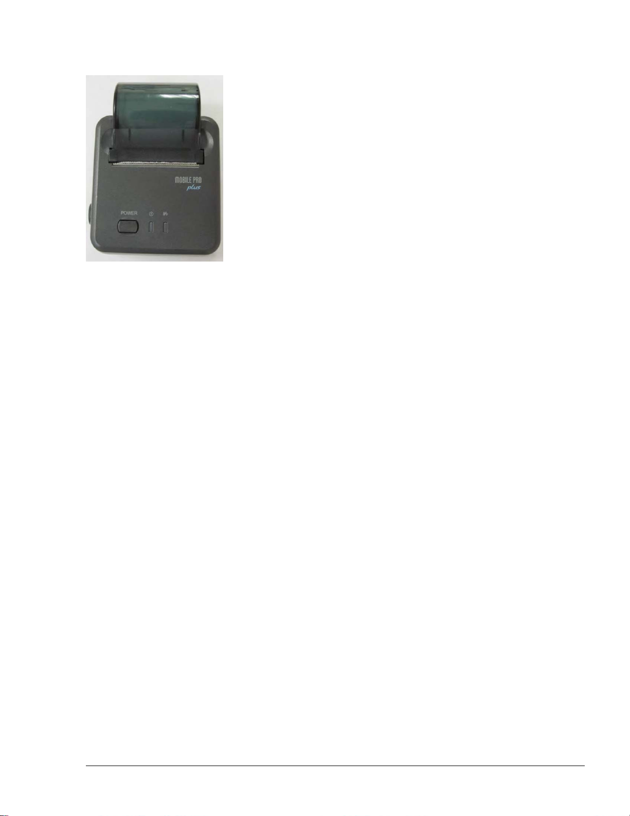
Figure 4-1. Mobile Printer – Main Components............................................................................... 58
Figure 4-2. Printer Harnesses ........................................................................................................... 60
Figure 4-3. OrCUAdministrator – Serial/Modem Settings Screen ................................................... 61
Figure 4-4. OrCUAdministrator – System Information Screen ........................................................ 62
Figure 4-5. SiteOmat – Buses Dialog Box ....................................................................................... 63
Figure 4-6. SiteOmat – Printers Dialog Box..................................................................................... 64
Figure 4-7. Paper Roll Direction....................................................................................................... 65
Fuel Truck Controller Manual
Page 13

vii
LIST OF TABLES
Table
Page
Table 2-1. Conduits into Fuel Truck Controller ............................................................................... 31
Table 2-2. Fuel Truck Controller, Cables Type................................................................................ 32
Table 2-3. Fuel Truck Controller, Cables Routing ........................................................................... 33
Table 2-4. Nozzles to Fuel Truck Controller, Cables Routing ......................................................... 33
Table 3-1. Fuel Truck Controller, Installation Assembly Parts ........................................................ 40
Table 3-2. Fuel Truck Controller, Assembly Parts ........................................................................... 44
Table 3-3. Fuel Truck Controller Terminal Block - Mechanical Pump – Connections Definition .. 47
Table 4-1. Mobile Printer Specifications .......................................................................................... 59
Table 4-1. Fuel Truck Controller Troubleshooting ........................................................................... 66
Table 4-2. Communication Troubleshooting..................................................................................... 73
Fuel Truck Controller Manual
Page 14
8
0
11--11.. SSCCOOPPEE
11--22.. DDEESSCCRRIIPPTTIIOONN
SECTION 1
GENERAL DESCRIPTION
This manual is provided to assist you in installing – Gasboy’s Fuel Truck Controller. The system
must be installed as described in this manual to ensure the system reliability and proper operation.
This manual includes a general and functional description of the Fuel Truck Controller and its main
components. It also provides the installation procedures for the Fuel Truck Controller.
This manual is intended for qualified authorized installers of the Fuel Truck Controller and its
components.
Fuel Truck Controller is a fuel control and data acquisition system. Fuel Truck Controller system is
a self-contained weather-resistant cabinet installed on fuel trucks used as mobile refueling station.
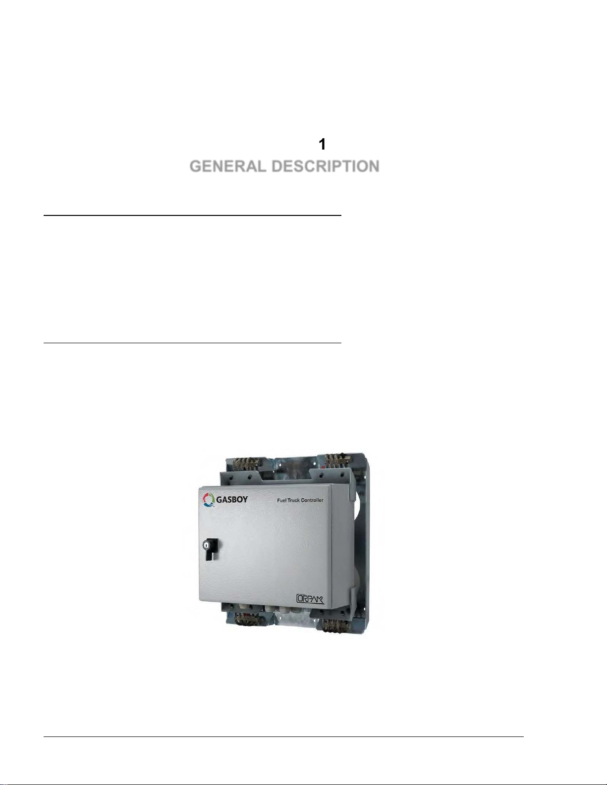
Fuel Truck Controller (see Figure 1-1) is a core component in Gasboy’s solution for mobile
refueling stations. Fuel Truck Controller provides the central function of the mobile site controller.
It also fulfills other essential services on site such as Vehicle/Driver Identification System,
Transaction data storage, devices control and more.
Figure 1-1. Fuel Truck Controller - General View with Shock Absorber Assembly
Fuel Truck Controller Manual
Page 15

9
11--33.. SSYYSSTTEEMM OOVVEERRVVIIEEWW
11--33..11.. FFuueell TTrruucckk CCoonnttrroolllleerr SSyysstteemm
11--33..22.. VVeehhiiccllee IIddeennttiiffiiccaattiioonn
11--33..33.. RReemmoottee WWeebb AAcccceessss
11--33..44.. FFlleeeett HHeeaadd OOffffiiccee
11--33..55.. RReessttrriiccttiioonnss aanndd LLiimmiittss
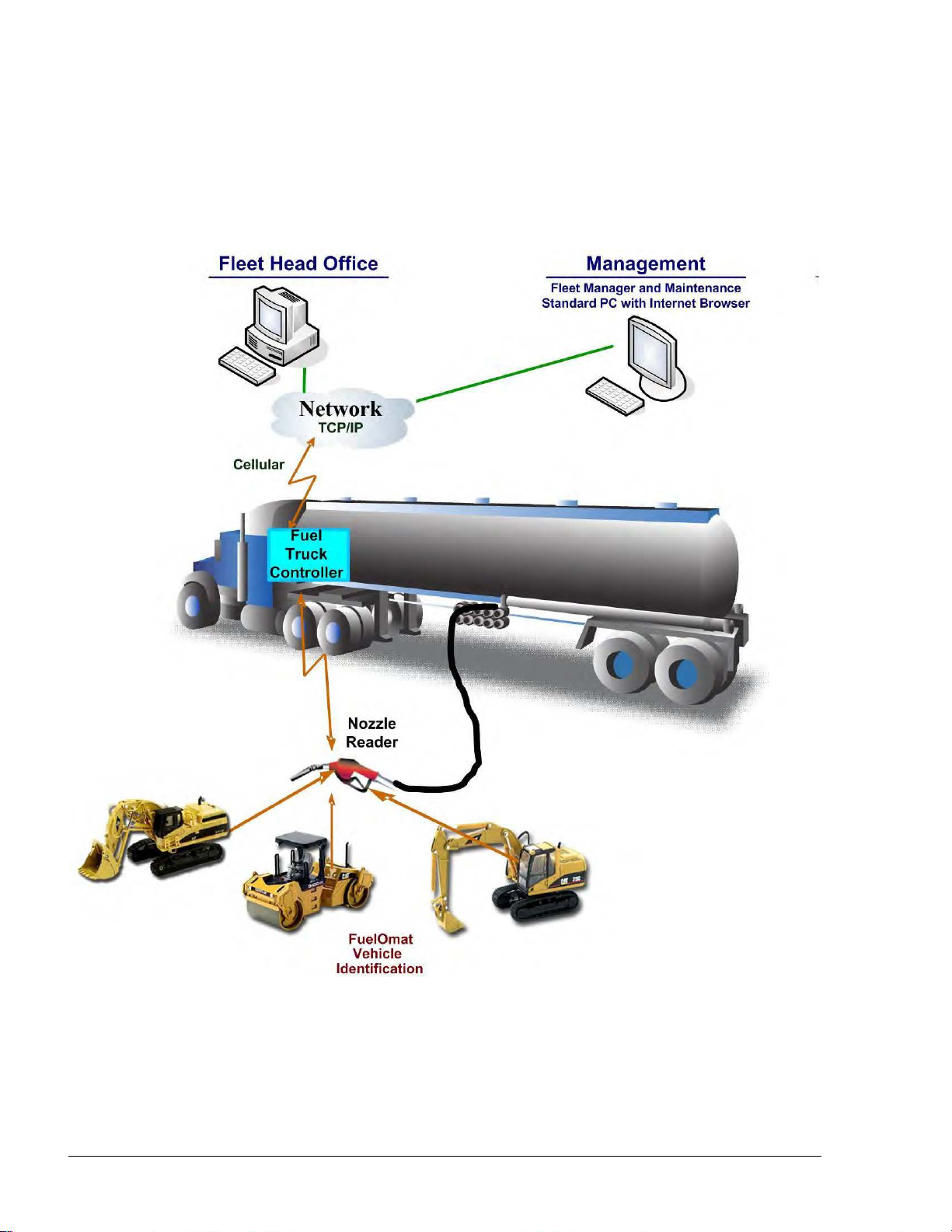
Fuel Truck Controller system is a mobile Fleet Management System. The system controls, monitors
and stores on-the-spot refueling data by tanker truck for customers with large land moving
equipment. The system is suitable for a large range of home base customers.
The system consists of a Controller mounted on the truck and Vehicle Identification Units (VIU)
installed on the fleet vehicles.
Fuel Truck Controller enables refueling of vehicles equipped with VIUs only. The vehicles fuel
inlet must be positioned in the proximity of the fuel pump nozzle, ensuring end-to-end
authentication of the vehicle, meaning that only authorized vehicles get fuel. After providing fuel,
the system registers the transaction data (see Figure 1-2).
The heart of the mobile solution is the Orpak Controller Unit (OrCU) operating with the SiteOmat
automation software. SiteOmat runs on an embedded operating system. OrCU is a hardware
platform designed to survive the harsh gas station environment. It uses a solid state FLASH disk
and RTC (Real Time Clock) with back-up, along with surge suppressors for transients and noise
immunity. The system also includes power fail recovery mechanisms.
Vehicle Identification is an essential feature for maximal control and savings on fuel expenditure.
The dispenser is authorized to refuel after a positive identification of the vehicle and only while the
nozzle is inside the fuel inlet of the identified vehicle. All transaction information is automatically
recorded. A combined vehicle and driver identification is also possible for tight tracking.
Remote Web-based capabilities for monitoring, management and maintenance are available. A
standard PC with Internet Browser (Explorer) is used for remote management of Fuel Truck
Controller. There is no need for special purpose management software thanks to the built-in Web
server technology integrated into Fuel Truck Controller.
Centralized management is provided by the optional Fleet Head Office server. The Fleet Head
Office consolidates the data from multiple sites and generates reports, including exception reports.
It also enables control of the limits and restrictions placed on the various fleet vehicles.
Furthermore, authorized fleet personnel are able to log-in remotely and are always in control.
Control of a fleet’s fuel consumption can be maximized by defining limits. Optional limits include:
volume per day/week/month, fuel type. In case of communication failure, the specific site will be
able to refuel for a predefined grace period (parameter) using the most recent limits stored in its
database.
Fuel Truck Controller Manual
Page 16
10
11--33..66.. FFuueell TTrruucckk CCoonnttrroolllleerr CCaappaabbiilliittiieess ffoorr MMoobbiillee SSttaattiioonn MMaannaaggeemmeenntt
The Fuel Truck Controller provides features for a comprehensive mobile refueling station
management by enabling a large variety of communication links: Cellular, dial-in modem, WiFi,
radio modem and satellite.
Figure 1-2. Fuel Truck Controller on a Fuel Truck - General Configuration Diagram
Fuel Truck Controller Manual
Page 17

11
11--33..77.. SSyysstteemm WWoorrkkffllooww -- EExxaammppllee
An example of an operational workflow for self-service at the Fuel Truck Controller site is provided
below:
The Fuel Truck Controller equipped fuel truck arrives at the construction site to refuel its fleet
vehicles. All fleet vehicles equipped with FuelPoint PLUS devices. The operator inserts the nozzle
into a vehicle fuel inlet and waits for authorization. Truck data is automatically read and stored in
the Controller for authentication and authorization. Upon approval, the fueling transaction starts, at
the end of which the transaction data is kept internally until transferred to the Head Office (HO) for
future billing.
Fuel Truck Controller Manual
Page 18
12
11--44.. FFUUEELL TTRRUUCCKK CCOONNTTRROOLLLLEERR SSTTRRUUCCTTUURREE
11--44..11.. MMaaiinn CCoommppoonneennttss
Following is a short description of the Fuel Truck Controller main sub units:
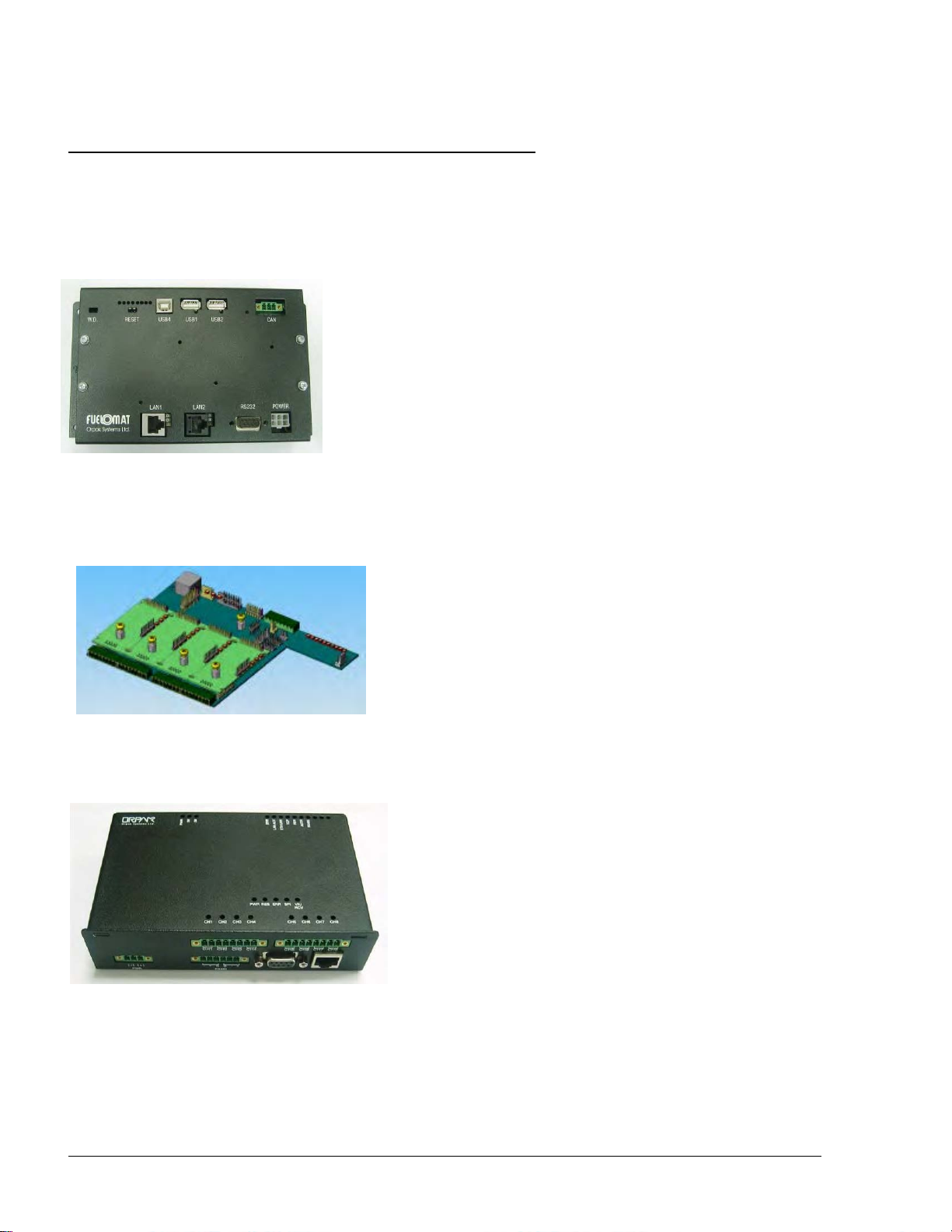
Orpak Controller Unit (OrCU)
Orpak Controller Unit (OrCU) is a complete controller with its
own embedded operating system. The unit consists of an
embedded hardware platform with a solid state Flash hard disk,
Real Time Clock (RTC) with backup, along with surge
suppressors for transient and noise immunity
It features two separate and isolated networks (TCP/IP over
Ethernet). One network links the Fuel Truck Controller system
components. The second network is intended for external
remote communication (Head Office, 3rd party systems). This
network is protected by SSL security.
OrCU includes a built-in server for Web access trough an internet browser (Explorer).
8-Port CommVerter
The 8-Port CommVerter is the communication interface
to the peripheral pumps. It consists of communication
modules for the mechanical pump elements. The
CommVerter includes one MPI-C card and sub card for
interface to two mechanical pumps, an Ethernet Switch.
The CommVerter communicates with the Site Controller
(OrCU) via a LAN (Ethernet) link.
Micro Vehicle Identification Transceiver (uVIT) (Optional):
The uVIT reads Orpak’s vehicle identification
components through the VIRO Receivers (Receiver
coil) installed on the hose nozzle equipment. The uVIT
supports up to eight VIRO Receivers. The connection
to the VIRO receiver must be done through an
intrinsically safety barrier. The uVIT performs the first
level of authentication by decrypting the string
transmitted from the vehicle. As an option for several
applications, the uVIT includes some capabilities for
peripheral equipment interface.
The uVIT is connected to the system via a LAN (Ethernet) link.
Optional Mobile Printer
Fuel Truck Controller Manual
Page 19
13
Fuel Truck Controller includes an optional Mobile Printer. Installed in
the driver's cabin and directly connected to the Controller Unit viva
RS-232 link, this compact device prints out all fueling transactions.
The Mobile Printer includes two LED indicators on the front panel:
Green: Power On
Red: Out of paper
Fuel Truck Controller Manual
Page 20
14
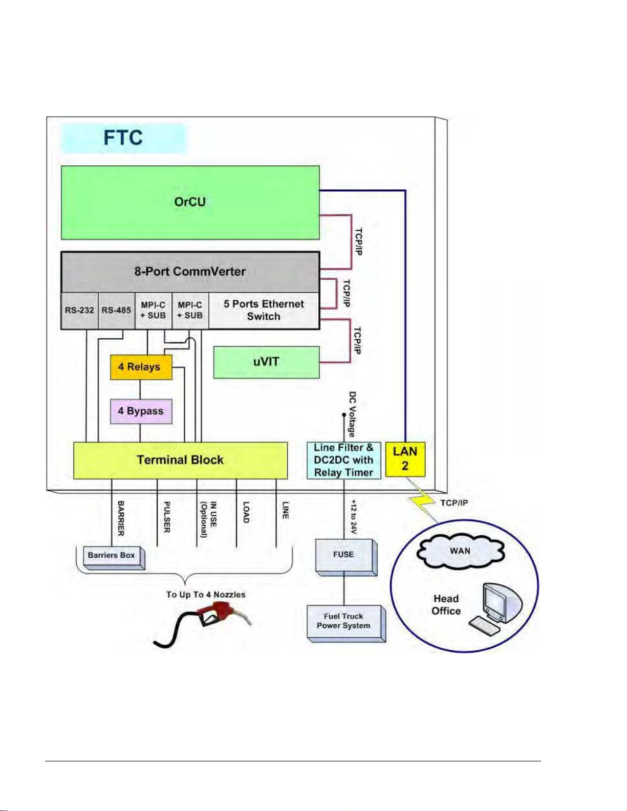
11--44..22.. FFuueell TTrruucckk CCoonnttrroolllleerr GGeenneerraall CCoonnffiigguurraattiioonn
Figure 1-3 shows a general configuration diagram of Fuel Truck Controller.
Figure 1-3. Internal Configuration Diagram – Mechanical Pump
Fuel Truck Controller Manual
Page 21
15
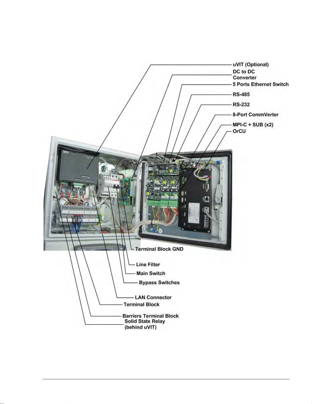
11--44..33.. FFuueell TTrruucckk CCoonnttrroolllleerr MMaaiinn CCoommppoonneennttss LLooccaattiioonn
Figure 1-4 shows the location of the main components of Fuel Truck Controller.
Figure 1-4. Fuel Truck Controller Internal Components Location
Fuel Truck Controller Manual
Page 22

16
11--55.. AAVVAAIILLAABBLLEE CCOONNFFIIGGUURRAATTIIOONNSS
11--55..11.. GGeenneerraall
11--55..22.. VVeehhiiccllee IIddeennttiiffiiccaattiioonn SSyysstteemm –– FFuueellPPooiinntt PPLLUUSS
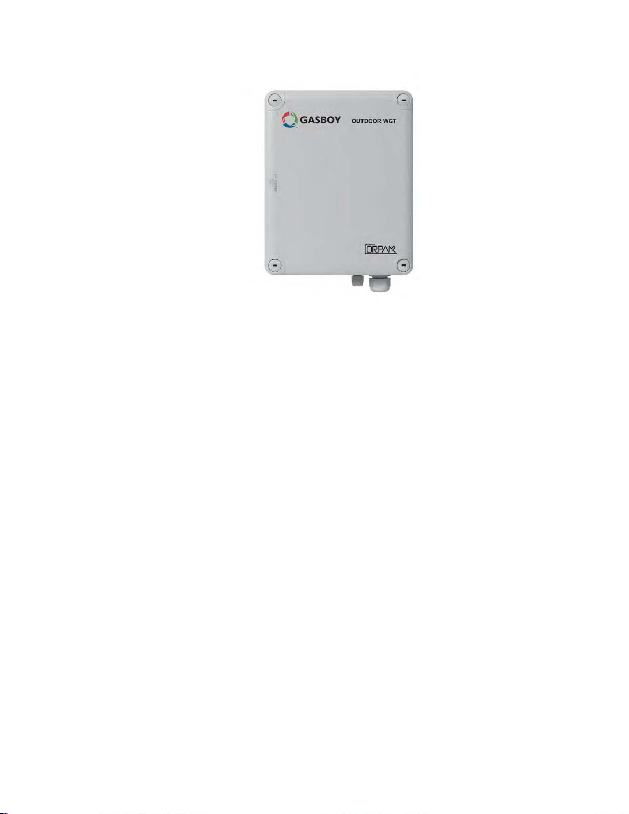
11--55..33.. WWGGTT EExxtteerrnnaall BBooxx –– OOppttiioonnaall
The Fuel Truck Controller is available in several configurations, in accordance with its intended use
and with the components installed. All configurations are manufactured in accordance with specific
customer request.
The following paragraphs describe the several configurations, and their devices composition.
The following options are available for vehicle identification:
Wireless Gateway Terminal (WGT) – with this terminal, the vehicle identification process
is performed in a wireless mode.
Micro Vehicle Identification Transceiver (uVIT) – Orpak’s wired vehicle authorization
system.
No vehicle identification unit: The vehicle identification process will be done manually by
the truck driver with any accepted authorization devices such as cards, or tags. This option
will require external tag reader connected to Fuel Truck Controller (refer to paragraph1-5.6).
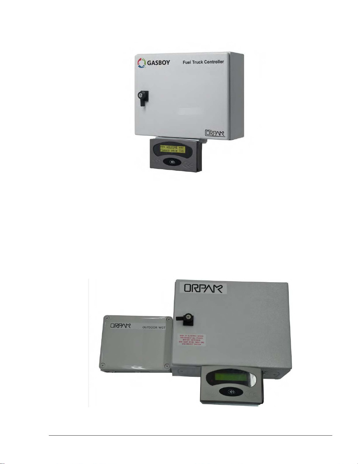
The Wireless Gateway Terminal (WGT) receives DataPass, FuelOpass and VIU signals, decrypts
their information and transmits it to the Station automation system (OrCU) in a secure manner over
an RF signal. This setup enables the RF signal to travel through various routes and bypass possible
interferences (such as a big truck/bus). The transmission signal range is 10 meters.
The WGT is designed to be installed in a designated external box on the truck on the side facing the
fueling elements. The WGT will be connected to the Fuel Truck Controller box using CAT5E
cable. More than one WGT external boxes can be mounted on one truck for better RF area
coverage. In this case one WGT box will be Master and the other(s) will be routers. For further
details, see WGT External Installation Guide, document no. MDE-4815
Fuel Truck Controller Manual
Page 23
17
11--55..44.. SSaaffeettyy BBaarrrriieerrss
Figure 1-5. Wireless Gateway Terminal (WGT)
The units that provide data to the WGT are:
DataPass - DataPass is a miniature unit that connects to the vehicle bus and captures data
from the vehicle CPU/BUS. It then transmits this data to the nearest Wireless Gateway
Terminal (WGT) in the forecourt.
FuelOpass - FuelOpass is a passive vehicle identification tag for refueling. Its encrypted
data includes the account to be charged and is read by the Nozzle Reader device using RFID
contactless technology.
VIU - VIU is an active Vehicle Identification Unit for refueling. The data includes odometer
and engine hour meter.
Nozzle Reader (NR) - Nozzle Reader is a self contained unit installed on the nozzle which
reads the FuelOpass data using contactless technology.
To obtain maximal grid availability, several WGT units can be installed to create a robust 'mesh'
network.
Safety Barriers are required in the truck whenever the Fuel Truck Controller includes an uVIT.
uVIT is electrically connected to the transceiver coil of the nozzle. This coil is intended for use in
potentially explosive atmosphere. Therefore the connection between these devices must be done
via an intrinsically safe barrier. Consequently, the truck must be equipped with an external Barriers
Box. The barriers in use depend on the geographical location of the installation:
Barriers and nozzle rings must be installed on dispensers as UL Listed by Report Retrofit
kits prior to the installation of the Fuel Truck Controller.
P/N 808012500 Barrier4 (Atex – For all regions except North America)
Fuel Truck Controller Manual
Page 24
18
11--55..55.. MMooddeemm//RRoouutteerr
11--55..66.. EExxtteerrnnaall TTAAGG RReeaaddeerr ((OOrrTTRR))
Please consult your local cellular service provider for the type of router supported in your area. The
router will be provided from your service provider with proper installation instructions. The router
will be connected to the LAN input in OrCU box.
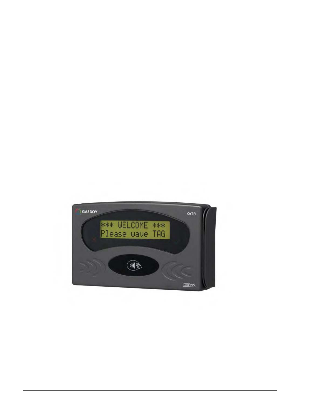
OrTR (P/N 800910910) - OrTR (Orpak Tag Reader) receives Orpak tag signals for refuel
authorization purpose. OrTR transmits the information to the Station automation system (OrCU)
over a CAT5E or RS-485 cable. OrTR contain LCD with 2 lines display. OrTR is designed to be
installed in a non hazardous, convenient and secured area in accordance with local state regulations.
In the vehicle two installation alternatives are available:
External box in any non hazardous area. This installation mode requires a dedicated
mounting bracket. Such an installation shall be performed within safety distances required
for any installation adjacent to dispensers.
Installed beneath Fuel Truck Controller box with mounting bracket (P/N 814930300)
For further details, see OrTR Installation Guide, document no. MDE - 4816.
Figure 1-6. Tag Reader (OrTR)
Fuel Truck Controller Manual
Page 25
19
Figure 1-7. Fuel Truck Controller with OrTR
11--55..77.. FFuueell TTrruucckk CCoonnttrroolllleerr wwiitthh OOrrTTRR aanndd WWGGTT
In this configuration (see Figure 1-8), the Fuel Truck Controller encompasses most types of
authorization devices. The Wireless Gateway Terminal (WGT) provides vehicle identification
process in wireless mode while Orpak Tag Reader (OrTR) reads Orpak tag signals to complete any
transaction.
WGT communicates with Fuel Truck Controller over the LAN (CAT5E cable) and is powered
directly by Fuel Truck Controller. RF transmission of data from WGT enables sending data of all
transactions to the Station controller.
Figure 1-8. Fuel Truck Controller with OrTR and WGT
Fuel Truck Controller Manual
Page 26

20
11--55..88.. FFuueell TTrruucckk CCoonnttrroolllleerr -- SSttaannddaarrdd MMooddeellss
Table 1-1. Fuel Truck Controller - Standard Models
Name
Gilbarco P/N
Orpak P/N
Fuel Truck Control Unit for 2 hose
PA039600200
800938901
Fuel Truck Control Unit for 4 hose
PA039600400
800938902
Table 1-1 define all the available product numbers for the different configurations of Fuel Truck
Controller:
Fuel Truck Controller Manual
Page 27

21
11--66.. SSEECCUURRIITTYY AANNDD PPRROOTTEECCTTIIOONN
11--66..11.. GGeenneerraall
11--66..22.. AAuutthhoorriizzaattiioonn SSeeccuurriittyy
11--66..33.. NNeettwwoorrkk SSeeccuurriittyy
11--66..44.. RRFF NNeettwwoorrkk SSeeccuurriittyy
11--66..55.. MMaaiinntteennaannccee SSeeccuurriittyy
11--66..66.. RRTTCC BBaacckkuupp
11--77.. HHOOUUSSIINNGG
The transaction activities of the Fuel Truck Controller are secured and protected for transmission
and authorization activities.
The contact-less tags include Triple DES encrypted data for user identification and billing.
Consequently, the Fuel Truck Controller includes a special Security Application Module (SAM) for
decryption and matching identification. Upon tag reading, the Fuel Truck Controller attempts to
decrypt the string from the tag. The Fuel Truck Controller disregards Tags whose security scheme
does not match the Fuel Truck Controller internal SAM.
The Ethernet LAN is isolated from the external WAN by the Site Controller (OrCU). In case of
remote maintenance, a firewall should be applied either at the router level or preferably at the Home
Base Station level.
The Fuel Truck Controller EIA 802.15.4 RF network is encrypted, using the AES 128 security
standard.
The Fuel Truck Controller maintenance and setup procedures require inserting a user name and
password for access. For further information, please refer to the SiteOmat station controller Setup
Manual, P/N MDE-4817
Fuel Truck Controller is locked by key to prevent unauthorized access to the bypass switches and
controller electronics.
The Real Time Clock backup is based on a maintenance free 1 Farad supercapacitor. Backup time is
3 to 6 days before time and date loss.
Fuel Truck Controller enclosure is a weather-proof metal cabinet, able to sustain the harsh
environment of the Island. The Fuel Truck Controller is installed with a rear shock absorber
assembly that dampens vibrations from truck and road (see Figure 1-9).
The overall structure is installed vertically on any flat surface and secured with eight screws. See
anti-vibration shock absorbers in Figure 1-10.
Fuel Truck Controller is locked by key for safety and security. The key should be kept in a wellkept, secure and safe place.
Fuel Truck Controller Manual
Page 28

22
We recommend installing the Fuel Truck Controller box in the truck cabin or any other protected
compartment on the truck. Any installation should provide convenient access for service and
maintenance.
Figure 1-9. Fuel Truck Controller - General View with Shock Absorber Assembly
Figure 1-10. Shock Absorber - Detail
Fuel Truck Controller Manual
Page 29

23
11--88.. SSPPEECCIIFFIICCAATTIIOONNSS
Supply Voltage:
12 – 24 VDC
Power Consumption:
2.6A max.
Operating Temperature:
-22 F to +104 F (-30 C to +40 C)
Storage Temperature:
-22 F to +104 F (-30 C to +40 C)
Humidity:
80% Non-condensing
Dimensions:
- Box without Shock Absorber
Assembly:
Box with Shock Absorber
Assembly:
W x H x D: 15 x 11.80 x 6.10 "
(380 x 300 x 155 mm)
W x H x D: 16.50 x 18.10 x 7.90 "
(420 x 460 x 200 mm)
Communication Interface:
RS-485 – 9600 bps, Half-Duplex
RS-232
Ethernet RJ-45 - 10 Mbps
Valve Control Maximum Current
(4 Solid State Relay Channels):
12 V / 2A , 24V / 1A
Pulser power supply voltage
12 VDC / 30 mA max
Pulser Input High level voltage
Pulser Input High level sink
current (@15V)
9 to 15 VDC
3 mA
In use "On" level (Input)
Dry contact only (5V/1mA maximum)
11--99.. SSTTAANNDDAARRDDSS
11--99..11.. CCoommmmuunniiccaattiioonn SSttaannddaarrddss
The following physical, electrical and environmental specifications are applicable to the Fuel Truck
Controller:
The Fuel Truck Controller communicates, in its different models, over the following standards:
RS-485 link
TCP/IP over Ethernet
EIA 802.15.4
Fuel Truck Controller Manual
Page 30

24
11--99..22.. SSeeccuurriittyy SSttaannddaarrddss
Triple DES encryption for Payment Devices (Contact-less tags, magnetic stripe cards, etc.)
Fuel Truck Controller Manual
Page 31

25
11--1100.. MMAANNUUAALL SSTTRRUUCCTTUURREE
This manual comprises of the following sections:
Section 1: General Description
This section provides a general description of the Fuel Truck Controller system.
Section 2: Preliminary Installation Procedures
This section provides the preliminary installation requirements and procedures to be performed
before installing Fuel Truck Controller.
Section 3: Installation Procedures
This section provides a detailed description of Fuel Truck Controller installation requirements and
procedures.
Section 4: Maintenance
This section provides basic maintenance instructions for the Fuel Truck Controller.
Section 5: Glossary
This section includes a glossary of terms used for the Fuel Truck Controller description.
Appendix A: Wiring Diagram
This appendix includes the Wiring Diagram of the Fuel Truck Controller.
Appendix B - Site Survey Form – Example
This appendix includes an example of a form to be filled during a Site Survey. You may add or
remove parts of the questionnaire in order to fit it to your customer working environment.
Fuel Truck Controller Manual
Page 32

26
11--1111.. UUSSIINNGG TTHHIISS MMAANNUUAALL
This manual includes alerting comments inserted along the document, in order to draw the reader’s
attention to important issues. The comments are accompanied by symbols for ease of reference.
The following comment types are used:
WARNING
An operating procedure, practice, etc., if not
correctly followed, could result in injury or loss of
life.
CAUTION
An operating procedure, practice, etc, if not strictly
observed, could result in damage to, or destruction
of equipment.
TIP
This note is aimed for using the system in better
efficiently way.
NOTE
This comment is of importance for emphasizing.
INSIGHT
More detailed technical/ functional information in
regard relevant issue.
Fuel Truck Controller Manual
Page 33

27
11--1122.. RREEFFEERREENNCCEESS
For additional and complementary information regarding the Fuel Truck Controller system, please
refer to the following manuals:
uVIT Installation and Operation Manual, Document No. 817412300
8-Port CommVerter User’s Manual, Document No. MDE-4812
WGT outdoor unit Installation Guide, document no. MDE-4815.
OrTR Installations guide, document no. MDE-4816.
SiteOmat Station Controller User’s Manual, Document No. MDE-4817
SiteOmat Station Controller Setup Manual, Document No. MDE-4818
Fuel Truck Controller Manual
Page 34

28
0
22--11.. GGEENNEERRAALL
22--22.. PPRREELLIIMMIINNAARRYY IINNSSTTAALLLLAATTIIOONN IINNSSTTRRUUCCTTIIOONNSS
22--22..11.. GGeenneerraall
SECTION 2
PRELIMINARY INSTALLATION INSTRUCTIONS
This section provides the preliminary installation procedures for Fuel Truck Controller. These
instructions shall be performed in order to ready the fuelling truck to the installation of Fuel Truck
Controller.
These procedures include:
Preliminary installation instructions
Wiring and Wire Conduits requirements
Installation procedures and requirements depend, to some extent, on the specific fuel dispenser
models and the fuel truck layout. Therefore, use the information in this section to develop
installation plans for each specific installation. Since installation requirements vary widely from
case to case, no installation hardware is supplied by the equipment manufacturer, and installation
planners must develop their own requirements.
NOTE
Perform a truck survey prior to installation.
Refer to Appendix B "Site Survey Form".
The customer should provide an installation plan, designed by an authorized engineer, and
applicable to all authorities. This plan design should reflect the existing electric infrastructure of
the site.
Fuel Truck Controller Manual
Page 35

29
22--22..22.. PPrreeccaauuttiioonnss aanndd SSaaffeettyy NNootteess
22--33.. CCOONNDDUUIITTSS IINNSSTTAALLLLAATTIIOONN
22--33..11.. GGeenneerraall
22--33..22.. CCoonndduuiitt RReeqquuiirreemmeennttss
Prior to actual installation activities, carefully observe the precautions and safety notes below.
WARNING
Before installing or servicing equipment, carefully
observe the warnings and precautions provided at
the beginning of this manual.
Remember that the fuel truck environment is highly flammable and combustible.
Therefore, make sure that actual installation is performed by experienced personnel,
licensed to perform work in fuel trucks and capable of implementing all applicable
requirements of the National Fire Protection Association NFPA-30 “Flammable and
Combustible Liquids Code”, NFPA-30A “Code for Motor Fuel Dispensing Facilities and
Repair Garages”, NFPA-70A “National Electric Code”, federal, state and local codes and
any other applicable safety codes and regulations.
System power may come from more than one source. Disconnect all power sources before
attempting to work on the system.
Install the Fuel Truck Controller only in non-hazardous locations, in an area in accordance
with the safety restrictions.
Fuel Truck Controller site preparation is in the customer’s responsibility.
Do not connect power to the Fuel Truck Controller until complete installation is inspected
and certified.
Do not perform any metal work in the hazardous area. Sparks generated by drilling,
tapping and metal work operations could ignite fuel vapors and flammable liquids, resulting
in death, serious personal injury, property loss and damage to you and other persons.
The installation of the Fuel Truck Controller requires setting several conduits in the fuel truck. The
conduits are required for the routing and protection of the different types of cables.
The installation of the Fuel Truck Controller requires preparing beforehand the conduits and cables
layout in the fuel truck. This procedure consists of
Installing conduits within the truck,
Inserting the proper cables
Connecting to power.
Conduits must comply with the following requirements:
Conduits should be installed in accordance with local regulations.
Fuel Truck Controller Manual
Page 36

30
It is recommended to use metal conduits (preferably Vx metal) to provide the necessary
22--33..33.. TTyyppee ooff CCoonndduuiittss iinn tthhee TTrruucckk
shielding and protection.
Conduits should be inserted in the Fuel Truck Controller through openings provided in the
bottom plate (see Figure 2-1). Connect the wiring through optional glands or appropriate metal
tubing. For UL/cUL listing, this product has only been evaluated for use without the optional
glands.
(*) All glands in picture are optional
Figure 2-1. Fuel Truck Controller Wiring Openings
The types of conduits in the truck are a function of the different equipment and their location in the
truck. The following conduits are required in the Fuel truck:
Voltage conduits
o DC power for Fuel Truck Controller
o Pump control from pumps to Fuel Truck Controller
o Pump In-use signal from pumps to Fuel Truck Controller
Communication conduits
o Pulser from pumps to Fuel Truck Controller
o Barriers/Coils from pumps to Fuel Truck Controller – Non-Intrinsically safe
wiring (NIS). Barriers may be enclosed in a special, separate Barriers Box.
Power conduit
o Fuel Truck Controller is fed from the truck power system, after the ignition
switch. Conduits of power cable should be done in accordance with local practice.
NOTE
Barriers Box is not provided with Fuel Truck
Controller.
Fuel Truck Controller Manual
Page 37

31
22--33..44.. WWiirriinngg OOppeenniinnggss iinn FFuueell TTrruucckk CCoonnttrroolllleerr
Table 2-1. Conduits into Fuel Truck Controller
No.
Conduit Type
Type
1
Low voltage
Pulser, Barrier
2
Voltage
DC power
3
Voltage
Control, In-use
22--33..55.. CCoonndduuiittss IInnssttaallllaattiioonn PPrroocceedduurreess
22--44.. CCAABBLLEESS
22--44..11.. GGeenneerraall
Fuel Truck Controller includes several wiring openings to carry specific wires, as listed in
Table 2-1 and shown in Figure 2-1.
Proceed as follows:
1. Determine the location of the Fuel Truck Controller in the fuel truck.
2. Install a junction box close to the valve for valve control.
3. Install a junction box for the pulser and nozzle antenna.
4. Deploy two conduits from the junction boxes to the Fuel Truck Controller (pulser, valve and
nozzle antenna).
5. Deploy a conduit from truck power system to Fuel Truck Controller. Fuel Truck Controller
is fed from the truck power system, after the ignition switch.
This paragraph describes the requirements and procedures for the insertion of cables in the conduits.
Fuel Truck Controller Manual
Page 38

32
NOTE
22--44..22.. CCaabbllee TTyyppeess
Table 2-2. Fuel Truck Controller, Cables Type
No.
Function
Type
1
Power supply and valve control
As used in vehicles 1.5 – 2.5 mm²
(15 to 13 AWG)
2
Coil (Barrier)
Data communication cable, 300 V RMS,
90ºC, shielded twisted pair, oil
resistant, 24 AWG, low capacitance
below 60 PF/meter similar to Belden
9729 cable
3
Pulser and In-use signal
4
LAN
CAT5E, Shielded , 300 V RMS, 90ºC
similar to Belden 121700A
5
GND
Ground cable 0.4" (10.8 mm2)
22--44..33.. CCaabblleess RRoouuttiinngg
The type of required cable varies in accordance with
the device it connects. The wire used must be
stranded and not a solid core. Select a cable
specification in accordance with local environment
conditions.
CAUTION
For supply connections, use wires suitable for at
least 90°C.
Signal wiring connected in this box must be rated at
least 300 V
Table 2-2 lists the types of cables used for the wiring of the Fuel Truck Controller system.
Connections should be done through a junction box (4x4x4" (10x10x10 cm)) located near
peripherals.
Route the cables from peripherals to Fuel Truck Controller as listed in Table 2-3 and Table 2-4.
Proceed as follows:
Fuel Truck Controller Manual
Page 39

33
Table 2-3. Fuel Truck Controller, Cables Routing
No.
Functional
Description
From
To
Cable Type
(*)
1
DC Power
DC to DC voltage
converter
Fuel Truck Controller box
terminal block
1
2
LAN
Low voltage junction box
4
3
Pulser
Fuel Truck
Controller box
Meter register, Pulser
3 4 Valve control
Valve
Fuel Truck Controller box
terminal block
1
Route cables from the nozzles to Fuel Truck Controller through a Barriers box. Proceed as follows:
Table 2-4. Nozzles to Fuel Truck Controller, Cables Routing
No.
Functional
Description
From
To
Cable Type
(*)
1
Nozzle antenna
Junction box
Barriers box
2
2
Barriers
Barriers box
Fuel Truck Controller
terminal block
2
22--55.. EElleeccttrriiccaall SSyysstteemm
22--55..11.. EExxtteerrnnaall FFuussee
22--55..22.. FFuueell TTrruucckk CCoonnttrroolllleerr PPoowweerr SSyysstteemm
(*) Refer To Table 2-2.
The Fuel Truck Controller requires an external fuse. Additional vehicle type 6 Amp fuse should be
installed between the truck's power supply system and the Fuel Truck Controller.
SAFETY CAUTION
The fuse should link the wire very close to the
battery, and at the distribution point (via a
distribution block).
The truck's power supply system is connected to the terminal block in the Fuel Truck Controller.
The system uses a Line Filter between the terminal block and the main switch in order to attenuate
conducted interference. The Line Filter is coupled with Timer relay, this timer provides 30 seconds
delay between power-feed and power output. This delay protects against short bursts of power
when the driver starts the truck. The delay is reset at each starting attempt. Consequently, Fuel
Fuel Truck Controller Manual
Page 40

34
Truck Controller is turned on 30 seconds after the truck is powered, when the motor should be
22--66.. GGRROOUUNNDDIINNGG AANNDD SSHHIIEELLDDIINNGG
operating steadily.
Fuel Truck Controller does not include a power switch.
Figure 2-2 Power Supply – Block Diagram
Proper system grounding is an extremely important part of the system installation. As with the DC
power, the grounds for all system components should return to the same circuit breaker panel. This
helps you assure a common ground throughout the system, necessary for protection of the RS-485
data loop circuitry.
The Fuel Truck Controller box is shielded through its installation screws to the vehicle chassis.
Fuel Truck Controller includes several grounding studs in order to comply with requirements. The
DC power ground wire should be attached to the stud close to the Line Filter.
Each shielded cable connected to the Fuel Truck Controller is stripped of its shielding at the box
entry. Its shield wires are bundled together at the entrance of the box and attached to a shielding
stud within the Fuel Truck Controller box. Figure 2-3 shows a functional diagram of the shielding.
Figure 2-3 Cables Shielding
Fuel Truck Controller Manual
Page 41

35
22--77.. CCOONNNNEECCTTIIOONNSS TTOO FFUUEELL TTRRUUCCKK
CCOONNTTRROOLLLLEERR
Most connections to the Fuel Truck Controller are performed to the Terminal Block located at the
bottom of the box (see Figure 2-4). The required connections are:
1. Pump wiring connections:
Pulser
Valve
In use (Optional, not existing in most cases)
2. Communications:
RS-485 for peripheral device
3. Power
DC Power to Line Filter
4. Other connections, not to the Terminal Block:
LAN connection
(*) All glands in picture are optional
Figure 2-4 Fuel Truck Controller Terminal Block, Power and LAN Connections
Fuel Truck Controller Manual
Page 42

36
Fuel Truck Controller Manual
Page 43

37
0
33--11.. GGEENNEERRAALL
33--22.. IINNSSTTAALLLLAATTIIOONN SSPPEECCIIFFIICCAATTIIOONNSS
33--22..11.. GGeenneerraall
33--22..22.. PPrreeccaauuttiioonnss aanndd SSaaffeettyy NNootteess
SECTION 3
INSTALLATION PROCEDURES
This section provides the installation procedures for the Fuel Truck Controller.
These procedures include:
Fuel Truck Controller installation
Wiring
Post installation check.
Installation procedures and requirements depend, to some extent, on the specific fuel truck and its
mechanical and electrical layout. Therefore, use the information in this section to develop an
installation plan for each specific installation. Since installation requirements vary widely from
case to case, no installation hardware is supplied by the equipment manufacturer, and installation
planners must develop their own requirements.
NOTE
Perform a site survey of the fuel truck prior to
installation
The customer should provide an installation plan, designed by an authorized engineer. This plan
design should reflect the existing electric infrastructure of the fuel truck.
Prior to actual installation activities, carefully observe the precautions and safety notes detailed in
paragraph 2-2.2 and at the opening pages.
Fuel Truck Controller Manual
Page 44

38
33--33.. FFUUEELL TTRRUUCCKK -- OOVVEERRVVIIEEWW
33--33..11.. GGeenneerraall
Prior to installation, you are required to obtain an overview of the fuel truck functional architecture.
This overview is required in order to draw an architecture diagram with all components and their
communication links.
Figure 3-1 shows a functional diagram of the links within the fuel truck with mechanical pump.
Figure 3-1. Fuel Truck Controller with Mechanical Pumps – System Diagram
Fuel Truck Controller Manual
Page 45

39
33--44.. MMAAPPPPIINNGG TTHHEE TTRRUUCCKK
33--44..11.. GGeenneerraall
33--44..22.. LLooccaattiinngg aallll oobbjjeeccttss ooff tthhee ffuueell ttrruucckk
33--44..33.. AAssssiiggnniinngg LLooggiiccaall IIDDss
The mapping of the fuel truck is required prior to installation. This procedure consists of the
following steps.
Locate installation of related objects in the fuel truck
Locate the intended position of the Fuel Truck Controller
Draw a basic map of the site with all the objects
Logical IDs should be assigned to the Pump and Nozzle:
Assign an id. to the pump (P)
Assign an id. to its nozzle (N)
Fuel Truck Controller Manual
Page 46

40
33--55.. IINNSSTTAALLLLIINNGG TTHHEE FFUUEELL TTRRUUCCKK CCOONNTTRROOLLLLEERR
33--55..11.. IInnssttaallllaattiioonn AAsssseemmbbllyy PPaarrttss
Table 3-1. Fuel Truck Controller, Installation Assembly Parts
Item No.
Part Number
Description
Qty
1
800938901
(PA039699200)
Fuel Truck Controller
1
2
819040120
(M09680B039)
Shock Absorber Assembly
1
3
815216200
Pan head screw, M6 x16
8
4.
815322200
Flat Washer, M6
8
5
815303100
Spring Washer, M6
8
6
815222000
M8 x 20 mm Hex bolt (*)
4
7
815305500
Washer, Flat, M8
4
8
815122000
Nut, M8
4
9
814605600
(M09680B035)
Shock absorber
4
10
814979800
Plate, shock absorbers
4
The Fuel Truck Controller can be installed in two configurations:
a. Installation of Fuel Truck Controller only
This type of configuration is designed for installing the Fuel Truck Controller in locations
such as inside truck cabins, that are not exposed to the harsh environment and thus do not
require shock absorbers.
b. Installation of Fuel Truck Controller with Shock Absorber Assembly
This type of configuration is designed for installation of the Fuel Truck Controller in
vehicles (not in driver's cabins) in areas of the vehicle that are exposed to the harsh
environment which need shock absorbers.
For installation of the Fuel Truck Controller with Shock Absorber Assembly, the client must
order the Shock Absorber Assembly (P/N 819040120) in addition to ordering the Fuel Truck
Controller (P/N 800938901).
Table 3-1 lists the assembly parts for the installation of the Fuel Truck Controller.
(*) Optional, for installing the Fuel Truck Controller to the Shock Absorber assembly.
Fuel Truck Controller Manual
Page 47

41
33--55..22.. PPrreelliimmiinnaarryy PPrroocceedduurreess
33--55..33.. FFuueell TTrruucckk CCoonnttrroolllleerr IInnssttaallllaattiioonn iinn DDrriivveerr''ss CCaabbiinn
33--55..44.. DDeetteerrmmiinniinngg tthhee SSppoott IInnssttaallllaattiioonn FFuueell TTrruucckk CCoonnttrroolllleerr wwiitthh SShhoocckk AAbbssoorrbbeerr
AAsssseemmbbllyy
For installation of Fuel Truck Controller only, the following procedures should be performed in
this order:
Installing the Fuel Truck Controller on the support rails in driver's cabin
Running cables through the conduits to Fuel Truck Controller
Wiring Fuel Truck Controller.
For installation of Fuel Truck Controller with the Shock Absorber Assembly, the following
procedures should be performed in this order:
Installing Shock Absorbers Assembly on support flanges in the selected area on the
truck
Installing the Fuel Truck Controller on Shock Absorbers Assembly.
Running cables through the conduits to Fuel Truck Controller
Wiring Fuel Truck Controller.
To install the Fuel Truck Controller in the driver's cabin, perform the following steps:
a. Look for the support rail at the back of the driver's cabin in the fuel truck. There are usually
two perpendicular rails.
b. Select the rail where installation is easier (less cluttered area)
c. Prepare beforehand two support flanges with two setting holes in each
d. Connect the Fuel Truck Controller through the internal four holes or through the wall mount
bracket to the support flanges.
e. Use dedicated drill screws for the installation to the support rails.
After the Fuel Truck Controller installation is completed, proceed with unit wiring according to
the instructions provided in paragraph 3-7.
Proceed as follows:
1. Look for a support rail at the selected installation location in the fuel truck.
2. Select the rail where installation is easier (less cluttered area)
3. Prepare beforehand two support flanges with two setting holes in each
4. Drill eight M6 Hex threads in the support flanges of the Shock Absorbers plate. See
location and dimensions in Figure 3-2 and Figure 3-3 (10 in Table 3-1)
5. Drill four Hex threads in the rails for the support flanges
6. Install the support flanges and secure with bolts, spring washers and flat washers
Fuel Truck Controller Manual
Page 48

42
33--55..55.. SShhoocckk AAbbssoorrbbeerrss AAsssseemmbbllyy -- IInnssttaallllaattiioonn PPrroocceedduurreess
The Shock Absorbers Assembly should be mounted on any flat surface on the truck. The rear
wall of the shock absorber assembly includes eight holding holes for support screws.
Proceed as follows:
1. Locate the eight installation holes on the mounting flanges (see Figure 3-2 and Figure 3-3)
2. Check that eight M6 Hex threads in the installation flange have been drilled
3. Set Shock Absorbers assembly (2 in Table 3-1)on the spot (see Figure 3-2) so that its
installation holes fit with the threads
4. Secure Shock Absorbers assembly with eight M6 Pan head bolts, M6 flat washers and M6
spring washers (3, 4, 5 in Table 3-1)
Figure 3-2 Shock Absorber Assembly – Installation Holes
Fuel Truck Controller Manual
Page 49

43
33--55..66.. FFuueell TTrruucckk CCoonnttrroolllleerr IInnssttaallllaattiioonn AAsssseemmbbllyy
Figure 3-3 Fuel Truck Controller with Shock Absorber Assembly – Installation Holes
Fuel Truck Controller box is secured to Shock Absorber Assembly from within Fuel Truck
Controller (see Figure 3-4).
Figure 3-4 Installing Fuel Truck Controller on Shock Absorber Brackets – Installation Holes
Proceed as follows:
Fuel Truck Controller Manual
Page 50

44
1. Install Fuel Truck Controller box on assembly on Shock Absorbers Assembly so that the
33--66.. IINNSSTTAALLLLAATTIIOONN OOFF FFUUEELL TTRRUUCCKK CCOONNTTRROOLLLLEERR WWIITTHH WWAALLLL MMOOUUNNTT KKIITT
33--66..11.. IInnssttaallllaattiioonn AAsssseemmbbllyy PPaarrttss
Table 3-2. Fuel Truck Controller, Assembly Parts
Item No.
Part Number
Description
Qty
1
800938901 to 800938932
Fuel Truck Controller
1 2 819022200
Wall Mount Kit
1
2a
814423100
Wall Bracket
4
2b
815122000
Nut M8
4
2c
815222000
Screw, M8x20, Hexagon Head
4
2d
815322000
Washer, Flat, M8
4
2e
815322100
Washer Spring M8
4
2f
815322400
Washer, Insulator, M8
4
33--66..22.. IInnssttaallllaattiioonn PPrroocceedduurreess
shock absorbers fit into place
2. Open Fuel Truck Controller box
3. Secure Fuel Truck Controller box to Shock Absorbers Assembly with four M8 Hex bolts,
four M8 flat washers, and four Nuts (6, 7, 8 in Table 3-1)
4. Perform Fuel Truck Controller wiring (refer to paragraph 3-7)
5. Lock Fuel Truck Controller box door with key.
Table 3-2 lists the assembly parts for the installation of the Fuel Truck Controller.
Proceed as follows:
Note: If the wall mount is already installed, go to step 4.
1. Open Fuel Truck Controller enclosure
2. Turn Fuel Truck Controller enclosure (1 in Table 3-2) so you face its rear panel (see
Figure 3-5)
3. Attach to each support hole in the rear panel a wall bracket (2a in Table 3-2), with nut,
M8x20 screw and flat washer (2b to 2f in Table 3-2). Set the bracket so that they fit to the
proper installation, as shown in Figure 3-6. The wall bracket dimensions are provided in
Figure 3-7.
Fuel Truck Controller Manual
Page 51

45
4. Set the Fuel Truck Controller enclosure (with wall brackets) in the spot and mark the four
holes location from brackets for drilling. Make sure you select place that will allow you to
open completely the Turn Fuel Truck Controller door.
Figure 3-5 Rear Panel Support Holes
Figure 3-6 Wall Bracket, Installation Example
Figure 3-7 Wall Bracket, Dimensions (mm)
Fuel Truck Controller Manual
Page 52

46
33--77.. WWIIRRIINNGG
33--77..11.. GGeenneerraall
33--77..22.. WWiirriinngg RReeqquuiirreemmeenntt
33--77..33.. WWiirriinngg PPrroocceedduurreess
33--77..44.. GGeenneerraall
After completing the installation procedure, perform the wiring procedures. The wiring is
performed in the Fuel Truck Controller Terminal Block only.
The wires should be pulled from the conduits, or in the opposite direction, from the Terminal Block
to the devices in the fuel truck. Proceed as follows:
1. In accordance with the mapping, run cable conduits in accordance with the type of cables to
the spot:
One conduit from the pump valve
One conduit from the pulser
One conduit from the nozzle
One conduit from power
2. Run the cables along the conduits to the openings in the box. Connect the wiring through
optional glands or appropriate metal tubing. For UL/cUL listing, this product has only been
evaluated for use without the optional glands
3. Insert all power and communication cables pass through the openings in the bottom panel.
For any type of pump and wire, prior to inserting a wire, proceed as follows:
1. Insert all wires with a terminal lug only.
2. Use the proper Terminal Crimper to attach the lug to the wire.
3. For UL Listing, The Terminal Lug must be a UL recognized components.
Figure 3-8 Terminal Lug
TIP
Mark each cable at its both ends with a number or
sign that will identify its functionality in the future.
The wiring for Fuel Truck Controller is provided in two modes:
Fuel Truck Controller Manual
Page 53

47
Table 3-3 lists the wiring in the sequential order of the terminals. This table provides the
33--77..55.. MMeecchhaanniiccaall PPuummpp –– TTeerrmmiinnaall BBlloocckk -- PPiinn--OOuutt
CCoonnnneeccttiioonnss
Table 3-3. Fuel Truck Controller Terminal Block - Mechanical Pump – Connections Definition
Terminal No.
Signal Name
Functional Description
1
BARRIER 1 (-)
Connection to Safety Barrier for Nozzle 1 (1st wire)
2
BARRIER 2 (-)
Connection to Safety Barrier for Nozzle 2 (1st wire)
3
BARRIER 3 (-)
Connection to Safety Barrier for Nozzle 3 (1st wire)
4
BARRIER 4 (-)
Connection to Safety Barrier for Nozzle 4 (1st wire)
5
BARRIER 1 (+)
Connection to Safety Barrier for Nozzle 1 (2nd wire)
6
BARRIER 2 (+)
Connection to Safety Barrier for Nozzle 2 (2nd wire)
7
BARRIER 3 (+)
Connection to Safety Barrier for Nozzle 3 (2nd wire)
8
BARRIER 4 (+)
Connection to Safety Barrier for Nozzle 4 (2nd wire)
9
TX-RS232
Transmit (optional RS232 connection)
10
GND-RS232
RS232 Ground (optional RS232 connection)
11
RX-RS232
Receive (optional RS232 connection)
12
RS-485 (+)
(+)RS 485 (optional equipment interface)
13
RS-485 (-)
(-)RS 485 (optional equipment interface)
14
RS-485 GND
(Gnd) Rs485 (optional equipment interface)
15
PULSER 1 P
Pulser Input – Nozzle 1
16
PULSER 2 P
Pulser Input – Nozzle 2
17
PULSER 3 P
Pulser Input – Nozzle 3
signal name and a functional description of the signal.
Figure 3-10 shows the wiring list for connection to the Terminal, as published in the Wiring
Label added to the inner door (see Figure 3-11). The Wiring Label follows the physical
location of the wires in the Terminal Block (see Figure 3-9).
The Fuel Truck Controller Terminal Block connections for a Mechanical Pump are listed in the
following table.
Fuel Truck Controller Manual
Page 54

48
Table 3-3. Fuel Truck Controller Terminal Block - Mechanical Pump – Connections Definition
Terminal No.
Signal Name
Functional Description
18
PULSER 4P
Pulser Input – Nozzle 4
19
GND PULSER 1
Nozzle Grounding – Nozzle 1
20
GND PULSER 2
Nozzle Grounding – Nozzle 2
21
GND PULSER 3
Nozzle Grounding – Nozzle 3
22
GND PULSER 4
Nozzle Grounding – Nozzle 4
23
+12V 1 P
+12 VDC Output to Pulser – Nozzle 1
24
+12V 2 P
+12 VDC Output to Pulser – Nozzle 2
25
+12V 3 P
+12 VDC Output to Pulser – Nozzle 3
26
+12V 4 P
+12 VDC Output to Pulser – Nozzle 4
27
IN USE 1 A
Handle Up - In Use signal input - Nozzle 1
28
IN USE 2 A
Handle Up - In Use signal input - Nozzle 2
29
IN USE 3 A
Handle Up - In Use signal input - Nozzle 3
30
IN USE 4 A
Handle Up - In Use signal input - Nozzle 4
31
IN USE 1 B(-)
Handle Up - In Use (dry contact) signal return - Nozzle 1
32
IN USE 2 B(-)
Handle Up - In Use (dry contact) signal return - Nozzle 2
33
IN USE 3 B(-)
Handle Up - In Use (dry contact) signal return - Nozzle 3
34
IN USE 4 B(-)
Handle Up - In Use (dry contact) signal return - Nozzle 4
35
LOAD 1
Pump control output - Nozzle 1
36
LOAD 2
Pump control output - Nozzle 2
37
LOAD 3
Pump control output - Nozzle 3
38
LOAD 4
Pump control output - Nozzle 4
39
LINE 1
Pump control 12/24 VDC Input - Nozzle 1
40
LINE 2
Pump control 12/24 VDC Input - Nozzle 2
41
LINE 3
Pump control 12/24 VDC Input - Nozzle 3
42
LINE 4
Pump control 12/24 VDC Input - Nozzle 4
43
+12 VDC up to +24 VDC
Input voltage
44
-12 VDC up to -24 VDC
Input voltage
45
GROUND IN
Main ground
Fuel Truck Controller Manual
Page 55

49
Figure 3-9 Terminal Block
Figure 3-10 Terminal Block – Mechanical Pump - Wiring List Label
Fuel Truck Controller Manual
Page 56

50
Figure 3-11 Terminal Block – Mechanical Pump - Wiring List Label Installed
Fuel Truck Controller Manual
Page 57

51
33--88.. PPUUMMPP -- RREEQQUUIIRREEDD CCOONNNNEECCTTIIOONNSS
Pulse Wires:
The pump outputs pulses to the system by means of the Pulser unit,
installed inside the pump. The Pulse rate per volume (liter/gallon)
is determined by the Pulser unit. It is programmed as a "factor"
by the OrCU Controller.
In Use Wires:
Some applications require a trigger signal to the OrCU controller. The
OrCU can operate with in-use signal to the MPI-C. This signal
indicates that a transaction is about to be made. Once the
transaction is initiated, the in-use switch must be turned off in
order to end the transaction.
Another option is not connecting the In Use wires. In that case, the
OrCU Controller will start a transaction as soon as the nozzle
antenna detects a authorization device.
Authorization Output
Wires:
The dispenser requires an authorization signal from the Fuel Truck
Controller to start a sale transaction. Without this authorization
signal, the electric valve (or pump) will not open and the sale
transaction will not begin. The Fuel Truck Controller sends the
authorization signal in the form of an DC power signal to the
valve. When the dispenser receives the authorization signal, fuel is
flow.
This paragraph describes the required wiring connections between the mechanical pump and the
Fuel Truck Controller.
NOTE
In cases where fuel truck meters are required, it is
highly recommended to use Liquid Controls (LC) or
Veeder-Root Meters.
Fuel Truck Controller Manual
Page 58

52
33--99.. WWIIRRIINNGG TTHHEE PPEERRIIPPHHEERRAALLSS
33--99..11.. VVaallvvee WWiirriinngg
The MPI-C module in the Fuel Truck Controller activates the hose solenoid at the truck. Wire the
solenoid as follows (see Figure 3-12):
Connect two wires to the solenoid and run them through the pump conduit to the junction
box.
From the junction box, run the cables through the low power entrance opening.
Connect wires (LOAD, LINE) to the Fuel Truck Controller terminal block.
NOTE
Barriers and nozzle rings are not provided with Fuel
Truck Controller.
Barriers and nozzle rings must be installed on truck
as UL Listed by Report Retrofit kits prior to the
installation of the Fuel Truck Controller.
Fuel Truck Controller Manual
Page 59

53
Figure 3-12. Fuel Truck Controller Mechanical Pump - Terminal Block Detailed Connections
33--99..22.. PPuullsseerr WWiirriinngg
This paragraph describes the required wiring connections between the Pulser in the mechanical
pump and the Fuel Truck Controller. Two types of pulser can be found in trucks:
- Electronic pulser
- Mechanical pulser
Connect the Fuel Truck Controller to the Pulser in accordance to its characteristics.
Fuel Truck Controller Manual
Page 60

54
NOTE
Pulser should be installed in accordance with the
pulser manufacturer's instructions. Some pulsers do
not have a barrier. In that case you must add a pulser
barrier! Barriers and nozzle rings are not provided
with Fuel Truck Controller
Barriers and nozzle rings must be installed on truck
as UL Listed by Report Retrofit kits prior to the
installation of the Fuel truck controller.
3-9.2.1. Electronic Pulser
3-Wire Pulser - requires an external power source in order to operate
Figure 3-13 shows a schematic diagram of the connections between the Terminal Block and a
3-wire Pulser.
Figure 3-13 Terminal Block and 3-Wire Pulser – Wiring Connections
3-9.2.2. Mechanical Pulser
2-Wire Pulser, powered by the Fuel Truck Controller.
Figure 3-14 shows a schematic diagram of the connections between the Terminal Block and a
2-wire Pulser.
Fuel Truck Controller Manual
Page 61

55
Figure 3-14 Terminal Block and 2-Wire Pulser – Wiring Connections
33--99..33.. IInn--UUssee SSwwiittcchh
Some applications require a trigger signal to the controller. The OrCU can operate with in-use
signal to the MPI. This signal indicates that transaction is about to be made. Once the transaction is
initiated, the in-use switch must be turned off in order to end the transaction.
Figure 3-15. In-Use Switch
Fuel Truck Controller Manual
Page 62

56
33--99..44.. NNoozzzzllee IInnssttaallllaattiioonn
33--1100.. WWIIRRIINNGG TTOO GGEENNEERRAALL CCOOMMPPOONNEENNTTSS
33--1100..11.. CCoonnnneeccttiioonn ttoo BBaarrrriieerr SSeett wwiitthhiinn tthhee PPuummpp ((OOppttiioonnaall))
FuelPoint PLUS devices like FuelOpass or data pass are detected through nozzle readers.
There are two nozzle installation options: Wired and Wireless.
The VIU receiver (µVIT) is connected to the nozzle antenna via a dedicated cable inside the hose.
Another option is a receiver (WGT) with nozzle reader which detects the VIU by wireless means.
Please refer to the Nozzle Installation Manual.
Figure 3-16 shows the required connection between the Terminal Block and the Barrier, installed
inside the pump and the output wiring from the barrier.
Figure 3-16 Terminal Block – Barrier Inside Pump Wiring Link (Axial Barrier)
Fuel Truck Controller Manual
Page 63

57
33--1111.. OONNGGOOIINNGG TTRRAANNSSAACCTTIIOONN IINNDDIICCAATTIIOONN
33--1122.. PPOOSSTT--IINNSSTTAALLLLAATTIIOONN CCHHEECCKKLLIISSTT
33--1133.. FFUUEELL TTRRUUCCKK CCOONNTTRROOLLLLEERR SSEETTUUPP
We recommend connecting a warning lamp (e.g. flashing light) in parallel with the valve control to
indicate fueling in progress. This option enables the operator to see if the valve is authorized and
open for refueling.
After completing the installation procedure, inspect carefully the connection between the Fuel
Truck Controller and the external power mains and the data sources.
In particular, pay attention to the following issues:
Correct wiring
o Is all the wiring inserted in metal conduits?
o Is the DC wiring inserted in a separate conduit?
o Is the system/peripheral equipment powered on a separate dedicated breaker?
o Is the wiring shielded properly?
o Are the cables correctly routed in the truck?
o Are the communication lines under the maximum allowable distance?
RS-485: 330 feet (100m)
Antenna wire:
330 feet (100m) for VIU
50 feet (15m) for FuelOpass
Clean dirt and wire remnants
In case problems are detected after installation or during operation, repeat the post-installation
checks listed above.
Please refer to the SiteOmat Setup Manual. Document No.MDE-4817
Fuel Truck Controller Manual
Page 64

58
0
44--11.. GGEENNEERRAALL
44--22.. DDEESSCCRRIIPPTTIIOONN
SECTION 4
PRINTER
This section describes the optional Printer, its technical characteristics and its setup. The Printer
(P/N 800921724) provides the fuel truck driver a receipt once a refueling action is completed.
The Mobile Printer (see Figure 4-1) is a compact, thermal printer suitable for installation in driver's
cabins. It uses thermal printer paper only: 48mm diameter, 58mm width, 60gr. weight.
The Printer is connected to the OrCU via RS-232 link. The Printer requires a 12 VDC power supply
input.
The Mobile Printer includes two LED indicators on the front panel:
Green: Power On
Red: Out of paper
Figure 4-1. Mobile Printer – Main Components
Fuel Truck Controller Manual
Page 65

59
44--33.. SSPPEECCIIFFIICCAATTIIOONNSS
Supply Voltage
12 VDC
Communication Interface
RS-232C
Paper Type
Thermal, 58 mm (W), 60 gr., 48 mm diameter
Dimensions (mm)
100(W) x 137(L) x 54(H)
Weight
227g
Paper Maximum Printing
Area Width
48mm (384 dots)
Maximum Printing Speed
35mm/sec (Max.)
Resolution
8dots/mm
Operating Temperature
0°C to +50°C
Storage Temperature
-20°C to +70°C
Humidity
90% non-condensing
44--44.. PPRRIINNTTEERR IINNSSTTAALLLLAATTIIOONN
Table 4-1 lists the physical, electrical and environmental specifications of the printer:
Table 4-1. Mobile Printer Specifications
The Mobile Printer Installation Kit includes an adjustable mounting bracket, the printer harness and
an RS-232 Harness (P/N 819108321) with two D-Type 9 pins male connectors (see Figure 4-2).
Fuel Truck Controller Manual
Page 66

60
Figure 4-2. Printer Harnesses
To install the Printer in the driver's cabin (non hazardous location), proceed as follows:
1. Set the Mobile Printer enclosure (with mounting bracket) in the spot and mark the four
holes location from the bracket for drilling, Verify that the selected place does not
interfere with the driver's ability to drive safely
2. Drill four holes in the installation spot
3. Secure the bracket with the provided four screws
4. Secure the Mobile Printer to the mounting bracket with the provided four screws
5. Connect the Printer Harness to the Printer Connector
6. Connect the Printer Harness P/S wires (Black and Red) to 12 VDC Power Supply
7. Connect the Printer Harness D-Type 9 pins female connector to the RS-232 Harness
8. Connect the RS-232 Harness to the COM2 RS-232 connector on the OrCU
Fuel Truck Controller Manual
Page 67

61
44--55.. PPRRIINNTTEERR SSEETTUUPP
NOTE
Mobile Printer is set through SiteOmat. For further
details, please refer to SiteOmat Installation and
Maintenance Manual P/N MDE-4817.
In order to set up the Fuel Truck Controller Mobile Printer, proceed as follows:
1. Connect the technician PC to any free connector on the 5 port switch with an Ethernet
cable (CAT5E)
2. Browse to the default IP address of the OrCU Administrator screen:
http://192.168.1.104:8090
3. At the Login dialog box, enter the User name (Default: admin) and Password (Default:
admin) and click OK. The OrCU Administrator Home screen appears
4. Click on the Serial/Modem navigation button. The OrCU Serial/Modem Settings screen
appears (see Figure 4-3)
Figure 4-3. OrCUAdministrator – Serial/Modem Settings Screen
5. Select the Use port for External Devices (TLG) (Com2) radio button
6. Click on Set Serial/Modem settings to save the changes
7. Click on the System Information navigation button. The following screen appears
Fuel Truck Controller Manual
Page 68

62
Figure 4-4. OrCUAdministrator – System Information Screen
8. Click on the Reboot Unit button
9. Access SiteOmat
10. Click on the Setup navigation button. The Setup screen is displayed
11. Click on the Advanced Mode button on the Setup screen
12. Select the Buses tab to define a communication channel for the Mobile Printer. The
Buses dialog box appears (see Figure 4-5)
Fuel Truck Controller Manual
Page 69

63
Figure 4-5. SiteOmat – Buses Dialog Box
13. Set the new bus as follows:
a. Enter the Bus Name
b. Select OrTC from the Frame drop down-list
c. Select the Serial radio button
d. Select COM2 from the Serial COM drop-down list
e. Select the following serial communication parameters:
Parity: NONE
Data bits: 8
Stop bits: 1
14. Click New to save the settings and exit the dialog box
15. Select the Printers tab to define the Mobile Printer. The Printers dialog box appears (see
Figure 4-6)
Fuel Truck Controller Manual
Page 70

64
Figure 4-6. SiteOmat – Printers Dialog Box
16. Enter the Printer Name
17. Select the previously defined Bus from the drop-down list
18. Select OrPT Printer from the Model drop-down list
19. Click New to save the settings and exit the dialog box
20. Click on the Save button on the Setup screen
21. Click on the Reload button on the Setup screen
Fuel Truck Controller Manual
Page 71

65
44--66.. MMAAIINNTTEENNAANNCCEE
44--66..11.. PPaappeerr RRoollll RReeppllaacceemmeenntt
44--66..22.. CClleeaanniinngg
The printer includes and Out of Paper red LED indicator, lit in cases where the printer runs out of
paper. To replace the paper roll, proceed as follows:
1. Lift the paper roll cover
2. Insert a new paper roll (see Figure 4-7)
Figure 4-7. Paper Roll Direction
3. Close the cover, verifying the paper is protruding from the paper cutter
4. Make sure a click sound is heard when closing the paper roll cover and the red LED
indicator is turned off
Insert a new paper roll in the right direction (See Fig.3), and close the cover on the paper in a way
that the edge of the paper is left out. Make sure a click sound is heard when closing the cover, and
the red Led is turned off.
NOTE
Use only 48mm diameter, 58mm width, 60gr.
weight thremal paper rolls.
Clean the Printer front panel and other devices with a damp cloth only.
CAUTION
Clean the printer front panel with a damp cloth only.
DO NOT use any solvents such as thinner or
benzene to clean the printer front panel.
Fuel Truck Controller Manual
Page 72

66
SECTION 5
55--11.. GGEENNEERRAALL
55--22.. TTRROOUUBBLLEESSHHOOOOTTIINNGG
55--22..11.. FFuueell TTrruucckk CCoonnttrroolllleerr TTrroouubblleesshhoooottiinngg
Table 5-1. Fuel Truck Controller Troubleshooting
Fault
Probable Cause
Checks
Corrective Action
MAINTENANCE
This section provides general maintenance instructions for the Fuel Truck Controller as well as a
comprehensive troubleshooting guide.
The next paragraphs provide a list of common pump/system problems which may be encountered
when using the Fuel Truck Controller system, as well as corrective action instructions, covering the
following problems related to the system and its peripherals:
Fuel Truck Controller (see paragraph 5-2.1)
Communication to peripherals (see paragraph 5-2.2)
The Fuel Truck Controller troubleshooting procedure and consequent corrective actions are
described in Table 5-1.
Fuel Truck Controller Manual
Page 73

67
System is down
No
communication
OrCU LEDs are
not lit
Fuel Truck
Controller main
switch or truck’s
ignition switch are
off
Turn main switch/ truck’s
ignition switch on.
After power on, wait a few
seconds for the Timer
Relay to be connected
Defective fuses
Check the fuses
1. External fuse (6 Amp)
2. Internal fuse harness
(Orpak P/N
180831918) which is
located between the
Terminal block (TB
43) the and Line Filter
Replace the fuses if blown
No 12 VDC/24
VDC feed to the
unit
Verify all input power
connections :
1. Check cabling from
Junction Box to the
unit
2. Verify that power
cable is properly
connected to unit
terminal block
3. Verify the Input &
Output voltage of the
DC2DC Converter
4. Is 12 VDC/24VDC
measured at the power
input terminal block?
Correct wiring problems if
12VDC/24VDC is not
measured
Table 4-1. Fuel Truck Controller Troubleshooting (Cont'd)
Fault
Probable Cause
Checks
Corrective Action
System is down (Continued)
Fuel Truck Controller Manual
Page 74

68
No
communication
OrCU LEDs are
not lit
Power failure
Does the unit shut down
immediately after being
turned on?
1. Check for shorts in the
power line cable
2. Check grounding
Circuit breaker is
off
Is breaker off or tripped?
Turn breaker on, if off
Is 12VDC/24VDC being
switched through breaker?
Replace breaker if
12VDC/24VDC is not
being switched
Is 12VDC/24VDC
measured at the power
input terminal block?
Correct wiring problems if
12VDC/24VDC is not
measured
Does the breaker turn off
immediately after being
turned on?
Check for loads or shorts in
the power line
Internal fuse blown
Check the two pico fuses
(red wires) at the bottom
of the power supply using
an ohmmeter
Replace the fuse if it is
blown
Power supply
failure
Verify that green LED on
power supply is lit
1. Replace mini fuse
2. Replace power supply
Table 4-1. Fuel Truck Controller Troubleshooting (Cont'd)
Fault
Probable Cause
Checks
Corrective Action
System is down (Continued)
Mechanic pump does not refuel
Fuel Truck Controller Manual
Page 75

69
Pump does not
supply fuel
Device is not
allowed to refuel
1. Open the pump from
SiteOmat Status
screen
2. Verify that the
vehicle/device has no
limitation in FHO
setup
Enable the device to refuel
Pump does not
supply fuel
Pump setup is
incorrect
Check pump setup:
Pump server
Buses
Prices
Pulse rate
1. Set pump parameters
2. Save and reload
3. Check again
Faulty connection to
pump
Check Control cables
from Fuel Truck
Controller to pump
Make good electrical
connection
8-port failure
Verify that Power LED is
lit
If it is off, use a voltmeter
to check power supply to
the unit:
If power supply is OK, then
replace the 8-port board. If
power supply is faulty,
replace the power supply
During Authorization,
verify that Control red
LED on MPI-C board is
lit
1. Replace MPI-C board
2. Replace 8-port
Table 4-1. Fuel Truck Controller Troubleshooting (Cont'd)
Fault
Probable Cause
Checks
Corrective Action
Mechanic pump does not refuel (Continued)
Fuel Truck Controller Manual
Page 76

70
Pump malfunction
Turn the Fuel Truck
Controller bypass switch
on, lift the nozzle and
check that the pump
supplies fuel
If the problem persist:
1. Check Handle-On
Switch
2. Repair pump
Handle-on switch
problem
Is the In Use red LED in
MPI-C board lit when
nozzle is lifted?
1. Check In Use cable and
repair, if necessary
2. Check Terminal wires
and repair, if necessary
3. Check The In Use
Switch in the pump and
repair, if necessary
Pump is
authorized but
Call state is not
detected (nozzle
icon in SiteOmat
Status screen
does not display
Call state)
Faulty in-use switch
in pump
Power off the pump, using
a ohmmeter measure the
switch in on and off states
Replace pump switch in
cases where no short was
detected
Faulty connections
Check In Use cable
Check In Use terminal
block connections
Make good electrical
connection if faulty one
exists
Faulty In Use
terminal block
Replace In-use terminal
block
Faulty MPI-C board
Verify that the Call red
LED is lit when nozzle is
lifted
If the red LED is not lit,
replace MPI-C board.
If the led is lit, the problem
is external to the controller
Faulty 8-Port
Replace 8-Port
Pump is
authorized, pump
motor is running,
but no fuel is
supplied
Faulty solenoid
valve
Faulty pump
Does the pump solenoid
valve produce a clicking
sound?
1. Replace valve
2. Repair pump
Table 4-1. Fuel Truck Controller Troubleshooting (Cont'd)
Fault
Probable Cause
Checks
Corrective Action
Mechanic pump does not refuel (Continued)
Fuel Truck Controller Manual
Page 77

71
Payment device
(card, key, tag,
Fuel Ring) is not
accepted
Communication
fault between OrTR
and SO
1. Check communication
cable
2. Check OrTR setup
3. Check SO setup
1. Replace com cable, if
necessary
2. Set OrTR parameters
properly
3. Set SO parameters
properly
Communication
fault between FHO
and SO
1. Check connection path
with FHO
2. Verify that the station
is available and
synchronized with
FHO in FHO Stations
Status screen
Repair communication
between FHO and SO,
providing a reliable
communication line
Device was not
defined/incorrectly
defined in FHO
1. Login into FHO as
Fleet manager
2. Check that the device
is defined
3. Check device
parameters
4. Check that device
rules does not limit
refueling
Define the device
parameters in FHO
properly
Device limit was
passed
Verify that the device is
within the limits of its rule
For testing only, remove
any rule associated to this
device
Device was set as
Driver
1. Login into FHO and
go Devices
Management
2. Select the specific
device and check if it
was configured as
"Driver"
Change the device setting
to "Vehicle"
Table 4-1. Fuel Truck Controller Troubleshooting (Cont'd)
Fault
Probable Cause
Checks
Corrective Action
Mechanic pump does not refuel (Continued)
Fuel Truck Controller Manual
Page 78

72
Payment device
(card, key, tag,
Fuel Ring) is not
accepted
Device is blocked
1. Login into FHO and
go to Devices
Management
2. Check the status of the
device in the Status
column in the Devices
grid
(blocked/unblocked)
Change device status to
"Unblocked"
Pump is Authorized and refueling but volume remains zero
Pump is refueling
but volume
remains zero
Pulse factor is zero
Check SO pump setup
Change Pump Settings to
correct the factor for the
relevant pump
Faulty MPI-C board
Faulty pulser
Disconnect the pulser and
short the pulse-in wires to
simulate pulses
If pulses are received
during refueling, replace
pump pulser
If not, replace MPI-C board
No control on refueling
Pump is refueling
without any
control
Pump is in bypass
Verify that Fuel Truck
Controller bypass switch
is off
Turn bypass switch off, if
on
Faulty SSR
Replace the relevant SSR
unit inside the Fuel Truck
Controller
If an external relay
is used to control
the pump/valve, it
may be stuck due to
a small current leak
Add a snubber (capacitor +
resistor) in parallel to relay
input
55--22..22.. CCoommmmuunniiccaattiioonn TTrroouubblleesshhoooottiinngg
The troubleshooting procedure for problems related to communication to peripherals and
consequent corrective actions are described in Table 5-2.
Fuel Truck Controller Manual
Page 79

73
Table 5-2. Communication Troubleshooting
Fault
Probable Cause
Checks
Corrective Action
No communication between FHO and SO controller
No connection to
the station from
FHO Stations
screen
Cabling issue
Visually inspect the
network cable to
LAN2
1. Verify that LAN2 Port LED
is blinking
2. Unplug the cable and plug it
back in
3. Replace LAN cable, if
necessary
4. If the cable is in good
condition, contact the IT
department to confirm that
the router connected to the
LAN cable is properly set
5. Check the Controller
network settings (IP
addresses, mask, gateway,
etc.)
No communication to the pumps (8-port CommVerter)
"Warning" signs
displayed for all
pumps on the
SiteOmat Status
screen
Incorrect 8-port
CommVerter setup
Check the physical
connection of the 8port CommVerter to
the local network (5port switch activity)
1. If no activity on the LAN
port connected to the 8-port
CommVerter, replace the
short Ethernet cable or/and
change the LAN port to
confirm normal operation
Table 4-2. Communication Troubleshooting
Fault
Probable Cause
Checks
Corrective Action
No communication to the pumps (8-port CommVerter) (Continued)
Fuel Truck Controller Manual
Page 80

74
All pumps are
showing
"warning" signs
on the SiteOmat
Status screen
Incorrect 8-port
CommVerter setup
Check network
connectivity by
performing a "ping"
command locally or
remotely, through
PuTTY application
2. Check the status of the
LEDs on the 8-port (upper
right corner of the board):
the first and the third LED
should be lit to confirm
power and network
connection, while second
LED should blink to confirm
network activity. The last
two LEDs (from left to
right) should be blinking
constantly, to confirm
communication with
controller
3. In cases where all LEDs are
lit periodically (every 30
seconds) the unit is resetting
due to connection loss to the
controller
4. Reset the IP and reconfigure
the Pump Server (PS) in
controller setup
No communication to nozzles (Wireless Gateway)
Can’t read the
vehicles and/or
no authorization
at the pumps
1. No
communication
to Wireless
Gateway
2. Incorrect nozzle
readers setup
Check the physical
connection of the
Wireless Gateway to
the local network (5port switch)
Check the Wireless
Gateway network
settings
1. If no activity on the LAN
port, check the cable and/or
change the port on the 5-port
switch
2. Remove the top cover to
access the Wireless Gateway
and check the status of the
LEDs
Table 4-2. Communication Troubleshooting (Cont'd)
Fault
Probable Cause
Checks
Corrective Action
No communication to nozzles (Wireless Gateway) (Continued)
Fuel Truck Controller Manual
Page 81

75
Can’t read the
vehicles and/or
no authorization
at the pumps
Check the
programming of the
WNRs
3. Connect to the Wireless
Gateway through the 9-pin
serial port and open
Hyperterminal (115200, 8,
None, 1, None), reset the
Wireless Gateway and
follow the startup messages
to find the IP address.
55--33.. CCLLEEAANNIINNGG
The Fuel Truck Controller itself as a standalone unit should be cleaned periodically at short
intervals, due to the harsh environment where they operate.
CAUTION
DO NOT use any solvents such as thinner or
benzene.
Fuel Truck Controller Manual
Page 82

76
0
66--11.. FFUUEELLOOMMAATT GGLLOOSSSSAARRYY
ComVerter
LAN/232/485/422/C.L./Tokheim Communication Converter
DataPass
Vehicle Data Transceiver
FHO
Fleet and Fuel Head Office
MPI
Mechanical Pump Interface
MPI-C
Mechanical pumps Interface Card
NIS
Non-Intrinsically Safe
NR
Nozzle Reader (Wireless Nozzle Reader unit)
OrCU
Orpak embedded Controller Unit
OrCU 3000
Orpak site Controller Unit
OrIC
Orpak Island Controller
OrIT
Orpak Island Terminal
OrPT
Orpak/Outdoor Payment Terminal (display, Keyboard, key reader,
magnetic card reader, LED’s, buzzer; install in fueling area)
FTC
Fuel Truck Controller
OrTR
Orpak Tag Reader
POS
Point Of Sale
SAM
Security Application Module (security card in the VIT/UPI)
TLS
Tank Level System (measuring fuel tank level in station)
VBIS
Vehicle Bus Information System
VIS
Vehicle Information System
VIT
Vehicle Information Transceiver
SECTION 6
GLOSSARY
Fuel Truck Controller Manual
Page 83

77
VIU
Vehicle Identification Unit (VIU3/35/45)
WGT
Wireless Gateway Terminal
μVIT ( = micro VIT)
Mini VIT with RF/LAN/485 communication
66--22.. CCOOMMMMUUNNIICCAATTIIOONN GGLLOOSSSSAARRYY
Access Point
An internetworking device that seamlessly connects wired and wireless networks
together.
Ad Hoc
A peer- to-peer wireless network without Access Point. A group of wireless clients
consistent an independent wireless LAN.
Backbone
The core infrastructure of a network, the portion of the network that transports
information from one central location to another central location. The information
is then off-loaded onto a local system.
BSS
Basic Service Set. An Access Point associated with several wireless stations.
DES
LANs with high level of security. A method of data encryption.
DHCP
Dynamic Host Configuration Protocol.
ESS
Extended Service Set. More than one BSS can be configured as an Extended
Service Set. An ESS is basically a roaming domain.
ESSID
Extended Service Set Identifier. The length of the ESSID information is between 0
and 32 octets. A zero-length identifier indicates the broadcast SSID.
Ethernet
A popular local area data communications network, originally developed by Xerox
Corp., which accepts transmission from computers and terminals. Ethernet operates
on 10/100 Mbps transmission rate over shielded coaxial cable or over shielded
twisted pair telephone wire.
Infrastructure
An integrated wireless and wired LAN is called an infrastructure configuration.
LAN
Local Area Network
Roaming
A function that allows one to travel with a mobile end system (wireless LAN
mobile station, for example) through the territory of a domain (an ESS, for
example) while continuously connecting to the infrastructure.
TCP/IP
Communication protocol used in Ethernet/Internet.
Triple DES
A method of data encryption.
WAN
Wide Area Network
Fuel Truck Controller Manual
Page 84

78
WEP
Wired Equivalent Privacy. The optional cryptographic confidentiality algorithm
specified by IEEE 802.11 used to provide data confidentiality that is subjectively
equivalent to the confidentiality of a wired local area network (LAN) medium that
does not employ cryptographic techniques to enhance privacy.
WG
Wireless Gateway
RAS
Remote Access Services
Fuel Truck Controller Manual
Page 85

79
0
APPENDIX A
WIRING DIAGRAM
This appendix provides the wiring diagram of the Fuel Truck Controller.
Fuel Truck Controller Manual
Page 86

80
Figure A-1. Fuel Truck Controller – Wiring Diagram (Mechanical Pump)
Fuel Truck Controller Manual
Page 87

81
APPENDIX B
SITE SURVEY FORM - EXAMPLE
Date: ____/____/________
Prepared by: _________________
e-mail: ________@_______
Phone: _________________
Gas Station Identification:
Company name _____________________________
Address _____________________________
Contact person: _____________________________
Phone: __________________ Mobile phone: __________________
Truck Data:
Station name: _________________________
Site Name: _________________________
Power Supply: 12VDC 24VDC Other________
Number of nozzles
(To be connected to Fuel Truck Controller): _________________________
Number of Authorizers required: _________________________
Hose on: Reel Long hose Other______ (photo required)
Reel has continued connectivity (brushes) Yes No
Electronic Pulser installed: Yes No
If Pulser installed, model? _________________________
Air Slip needed: Yes No
On/Off switch available: Yes No
Mini Fuel Truck Controller Printer required: Yes No
Preferred mounting location
for Fuel Truck Controller box: _________________________
Fuel Truck Controller Manual
Page 88

82
Data Download Method
Cellular modem installed: Yes No
Cellular modem model: ________________________
Cellular modem
SIM Data Number: ________________________
WiFi connectivity: Yes No
Nozzle Equipment
Hose Diameter: 3/4” 1” Other_____
Hose Length: ________________________
Hose Thread : Male Female
Nozzle/Hose Thread: Inch Millimeter BSP NPT
Manufacturer: ________________________
Model: ________________________.
Diameter of nozzle spout: ________________________
Break Away: Location on the hose:________
Vapor Recovery:
Vehicle Devices To Be Used
VIU:
FuelOpass:
Contactless TAG:
Site Inspection
Provide drawings and/or photos of the site - Pay attention to the following features:
Distances ________________________
Location of:
Pumps ________________________
Reel ________________________
Fuel Truck Controller Manual
Page 89

83
Nozzles ________________________
Valves ________________________
Pulsers ________________________
Cabinet ________________________
Miscellaneous
Color schemes and Graphics that may affect the appearance of our equipment on the truck:
Description ________________________
Fuel Truck Controller Manual
 Loading...