

Page 1

Fuel Point® Fuel Management System
Vehicle Module Programming
Manual
MDE-4524A
(formerly C35629)
Page 2

Computer Programs and Documentation
Federal Communications Commission (FCC) Warning
All Gasboy computer programs (including software on diskettes and within memory chips) and documentation are copyrighted by, and shall remain the property of, Gasboy. Such
computer programs and documents may also contain trade secret information. The duplication, disclosure, modification, or unauthorized use of computer programs or
documentation is strictly prohibited, unless otherwise licensed by Gasboy.
This equipment has been tested and found to comply with the limits for a Class A digital device pursuant to Part 15 of the FCC Rules. These limits are designed to provide
reasonable protection against harmful interference when the equipment is operated in a commercial environment. This equipment generates, uses, and can radiate radio frequency
energy, and if not installed and used in accordance with the instruction manual, may cause harmful interference to radio communications. Operation of this equipment in a
residential area is likely to cause harmful interference in which case the user will be required to correct the interference at his own expense. Changes or modifications not expressly
approved by the manufacturer could void the user’s authority to operate this equipment.
Approvals
Gasboy, Greensboro, is an ISO 9001:2000 registered facility.
Underwriters Laboratories (UL):
UL File# Products listed with UL
MH4314
MH6418
MH7404
MH10581 Key control unit, Model GKE-B Series
All dispensers and self-contained pumping
units
Power operated Transfer Pump Models 25,
25C, 26, 27, 28, 72, 72S, 72SP, 72X, 73 and
1820
Hand operated Transfer Pump Models 1230
Series, 1243 Series, 1520 and 1720 Series
Card reader terminals, Models 1000, 1000P
Site controller, Model 2000S CFN Series
Data entry terminals, Model TPK-900 Series
Fuel Point Reader System
New York City Fire Department (NYFD):
NYFD C of A # Product
4823 9100A, 9140A, 9152A, 9153A,
4997 9822A, 9823A
5046 9100Q, 9140Q, 9152Q, 9153Q,
9800A, 9840A, 9850A, 9852A,
9853A, 9140
9800Q, 9840Q, 9852Q, 9853Q
National Conference of Weights and Measures (NCWM) - Certificate of Compliance (CoC):
Gasboy pumps and dispensers are evaluated by NCWM under the National Type Evaluation Program (NTEP). NCWM has issued the following CoC:
CoC# Product Model # CoC# Product Model # CoC# Product Model #
95-179A2 Dispenser
95-136A5 Dispenser 9800 Series 91-057A3 Controller
9100 Retail Series, 8700
Series, 9700 Series
91-019A2 Dispenser
9100 Commercial
Series
1000 Series FMS,
2000S-CFN Series
California Air Resources Board (CARB):
Executive Order # Product
G-70-52-AM Balance Vapor Recovery
G-70-150-AE VaporVac
Patents
Gasboy products are manufactured or sold under one or more of the following US patents:
Dispensers
5,257,720
Point of Sale/Back Office Equipment
D335,673
Trademarks
Non-registered trademarks
Atlas™
Consola™
Infinity™
Registered trademarks
ASTRA
Fuel Point
Gasboy
Keytrol
Slimline
Additional US and foreign patents pending.
®
®
®
®
®
Additional US and foreign trademarks pending.
Other brand or product names shown may be
trademarks or registered trademarks of their
respective holders.
This document is subject to change without notice. · For information regarding Gasboy Literature, call (336) 547-5661
E-mail: literature@gasboy.com · Internet: http://www.gasboy.com
© 2006 GASBOY · All Rights Reserved
Page 3

Table of Contents
Table of Contents
1 – Introduction 1-1
Purpose . . . . . . . . . . . . . . . . . . . . . . . . . . . . . . . . . . . . . . . . . . . . . . . . . . . . . . . . . . . . 1-1
Intended Users. . . . . . . . . . . . . . . . . . . . . . . . . . . . . . . . . . . . . . . . . . . . . . . . . . . . . . . 1-1
Related Reading . . . . . . . . . . . . . . . . . . . . . . . . . . . . . . . . . . . . . . . . . . . . . . . . . . . . . 1-1
Abbreviations and Acronyms . . . . . . . . . . . . . . . . . . . . . . . . . . . . . . . . . . . . . . . . . . . . 1-2
Warranty . . . . . . . . . . . . . . . . . . . . . . . . . . . . . . . . . . . . . . . . . . . . . . . . . . . . . . . . . . . 1-2
2 – Important Safety Information 2-1
In an Emergency . . . . . . . . . . . . . . . . . . . . . . . . . . . . . . . . . . . . . . . . . . . . .2-3
3 – Component Overview 3-1
Vehicle Module Programmer . . . . . . . . . . . . . . . . . . . . . . . . . . . . . . . . . . . . . . . . . . . . 3-1
Charging the Programmer . . . . . . . . . . . . . . . . . . . . . . . . . . . . . . . . . . . . . .3-3
Battery Pack Replacement. . . . . . . . . . . . . . . . . . . . . . . . . . . . . . . . . . . . . .3-3
4 – Preparation for Programming 4-1
Vehicle Module Field Descriptions. . . . . . . . . . . . . . . . . . . . . . . . . . . . . . . . . . . . . . . . 4-1
System ID. . . . . . . . . . . . . . . . . . . . . . . . . . . . . . . . . . . . . . . . . . . . . . . . . . .4-1
Vehicle Module Number (Enter VM Number). . . . . . . . . . . . . . . . . . . . . . . .4-1
ID Fields. . . . . . . . . . . . . . . . . . . . . . . . . . . . . . . . . . . . . . . . . . . . . . . . . . . . . . . . . . . . 4-2
FleetKey . . . . . . . . . . . . . . . . . . . . . . . . . . . . . . . . . . . . . . . . . . . . . . . . . . . .4-2
CFN . . . . . . . . . . . . . . . . . . . . . . . . . . . . . . . . . . . . . . . . . . . . . . . . . . . . . . .4-2
Reader Entry Fields (RDR FLD 1,2, or 3) . . . . . . . . . . . . . . . . . . . . . . . . . .4-3
Expiration Date (Enter EXPIRE) . . . . . . . . . . . . . . . . . . . . . . . . . . . . . . . . . . . . . . . . . 4-4
Product Limit (Enter LIMIT) . . . . . . . . . . . . . . . . . . . . . . . . . . . . . . . . . . . . . . . . . . . . . 4-5
Product Authorization (Enter AUTH) . . . . . . . . . . . . . . . . . . . . . . . . . . . . . . . . . . . . . . 4-5
Price Level (Enter PRICE) . . . . . . . . . . . . . . . . . . . . . . . . . . . . . . . . . . . . . . . . . . . . . . 4-6
Odometer Or Hours Selection (SEL ODOMETER - 0, HOURS - 1) . . . . . . . . . . . . . . 4-7
MDE-4524A Vehicle Module Programming Manual· May 2006 Page i
Page 4

Table of Contents
Odometer or Hours Entry (Enter ODOMETER) . . . . . . . . . . . . . . . . . . . . . . . . . . . . . . 4-7
Odometer Ratio (Enter ODO RATIO) . . . . . . . . . . . . . . . . . . . . . . . . . . . . . . . . . . . . . . 4-8
Hours Ratio (Enter ODO Ratio) . . . . . . . . . . . . . . . . . . . . . . . . . . . . . . . . . . . . . . . . . 4-12
Dual Counters (DUAL COUNTERS, NO - 0, YES - 1) . . . . . . . . . . . . . . . . . . . . . . . . 4-12
Vehicle Module Program Data Sheet . . . . . . . . . . . . . . . . . . . . . . . . . . . . . . . . . . . . . 4-13
5 – Operation 5-1
Ground Loop Communications. . . . . . . . . . . . . . . . . . . . . . . . . . . . . . . . . . . . . . . . . . . 5-1
General Programmer Operation . . . . . . . . . . . . . . . . . . . . . . . . . . . . . . . . . . . . . . . . . . 5-1
Turning On Programmer . . . . . . . . . . . . . . . . . . . . . . . . . . . . . . . . . . . . . . . 5-1
Turning Off Programmer . . . . . . . . . . . . . . . . . . . . . . . . . . . . . . . . . . . . . . . 5-1
Mode Selection . . . . . . . . . . . . . . . . . . . . . . . . . . . . . . . . . . . . . . . . . . . . . . 5-2
Accepting Old Data and Clearing the Display for New Data Entry . . . . . . . 5-2
Entering Numeric Data . . . . . . . . . . . . . . . . . . . . . . . . . . . . . . . . . . . . . . . . 5-3
Entering Alphanumeric Data . . . . . . . . . . . . . . . . . . . . . . . . . . . . . . . . . . . . 5-3
Entering Spaces and Special Characters . . . . . . . . . . . . . . . . . . . . . . . . . . 5-5
Entering Odometer or Hours Data . . . . . . . . . . . . . . . . . . . . . . . . . . . . . . . 5-6
Editing Within a Field . . . . . . . . . . . . . . . . . . . . . . . . . . . . . . . . . . . . . . . . . 5-6
Programmer Operating Modes . . . . . . . . . . . . . . . . . . . . . . . . . . . . . . . . . . . . . . . . . . . 5-7
Program Mode . . . . . . . . . . . . . . . . . . . . . . . . . . . . . . . . . . . . . . . . . . . . . . 5-7
Testing the Odometer/Hours Operation . . . . . . . . . . . . . . . . . . . . . . . . . . 5-10
Edit Mode . . . . . . . . . . . . . . . . . . . . . . . . . . . . . . . . . . . . . . . . . . . . . . . . . 5-13
Calibrate Mode . . . . . . . . . . . . . . . . . . . . . . . . . . . . . . . . . . . . . . . . . . . . . 5-15
Master Authorizer . . . . . . . . . . . . . . . . . . . . . . . . . . . . . . . . . . . . . . . . . . . . . . . . . . . . 5-20
Identification . . . . . . . . . . . . . . . . . . . . . . . . . . . . . . . . . . . . . . . . . . . . . . . 5-20
Limitations of Use . . . . . . . . . . . . . . . . . . . . . . . . . . . . . . . . . . . . . . . . . . . 5-20
Operation . . . . . . . . . . . . . . . . . . . . . . . . . . . . . . . . . . . . . . . . . . . . . . . . . 5-20
Page ii MDE-4524A Vehicle Module Programming Manual· May 2006
Page 5

Purpose Introduction
1 – Introduction
Purpose
This manual describes the Vehicle Module (VM) Programmer and the steps needed to program
®
the vehicle module component of your Fuel Point
module contains all system information including system and vehicle identification,
authorized fuel type and transaction limit information. This manual also describes the Master
Authorizer, a hand-held device that allows the site supervisor to authorize the pump for a
single transaction on an equipment not equipped with a vehicle module.
The Vehicle Module (VM) itself should be installed according to the guidelines and
restrictions outlined in C35699 Fuel Point Vehicle Module Installation Manual.
Gasboy provides a toll-free number for customers and installers having any questions
pertaining to the installation: 1-800-444-5529.
System. When programmed, the vehicle
Intended Users
This manual is written for Authorized Service Contractors (ASCs) and Customer Specified
Contractors (CSCs).
Related Reading
The following documents contain related information and may be helpful when programming
the Vehicle Module:
Document Number Title GOLD Library
C35699 Fuel Point Vehicle Module Installation Manual Gasboy Fuel Management Products
C35923 SCII/SCIII POS & Shift Change Manual Gasboy Fuel Management Products
MDE-4255 Gasboy Warranty Policy Statement Gasboy Commercial and Retail
Pumps
MDE-4524A Vehicle Module Programming Manual· May 2006 Page 1-1
Page 6

Introduction Abbreviations and Acronyms
Abbreviations and Acronyms
The following table contains a list of abbreviations and acronyms used in this guide.
Acronym Definition
ASC Authorized Service Contractor
CSC Customer Specified Contractor
FMS Fuel Management System
ID Identification
MM Month
PCM Powertrain Control Module
VM Vehicle Module
YY Year
Warranty
For information on warranty, refer to MDE-4255 Gasboy’s Warranty Policy Statement. If you
have any warranty-related questions, contact Gasboy’s Warranty Department at its Greensboro
location.
Page 1-2 MDE-4524A Vehicle Module Programming Manual· May 2006
Page 7
2 – Important Safety Information
Important Safety Information
This section introduces the hazards and safety precautions
associated with installing, inspecting, maintaining or servicing
this product. Before performing any task on this product, read
this safety information and the applicable sections in this
manual, where additional hazards and safety precautions for
your task will be found. Fire, explosion, electrical shock or
pressure release could occur and cause death or serious
injury if these safe service procedures are not followed.
Preliminary Precautions
You are working in a potentially dangerous environment of
flammable fuels, vapors, and high voltage or pressures. Only
trained or authorized individuals knowledgeable in the related
procedures should install, inspect, maintain or service this
equipment.
Emergency Total Electrical Shut-Off
The first and most important information you must know is
how to stop all fuel flow to the pump and island. Locate the
switch or circuit breakers that shut-off all power to all fueling
equipment, dispensing devices, and submerged turbine
pumps (STPs).
!
WARNING
!
The EMERGENCY STOP, ALL STOP, and
PUMP STOP buttons at the cashier’s station
WILL NOT shut off electrical power to the
pump/dispenser.
Total Electrical Shut-Off Before Access
Any procedure requiring access to electrical components or
the electronics of the dispenser requires total electrical shutoff of that unit. Know the function and location of this switch
or circuit breaker before inspecting, installing, maintaining, or
servicing Gasboy equipment.
Evacuation, Barricading and Shut-Off
Any procedures requiring accessing the pump/dispenser or
STPs requires the following three actions:
This means that even if you activate these
stops, fuel may continue to flow uncontrolled.
You must use the TOTAL ELECTRICAL SHUTOFF in the case of an emergency and not only
these cashier station “stops.”
Read the Manual
Read, understand and follow this manual and any other
labels or related materials supplied with this equipment. If you
do not understand a procedure, call the Gasboy Customer
Service at 1-800-444-5579, Tech Support 1-800-444-5529. It
is imperative to your safety and the safety of others to
understand the procedures before beginning work.
Follow the Regulations
There is applicable information in NFPA 30A; Automotive and
Marine Service Code, NFPA 70; National Electrical Code (NEC),
OSHA regulations and federal, state, and local codes which
must be followed. Failure to install, inspect, maintain or
service this equipment in accordance with these codes,
regulations and standards may lead to legal citations with
penalties or affect the safe use and operation of the
equipment.
Replacement Parts
Use only genuine Gasboy replacement parts and retrofit kits
on your pump/dispenser. Using parts other than genuine
Gasboy replacement parts could create a safety hazard and
violate local regulations.
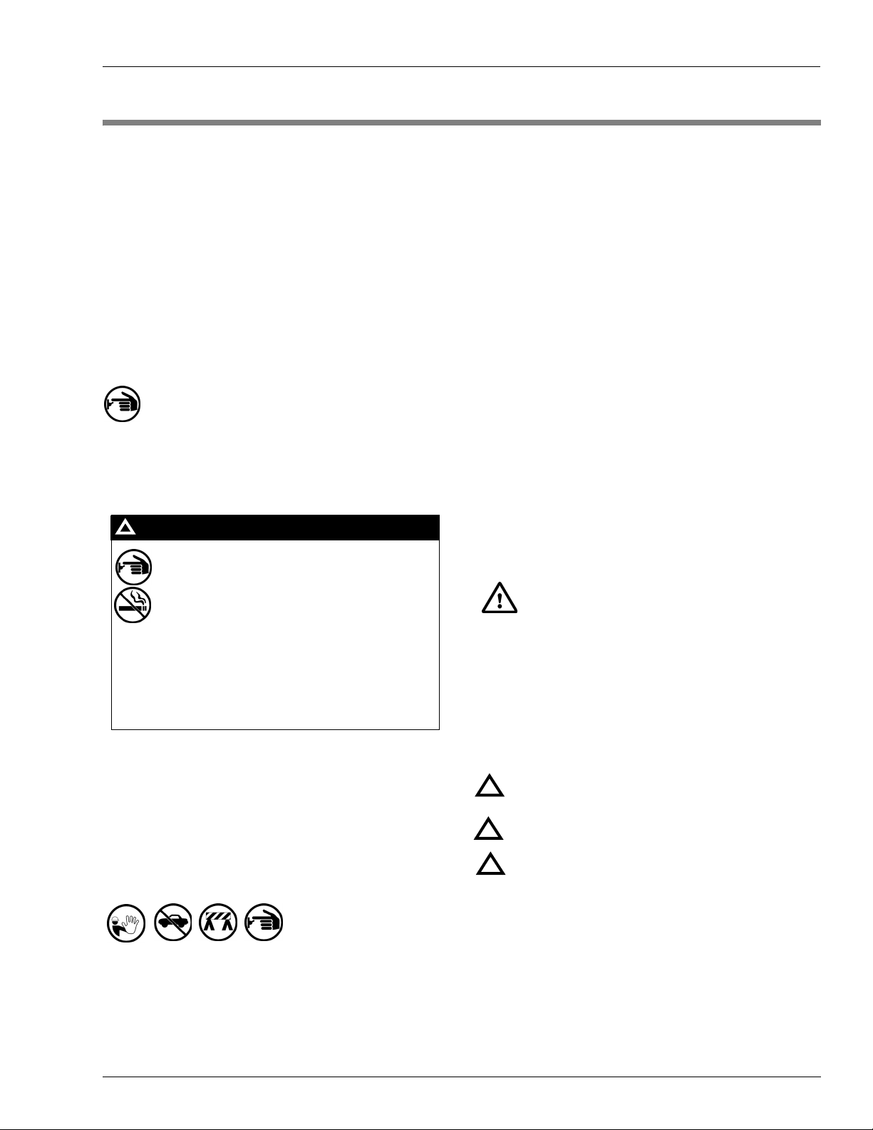
Safety Symbols and Warning Words
This section provides important information about warning
symbols and boxes.
Alert Symbol
This safety alert symbol is used in this manual and
on warning labels to alert you to a precaution which must be
followed to prevent potential personal safety hazards. Obey
safety directives that follow this symbol to avoid possible
injury or death.
Signal Words
These signal words used in this manual and on warning
labels tell you the seriousness of particular safety hazards.
The precautions that follow must be followed to prevent
death, injury or damage to the equipment
DANGER - This signal word is used to alert you to a
hazard to unsafe practice which will result in death or
!
serious injury
WARNING - This alerts you to a hazard or unsafe
practice that could result in death or serious injury.
!
CAUTION with Alert symbol - This signal word
designates a hazard or unsafe practice which may
!
result in minor injury.
CAUTION without Alert symbol - When used by itself,
CAUTION designates a hazard or unsafe practice
which may result in property or equipment damage.
- An evacuation of all unauthorized persons and vehicles
using safety tape, cones or barricades to the effected units
- A total electrical shut-off of that unit
MDE-4524A Vehicle Module Programming Manual· May 2006 Page 2-1
Working With Fuels and Electrical Energy
Prevent Explosions and Fires
Fuels and their vapors will become explosive if ignited.
Spilled or leaking fuels cause vapors. Even filling customer
tanks will cause explosive vapors in the vicinity of dispenser
or island.
Page 8
t
S
t
c
f
W
w
a
a
s
c
t
t
d
W
e
e
a
c
t
S
c
e
Important Safety Information
No Open Flames
Open flames from matches, lighters, welding
orches or other sources can ignite fuels and their vapors.
No Sparks - No Smoking
parks from starting vehicles, starting or using power tools,
burning cigarettes, cigars or pipes can also ignite fuels and
heir vapors. Static electricity, including an electrostatic
harge on your body, can cause a spark sufficient to ignite
uels and their vapors. After getting out of a vehicle, touch the
metal of your vehicle to discharge any electrostatic charge
before you approach the dispenser island.
orking Alone
It is highly recommended that someone who is capable of
rendering first aid be present during servicing. Be familiar
ith Cardiopulmonary Resuscitation (CPR) methods if you
re working with or around high voltages. This information is
vailable from the American Red Cross. Always advise the
tation personnel about where you will be working, and
aution them not to activate power while you are working on
he equipment. Use the OSHA tag out and lock out
procedures. If you are not familiar with this requirement, refer
o information in the service manual and OSHA
ocumentation.
orking With Electricity Safely
Be sure to use safe and established practices in working with
lectrical devices. Poorly wired devices may cause a fire,
xplosion or electrical shock. Be sure grounding connections
re properly made. Make sure that sealing devices and
ompounds are in place. Be sure not to pinch wires when
replacing covers Follow OSHA Lock-Out and Tag-Out
requirements. Station employees and service contractors
need to understand and comply with this program completely
o ensure safety while the equipment is down.
Emergency First Aid
Informing Emergency Personnel
Compile the following information for emergency personnel:
• Location of accident (for example, address, front/back of
building, and so on.)
• Nature of accident (for example, possible heart attack, run
over by car, burns, and so on.)
• Age of victim (for example, baby, teenager, middle-age,
elderly)
• Whether or not victim has received first aid (for example,
stopped bleeding by pressure, and so on.)
• Whether or not a victim has vomited (for example, if
swallowed or inhaled something, and so on.)
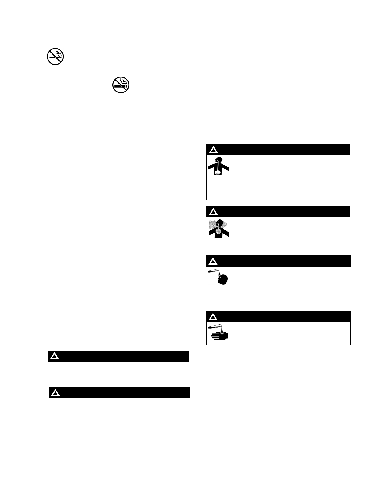
WARNING
!
Gasoline ingested may cause unconsciousness
and burns to internal organs.
Do not induce vomiting.
Keep airway open.
Oxygen may be needed at scene.
Seek medical advice immediately.
WARNING
!
Gasoline inhaled may cause unconsciousness
and burns to lips, mouth and lungs.
Keep airway open.
Seek medical advice immediately.
WARNING
!
Gasoline spilled in eyes may cause burns to eye
tissue.
Irrigate eyes with water for approximately 15
minutes.
Seek medical advice immediately
Hazardous Materials
ome materials present inside electronic enclosures may
present a health hazard if not handled correctly. Be sure to
lean hands after handling equipment. Do not place any
quipment in mouth.
WARNING
!
Gasoline spilled on skin may cause burns.
Wash area thoroughly with clear/water.
Seek medical advice immediately.
!
WARNING
This area contains a chemical known to the State of
California to cause cancer.
IMPORTANT: Oxygen may be needed at scene if gasoline
has been ingested or inhaled. Seek medical advice
immediately.
Lockout/Tagout
WARNING
!
This area contains a chemical known to the State of
California to cause birth defects or other reproductive
harm.
Lockout/Tagout covers servicing and maintenance of
Machines and equipment in which the unexpected
energization or start up of the machine(s) or equipment or
release of stored energy could cause injury to employees or
personnel. Lockout/Tagout applies to all mechanical,
hydraulic, chemical or other energy, but does not cover
electrical hazards. Reference Subpart S of 29 CFR Part 1910
IMPORTANT: Oxygen may be needed at scene if gasoline
has been ingested or inhaled. Seek medical advice
- Electrical Hazards, 29 CFR Part 1910.333 contains specific
Lockout/Tagout provision for electrical hazards.
immediately.
Page 2-2 MDE-4524A Vehicle Module Programming Manual· May 2006
Page 9

In an Emergency
The following actions are recommended regarding these hazards:
Important Safety Information
WARNING
!
Spilled fuels, accidents involving pumps/dispensers, or uncontrolled fuel flow creates
a serious hazard.
Fire or explosion may result causing serious injury or death.
Follow established emergency procedures.
Collision of Vehicle with Unit Fire at Island Fuel Spill
• Do not go near fuel spill or allow anyone else in the area.
• Use station EMERGENCY CUTOFF immediately. Turn off all system circuit breakers to
the island(s).
• Do not use console E-STOP, ALL STOP keys to shut off power. These keys do not remove
AC power and do not always stop product flow.
• Take precautions to avoid igniting fuel. Do not allow starting of vehicles in the area. No
open flames, smoking or power tools in the area.
• Do not expose yourself to hazardous conditions such as fire, spilled fuel or exposed
wiring.
• Call emergency numbers.
MDE-4524A Vehicle Module Programming Manual· May 2006 Page 2-3
Page 10

Important Safety Information
This page is intentionally left blank.
Page 2-4 MDE-4524A Vehicle Module Programming Manual· May 2006
Page 11
Vehicle Module Programmer Component Overview
3 – Component Overview
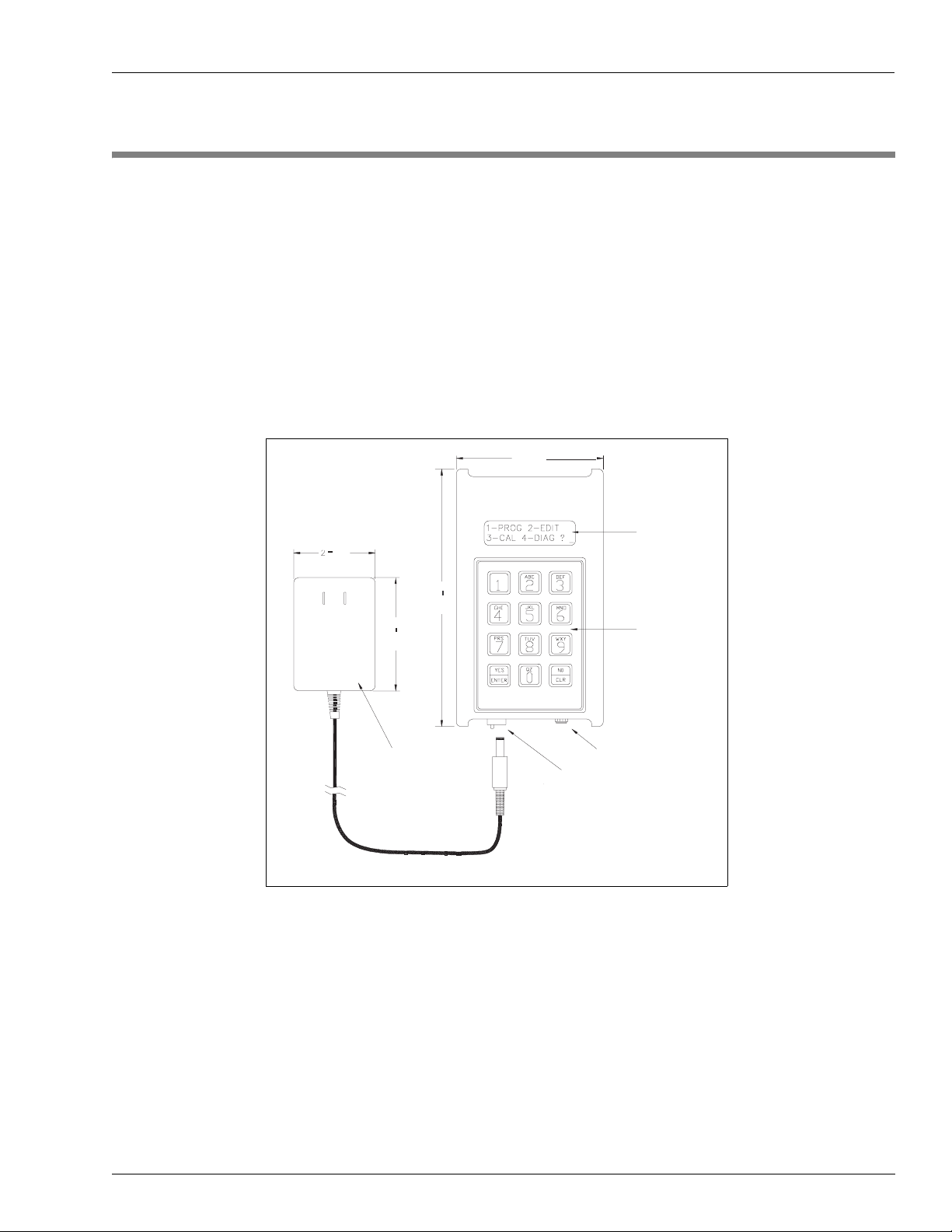
Vehicle Module Programmer
The Vehicle Module (VM) Programmer is a hand-held, cordless device used to interact with
the Fuel Point System components. It contains an antenna for communicating to the VM
through the vehicle T-Ring antenna. The two-line, alphanumeric display prompts the user
through each step, making it easy to use in the shop, in the fleet yard, at the job site, or at the
fueling island.
Figure 3-1
C06736 VM Programmer with Charger
3 9/16
(90.50)
1/4
2
(57.15)
(158.75)
6 1/4
2 3/4
(69.85)
CHARGER
CONNECTOR
CHARGER
32 CHARCTER
ALPHANUMERIC
DISPLAY
ALPHANUMERIC
KEYPAD
FACTORY PROGRAMMING
CONNECTOR
Note: C06736 VM Programmer will be shipped only till end of February 2006. Starting
March 2006, M06728A001 VM Programmer will be shipped.
The Programmer has five operating modes which are explained in detail in “Programmer
Operating Modes” on page 5-7.
• Program. When initially installing the VM, it allows you to load the vehicle's
identification and fuel control data, similar to encoding data for a card- or key-based Fuel
Management System (FMS). The VM can be re-programmed with new data at any time.
• Edit. This mode allows you to read back data to verify that a VM was programmed
correctly. It can also be used to change partial data in a programmed VM without reentering the entire VM data (as in Program mode).
MDE-4524A Vehicle Module Programming Manual· May 2006 Page 3-1
Page 12
Component Overview Vehicle Module Programmer
• Calibrate. The calibration feature is used initially to automatically calculate the odometer
ratio if it is not known. It is also used periodically to adjust for slight variations between
the odometer or hour meter and the VM.
• Diagnostic. Reads the entire VM and displays the results as a string of data.
• Ver si on . Reads and displays a VM's software revision date.
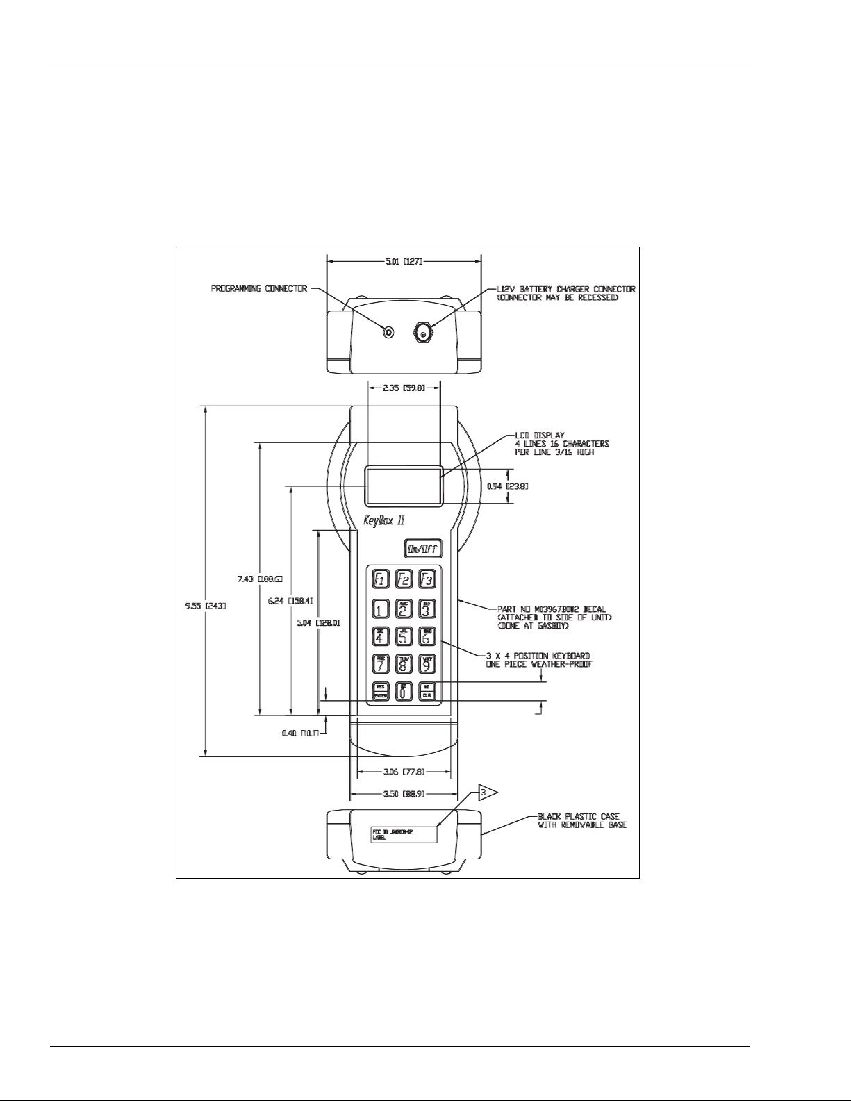
Figure 3-2 M06728A001 VM Programmer with Charger
View from top
Note: New programmer
does not use old
batteries (C09492).
View from below
Page 3-2 MDE-4524A Vehicle Module Programming Manual· May 2006
Page 13

Vehicle Module Programmer Component Overview
Charging the Programmer
Before using your Programmer for the first time, you must charge it overnight. After which the
Programmer and charger should always be plugged into a 115 VAC outlet when not in use to
keep the batteries charged.
Battery Pack Replacement
C06736 Replacement Batteries
In the event that the original batteries fail to hold a charge, Gasboy offers a replacement
battery pack (C09492).
Figure 3-3 C09492 Replacement Battery Pack
M06728A001 Replacement Batteries
The M06728A001 VM Programmer uses 5 commercially available AA Nickel Metal Hydride
(NiMH) batteries. Nickel Cadmium batteries (NiCd) may not be used in this programmer.
Note: The battery pack used in the Fuel Point Programmer may be damaging to the
environment if it is not disposed properly. Gasboy urges you to support your
community's recycling effort.
MDE-4524A Vehicle Module Programming Manual· May 2006 Page 3-3
Page 14

Component Overview Vehicle Module Programmer
This page is intentionally left blank.
Page 3-4 MDE-4524A Vehicle Module Programming Manual· May 2006
Page 15

Vehicle Module Field Descriptions Preparation for Programming
4 – Preparation for Programming
Vehicle Module Field Descriptions
The VM contains various data fields such as vehicle identification, allowable fuel type and
quantity, and miles or hours driven. It is important to understand these fields and their
interaction with the rest of the system. The Programmer is ordered from the factory to match
the base FMS, therefore, some of the fields described below might not be available with every
Programmer. Also, the VM does not use all of the fields that are encoded on a card or key, such
as the restriction digit, which serves no purpose with Fuel Point. Additionally, some of these
fields may be programmed into every VM at a site, but not prompted for during the
programming sequence, either for security reasons, or because the data is always the same.
Default prompts for commonly used fields are shown in parentheses after the field description.
System ID
The System ID is a unique number that identifies your system and safeguards against access
by users of other systems. Your unique System ID is assigned to the Programmer at the
factory; you will not be prompted for it during programming.
Vehicle Module Number (Enter VM Number)
The VM Number is used to identify the VM and is the lockout field used in the fuel
management system. The VM number length is fixed at 5 digits for FleetKey systems and
makes up the entire lockout field. For CFN systems, the VM Number can be up to 8 digits, and
can make up the entire lockout field for bit-mapped lockout, or can be combined with other
fields on the VM for limited lockout.
IMPORTANT INFORMATION
Every VM used at a site must have a unique VM Number because the Fuel Point Reader
uses the VM Number and System ID to monitor on-going transactions to tell if the
nozzle is still inserted into the same vehicle.
MDE-4524A Vehicle Module Programming Manual· May 2006 Page 4-1
Page 16

Preparation for Programming ID Fields
ID Fields
The ID Fields stored in the VM are used to identify the vehicle, driver, department, etc., and
are typically set to match the headings in the transaction printout. There are some differences
between the FleetKey and CFN systems as shown below.
FleetKey
The FleetKey system always has a 5-digit KEY1/VM field which is the main lockout field for
Key and VM transactions, and a 5-digit KEY2 field, which can be used as a secondary lockout
field for keys and not used with the VM. In addition, the FleetKey system can handle up to 8
additional ID Fields up to a maximum of 20 alphanumeric characters.
CFN
The CFN system allows up to 5 unique fields (maximum 19 digits) to make up what is
collectively referred to as the “account number.” When using bit-mapped lockout, the VM
field makes up the entire lockout field. When using limited lockout, the VM field is used for
part of the lockout and the other ID Fields in the account number make up the remainder of
the lockout field.
For CFN only, the VM can contain extra fields that would not be a part of the account field,
and thus not be used for lockout, but still may be stored in the transaction file. These fields can
be stored under the transaction's MANUAL field and, as long as the router fields are not used
for bank networking, they can be stored under the ROUTER field headings. One of the extra
fields can be alphanumeric, and will be stored as a ROUTER STRING in the transaction file.
Here is a list of currently available ID Fields and their corresponding three-digit type number.
The type number is used for programming the VM with the Reader Entry fields, as explained
later.
FIELD TYPE FIELD TYPE FIELD TYPE
Account 065 Driver 071 Security 081
Agency 099 Employee 072 Shift 082
Asset 090 Equipment 073 SKU 083
Badge 067 Fleet 074 Social Security 084
Bus 091 Job 066 Stock 085
Card 068 License 075 Tender Type * 095
Charge 079 Manifest 076 Track-II * 222
Clock 069 Manual 077 Trailer 104
Company 107 Participant ID 093 Truck 103
Department 070 Patron 078 Type 100
District 101 PIN 092 Unit 106
Division 089 Reefer 102 Vehicle 086
DIVLOC 088 Route 080 Work Order 087
* These fields require special handling and are explained below.
Page 4-2 MDE-4524A Vehicle Module Programming Manual· May 2006
Page 17

ID Fields Preparation for Programming
Tender Type
For CFN only, the 3-digit Tender Type field is used in conjunction with the Track-II field
explained below. If used, it must come before the Track-II field. If not used, the tender will
default to credit. Refer Point Of Sale and Shift Change Manual C35923.
Track-II
For CFN only, the Track-II field is used to program a VM to match a bank card or some other
non-club card format. When it is used, you typically would not have any of the other ID fields
on the VM. When matching data from an existing card, a field separator character (-) must be
represented as a D on the Programmer.
Reader Entry Fields (RDR FLD 1,2, or 3)
For CFN only, these fields are used to gather identification data from an island or dispenser
card reader, and merge that information with the data stored on the VM. For example, if
multiple drivers share a vehicle, you may want to encode only vehicle data on the VM, and
have employee and department identification entered via keypad or magnetic stripe card. Up
to 3 entries can be required for each VM transaction. These entries can be used as part of the
lockout field.
Each Reader Entry Field is made up of 1 mandatory part, and up to 3 optional parts. When
the Programmer prompts for a Reader Entry Field, you will see 3, 4, 6, or 7 to 26 question
marks, depending on the number of mandatory and optional parts required. Note that for
optional part 2 to be used, optional part 1 must also be present, and for optional part 3 to be
used, optional parts 1 and 2 must be present.
PART LENGTH DESCRIPTION
mandatory 3 ID Field to be
gathered from card
reader; from list
optional 1 1 How data is
gathered; keypad or
magnetic card
optional 2 2 Maximum number
optional 3 1-20 Card reader prompt
of digits to be
gathered; 1 to 19
while gathering data
Mandatory Part
The first 3 question marks prompt for the mandatory part. This is the 3-digit ID Field type for
the data that will be gathered from the card reader.
Optional Part 1
The fourth question mark prompts for the first optional part. If this part is not included (only
three question marks shown), the data field will be entered from the card reader's keypad, the
maximum number of digits gathered from the card reader will be whatever the card reader will
allow (for example, the Gasboy ICR will allow 16 digits), the digits will be shown on the
reader display as entered, and the card reader entry prompt will be the default prompt loaded in
the SCII FUELPT Global Parameters.
MDE-4524A Vehicle Module Programming Manual· May 2006 Page 4-3
Page 18

Preparation for Programming Expiration Date (Enter EXPIRE)
If this part is present, there are 3 possible values:
0 = data will be entered through card reader keypad and the entered data will be shown on the
reader display
1 = data will be entered through the card reader keypad and the data will be shown as asterisks
(*) on the reader display for security purposes
2 = the data will be entered through the card reader via a special Fuel Point card
Optional Part 2
Question marks 5 and 6 prompt for the second optional part. If this part is not included (only 5
question marks shown), the maximum number of digits gathered from the card reader will be
whatever the card reader will allow (for example, the Gasboy ICR will allow 16 digits), and
the card reader entry prompt will be the default prompt loaded in the SCII FUELPT Global
Parameters.
If this part is present, there are 3 possible values:
0 = maximum number of digits gathered will be whatever the card reader will allow
1-16 = maximum number of digits gathered via keypad entry
1-19 = maximum number of digits gathered via a special Reader Entry data card
Optional Part 3
Question marks 7 through 26 prompt for the message to display at the card reader when
prompting for the Reader Entry data. If this part is not present, the prompt at the card reader
will be the default prompt loaded in the SCII FUELPT Global Parameters. If this part is
present, it allows you to enter a card reader prompt unique to each VM. For example, you may
want to have all of the pooled-cars prompt ENTER EMPLOYEE and all of the off-road
vehicles prompt ENTER JOB.
Expiration Date (Enter EXPIRE)
The Expiration Date is assigned to establish a lifetime for the VM. FleetKey uses 4 digits
(YYMM) and CFN systems may use either 4 digits (YYMM) or 2 digits (YY). If programmed
with all zeros in the field, expiration is ignored.
Page 4-4 MDE-4524A Vehicle Module Programming Manual· May 2006
Page 19

Product Limit (Enter LIMIT) Preparation for Programming
Product Limit (Enter LIMIT)
The Product Limit code is used to restrict the maximum quantity of fuel dispensed per
transaction. It is provided as a safeguard to prevent accidental spillage. FleetKey can handle
up to 10 limit codes (0-9), and CFN systems can handle up to 100 (default is 20). The limit
codes do not have to be numbered sequentially. In both systems, not having the limit code on
the VM is the same as if it was on with code 0.
The limit code programmed in the VM is not an actual quantity amount. When your
Authorized Service Representative (ASR) configures your FMS, a table is set up to your
specifications. The table contains limit codes and quantity values assigned to those limit
codes. Limit codes are linked with a type of vehicle and are assigned a quantity just slightly
greater than the vehicle's fuel tank capacity.
Complete Table 4-1, Product Limit Codes, prior to programming the VM. Make sure the
completed table is available at start-up, so it can be loaded into the system at that time.
Photocopy this sheet if you need more space.
Table 4-1: Product Limit Codes
Limit Code Quantity
Product Authorization (Enter AUTH)
This code authorizes the fuel types the vehicle is allowed to access. An authorization code
allows one or more fuel types, also represented as codes. FleetKey can handle up to 9 (1-9)
authorization codes and each code allows up to 5 fuel types. CFN systems can handle up to
100 authorization codes and each code allows up to 100 fuel types (default is 40). In FleetKey,
authorization code 0 always allows all fuel types. In CFN systems, if no fuel types are loaded
for authorization code 0, it will allow all fuel types, otherwise, code 0 will allow the fuel types
loaded. In both systems, not having the authorization code on the VM is the same as if it was
on with code 0.
First, assign a 2-digit fuel code to each of your fuel types, using Table 4-2. Then, assign the
fuel codes to the authorization codes as you require, using Table 4-3. Make sure this
information is available to load into the FMS at start-up. Photocopy these sheets if you need
more space.
MDE-4524A Vehicle Module Programming Manual· May 2006 Page 4-5
Page 20

Preparation for Programming Price Level (Enter PRICE)
Table 4-2: Fuel Code Assignments
Fuel Code Description
Table 4-3: Authorization Assignments
Product Codes
Auth. Code
Allowed
Price Level (Enter PRICE)
Price Level is used only with CFN systems. It enables you to have different prices for each
fuel type. In the system, you have price codes and price levels. One price code is assigned to
each pump hose. Each price code can have multiple price levels. By programming different
price levels into different AM’s, it is possible to charge different prices to different customers
at the same pump. If the VM does not have a price level, the system uses level 2.
For example, suppose pump 1 is assigned price code 1, and price code 1 allows 3 price levels.
The 3 price levels are set as:
level 0 = $1.259
level 1 = $1.219
level 2 = $1.179
One customer may have a VM programmed with price level 1 and another may have price
level 2. The first customer would get charged $1.219, while the second customer gets charged
$1.179 at the same pump.
Page 4-6 MDE-4524A Vehicle Module Programming Manual· May 2006
Page 21

Odometer Or Hours Selection (SEL ODOMETER - 0, HOURS - 1) Preparation for Programming
Make sure the price codes and price levels are loaded during the FMS start-up. Use Table 4-4,
to lay out your price codes and levels. Photocopy this sheet if you need more space.
Table 4-4: Price Code Assignments
Price Level 1 Level 2 Level 3 Level 4 Level 5
Odometer Or Hours Selection (SEL ODOMETER - 0, HOURS - 1)
The odometer or hours data is stored in a counter field. A single VM has 1 counter field, while
a dual VM has 2. The Programmer's Odometer or Hours Selection input prompt determines
whether the counter field following the selection, is used for odometer or for hours. Enter 0 if
the VM is to record odometer or 1 if it is to record engine hours. For a dual VM, the selection
prompt occurs twice, once for each counter.
Each counter field has an associated ratio field, described in detail later in this section, that
contains the number of pulses in a mile (odometer), or the number of time intervals in an hour
(hour meter). The maximum value of the counter field 1 ratio is 640000, and the maximum
counter field 2 ratio is 64000. Since some vehicle's odometer ratios may be higher than 64,000
pulses per mile, counter 1 should be used for odometer and counter 2 used for hours, in a dual
VM. Since a single VM uses only counter field 1, it can be programmed for either odometer or
hours, without worry of ratio limitations.
Odometer or Hours Entry (Enter ODOMETER)
This field allows you to enter decimal number up to 1 decimal place (maximum of 7 digits
before decimal). For odometer, enter the dashboard odometer reading. For hours, enter the
reading from the hour meter.
MDE-4524A Vehicle Module Programming Manual· May 2006 Page 4-7
Page 22

Preparation for Programming Odometer Ratio (Enter ODO RATIO)
Odometer Ratio (Enter ODO RATIO)
The VM receives odometer data as a series of pulses. These pulses may come from sensors
mounted to the transmission, transaxle, or drive shaft, or from circuits in the vehicle's
computer module or cruise control.
IMPORTANT INFORMATION
The vehicle's ABS system must not be used as a source for odometer pulses.
Any Fuel Point Vehicle Modules currently installed must be immediately
disconnected from the ABS system.
With electronic speed transducers, the connection should be made at one of
these locations: at the buffered output side of any vehicle's control modules,
such as the powertrain control module (PCM); or, if buffered output is not
available, at the transmission's speed generator signal wire.
The number of pulses-per-mile is affected by several factors, such as, tire size, axle ratio, and
transmission specifications. Due to all these variances, the VM requires you to program in a
ratio of the number of pulses it is expected to receive per mile. This section helps you to
determine the proper ratio for your particular vehicle. If you do not know the vehicle specs, the
VM Programmer has a calibration feature to help narrow down the correct odometer ratio.
Keep in mind that the ratio for the first counter field has a maximum limit of 640000 and the
maximum ratio for the second counter (for a dual VM) is 64000. For this reason, the first
counter field should be odometer and the second should be hours, when using a dual VM.
Mechanical Odometer Cable
Older vehicles use a mechanical cable to deliver odometer pulses to the dashboard. To allow
the VM to record these pulses, a mechanical transducer should have been purchased and
installed according to the guidelines and restrictions outlined in C35699 Fuel Point Vehicle
Module Installation Manual. The formula for figuring the mechanical odometer ratio is:
Cable revs/mile X sensor pulses/rev
Cable revs per mile is the number of revolutions the mechanical cable turns for each mile.
This number can be found in the transmission specification. Typically it is:
Domestic - 1000 revs/mile
Foreign - 900 revs/mile
Sensor pulses per rev is the number of electronic pulses generated for each revolution of the
sensor input. This is determined by the sensor manufacturer and may be stamped on the
sensor. A common value is 8 pulses/rev.
Page 4-8 MDE-4524A Vehicle Module Programming Manual· May 2006
Page 23

Odometer Ratio (Enter ODO RATIO) Preparation for Programming
Therefore, the typical odometer ratio for a domestic vehicle is 8000 pulses/mile and for a
foreign vehicle it is 7200 pulses/mile. Use these values for the VM odometer ratio if you are
not sure of the exact values.
Electronic Odometer
On new vehicles, the odometer signal to the VM is tapped off an existing sensor or
speedometer signal from an electronic circuit. Several ways to figure the electronic odometer
ratio are shown below:
• Match working vehicle. If a previously equipped vehicle has accurate odometer data in
the VM, use the same ratio for all other vehicles in the fleet with the same specs.
• Use published ratio. If the VM odometer input is a conditioned signal coming from the
vehicle's computer module or cruise control, the manufacturer's wiring diagram may show
the number of pulses per mile it is generating. These values are typically round numbers
such as 10,000, 20,000, or 40,000.
Figure 4-1
Sample Wiring Diagram. Notice Pulses Per Mile.
IGNITION
VEHICLE
SPEED
INPUT
4000 PULSES
PER MILE
INSTRUMENT
CLUSTER
ELECTRONIC CONTROL MODULE
VEHICLE
SPEED
INPUT
(ECM)
2000 PULSES
PER MILE
VEHICLE
SPEED
SENSOR
PERMANENT
MAGNET
GENERATOR
4000 PULSES
PER MILE
VEHICLE
SPEED
INPUT
CRUISE
CONTROL
MODULE
• Use engine computer ratio. Today’s over-the-road trucks have smart engines allowing
you to view and adjust many performance parameters through the diagnostic port. If the
VM odometer signal is tapped off from the same signal source as the dashboard
speedometer, you can use the speedometer ratio stored in the engine computer for the VM
odometer ratio.
• Calculate from vehicle specs. If the VM odometer receives input directly from the
speedometer sensor mounted in the transmission, you may be able to calculate the correct
ratio using specs from the vehicle manufacturer.
MDE-4524A Vehicle Module Programming Manual· May 2006 Page 4-9
Page 24

Preparation for Programming Odometer Ratio (Enter ODO RATIO)
Figure 4-2
SENSOR
OUTPUT
VOLTAGE
Sample Speedometer Circuit
SPEEDOMETER
SENSOR
TRANSMISSION
MAGNETIC
FIELD
SPEEDOMETER
Although there are variations among manufacturers and vehicle types, a typical speedometer
system on a rear-drive-axle vehicle is described here. A gear, usually called the speedometer
signal gear, is mounted to the output shaft of the transmission. The speedometer sensor is
mounted to the transmission so that its tip is in close proximity to the signal gear's teeth. A
permanent magnet located in the speedometer sensor establishes a magnetic field at the tip.
The magnetic field is repeatedly cut by the teeth on the signal gear, creating alternating current
voltage impulses that are transmitted to the speedometer. The frequency and amplitude of the
signal is directly proportional to the speed of the signal gear. The speed of the signal gear is
determined by the rotation of the drive shaft, which is determined by the drive axle ratio and
tire size. Therefore, the number of pulses-per-mile from the speedometer sensor is calculated
from the formula:
# teeth on signal gear X tire revs/mile X drive axle ratio
# of teeth on signal gear is found in the transmission specifications. A typical number of teeth
is 16.
Tire revs per mile can be found in the tire manufacturer's spec sheet. These figures are
standard throughout the tire industry. For example, a new 12.00 R 20 tubeless tire turns 470
revolutions per mile.
Page 4-10 MDE-4524A Vehicle Module Programming Manual· May 2006
Page 25

Odometer Ratio (Enter ODO RATIO) Preparation for Programming
Figure 4-3
Sample Truck Tire Size Chart
TUBE TIRES TUBELESS TIRES
Tire Size Revs
Per Mile
Tire Size
Revs
Per Mile
Drive axle ratio can be found in the manufacturer's line setting ticket, and also on a tag
attached to the differential assembly on rear wheel drive vehicles.
Figure 4-4 Sample Line Setting Ticket
Drive axle
ratio
MDE-4524A Vehicle Module Programming Manual· May 2006 Page 4-11
Page 26

Preparation for Programming Hours Ratio (Enter ODO Ratio)
Figure 4-5 Sample Rear Differential Showing Axle Ratio Marking
SN 622451A
16645837C95 502CA200--4Z
Example:
Signal gear teeth = 16
Tire size = 10.00 R 20 = 502 revs/mile
Axle ratio = 3.41:1
Ratio = 16 x 502 x 3.41
= 27,389 (drop the decimal places)
• Use programmer's calibration feature. If you cannot figure the odometer ratio using any
method listed above, just enter any number and let the VM Programmer's calibration
feature narrow down the correct ratio. This method may require several calibrations to get
a good ratio, and the vehicle may have to travel several hundred miles between the
calibrations. Start with a number between 10,000 and 100,000.
RATIO 4.78
Hours Ratio (Enter ODO Ratio)
The VM counts time in increments of approximately 128ms, therefore the hours ratio is fixed
at 28,000 pulses-per-hour. Regardless of what is entered for this ratio, the VM automatically
changes it to 28,000. You should just press the ENTER key for the ratio prompt of an hours
counter.
Dual Counters (DUAL COUNTERS, NO - 0, YES - 1)
This field determines if the Programmer prompts for a second counter (odometer or hours)
field. Enter 0 for a single VM or 1 for a dual VM.
Page 4-12 MDE-4524A Vehicle Module Programming Manual· May 2006
Page 27

Vehicle Module Program Data Sheet Preparation for Programming
Vehicle Module Program Data Sheet
As you can see, there are many fields that may be programmed into a VM. It is helpful to write
all of the data to be programmed into a chart that you can take out to the vehicle. Here is a
sample of a chart with the data filled in. On the next page is a blank chart, you can tailor to
your system.
VM
NUMBER
1374 288 AJY6755 8 1 ODOM 8000 HRS N/A
1375 1644 TAM 0 6 93 6 2 ODOM 26000 HRS N/A
1376 108 TL1999 3 4 ODOM 40000 HRS N/A
1377 5766 SRL5320 3 4 ODOM 40000 N/A N/A
VEHICLE
NUMBER
LICENSE
PLATE
LIMIT
CODE
AUTH
CODE
COUNTER
1 TYPE
COUNTER
1 RATIO
COUNTER
2 TYPE
COUNTER
2 RATIO
MDE-4524A Vehicle Module Programming Manual· May 2006 Page 4-13
Page 28

Preparation for Programming Vehicle Module Program Data Sheet
VM
NUMBER
VEHICLE
NUMBER
LICENSE
PLATE
LIMIT
CODE
AUTH
CODE
COUNTER
1 TYPE
COUNTER
1 RATIO
COUNTER
2 TYPE
COUNTER
2 RATIO
Page 4-14 MDE-4524A Vehicle Module Programming Manual· May 2006
Page 29

Ground Loop Communications Operation
5 – Operation
Ground Loop Communications
If the vehicle has been wired for ground loop fueling, the T-Ring is connected to the VM's
Gate connectors. The Programmer modes: Program, Edit, Calibrate, and Version will not work
via the VM's Gate connectors. The Programmer can access those modes only through the
VM's T-Ring connectors. There are two ways to accomplish this:
• Use a spare T-Ring with a long cable attached. The cable connects to the T-Ring
connectors on the VM. There is no need to disconnect the VM’s Gate ring. The
Programmer can now use any mode to access the VM via the temporary T-Ring. When
finished, disconnect the T-Ring so that it can be used to check other vehicles.
• At the VM, move the ring wires from the Gate connectors to the T-Ring connectors. Any
Programmer mode can be accessed via the vehicle's gate ring mounted to the underside of
the vehicle. When finished using the Programmer, move the ring wires back to the Gate
ring connectors on the VM.
Note: The Programmer's Diagnostic mode can be accessed from a ring at either the Gate or
T-Ring connectors.
General Programmer Operation
This section describes the standard operating style of the VM Programmer common to all
operating modes. In the text, YES and ENTER refer to the key labeled YES/ENTER; NO
and CLR refer to the key labeled NO/CLR.
Turning On Programmer
Turning Off Programmer
To turn the Programmer on, press and hold the Enter key (in C06736 VM Programmer with
Charger) or On/Off key (in M06728A001 VM Programmer with Charger) until the main
menu appears.
On/Off
Press the CLR and 3 keys simultaneously (in C06736 VM Programmer with Charger) or
On/Off key (in M06728A001 VM Programmer with Charger) to turn the Programmer off. To
conserve battery power, the Programmer also shuts itself off when it has completed
programming or calibrating a VM, or when there is no keypad activity for 100 seconds.
MDE-4524A Vehicle Module Programming Manual· May 2006 Page 5-1
Page 30

Operation General Programmer Operation
Mode Selection
After the Programmer is turned on, the first menu, showing modes 1 through 4 is displayed.
Within 4 seconds, the second menu, showing mode 5, is displayed. The Programmer toggles
between menus every 4 seconds, or you can manually switch menus by pressing ENTER. To
select a mode, press the mode number followed by ENTER. Selection can be made for any
mode even when the display is not currently showing its associated menu
_
_
DIAG ?
?
1
YES
ENTER
_
1 PROG 2 EDIT
_
3 CAL 4
5 -- VERS
ENTER VM NUMBER:
522748_
Accepting Old Data and Clearing the Display for New Data Entry
The Programmer saves previously entered data for the Program and Edit modes. When
stepping through these modes, that data is displayed for each field so that you can just press
ENTER to keep the data as-is and advance to the next field. If you need to change any data
within a field, you must press the CLR key first, to clear the field for new data entry. Then
press the ENTER key to save the change. In order to avoid repetition throughout this manual,
most subsequent example sequences starts with the field already cleared.
Note: If you make any mistake while typing the data, you can press the CLR key to go back to
the beginning of the current field, then type the correct data.
ENTER VM NUMBER:
5001
YES
ENTER
NO
CLR
ENTER DIVISION:
006442
ENTER LICENSE:
TAM0693
ENTER LICENSE:
???????_
Page 5-2 MDE-4524A Vehicle Module Programming Manual· May 2006
Page 31

General Programmer Operation Operation
Entering Numeric Data
On the keypad, press the number that you want to enter into the field. If there are multiple
digits within a field, the cursor automatically advances to the next position. After all digits
have been entered, press ENTER to advance to the next field. If you press ENTER before all
data has been entered, it will fill the un-entered most significant digits with zeros, then
advance to the next field. For example, to enter the number 16 into a 4-digit field, type 1, 6,
ENTER. The data will be stored as 0016.
ENTER VEHICLE:
1
1?
??
MNO
6
YES
ENTER
ENTER VEHICLE:
16?
ENTER LIMIT:
5_
Entering Alphanumeric Data
On the keypad, the keys 2 through 0 have letters above the numbers. While entering data into
an alphanumeric field, the first time you press a number, it shows that number, but the cursor
does not advance to the next position. The second time you press the same number, it shows
the first letter marked above the number. Pressing it again shows the second letter, and
pressing it a fourth time shows the third letter. An alphanumeric field can have any
combination of letters and numbers. In an alphanumeric field, you must press the ENTER key
to advance the cursor. After all characters have been entered, press ENTER to advance to the
next field. If you press ENTER before all data has been entered, it will fill the un-entered most
significant characters with zeros, then advance to the next field. For example, to enter the
string A37R into a six character field, type:
2, 2, ENTER, 3, ENTER, 7, ENTER, 7, 7, 7, ENTER, ENTER.
?
The data is stored as 00A37R.
MDE-4524A Vehicle Module Programming Manual· May 2006 Page 5-3
Page 32

Operation General Programmer Operation
Alphanumeric fields are not standard and must be specified while ordering the Fuel Point and
Fuel Management System from the factory.
ABC
ABC
YES
ENTER
DEF
3
YES
ENTER
PRS
7
YES
ENTER
PRS
7
PRS
7
ENTER VEHICLE:
2
ENTER VEHICLE:
2
ENTER VEHICLE:
ENTER VEHICLE:
ENTER VEHICLE:
ENTER VEHICLE:
ENTER VEHICLE:
ENTER VEHICLE:
ENTER VEHICLE:
2?????
?????
A
A?
????
????
A3
???
A3?
A37
???
A37?
A377
A37P
??
??
??
PRS
7
YES
ENTER
YES
ENTER
ENTER VEHICLE:
??
A37R
ENTER VEHICLE:
A37R?
ENTER LIMIT:
?
5_
Page 5-4 MDE-4524A Vehicle Module Programming Manual· May 2006
Page 33

General Programmer Operation Operation
Entering Spaces and Special Characters
If the VM is set up to store the reader prompt for the Reader Entry Fields, you will probably
need to enter spaces and other characters for the message. On the Programmer, the 1 key
scrolls through a list of available characters. When entering data into an alphanumeric field,
the first time you press the 1 key, it shows as 1. After that, the 1 key shows a different
character each time it is pressed, until it gets back to 1. Press ENTER to select one of the
special characters as it is displayed. The special characters available are:
SPACE
# number sign
?question mark
^ caret
. period/decimal point
- hyphen
,comma
ENTER RDR FLD 1:
066008ENTER?
ENTER RDR FLD 1:
1
066008ENTER1
ENTER RDR FLD 1:
1
066008ENTER
ENTER RDR FLD 1:
1
066008ENTER#
ENTER RDR FLD 1:
1
066008ENTER?
ENTER RDR FLD 1:
1
066008ENTER^
ENTER RDR FLD 1:
1
066008ENTER.
ENTER RDR FLD 1:
1
066008ENTER-????
????
????
????
????
????
????
????
ENTER RDR FLD 1:
1
066008ENTER,
ENTER RDR FLD 1:
1
066008ENTER_????
ENTER RDR FLD 1:
YES
ENTER
066008ENTER ?
MDE-4524A Vehicle Module Programming Manual· May 2006 Page 5-5
????
???
Page 34

Operation General Programmer Operation
Entering Odometer or Hours Data
The odometer and hours fields (generically referred to as the counter fields), allow entry of 7
whole digits plus tenths.
DEF
3
ENTER ODOM [1]
???????.3
PRS
ENTER ODOM [1]
7
MNO
6
ENTER ODOM [1]
TUV
ENTER ODOM [1]
8
GHI
ENTER ODOM [1]
4
MNO
ENTER ODOM [1]
6
YES
ENTER
ENTER ODO RATIO
Editing Within a Field
To edit data within a field, press the CLR key to set the cursor back one space. It has now
erased the data previously entered in that position. Each subsequent press of the CLR key sets
the cursor back another space. Once you get to the position you want, start entering the correct
data.
??????3.7
?????37.6
????376.8
???3768.4
??37684.6
?
?????
ABC
2
MNO
6
TUV
8
NO
CLR
NO
CLR
JKL
5
Page 5-6 MDE-4524A Vehicle Module Programming Manual· May 2006
ENTER ODO RATIO
2?????
ENTER ODO RATIO
26????
ENTER ODO RATIO
26B???
ENTER ODO RATIO
26????
ENTER ODO RATIO
2?????
ENTER ODO RATIO
25????
Page 35

Programmer Operating Modes Operation
Programmer Operating Modes
Program Mode
When the VM is initially installed, the Program Mode allows you to load the vehicle's
identification and fuel control data, similar to encoding data for a card- or key-based FMS.
Since the programmer is set up at the factory, it prompts for the fields, needed for the VM to
work at each specific site. An explanation of the fields that may be used is given in the
previous section. The VM can be re-programmed with new data at any time.
Here is a typical programming session incorporating all of the items previously discussed.
Your Programmer may be set up differently than the examples. Just key in the data for your
particular situation as prompted on the Programmer display. Remember, if at any time you
make a mistake typing the data, you can press the CLR key to go back to the beginning of the
current field, then type the correct data.
1 Take the completed VM Program Data sheet out to the vehicle.
2 Turn on the Programmer. Refer to “Turning On Programmer” on page 5-1.
3 Select Program mode.
1
4 Enter the VM number.
1
5 Enter the Vehicle number.
ABC
2
YES
ENTER
DEF
3
TUV
8
1 - PROG 2 - EDIT
3 - CAL 4 - DIAG ?
PRS
7
TUV
8
GHI
4
YES
ENTER
YES
ENTER
ENTER VEHICLE:
ENTER VM NUMBER:
288???
1374?
MDE-4524A Vehicle Module Programming Manual· May 2006 Page 5-7
Page 36

Operation Programmer Operating Modes
6 Enter the License number.
Note: Since this is an alphanumeric field, you must press ENTER to advance to the next
character position.
7 Enter the Limit code.
TUV
8
8 Enter the Authorization code.
1
9 Odometer is the first field counter that appears.
QZ
0
10 When programming a newly installed VM, it is a good idea to test the installation. Press
YES
ENTER
YES
ENTER
YES
ENTER
ENTER LIMIT:
8
ENTER AUTH.
1
SEL ODOMETER - 0
0_ HOURS - 1
ENTER at the following prompt to set the odometer at 0000000.0. The correct initial reading
of the odometer is loaded after testing the odometer connection.
YES
ENTER
Page 5-8 MDE-4524A Vehicle Module Programming Manual· May 2006
ENTER ODOM [1]
???????.?
Page 37

Programmer Operating Modes Operation
11 Enter 1 as the ratio. This allows a quick way to test if the VM is recording pulses, without
having to drive very far.
1
12 This is a dual VM.
1
13 The second field is hours.
1
14 Since you want to test the installation, enter an engine hours reading that ends in 0.9 (0.9 hours
YES
ENTER
YES
ENTER
YES
ENTER
ENTER ODO RATIO:
1????
DUAL COUNTERS 1
NO - 0 YES - 1
SEL: ODOMETER - 0
SCND 1
HOURS - 1
equals 54 minutes). That way, you only have to wait 6 minutes to verify that the engine hours
connection is functioning. The correct starting hours reading will be loaded after testing.
1
15 Hold the Programmer near the vehicle's T-Ring. If the vehicle is equipped with two T-Rings,
ABC
2
DEF
3
WXY
9
YES
ENTER
PRESET TIME [2]
[H] ????123.9
perform the programming at one ring, then use the second ring while Testing the Programmed
VM steps. This allows testing of both ring circuits.
HOLD PROGRAMMER
NEAR TANK RING
IMPORTANT INFORMATION
IMPORTANT INFORMATION
The Programmer cannot program a VM for engine hours when the vehicle is
running. Ensure the vehicle is shut off during Programming.
MDE-4524A Vehicle Module Programming Manual· May 2006 Page 5-9
Page 38

Operation Programmer Operating Modes
16 When communications is established, a series of beeps will be heard. Continue to hold the
Programmer near the T-Ring. Programming takes about 15 seconds.
TRANSMITTING
PLEASE WAIT
17 When programming is complete, you will hear a long beep.
TRANSMISSION
COMPLETE
18 The Programmer turns off automatically
Testing the Odometer/Hours Operation
1 Since the odometer ratio was programmed as 1, you only need to back the car up about 10 feet,
then forward again, to make the VM think you drove many miles. Since this particular vehicle
is also recording engine hours, you need to let it idle for at least 6 minutes to get the VM to
increment to the next hour.
!
DANGER
To avoid the build-up of deadly carbon-monoxide gas, DO NOT idle the vehicle in an
enclosed area.
2 Turn on the Programmer. Refer to “Turning On Programmer” on page 5-1.
3 Select Calibrate mode. We are only using Calibrate mode here because we know the odometer
data is incorrect. The sequence presented here does not use Calibrate mode features for
determining the correct ratio and resetting the initial counters. These features are explained
later in the Calibrate Mode section.
DEF
3
YES
ENTER
1 - PROG 2 - EDIT
3 - CAL 4 - DIAG ?
Page 5-10 MDE-4524A Vehicle Module Programming Manual· May 2006
Page 39

Programmer Operating Modes Operation
4 Hold the Programmer near the vehicle's T-Ring. If the vehicle is equipped with two T-Rings,
use a different ring than used earlier, in order to check both rings.
HOLD PROGRAMMER
NEAR TANK RING
IMPORTANT INFORMATION
The Programmer cannot calibrate a VM with engine hours when the vehicle is
running. Ensure the vehicle is shut off during Calibrate mode.
5 When communication is established, a series of beeps will be heard. Continue to hold the
Programmer near the T-Ring. It takes about 5 seconds to read the data.
TRANSMITTING
PLEASE WAIT
6 As we want to check both counters, select 2.
ABC
2
7 The display now shows the counter 1 odometer data. The number on the top line represents the
YES
ENTER
SEL CALIB: 1ST - 0
2ND - 1 BOTH - 2 ?
initial programmed whole odometer. The bottom left shows the ratio, and the bottom right
shows the current VM odometer. If the current VM odometer is greater than the initial
odometer, you have verified that the odometer circuit is functioning properly. Now you can
program in the correct starting odometer.
YES
ENTER
LAST[1]? 0000000
000001.0 0000124
Note: If the current VM odometer does not change, check the VM installation.
8 Enter the dashboard odometer reading.
ABC
2
GHI
1
4
MDE-4524A Vehicle Module Programming Manual· May 2006 Page 5-11
MNO
6
PRS
7
TUV
8
YES
ENTER
ENTER ODOM [1]
??26841.7
Page 40

Operation Programmer Operating Modes
9 Press 1, since we want to change the ratio as well as the odometer.
1
10 The calculated ratio shown is incorrect because the initial data loaded was just test data. Press
YES
ENTER
MILEAGE ONLY - 0
COUNT RATIO -1 1
NO, since you do not want to accept the calculated ratio.
NO
CLR
11 Enter the correct odometer ratio, if known. If you do not know the correct ratio, enter a number
RAT 000001.0 OLD
? 000000.2 NEW
between 8000 and 100000.
8
00
0
YES
ENTER
ENTER ODOMETER
RATIO 8000??
Note: Keep in mind that this ratio is an estimate and may be incorrect. When this testing
procedure is complete, take a short (3-4 mile) test drive. This should provide enough
data to provide a closer ratio. Then redo the testing procedure using the new number.
Enter YES to accept the calculation ratio at Step 10.
12 The top line shows the newly entered odometer and ratio. Press ENTER if these are correct.
YES
ENTER
13 The display now shows the counter 2 hours data. Similar to counter 1 above, the top line
ODOMETER 0026841
RATIO 008000 ?
displays the initial hour entry, and the bottom line shows the ratio on the left (always 28000 for
hours), and the current hours on the right. If the current VM hours is greater than the initial
hours, you have verified that the engine hours circuit is functioning properly. Now you can
program in the correct starting engine hours.
YES
ENTER
LAST[2]? 0000000
28000.0 0000124
Note: If the VM hours does not change, check the VM installation.
Page 5-12 MDE-4524A Vehicle Module Programming Manual· May 2006
Page 41

Programmer Operating Modes Operation
14 Enter the hour meter reading, including tenths if present. Remember to enter leading zeros as
necessary. If there is no hour meter, just press 0, then ENTER to start the hours counter at
zero.
GHI
4
0
15 Hold the Programmer near the vehicle's T-Ring.
HOLD PROGRAMMER
NEAR TANK RING
16 When communications is established, a series of beeps will be heard. Continue to hold the
JKL
5
0
MNO
6
YES
ENTER
PRESET TIME [2]
[H] ???4560.0
Programmer near the T-Ring. Programming takes about 5 seconds.
TRANSMITTING
PLEASE WAIT
17 When programming is complete, you will hear a long beep.
Edit Mode
TRANSMISSION
COMPLETE
18 The Programmer turns off automatically.
Before continuing, you can use Edit Mode to verify that the data you entered during Program
Mode is correct. This mode will display all VM data except for the counter data. The counter
data is available via Calibrate Mode, which will be explained later.
1 Turn on the Programmer. Refer to “Turning On Programmer” on page 5-1.
2 Select Edit mode.
ABC
2
YES
ENTER
1 - PROG 2 - EDIT
3 - CAL 4 - DIAG ?
MDE-4524A Vehicle Module Programming Manual· May 2006 Page 5-13
Page 42

Operation Programmer Operating Modes
3 Hold the Programmer near the vehicle's T-Ring. A series of beeps will be heard while the
Programmer gathers the data.
HOLD PROGRAMMER
NEAR TANK RING
4 The Programmer displays the first field. If you do not want to make any changes, press the
ENTER key to advance to the next field.
YES
ENTER
ENTER VM NUMBER:
00288
ENTER VEHICLE:
5931
5 To make changes, press the CLR key to clear the data, then enter the new data. When finished,
press ENTER to advance to the next field.
NO
CLR
JKL
5
DEF
3
9
1
YES
ENTER
6 Make changes to as many fields as necessary. Once all fields have been accepted, hold the
ENTER VEHICLE:
????
ENTER VEHICLE:
5931
Programmer near the T-Ring.
YES
ENTER
YES
ENTER
ENTER LIMIT:
8
ENTER AUTH:
2
HOLD PROGRAMMER
NEAR TANK RING
7 A series of beeps will be heard while the VM is being Programmed.
8 When programming is complete, a long beep will be heard.
9 The Programmer turns off automatically.
Page 5-14 MDE-4524A Vehicle Module Programming Manual· May 2006
Page 43

Programmer Operating Modes Operation
Calibrate Mode
Calibrate mode is used initially to automatically calculate the odometer ratio if it is not known.
It is also used periodically to adjust for slight variations between the odometer and the VM. If
any of the counter fields is used for engine hours, you do not need to perform calibration, as
the VM keeps very accurate time.
Odometer Calibration
1 Turn on the Programmer. Refer to “Turning On Programmer” on page 5-1.
2 Select Calibrate mode.
DEF
3
3 Hold the Programmer near the vehicle's T-Ring.
HOLD PROGRAMMER
NEAR TANK RING
YES
ENTER
1 - PROG 2 - EDIT
3 - CAL 4 - DIAG ?
IMPORTANT INFORMATION
The Programmer cannot calibrate a VM with engine hours when the vehicle is
running. Ensure that the vehicle is shut off during Calibrate mode.
4 When communication is established, a series of beeps will be heard. Continue to hold the
Programmer near the T-Ring. It takes about 5 seconds to read the data.
TRANSMITTING
PLEASE WAIT
5 The Programmer prompts you to select the VM counter which you want to update. Since the
ST
odometer is typically connected to counter 1, select 1
QZ
0
MDE-4524A Vehicle Module Programming Manual· May 2006 Page 5-15
YES
ENTER
SEL CALIB: 1ST - 0
2ND - 1 BOTH - 2 ?
.
Page 44

Operation Programmer Operating Modes
6 The display now shows the counter 1 (odometer in this example) data. The number on the top
line represents the initial programmed whole odometer. The bottom left shows the ratio, and
the bottom right shows the current VM odometer. If the true ratio was not known at the time
the VM was installed, the current VM odometer probably does not match the dashboard
odometer.
LAST[1]? 0023896
008000.0 0026432
The longer a vehicle is driven, the more accurate the calibration calculation becomes. For a
very accurate calibration, run the calibration, then drive the vehicle for the duration of your
normal scheduled vehicle maintenance. Then check calibration for accuracy. Change ratio if
needed according to the criteria in Step 7.
7 At this point you need to determine if you will make any changes to the odometer and/or ratio,
based on the criteria that follows:
• If the current VM odometer matches the dashboard odometer, you do not need to make
any changes. If this is a Single VM (only 1 counter field), you can turn the Programmer off
and end this session. If it is a dual VM and counter 2 is used for odometer, press ENTER
twice to advance to counter field 2. Perform these same three criteria checks on counter
field 2.
LAST[1]? 0023896
008000.0 0026432
26431 8
VM matches dashboard
• If the difference between the current VM odometer and dashboard odometer is within 1
percent the total dashboard miles driven so far, the ratio is already very accurate and you
only need to update the mileage, not the ratio. Proceed to the section
Odometer Only” on page 5-17.
“Updating the
LAST[1]? 0023896
008000.0 0026418
26431
8
VM within 1% of dashboard
• If the difference between the current VM odometer and the dashboard odometer is greater
than 1percent of the total dashboard miles driven so far, you need to update both mileage
and ratio. Proceed to the section
“Updating the Odometer and Ratio” on page 5-17.
LAST[1]? 0023896
008000.0 0026204
26431
8
VM greater than 1% of dashboard
Page 5-16 MDE-4524A Vehicle Module Programming Manual· May 2006
Page 45

Programmer Operating Modes Operation
Updating the Odometer Only
1 Press ENTER to advance to the odometer input field.
YES
ENTER
2 Enter the dashboard odometer, including tenths if present. Remember to enter leading zeros as
ENTER ODOM [1]
???????.?
necessary.
ABC
2
DEF
3
3 Select 0 since you do not want to change the ratio. Proceed to the section “Download New
1
MNO
6
TUV
8
GHI
4
YES
ENTER
ENTER ODOM [1]
??26431.8
Calibration Data to VM” on page 5-18.
QZ
0
YES
ENTER
MILEAGE ONLY - 0
COUNT RATIO -1 0
Updating the Odometer and Ratio
1 Press ENTER to advance to the odometer input field.
YES
ENTER
2 Enter the dashboard odometer, including tenths if present. Remember to enter leading zeros as
necessary.
DEF
3
ENTER ODOM [1]
???????.?
ABC
2
1
MNO
6
TUV
8
GHI
4
YES
ENTER
ENTER ODOM [1]
??26431.8
MDE-4524A Vehicle Module Programming Manual· May 2006 Page 5-17
Page 46

Operation Programmer Operating Modes
3 Select 1 to allow the Programmer to calculate the correct ratio.
YES
1
4 Press YES to accept the calculated ratio. Proceed to Download New Calibration Data to VM.
ENTER
YES
ENTER
RAT 008000.0 OLD
? 007281.0 NEW
MILEAGE ONLY - 0
COUNT RATIO -1 1
Download New Calibration Data to VM
1 Hold the Programmer near the vehicle's T-Ring.
HOLD PROGRAMMER
NEAR TANK RING
2 When communication is established, a series of beeps will be heard. Continue to hold the
Programmer near the T-Ring. Programming takes about 5 seconds.
TRANSMITTING
PLEASE WAIT
3 When complete, you will hear a long beep.
TRANSMISSION
COMPLETE
4 The Programmer turns off automatically.
Diagnostic Mode
The Diagnostic function reads a programmed VM and displays it as a string of data. It is the
easiest way to verify if the VM is transmitting. Follow this example.
1 Turn on the Programmer. Refer to “Turning On Programmer” on page 5-1.
2 Select Diagnostic mode.
GHI
4
YES
ENTER
1 - PROG 2 - EDIT
3 - CAL 4 - DIAG ?
Page 5-18 MDE-4524A Vehicle Module Programming Manual· May 2006
Page 47

Programmer Operating Modes Operation
3 Hold the Programmer near the vehicle's T-Ring.
HOLD PROGRAMMER
NEAR TANK RING
4 The Programmer beeps and immediately the display fills with a mix of data and question
marks. This data may be requested when talking to Gasboy Technical Service Personnel, but
for now, it can be ignored.
00056300014????
????????????????
Version Mode
This mode displays the software version of the Vehicle Module.
1 Turn on the Programmer. Refer to “Turning On Programmer” on page 5-1.
2 Select Version Mode.
JKL
5
YES
ENTER
Note: On the new Programmer (M06728A001), the following prompt appears:
IS IT VCU OR VTU
?
5-VERS
?
Press ENTER.
3 Hold the Programmer near the T-Ring.
HOLD PROGRAMMER
NEAR TANK RING
4 A series of beeps will be heard while the Programmer gathers data.
5 The Programmer displays 3 fields of data. The left-most field on the bottom line is the
software version of the VM, in the format DD/MM/YY (day/month/year). For example, a
display showing 070597 is a date of May 7, 1997. Ignore the data in the other fields.
VERSION ADR DYCU
070596 X92 237?
Note: If the date code on the module is 010195 or older, we recommend that the module be
replaced.
6 The programmer turns off automatically.
MDE-4524A Vehicle Module Programming Manual· May 2006 Page 5-19
Page 48

Operation Master Authorizer
Master Authorizer
The Master Authorizer is a hand-held, battery-operated device which activates a dispenser,
allowing you to fuel equipment not outfitted with a VM.
Identification
The device comes from the factory pre-programmed with the site's System ID and a VM
Number field. A label on the Authorizer identifies the VM Number. Before using the
Authorizer, you must validate this VM Number in the system's lockout table. If the Authorizer
is ever misplaced, be sure to invalidate the VM Number to prevent unauthorized fueling.
Limitations of Use
Transactions initiated with the Master Authorizer will use limitation, authorization, and price
level codes of zero. The device will not work with CFN systems requiring PIN for Fuel Point.
Operation
Place the Master Authorizer against the dispenser's nozzle ring antenna. Press the button for
about 3 seconds. The dispenser is now authorized for 1 transaction.
Figure 5-1 Master Authorizer
© 2006 GASBOY
7300 West Friendly Avenue • Post Office Box 22087
Greensboro, North Carolina 27420
Phone 1-800-444-5529 • http://www.gasboy.com • Printed in the U.S.A.
MDE-4524A Vehicle Module Programming Manual· May 2006
 Loading...