

Page 1

READER INSTALLATION AND
RETROFIT INSTRUCTIONS
MANUAL
C35628
GASBOY INTERNATIONAL LLC
Page 2

Page 3

FUEL POINT
READER INSTALLATION AND
RETROFIT INSTRUCTIONS MANUAL
C35628
REV. 03/28/03
INSTALLERS - IMPORTANT
In addition to installation information, this manual contains warnings, safeguards
and procedures on the use and care of t he Fuel Point System. Please leave this
manual with the system owner after the installation is complete.
Copyright 2003 by Gasboy International LLC All rights reserved.
The information in this document is confidential and proprietary. No further disclosure shall be made without
permission from Gasboy International LLC. Gasboy International LLC believes that the information in this document
is accurate and reliable. However, we assume no responsibility for its use, nor for any infringements of patents or
other rights of third parties resulting from its use. We reserve the right to make changes at any time without notice.
GASBOY INTERNATIONAL LLC LANSDALE, PA
Page 4

IMPORTANT WARNINGS AND SAFEGUARDS
Gasoline and petroleum products are flammable. To avoid injury or death to persons or damage to equipment or
property, follow these listed warnings and other warnings and precautions outlined in this manual when installing, using,
or working around this equipment. Check with GASBOY Technical Services for compatibility of liquids with pump
materials.
TURN OFF AND LOCK OUT ALL POWER TO PUMP BEFORE PERFORMING SERVICE, MAINTENANCE OR IN THE EVENT
OF A FUEL SPILL.
All products must be installed by a
qualified installer and used in
conformance with all building, fire, and
environmental codes and other safety
requirements applicable to its
installation and use, including, but not
limited to, NFPA 30, NFPA 30A, NFPA
395 & NFPA 70. A qualified installer is
familiar with fuel systems installations
under the above stated building, fire,
and environmental codes and other
safety requirements for the particular
type of installation.
This product is only part of a fuel
dispensing system and additional
equipment and accessories, such as,
but not limited to, breakaway
connectors, shear valves, pressure
regulators, flow limiters, and other
safety devices may be necessary to
meet the applicable codes.
For maximum safety, we recommend
that all employees be trained as to the
location and procedure for turning off
power to the entire system. Instructions
regarding proper operation of the
equipment along with the appropriate
safety warnings should be posted in
plain view at the fuel island.
Before performing service or
maintenance (including changing of fuel
filters or strainers) or in the event of a
fuel spill, turn off and lock out all power
to the system. In battery-powered
pumps, disconnect power source. In
submersible pump applications, turn off
and lock out power at the master panel
and close any impact valves to the
submersible pump and any other
dispensers which use that submersible
pump. AC power can feed back into a
shut-off dispenser when dispensers
share a common submersible pump or
starter relay. Also block islands so no
vehicles can pull up to the dispenser
when the dispenser is being worked on.
DO NOT use Teflon tape for any pipe
threads in the product.
DO NOT use consumer pumps for
pumping fuel or additives into aircraft.
DO NOT use commercial pumps for
direct fueling of aircraft without filters
and separators necessary to ensure
product purity.
DO NOT use where sanitary design is
required (for food products for human
consumption) or with water-based
liquids.
DO NOT smoke near the pump or when
using the pump.
DO NOT use near open flame or
electrical equipment which may ignite
fumes.
DO NOT permit the dispensing of
gasoline or other petroleum products
into a vehicle with its motor running.
DO NOT permit the dispensing of
gasoline or other petroleum products
into unapproved containers or into
approved containers in or on vehicles
including trucks. All containers must be
filled on the ground to prevent static
discharge. Always use Approved and
Listed hoses and nozzles with electric
pumps and dispensers.
DO NOT block open the nozzle in any
manner. Nozzles shall conform to UL
and NFPA code requirements for
attended or unattended service.
DO ensure that the pump is equipped
with proper filters based on the product
being dispensed and its intended use.
DO wear safety goggles and protective
clothes when dispensing any liquid
which may be potentially harmful or
hazardous.
DO keep all parts of body and loose
clothing clear of belts, pulleys, and
other exposed moving parts at all times.
DO require washing and changing of
clothes if fuel is spilled on a person or
his/her clothing. Keep away from open
flames, sparks, or people smoking.
DO provide a receptacle for catching
product from pump/meter when
servicing.
DO clean up product spills on the
driveway. Turn off and lock out all
power prior to cleanup.
DO insure pump is properly grounded.
DO insure hose is compatible with fluid
being dispensed.
DO inspect hose, nozzle, and pump on
a regular basis for wear, damage, or
other conditions which may create a
safety or environmental hazard.
DO make sure all pipe threads are
properly cut and the inside reamed to
remove burrs. Use UL classified
gasoline-resisting compound on all
joints of gasoline handling piping.
Sealing compound must also be
resistant to Gasohol (Ethanol and
Methanol). Use gasoline-resistant pipe
compound on male threads only; pipe
compound used on female threads can
be squeezed into the supply line where
it can enter the product stream and
become lodged in the pump or meter.
DO ensure that junction box covers are
in place and properly tightened. Mating
surfaces between the box and cover
must be free of dirt, nicks, and
scratches. All unused entries into the
junction box must be properly plugged.
035282 Rev. 1267
GASBOY INTERNATIONAL LLC.
707 North Valley Forge Rd. Lansdale, PA, 19446
(215) 855-4631
●
FAX: (215) 855-0341
●
Page 5

CONTENTS
Section 1: INTRODUCTION
Purpose.................................................................................................... 1-1
System Overview...................................................................................... 1-1
Fuel Point Reader..................................................................................... 1-2
Dispenser Retrofit Kits.............................................................................. 1-3
I/S Pre-Amplifiers (I/S Pre-Amps) ....................................................... 1-3
N-Ring Nozzle Antenna....................................................................... 1-3
Vehicle Components ................................................................................ 1-3
Section 2: CONDUIT LAYOUT AND FPR INSTALLATION
Purpose.................................................................................................... 2-1
Conduit Requirements.............................................................................. 2-2
Conduit Layout/Installation Specifications................................................ 2-3
Conduit Layout - Series 1000 FMS with FPR...................................... 2-4
Conduit Layout - CFN FMS with Pedestal Pump Control
and Pedestal-Mounted FPR........................................................... 2-5
Conduit Layout - CFN FMS with Wall-Mounted PCU and
Wall-Mounted FPR......................................................................... 2-6
Conduit Layout - CFN FMS with Pedestal Pump Control and
Pole-Mounted FPR......................................................................... 2-6
Conduit Layout - Series 1000 FMS with Wall-Mounted FPR .............. 2-7
Conduit Layout - Series 1000 FMS with Pole-Mounted FPR.............. 2-7
Conduit Detail for Wall- or Pole-Mounted FPR ................................... 2-8
Section 3: SYSTEM WIRING
General Wiring Precautions ..................................................................... 3-1
System Wiring Diagram............................................................................ 3-2
Power Requirements................................................................................ 3-3
Pedestal Mount ................................................................................... 3-3
Wall or Pole Mount.............................................................................. 3-3
RS-485 Communication Requirements.................................................... 3-3
N-Ring Wiring Requirements ................................................................... 3-4
Field Wiring, I/S Pre-Amp to FPR............................................................. 3-5
Field Wiring, Series 1000 AC Power and RS-485.................................... 3-6
Wall- or Pole-Mounted FPR to Series 1000........................................ 3-6
Field Wiring, CFN AC Power and RS-485................................................ 3-7
Wall- or Pole-Mounted FPR to CFN.................................................... 3-7
Pedestal-Mounted to CFN Islander Satellite....................................... 3-7
Pedestal-Mounted to CFN ICR............................................................ 3-7
Section 4: FIELD RETROFIT INSTRUCTIONS
Field Upgrade Kits.................................................................................... 4-1
FPR Field Mounting Options .................................................................... 4-1
Attaching FPR Mounting Brackets ........................................................... 4-1
Wall-Mount - Studded or Masonry Wall ................................................... 4-2
Pole-Mount............................................................................................... 4-2
FPR Dimensions ...................................................................................... 4-3
03/28/03 Contents-1
Page 6

GASBOY Fuel Point System
FMS Pedestal Mount................................................................................ 4-3
C06790 FPR Mounting Kit................................................................... 4-3
Attaching the FPR to All FleetKey Pedestals, or to CFN
Pedestal with Built-in Pump Control Unit......................................... 4-4
Attaching the FPR to CFN Standard (Blank) and CFN Printer
Pedestals......................................................................................... 4-5
Completing the FPR Mounting - All Pedestal Types ........................... 4-7
Series 1000 Upgrade Kits......................................................................... 4-8
Adding Auxiliary Communications and Comm Port 1
Using the C06822 Kit ..................................................................... 4-8
Adding Comm Port 2 to Series 1000 Using the C06823 Kit................ 4-10
Field Wiring, 1000 AC Power and RS-485............................................... 4-12
Wall- or Pole-Mount ............................................................................ 4-12
Pedestal-Mount................................................................................... 4-12
Field Wiring, CFN AC Power and RS-485................................................ 4-13
Wall- or Pole-Mount FPR to CFN ICR................................................. 4-13
Pedestal-Mount FPR to CFN ICR ....................................................... 4-13
Wall- or Pole-Mount FPR to CFN Pedestal PCU................................ 4-14
Pedestal-Mount FPR to CFN Pedestal PCU....................................... 4-14
Wall- or Pole-Mount FPR to CFN Islander Series............................... 4-15
Pedestal-Mount FPR to CFN Islander Series ..................................... 4-15
WARRANTY
Contents-2 03/28/03
Page 7
Section 1
INTRODUCTION
PURPOSE
The GASBOY Fuel Point Reader Installation and Retrofit Instr uctions Manual is provided to ass ist
you in installing the Fuel Point option to your GASBOY fuel management system (F MS) It also
provides the necessary instructions for installing a Fuel Point Reader on a FMS pedestal (Sec tion
4). This manual should be supplied to the elec trician prior to the ins tallation of conduit and wiring
to ensure your Fuel Point system is installed properly. Faulty installations are the major caus e of
system malfunctions . The system must be installed as described in this m anual to ensure the
reliability and proper operation of the system. Please read this entire manual before starting
installation.
GASBOY provides a toll-free num ber for customer s and ins taller s having any questions per taining
to the installation: 1-800-444-5529
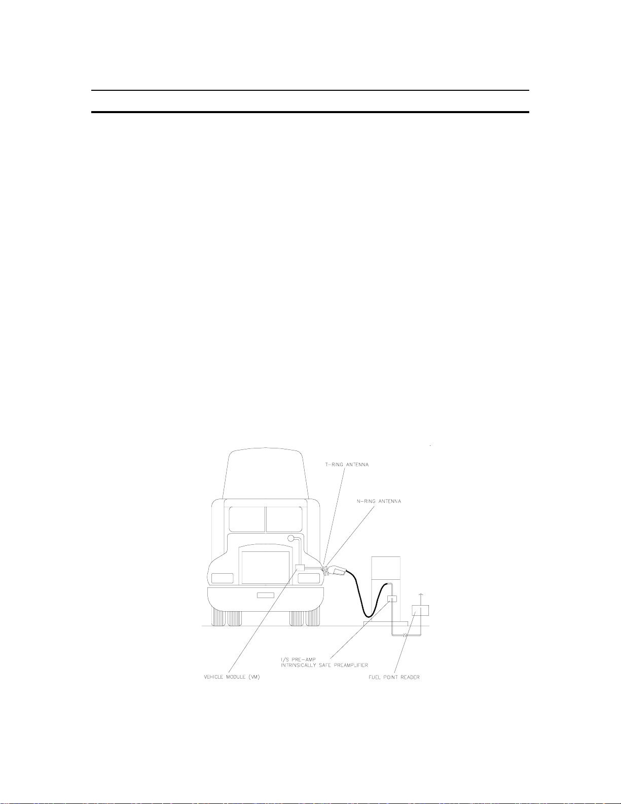
SYSTEM OVERVIEW
Fuel Point adapts to Listed GASBOY fuel management systems for has sle-free fueling. System
applications determine actual components required. Your system will consist of the following
components:
a GASBOY fuel management system (FMS) (Listed models 1000, 1000P, or 2000S CFN)
●
Fuel Point Reader (FPR)
●
Pumps/dispensers m odified using Listed Dispenser and Hose Retrofit Kits (consisting of I/S
●
Pre-amp and one or two kits)
T-Ring Tank Antenna (See Manual C35699)
●
Vehicles equipped with materials from Vehicle Installation Kits (See Manual C35699)
●
Vehicle Module(s) (VM's)
●
03/28/03 1-3
Page 8

GASBOY Fuel Point System
FUEL POINT READER
Description
The Fuel Point Reader (FPR) is housed in a weatherpr oof cabinet. It is micropr ocessor-based
and consists of modular components and configured software. It communicates vehicle
information to the GASBOY fuel management system c ontroller for up to eight fueling positions.
Multiple fuel point readers may be used for systems with m ore than eight f ueling positions. When
used with the CFN II FMS, multiple FPR's may be connected for controlling up to 32 fueling
positions.
Location
The Fuel Point Reader may be factory-mounted to a new FMS, located independently on the
island, or retrofitted to an existing GASBOY FMS, as described in Section 4. It can also be wallmounted inside a building, but this option may increase the installation costs because each NRing requires a two-wire run to the FPR. W hen wall-mounted, the FPR should be located near
other fuel system components such as pump control unit, circuit breakers, wiring trough, etc..
1-4 03/28/03
Page 9
Introduction
DISPENSER RETROFIT KITS
Dispenser retrofit k its provide the wires, couplings, and hardware needed to m odify the hose and
nozzle to accept the fuel point hardware. They also contain the I/S Pre-amps and N- ring nozzle
antennas. These kits are described in detail in the Dispenser and Hose Retrofit Installation
Manual, C35593.
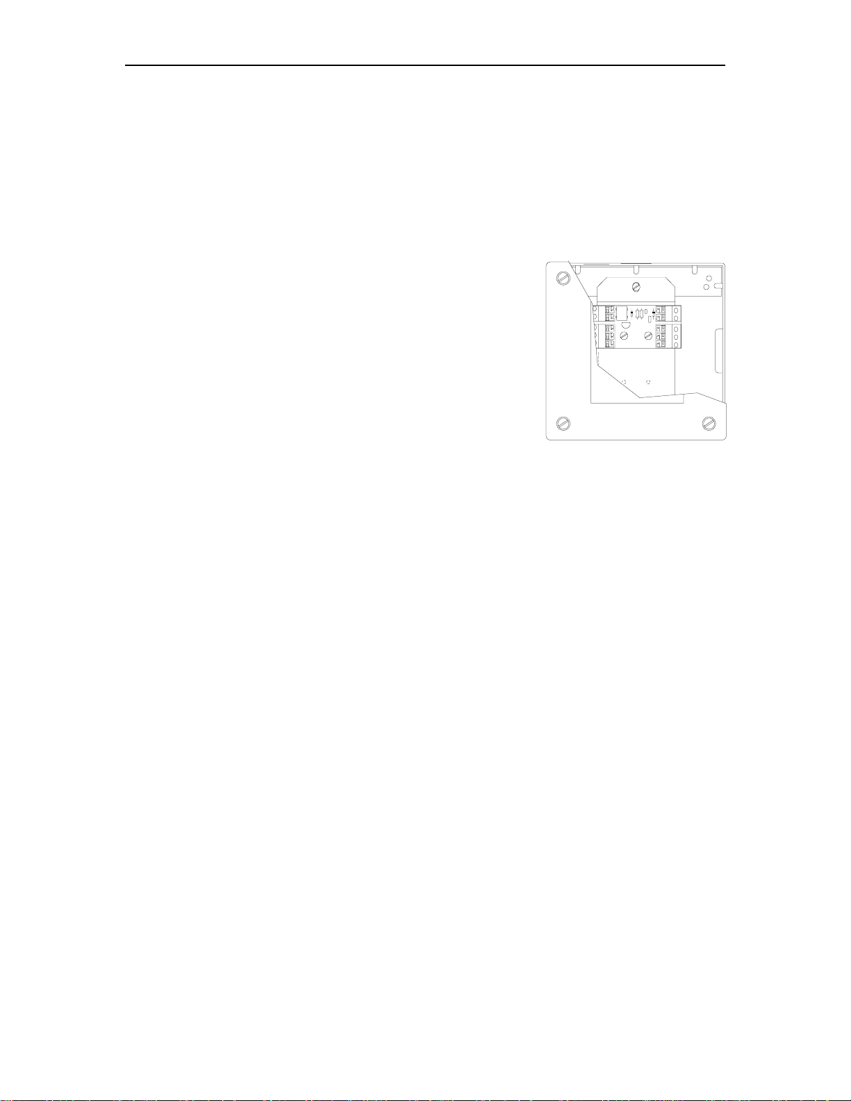
I/S Pre-Amplifiers (I/S Pre-Amp)
The I/S Pre-Amp assemblies are small PCB's mounted in
junction boxes within the dispenser. An I/S Pre-Am p am plifies
the antenna signal to the FPR, assuring reliable
communic ation. The Pre-Amps come factor y-installed inside
a metal junction box. Wiring between the I/S Pre-Amp and the
Fuel Point Reader is shown in the System Wiring section of
this manual. W iring between the I/S Pre-Amp and the nozzle
ring is shown in the Dispenser and Hose Retrofit Installation
Manual, C35593.
N-Ring Nozzle Antenna
The N-Ring nozzle antenna mounts on the base of the nozzle spout and is concealed by a spec ial
nozzle cover. It is connected to the I/S Pre-Amp via antenna wire that is run down the inside or
outside of the hose. It transmits/receives com munication to/from the vehicle's T-Ring antenna.
Installation of the N-Ring is detailed in the Dispenser and Hose Retrofit Installation Manual,
C35593.
VEHICLE COMPONENTS
Each vehicle is modified to work with the Fuel Point system by installation of a T-Ring tank
antenna connected to a Vehicle Module (VM). Vehicle installation kits provide the required
elements to install the T-ring and VM. Vehicle kit installation instructions are contained in the
Vehicle Module (VM) Installation Manual, C35699.
03/28/03 1-5
Page 10

Page 11

Section 2
CONDUIT LAYOUT AND FPR INSTALLATION
PURPOSE
Use this section for detailed planning of the installation of your system. This section covers
conduit requirements and shows conduit layout examples for basic system configurations.
Careful planning of the site layout will help eliminate possible problem s with the start-up of your
system and will ensure continued, reliable system operation.
03/28/03 2-1
Page 12

GASBOY Fuel Point System
CONDUIT REQUIREMENTS
The conduit requirements outlined in this section are relevant to all components mak ing up the
GASBOY system. The GASBOY Warranty will not apply to any system deviating from the
requirements outlined in this section.
All wiring and conduit runs must conf orm with all building/fire c odes, all Federal, State, and Local
codes, National Electrical Code (NFPA 70), NF PA 30, and Automotive and Marine Service Station
Code (NFPA 30A) codes and regulations. Canadian user s must also com ply with the Canadian
Electrical Code.
All wiring (AC and DC) connecting the different components of the Fuel Point System and all
communica tion equipment signal wires must be installed underground in thread ed, rigid, metal
conduit. PVC IS NOT ACCEPTABLE. High voltage AC power wires must be installed in
separate conduit from the low voltage DC signal wires; they cannot be run in any sort of com mon
conduit or trough. Exceptions to these requirem ents are noted in Section 3, Communication
Requirements (RS-485). I/S wires must be in separate conduit from all AC or DC wires.
All holes and knockouts accept up to 3/4" conduit. All conduit must be connected to the
components through the holes and k nockouts provided by the factory. Do not mak e any other
holes in these units. If alternate holes are required, contact GASBOY for approval first.
The chart below shows conduit capacity for rigid metal conduit with 50% fill of gas- and oilresistant wire. Use this chart as a guideline to determine the proper conduit sizes for the
GASBOY Fuel Point System wiring. When planning the orientation of the wire runs, f ollow the
applicable GASBOY wiring diagrams and consider the layout of the com ponents at the s ite. Long
runs or a large number of bends may require you to increase conduit size over what is listed.
Table 2-1. Conduit Size Chart
2-2 03/28/03
Page 13

Conduit Layout and FPR Installation
CONDUIT LAYOUT/INSTALLATION SPECIFICATIONS
1. All wiring must be installed and used in accordance with all building/fire codes, all Federal,
State, and Local codes, National Electrical Code (NFPA 70) , NFPA 30, and Automotive and
Marine Service Station Code (NFPA 30A) codes and regulations. Canadian users must also
comply with the Canadian Electrical Code.
2. Power must come from a separate dedicated circuit break er rated at no less than 10 AMPS
or may share the fuel management system breaker. W hen mounted to an island pedestal
(factory or retrofit), the FPR will get its power from the pedestal device via a GASBOYsupplied AC power cable.
3. All conduit must be rigid metal to provide the necessary shielding.
4. All conduit must be run underground, not overhead.
5. The I/S Pre-Amp comes fac tory-installed in a metal junction box and mounts in the bas e of
the pump or dispenser. Twin pumps or dispensers have two Pre-Amps mounted in the same
junction box. The box is secured by threading onto conduit. It can be mounted wherever it is
convenient as long as it does not interfere with other dispenser com ponents. The junction
box has 1/2 inch hubs, so you need to use a reducer if running larger conduit for the I/S
wiring. Strain relief connectors must be used to protect the N-ring wiring entering the box.
I/S Pre-Amp wires are intrinsically safe and must be in a separate conduit from any AC
or DC wires. The distance between the Pre-Am p and the Fuel Point Reader c annot exc eed
1000 feet.
6. It is recomm ended that the RS-485 wiring be in a separate m etal c onduit f rom any AC wires.
However, the RS-485 wires may be run in the AC conduit if the requirements outlined in
Communication Requirements (RS-485) in Section 3 are followed.
7. Use the wire size chart (Table 4-1) to determine the wire gauge.
8. Use the conduit size chart (Table 2-1) to determine the size according to the number of wires
and wire gauge.
9. Consult the applicable section of this manual for specific system installation requirements.
6213 2-3
Page 14

GASBOY Fuel Point System
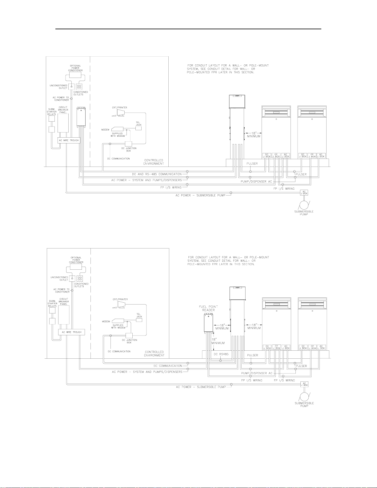
Conduit Layout - Series 1000 FMS with FPR
Conduit Detail for FPR Mounted on Fuel Management System Pedestal
2-4 03/28/03
Page 15

Conduit Layout and FPR Installation
Conduit Layout - CFN FMS with Pedestal Pump Control and Pedestal-Mounted FPR
Conduit Detail for FPR Mounted on Fuel Management System Pedestal
6213 2-5
Page 16

GASBOY Fuel Point System
Conduit Layout - CFN FMS with Wall-Mounted PCU and Wall-Mounted FPR
Conduit Layout - CFN FMS with Pedestal Pump Control and Pole-Mounted FPR
2-6 03/28/03
Page 17
Conduit Layout and FPR Installation
Conduit Layout - Series 1000 FMS with Wall-Mounted FPR
Conduit Layout - Series 1000 FMS with Pole-Mounted FPR
6213 2-7
Page 18
GASBOY Fuel Point System
Conduit Detail for Wall- or Pole-Mounted FPR
2-8 03/28/03
Page 19

Section 3
SYSTEM WIRING
GENERAL WIRING PRECAUTIONS
The quality of the electrical installation is a m ajor factor in maintaining proper saf ety levels and
providing trouble-free operation of your GASBOY Fuel Point Reader. To ensure a quality
installation, follow these rules:
1. All wiring must be installed and used in accordance with all building/fire codes, all Federal,
State, and Local codes, National Electrical Code (NFPA 70) , NFPA 30, and Automotive and
Marine Service Station Code (NFPA 30A) codes and regulations. Canadian users must also
comply with the Canadian Electrical Code.
2. Use rigid metal conduit and insulated gasoline- and oil-resistant wiring of the proper size.
3. Wire c onnections m ust be tightly spliced and secured with a wire nut; close of f the open end
of the wire nut with electrical tape.
4. Install an emergency power cutoff. In addition to circuit breaker requir ements of NFPA 70,
NFPA 30, NFPA 30A, and the Canadian Electrical Code (Canadian users only), a single
control which simultaneously removes AC power from all site dispensing equipment is
recomm ended. This control must be readily access ible, clearly labeled, and in accordance
with all local codes.
In a fuel management s ystem applic ation, the EMERG ENCY STO P button on the island c ar d
reader and/or the EMERGENCY STOP and STOP k eys on the console (if applicable) do not
remove AC power from equipment and under certain conditions, will not stop product flow.
In order to provide the highest level of safety to you, your employees, and customers, we
recommend that all employees be trained as to the location and procedure for turning off
power to the entire system.
WARNING
To reduce the risk of electrical shock when servicing, turn off all power to the
pump/dispenser. In submersible pump applications, turn off all power to the submersible
pump and any other dispensers which use that s ubmersible pump. AC power c an feed back
into a shut-off dispenser when dispensers share a common submersible pump or starter
relay.
AVERTISSEMENT
Pour réduire le risque de choc électrique lors de l'entretien/révision, coupez totalement le
courant à la pompe/distributeur. Dans les applications de pompe immersible, coupez
totalement le courant à la pompe immersible et tous autres distributeurs qui utilisent la
pompe immersible. Le courant alternatif peut alimenter de nouveau un distributeur à l'arrêt
quand les distributeurs partagent une pompe immersible commune ou un relais de
démarrage.
03/28/03 3-1
Page 20

GASBOY Fuel Point System
SYSTEM WIRING DIAGRAM
3-2 03/28/03
Page 21

System Wiring
POWER REQUIREMENTS
Pedestal Mount
AC power for a pedestal-mounted FPR will come from the Fuel Management System via a
GASBOY-supplied AC power cable. This means the VA rating for the entire pedestal
assembly will be the sum of the ratings on the tags for both the FMS and the FPR.
Wall or Pole Mount
AC power for the wall- or pole-mounted FPR must come from a separate, dedicated circuit
breaker rated at no less than 10 AMPS or m ay share the fuel m anagement s ystem breaker. No
other equipment, including the system's pumps or dispensers, m ay be powered from this break er.
Whenever poss ible, one breaker should be used to supply the FMS components, data term inal,
and modem. However, it is acceptable to supply the power to the different FMS components and
accessories from multiple breakers within the same breaker panel and the same phase of
power. When necessary, power for the data terminal or modem may be supplied from a
separate, dedicated breaker located in a dif ferent breaker panel. The s ystem requir es 120 VAC +
10% 47-63 HZ for power.
Proper system grounding is an extremely important part of the system installation. As with the AC
power, the grounds for all components should return to the same break er panel. This helps to
assure a common ground thr oughout the system which is nec ess ary for protection of the circuitr y.
Grounds for all system devic es should be wired to the break er panel gr ound bus bar which in tur n
should be grounded to a ground rod. A conduit ground does not provide a sufficient ground. It is
recommended that the neutr al and ground bus bars be bonded together when it is not prohibited
by local codes.
The AC wire size for power of the FPR mus t be 14 AWG or larger. T his gauge of wire will be
sufficient for runs of up to 300 feet from the breaker panel to the system. Components with
distances over 300 feet m ust use 12 AWG wire or larger. All wire should be st randed. When
connecting AC power wires to FPR, keep wire slack near bottom of cabinet.
RS-485 COMMUNICATION REQUIREMENTS
RS-485 wiring is used for communication between the FPR and FMS components. This
communica tion takes place over the RS-485 field wiring. The following installation requirements
must be followed when installing the RS-485 communication lines:
1. All wiring must be installed and used in accordance with all building/fire codes, all Federal,
State, and Local codes, National Electrical Code (NFPA 70) , NFPA 30, and Automotive and
Marine Service Station Code (NFPA 30A) codes and regulations. Canadian users must also
comply with the Canadian Electrical Code.
2. Cable: Twisted pair shielded cable is highly recom mended f or RS-485 wiring. Although it is
recommended that wires be run in a conduit separate f rom AC wires, they can be com bined
in the same conduit with AC wires providing UL-Listed cable with the following specifications
is used:
Conductor: 18 AWG stranded wire. 2 twisted-pairs.
Shield: Foil-wrapped 100% coverage and/or tinned copper braid 90% coverage
Drain Wire: Stranded, tinned copper, 20 AWG or larger/or braided shield
Voltage Rating: Maximum operating voltage of 600V
Environmental: Gas- and oil-resistant; suitable for wet or dry locations.
03/28/03 3-3
Page 22

GASBOY Fuel Point System
GASBOY can supply Belden 1063A (P/N C09655) which is a UL-Listed, 4- conductor cable
that meets the requirements lis ted above. NOTE: Belden 1063A is UL-Listed but not CSA
listed.
Cable with a voltage rating of less than 600V must be installed in a conduit separate f rom all
AC wires.
3. Conduit: When using the r ecommended shielded, twisted-pair cable des cribed above, the
cable can be run with AC wires in metal conduit. T he shield drain wire m ust be c onnected to
the system AC ground. Only AC wires for the system and pumps can be installed in the AC
conduit. Do not run the cable outdoors without the use of metal conduit. Do not run this
cable overhead, outdoors.
The cable can be run indoors without the use of metal conduit. The shield drain wire must be
connected to the system AC ground.
If using cable other than that recommended above, the RS- 485 field wires must be inst alled
in a metal conduit separate from any AC wires.
4. Distance: The following distances must be adhered to when installing the RS-485 field
wiring.
Wiring over 100 feet must meet the specifications outlined in Cable above.
●
The distance from the FPR to the FMS is limited to 1000 feet.
●
5. Connections: See the Wiring Diagrams later in this section for proper connection of the
RS-485 field wiring to the FMS components.
N-RING WIRING REQUIREMENTS
N-Ring wiring between the FPR and the pump must be 18 AWG, gas- and oil-resistant wire.
Heavier gauge wire will not fit into the connectors on the I/S or Pre- Amp PC boar ds. To pres erve
intrinsic safety, N-Ring wiring must be in separate conduit from AC and DC, RS-485, or pulser
wiring.
3-4 03/28/03
Page 23

System Wiring
FIELD WIRING, I/S PRE-AMP TO FPR
The following diagram shows the wiring between the I/S PCB in the Fuel Point Reader and the I/S
Pre-Amp PCB located in the pum p junction box. These connections should be made after the
FPR mounting is complete, as described in Section 4.
1. Remove the wiring cover protecting the terminal blocks on the I/S PCB in the FPR.
2. Strip about 3/8" of insulation from each wire end. To connect the wire, push down on the
orange tab and insert the wire. Release tab and gently tug on the wire to verify a tight
connection.
CAUTION: Wire polarity is not important, but connection to the wrong side of the pre-amp
assembly will cause damage!!! Always make sure the IC chip s ide of the PreAmp PCB connects to the FPR and the diode side connects to the N-Ring hose
cable.
3. Replace the wiring cover protecting the terminal blocks on the I/S PCB.
IMPORTANT: Mak e sure the cover is tight against the chassis, with no more tht 1/16 inc h
gap around all sides, to preserve the intrinsic safety of the area.
03/28/03 3-5
Page 24

GASBOY Fuel Point System
FIELD WIRING, SERIES 1000 AC POWER AND RS-485
Wall- or Pole-Mounted FPR To Series 1000
If your Fuel Point Reader was installed on your FMS at the factory, you do not need to reference
this field wiring diagram. If you are retrofitting an existing FMS, s ee Section 4. For wall- or polemounted FPR's, use wire type and size as described earlier in this section.
NOTE: If two auxiliary terminal blocks are present (as shown), the bottom TB is for Fuel
Point and the top is for tank monitor.
3-6 03/28/03
Page 25

System Wiring
FIELD WIRING, CFN AC POWER AND RS-485
Wall-or Pole-Mounted FPR To CFN
If your Fuel Point Reader will be wall- or pole-mounted for use with CFN, f ollow this diagram. Use
wire type and size as described earlier in this section.
Pedestal-Mounted to CFN Islander Satellite
If your Fuel Point Reader was installed on your CFN Islander satellite pedestal at the f actory, you
do not need to do any field wiring between the FPR and the satellite.
Pedestal-Mounted to CFN ICR
If your Fuel Point Reader was installed on your CFN ICR pedestal at the fac tory, follow the wiring
diagrams in Section 4 to connect the AC and RS- 485 c ommunications cables to the ICR. T he AC
and RS-485 cables are factory-installed on the FPR side only.
03/28/03 3-7
Page 26

Page 27
Section 4
FIELD RETROFIT INSTRUCTIONS
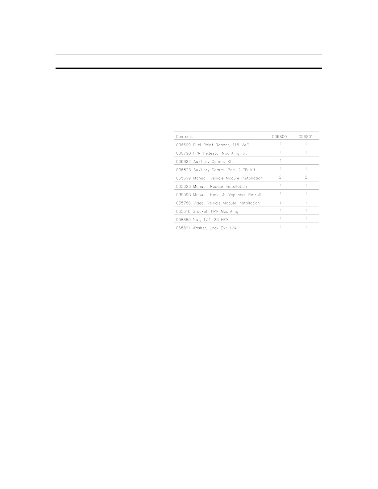
FIELD UPGRADE KITS
Use this section when you are installing a Fuel Point Reader (FPR) for use with an existing FMS.
If your FPR was shipped from the factory already attached to a GASBOY Fuel Management
System Pedestal, you do not need to reference this section.
Several kits exist to help you in the
retrofit. Use the chart on the right to
identify the appropriate retrofit kit
based on your system type.
Use Kit C06800 to add a FPR to a
Series 1000.
Use Kit C06801 to add a FPR to a
Series 1000 with tank monitor
interface, Series 1000P with printer, or
2000S CFN System.
FPR FIELD MOUNTING OPTIONS
There are four FPR field mounting options:
Wall mount to a studded wall
●
Wall mount to a masonry wall
●
Pole mount
●
FMS pedestal mount
●
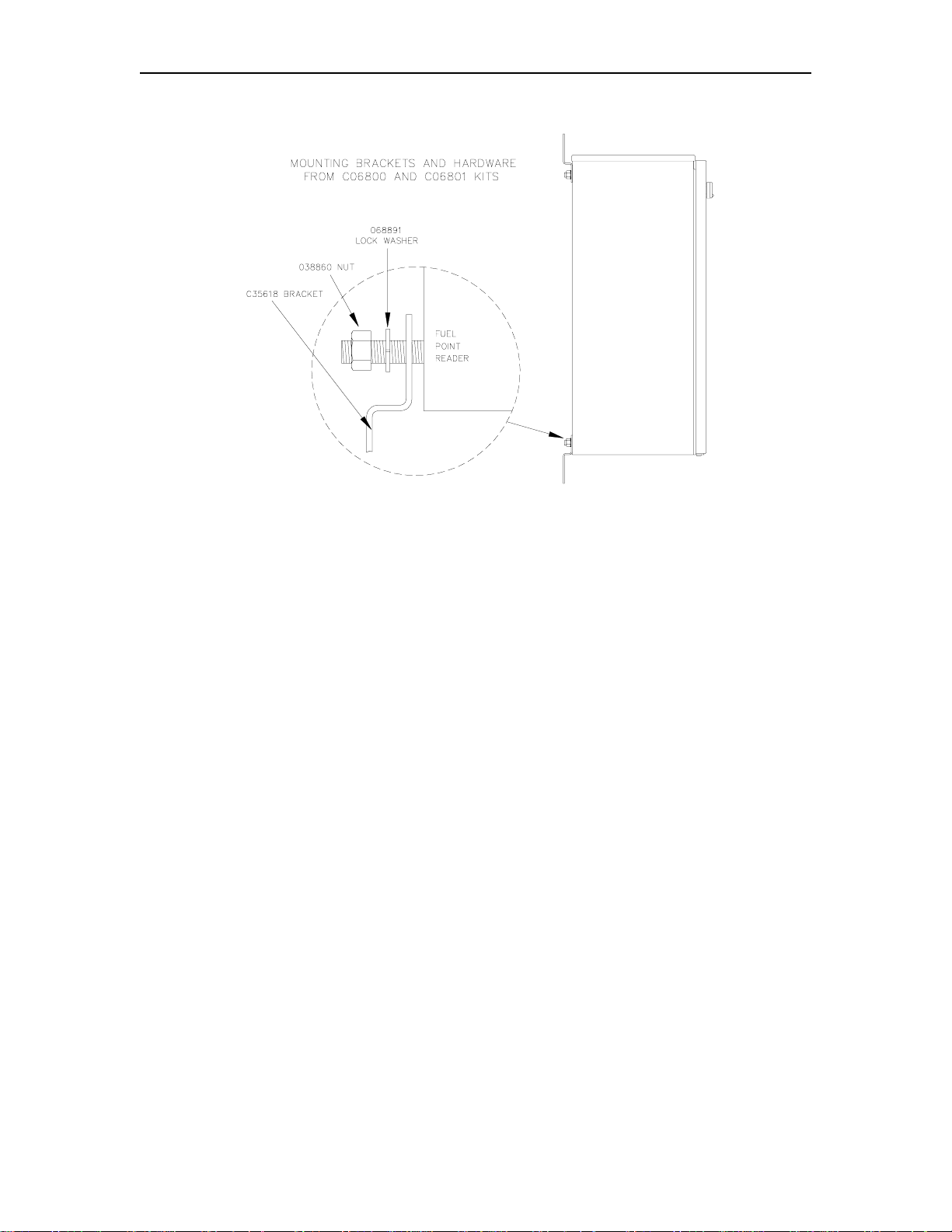
ATTACHING FPR MOUNTING BRACKETS
Before mounting the FPR to a wall, pole, any FleetKey pedestal, or a CFN pedestal with built-in
Pump Control Unit, you must first attach m ounting br ackets fr om the C06800 or C06801 upgrade
kit. If the FPR is to be mounted to a CFN standard (blank) pedestal, or CFN receipt printer
pedestal, skip this step, as the mounting brackets are not used.
03/28/03 4-1
Page 28
GASBOY Fuel Point System
WALL-MOUNT - STUDDED OR MASONRY WALL
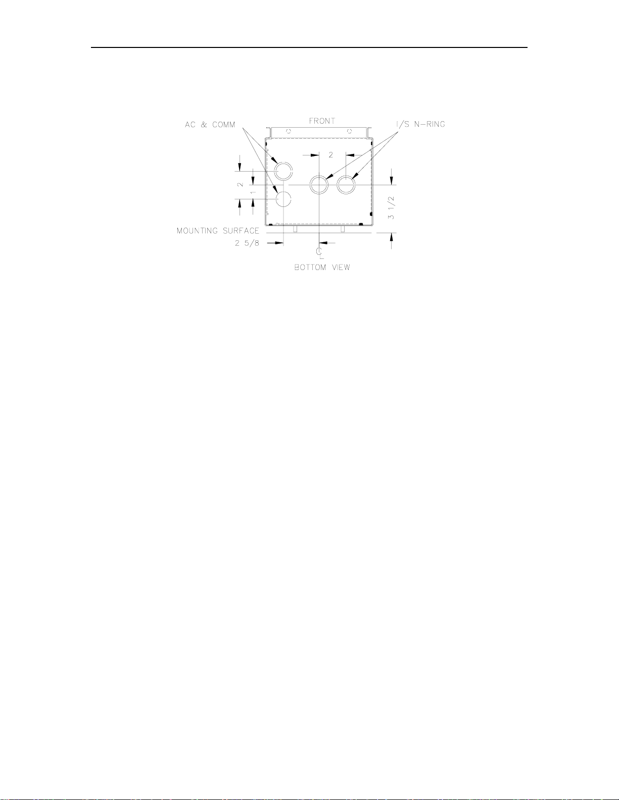
1. There is a nylon plug and nut included with the FPR. It must seal the un-used m achined
conduit hole. When the FPR is mounted to a wall, the hole to seal is on the back of the FPR.
Use the nylon plug and nut, along with an o-ring from the C06790 kit.
2. Refer to the FPR dimension drawing on the next page.
For a studded wall, use 3/8" diameter lag bolts in the two center holes to attach the FPR to a
wall stud.
For a masonry wall, use 1/4" diameter bolts and wall anchors in the four outer holes to mount
the FPR.
3. Go to Section 3, System Wiring.
POLE-MOUNT
1. There is a nylon plug and nut included with the FPR. It must seal the un-used m achined
conduit hole. When the FPR is mounted to a pole, the hole to seal is usually on the back of
the FPR. Use the nylon plug and nut, along with an o-ring from the C06790 kit.
2. Refer to the FPR dimension drawing on the next page. Use 3/8 inch diameter U-Bolts in the
four oval holes to attach the FPR to a 2-inch through 3-inch diameter pole.
3. Go to Section 3, System Wiring.
4-2 03/28/03
Page 29

Field Retrofit Instructions
FPR DIMENSIONS
FMS PEDESTAL MOUNT
C06790 FPR Pedestal Mounting Kit
The C06790 kit (itemized below) contains the parts needed for mounting the FPR to a FMS
pedestal.
Qty Part No. Description
4 051790 Bolt, 1/4-20 x 1/2
4 068891 Washer, 1/4 External Locking
4 068005 Washer, 1/4 Plated
4 C08875 Washer, 11-32 x 5/8 Round Gasket
4 038860 Nut, 1/4 Hex
2 039210 Nut, 3/4 NPT
1 021042 Conduit, 3/4 Close Nipple
2 068444 Washer, 3/4 Conduit
2 048899 O-Ring, 1" ID
2 C09548 Bushing, 5/8" Snap
1 C06778 Cable Assy, FPR 115V Power
1 C06779 Cable Assy, FPR RS-485 Comm.
03/28/03 4-3
Page 30

GASBOY Fuel Point System
Attaching the FPR to all FleetKey Pedestals, or to CFN Pedestal with Built-in Pump Con trol
Unit
WARNING: Before proceeding, move the GASBOY fuel management system/island
reader unit to a safe location away from the fueling island.
This procedure assum es the fuel management system was installed accor ding to the applicable
codes and according to the specifications set forth in the GASBOY fuel management system
Installation Manual. Be sure to follow these same r estrictions and guidelines when re-installing
the FMS back onto the island.
1. Turn off all break ers supplying power to the Fuel Management System pedestal, inc luding
breakers supplying power to pumps that are contr olled through the pedestal. Remove the
pedestal's side access covers. Mark and detach all wiring coming from the pedestal
conduits. Unbolt and remove the pedestal from the island. Take the pedestal to a safe
location away from the fuel island.
2. Measure the height of the internal barrier plate and m ark a horizontal line on the outside of
the pedestal as shown. Measure to the center of the pedestal and mark a vertic al line as
shown. Using the measurements from the diagram below, mark and drill four mounting
holes. For the conduit hole, drill a pilot hole, then finish with a 1-1/8" diameter punch.
3. Hold the FPR against the rear of the pedestal to make sure the five holes line up. Attach the
FPR using the four 051790 bolts, 068891 lock washers, 068005 flat washers, C08875 gasket
washers, and 038860 nuts as shown on page 4-6. The steel washers are used on the
outside, under the bolt head and the gasket washers go between the FPR br ac k ets and F MS
pedestal.
4. Proceed to Completing the FPR Mounting - All Pedestal Types.
4-4 03/28/03
Page 31

Field Retrofit Instructions
Attaching the FPR to CFN Standard (Blank) and CFN Printer Pedestals
WARNING: Before proceeding, remove the rear access cover of the CFN pedestal to a
safe location away from the fueling island.
1. Turn off all breakers supplying power to the Fuel Management System pedestal. Rem ove
the pedestal's side access covers. Remove the pedestal's rear ac cess cover and tak e it to a
safe location away from the fuel island.
2. Measure to the center of the cover and mark a vertical line as shown. Using the
measurements from the diagram below, mark and drill four m ounting holes. For the conduit
hole, drill a pilot hole, then finish with a 1-1/8" diameter punch.
3. Hold the FPR against the rear of the access cover to make sure the five holes line up.
Attach the FPR using the four 068005 flat washers , C08875 gasket washers, 068891 lock
washers, and 038860 nuts as shown on the next page. Be sur e to use the gasket washers
on the outside of the cover.
4. Proceed to Completing the FPR Mounting - All Pedestal Types.
03/28/03 4-5
Page 32

GASBOY Fuel Point System
4-6 03/28/03
Page 33

Field Retrofit Instructions
Completing the FPR Mounting - All Pedestal Types
1. The Fuel Point Reader comes shipped with a nylon plug and nut. They may be installed in
one of the two machined conduit holes. When the F PR is pedestal-mounted, the plug and
nut must be installed in the m achined conduit hole in the bottom of the FPR as shown in the
drawing on the next page.
2. Thread a 039210 nut onto the 021042 conduit nipple as far as you can, typically a few turns.
Add a 068444 washer, then a 048899 O-ring against the inside of the nut.
3. Insert the conduit assembly into the FPR, through the large hole on the rear wall. W orking
from inside the FMS pedestal, ins tall a 048899 O-ring, 068444 washer, and 039210 nut on
the conduit nipple. Tighten the nuts on both ends of the nipple. Snap a C09548 bushing into
each end of the conduit.
4. The C06778 and C06779 cables will be used in the wiring diagrams at the end of this
section.
5. See Section 2 for the applicable conduit installations.
03/28/03 4-7
Page 34

GASBOY Fuel Point System
SERIES 1000 UPGRADE KITS
As mentioned earlier, your Fuel Point shipm ent may have included various upgrade kits for the
Series 1000 System. The Series 1000 needs the Auxiliary Communications PCB to communicate
to the Fuel Point Reader. If your Series 1000 doesn't have a tank m onitor interface or a receipt
printer, start at the next section, Adding Auxiliary Communications and Comm. Port 1 Using
the C06822 Kit. If your Series 1000 has a tank m onitor interface, you already have the Auxiliary
Communications PCB installed; proceed to Adding Comm. Port 2 Using the C06823 Kit. If your
Series 1000 has a receipt printer, you already have the Auxiliary Communications PCB and Port 1
cable installed; proceed to Field Wiring, Series 1000 AC Power and RS-485.
Adding Auxiliary Communications and Comm. Port 1 to Series 1000 Using the C06822 Kit
The C06800 Fuel Point system contains a C06822 k it f or adding the comm unic ations board to the
Series 1000. It also contains a spare cable that can be us ed for a tank monitor , T he contents of
the C06822 kit are shown below.
Qty Part Number Description Qty Part Number Description
2 C04291 Screw, 6-32 x 3/4 1 C05918 Cable, Auxiliary Comm.
1 067765 Fiber Washer 2 C04030 Screw, 8-32 x 3/4
2 C02896 PCB Support 1 C01695 Decal, "AUX. 12345 PORT"
1 C05909 PCB, Auxiliary Comm.
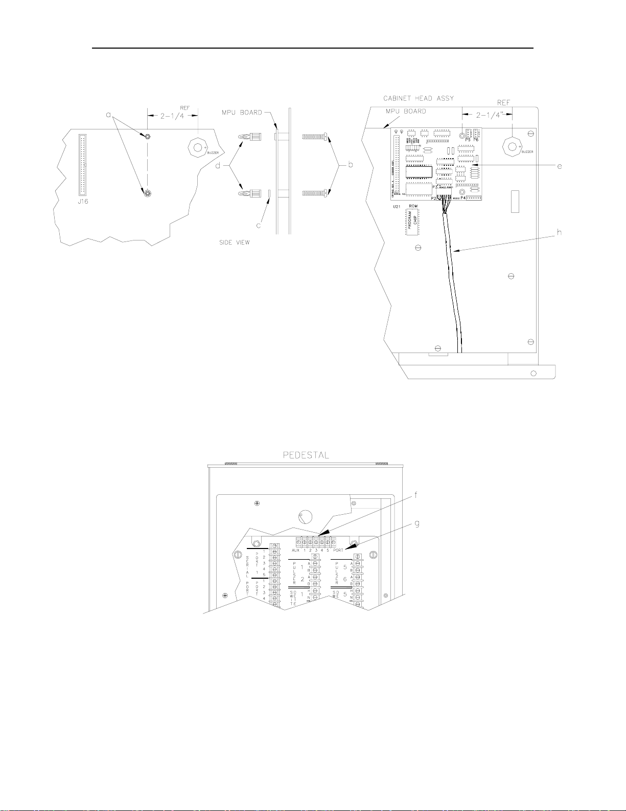
1. Remove the housing wrapper and access panels on the Series 1000.
NOTE: Refer to the drawings on the next page for this procedure.
2. Remove the two screws (a) located approximately 2-1/4 inches to the lef t of the buzzer on
the MPU board.
3. Install two C04291 screws (b) in their place. Start the screws from the inside so that the
threads protrude out through the MPU board.
4. The top screw already has a fiber washer glued to the MPU board. Add an 067765 fiber
washer to the bottom screw (c).
5. Add two C02896 PCB supports to the screws (d).
6. Push the C05909 Auxiliary Communications PCB (e) onto the standoffs. Make sure that
connector P1 on the bottom of the Communications PCB m ates properly with connector J16
on the MPU PCB.
7. Attach the C05918 terminal block and cable (f) to the Series 1000 pedestal using two
C04030 screws. When installing the cable, the red wire from the terminal block must be on
the left.
8. Place the C01695 decal under the terminal block as shown (g).
9. Pass the cable (h) through the large nylon bushing at the top of the pedestal. Route the
cable under the MPU board and attach it to P3 on the Auxiliary Comm. PCB (e).
10. Proceed to the next section, Adding Comm. Port 2 to Series 1000 Using the C06823 Kit.
4-8 03/28/03
Page 35
Field Retrofit Instructions
03/28/03 4-9
Page 36
GASBOY Fuel Point System
Adding Comm. Port 2 to Series 1000 Using the C06823 Kit
The C06800 and C06801 Fuel Point systems contain a C06823 k it for adding the Comm . Port 2
cable to the Series 1000. The contents of the C06823 kit are shown below.
Qty. Part Number Description
1 C05918 Cable, Auxiliary Comm.
1 C35621 Bracket, Aux. Comm.
2 C04030 Screw, 8-32 x 3/4
1 C01695 Decal, "AUX. 12345 PORT"
1 C08938 Terminal Block Jumper
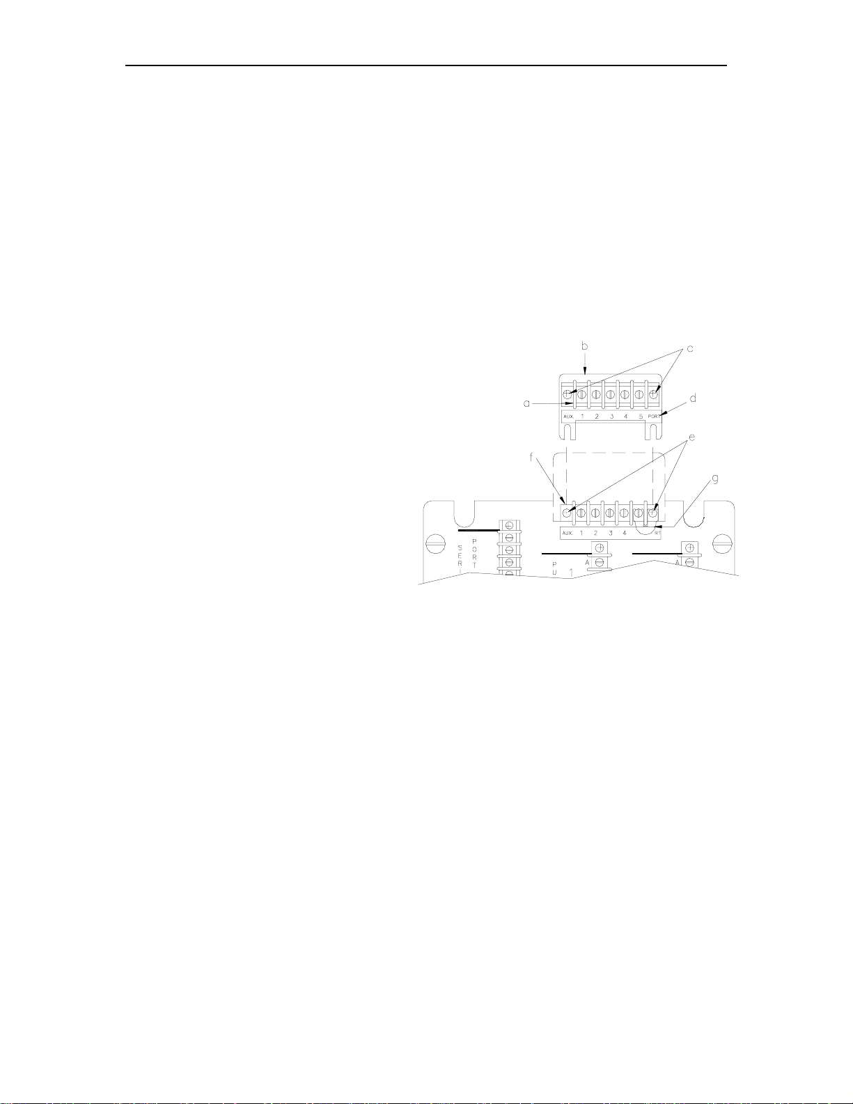
1. Remove the housing wrapper and access panels on the Series 1000.
2. Attach the C05918 terminal block and
cable assembly (a) to the C35621
bracket (b) using two C04030 screws
(c). W hen installing the assembly, the
red wire from the term inal block must
be on the left.
3. Place the C01695 decal below the
terminal block (d).
4. Loosen, but do not remove, the two
screws (e) holding the Auxiliary Comm.
Port 1 terminal block to the pedestal.
Place the C35621 bracket assembly
behind the terminal block (f) in the
pedestal.
5. Add the C08938 jumper (g) to the two
right-most screws of the Fuel Point
(bottom) terminal block.
6. If the Series 1000 was previously interfacing to the tank monitor, the tank monitor's
communication wiring is on the bottom terminal block. You must move the tank monitor
wiring from the bottom term inal bloc k to the top one. The other end of the top ter m inal block
cable must plug into P4 on the Auxiliary Comm . PCB (h) . Note that P4 is an RS-232 port. If
the tank monitor was previously connected to P3, also RS-232, then no re- wiring is needed.
If the tank monitor was previously connected to P2, RS-422, you must consult your tank
monitor manual to see what changes are required for RS-232 communications. When
routing the cable to the Auxiliary Comm. PCB, pass it through the lar ge nylon bushing where
the head joins the post. Pass it under the MPU PCB so it comes out in front of the boards.
4-10 03/28/03
Page 37

Field Retrofit Instructions
7. Pass the cable from the bottom
terminal block in the same
fashion and attach it to P3 (Port
1) on the Auxiliary Comm. PCB
(i). This will be the FPR port.
8. Proceed to the next section,
Field Wiring - Series 1000 AC
Power and RS-485.
03/28/03 4-11
Page 38

GASBOY Fuel Point System
FIELD WIRING, SERIES 1000 AC POWER AND RS-485
Wall- or Pole-Mount
See Section 3, Field Wiring.
Pedestal-Mount
When installing the FPR to the FMS pedestal, use the C06778 and C06779 cables from the
C06790 mounting kit. If two auxiliary terminal bloc ks are present (as s hown), the bottom TB is f or
tank monitor and the top is for Fuel Point.
4-12 03/28/03
Page 39

Field Retrofit Instructions
FIELD WIRING, CFN AC POWER AND RS-485
Wall- or Pole-Mount FPR to CFN ICR
See Section 3, Field Wiring.
Pedestal-Mount FPR to CFN ICR
When installing the FPR to the FMS pedestal, use the C06778 and C06779 cables from the
C06790 mounting kit.
03/28/03 4-13
Page 40

GASBOY Fuel Point System
Wall- or Pole-Mount FPR to CFN Pedestal PCU
See Section 3, Field Wiring.
Pedestal-Mount FPR to CFN Pedestal PCU
When installing the FPR to the FMS pedestal, use the C06778 and C06779 cables from the
C06790 mounting kit.
4-14 03/28/03
Page 41

Field Retrofit Instructions
Wall- or Pole-Mount FPR to CFN Islander Series
See Section 3, Field Wiring.
Pedestal-Mount FPR to CFN Islander Series
When installing the FPR to the FMS pedestal, use the C06778 and C06779 cables from the
C06790 mounting kit.
03/28/03 4-15
Page 42

GW01 - 6/04/02 Rev. 1
WARRANTY
General Statements:
Gasboy International LLC. warrants all new equipment manufactured by Gasboy agai nst defective materi al and/or workmanship, for the warranty
period specified below, when the equipment i s installed in accordance with specifications prepared by Gas boy.
This warranty does not cover damage caused by acci dent, abuse, Acts of God, lack of surveillance of autom atic recording systems, negligence,
mis-application, faulty installation, i mproper or unauthorized maintenance, i nstallation or use in violati on of product manuals, i nstructions, or warnings.
Under no circumstanc e shall Gasboy be liable for any indirect , special, or consequenti al damages, losses, or expenses to include, but not limited
to, loss of product, los s of profits, litigation fees , or the use, or inability to use, our product for any for any purpose whatsoever.
Parts Only - During the warranty period, Gasboy will, at its option, repair or replace defective parts returned transportat i on prepaid to its factory.
On-Site Labor Included - Gasboy will also provide, within the Continental United States and during the warranty period, the services of an
Authorized Service Representati ve (A SR) for on-site repair or replacem ent of defective parts.
Replacement Parts - Any system com ponents that are not part of the origi nal system order, includi ng Island Card Readers, Pump Cont rol Uni ts, etc.,
are considered replacement part s.
Equipment Term Coverage
Commercial Pumps and Dispensers
Full-Cabinet Consumer Pumps
Small Transfer Pumps, Meters,
Pressure Regulators
Keytrol One year from date of instal l ation or 18 mos. from date of
Fuel Management Systems :
- CFN/ Profit Point
- Series 1000/Fleetkey
- TopKAT
- Fuel Point Readers
(sold with new systems)
Additional Fuel Point Items:
- Fuel Point Readers sold for
retrofitting existing sys t ems.
- Fuel Point vehicle and dispenser
components.
Encoders, Embos sers, Modems,
CRTs, and Logger Printers
One year from date of installation or 18 mos. from date of
Gasboy International’s invoi ce to the purchaser, whichever
comes first.
One year from date of install a t i on or 18 mos. from date of
Gasboy International’s invoi ce to the purchaser, whichever
comes first.- Excepting the Model 2020 Hand Pump, which
has a 90-day warranty from date of GASBOY International’s
invoice.
Gasboy International’s invoi ce to the purchaser, whichever
comes first.
One year from date of start-up or 15 mos. from date of
Gasboy International’s invoi ce to the purchaser, whichever
comes first .- The basic warranty only applies to sys tems
which have been started up by a Gasboy Authorized Servi ce
Representative (ASR).
One year from date of start-up or 15 mos. from date of
Gasboy International’s invoi ce to the purchaser,
whichever comes first.
Purchased with Fuel Management Syst em (Encoders,
Embossers only):
90 days from the date of s tart-up by a Gasboy ASR, or 180
days from date of Gasboy I nternational's invoice, whichever
occurs first.
Parts and Labor.
Parts Only.
Parts and Labor.
Parts and Labor.
Parts Only.
Purchased with System
(Encoders, Embos sers only):
Parts only.
Purchased with Fuel Management System
(Modems, CRTs, and Logger Printers only):
Matches system warranty.
Purchased Separately:
90 days from date of Gasboy I nt ernational's
invoice to the purchaser.
Air Diaphragm Pumps Three years from date of purchase (for full warranty
Items not m anuf actured by Gasboy
(ex. automatic nozzles, hoses, swivels,
etc.)
Replacement Parts One year from date of Gasboy Int ernational's invoice to the
To the extent permitted by law, this warranty is made in lieu of all other warranties , express ed or i mplied, including warranties of freedom from patent
infringement, or merchant ability, or fitness for a partic ular purpose, or arising from a course of dealing or usage of trade. No one is authorized to
vary the terms of the warranty nor may anyone make any warranty of representation, or assume any liabilit y ot her t han that herein stated, in
connection with the sale described herein. The acceptance of any order by Gas boy International is expressly m ade subject to the purchaser's
agreement to these condit i ons.
description, see Price List).
Not warranted by Gasboy International (consul t original
manufacturer’s warranty).
purchaser.
Purchased with System (Modems,
CRTs, Logger Printers only):
Matches system warranty.
Purchased Separately:
Parts Only.
Parts Only.
Not Applicable.
Parts Only.
GASBOY INTERNATIONAL LLC
P.O. Box 309, Lansdale, PA 19446 ● (800) 444-5579 ● FAX: (800) 444-5569 ● www.gasboy.com
 Loading...