

Page 1
MDE-486
8F
Fuel Point PLUS
Vehicle Installation and Configuration Manual
This document is based on Orpak’s FuelOmat Gold Vehicle Installation
and Configuration Manual P/N 817407300
Page 2

SAFETY CONSIDERATIONS
Read all warning notes and instructions carefully. They are included to help you installing the Product safely
in the highly flammable environment of the fuel station. Disregarding these warning notes and instructions
could result in serious injury or property damage. It is the installer responsibility to install, operate and
maintain the equipment according to the instructions given in this manual, and to conform to all applicable
codes, regulations and safety measures. Failure to do so could void all warranties associated with this
equipment.
Remember that the fuel station environment is highly flammable and combustible. Therefore, make sure
that actual installati
a flammable environment, according to the local regulations and relevant standards.
on is performed by experienced personnel, licensed to perform work in fuel station and at
WARNING - EXPLOSION HAZARD
Read all warning notes and instructions carefully. They are included to help you installing the Fuel
Ring equipment safely in the highly flammable environment of the vehicle fuel tank. Disregarding
these warning notes and instructions could result in serious injury or property damage. It is the
installer responsibility to install, operate and maintain the equipment according to the instructions
given in this manual, and to conform to all applicable codes, regulations and safety measures.
Failure to do so could void all warranties associated with thi
s equipment.
Remember that the fuel vehicle fuel tank is highly flammable and combustible. Therefore, make
sure that actual installation is performed by experienced personnel, licensed to perform work in
fuel stations, cars and highly flammable environments.
When working on fuel tank inlet, make sure it is completely empty and closed.
The fumes are volatile and hence harmful to your health, if breathed for an extended period.
WARNING – PASSING VEHICLES
When working in any open area of vehicle fuel tank, beware of passing vehicles that could hit you.
Block off the work area to protect yourself and other persons. Use safety cones or other signaling
devices.
WARNING
Components substitutions could impair intrinsic safety.
Attaching unauthorized components or equipment will void your warranties.
CAUTION
Do not attempt to make any repair on the printed circuit boards residing in the Product, as this will
void all warranties related to this equipment.
Page 3

WARNING
When using the glue, carefully use and apply the glue over the surfaces in order to prevent any glue
leakage on the vehicle, to avoid any damage to the vehicle.
PROPRIETY NOTICE
This document contains propriety and confidential information. It is the property of ORPAK
SYSTEMS Ltd. It may not be disclosed or reproduced in whole or in part without written consent
of ORPAK SYSTEMS. The information in this document is current as of the date of its
publication, but is subject to change without notice.
DISCLAIMER
This document is provided for reference only. Although every effort has been made to ensure
correctness, ORPAK SYSTEMS does not guarantee that there are no errors or omissions in this
document.
FCC Compliance Statement
The FCC Wants You to Know:
This equ
device, pursuant to Part 15 of the FCC rules. These limits are designed to provide reasonable
protection against harmful interference in a residential installation. This equipment generates uses
and can radiate radio frequency energy and, if not installed and used in accordance with the
instructions, may cause harmful interference to radio communications. However, there is no
guarantee that interference will not occur in a particular installation. If this equipment does cause
harmful interference
equipment off and on, the user is encouraged to try to correct the interference by one or more of
the following
a) Reorient or relocate the receiving antenna.
b) Increase the separation between the equipment and receiver.
c) Connect the equipment to an outlet on a circuit different from that to which the receiver is
connected.
d) Consult the dealer or an experienced radio/TV technician.
Modifications not expressly approved by the manufacturer could void the user authority to operate
the equipment under FCC Rules.
ipment has been tested and found to comply with the limits for a Class B & C digital
to radi
measures :
o or television reception, which can be determined by turning the
FCC Warning
Page 4
Fuel Ring programming must be done prior to its
installation on the fuel inlet, since the WP (Wireless
Programmer) is not designed for explosive
environments.
WARNING
Wireless Nozzle Reader programming must be done
in a safe area, since the WNRP (Wireless Nozzle
Reader Programmer) is not designed to be use in the
Hazardous Locations.
ATEX Intrinsic Safety Certification
Wireless Nozzle Readers Type (WNR-2 as well) 1, 2 & 3 p/n 800939055, 800939056 & 800939057 have been
issued with an EC-Type Examination Certificate ISSeP09ATEXnnn. This confirms compliance with the
European ATEX Directive 94/9/EC for Group II, Category 1G, II 1 G Ex ia IIB T4 Ga
This image c annot current ly be displayed.
ATEX Intrinsic Safety Certification
Wireless Nozzle Readers Type (WNR-2 as well) 1, 2 & 3 p/n 800939055, 800939056 & 800939057 have been
issued with an EC-Type Examination Certificate ISSeP09ATEXnnn. This confirms compliance with the
European ATEX Directive 94/9/EC for Group II, Category 1G, II 1 G Ex ia IIB T4 Ga
Used Standards:
WARNING
- IEC 60079-0 : General requirements,
- IEC 60079-11 : Equipment protection by intrinsic safety 'i' ,
- IEC 60079-26 : Equipment with equipment protection level (EPL) Ga,
This document is the property of:
ORPAK SYSTEMS Ltd.
ISRAEL
Page 5

Fuel Point PLUS Vehicle Installation and Configuration Manual
V
TABLE OF CONTENTS
Paragraph
SECTION 1
INTRODUCTION
Page
1-1. SCOPE ................................................................................................................................ 13
1-2. FUEL POINT PLUS SYSTEM DESCRIPTION ............................................................... 13
1-3. MANUAL STRUCTURE .................................................................................................. 14
1-4. USING THIS MANUAL.................................................................................................... 14
1-5. REFERENCES ................................................................................................................... 15
SECTION 2 FUEL RING DESCRIPTION &
INSTALLATION
2-1. OVERVIEW ....................................................................................................................... 16
2-1.1. Fuel Ring Main Components ......................................................................................... 16
2-2. TYPICAL INSTALLATION KITS ................................................................................... 17
2-3. FUEL RING COILS ........................................................................................................... 19
2-3.1. Shaped Coil .................................................................................................................... 19
2-3.2. Self Installed Coil .......................................................................................................... 20
2-3.3. Molded Coil ................................................................................................................... 21
2-4. VEHICLE SURVEY .......................................................................................................... 22
2-5. LIGHT VEHICLES INSTALLATION .............................................................................. 23
2-5.1. General ........................................................................................................................... 23
2-5.2. Preliminary Instructions ................................................................................................. 23
2-5.3. Required Tools ............................................................................................................... 24
2-5.4. Installation Procedure .................................................................................................... 24
2-5.4.1. Installing the ID Chip inside the Trunk..................................................................... 28
2-6. HEAVY DUTY VEHICLES INSTALLATION ................................................................ 30
2-6.1. General ........................................................................................................................... 30
2-6.2. Preliminary Instructions ................................................................................................. 30
2-6.3. Required T
ools ............................................................................................................... 31
2-6.4. Coil Installation.............................................................................................................. 31
2-6.4.1. Long Neck Fuel Inlet Installation Procedure ............................................................ 31
2-6.4.2. Short Neck Fuel Inlet Installation ............................................................................. 33
2-6.4.3. Self Installation ......................................................................................................... 35
2-6.5. Chip Installation ............................................................................................................. 35
2-6.5.1. Installing the Chip with a Security Cover ................................................................. 35
2-6.5.2. Installing the Chip without Security Cover ............................................................... 37
SECTION 3 DATAPASS & µDATAPASS DESCRIPTION
&
Page 6

Fuel Point PLUS Vehicle Installation and Configuration Manual
VI
Paragraph Page
TABLE OF
INSTALLATION
CONTENTS
3-1. OVERVIEW ....................................................................................................................... 38
3-1.1. Vehicle Data Provided ................................................................................................... 38
3-1.2. Availability of Vehicle Data according to Vehicle Interface Type................................ 39
3-2. DATAPASS DESCRIPTION ............................................................................................. 40
3-2.1. Technical Specifications ................................................................................................ 42
3-2.2. DataPass Pinout.............................................................................................................. 43
3-3. µDATAPASS DESCRIPTION........................................................................................... 44
3-3.1. Technical Specifications ................................................................................................ 45
3-3.2. µDataPass Pinout ........................................................................................................... 47
3-4. TOOLS REQUIRED FOR INSTALLATION.................................................................... 47
3-5. LIGHT VEHICLES INSTALLATION .............................................................................. 47
3-5.1. Checking Vehicle Protocol............................................................................................. 47
3-5.2. Installing the μDataPass ................................................................................................. 48
3-5.3. Installing the DataPass ................................................................................................... 49
3-5.3.1. Adaptor Plug.............................................................................................................. 52
3-5.3.2. Installing a Pulse Divider Device .............................................................................. 53
3-6. HEAVY VEHICLES INSTALLATION ............................................................................ 56
3-6.1. General ........................................................................................................................... 56
3-6.2. Connecting the DataPass to Odometer Pulses Source ................................................... 56
3-6.3. Connecting the DataPass to the Vehicle Bus ................................................................. 60
SECTION 4 PROGRAMMING VEHICLE
UNITS
4-1. GENERAL .......................................................................................................................... 63
4-2. WIRELESS PROGRAMMER............................................................................................ 63
4-2.1. WP Specifications .......................................................................................................... 64
4-2.2. Battery Saving and Battery Chargers ............................................................................. 66
4-3. WIRELESS PROGRAMMER REGISTRATION AND CONFIGURATION .................. 67
4-3.1. FHO Installation ............................................................................................................. 67
4-3.2. WP Tunnel Installation................................................................................................... 67
4-3.3. Establishing WP - HO Communication ......................................................................... 70
4-3.4. Updating Vehicle List .................................................................................................... 73
4-3.5. Local Download ............................................................................................................. 76
4-3.6. Show Files ...................................................................................................................... 78
4-3.7. Update DP SW ............................................................................................................... 80
4-4. WP FUNCTIONAL PRINCIPLES..................................................................................... 82
4-4.1. Main Function Keys ....................................................................................................... 82
4-4.2. Common Actions............................................................................................................ 83
4-4.3. Common Parameters ...................................................................................................... 83
Page 7

Fuel Point PLUS Vehicle Installation and Configuration Manual
VII
Paragraph Page
TABLE OF
CONTENTS
4-5. FR AND DP PROGRAMMING SEQUENCE FOR HEAVY VEHICLES ...................... 86
4-5.1. Setting DP-Heavy Vehicle Interface Communication Parameters ................................ 98
4-6. FR AND DP PROGRAMMING SEQUENCE FOR LIGHT VEHICLES ........................ 99
4-7. FR AND µDP PROGRAMMING SEQUENCE ................................................................ 105
4-8. PROGRAMMING DP ONLY............................................................................................ 110
4-9. ADDING FP TO DP ONLY............................................................................................... 113
4-10. REPLACING DP ................................................................................................................ 115
4-11. ADD DP TO FP .................................................................................................................. 117
4-12. CLEARING DIAGNOSTIC TROUBLE CODES (DTCS) ............................................... 119
4-12.1. General ........................................................................................................................... 119
4-12.2. Operating Instructions.................................................................................................... 120
SECTION 5
TROUBLESHOOTING
5-1. GENERAL.......................................................................................................................... 122
SECTION 6
APPENDIX A FINDING DP CALIBRATION FACTORS FOR NEW
VEHICLE
GLOSSARY
MODELS
OBD-II
A-1. GENERAL.......................................................................................................................... 126
A-2. DP CALIBRATION PROCEDURE .................................................................................. 126
Page 8

Fuel Point PLUS Vehicle Installation and Configuration Manual
VIII
LIST OF ILLUSTRATIONS
Figure
Page
Figure 1-1. Fuel Point PLUS System Architecture 14
Figure 2-1. Fuel Ring Components 16
Figure 2-2. Light Vehicle Typical Installation Kit Components 18
Figure 2-3. Heavy Vehicle Kit Description 19
Figure 2-4. Fuel Ring Shaped Coil 20
Figure 2-5. Fuel Ring Self Installed Coil 21
Figure 2-6. Fuel Ring Molded Coil 22
Figure 2-7. Typical Installation Approved Location 24
Figure 2-8. ID Chip Preferred Position 25
Figure 2-9. Inserting One-Way Screw 26
Figure 2-10. Applying Adhesive 26
Figure 2-11. Securing the Clamps 27
Figure 2-12. Securing the ID Chip 28
Figure 2-13. Drillin
g the Trunk 28
Figure 2-14. Securing the ID Chip 29
Figure 2-15. CV Joint Banding Tool and Cutter 31
Figure 2-16. Positioning the Clamps 32
Figure 2-17. Tightening the Clamps 33
Figure 2-18. Complete Coil Installation on Long Neck Inlet 33
Figure 2-19. Securing Clamps on Short Neck Inlet 34
Figure 2-20. Complete Coil Installation on Short Neck Inlet 35
Figure 2-21. Complete Coil Self – Installation 35
Figure 2-22. ID Chip Installed in a Security Cover 36
Figure 2-23. Attaching the Security Cover to a Bar 36
Figure 2-24. Tightening Security Cover 37
Figure 3-1. DataPass f
or Light Vehicles (OBD-II) 41
Figure 3-2. DataPass (J1708/FMS) for Heavy Vehicles 41
Figure 3-3. DataPass Harness 42
Figure 3-4. µDataPass for CAN Bus 45
Figure 3-5. µDataPass for K-Line Bus 45
Figure 3-6. VCM Unit 48
Figure 3-7. Diagnostics Connector 48
Figure 3-8. Pluging the μDataPass 49
Figure 3-9. Tightening the μDataPass 49
Figure 3-10.OBDII Connector Wiring to DataPass Harness 50
Figure 3-11. OBDII Connector Pins Layout 50
Page 9

Fuel Point PLUS Vehicle Installation and Configuration Manual
IX
LIST OF
Figure Page
Figure 3-12. Removing the Diagnostics Connector Panel 51
Figure 3-13. Soldering DataPass Harness to Diagnostics Connector Wires 51
Figure 3-14. Wrapping Connections in Insulating Tape 51
Figure 3-15. Covering Unconnected Wires with Insulating Tape 52
Figure 3-16. Fastening the DataPass Unit 52
Figure 3-17. Connecting the Adapter Plug 53
Figure 3-18. Connecting the DataPass to the Adaptor Plug 53
Figure 3-19. Pulse Divider 54
Figure 3-20. Tachograph Extraction Slots 57
Figure 3-21. Removing the Tachograph 57
Figure 3-22. Tachograph Wiring 58
Figure 3-23. Connecting DataPass Harness to Tachograph Wiring 58
Figure 3-24. Wrapping Connections in Insulating Tape 58
Figure 3-25. Covering the Harness with Insulating Tape 59
Figure 3-26. Connecting the DataPass 59
Figure 3-27. Fastening DataPass and Harness 60
Figure 3-28. Typical Bus Connector 60
Figure 3-29. J1708 (J1587) 6P Harness – DataPass Connection 61
Figure 3-30. J1708 (J1587) 9P Harness – DataPass Connection 61
Figure 3-31. J1939 Harness – DataPass Connection 61
Figure 4-1. Home Base Solution Wireless Programmer 64
Figure 4-2. WP Battery Chargers 66
Figure 4-3. Administration Setup Screen – General Tab 67
Figure 4-4. WP Tunnel Setup Wizard Welcome Screen 68
Figure 4-5. WP Tunnel Setup Wizard License Agreement Screen 68
Figure 4-6. WP Tunnel Setup Wizard Choose Install Location Screen 69
Figure 4-7. WP Tunnel Setup Wizard Connection Settings Screen 69
Figure 4-8. WP Tunnel Setup Wizard Installation Complete Screen 70
Figure 4-9. Admin Screen – Registration Tab 71
Figure 4-10. WP Tunnel Main Screen 71
Figure 4-11. Approving WP Registration 73
Figure 4-12. WP Tunnel – Vehicle List Update 74
Figure 4-13. WP Tunnel – Vehicle List Update 76
Figure 4-14. U581 OBD-II Memo Scanner 119
Figure 4-15. Memo Scanner Start Up Screen 120
Figure 4-16. Detecting Vehicle's Protocol 120
ILLUSTRATIONS
Page 10

Fuel Point PLUS Vehicle Installation and Configuration Manual
X
LIST OF
Figure Page
Figure 4-17. Vehicle Diagnosis Menu 121
Figure 4-18. Trouble Codes Screen 121
Figure 4-19. Erasure Confirmation Message 121
ILLUSTRATIONS
Page 11

Fuel Point PLUS Vehicle Installation and Configuration Manual
XI
LIST OF
TABLES
Table
Page
Table 2-1. Light Vehicle - Kit Description 17
Table 2-2. Heavy Vehicle - Kit Description 17
Table 2-3. Shaped Fuel Rings 19
Table 2-4. Self-Installed Fuel Rings 20
Table 2-5. Molded Fuel Ring 21
Table 2-6. Vehicle Survey – Example 22
Table 2-7. Common Bus Connectors 23
Table 3-1. DP Types 38
Table 3-2. DataPass Plus Vehicle Parameters 39
Table 3-3. Availability of Vehicle Data according to DataPass and Interface Type 39
Table 3-4. DataPass Specifications 42
Table 3-5. DataPass Pinout 43
Table 3-6. μDataPass Specifications 45
Table 3-7. µDataPass Pinout 47
Table 3-8. Harness O
BDII Connections 50
Table 3-9. Pulse Divider Connections 54
Table 3-10. Pulse Divider Pinout 55
Table 3-11. Tachograph – DataPass Harness Connections 56
Table 3-12. Pulse Output Pin in Various Types of Tachographs 56
Table 3-13. BUS Connector Typical Pin Out Description 61
Table 4-1. Wireless Programmer Specifications 65
Table 4-2. WP Upgrade Sequence 72
Table 4-3. Vehicle List Update Sequence 75
Table 4-4. Local Download Sequence 77
Table 4-5. Show Files Address Sequence 78
Table 4-6. Update DP Software Sequence 80
Table 4-5. Wireless Programmer Main Function Keys and Shortcuts 82
Table 4-6. Wirel
ess Programmer Common Actions 83
Table 4-7. Common Parameters 83
Table 4-10. FR and DP Heavy Programming Sequence 86
Table 4-11. DP Heavy Programming Sequence – Pulses Interface 95
Table 4-10. DP – Heavy Vehicle Interfaces Communication Parameters Values 98
Table 4-11. FR and DP Light Programming Sequence 99
Table 4-12. DP Light Programming Sequence – Pulses Interface 103
Table 4-13. FR and μDP Programming Sequence 105
Table 4-16. Program DP Only Sequence 110
Page 12

Fuel Point PLUS Vehicle Installation and Configuration Manual
X
LIST OF
Table Page
Table 4-17. Add FP to DP Sequence 113
Table 4-18. Replace DP Sequence 115
Table 4-19. Add DP to FP Sequence 117
Table 4-14. U581 OBD-II Memo Scanner Controls and Main Components 119
Table 5-1. Troubleshooting Guide 122
Table A-1. DP Parameters Viewing and Editing Sequence 128
Table A-2. DP Calibration Sequence 130
TABLES
Page 13

Fuel Point PLUS Vehicle Installation and Configuration Manual
13
SECTION 1
INTRODUCTION
1-1. SCOPE
This manual is provided to assist the user in installing the Fuel Point PLUS vehicle units: Fuel Ring
and DataPass. The vehicle units must be installed as described in this manual to ensure the system
reliability and proper operation. This manual includes a general and functional description of the
vehicle units, their main components and installation requirements. The manual is intended for
qualified authorized installers and technicians of Fuel Point PLUS vehicle units and their
components.
1-2. FUEL POINT PLUS SYSTEM DESCRIPTION
Gasboy's Fuel Point PLUS is an automated system utilized to identify vehicles refueling in gas
stations that utilizes wireless technology for transferring vehicle data. The Wireless Nozzle Reader
(WNR), a self contained unit installed on the fueling nozzle, reads the Fuel Ring using contactless
technology and transmits the encrypted data to the nearest WGT using short range, spread spectrum
wireless communication. The WGT receives both DataPass and Fuel Ring vehicle data, decrypts the
information and transmits it to the station automation system. For further information on the Fuel
Point PLUS station-side equipment, please refer to Station Installation and Setup Manual for New
Deployments, P/N MDE-4851.
Figure 1-1 shows a basic diagram of Gasboy's Fuel Point PLUS architecture.
Page 14
Fuel Point PLUS Vehicle Installation and Configuration Manual
14
Figure 1-1. Fuel Point PLUS System Architecture
1-3. MANUAL STRUCTURE
This manual comprises the following sections:
Section 1: Introduction
This section provides a general description of the Fuel Point PLUS system in general.
Section 2: Fuel Ring Description and Installation
This section provides a detailed of the Fuel Ring units and comprehensive installation instructions
for light/heavy vehicles.
Section 3: DataPass & µDataPass Description and Installation
This section provides a detailed of the DataPass & µDataPass units and comprehensive installation
instructions for light/heavy vehicles.
Section 4: Programming Vehicle Units
This section provides instructions on the programming sequence of the vehicle units installed in
private and heavy duty vehicles using the Wireless Programmer device, as well as instructions for
setting up the WP.
Section 5: Troubleshooting
This section provides a list of common problems related to the vehicle units or to its communication
with the Fuel Point PLUS system, as well as corrective action instructions.
Section 6: Glossary
Includes a glossary of terms used in the manual.
Appendix A: Finding DP Calibration Factors For New OBD-II Vehicle Models
This appendix describes the procedure for finding out calibration factors of DP/μDP units' odometer
reading for new vehicle models equipped with OBD-II systems.
1-4. USING THIS MANUAL
This manual includes comments planted along the text, in order to draw the reader’s attention to
important issues. The comments are accompanied by symbols for ease of reference. The following
comment types are used:
WARNING
An operating procedure, practice or similar, if not
correctly followed, could result in injury or loss of
life.
Page 15
Fuel Point PLUS Vehicle Installation and Configuration Manual
15
An operating procedure, practice, or similar, if not
strictly observed, could result in damage to, or
destruction of equipment
TIP
CAUTION
A useful guidance whose purpose is to use the
system more effectively
NOTE
A relevant comment which is important to
emphasize
INSIGHT
Theoretical or functional information regarding the
system, which has to do with the discussed issue
1-5. REFERENCES
For additional and complementary information regarding Gasboy’s Fuel Point PLUS Installation
and Setup, please refer to the following manuals:
Islander PLUS and ICR PLUS Installation Manual, P/N MDE-4811
Fuel Point PLUS Station Installation and Setup Manual for New Deployments, P/N MDE-4851
Page 16
Fuel Point PLUS Vehicle Installation and Configuration Manual
16
SECTION 2
FUEL RING DESCRIPTION &
INSTALLATION
2-1. OVERVIEW
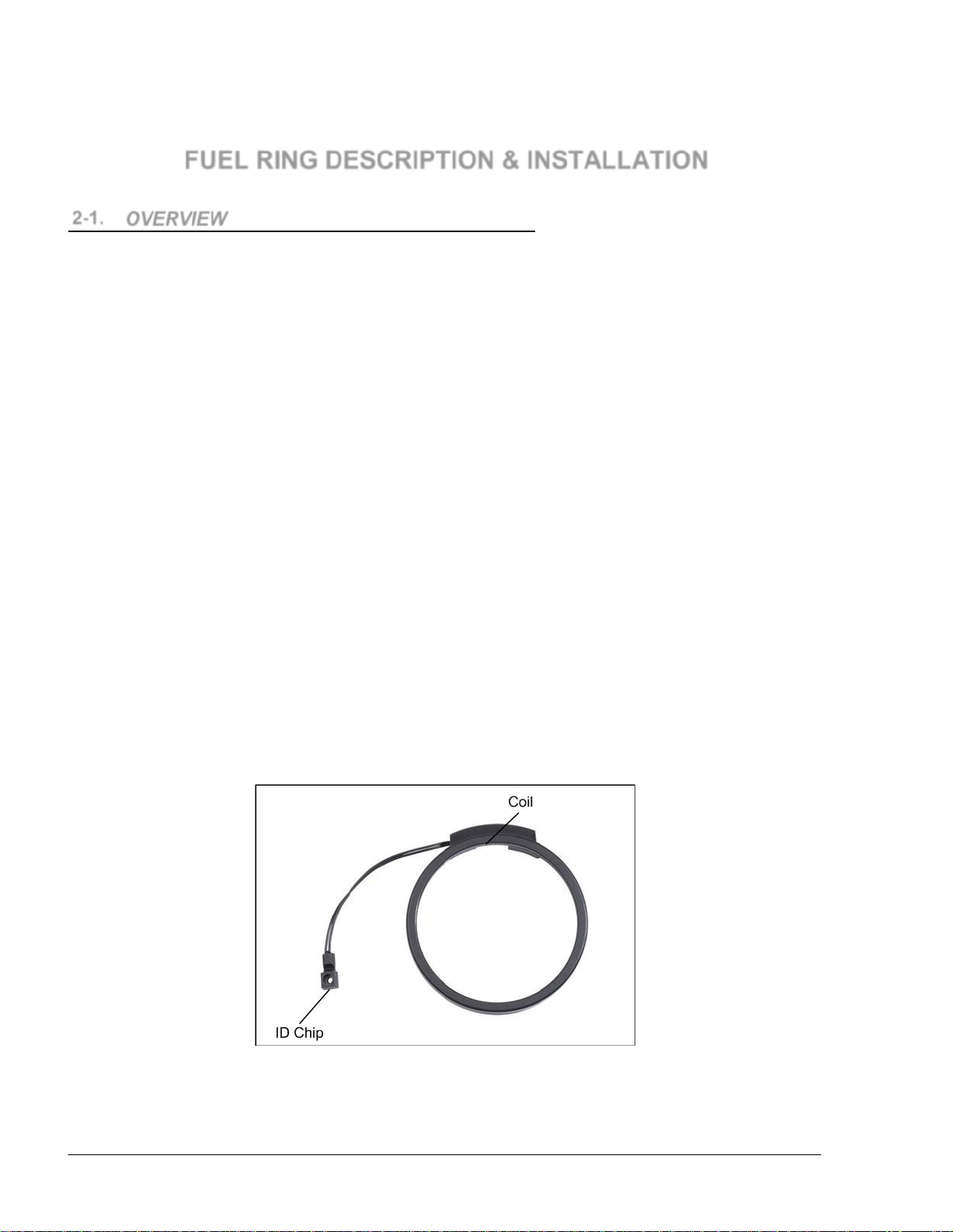
Fuel Ring is a passive vehicle identification tag for refueling (RFID with no internal power sources)
which provides encrypted information on the vehicle identity, corporation or driver identification
and fuel type.
Fuel Ring includes a coil installed around the vehicle's fuel tank inlet and an ID chip. The coil
receives the transmission from the Wireless Nozzle Reader and transmits the chip information to
the Fuel Point PLUS system.
Fuel Ring features a patented removal protection mechanism to eliminate risk of theft or fraud. The
coil and the chip are connected through a cable, so that the ID chip can be installed either in a
concealed place inside the truck or next to the fuel tank inlet in light vehicles (the distance between
the coil and the ID chip must not exceed 39.37"-1M). Enhanced protection is achieved by
correlating the DataPass and the Fuel Ring of the same vehicle
The following section describes two types of installation procedures:
2-1.1. Fuel Ring Main Components
The Fuel Ring comprises two major parts as follows:
A coil (a uniquely designed coil for Fuel Point PLUS vehicle installations)
A one-time programmed ID chip housed in a casting package, protecting the unit from
Installation on private vehicles (see paragraph 2-5)
Installation on heavy vehicles (see paragraph 2-6)
mechanical damage.
Figure 2-1. Fuel Ring Components
Page 17
Fuel Point PLUS Vehicle Installation and Configuration Manual
17
2-2. TYPICAL INSTALLATION KITS
815801001
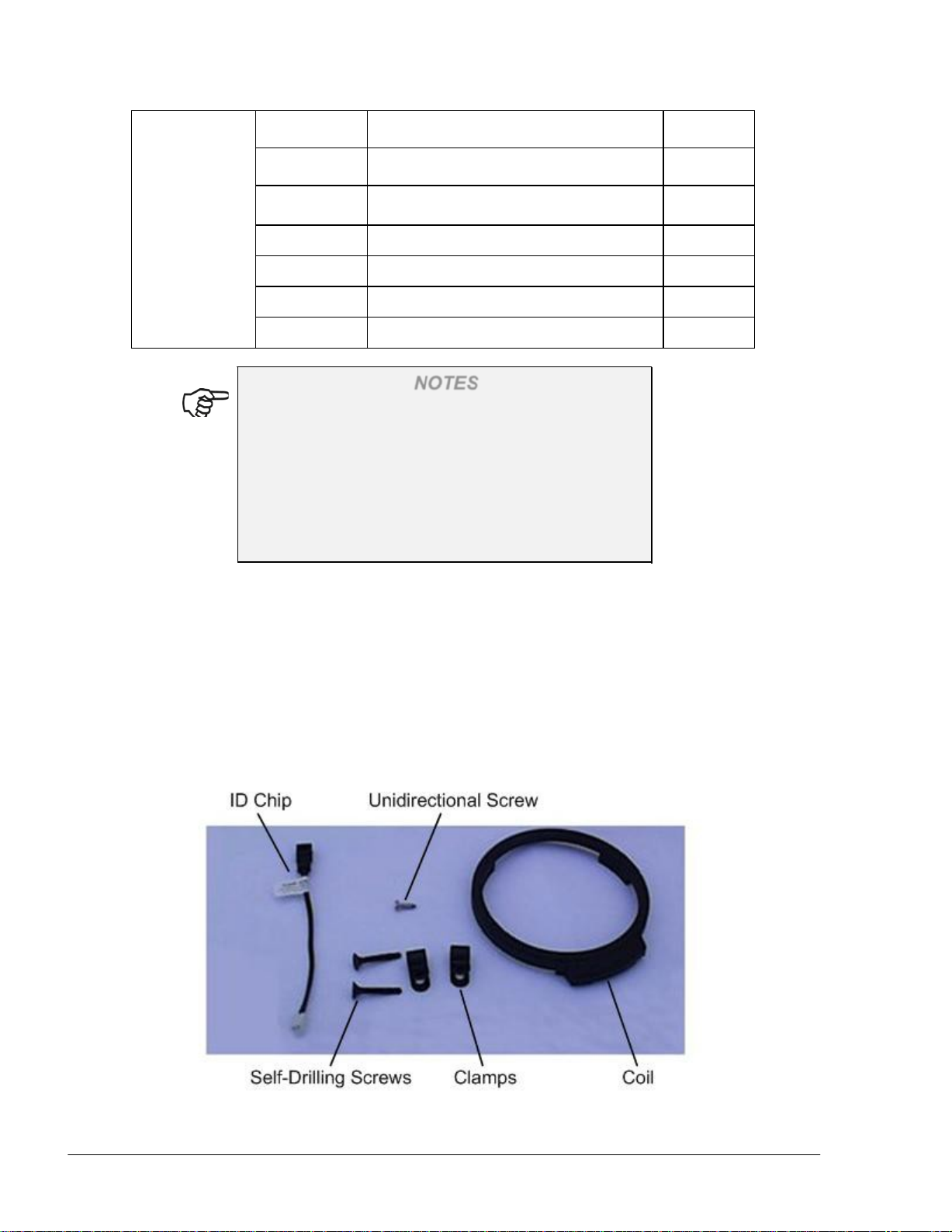
Table 2-1 and Table 2-2 show a typical kit description (see also Figure 2-2, Figure 2-3). Note that
the ID chip and the Fuel Ring coil are separate components and do not form part of the light or
heavy vehicle kits.
NOTES
1. Each item in the Fuel Ring kit has a minimum
ordering quantity. Please refer to Gasboy's
marketing personnel for ordering information.
2. Certain items (e.g. glue, Glue Accelerator,
Adhesive) are not supplied and must be
purchased by the customer as they are required
for installation
3. Programming/configuring the Fuel Ring with the
WP must be performed prior to installation, due
to safety requirements.
Table 2-1. Light Vehicle - Kit Description
Kit P/N P/N Description Packs
Qty.
M09678B008 100 Fuel Ring Installation Kit for Light Vehicles, without
glue
815202401 Screw, self drilling, 6x1"flat, 100 pcs 2
815206001 Screw, one-way, 100pcs, 2.9x9.5mm 1
("¼) Cable clamp, black,100 pcs 2
Table 2-2. Heavy Vehicle - Kit Description
Kit P/N P/N Description Packs
M09678B009
100 Fuel Ring Installation Kit for Heavy Vehicles, without
glue
814905500 Fuel Ring security cover 100
Qty.
Page 18
Fuel Point PLUS Vehicle Installation and Configuration Manual
18
815202401 Screw, self drilling, 6x1"flat, 100 pcs 2
815206900 Screw, security bolt, M8x20 100
815305500
Washer, flat,
M8/EXT=20mm/1 2mm
815801001 ("¼) Cable clamp, black,100 pcs 2
815805802 Nirosta wire, 25pcs 2
815806001 Clamp-coil holder, 100 pcs 3
815806400 Band, Lok-Tie BL213, 7.9x482mm 50
NOTES
1. For cases where fuel inlet neck is short, use the
provided stainless wire; otherwise use the clamp
band
2. If the coil/ID chip cannot be secured using
wires/clamp bands/screws, use Super Glue and a
fast activation accelerator. Cover the device with
a dual component adhesive (such as Epoxy).
The following adhesive substances are recommended for use:
1. SuperGlue, Cyanoacrylate- CA01, HOLDTITE
100
2. Glue, Acrylic, ST3294, high VEL. Black, HOLDTITE
3. Surface cleaning solution
4. Activator, pronto, 60ml (3M)
Figure 2-2. Light Vehicle Typical Installation Kit Components
Page 19
Fuel Point PLUS Vehicle Installation and Configuration Manual
19
M09678B006
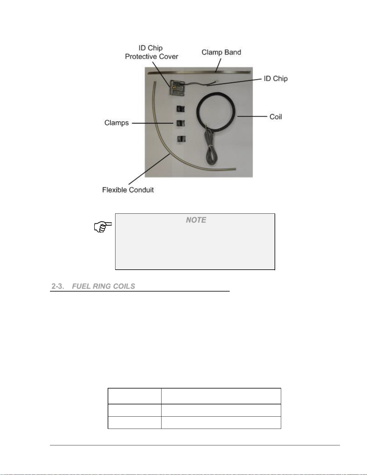
Figure 2-3. Heavy Vehicle Kit Description
To extend SuperGlue and accelerator shelf life, store
the products at a temperature of 200 C or less. High
temperature conditions or direct sunlight reduces
shelf life dramatically. For more details refer to
manufacturer's instructions.
2-3. FUEL RING COILS
The following Fuel Ring coils are available to fit a wide range of fuel inlets:
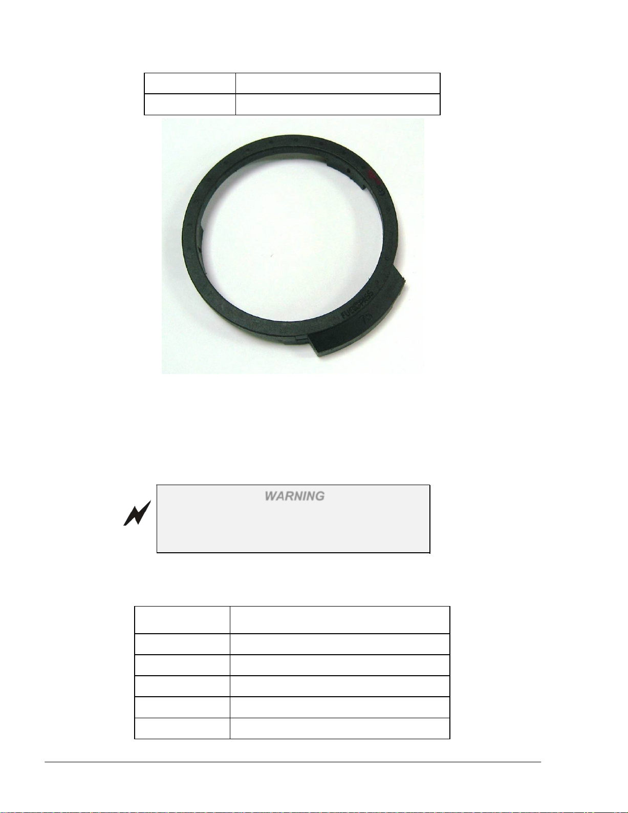
2-3.1. Shaped Coil
Designed to maintain a distance from metal surfaces, the Shaped coil (see Figure 2-4, Table 2-3)
includes an ID chip connector and three support legs which can be easily glued.
Intended for use in cases where an easy connection to the ID chip is required, mainly when the chip
is close to the Wireless Nozzle Reader, e.g. private vehicles.
The Shaped coil is connected to the ID chip by plugging the chip's connector to the coil's connector.
Table 2-3. Shaped Fuel Rings
NOTE
Part Number
M09678B005
Shaped, 2.95"
Shaped,3.34"
Description
Page 20
Fuel Point PLUS Vehicle Installation and Configuration Manual
20
M09678B007
M09680B020
Shaped, 3.74"
ID chip
Figure 2-4. Fuel Ring Shaped Coil
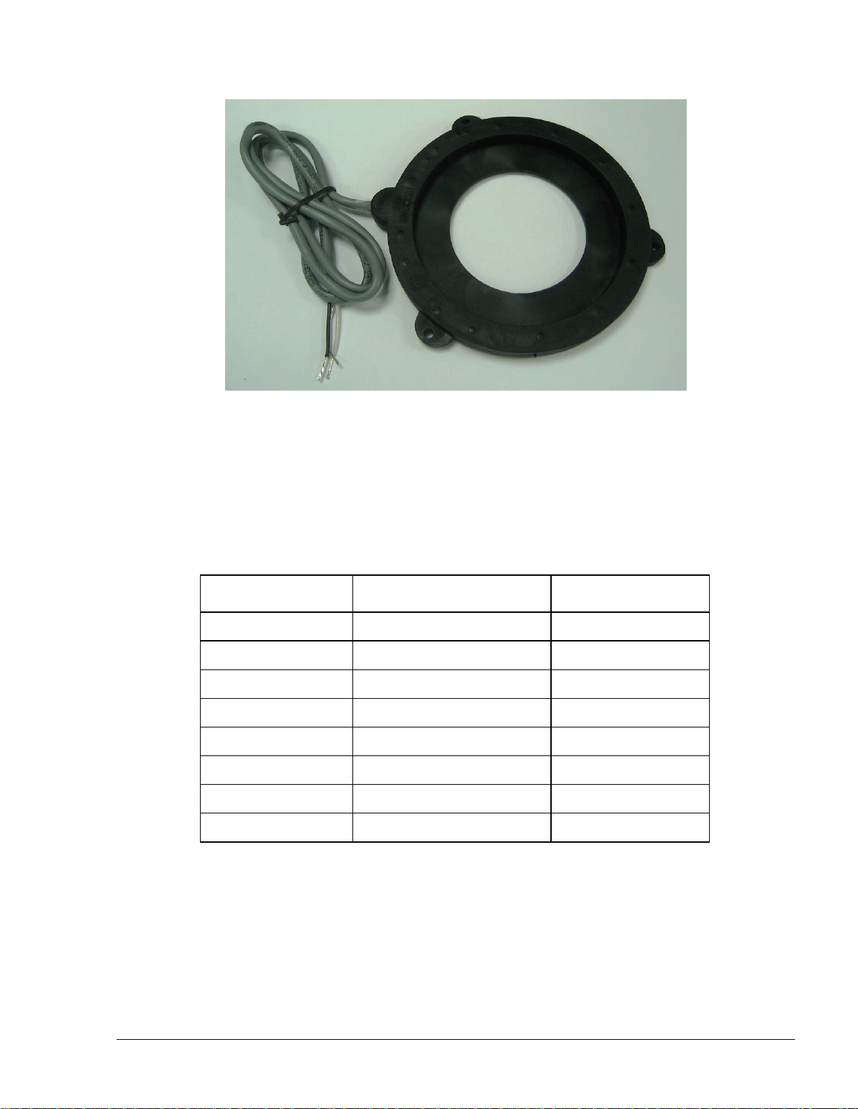
2-3.2. Self Installed Coil
The Self Installed coil (see Figure 2-5, Table 2-4) is rubber coated and includes an internal rubber
ring designed for installation in heavy or light vehicles having short fuel inlet necks.
The Self Install coil should not be used in tanks
made of Aluminum. Use supporting legs to keep it
up off the surface.
The ID chip connector should be cut, in order to be connected to the coil's wires.
Table 2-4. Self-Installed Fuel Rings
Part Number
M09678B001 Self-installed, 2.75"
M09678B002 Self -installed, 4.13"
WARNING
Description
M09678B003 Self-installed, 4.72"
M09678B004 Self-installed, 5.11"
M09680B020 ID chip
Page 21
Fuel Point PLUS Vehicle Installation and Configuration Manual
21
Figure 2-5. Fuel Ring Self Installed Coil
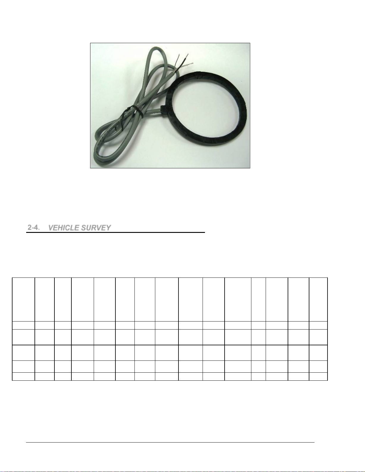
2-3.3. Molded Coil
Widely used, the Molded coil (see Figure 2-6, Table 2-5) is ~7mm thick and can slightly change its
shape.
Table 2-5. Molded Fuel Ring
Part Number
Description
Notes
M09678B010 Molded coil, 2.165" Cable length: 100cm
M09678B011 Molded coil, 3.15"
M09678B012 Molded coil, 3.54"
M09678B013 Molded coil, 3.74"
M09678B014 Molded coil, 4.33"
M09678B015 Molded coil, 4.72" For heavy vehicles
M09678B016 Molded coil, 5.11" For heavy vehicles
M09678B017 Molded coil, 5.71" For heavy vehicles
Page 22
Fuel Point PLUS Vehicle Installation and Configuration Manual
22
N
of
on
er
d
o
C
VOLVO
S50
2005
80
1 CAN
OBD II
Elect.
12
Germany
5
11
6
nd
9
nd
VPW
85
12
Figure 2-6. Fuel Ring Molded Coil
2-4. VEHICLE SURVEY
Before performing the vehicle installation fill in the following table as shown in Table 2-6 so as to
order to order the relevant equipment for the vehicle (DataPass, µDataPass, adapters, etc.).
Table 2-6. Vehicle Survey – Example
Vehicle
manuf.
Liaz
Mercedes
Ford transit 2003 85
Lada private 1996
Model
25625-
305 2004 75
Year
2005 95
external
diameter
(mm)
Fuel
Inlet/neck
high (mm)
200
250
20
umber
tanks
1
2
1
1
BUS type
ISO9141
K-line
J1850
BUS
Connecti
type
pin, rou
connector
pin, rou
connector
OBD II
Fuel
Inlet
Table 2-7 shows of the most commonly used vehicle plugs:
Odometer
manuf.
Kinzle mechanic
Odomet
type
Elect.
Elect.
Elect.
Mechanical
odometer
connection
thread
1.75" 24
2.25" 24 yes
1.5"
size
Power
12
Articulate
us yes / n
omments
bus
bus
Origin
Russia
Germany
UK
Russia
Page 23
Fuel Point PLUS Vehicle Installation and Configuration Manual
23
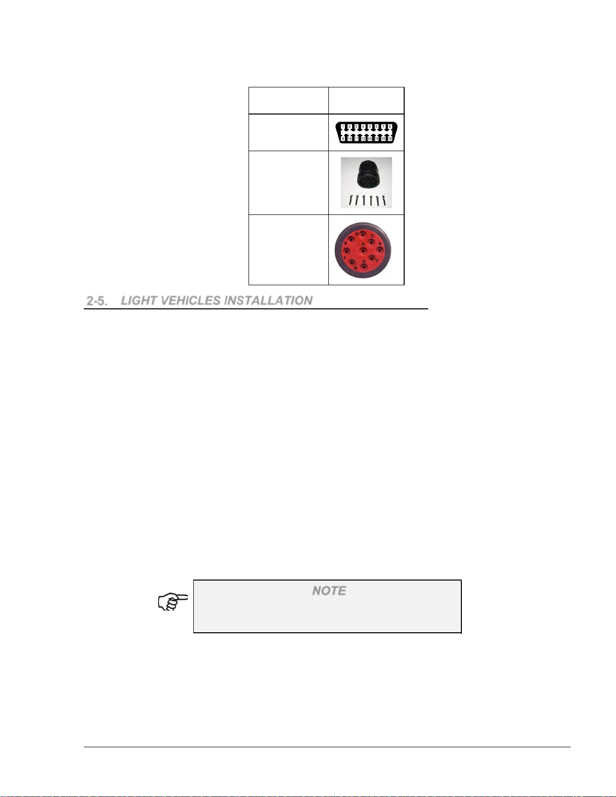
Table 2-7. Common Bus Connectors
Type
Connector
OBD II
6-PIN round
connector
9-PIN round
connector
2-5. LIGHT VEHICLES INSTALLATION
2-5.1. General
Two techniques, or a combination of both, are available for installing the coil unit:
By gluing the coil's bottom surface to the vehicle
By gluing the coil's bottom surface to the vehicle and clamping it
Place the coil unit around the fuel inlet. Pay special attention to the coil's flat part direction –
verify that the bottom legs surface of the plastic molded coil type faces the surface of the
vehicle. In general, it is possible to place the coil in a number of ways; still, it is advisable to
place the coil in the center of the fuel tank inlet to achieve better performance.
The ID chip is installed by gluing it to the vehicle and by securing the unit using a special screw
in order to prevent removal and theft. The chip's installation is performed either in a concealed
place in the luggage compartment, or in a visible place near the fuel tank inlet. When properly
secured against theft, the unit becomes damaged the moment it is pulled away from the vehicle
after installation is completed. It is required to place the ID chip in a less acces
theft and tampering. A distance of up to 100cm between the coil and the ID chip is permitted.
2-5.2. Preliminary Instructions
Warranty does not cover defects or damage caused
by improper installation.
NOTE
In order to prevent possible problems and difficulties during the installation, please verify that:
1. The coil in use is larger than the fuel tank inlet to improve coil assembly
2. The coil is being kept away from metal surfaces, maintaining an air gap of at least 5mm
3. The coil is assembled as close as possible to the Wireless Nozzle Reader coil when the
fueling nozzle is inserted
sible location for
Page 24
Fuel Point PLUS Vehicle Installation and Configuration Manual
24
4. The unit is handled and carefully, avoiding mechanical pressure on the chip. Improper
handling could damage the unit and cause malfunction
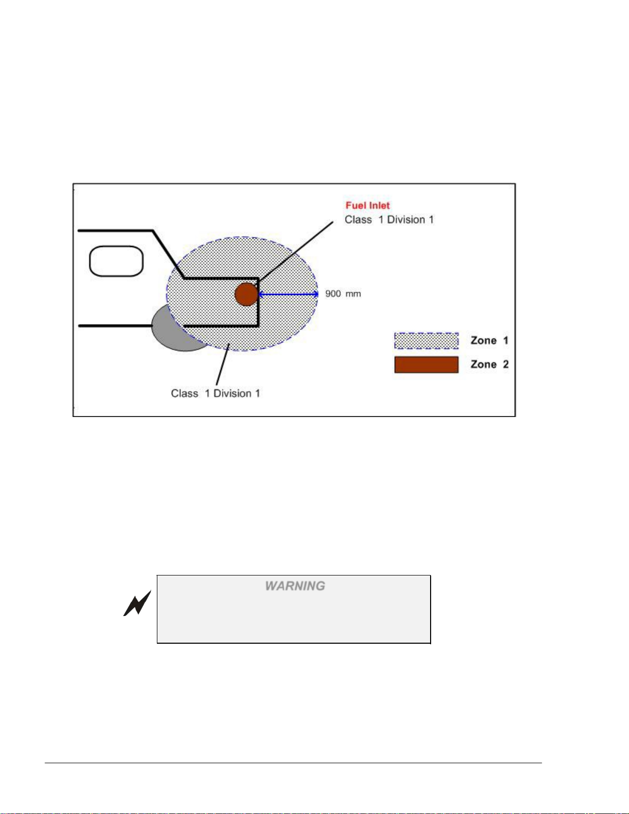
5. The installation area complies with the approved location as shown in Figure 2-7. Please
note that this drawing applies to an open fuel inlet
6. Fuel Ring should only be installed when fuel inlet cover is closed.
Figure 2-7. Typical Installation Approved Location
2-5.3. Required Tools
Cutter
Crimping tool
Pliers
A drilling machine approved for hazardous environment
2-5.4.Installation Procedure
Proceed as follows:
1. Ensure that the fuel tank inlet cover is closed
Before installing or servicing equipment, carefully
observe the warnings and precautions provided at
the beginning of this manual.
2. Use a Fuel Ring of optimal size (refer to Table 2-5) which can be easily placed around
the fuel tank inlet and allows the opening and closing of the fuel tank inlet cover
3. Choose an optimal and secure position for the ID chip. In cases where the installation is
performed near the fuel tank inlet, it is preferable to choose the upper part of the
WARNING
Page 25
Fuel Point PLUS Vehicle Installation and Configuration Manual
25
compartment, at the sides if possible, but not at the bottom, as the fuel nozzle may
damage the ID chip while refueling. The surface must be flat for better gluing and to
ensure that the unit is not damaged by pressure applied during installation
4. Using a soft sandpaper (e.g. #300), slightly sand the area where the ID chip is to be
glued. Pay attention not to damage the car color
5. Clean thoroughly the surface on which the coil and ID chip are to be placed using a
clean cloth and cleaning solution
6. The ID chip is installed with glue with the option of using a special screw, which is also
included in the kit:
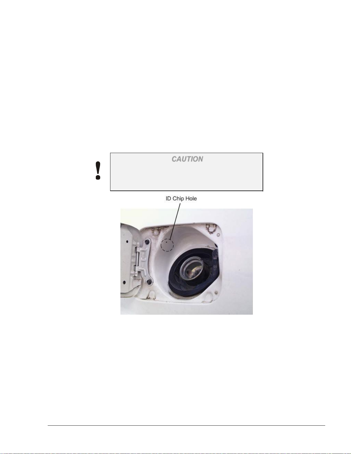
a. In the designated area (see Figure 2-8), drill a 0.094" (2.4 mm) diameter hole. Be
careful not to drill through the fuel tank. Upon drilling completion, make sure to
clean the area before applying the glue
CAUTION
Drilling should be performed by authorized
personnel equipped with a dedicated drilling
machine.
Figure 2-8. ID Chip Preferred Position
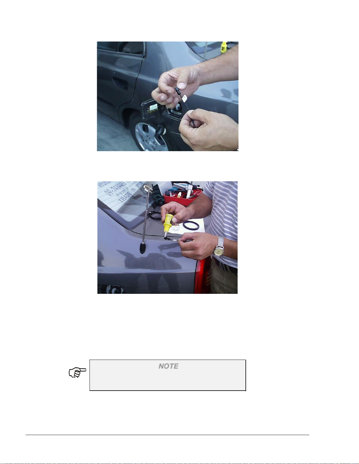
b. Insert the one-way special screw into the ID chip (see Figure 2-9)
Page 26
Fuel Point PLUS Vehicle Installation and Configuration Manual
26
Figure 2-9. Inserting One-Way Screw
c. Apply instant glue to the back part of the ID chip (see Figure 2-10)
Figure 2-10. Applying Adhesive
d. Secure the screw into position in the space prepared, without applying too much
pressure on the screw. Make sure to go through all the instructions in order to
prevent malfunction
e. Spray instant glue accelerator - Activator, pronto, 60ml (3M) around the glued
area
NOTE
When installing the Shaped coil, first connect the ID
chip to the coil.
7. After connecting the coil to the ID chip, to avoid corrosion caused by humidity and
accumulation of fluid at the connection area (shaped coil only), it is recommended to:
seal the connector's area by applying dual component glue DP-805NS (3M), or neutral
silicon on top of the connectors such as Terostat939, or Holdtite HNCS
Page 27
Fuel Point PLUS Vehicle Installation and Configuration Manual
27
8. To secure the coil using clamps:
a. Place two clamps on the coil
b. Place the coil so that the coil support legs face the metal surface and the cable
extending from the coil faces the ID chip
c. Using two self-drilled screws, secure the clamps (see Figure 2-11). Be very
careful not to drill through the fuel tank.
Figure 2-11. Securing the Clamps
To secure the coil using glue:
a. Clean the surface to be glued
b. Apply few drops of Cyanoacrylate adhesive (SuperGlue) to the bottom of the
coil's support legs surface
c. Place the coil so that the coil support legs face the metal surface and the cable
extending from the coil faces the ID chip and hold for several seconds
d. While securing the coil, spray instant glue accelerator around the area.
9. To secure the unit against theft, apply Acrylic, dual-components (epoxy glue) to the
upper and lower part of the chip only as shown in Figure 2-12
Page 28
Fuel Point PLUS Vehicle Installation and Configuration Manual
28
Figure 2-12. Securing the ID Chip
2-5.4.1. Installing the ID Chip inside the Trunk
As aforementioned, to prevent theft and tampering it is highly recommended to install the ID
chip in a concealed place in the luggage compartment. This procedure is also suggested for
vehicles having plastic fuel inlets.
Proceed as follows:
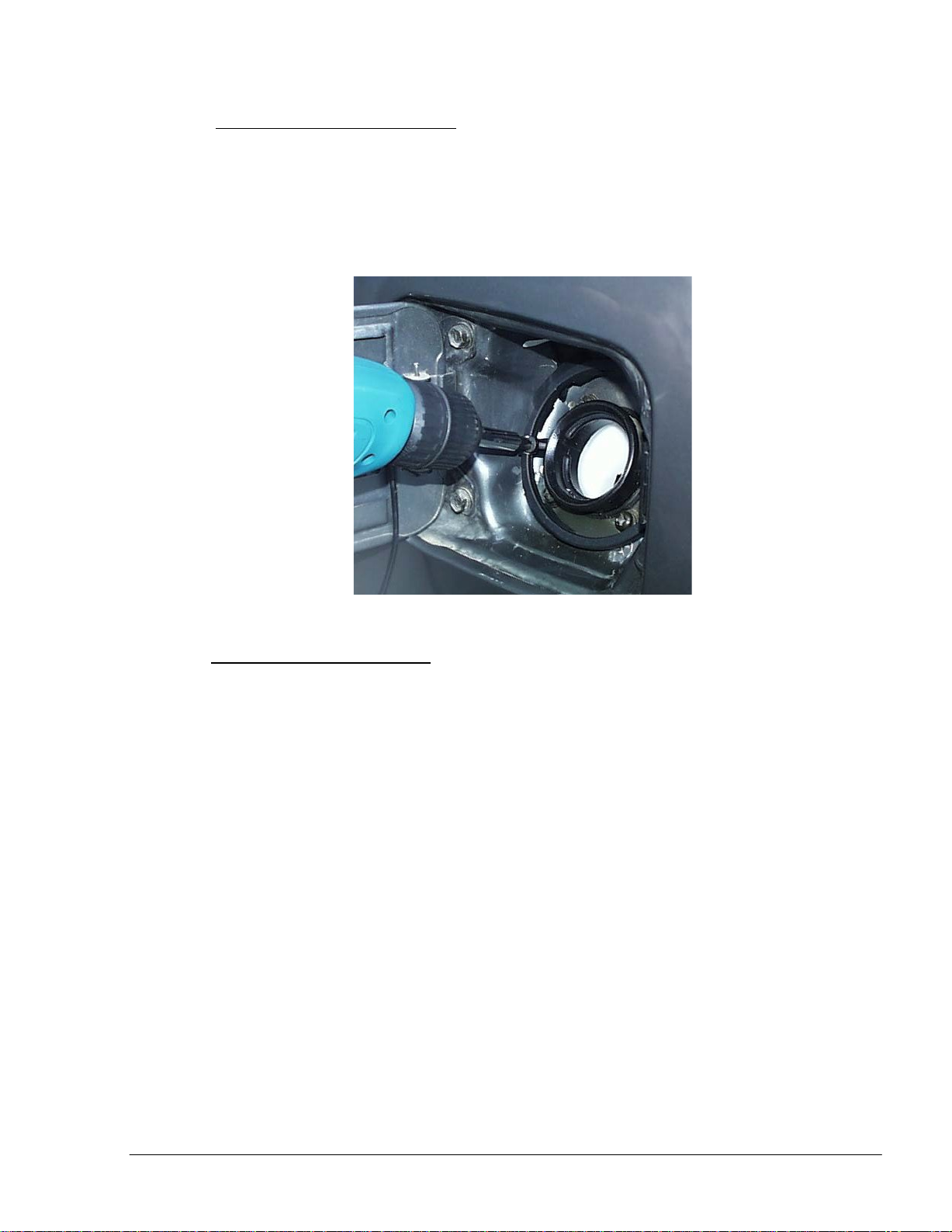
1. Drill a 0.094" (2.5mm) hole inside the trunk near the fuel inlet using a drilling machine
approved for hazardous environment (see Figure 2-13)
Figure 2-13. Drilling the Trunk
2. Clean thoroughly the surface on which the ID chip is to be placed using a clean cloth
and cleaning solution
Page 29
Fuel Point PLUS Vehicle Installation and Configuration Manual
29
3. Apply instant glue to the back part of the ID chip
4. Secure the screw into position in the space prepared, without applying too much
pressure on the screw (see Figure 2-14)
5. Spray instant glue accelerator - Activator, pronto, 60ml (3M) around the glued area
Figure 2-14. Securing the ID Chip
6. Drill a 0.236" (6mm) hole inside the trunk near the fuel inlet and pass the ID chip wires
through the hole
7. Connect the ID chip to the coil's connector and seal the connector's area as described
above
Page 30
Fuel Point PLUS Vehicle Installation and Configuration Manual
30
2-6. HEAVY DUTY VEHICLES INSTALLATION
2-6.1. General
In order to provide a solution for various fuel tank inlets in different truck models, the following
installation configurations are available:
Long Neck Fuel Inlet Installation
Short Neck Fuel Inlet Installation
Self installation
The coil unit is placed around the fuel inlet. Positioning the Fuel Ring as far as possible from the
surface of the truck, achieves better performance. The coil should be installed using Gasboy's
molded Fuel Ring clamps. Those clamps are used to achieve sufficient distance from the fuel tank
inlet and from the fuel tank surface for maximum performance. The ID chip is secured against theft
and is damaged when pulled away from the vehicle after installation is completed.
2-6.2. Preliminary Instructions
Before installing or servicing equipment, carefully
observe the warnings and precautions provided at
the beginning of this manual.
WARNING
NOTE
Warranty does not cover defects or damage caused
by improper installation.
In order to prevent possible problems and difficulties during the installation, please verify that:
1. The coil in use is larger than the fuel tank inlet diameter by approximately 0.984" (25mm)
2. The coil is assembled as close as possible to the inlet cap, without interfering with the
opening and closing of the fuel tank inlet cover
3. In cases where the fuel tank is made of aluminum, a gap of at least 76mm" is maintained
between the coil and the tank and also between the coil and the fuel inlet (larger coil is
recommended)
4. In cases where the Security cover is used, it is positioned as close as possible to the fuel inlet
and to a side wall to prevent rotation or any movement which could damage the ID chip or
the wiring
5. The coil cable is protected from harsh environment by a metal conduit
6. The ID chip is placed in a less accessible location for prevention of theft and tampering
7. The ID chip is not secured to the fuel tank. The Fuel Ring cable is long enough to allow
placing the ID chip in a safe and hidden place inside the truck (a distance of up to 100cm
between the coil and the ID chip is permitted)
Page 31

Fuel Point PLUS Vehicle Installation and Configuration Manual
31
8. The unit is handled and carefully, avoiding mechanical pressure on the chip. Improper
handling could damage the unit and cause malfunction
9. In long neck installations, an additional metal band is tied under the installed coil to prevent
the coil from sliding down and guarantee extra safety.
2-6.3. Required Tools
Cutter
Crimping tool
Pliers
Isolation tape
0.5" (13mm) wrench key
Soldering iron
Soldering tin
CV joint banding tool and cuter (see Figure 2-15)
2-6.4.Coil Installation
2-6.4.1. Long Neck Fuel Inlet Installation Procedure
This installation method is implemented in fuel tanks where the fuel tank inlet protrudes sufficiently
from the fuel tank surface. It makes use of vertical positioning of the molded coil clamps.
Proceed as follows:
1. Place an adequate number of clamps evenly around the coil (use three to five clamps per
coil size). Make sure that the clamps are positioned vertically (see Figure 2-16)
Figure 2-15. CV Joint Banding Tool and Cutter
Page 32

Fuel Point PLUS Vehicle Installation and Configuration Manual
32
Figure 2-16. Positioning the Clamps
2. Remove the fuel inlet cover
3. Tighten the clamps to the fuel tank inlet using the stainless steel clamp band: insert the
clamp band into the designated slots of the clamps. Fasten the metal band firmly to
avoid future sliding of the Fuel Ring using the joint banding tool and cuter (see
Figure 2-17)
Before tightening the metal band, raise the coil as
much as possible to bring it close to the fuel inlet
(less than 3cm) and verify that the coil does not
interfere with the opening and closing of the fuel
tank inlet cover.
NOTE
Page 33

Fuel Point PLUS Vehicle Installation and Configuration Manual
33
Figure 2-17. Tightening the Clamps
4. Lock and tighten it and then cut the edges using the CV Joint Banding Tool and cutter
5. Using a drilling machine or pliers, insert the provided conduit termination nipples at
each side of the flexible conduit
6. Thread the coil wire through the flexible conduit
7. Verify that the cover can be properly closed upon completion of the installation.
Then close the fuel inlet cover. (see Figure 2-18)
Figure 2-18. Complete Coil Installation on Long Neck Inlet
2-6.4.2. Short Neck Fuel Inlet Installation
This installation is implemented in fuel tanks where the fuel tank inlet does not protrude sufficiently
from the fuel tank surface. This installation method makes use of horizontal positioning of the
molded coil clamps.
Proceed as follows:
1. Use a Fuel Ring of optimal size which can be easily placed around the fuel tank inlet and
allows the opening and closing of the fuel tank inlet cover (use a coil larger than the fuel
tank inlet diameter by approximately 35 mm)
2. Insert a metal wire into the molded clamps in the designated slots. Use adequate number
of clamps to position the coil firmly around the fuel tank inlet (use three to five clamps
per coil size). Make sure to position the clamps horizontally as shown in Figure 2-19
Page 34

Fuel Point PLUS Vehicle Installation and Configuration Manual
34
Figure 2-19. Securing Clamps on Short Neck Inlet
3. Using the pistol grip (or pliers), pull the metal wire and twist it until the molded coil
clamps are firmly fastened to the truck's fuel tank inlet. Please note that fastening the
metal wire too strongly may tear the molded coil clamps or wire, while fastening it too
weakly may cause the coil to slide
Before tightening the metal band, raise the coil as
much as possible to bring it close to the fuel inlet
(less than 30mm) and verify that the coil does not
interfere with the opening and closing of the fuel
tank inlet cover.
4. After tightening the metal wire, cut the redundant part of the wire using a cutter.
5. Insert the coil into the molded clamps as shown in Figure 2-20
NOTE
Page 35

Fuel Point PLUS Vehicle Installation and Configuration Manual
35
2-6.4.3. Self Installation
Self installation is performed where both long neck and short neck fuel inlet installations cannot be
performed. The coil is equipped with a rubber membrane, which attaches the coil firmly to the fuel
tank inlet using pressure.
Figure 2-20. Complete Coil Installation on Short Neck Inlet
Proceed as follows:
1. Use a Fuel Ring of optimal size which can be easily placed around the fuel tank inlet and
allows the opening and closing of the fuel tank inlet cover (use a coil larger than the fuel
tank inlet diameter by approximately 25 mm)
NOTE
Raise the coil as much as possible to bring it close to
the fuel inlet (less than 30mm), and verify that the
coil does not interfere with the opening and closing
of the fuel tank inlet cover.
2. Install a metal band around the fuel tank inlet and underneath the coil. to prevent the coil
from sliding down
3. Install the coil on the fuel tank inlet applying pressure (see Figure 2-21)
Figure 2-21. Complete Coil Self – Installation
2-6.5.Chip Installation
2-6.5.1. Installing the Chip with a Security Cover
In order to install the ID chip using a Security cover, proceed as follows:
1. Close the fuel inlet cover
2. Choose an optimal and secure position for the Security cover
Page 36

Fuel Point PLUS Vehicle Installation and Configuration Manual
36
3. Connect the ID chip wires to the coil wires after cutting the chip’s connector by
soldering them or using connection terminals (Conn end. Wire ETC EC-2), or any other
suitable connection
4. Verify that the ID chip is programmed with correct data, using the Wireless Programmer
5. Glue the ID chip inside the Security cover (see Figure 2-22)
Figure 2-22. ID Chip Installed in a Security Cover
6. Attach the security cover to a free hole in the vehicle chassis using the ~0.33" (8mm)
dedicated screw
7. If there are not unoccupied holes, create a ~0.33" (8mm) thread hole using a tap in any
available bar and attach the security cover as shown in Figure 2-23
Figure 2-23. Attaching the Security Cover to a Bar
8. Tighten the screw until its head is broken; the Security cover and the ID chip are now
fully secured and cannot be removed from the vehicle.
Page 37

Fuel Point PLUS Vehicle Installation and Configuration Manual
37
Figure 2-24. Tightening Security Cover
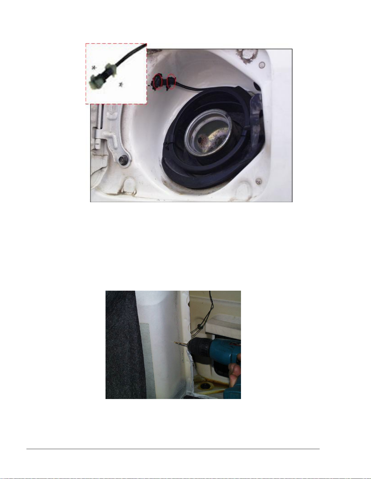
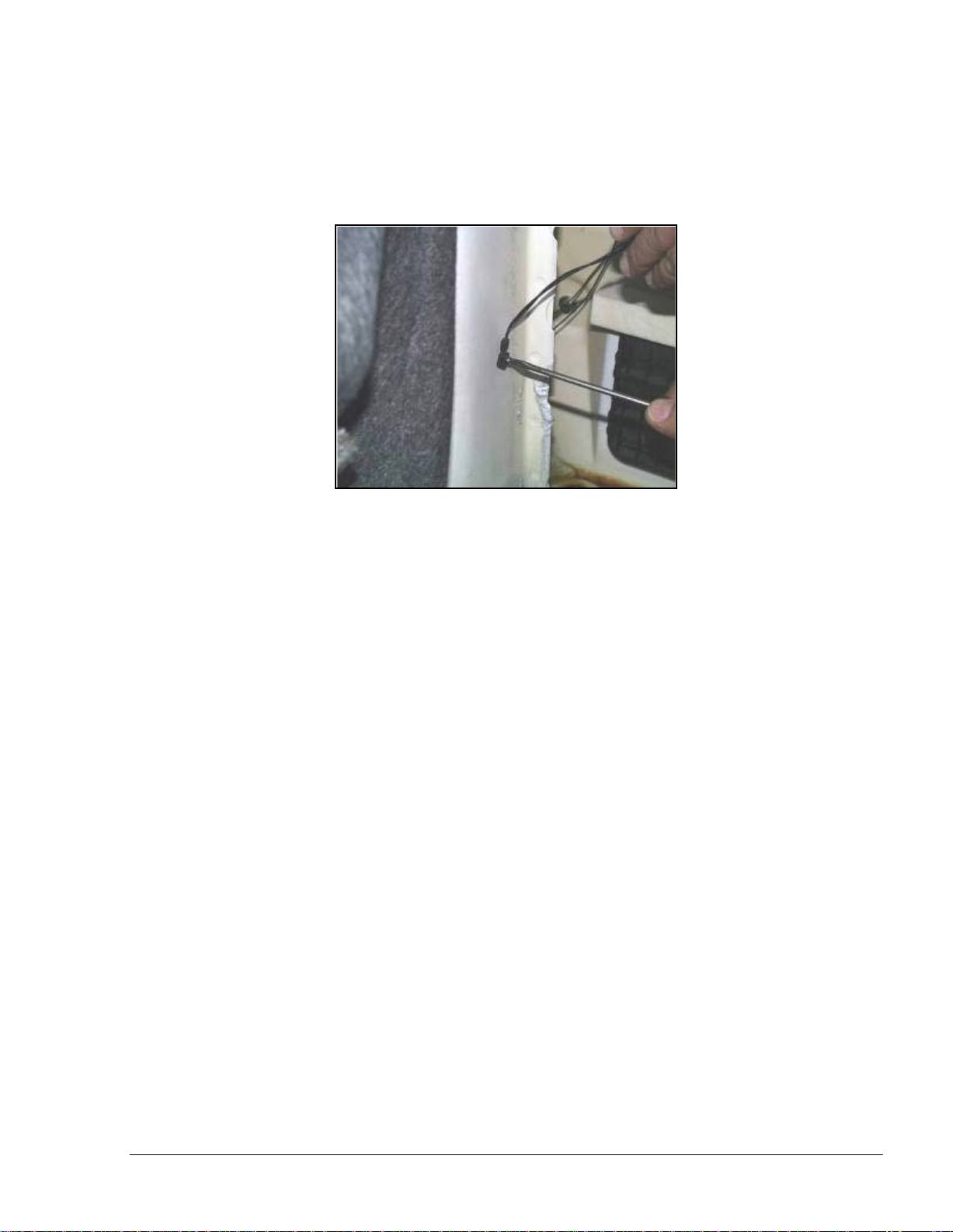
2-6.5.2. Installing the Chip without Security Cover
1. Close the fuel inlet cap
2. Choose an optimal, secure and flat position for the ID chip
3. In the designated area, drill a 0.94" (2.4mm) diameter hole. Do not drill through the fuel
tank! Upon drilling completion, clean the area before applying the glue
4. When installing any coil other than the Shaped coil, connect the ID chip wires to the coil
wires after cutting the chip’s connector by soldering them or using connection terminals
(Conn end. Wire ETC EC-2), or any other suitable connection
5. Verify that the ID chip is programmed with correct data, using the Wireless Programmer
Screw the unidirectional screw through the ID chip in the space prepared. Carefully push
the ID chip towards the vehicle's surface. Don’t tighten the screw firmly; verify that the
chip has a certain amount of freedom and can slightly rotate
6. Tighten the coil-ID chip wires to a fixed object, so as not to interfere with the refueling
process.
Page 38

Fuel Point PLUS Vehicle Installation and Configuration Manual
38
SECTION 3
DATAPASS &
µDATAPASS DESCRIPTION &
INSTALLATION
3-1. OVERVIEW
DataPass is a miniature unit that connects to the vehicle bus and captures data from the vehicle
CPU/BUS. The data is transmitted to the nearest Wireless Gateway Terminal (WGT) in the
forecourt.
The following types are available:
µDataPass / µDataPass+: plugs into the vehicle diagnostic connector (OBD), intended for
light and commercial vehicles
DataPass / DataPass+: connected to the vehicle bus and used in light vehicles, heavy
vehicles and trucks
Table 3-1 enumerates the types of DataPass units available for heavy and light vehicles and the
compatible vehicle interfaces. The device type is recognized by the Wireless Programmer, as
well as by the WGT and OrData system.
Table 3-1. DP Types
Name DP Type Vehicle Interfaces
DP for Heavy Vehicles
DP Heavy
J1587, J1939, FMS, Pulses
vehicle
DP+ for Heavy Vehicles
DP Heavy
J1587, J1939, FMS, Pulses
vehicle
DP for Light Vehicles
DP Light
vehicle
µDataPass CAN Bus
µDataPass+ CAN Bus
µDataPass k-line
µDataPass+ k-line
µDP CAN OBD II CAN
µDP CAN OBD II CAN
µDP K-Line OBD II K Line
µDP K-Line OBD II K Line
OBD II CAN, OBD II K
Line, Pulses
3-1.1. Vehicle Data Provided
The basic DataPass and µDataPass units collect Odometer and Engine Hour information from the
vehicle and it is sent through the WGT network to the FHO for the fleet manager to use.
Page 39

Fuel Point PLUS Vehicle Installation and Configuration Manual
39
The DataPass Plus and µDataPass Plus vehicle units collect on top of Odometer and Engine Hour,
is
n
nts
additional information from the vehicle, enabling the Fleet Managers to get an updated picture on
the vehicles' current status. Table 3-2 describes all vehicle parameters which may be collected and
reported by DataPass Plus devices.
Table 3-2. DataPass Plus Vehicle Parameters
Parameter
Description
Odometer The odometer reading from the vehicle
Main Engine Hour Number of engine hours of the vehicle's main engine
Error Codes On-Board Diagnostics error codes
Aux#1 E.H. Engine Hours of the utility engine which may be
connected to vehicle bus or to DataPass physical line
#1
Aux#2 E.H. Engine Hours of the utility engine which may be
connected to vehicle bus or to DataPass physical line
#2
PTO Power take-off operating hours
Idle Time Idle time counter starts whenever the vehicle's engine
running while the speed is zero for a period longer tha
the threshold defined for the vehicle. Number of eve
and accumulated idle time are both provided
Over Speeding Accumulated time that the vehicle was driven over the
speed threshold set for the vehicle
Over RPM Number of events in which the vehicle crossed the set
RPM threshold
Fuel Level Fuel volume reading at the time of data downloading
(when vehicle enters the WGT network)
Fuel Consumed Total amount of fuel the vehicle consumed (from day
one)
3-1.2. Availability of Vehicle Data according to Vehicle Interface Type
Table 3-3 enumerates the list of data parameters that can be supported by each of the vehicle
interface types. The various DataPass types can provide parameters according to their availability in
the various interfaces.
Table 3-3. Availability of Vehicle Data according to DataPass and Interface Type
DP+ Heavy μDP+ μDP+ DP Heavy μDP μDP
Page 40

Fuel Point PLUS Vehicle Installation and Configuration Manual
40
Int. Type/
Data Item
1587 1939 FMS PLS CAN K J1587 J1939 FMS PLS CAN K
Odometer + + + + + + + + + + + +
Error
Codes
Main
E.H.
+ + + - + + - - - - - -
+ + + + + + + + + + + +
Aux1 E.H + + + - - - - - - - - -
Aux2 E.H + + + - - - - - - - - -
PTO
Timer
+ + + - - - - - - - - -
Idle Time + + + - + + - - - - - -
Fuel
Consumed
Fuel
Level
Over
speeding
Over
RPM
+ + + - - - - - - - - -
+ + + - + + - - - - - -
+ + + - + + - - - - - -
+ + + - + - - - - - - -
Availability of parameters may vary from vehicle to
vehicle, since a parameter defined in the interface
protocol may be actually not provided by the
vehicle.
3-2. DATAPASS DESCRIPTION
DataPass and is used in heavy and light vehicles and supports most common bus protocols.
The following units are available:
DataPass for light vehicles P/N M09693B004 (see Figure 3-1)
NOTE
Page 41

Fuel Point PLUS Vehicle Installation and Configuration Manual
41
DataPass + for heavy vehicles, P/N M09693B001
Figure 3-1. DataPass for Light Vehicles (OBD-II)
Figure 3-2. DataPass (J1708/FMS) for Heavy Vehicles
The DataPass is installed using the provided DataPass harness (see Figure 3-3). The harness is
installed inside the driver cabin, behind the dashboard and connects to the vehicle's diagnostics
connector in light vehicles, or to the diagnostics plug rear wiring in heavy vehicles.
Page 42

Fuel Point PLUS Vehicle Installation and Configuration Manual
42
Figure 3-3. DataPass Harness
3-2.1. Technical Specifications
Table 3-4 lists the specifications for the DataPass units.
Table 3-4. DataPass Specifications
Parameter Value
Height 15 mm
Width 70 mm
Physical
Depth 21 mm
Weight 45g
Connectors 562810 Molex
Supply voltage Normal operation: 12VDC
(Nominal)
Minimum: 10 VDC
Maximum: 32 VDC
Current
consumption
Electrical
(typical)
Temperature
Environmental
Conditions
Range
Humidity 95% non-condensing
KLINE Mode:
Sleep mode: 5mA
Active mode: 35mA
CAN Mode:
Sleep mode: 5mA
Active mode: 25mA
J1708 Mode:
Sleep mode: 5mA
Active mode: 25mA
Operating: -40 to +70 ºC
Storage: -40 to +85 ºC
Page 43

Fuel Point PLUS Vehicle Installation and Configuration Manual
43
Parameter Value
Wireless
Interfaces
Single IEEE802.15.4 wireless
channel
Operating Frequency:
ISM 2.405 to 2.480 GHz
(Global license free band)
Implements proprietary mesh
network
IEEE802.15.4
Modem
DSSS/FA – Direct Sequence
Spread Spectrum with
Frequency Agility
Supported network topologies:
Propriety mesh network
Channel capacity:
Communication
Wireless Antenna Built in PCB Antenna
Wired Interfaces OBDII – J2284/ISO15765 (CAN
16 frequency channels /
5MHz channel spacing
Transmit power output:
2mW (3dbm)
Receive sensitivity:
-101dbm
BUS)
Data rate: 250Kbps / 500Kbps
OBDII – ISO14230/ISO9141
(KLINE)
Data rate: 10400bps
J1708/J1587
Data rate: 9600bps
3-2.2. DataPass Pinout
Table 3-5 details the DataPass connector pinout.
Table 3-5. DataPass Pinout
Pin # Pin Name Description
10 VIN- Supplied voltage (–)
9 VIN+ Supplied voltage (+)
Page 44

Fuel Point PLUS Vehicle Installation and Configuration Manual
44
PULSES
interface is selected (via the WP)
8 K LINE Utilized for K- line protocol
7 Rx Used for diagnostics
6 Tx Used for diagnostics
5 ODO
Pulses representing mileage from vehicle; use when PLS
4 VPW For future use
3 BUS L For CanBus protocol, connect to 'CAN L' in the vehicle bus
(OBD-II DataPass type only)
For J1708 protocol, connect to 'Line A' in the vehicle bus
(J1708 DataPass type only). For J1939 protocol, connect to
CAN L to DP pin 3
2 BUS H For CanBus protocol, connect to 'CAN H' in the vehicle bus
(OBD-II DataPass type only)
For J1708 protocol, connect to 'Line B' in the vehicle bus
(J1708 DataPass type only)
For J1939 protocol, connect to CAN H to DP pin 2
J1939 - communication type protocol utilized in trucks (its
implementation varies from truck manufacturer to the other; it
is recommended to test the DataPass with the relevant vehicle
to ensure it is supported
1 ENG
HOUR*
*Connect pin#1 (blue) to ignition switch, to achieve Sleep mode for the
DataPass, or connect pin#1 to pin#9 (no timeout Sleep mode).
Signal representing engine hours from vehicle; use when PLS
interface is selected (via the WP)
3-3. µDATAPASS DESCRIPTION
Intended for light and commercial vehicles, the µDataPass is a connector shaped unit that plugs into
the light vehicle On Board Diagnostics connector (OBD II).
The following units are available:
μDataPass for CAN Bus protocol, P/N M09693B002 (see Figure 3-4)
μDataPass+ for CAN Bus protocol, P/N M09693B005
μDataPass for K-Line Bus protocol, P/N M09693B003 (see Figure 3-5)
μDataPass + for K-Line Bus protocol, P/N M09693B006
Page 45

Fuel Point PLUS Vehicle Installation and Configuration Manual
45
Figure 3-4. µDataPass for CAN Bus
Figure 3-5. µDataPass for K-Line Bus
Please check the manufacturer specifications for the
proper protocol supported by the vehicle.
3-3.1. Technical Specifications
Table 3-6 lists the specifications for the μDataPass units.
Table 3-6. μDataPass Specifications
Parameter Value
Height 22 mm
Width 70 mm
Physical
Electrical
Depth 17 mm
Weight 10g
Connectors OBDII compatible (male)
Supply voltage Normal operation: 12VDC
NOTE
Page 46

Fuel Point PLUS Vehicle Installation and Configuration Manual
46
(Nominal)
(KLINE)
Parameter Value
Minimum: 10 VDC
Maximum: 32 VDC
Current
consumption
(typical)
KLINE Interface:
Sleep mode: 4mA
Active mode: 35mA
CAN Interface:
Sleep mode: 4mA
Active mode: 25mA
Environmental
Conditions
Temperature
Range
Wireless
Interfaces
Operating: -40 to +70 ºC
Storage: -40 to +85 ºC
Single IEEE802.15.4 wireless
channel
Operating Frequency:
ISM 2.405 to 2.480 GHz
Communication
IEEE802.15.4
Modem
(Global license free band)
Implements proprietary Mesh
network
DSSS/FA – Direct Sequence
Spread Spectrum with
Frequency Agility
Supported network topologies:
Propriety Mesh network
Channel capacity:
16 frequency channels /
5MHz channel spacing
Transmit power output:
2mW (3dbm)
Receive sensitivity:
-101dbm
Wireless Antenna Built in PCB Antenna
Wired Interfaces OBDII – J2284/ISO15765 (CAN
BUS)
Data rate: 250Kbps / 500Kbps
OBDII – ISO14230/ISO9141
Page 47

Fuel Point PLUS Vehicle Installation and Configuration Manual
47
Data rate: 10400bps
Parameter Value
3-3.2. µDataPass Pinout
Table 3-7 details the µDataPass connector pinout:
Table 3-7. µDataPass Pinout
Pin # Pin Name Description
16 VIN+ Supplied voltage (+)
4 VIN- Supplied voltage (-)
7 K-line (ISO) Utilized for K- line protocol
6 CAN H For CanBus protocol, connect to 'CAN
H' in the vehicle bus
14 CAN L For CanBus protocol, connect to 'CAN
L' in the vehicle bus
3-4. TOOLS REQUIRED FOR INSTALLATION
The following tools may be needed for installing the DataPass and μDataPass units:
Star head Screwdriver (TORX)
Flat head Screwdriver
Philips head screwdriver
Cutter
Isolating tape
Soldering iron
Soldering tin
3-5. LIGHT VEHICLES INSTALLATION
3-5.1. Checking Vehicle Protocol
In order to install and use the appropriate µDataPass/DataPass unit, it is necessary to check out the
bus protocol: K-Line or Can bus. The Vehicle Call Monitor unit – VCM (see Figure 3-6) enables
users to find out which OBD-II protocol is supported by the vehicle, for cases where the
manufacturer specifications are not available.
Page 48

Fuel Point PLUS Vehicle Installation and Configuration Manual
48
Proceed as follows:
1. Connect the VCN unit to the OBD-II connector using a DataPass harness (P/N
M09680B051)
2. The appropriated indicator LED is lit (K-Line or CAN)
Figure 3-6. VCM Unit
3-5.2. Installing the μDataPass
The µDataPass installation is a very simple process. However, since µDataPass is a very small
device, it is recommended to fasten the unit to the vehicle using a nylon thread or similar fastener to
prevent loss if removed from the OBD II connector during vehicle servicing.
Proceed as follows:
1. Locate the standard On Board Diagnostics (OBD II, see Figure 3-7) connector (usually
hidden behind one of the panels below the steering wheel, or near the pedals)
2. Remove the panel covering the Diagnostics connector
Figure 3-7. Diagnostics Connector
3. Gently plug the µDataPass into the Diagnostics connector being careful not to bend the
µDataPass pins (see Figure 3-8)
Page 49

Fuel Point PLUS Vehicle Installation and Configuration Manual
49
Figure 3-8. Pluging the μDataPass
4. Tighten the µDataPass in place using a finger (see Figure 3-9)
Figure 3-9. Tightening the μDataPass
5. Re-assemble the board covering the Diagnostics connector.
3-5.3. Installing the DataPass
NOTE
µDataPass installation is the preferred solution for
light vehicles, so the following procedure is rare and
conducted in cases where µDataPass cannot be used.
When access to the rear Diagnostics connector is
problematic, the Adaptor Plug is used (see Para. 3-
5.3.1). In cases where the vehicle Bus cannot be
located, find an Odometer pulses source and connect
to the DataPass.
The DataPass is connected to the Diagnostics connector (see Figure 3-10, Figure 3-11 and
Table 3-8) using the DataPass Harness, exposing the Diagnostics connector's wiring and welding
each of its wires to the corresponding wire in the DataPass Harness as specified in Table 3-8.
Page 50

Fuel Point PLUS Vehicle Installation and Configuration Manual
50
White*
To white wire in VIU
Pulse out to VIU
Yellow**
7
K-line
Green***
6
CAN H
Gray***
14
CAN L
Red****
16
VIN+
Black
4
VIN-
Blue****
16
+POLE
Figure 3-10.OBDII Connector Wiring to DataPass Harness
Table 3-8. Harness OBDII Connections
Short
Harness Wire
OBD-2 Pin
* Do not connect if VIU in exists
** If K-line communication is utilized, do not connect Green & Gray wires
*** If CANBUS communication is utilized, do not connect Yellow wire
**** Short is connected between red and blue wires if engine hour output is not used
Figure 3-11. OBDII Connector Pins Layout
Proceed as follows:
1. Locate the standard On Board Diagnostics (OBD II, see Figure 3-7) connector (usually
hidden behind one of the panels below the steering wheel, or near the pedals)
2. Remove the Diagnostics connector panel (see Figure 3-12)
CAUTION
Confirm the bus protocol in use before proceeding
with the installation. Consult vehicle's technical
specifications if needed.
Description
Page 51

Fuel Point PLUS Vehicle Installation and Configuration Manual
51
Figure 3-12. Removing the Diagnostics Connector Panel
3. Solder DataPass Harness wires to Diagnostics connector wires as in Table 3-8 (see
Figure 3-13)
Figure 3-13. Soldering DataPass Harness to Diagnostics Connector Wires
4. Wrap each soldered wire in insulating tape (see Figure 3-14)
Figure 3-14. Wrapping Connections in Insulating Tape
5. Cut unconnected wires, attach them to the harness and cover with insulating tape (see
Figure 3-15)
Page 52

Fuel Point PLUS Vehicle Installation and Configuration Manual
52
Figure 3-15. Covering Unconnected Wires with Insulating Tape
6. Wrap the newly created harness in insulating tape
7. Connect the DataPass to the harness
8. Fasten the DataPass to any of the vehicle panels/rods using a tie wrap; verify that the
unit does not move (see Figure 3-16)
Figure 3-16. Fastening the DataPass Unit
9. Fasten the newly created harness to any of the vehicle panel/rod; verify that the harness
3-5.3.1. Adaptor Plug
As previously mentioned, the Adaptor plug is used only in cases where it is difficult to access the
connector's rear side.
Perform the following steps:
is well secured
10. Re-assemble the Diagnostics connector panel.
3. Connect the red connector of the adaptor plug to the car's Diagnostics connector (see
Figure 3-17)
Page 53

Fuel Point PLUS Vehicle Installation and Configuration Manual
53
Figure 3-17. Connecting the Adapter Plug
4. Connect the white connector of the adaptor plug to the DataPass connector (see
Figure 3-18)
Figure 3-18. Connecting the DataPass to the Adaptor Plug
5. Fasten the DataPass to the vehicle using a tie wrap; verify that the unit does not move.
3-5.3.2. Installing a Pulse Divider Device
The Pulse Divider (see Figure 3-19) is used in cases where the vehicle's pulse output cannot be read
by the DataPass due to weak signal, too high frequency or vehicle differential signal.
The Pulse Divider receives the inappropriate vehicle signal (Pickup signal), shapes it and/or divides
its frequency to match the signal to the DataPass requirements for reading. Two types of devices are
available:
Pulse Divider (full functionality)
Pulse Divider 4 Digital (limited functionality)
Usually installed behind the dashboard, near the wiring hub of the vehicle, the Pulse Divider can be
connected in three ways: refer to Table 3-9 and Table 3-10 for optional connections and pinout.
Page 54

Fuel Point PLUS Vehicle Installation and Configuration Manual
54
Figure 3-19. Pulse Divider
Table 3-9. Pulse Divider Connections
Signal Type Description Connection Diagram
Option A
Option B
Option C
Input pulses are
above/under zero
level and/or weak
Input pulses are
above zero level
(positive)
Input pulses are
differentia
Page 55

Fuel Point PLUS Vehicle Installation and Configuration Manual
55
Table 3-10. Pulse Divider Pinout
Pin# Wire Color Name Description
1 RED DC INPUT Input voltage from vehicle to Pulse Divider
(10-28VDC)
2 BLACK GROUND Vehicle ground
3 BROWN SIGNAL IN 1 Input pulses from vehicle to Pulse Divider
4 GREEN SIGNAL IN 2 Input pulses from vehicle to Pulse Divider
(when input signal is differential).
Threshold voltage applied to Pulse Divider
when Input pulses are other than differential
5 ORANGE DC OUT N/A
6 GRAY REF/V OUT 1.4VDC reference voltage connected to the
green wire only in cases where Option B is
utilized (otherwise unused)
7 VIOLET :2 OUT Output signal divided by 2
8 YELLOW :4 OUT Output signal divided by 4
9 BLUE :8 OUT Output signal divided by 8
10 WHITE :16 OUT Output signal divided by 16
Page 56

Fuel Point PLUS Vehicle Installation and Configuration Manual
56
3-6. HEAVY VEHICLES INSTALLATION
Pulse
output
Notes
PIN #4 is an alternative in cases
where C3 is available
VDO Kienzle Type – 1314
C3
VDO Kienzle Type – 1315
Z4
D3 / B7 are alternatives in cases
where B8 is available
D3 / B7 are alternatives in cases
where B8 is available
VOLVO Motometer
Type EGK100 ,EGK100-01
B8 / B3 are alternatives in cases
where B7 is available
MAZ truck
B7
3-6.1.General
Obtaining Odometer and Engine hours in heavy vehicles can be done in two ways:
Connecting DataPass to odometer pulses output (directly, or via tachograph's pulses output)
Connecting the DataPass to the vehicle bus, which allows retrieving additional information
from the vehicle computer
3-6.2.Connecting the DataPass to Odometer Pulses Source
A simple way to retrieve odometer pulses is from the truck’s tachograph output.
Installation of the DataPass requires disassembling the vehicle's tachograph and accessing its rear
side wiring in order to connect the DataPass harness to the tachograph's wiring.
Table 3-11 depicts
the connections running between the tachograph and the DataPass. There are
common types of tachographs where Pulse output pin number differs from each other; refer to
Table 3-12. to locate the applicable pin number according to tachograph type and model.
Table 3-11. Tachograph – DataPass Harness Connections
DataPass Harness Wire
White
Red
Black
Blue
Table 3-12. Pulse Output Pin in Various Types of Tachographs
Tachograph
Pulse output
VIN+
VIN-
Vehicle switch
Tachograph Types
VDO Kienzle Type – 1310
VDO Kienzle Type – 1318
VDO Kienzle Type – 1319
C3 / #4
B8 / D3 / B7
B8 / D3 / B7
B7 / B8 / B3
Perform the following steps:
Page 57

Fuel Point PLUS Vehicle Installation and Configuration Manual
57
1. Locate the tachograph in the vehicle. Two extraction slots are placed on both sides (see
Figure 3-20)
Figure 3-20. Tachograph Extraction Slots
2. Use the dedicated extraction tool to disassemble the tachograph (see Figure 3-21)
Figure 3-21. Removing the Tachograph
Handle each wire individually until it is fully
connected and isolated to avoid shorts.
3. Access to the wiring on the back part of the tachograph and expose the desired wire (see
Figure 3-22)
NOTE
Page 58

Fuel Point PLUS Vehicle Installation and Configuration Manual
58
Figure 3-22. Tachograph Wiring
4. Connect ands solder each wire to its corresponding wire in the DataPass harness as shown in
Table 3-11.
Figure 3-23. Connecting DataPass Harness to Tachograph Wiring
5. Wrap each soldered wire in insulating tape (see Figure 3-24)
Figure 3-24. Wrapping Connections in Insulating Tape
6. Wrap the newly created harness in insulating tape (see Figure 3-25)
Page 59

Fuel Point PLUS Vehicle Installation and Configuration Manual
59
Figure 3-25. Covering the Harness with Insulating Tape
7. Connect the DataPass to the harness (see Figure 3-26)
Figure 3-26. Connecting the DataPass
8. Fasten the DataPass to any of the vehicle panels/rods using a tie wrap; verify that the unit
does not move
9. Fasten the newly created harness to any of the vehicle panel/rod; verify that the harness is
well secured (see Figure 3-27)
Page 60

Fuel Point PLUS Vehicle Installation and Configuration Manual
60
Figure 3-27. Fastening DataPass and Harness
10. Gently push the tachograph with its harness into place until it is locked (a clicking sound is
heard).
3-6.3.Connecting the DataPass to the Vehicle Bus
Connections to vehicle bus is implemented via the BUS connector (Figure 3-28) usually hidden
behind one of the dashboard panels). Unlike light vehicles that have standard OBD II
connector, heavy vehicles have many different types of connectors and the DataPass is
connected to the connector wires / harness from the interior part of the panel. Table 3-13
depicts the Pin-out referenced to common protocols utilized in the heavy vehicle to present the
required DataPass wiring. Figure 3-29 and Figure 3-30 describe typical J1587 protocol 6/9 pin
harnesses, while Figure 3-31 describes J1939 protocol harness, including the respective pins
description.
Figure 3-28. Typical Bus Connector
Page 61

Fuel Point PLUS Vehicle Installation and Configuration Manual
61
1
Figure 3-29. J1708 (J1587) 6P Harness – DataPass Connection
Figure 3-30. J1708 (J1587) 9P Harness – DataPass Connection
Figure 3-31. J1939 Harness – DataPass Connection
Table 3-13. BUS Connector Typical Pin Out Description
Pin
Number
Protocol:
FMS/J1939/CAN
+V (vehicle switch) +V (vehicle switch)
Protocol:
J1708/J1587
Page 62

Fuel Point PLUS Vehicle Installation and Configuration Manual
62
2
3
9
10
CAN H
CAN L
J1708 (-B)
J1708 (-A)
+V (vehicle battery) +V (vehicle battery)
-V (vehicle battery) -V (vehicle battery)
Page 63

Fuel Point PLUS Vehicle Installation and Configuration Manual
63
SECTION 4
PROGRAMMING VEHICLE
UNITS
4-1. GENERAL
This section provides instructions on the programming sequence of the vehicle units installed in
private and heavy duty vehicles using the Wireless Programmer device as follows:
FR and DP/DP+ for heavy vehicles (see paragraph 4-5)
FR and DP for light vehicles (see paragraph 4-6)
FR and μDP/μDP (see paragraph 0)
In addition, this section describes the Wireless Programmer device and includes instructions for
setting up the WP and registering the device in the FHO server.
NOTE
If an error message is received when programming
FP +DP units, replace the FP unit, and use the
Replace FP option detailed below.
4-2. WIRELESS PROGRAMMER
WARNING
Programming using the WP should be done in safe
area (Non-Hazardous location). Therefore, it should
be done prior to Fuel ring installation.
Vehicle units are programmed on-the-spot using the Wireless Programmer (WP), P/N PA04010000
(see Figure 4-1).
Page 64

Fuel Point PLUS Vehicle Installation and Configuration Manual
64
Figure 4-1. Home Base Solution Wireless Programmer
4-2.1. WP Specifications
Table 4-1 lists the specifications for the Wireless Programmer.
Page 65

Fuel Point PLUS Vehicle Installation and Configuration Manual
65
Table 4-1. Wireless Programmer Specifications
Parameter Value
Height 29 mm
Width 192 mm
Physical
User Interface
Electrical
Environmental
Conditions
Depth 99 mm
Weight 380g
Connectors Terminal Port: DB-9 (Female)
Power Port: DC Jack
Keyboard 48 Keys Keyboard
Display 2x16 Characters LCD
Supply voltage 7.2V, 2000mAh Lithium-ion internal
battery
Battery Charge
12V to 28V DC input
Voltage
Protection Supply voltage reverse polarity protected
Short circuit protected
Battery over charge and full discharge
protected
Temperature
Operating: -20 to +70 ºC
Range
Storage: -40 to +85 ºC
Humidity In accordance with IEC 68-2-30
Wired
Interfaces
Wireless
Interfaces
Comm.
Wireless
Antenna
RFID/VIU Designed for Low Frequency (125 KHz)
External – RS232 Communication Link
Single IEEE802.15.4 wireless channel
Receive sensitivity: -101dbm
Typical Range: 50 meter at open space
Built in PCB Antenna
chip reading
Read distance: Up to 8cm, influenced by
Tag geometry
Page 66

Fuel Point PLUS Vehicle Installation and Configuration Manual
66
4-2.2. Battery Saving and Battery Chargers
The WP includes a battery saving timeout function which alerts the user emitting three consecutive
beeps in cases where the unit has been idle for more than five minutes.
The unit stays on by pressing any key. When turned off, the user is logged out, and the device can
be turned on again by using the ON/OFF button.
The WP is supplied with two types of battery chargers (see Figure 4-2):
AC Adaptor – connected to the mains
DC Adaptor - connected to vehicle's cigarette lighter socket
Figure 4-2. WP Battery Chargers
Page 67

Fuel Point PLUS Vehicle Installation and Configuration Manual
67
4-3. WIRELESS PROGRAMMER REGISTRATION AND CONFIGURATION
Prior to programming the vehicle units, WP device should be registered in the FHO to which the
vehicles to be programmed are attributed.
4-3.1. FHO Installation
For details on FHO installation, please refer to FHO Installation and User Manual, P/N MDE-4821.
After FHO has been completely set up, verify that the Company name (in Administration → Setup
→ General) field is filled (see Figure 4-3)
Figure 4-3. Administration Setup Screen – General Tab
4-3.2. WP Tunnel Installation
The WP Tunnel application is required for WP registration. Proceed as follows:
1. Double click on the WP Tunnel.exe file. The following welcome screen appears (see
Figure 4-4)
Page 68

Fuel Point PLUS Vehicle Installation and Configuration Manual
68
Figure 4-4. WP Tunnel Setup Wizard Welcome Screen
2. Click Next. The License Agreement screen appears (see Figure 4-5)
Figure 4-5. WP Tunnel Setup Wizard License Agreement Screen
3. Click I Agree. The following screen appears (see Figure 4-6)
Page 69

Fuel Point PLUS Vehicle Installation and Configuration Manual
69
Figure 4-6. WP Tunnel Setup Wizard Choose Install Location Screen
4. Click Next to install the files in the default folder, or click Browse to choose another destination
folder and then click Next. The Connection settings screen appears (see Figure 4-7)
Figure 4-7. WP Tunnel Setup Wizard Connection Settings Screen
5. Enter the Head Office IP Address. In the example above, WP Tunnel is installed in FHO PC, so
the local Host IP address (127.0.0.1) is entered
6. Enter the Serial Com port to which the WP device is to be connected. Click Next
Page 70

Fuel Point PLUS Vehicle Installation and Configuration Manual
70
The FTP stores updated vehicle lists required for
WP proper functioning. Default FTP address:
194.90.151.28 should not be changed.
NOTE
7. The installation process is fully automated. The Installing screen displays process messages, as
well as possible error messages. At the end of the process, click Close to exit the Wizard (see
Figure 4-8)
Figure 4-8. WP Tunnel Setup Wizard Installation Complete Screen
8. An icon is created on the desktop.
4-3.3. Establishing WP - HO Communication
In order to establish communication between the WP and the Head Office, proceed as follows:
1. Access the FHO application and click on the Admin navigation button
2. Select the Registration tab. The following screen appears:
Page 71

Fuel Point PLUS Vehicle Installation and Configuration Manual
71
Figure 4-9. Admin Screen – Registration Tab
NOTE
Prior to registering the WP, remove all certificate
errors. For further information, please refer to
Appendix A in FHO Installation and User's Manual,
P/N MDE-4821.
3. Launch the WP Tunnel application by clicking on the icon; the following screen appears
(see Figure 4-10)
Figure 4-10. WP Tunnel Main Screen
4. Connect the WP to the PC using a RS232 serial cable
Page 72

Fuel Point PLUS Vehicle Installation and Configuration Manual
72
5. Turn on the WP; follow the instructions appearing on the WP display, described in
Table 4-2
NOTE
When operating the WP for the first time, enter
factory defaults user name and password: "admin",
the device will prompt the user for a new username
and password.
Table 4-2. WP Upgrade Sequence
Step
1
2
3
4
Display
Description/Action
Enter User ID and press ENTER
Enter password and press ENTER. Press the
BCK key
The System menu is displayed
Use the DOWN arrow key to move the pointer
(>) to the Sys Functions menu and press
ENTER
Press ENTER
5
6
Press SEND
Wait while the PC connects to the FHO.
6. The WP tunnel displays the session details. After the WP is successfully recognized
by the FHO, the application registers the device serial number and the currently
logged user name and sends to the WP the organization's name (company name). A
confirmation message is displayed (see Figure 4-11)
Page 73

Fuel Point PLUS Vehicle Installation and Configuration Manual
73
Figure 4-11. Approving WP Registration
7. Close the WP Tunnel.
The organization name is recorded in the WP memory and the device is now ready for
programming the vehicle units.
The Block button blocks the WP device (selected from the grid) for future use, while the Unblock
button activates previously blocked WP units.
4-3.4. Updating Vehicle List
The Vehicle List contains updated specific calibration data per vehicle model, required for
programming of DP/µDP units. To download the latest vehicle table from Gasboy's FTP server into
the WP, proceed as follows:
1. Connect the WP to the PC using a RS232 serial cable
2. Launch the WP Tunnel application by clicking on the icon
3. Click Import on the menu bar and then select Vehicle List. The application downloads the
updated vehicle table from the FTP server and displays the session details (see Figure 4-12).
This process takes approximately 2 minutes to complete.
Page 74

Fuel Point PLUS Vehicle Installation and Configuration Manual
74
Figure 4-12. WP Tunnel – Vehicle List Update
4. Do not close the WPTunnel application. Turn on the WP; follow the instructions appearing on
the WP display, described in Table 4-3.
Page 75

Fuel Point PLUS Vehicle Installation and Configuration Manual
75
Table 4-3. Vehicle List Update Sequence
Step
1
2
3
Display
Description/Action
Enter User ID and press ENTER
Enter password and press ENTER. Press the
BCK key
The System menu is displayed. Use the DOWN
arrow key to move the pointer (>) to the Services
option and press ENTER
Use the DOWN arrow key to move the pointer
(>) to the Replace Vehicle Table option and
press ENTER.
Note: After loading the WP with the Vehicle
List for the first time, you may check for
updates and download these updates only, by
selecting the Check for Updates option. If a
new list is available "Update Vehicle
Parameters" message is displayed. Otherwise,
the WP displays: "No need for update"
4
Press SEND
5
6
Wait while the WP receives the data
At the end of the process, the following success
message is displayed. Restart the WP
Page 76

Fuel Point PLUS Vehicle Installation and Configuration Manual
76
4-3.5. Local Download
Local Download option allows downloading the latest version of the following components from
Gasboy's FTP into your WP device:
WP AVR (antenna component)
WP ARN (WP application)
DP and µDP firmware
Proceed as follows:
1. Connect the WP to the PC using a RS232 serial cable
2. Launch the WP Tunnel application by clicking on the icon
3. Click Loader on the menu bar and then select Start. The Loader dialog box appears (see
Figure 4-13)
Figure 4-13. WP Tunnel – Vehicle List Update
4. Select the component radio button in the Download options section and then click Select File
and Start
5. A file selection dialog box appears. Browse for the file and click OK
6. Click Select File and Start
7. Do not close the WPTunnel application. Turn on the WP; follow the instructions appearing on
the WP display, described in Table 4-4.
Page 77

Fuel Point PLUS Vehicle Installation and Configuration Manual
77
Table 4-4. Local Download Sequence
Step
1
2
3
4
Display
Description/Action
Enter User ID and press ENTER
Enter password and press ENTER. Press the
BCK key
The System menu is displayed. Use the DOWN
arrow key to move the pointer (>) to the Services
option and press ENTER
Use the DOWN arrow key to move the pointer
(>) to the Local Download option and press
ENTER.
The following success message is displayed. At
the end of the process, the WP restarts
automatically
Page 78

Fuel Point PLUS Vehicle Installation and Configuration Manual
78
4-3.6. Show Files
The Show Files option enables the technician to verify that the latest versions are stored in WP's
internal memory: WP's ARM (WP firmware) and AVR (WP antenna firmware), Vehicle Parameters
table, DP and μDP firmware (for view only).
In cases where a file is missing: File not found is displayed under the file type.
Table 4-5 describes the Show Files sequence steps.
Turn on the WP; follow the instructions appearing on the WP display, described below.
Table 4-5. Show Files Address Sequence
Step
1
2
3
4
Display
Description/Action
Enter user ID
Enter password
The WP Functions menu is displayed. Press the
BCK key to access the main menu
Use the DOWN arrow key to move the pointer
(>) to the Services menu
Use the UP arrow key to move the pointer (>) to
the Show Files option
5
The Vehicle Parameters update date and time is
displayed (for view only). Use the DOWN arrow
key to view the next file
The currently installed WP ARM is displayed
(for view only). Use the DOWN arrow key to
view the next file
The currently installed WP AVR is displayed
(for view only). Use the DOWN arrow key to
view the next file
Page 79

Fuel Point PLUS Vehicle Installation and Configuration Manual
79
Step
Display
.
.
.
Description/Action
The currently installed DP and μDP firmware
versions are displayed (for view only) for each
unit type. Use the DOWN arrow key to view
next firmware files, these will include:
DP Light
DP AVL Light
DP Heavy
DP AVL Heavy
µDP CAN
µDP Kline
Note: firmware versions are compatible for
both DP/µDP and DP Plus/µDP Plus units
Page 80

Fuel Point PLUS Vehicle Installation and Configuration Manual
80
4-3.7. Update DP SW
or at a maximum range of ~0.5m to maintain
This option enables the technician to upgrade a DP/µDP unit with the firmware version stored in
WP's internal memory.
Turn on the WP; follow the instructions appearing on the WP display, described in Table 4-6.
Table 4-6. Update DP Software Sequence
Step
1
2
3
Display
Description/Action
Enter user ID
Enter password
The WP Functions menu is displayed. Press the
BCK key to access the main menu
Use the DOWN arrow key to move the pointer
(>) to the Services menu
4
5
Select the Update DP SW option
DP identification method:
Tag: WP recognizes the DP by means of
the Fuel Ring correlated with the unit.
If this option was selected, proceed to
Step 8
Address: WP recognizes the DP by
means of the unit MAC address.
6
DP MAC address (unique unit ID) insertion:
If this option was selected, proceed to
Step 6
Enter 1 to automatically recognize DP MAC
address. Stay inside the vehicle close to DP,
Page 81

Fuel Point PLUS Vehicle Installation and Configuration Manual
81
proper receiving signal and avoid the
9
e
sion
10
11
Step
7
8
Display
Description/Action
possibility of finding by mistake another DP.
Wait up to seven seconds for result
Enter 2 for manual insertion of the MAC
address
Verify the automatically entered MAC/Type the
eight characters as shown on DP rear label and
save.
Continue to Step 9
Wait a few seconds until the WP recognizes the
Fuel Ring & DP
The first row displayed the current unit firmwar
version, while the second row shows the ver
stored in WP’s memory.
Press Y to update.
Wait a few seconds while the unit is being
updated
A success message is displayed
Page 82

Fuel Point PLUS Vehicle Installation and Configuration Manual
82
4-4. WP FUNCTIONAL PRINCIPLES
Key
Operation
Turns the device ON/OFF
Sends data to the HO/DataPass/Fuel Ring
Stores data entered
Deletes current selection
Returns to the previous screen
Scroll up
Scroll down
Scroll right
Scroll left
Insert a space
+
Insert an hyphen
Inserts a blank character in editing screens
Insert a point
Redirects to the Main Menu (Home)
Redirects to Tech Functions Menu
Redirects to Read VIU Screen (for maintenance purposes such
Redirects to Program VIU first screen
4-4.1. Main Function Keys
Table 4-7 describes the operation of the Wireless Programmer main function keys and lists the most
useful shortcuts.
Table 4-7. Wireless Programmer Main Function Keys and Shortcuts
+
+
+
+
+
+
as modification of parameters)
Page 83

Fuel Point PLUS Vehicle Installation and Configuration Manual
83
4-4.2. Common Actions
The user-interface of the Wireless Programmer is intuitive and requires little experience for using it.
The operative actions are common and generic across the various screens (see Table 4-8).
Table 4-8. Wireless Programmer Common Actions
Action
Editing
parameters
Saving
parameters/
Navigating
screens
Selecting
parameters
In order to change a default or edit already entered values, use
the DEL key and then enter the new value using the keypad
In order to save definitions and advance to the next screen, use
the ENTER key. In cases where both display lines contain
parameters, use the ENTER key to approve the first parameter
and point to the second parameter
In cases where several parameters are displayed, use the
UP/DOWN/LEFT/RIGHT arrow keys to move the pointer (>)
Description
to the required parameter. Various parameters (i.e. Vehicle
Manufacturer, Model, Year) supports insertion of the first char
of the parameter to speed up the process
4-4.3. Common Parameters
Besides the configuration of the aforementioned data parameters as supported by the unit and the
vehicle interface, the programming sequence requires setting of additional DataPass/ DataPassVehicle Interface communication parameters, described in Table 4-9.
Table 4-9. Common Parameters
Parameter
Organization ID Company Name assigned in the HO
Vehicle ID The license plate number or unique number of the
vehicle, to which the device is mounted or assigned, as
defined in HO
Fleet Code The code of the fleet, to which the device is associated,
as defined in HO
Fuel Type The fuel type allowed for the vehicle, as defined in HO
Additional Info Special structure which may be included in the vehicle
in addition to vehicle model, year and manufacturer,
and may affect the odometer factor
Description
Page 84

Fuel Point PLUS Vehicle Installation and Configuration Manual
84
Parameter
Description
Odometer Address Source address for odometer reading in the vehicle
communication protocol. Default is 255 and should be
changed only in cases where odometer was not
successfully read or another value was provided by the
client
DP Odometer
Address
Address assigned in the vehicle communication
protocol to the DP for obtaining odometer reading.
Default is 141 and should be changed only in cases
where odometer was not read or another value was
provided by the client
Distance Unit Distance measurement units' definition for calculations
and reports
EH Source Physical source of E.H. reading: Vehicle switch or bus
E.H. Address Source address for E.H. reading in the vehicle
communication protocol. Default is 255 and should be
changed only in cases where E.H. was not successfully
read or another value was provided by the client
DP E.H. Address Address assigned in the vehicle communication
protocol to the DP for obtaining E.H. reading. Default
is 141 and should be changed only in cases where E.H.
was not read or another value was provided by the
client
E.H. PID E.H. Parameter ID. The code used to request E.H. data
from the vehicle. Default is 247 and should be changed
only in cases where E.H. was not read or another value
was provided by the client
Engine On Report Reports on Main Engine operation status (ON/OFF), as
may be required to comply with local regulations
forbidding refueling while vehicle's engine is ON
MAC Address Unique identifier assigned to the DP/μDP unit. The
MAC appears on the unit's back label.
Main Engine The source engine for Idle Time, Over Speeding, Over
RPM and Fuel Level data collection
Switch Time Out Period of time in which the DataPass remains active
after the vehicle is switched off. Default is 30 minutes
Odometer Factor Number of pulses indicating a distance unit (mile or
Km), as provided by the vehicle manufacturer.
Page 85

Fuel Point PLUS Vehicle Installation and Configuration Manual
85
Parameter
Description
Odometer Threshold Oscillation amplitude to be identified as a pulse (1), as
provided by the vehicle manufacturer (in cases where
the value is unknown, set a threshold of 2000 mV)
Odometer Hysteresis Amplitude threshold to be identified as no pulse (0) for
noise elimination (in cases where the value is
unknown, set the hysteresis to 200 mV)
DP Factor Odometer reading calibration factor for different OBD-
II interface vehicle models
DP Offset Offset value for calibration of Odometer readings in
different OBD-II interface vehicle models
Aux EH Polarity Auxiliary Engine Hour counter setup, according to the
available physical connection, as follows:
Select Plus if Aux Engine starts to operate
when the line go from zero to 12V (from 0 to 1
state)
Select Minus to start counting in power drop,
from 12V to zero (from 1 to 0 state)
In cases where the vehicle chassis is the positive output
line, please call Professional Services for support.
NOTE
For further information on DP- heavy vehicles
interface communication parameters settings, please
refer to para. 4-5.1.
Page 86

Fuel Point PLUS Vehicle Installation and Configuration Manual
86
4-5. FR AND DP PROGRAMMING SEQUENCE FOR HEAVY VEHICLES
Table 4-10 describes the programming sequence for heavy vehicles equipped with Fuel Ring
only and Fuel Ring and DataPass/ DataPass Plus heavy devices.
Table 4-11 describes the sequence for units connected directly to odometer pulses output.
Verify that DP is already installed and the DP is powered (turn ignition switch ON)
Turn on the WP; follow the instructions appearing on the WP display, described in the tables
below.
Table 4-10. FR and DP Heavy Programming Sequence
Step
1
2
3
4
Display
Description/Action
Enter User ID
Enter password
Place the WP coil near the vehicle's fuel inlet
Wait a few seconds until the WP recognizes the
Fuel Ring
The Organization Name is displayed.
If the WP is associated to several HO, select the
required organization
5
1. Enter Vehicle ID (8 characters)
2. Reenter Vehicle ID for confirmation
6
7
8
Enter fleet code (4 characters)
Enter the allowed fuel type code
FR type options are displayed:
Enter 1 to program a Fuel Ring device only.
Page 87

Fuel Point PLUS Vehicle Installation and Configuration Manual
87
In this case proceed to Step 54
9
10
11
In cases where the current DP version is old,
12
Select to replace a defective FP in cases where
Step
Display
Description/Action
Enter 2 to program both Fuel Ring and
DataPass devices
DP MAC address (unique unit ID) insertion:
Enter 1 to automatically recognize DP MAC
address. Stay inside the vehicle close to DP, or
at a maximum range of ~0.5m to maintain
proper receiving signal and avoid the
possibility of finding by mistake another DP.
Wait up to seven seconds for result
Enter 2 for manual insertion of the MAC
address
Verify the automatically entered MAC/Type the
eight characters as shown on DP rear label and
save
Wait a few seconds until the WP recognizes the
DP.
Continue to Step 13, except for the following:
users may update DP firmware (i.e. update DP to
DP+):
In cases where the DP has been previously
programmed, approve re-programming: press Y
The following options are available when
using WP ARM ver. 2.1.16, AVR ver. 4.3.6
and up, DP ver. 4.2 and up:
Press Y to update
Press N to continue the current process
Select Add FP to correlate an additional Fuel
Ring to the DP (for multi-tank trucks) and
proceed to Step 54
Select Overwrite to re-program the DP and
continue to Step 13
Page 88

Fuel Point PLUS Vehicle Installation and Configuration Manual
88
more than one FP unit is correlated to the DP
13
14
15
16
17
The detected DP type is displayed
18
Select the communication protocol
19
Select the DP connection type (whether DP is
Step
Display
Description/Action
(multi-tank trucks) and proceed to Step 58
Select the vehicle manufacturer
Select the vehicle model
Select the vehicle year
Select additional vehicle data, if any
connected to ignition switch or not) to set the unit
sleep mode.
If working with Odometer pulses, proceed to
Step 20 in
Table 4-11
20
Odometer reading option. Default: Y
Press ENTER to collect odometer reading
Change default to N to disable the option.
In this case, proceed to Step 22
Page 89

Fuel Point PLUS Vehicle Installation and Configuration Manual
89
Step
21
22
23
24
Display
Description/Action
Odometer Address (Default: 255) and DP
Odometer Address (Default: 141). Save or edit
the parameters and save
Distance measurement units' definition: 1 for
Km. or 2 for Miles. Default: Miles. Save or edit
the parameter and save
E.H. reading option. Default: Y
Press ENTER to collect E.H. reading
Change default to N to disable the option.
In this case, proceed to Step 27
Select the input source for Engine Hour reading:
1 for Switch or 2 for Vehicle Bus. Default: Bus
Press ENTER to select Bus
Change default to 1 to select Switch. In
this case, proceed to Step 27
25
E.H. Address (Default: 255) and DP E.H.
Address (Default: 141). Save or edit the
parameters and save
26
The E.H. PID (Parameter ID) is displayed.
Default: 247. Save or edit the parameter
(changing the value to 246) and save
27
Switch on the engine, wait 20 seconds and then
press SEND. DP attempts to read the
odometer/engine hours
28
Odometer reading is displayed. Edit the
parameter, entering the value displayed on the
dashboard
29
Engine Hour reading is displayed, in cases where
the E.H. source is the Bus. Otherwise, a zero is
displayed.
Edit the parameter, entering the value displayed
on the dashboard (if available)
Page 90

Fuel Point PLUS Vehicle Installation and Configuration Manual
90
Step
30
31
32
Display
Description/Action
This screen is displayed in cases where E.H.
reading was disabled (Step 22) or the E.H. source
selected was Switch (Step 23).
Main Engine Address (Default: 255) and DP
Source Address (Default: 141) Save or edit the
parameters and save
If programming DP (not DP+), proceed to
Step 51
Error codes collection option. Default: N
Press ENTER to leave the option disabled
Change default to Y to enable the option
Aux. Engine #1 E.H. reading option. Default: N
Press ENTER to leave the option
disabled. In this case, proceed to Step 37
Change default to Y to enable the option
33
Select the input source for Aux. #1 Engine Hour
reading: 1 for Line or 2 for Vehicle Bus. Default:
Bus
Press ENTER to select BUS. In this case,
proceed to Step 35
Change default to 1 to select Line. In this
case, proceed to Step 34
34
Select the line polarity: 1 for Minus, 2 for Plus.
Default: Plus
Press ENTER to select Plus
Change default to 1 to select Minus
Proceed to Step 36
35
Aux. Engine #1 E.H. Address (Default: 175).
Save or edit the parameter and save
Page 91

Fuel Point PLUS Vehicle Installation and Configuration Manual
91
Step
36
37
38
Display
Description/Action
Aux. Engine #1 E.H. reading is displayed, in
cases where the E.H. source is the Bus.
Otherwise, a zero is displayed.
Edit the parameter, entering the value displayed
on the dashboard (if available)
Aux. Engine #2 E.H. reading option. Default: N
Press ENTER to leave the option
disabled. In this case, proceed to Step 42
Change default to Y to enable the option
Select the input source for Aux. #2 Engine Hour
reading: 1 for Line or 2 for Vehicle Bus. Default:
Bus
Press ENTER to select BUS. In this case,
proceed to Step 40
Change default to 1 to select Line. In this
case, proceed to Step 39
39
Select the line polarity: 1 for Minus, 2 for Plus.
Default: Plus
Proceed to Step 41
40
Aux. Engine #2 E.H. Address (Default: 183).
Save or edit the parameter and save
41
Aux. Engine #2 E.H. reading is displayed, in
cases where the E.H. source is the Bus.
Otherwise, a zero is displayed.
Edit the parameter, entering the value displayed
on the dashboard (if available)
42
Power take-off operating hour's collection
option. Default: N
Press ENTER to select Plus
Change default to 1 to select Minus
Press ENTER to leave the option disabled
Change default to Y to enable the option
Page 92

Fuel Point PLUS Vehicle Installation and Configuration Manual
92
Step
43
44
45
46
Display
Description/Action
Idle Time collection option. Default: N
Press ENTER to leave the option
disabled. In this case, proceed to Step 45
Change default to Y to enable the option
Idle Time Threshold. Default: Five minutes.
Save or edit the parameter and save
Over Speed collection option. Default: N
Press ENTER to leave the option
disabled. In this case, proceed to Step 47
Change default to Y to enable the option
Over Speed Threshold. Default: 65 miles/105
Km. Save or edit the parameter and save
47
48
Over RPM collection option. Default: N
Press ENTER to leave the option
disabled. In this case, proceed to Step 49
Change default to Y to enable the option
Over RPM Threshold. Default: 3500 RPM. Save
or edit the parameter and save
49
50
51
Fuel level collection option. Default: N
Press ENTER to leave the option disabled
Change default to Y to enable the option
Fuel consumption collection option. Default: N
Press ENTER to leave the option disabled
Change default to Y to enable the option
Switch Timeout units: 1 for Minutes, 2 for
Hours, 3 for Days. Default: Minutes. Save or edit
the parameter and save
Page 93

Fuel Point PLUS Vehicle Installation and Configuration Manual
93
The number of remaining functional FP devices
Step
52
53
54
55
56
Display
Description/Action
Switch Timeout. Default: 30 Minutes. Save or
edit the parameter and save
Engine On report option. Default: N
Press ENTER to leave the option disabled
Change default to Y to enable the option
Press SEND
Wait a few seconds until the DP and VIU
programming process finishes.
Continue to Step 62, except for the following:
The following options are available when
using WP ARM ver. 2.1.16, AVR ver. 4.3.6
and up, DP ver. 4.2 and up:
The number of FP units correlated to the DP is
displayed.
57
58
Note: The system supports up to five different
FP devices per vehicle. After 5 FP units were
successfully programmed the option to add
FP becomes unavailable and a success
message is displayed
Enter the allowed fuel type code.
Proceed to Step 54.
The following screens appear if the Replace
FP option was selected (Step 12, WP ARM
ver. 2.1.16, AVR ver. 4.3.6 and up, DP ver. 4.2
and up):
To add another FP (for an additional
tank), place the WP coil near the FP coil
and press Y.
Proceed to Step 57
Press N to finish the process and return to
the WP Functions main menu (Step 2)
Page 94

Fuel Point PLUS Vehicle Installation and Configuration Manual
94
is displayed. Select the Read another FP option
Step
59
60
61
62
Display
Description/Action
Place the WP coil near the FP coil and press
SEND. The WP reads the functional FP data.
If there are more FPs installed, the WP
automatically returns to Step 58 to read
the rest of the units
Otherwise, proceed to Step 60
Place the WP coil near the newly replaced FP
coil and press SEND
Wait a few seconds until the DP and VIU
programming process finishes.
An operation successful screen is displayed.
Page 95

Fuel Point PLUS Vehicle Installation and Configuration Manual
95
Km.
Table 4-11. DP Heavy Programming Sequence – Pulses Interface
Step
20
21
22
23
24
Display
Description/Action
Odometer reading option. Default: Y
Press ENTER to collect odometer reading
Change default to N to disable the option.
Distance measurement units' definition: 1 for
or 2 for Miles. Default: Miles. Save or edit the
parameter and save.
In cases where the Odometer reading option
was disabled, proceed to Step 25
Set the Odometer factor
Set the Odometer threshold
Set the Odometer hysteresis
25
E.H. reading option. Default: Y
26
This screen is displayed only in cases where
Odometer reading was not disabled.
Edit the parameter, entering the value displayed
on the dashboard
27
This screen is displayed only in cases where
E.H. reading was not disabled.
Edit the parameter, entering the value displayed
on the dashboard (if available)
28
Switch Timeout units: 1 for Minutes, 2 for
Hours, 3 for Days. Default: Minutes. Save or edit
the parameter and save
Press ENTER to collect E.H. reading
Change default to N to disable the option.
Page 96

Fuel Point PLUS Vehicle Installation and Configuration Manual
96
Step
29
30
31
32
33
Display
Description/Action
Switch Timeout. Default: 30 Minutes. Save or
edit the parameter and save
Engine On report option. Default: N
Press ENTER to leave the option disabled
Change default to Y to enable the option
Press SEND
Wait a few seconds until the DP and VIU
programming process finishes.
Continue to Step 39, except for the following:
The following options are available when
using WP ARM ver. 2.1.16, AVR ver. 4.3.6
and up, DP ver. 4.2 and up:
The number of FP units correlated to the DP is
displayed.
To add another FP (for an additional
tank), place the WP coil near the FP coil
and press Y.
Proceed to Step 34
Press N to finish the process and return to
the WP Functions main menu (Step 2 in
34
35
Note: The system supports up to five different
FP devices per vehicle. After 5 FP units were
successfully programmed the option to add
FP becomes unavailable and a success
message is displayed
Enter the allowed fuel type code.
Proceed to Step 31
The following screens appear if the Replace
FP option was selected (Step 12 in Table 4-10,
WP ARM ver. 2.1.16, AVR ver. 4.3.6 and up,
DP ver. 4.2 and up):
Table 4-10)
Page 97

Fuel Point PLUS Vehicle Installation and Configuration Manual
97
The number of remaining functional FP devices
Step
36
37
38
39
Display
Description/Action
is displayed. Select the Read another FP option
Place the WP coil near the FP coil and press
SEND. The WP reads the functional FP data.
If there are more FPs installed, the WP
automatically returns to Step 35 to read
the rest of the units
Otherwise, proceed to Step 37
Place the WP coil near the newly replaced FP
coil and press SEND
Wait a few seconds until the DP and VIU
programming process finishes.
An operation successful screen is displayed.
Page 98

Fuel Point PLUS Vehicle Installation and Configuration Manual
98
4-5.1. Setting DP-Heavy Vehicle Interface Communication Parameters
0
0
Table 4-12 shows default and alternative values for DP-vehicle interface communication parameters
described above.
Table 4-12. DP – Heavy Vehicle Interfaces Communication Parameters Values
J1587
J1939
Parameter
Default
Odometer Adr
DP Odo Adr
E.H Adr
DP E.H Adr
E.H PID
255
141
255
141
247
Alternative Default
128
255
171, 179, 180 24
128
255
171, 179, 180 24
246
229
Alternative
-
-
In cases where Odometer and Engine Hour readings are not obtained using default values proceed
as follows:
Odometer reading:
If Odometer reading is 0/ fails: Change DP Odo Adr to one of the alternative values shown
above
Engine Hour reading:
If E.H. reading fails: Change DP E.H Adr to one of the alternative values shown above
If E.H. reading still fails – change E.H PID to 246
Page 99

Fuel Point PLUS Vehicle Installation and Configuration Manual
99
4-6. FR AND DP PROGRAMMING SEQUENCE FOR LIGHT VEHICLES
Table 4-13 describes the programming sequence for light vehicles equipped with Fuel Ring
only and Fuel Ring and DataPass light devices.
Table 4-14 describes the sequence for units connected directly to odometer pulses output.
Verify that DP is already installed and the DP is powered (turn ignition switch ON)
Turn on the WP; follow the instructions appearing on the WP display, described in the tables
below.
Table 4-13. FR and DP Light Programming Sequence
Step
1
2
3
4
Display
Description/Action
Enter User ID
Enter password
Place the WP coil near the vehicle's fuel inlet
Wait a few seconds until the WP recognizes the
Fuel Ring
The Organization Name is displayed
If the WP is associated to several HO, select the
required organization
5
6
7
8
Enter fleet code (4 characters)
Enter the allowed fuel type code
FR type options are displayed:
1. Enter Vehicle ID (8 characters)
2. Reenter Vehicle ID for confirmation
Enter 1 to program a Fuel Ring device only.
Page 100

Fuel Point PLUS Vehicle Installation and Configuration Manual
100
In this case proceed to step 27
9
10
11
In cases where the current DP version is old,
12
13
14
15
Step
Display
Description/Action
Enter 2 to program both Fuel Ring and
DataPass devices
DP MAC address (unique unit ID) insertion:
Enter 1 to automatically recognize DP MAC
address. Stay inside the vehicle close to DP, or
at a maximum range of ~0.5m to maintain
proper receiving signal and avoid the
possibility of finding by mistake another DP.
Wait up to seven seconds for result
Enter 2 for manual insertion of the MAC
address
Verify the automatically entered MAC/Type the
eight characters as shown on DP rear label and
save
Wait a few seconds until the WP recognizes the
DP.
Continue to Step 13, except for the following:
users may update DP firmware:
Press Y to update
Press N to continue the current process
In cases where the DP has been previously
programmed, approve re-programming: press Y
Select the vehicle manufacturer
Select the vehicle model
Select the vehicle year
 Loading...