

Page 1
Fuel Point PLUS
Wireless Vehicle Identification System
Station Equipment Manual
MDE-4851C
Thisdocument is basedonOrpak’s FuelOmat GoldStationEquipment
Manual P/N 817439320
Page 2

SAFETY CONSIDERATIONS
Carefully read all warnings and instructions, provided to help you install and maintain the
equipment safely in the highly flammable environment of a gas station.
Disregarding these warnings and instructions could result in serious injury and property loss or
damage.
It is your responsibility to install, operate and maintain the equipment according to the
instructions in this manual, and to conform to all applicable codes, regulations and safety
measures. Failure to do so could void all warranties associated with this equipment.
Ensure that the installation is performed by experienced personnel, licensed to perform work in
gas stations and in flammable environments, according to the local regulations and all relevant
standards.
WARNING - EXPLOSION HAZARD
Use a separate conduit for intrinsically safe wiring. Do not run any other wires or cables through
this conduit, since it may lead to an explosion hazard.
Use standard test equipment only in the non- hazardous area of the fuel station, and approved
test equipment for the hazardous areas.
Installation and service must comply with all applicable requirements of the National Fire
Protection Association NFPA-30 “Flammable and Combustible Liquids Code”, NFPA-30A
“Automotive and Marine Service Station Code”, NFPA-70 “National Electric Code”, federal,
state and local codes and any other applicable safety codes and regulations.
Do not perform metal work in a hazardous area. Sparks generated by drilling, tapping and other
metal work operations could ignite fuel vapors and flammable liquids, resulting in death, serious
personal injury, property loss and damage to you and other persons.
CAUTION - SHOCK HAZARD
Dangerous AC voltages that could cause death or serious personal injury are used to power the
equipment. Always disconnect power before working on the equipment. The equipment may
have more than one power supply connection point. Disconnect all power before servicing.
Page 3

WARNING – PASSING VEHICLES
When working in an open area, block off the work area to protect yourself and other persons.
Use safety cones or other signaling devices.
WARNING
Substitutions of components could impair intrinsic safety. Use of unauthorized components or
equipment will void all warranties associated with this equipment.
CAUTION
Do not attempt to make any repair on the printed circuit boards that reside in the equipment, as
this will void all warranties associated with this equipment.
PROPRIETARY NOTICE
The information contained in this guide is confidential and proprietary to Orpak Systems Ltd..
No part of this guide may be disclosed or reproduced in any form without written permission of
Orpak Systems Ltd. The information provided in this document is current as of the date of its
publication,and it may be changed at any time without notice.
DISCLAIMER
This document is provided for reference only and while every effort has been made to ensure
correctness at the time of publication, Orpak Systems Ltd. assumes no responsibility for errors
or omissions.
Page 4

FCC COMPLIANCE STATEMENT
This equipment has been tested and found to comply with the limits for a Class B & C digital
device, pursuant to Part 15 of the FCC rules. These limits are designed to provide reasonable
protection against harmful interference in a residential installation. This equipment generates,
uses and can radiate radio frequency energy and, if not installed and used in accordance with
the instructions, may cause harmful interference to radio communications. However, there is
no guarantee that interference will not occur in a particular installation. If this equipment does
cause harmful interference to radio or television reception, which can be determined by turning
the equipment off and on, the user is encouraged to try to correct the interference by one or
more of the following measures :
l Reorient or relocate the receiving antenna
l Increase the separation between the equipment and receiver
l Connect the equipment to an outlet on a circuit different from that to which the receive
is connected
l Consult an authorized dealer or service representative for help
FCC WARNING
Modifications not expressly approved by the manufacturer could void the user authority to
operate the equipment under FCC Rules.
This document is the property of:
Orpak Systems Ltd.
ISRAEL
Page 5

Table of Contents
Chapter 1 Introduction 17
1.1. General 17
1.2. Solution Description 17
1.3. System Components 18
1.3.1. Station Equipment 18
1.3.2. Vehicle Units 18
1.3.3. Tools 18
1.4. Manual Structure 19
1.5. Documentation Conventions 20
1.6. References 21
Chapter 2 Wireless Gateway Description 23
2.1. General 23
2.2. Types of Wireless Gateway 23
2.3. Housing Options 24
2.3.1. Wireless Gateway Outdoor Compact Box 24
2.3.1.1. Wireless Gateway Outdoor Compact Box - Integrated P/S Specifications 25
2.3.1.2. Wireless Gateway Outdoor Compact Box Specifications 27
2.3.2. Wireless Gateway Outdoor 27
2.3.2.1. Wireless Gateway Outdoor - Integrated P/S Specifications 28
2.3.2.2. Wireless Gateway Outdoor Specifications 30
2.3.3. Wireless Gateway In-Pump 30
Fuel Point PLUS Station Equipment Manual V
Page 6

2.3.3.1. Wireless Gateway In-Pump Specifications 31
Chapter 3 WNR Description 33
3.1. General 33
3.2. Types of µWNR 33
3.3. Using the µWNR 33
3.4. µWNR Specifications 33
Chapter 4 Designing the Network Layout 35
4.1. General 35
4.2. Site Survey 35
4.3. Wireless Gateway Positioning 35
4.4. Location Recommendations 36
4.5. Maximum Distance 37
4.6. Network Design Scenarios 38
4.6.1. Scenario #1 - 1 Master Wireless Gateway Outdoor 38
4.6.2. Scenario #2 - 1 Master Wireless Gateway Outdoor + 1 Wireless Gateway Outdoor 38
4.6.3. Scenario #3 - 1 Master Wireless Gateway Outdoor + 1 Wireless Gateway Outdoor per Island 39
4.6.4. Scenario #4 - 1 Master Wireless Gateway Outdoor + 2 Wireless Gateway InPump per Island 39
Chapter 5 Installing the Wireless Gateway 41
5.1. General 41
5.2. Installation Options 41
5.3. Approved Location 42
VI Fuel Point PLUS Station Equipment Manual
Page 7

5.4. Installation Instructions 42
5.5. Connectors & Indicators 45
5.5.1. DC Power Input CN8 Molex Connector 45
5.5.2. RS-485 Communication CN12 D9P Connector 45
5.5.3. RS-232 Communication CN11 D9S Connector 46
5.5.4. Factory Default Jumper Settings 46
5.5.5. LED Indicators 47
Chapter 6 Setting the Network 49
6.1. General 49
6.2. Basic Steps for Setting the Wireless Network 49
6.3. Connecting the PC to the Unit 49
6.4. Setup Site Home Page 50
6.5. Setting the Master Wireless Gateway 52
6.5.1. Setting Minimal Setup 53
6.5.1.1. Importing Setup 55
6.5.2. General Setup 56
6.5.3. WNR Configuration List 57
6.5.4. Setting Group Communication 59
6.5.5. WNR Setup 61
6.5.6. Security & DP SW 62
6.5.7. Log Level 64
6.5.8. Saving Setup 66
Fuel Point PLUS Station Equipment Manual VII
Page 8

6.5.8.1. Exporting Setup 68
6.6. Setting the Wireless Gateway Units 69
6.6.1. Updating Software Locally 70
6.7. Viewing Network Status 72
6.7.1. Monitoring Vehicle Units 72
6.7.2. Monitoring Alerts 73
6.7.3. Monitoring Station Equipment 74
6.7.4. Reactivating WNR Units via Setup Site 75
6.8. Performing Administrator Tasks 77
6.8.1. Viewing Wireless Gateway Units Status 77
6.8.1.1. Rebuilding Tables 78
6.8.2. Updating Software 79
6.8.2.1. Software Update Workflow 79
6.8.2.2. Updating Software Components 79
6.8.2.2.1. Rebuilding Tables 81
6.8.3. Importing Network Settings 82
6.8.3.1. Rebuilding Tables 83
6.8.4. Exporting Network Settings 83
6.8.4.1. Rebuilding Tables 84
6.8.5. Managing Stored Firmware 85
Chapter 7 Programming WNR Units 87
7.1. General 87
VIII Fuel Point PLUS Station Equipment Manual
Page 9

7.2. Required Tools 87
7.3. Programming µWNR - Home Base Stations 89
7.4. Programming µWNR - Retail Stations 91
7.5. Reactivating µWNR Units 92
7.5.1. Causes of Deactivation 92
7.5.2. Reactivation Methods 93
Chapter 8 Setting the Station Controller 95
8.1. General 95
8.2. Getting Started 95
8.3. Setting the Communication Channel 97
8.4. Setting the Master Wireless Gateway 98
8.5. Assigning Channels to Nozzles and Applying Changes 99
Chapter 9 Maintenance 101
9.1. General 101
9.2. Cleaning 101
9.3. Battery Replacement 101
9.3.1. Replacing Wireless Gateway Battery 101
9.3.2. Replacing WNR Battery 102
9.3.2.1. Replacing Front Units Battery 102
9.3.2.2. Replacing Back Units Battery 104
9.4. Wireless Gateway Troubleshooting 105
9.5. µWNR Troubleshooting 106
Fuel Point PLUS Station Equipment Manual IX
Page 10

Chapter 10 Glossary of Abbreviations and Terms 107
10.1. General 107
APPENDIX A Site Survey Form 108
X Fuel Point PLUS Station Equipment Manual
Page 11

Table of Figures
Figure 1-1 - Fuel Point PLUS System Architecture 18
Figure 2-1 - Wireless Gateway Types 24
Figure 2-2 - Wireless Gateway Outdoor Compact Box 25
Figure 2-3 - Wireless Gateway Outdoor 28
Figure 2-4 - Wireless Gateway In-Pump 30
Figure 4-1 - Wireless Gateway RF Lobe (Approx. for Illustration Purposes Only) 36
Figure 4-2 - Scenario No.1 38
Figure 4-3 - Scenario No. 2 39
Figure 4-4 - Scenario No. 3 39
Figure 4-5 - Scenario No. 4 40
Figure 5-1 - Approved Location 42
Figure 5-2 - Outdoor Box Dimensions 43
Figure 5-3 - Outdoor Compact Box Dimensions 44
Figure 5-4 - Wireless Gateway Components 45
Figure 6-1 - Wireless Gateway LAN Connectors 49
Figure 6-2 - Master Wireless Gateway Home Page 50
Figure 6-3 - Wireless Gateway Home Page 50
Figure 6-4 - Wireless Gateway Setup Site Login Dialog Box 52
Figure 6-5 - Wireless Gateway Map Screen 52
Figure 6-6 - Setup Screen 53
Figure 6-7 - Minimal Setup 54
Fuel Point PLUS Station Equipment Manual XI
Page 12

Figure 6-8 - Submit Button Warning 55
Figure 6-9 - General Setup 56
Figure 6-10 - Station Manager Card 57
Figure 6-11 - WNR Con List 58
Figure 6-12 - Status Table 59
Figure 6-13 - Group Comm 60
Figure 6-14 - WNR Setup 61
Figure 6-15 - Status Table 62
Figure 6-16 - Security & DP SW 63
Figure 6-17 - Log Level 65
Figure 6-18 - Save Setup 67
Figure 6-19 - Flash Memory Confirmation Message 67
Figure 6-20 - Reset Confirmation Message 67
Figure 6-21 - Reset not Allowed while Fueling Warning 68
Figure 6-22 - Page Reload Message 68
Figure 6-23 - Download Setup Confirmation Message 68
Figure 6-24 - Minimal Setup - Wireless Gateway Units 69
Figure 6-25 - Submit Button Warning 70
Figure 6-26 - Software Upload Screen 71
Figure 6-27 - Status - Fueling Tab 72
Figure 6-28 - Status - Alerts Tab 73
Figure 6-29 - Status - Wireless Gateway Map Tab 74
XII Fuel Point PLUS Station Equipment Manual
Page 13

Figure 6-30 - Status - µWNR Reactivation 76
Figure 6-31 - Administrator - Wireless Gateway Map Tab 77
Figure 6-32 - Table Rebuilding Confirmation Message 78
Figure 6-33 - Table Rebuilding not Allowed while Fueling Warning 79
Figure 6-34 - Administrator - Software Distribute Tab 79
Figure 6-35 - Table Rebuilding Confirmation Message 81
Figure 6-36 - Table Rebuilding not Allowed while Fueling Warning 82
Figure 6-37 - Administrator - Setup Distribute Tab 82
Figure 6-38 - Administrator - Setup Download Tab 84
Figure 6-39 - Administrator - Firmware Storage Tab 85
Figure 7-1 - Wireless Nozzle Reader Programmer 88
Figure 7-2 - Wireless Vehicle Programmer 88
Figure 8-1 - SiteOmatPumps Status Screen 96
Figure 8-2 - Setup - Basic Mode Screen 96
Figure 8-3 - Advanced Setup Screen 97
Figure 8-4 - Buses Dialog Box 97
Figure 8-5 - VIS Dialog Box 98
Figure 8-6 - Advanced Setup Screen 99
Figure 9-1 - VIU Log - Example 102
Figure 9-2 - Detaching the Back Cover 103
Figure 9-3 - Pulling out the µWNR Assembly 103
Figure 9-4 - Replacing Batteries 103
Fuel Point PLUS Station Equipment Manual XIII
Page 14

Figure 9-5 - Opening the Back Clamp 104
Figure 9-6 - Replacing Batteries 104
XIV Fuel Point PLUS Station Equipment Manual
Page 15

Table of Tables
Table 2-1 - Wireless Gateway Outdoor Compact Box - Integrated P/S Specifications 26
Table 2-2 - Wireless Gateway Outdoor Compact Box Specifications 27
Table 2-3 - Wireless Gateway Outdoor Integrated P/S Specifications 29
Table 2-4 - WGT Outdoor Specifications 30
Table 2-5 - Wireless Gateway In-Pump Specifications 31
Table 3-1 - µWNR Specifications 34
Table 4-1 - Maximum Recommended Distance between Wireless Gateway Units 37
Table 4-2 - Maximum Recommended Distance between Wireless Gateway and µWNR 37
Table 5-1 - DC Power Input Connector Pinout 45
Table 5-2 - RS-485 Communication Connector Pinout 46
Table 5-3 - RS-232 Communication Connector Pinout 46
Table 5-4 - Jumper Settings 47
Table 5-5 - LEDs - PCB left side 47
Table 5-6 - LEDs - PCB Right Side 47
Table 6-1 - Home Page - Navigation Buttons 51
Table 6-2 - Home Page - Wireless Gateway Details 51
Table 6-3 - Minimal Setup Parameters 55
Table 6-4 - General Setup Parameters 56
Table 6-5 - WNR Con List Elements 58
Table 6-6 - Group Communication Fields 60
Table 6-7 - WNR Setup Elements 62
Fuel Point PLUS Station Equipment Manual XV
Page 16

Table 6-8 - Security & DP SW Elements 63
Table 6-9 - Log Sources 66
Table 6-10 - Fueling Status Table Elements 73
Table 6-11 - Wireless Gateway Map Parameters 75
Table 6-12 - Reactivation Table Fields 76
Table 6-13 - Wireless Gateway Map Table Parameters 78
Table 6-14 - Wireless Gateway Station Map Table Parameters 81
Table 6-15 - Wireless Gateway Station Map Table Parameters 83
Table 6-16 - Wireless Gateway Station Map Table Parameters 84
Table 7-1 - µWNR Programming Sequence - Home Base Stations 90
Table 7-2 - µWNRProgramming Sequence - Retail Stations 92
Table 9-1 - Wireless Gateway Troubleshooting 105
Table 9-2 - µWNR Troubleshooting 106
Table 10-1 - List of Abbreviations and Terms 107
XVI Fuel Point PLUS Station Equipment Manual
Page 17

CHAPTER 1 INTRODUCTION
1.1. General
Gasboy's Fuel Point PLUS is a scalable end-to-end vehicle identification system, which offers:
Wireless, state-of-the-art RFID-based solution
True self service and secured payment
Robust and secure wireless link to multiple forecourt devices
A wide range of vehicle data
This manual provides installation and setup instructions for Fuel Point PLUS station-side equipment. For
vehicle units installation and setup, please refer to Fuel Point PLUS Vehicle Units Installation and
Programming Manual P/N MDE-4868.
1.2. Solution Description
Fuel Point PLUS allows fast refueling with no need for cash, card or coupon payment, bringing numerous
advantages and significant savings in fuel expenses for both fleet vehicles and private customers.
Once a vehicle arrives at the station the DataPass in-vehicle unit transmits vehicle data to the
wireless gateway (Wireless Gateway), including:
Identification
Odometer and E.H.
Additional data (such as diagnostics, fuel level and more)
When a fueling nozzle is inserted into the authorized vehicle's fuel inlet the µWNR reads
encrypted Fuel Ring RFID data and sends it to the Wireless Gateway
Then, the Wireless Gateway combines both DataPass and Fuel Ring data and sends it to the
Station Controller. Fuel Point PLUS is designed for full integration with other leading forecourt
automation providers' POS/FCC
The Station Controller sends a request to the Authorization Server, which returns approval,
balance and restrictions, if any
Once approved, the pump is opened. All this happens within seconds and with no human
intervention
The system monitors the entire fueling session and if the nozzle is removed, the pump is
automatically stopped so that refueling continues only when the nozzle is put back into the
same car
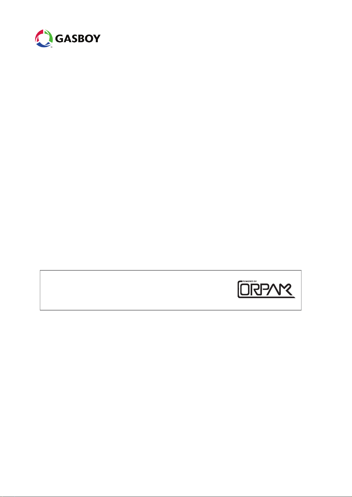
Figure 1-1 shows a basic diagram of Gasboy's Fuel Point PLUS architecture.
Fuel Point PLUS Station Equipment Manual 17
Page 18
Figure 1-1 - Fuel Point PLUS System Architecture
1.3. System Components
Fuel Point PLUS solution consists of theSo following components:
1.3.1. Station Equipment
Wireless Gateway
µWNR
1.3.2. Vehicle Units
Fuel Ring
DataPass
1.3.3. Tools
Wireless Vehicle Programmer
Wireless Nozzle Reader Programmer
18 Fuel Point PLUS Station Equipment Manual
Page 19

1.4. Manual Structure
This manual comprises the following chapters:
Chapter 1: Introduction
This chapter provides a general description of Fuel Point PLUS wireless vehicle identification system.
Chapter 2: Wireless Gateway Description
This chapter provides a description of Wireless Gateway units.
Chapter 3: µWNR Description
This chapter provides a description of µWNR units.
Chapter 4: Designing the Network Layout
This chapter provides network design guidelines.
Chapter 5: Installing the Wireless Gateway
This chapter provides instructions for installing the Wireless Gateway outdoor units.
Chapter 6: Setting the Network
This chapter describes the setup of the Wireless Network.
Chapter 7: Programming WNR units
This chapter provides instructions for programming µWNR units.
Chapter 8: Setting the Station Controller
This chapter describes the settings required to configure the communication interface between the
Controller and the Master Wireless Gateway, when using Fuel Point PLUS system with Gasboy's
SiteOmat Station Controller.
Chapter 9: Maintenance
This chapter provides general maintenance guidelines for Wireless Gateway and µWNR units.
Chapter 10: Glossary
This chapter provides a glossary of abbreviations used in this manual.
Fuel Point PLUS Station Equipment Manual 19
Page 20
Appendix A: Site Survey
This appendix provides a site survey form.
Appendix B: µWNR-F Installation Instructions
This appendix provides instructions for installing µWNR-F units.
Appendix C: µWNR-B & µWNR-T Installation Instructions
This appendix provides instructions for installing µWNR-B and µWNR-T units.
1.5. Documentation Conventions
This manual uses the following conventions:
Warning: Warning notes contain information that, unless strictly observed, could result in
injury or loss of life.
Caution: Caution notes contain information that, unless strictly observed, could result in
damage or destruction of the equipment or long-term health hazards to personnel.
Note: Notes contain helpful comments or references to material not covered in the
manual.
Best Practice: Best practice notes contain helpful suggestions.
Example: Example notes contain additional information to illustrate a concept/procedure.
20 Fuel Point PLUS Station Equipment Manual
Page 21

1.6. References
For additional and complementary information regarding Fuel Point PLUS, please refer to the following
manuals:
Fuel Point PLUS Vehicle Units Installation and Programming Manual P/N MDE-4868
Fuel Point PLUS Station Equipment Manual 21
Page 22

Page 23

CHAPTER 2 WIRELESS GATEWAY
DESCRIPTION
2.1. General
This chapter provides a description of Wireless Gateway units.
The Wireless Gateway Terminal (Wireless Gateway) units form the Wireless Network that
covers the forecourt
The units communicate through low power short range RF in the ISM 2.4 GHz band
Connected in a mesh topology, each unit captures data, but also serves as a relay for other
units, constituting a robust and reliable network, where all messages reaches their destination
bypassing any possible interferences
The Wireless Gateway receives both the and data, decrypts the information and forwards it to
the Station Controller in a secure manner
During refueling, the continues monitoring the signal to detect any attempt to remove the
nozzle and refuel other vehicle on the same account
2.2. Types of Wireless Gateway
There are two types of Wireless Gateway units:
Master Wireless Gateway: the unit connected to the Station Controller via LAN and master of
the Wireless Network
Wireless Gateway : units that function as a router in the Fuel Point PLUS station. No LAN
connection required
Figure 2-1 shows a simplified network diagram to stress the difference between the units.
Fuel Point PLUS Station Equipment Manual 23
Page 24
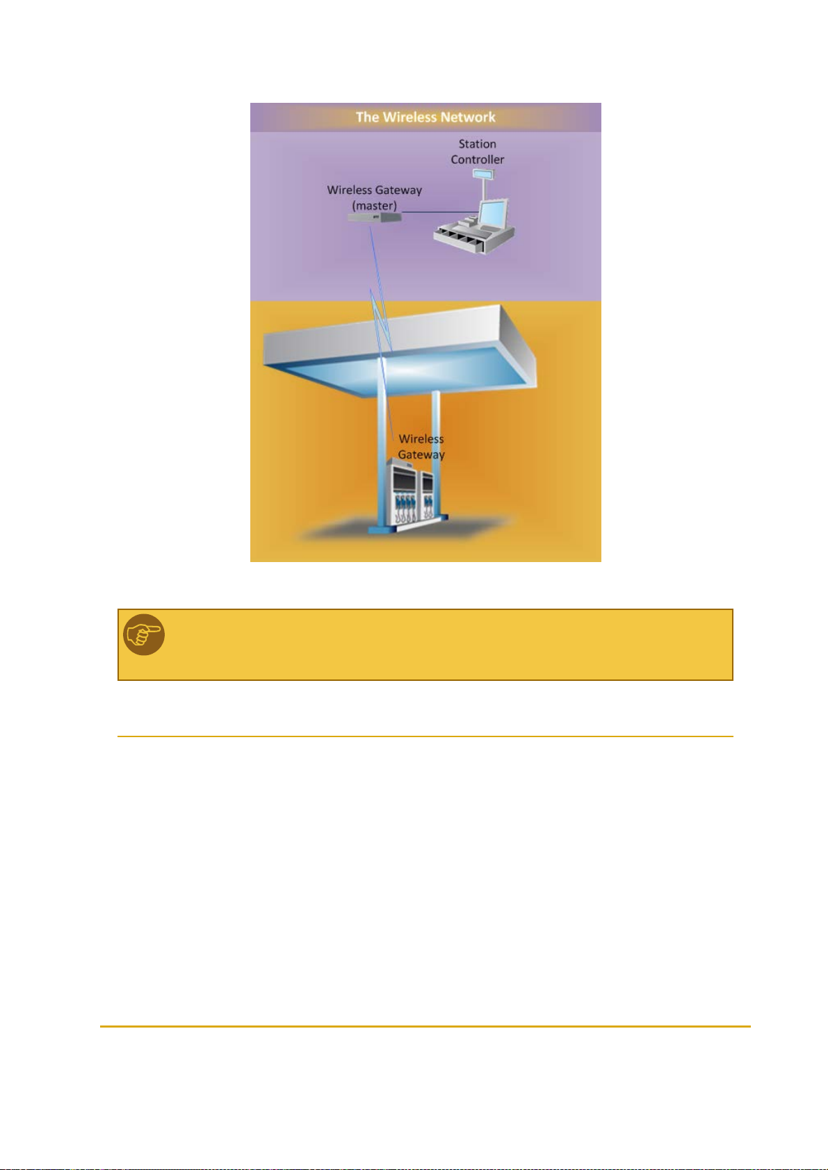
Figure 2-1 - Wireless Gateway Types
Note: A station must include one Master Wireless Gateway. This unit also functions as
Administrator.
2.3. Housing Options
The Master Wireless Gateway/Wireless Gateway units are available in the following housing options:
2.3.1. Wireless Gateway Outdoor Compact Box
Compact outdoor box (see Figure 2-2) specially designed for:
24 Fuel Point PLUS Station Equipment Manual
Page 25
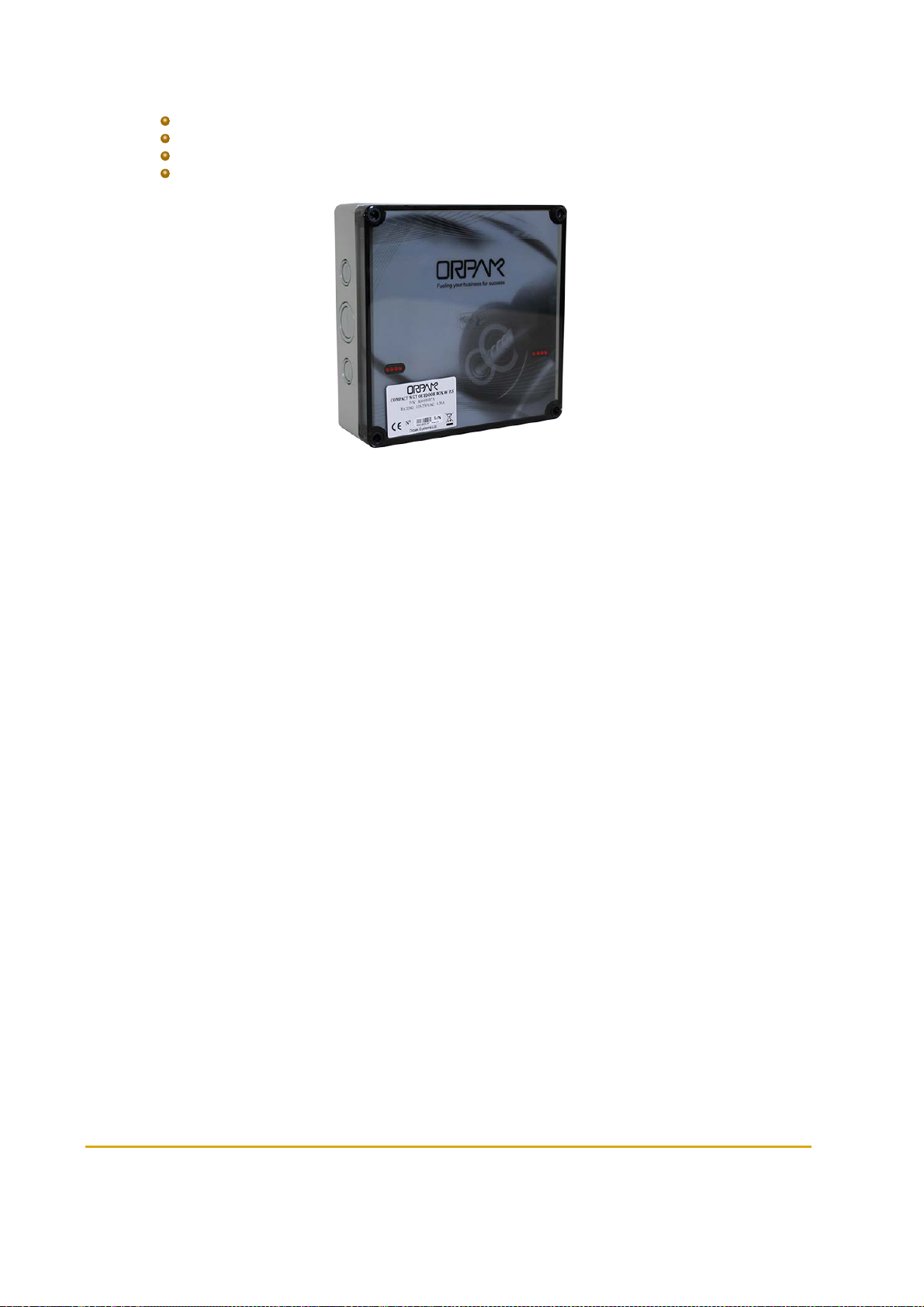
Installation on top of the pumps/dispensers
Installation in the station's office, C-Store
Prepared for wall-mounting
Includes optional integrated power supply
Figure 2-2 - Wireless Gateway Outdoor Compact Box
2.3.1.1. Wireless Gateway Outdoor Compact Box - Integrated P/S Specifications
(See Table 2-1)
Fuel Point PLUS Station Equipment Manual 25
Page 26

Table 2-1 - Wireless Gateway Outdoor Compact Box - Integrated P/S
Specifications
Parameter Value
PHYSICAL
Height 180 mm (7.087")
Width 182 mm (7.165")
Dept h 62.5 mm (2.461")
Weight 0.86 Kg
ELECTRICAL
Operating voltage 12 - 28 VDC
Operating current 0.5 A
ENVIRONMENTAL
Operating temperature -40°C to +55°C (-40°F to +131°F)
Humidit y 95% RH
COMMUNICATION
TCP/IP o ver Ethernet
EIA 802.15.4
2.405- 2.480 GHz ISM band RF Network Communication with AES128 encryption
POWERSUPPLY
DC o utput voltage 12 - 28 VDC
Rated current 0.35 A
Current range 0~0.625 A
Rated po wer 15 W
Voltage tolerance 1.0%
Line regulation 0.5%
Load regulatio n 0.5%
Input voltage range 85~264 VAC
Frequency range 47~63 Hz
AC cu rrent (typ ical) 0.35 A/115 VAC 0.25 A/230 VAC
26 Fuel Point PLUS Station Equipment Manual
Page 27

2.3.1.2. Wireless Gateway Outdoor Compact Box Specifications
(See Table 2-2)
Table 2-2 - Wireless Gateway Outdoor Compact Box Specifications
Parameter Value
PHYSICAL
Height 180 mm (7.087")
Width 182 mm (7.165")
Dept h 62.5 mm (2.461")
Weight 0.73 Kg
ELECTRICAL
Operating voltage 12 - 28 VDC
Operating current 0.5 A
ENVIRONMENTAL
Operating temperature -40°C to +55°C (-40°F to +131°F)
Humidit y 95% RH
COMMUNICATION
TCP/IP o ver Ethernet
EIA 802.15.4
2.405- 2.480 GHz ISM band RF Network Communication with AES128 encryption
2.3.2. Wireless Gateway Outdoor
Outdoor box (see Figure 2-3) specially designed for:
Installation on top of the pumps/dispensers
Installation in the station's office, C-Store
Prepared for wall-mounting
Includes optional integrated power supply
Fuel Point PLUS Station Equipment Manual 27
Page 28
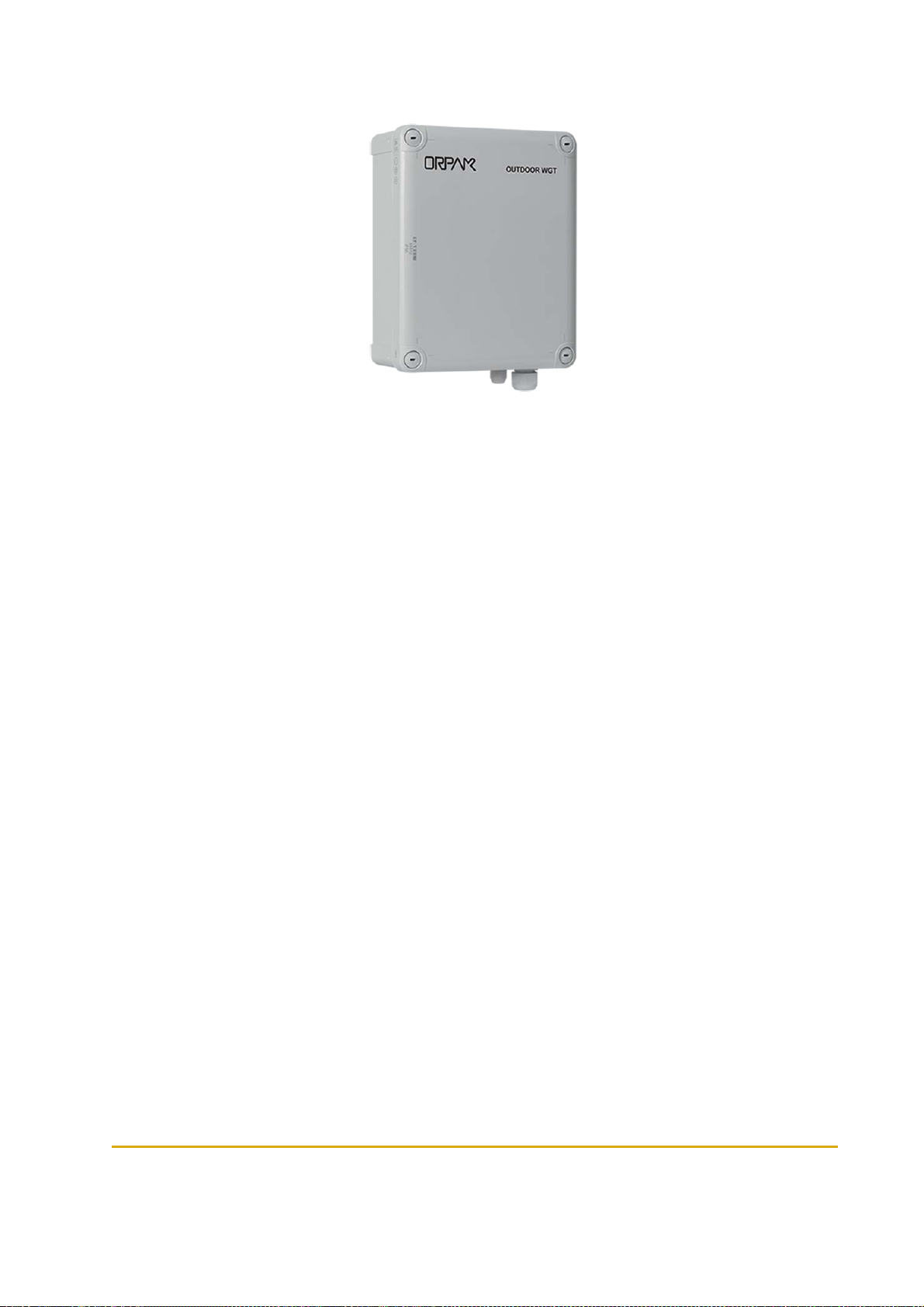
Figure 2-3 - Wireless Gateway Outdoor
2.3.2.1. Wireless Gateway Outdoor - Integrated P/S Specifications
(See Table 2-3)
28 Fuel Point PLUS Station Equipment Manual
Page 29

Table 2-3 - Wireless Gateway Outdoor Integrated P/S Specifications
Parameter Value
PHYSICAL
Height 280 mm (11.024")
Width 190 mm (7.485")
Dept h 130 mm (5.1118")
Weight 1.6 Kg
ELECTRICAL
Operating voltage 12 - 28 VDC
Operating current 0.5 A
ENVIRONMENTAL
Operating temperature -40°C to +55°C (-40°F to +131°F)
Humidit y 95% RH
COMMUNICATION
TCP/IP o ver Ethernet
EIA 802.15.4
2.405- 2.480 GHz ISM band RF Network Communication with AES128 encryption
POWERSUPPLY
DC o utput voltage 12 - 28 VDC
Rated current 0.35 A
Current range 0~0.625 A
Rated po wer 15 W
Voltage tolerance 1.0%
Line regulation 0.5%
Load regulatio n 0.5%
Input voltage range 85~264 VAC
Frequency range 47~63 Hz
AC cu rrent (typ ical) 0.35 A/115 VAC 0.25 A/230 VAC
Fuel Point PLUS Station Equipment Manual 29
Page 30
2.3.2.2. Wireless Gateway Outdoor Specifications
(See Table 2-4)
Table 2-4 - WGT Outdoor Specifications
Parameter Value
PHYSICAL
Height 280 mm (11.024")
Width 190 mm (7.485")
Dept h 130 mm (5.1118")
Weight 0.8 Kg
ELECTRICAL
Operating voltage 12 - 28 VDC
Operating current 0.5 A
ENVIRONMENTAL
Operating temperature -40°C to +55°C (-40°F to +131°F)
Humidit y 95% RH
COMMUNICATION
TCP/IP o ver Ethernet
EIA 802.15.4
2.405- 2.480 GHz ISM band RF Network Communication with AES128 encryption
2.3.3. Wireless Gateway In-Pump
The box (see Figure 2-4) is specially designed for:
Integration into pumps/dispensers
Installation in IslanderPLUS/ICR PLUS Station Controller pedestals
Figure 2-4 - Wireless Gateway In-Pump
30 Fuel Point PLUS Station Equipment Manual
Page 31

2.3.3.1. Wireless Gateway In-Pump Specifications
(See Table 2-5)
Table 2-5 - Wireless Gateway In-Pump Specifications
Parameter Value
PHYSICAL
Height 41 mm ( 1.6")
Width 201 mm (7.9")
Dept h 120 mm (4.7")
Weight 0.36 Kg
ELECTRICAL
Operating voltage 12 - 28 V DC
Operating current 0.5 A
ENVIRONMENTAL
Operating temperature -40°C to +55°C (-40°F to +131°F)
Humidit y 95% RH
COMMUNICATION
TCP/IP o ver Ethernet
EIA 802.15.4
2.405- 2.480 GHz ISM band RF Network Communication with AES128 encryption
Fuel Point PLUS Station Equipment Manual 31
Page 32

Page 33

CHAPTER 3 WNR DESCRIPTION
3.1. General
This chapter provides a description of µWNR units.
3.2. Types of µWNR
There are three types of µWNR units:
µWNR-F: For front installation on the base of the spout. Both the electronic components and
the antenna reside in the same housing
µWNR-B: For back installation on the rear of the nozzle, ideal for large and vapor recovery
nozzles. Only the antenna is installed on the base of the spout, while the µWNR back housing
is mounted on a provided adaptor between the nozzle and the hose
µWNR-T: For cistern trucks. Similar to µWNR-Bwith addition of an activation switch to prevent
unnecessary activations of the unit caused by the fueling truck's motion
3.3. Using the µWNR
Once the it has been installed and programmed, the unit becomes automatically activated
when it is tilted (i.e. when removed from the cradle). At this stage the LED indicator blinks
once, meaning that the unit is ON and searching for Fuel Ring devices
When a fueling nozzle is inserted into the vehicle's fuel inlet and the µWNR detects the Fuel
Ring the LED indicator will blink twice. The µWNR send encrypted RFID data to the Wireless
Gateway
The µWNR will be kept activated and monitored during the course of the transaction to ensure
that the nozzle is not removed while the pump is dispensing, preventing fraud and misuse
3.4. µWNR Specifications
(See Table 3-1)
Fuel Point PLUS Station Equipment Manual 33
Page 34

Table 3-1 - µWNR Specifications
Parameter Value
PHYSICAL
µWNR-F Housing Dimensions (HxWxD) 106.1x56.9x72.2mm (4.173x2.24x1.74")
µWNR-B Back Clamp Dimensio ns ( HxWxD) 76.8x68x48.7mm (3.024x2.677x1.917")
ELECTRICAL
Batt eries P/N 812539200 ( x2)
Power Consumpt ion
ENVIRONMENTAL
Operating temperature -40°C to +60°C (-40°F to +140°F)
Storage temperature -40°C to +60°C (-40°F to +140°F)
COMMUNICATION
RF communication to Wireless Gateway
RFID communication method with Fuel Rin g Frequency: 119-135 kHz
Active mode: 25mA typical.
Standby mode: 20µA
Frequency: 2.405-2.480 GHz. Typical transmission power: 3dbm (2mW)
34 Fuel Point PLUS Station Equipment Manual
Page 35

CHAPTER 4 DESIGNING THE NETWORK
LAYOUT
4.1. General
The following provides network design guidelines and recommendations to help in determining which
equipment should be installed and at which location, so maximum coverage of the forecourt is achieved
without obstacles and interferences.
4.2. Site Survey
To ensure maximum network coverage a site survey should be carried out prior to installing station
equipment. The following data should be gathered:
Number of dispensers equipped with Fuel Point PLUS
Interface to Station Controller (LAN line)
Distance between the islands and the dispensers within each island (station topology)
Possible sources of interference (trucks and other large metal objects)
Wireless Gateway outdoor optimal location from an aesthetic point of view
Non-standard length hoses (used when vehicle's fuel filler is not siding the pump)
Once mapping is done, you'd need to define how to build the Wireless Gateway network, considering:
Number of Wireless Gateway units (including the Master Wireless Gateway) are needed
Types of Wireless Gateway to be used: In-Pump (in the pump, or inside Home-Base
pedestals) or Outdoor
Master Wireless Gateway and Wireless Gateway units location
4.3. Wireless Gateway Positioning
Figure 4-1 shows the Wireless Gateway RF lobe in approximation.
Most of the RF signal is spread upwards and to the sides
In Outdoor units the signal is the strongest in the direction of the front cover
In indoor units, the signal spreads mostly up, but since the signal is reflected inside the
dispenser, it has less significance
Fuel Point PLUS Station Equipment Manual 35
Page 36

Figure 4-1 - Wireless Gateway RF Lobe (Approx. for Illustration Purposes Only)
Outdoor units should be installed so the RF lobe is directed to the area to be covered:
If installed on a wall, the front panel should face the covered area and the other
Wireless Gateway units
If installed on the canopy, the front panel should be facing down
If installed on top of the dispenser or on other horizontal surface, the front panel
should be facing up, as long as the Wireless Gateway is not installed higher than
1.5-2m/5-6ft
In-Pump units should be placed in the dispenser head, in the center or behind the display
Note: Some dispenser heads may substantially block the RF signal. In this cases, use an
Outdoor unit instead.
4.4. Location Recommendations
Take into account the following recommendations:
Maintain a clear line of sight between the Wireless Gateway units as much as possible
If an Outdoor unit is used, install it as high as possible
Install an Outdoor unit on the canopy if possible from maintenance and
infrastructure point of view
If there is LAN connection in the forecourt, place the Master Wireless Gateway on the island
and not on the station office/store wall
Best Practice: Use Outdoor units whenever possible to prevent signal from being blocked
by the metal housing of the dispenser head.
36 Fuel Point PLUS Station Equipment Manual
Page 37

4.5. Maximum Distance
Maximum distance between Wireless Gateway units should not exceed the following values (see Table 4-
1).
Table 4-1 - Maximum Recommended Distance between
Wireless Gateway Units
Wireless Gateway#1 Wireless Gateway#2 Distance
In-Pump In-Pump 10m/32ft
Outdoor In-Pump 15m/50ft
Outdoor Outdoor 20m/65ft
Outdoor >3m/10ft height Outdoor >3m/10ft height 30m/100ft
Note: Values apply to clear LOS without obstacles.
Maximum distance between µWNR and the closest Wireless Gateway unit should not exceed the
following values (see Table 4-2).
Table 4-2 - Maximum Recommended Distance between
Wireless Gateway and µWNR
Wireless Gateway Type Distance
Notes:
In-Pump 10m/32ft
Outdoor 20m/65ft
Outdoor >3m/10ft height 30m/100ft
Values apply to clear LOS without obstacles
The fueling vehicle can be an obstacle when the fuel filler is not siding the pump.
In this case, inlet is on the far side of the vehicle (not next to the dispenser). In
such case, do one of the following:
Use an Outdoor unit installed at a higher height
Install an additional unit at the far side (i.e. the next island)
Fuel Point PLUS Station Equipment Manual 37
Page 38

4.6. Network Design Scenarios
The Wireless Network can include a different number of Wireless Gateway units, depending on the
station size and the area to be covered.
Multiple units ensure full coverage of the entire forecourt all the time and allow optional paths for the
signal to prevent network interferences from trucks and other large metal objects.
Following are different design scenarios. Please note that there is not one way to locate the units, it is
strongly dependent upon station topology and the level of coverage needed.
4.6.1. Scenario #1 - 1 Master Wireless Gateway Outdoor
(See Figure 4-2)
Coverage: 1 island
Conditions: LAN line to the island (for communication to Station Controller)
Figure 4-2 - Scenario No.1
4.6.2. Scenario #2 - 1 Master Wireless Gateway Outdoor + 1 Wireless Gateway Outdoor
(See Figure 4-3)
Coverage: 1 island
Conditions: Maximum distance between units: 20m/65ft
38 Fuel Point PLUS Station Equipment Manual
Page 39

Figure 4-3 - Scenario No. 2
4.6.3. Scenario #3 - 1 Master Wireless Gateway Outdoor + 1 Wireless Gateway Outdoor Per Island
(See Figure 4-4)
Coverage: All islands
Conditions: Maximum distance between units: 20m/65ft
Figure 4-4 - Scenario No. 3
4.6.4. Scenario #4 - 1 Master Wireless Gateway Outdoor + 2 Wireless Gateway In-Pump Per Island
(See Figure 4-5)
Fuel Point PLUS Station Equipment Manual 39
Page 40

Coverage: All islands
Conditions:
Maximum distance between units: 10m/32ft.
Maximum distance between Master Wireless Gateway and closest Wireless
Gateway unit: 15m/50ft
Figure 4-5 - Scenario No. 4
40 Fuel Point PLUS Station Equipment Manual
Page 41

CHAPTER 5 INSTALLING THE WIRELESS
GATEWAY
5.1. General
The following provides instructions for installing the Wireless Gateway outdoor units.
Note: Wireless Gateway In-Pump units are installed in Station Controller
pedestals/cabinets and in pump-heads. Since guidelines vary according to dispenser
model, please contact us for more information.
5.2. Installation Options
The following installation options are available:
Mounting on a wall or a on an existing pole
Installing on the canopy
Mounting on a dedicated pole or pedestal
Note: The method to be used depends on station layout and configuration, installation
should comply with UL an UE requirements.
Note: If mounted on a dedicated pole, installation of the pole in the Island must comply
with the UL/EU or any local regulations requirements while securing the pole to the
concrete floor, laying cables and placing the Wireless Gateway outside the hazardous
location.
Fuel Point PLUS Station Equipment Manual 41
Page 42
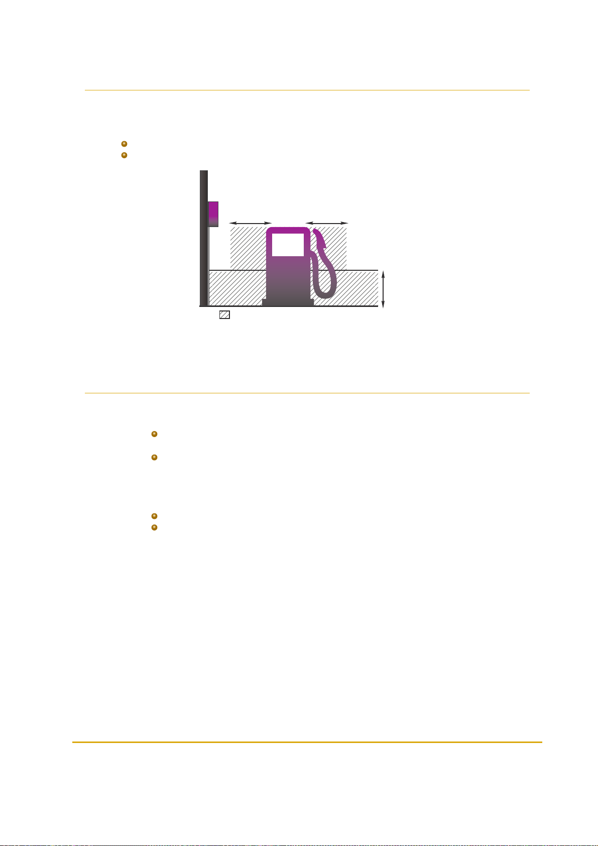
5.3. Approved Location
18"/0.45m
18"/0.45m
18"/0.45m
Wireless
Gateway
Outdoor
Class I Div 2 Safety Area
Due to safety requirements, the Wireless Gateway outdoor must be installed at non-hazardous area/nonclassified area (see Figure 5-1):
Above 18” (0.5 meter) from the Isle floor
At least 18” (0.5 meter) away from the dispenser
Figure 5-1 - Approved Location
5.4. Installation Instructions
1.
Remove the Wireless Gateway front panel
2.
Remove the cable entry knockout plates on the bottom panel:
For Master Wireless Gateway remove two panels (one for LAN and one for Power
cables)
For Wireless Gateway remove one panel for the Power cable
3.
Place the unit vertically with cable entry openings facing down
4.
Secure the unit to a flat surface, inserting four screws in the mounting openings located at the four
corners of the unit (see Figure 5-2, Figure 5-3
5.
Connect power supply:
For units equipped with integrated P/S: Connect AC P/S to the AC terminal
For units without integrated P/S: connect a 12-28 VDC (stabilized),0.5A power supply
to the Power Connector
Use an external AC to DC or DC to DC switching power supply transformer approved
according to the local regulations. In North America use a AC to DC NEC Class 2 power
supply, low voltage and low current maximum 100 VA even under fault conditions. The
power supply can be installed in the office, in the pedestal, in the tanker truck cabin (DC
to DC power supply) or in a separate box
42 Fuel Point PLUS Station Equipment Manual
Page 43

6. Master Wireless Gateway only: Connect a shielded S-CAT5E cable to the RJ45 Ethernet
connector
7.
Replace the front panel and secure it using the four coarse thread plastic screws
Figure 5-2 - Outdoor Box Dimensions
Fuel Point PLUS Station Equipment Manual 43
Page 44

Figure 5-3 - Outdoor Compact Box Dimensions
Note: If power supply is installed far from the Wireless Gatewayunit, verify that there is no
power line leakage and that the unit receives correct voltage.
Note:
Thread the cables through UL listed glands or appropriate metal tubing.
The large opening can host a gland for cables of a diameter between
5.8mm/0.230” to 13.9 mm/0.530”, while the small openings are suitable for a
diameter between 2.9mm/0.114” to 6.4mm/0.250”. Tighten the glands in order to
prevent the intrusion of water or gases through conduits, cables and conductors
Do not damage unit sealing (IP66 protection)
44 Fuel Point PLUS Station Equipment Manual
Page 45
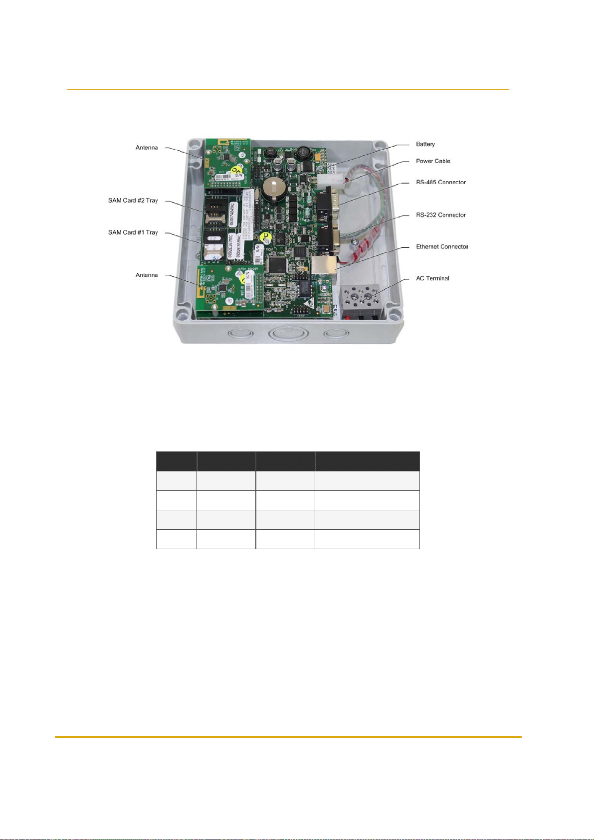
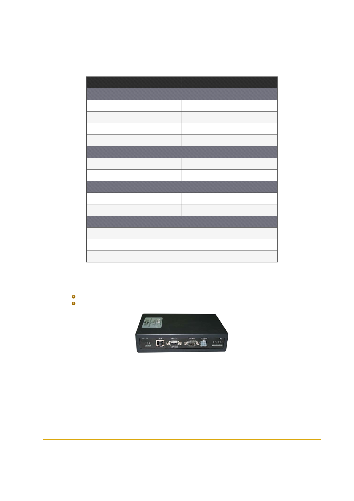
5.5. Connectors & Indicators
Figure 5-4 shows the Wireless Gateway main components.
Figure 5-4 - Wireless Gateway Components
5.5.1. DC Power Input CN8 Molex Connector
(See Table 5-1)
Table 5-1 - DC Power Input Connector Pinout
Pin. # Description Wire Color Notes
4 DC INPUT +V Red
2 DC INPUT -V Black
1 GND Yellow/Green Connect to nearest ground
3 PF Not in use
5.5.2. RS-485 Communication CN12 D9P Connector
(See Table 5-2)
Fuel Point PLUS Station Equipment Manual 45
Page 46

Table 5-2 - RS-485 Communication Connector Pinout
Pin. # Descript ion
Chan nel 1
1 +485
2 -485
6 G485
Chan nel
3 +485
4 -485
8 G485
7,9, case GND
5 N.C.
5.5.3. RS-232 Communication CN11 D9S Connector
(See Table 5-3)
Table 5-3 - RS-232 Communication Connector Pinout
Pin. # Description Notes
2 TXD_232
3 RXD_232
5 Ground_232
8 MONITOR Refer to monitor jumpers (Rev C only)
4 MONITOR Refer to monitor jumpers (Rev D only)
7 CAN_H (Rev D only)
8 CAN_L (Rev D only)
9 CAN_Ground (Rev D only)
4,6,9 N.C. (Rev C only)
1 N.C.
5.5.4. Factory Default Jumper Settings
(See Table 5-4)
46 Fuel Point PLUS Station Equipment Manual
Page 47

Caution: Only authorized technicians are allowed to modify jumper default settings.
Jumper # Name Description
J2 Watch Dog
J3 Reset
J4 (Pins 1-2) 3.3.V SAM power 3.3V
J4 (Pins 2-3) 5V SAM power 5V
5.5.5. LED Indicators
(See Table 5-5 and Table 5-6)
LED # Name Descript ion
DL2 100
DL3 ACT Blinksduring active communication
Table 5-4 - Jumper Settings
Table 5-5 - LEDs - PCB left side
Indicates communication rate:
Lit: 100 BPS
Off: 10 BPS
DL4 LNK Constantly lit when Ethernet is connected
Table 5-6 - LEDs - PCB Right Side
LED # Name Description
Constantly lit
DL9 GP
TAG Not used
RST Lights during reset
5V Indicates that +5V is active
DL7 3V Indicatesthat +3.3V isactive
DL8 1V8 Indicates that +1.8V is active
Blinks during data transfer over external
communication (Ethernet, RS-232, RS-485)
Fuel Point PLUS Station Equipment Manual 47
Page 48

Page 49

CHAPTER 6 SETTING THE NETWORK
6.1. General
The following describes the setup of the Wireless Network.
You can easily set-up the Wireless Network using the Setup Site.This site also gives you full access to
all Fuel Point PLUS components in the forecourt: Wireless Gateway, µWNR and DataPass for setup,
remote software updates and remote maintenance tasks.
6.2. Basic Steps for Setting the Wireless Network
1. Install the Wireless Gateway units. See Installing the Wireless Gateway
2.
Install the µWNR units. See Online Help
3. Set the Master Wireless Gateway. See Setting the Master Wireless Gateway
4. Set the Wireless Gateway units. See Setting the Wireless Gateway Units
5. Set the µWNR units. See Programming WNR Units
6. Verify that all network components are communicating properly. See Monitoring Station
Equipment
6.3. Connecting the PC to the Unit
After the Master Wireless Gateway and Wireless Gateway units have been connected, proceed to
connect your PC :
1. Connect your PC to the unit's RJ-45 connector using a LAN cable (see Figure 6-1)
Figure 6-1 - Wireless Gateway LAN Connectors
Fuel Point PLUS Station Equipment Manual 49
Page 50

2. Set your PC's IP to 192.168.1.XXX
3. Then, type this IP address in the browser's address box: http://192.168.1.170. The Home Page is
displayed.
6.4. Setup Site Home Page
This is the Home Page for a Master Wireless Gateway unit (see Figure 6-2)
Figure 6-2 - Master Wireless Gateway Home Page
This is the Home Page for a Wireless Gateway unit (see Figure 6-3)
Figure 6-3 - Wireless Gateway Home Page
50 Fuel Point PLUS Station Equipment Manual
Page 51

The Home Page includes navigation buttons (see Table 6-1) and the unit details (see Table 6-2):
Table 6-1 - Home Page - Navigation Buttons
Button Description
Returns to the Home Page
See Set ting the Mast er Wireless Gateway for a Master WirelessGateway, or
Setting t he Wireless Gateway Units for Wireless Gateway units
See Viewing Network Status
See Performing Administrator Tasks
See Updating Software Lo cally
Curr ently N/A
Table 6-2 - Home Page - Wireless Gateway Details
Item Description
Ethernet IP Unit'sIP address. Default: 192.168.170
Ethernet MAC Media AccessControl address
Version Application version
AVR1 Version AVR1 transmitting antenna version
AVR2 Version AVR2 transmitting antenna version
Boo tLoader Version Curr ent boot loader version
Station ID
Logical Address
Location Descriptive free text to easily identify the unit
ID number of the station. Must be identicalfor Master Wireless Gateway and all WirelessGateway units
Unique logicaladdress that identifies the unit within the networ k. Master Wireless
Gateway default is 1 and cannot be changed. Wireless Gateway can be setto any
number between 3 and 254
Click Setup. A login dialog appears (see Figure 6-4). Enter your user credentials. Default username is
advanced
Fuel Point PLUS Station Equipment Manual 51
Page 52

Figure 6-4 - Wireless Gateway Setup Site Login Dialog Box
Best Practice: Since most Wireless Network settings are done via Master Wireless
Gateway, it's highly recommended to set the Master Wireless Gateway and then proceed
to set a few parameters in each WGT unit.
6.5. Setting the Master Wireless Gateway
After logging into the Master Wireless Gateway and clicking Setup, the Wireless Gateway Map screen
appears. (see Figure 6-5)
Figure 6-5 - Wireless Gateway Map Screen
This screen displays a button for each unit in the network. At this stage, only the Master Wireless
Gateway is shown, since Wireless Gateway units haven't been defined yet.
52 Fuel Point PLUS Station Equipment Manual
Page 53

Click on Master Wireless Gateway button.
The Setup screen appears. (see Figure 6-6)
Figure 6-6 - Setup Screen
Master Wireless Gateway setup is performed by simply going through the following tabs:
6.5.1. Setting Minimal Setup
6.5.2. General Setup
6.5.3. WNR Configuration List
6.5.4. Setting Group Communication
6.5.5. WNR Setup
6.5.6. Security & DP SW
6.5.7. Log Level
6.5.8. Saving Setup
6.5.1. Setting Minimal Setup
This tab enables you to set the necessary parameters for establishing the Wireless Network. (See Figure
6-7, Table 6-3).
Fuel Point PLUS Station Equipment Manual 53
Page 54

Figure 6-7 - Minimal Setup
1. In the Station ID field, enter the ID number of the station. This code must be identical for all the
Wireless Gateway units in the station
2. (Optional) In the Location field, enter a descriptive free-text to easily identify the unit
3. In the Wireless Active Channels section, select two nonconsecutive channels
4. Click Submit
Notes:
Select the same channels for each Wireless Gateway unit in the station
If there is another station with Wireless Network in the proximity, make sure to
select different channels
Also verify that these frequencies do not cause interference to other equipment
in the station
Note: When setting up a unit for the first time, you must always click Submit before
continuing to the next tab. If not, the following message appears (see Figure 6-8):
54 Fuel Point PLUS Station Equipment Manual
Page 55

Figure 6-8 - Submit Button Warning
Table 6-3 - Minimal Setup Parameters
Parameter
Station ID ID number of the station. Must be identical for Master Wireless Gateway and all Wireless Gateway units
Descript ion
Logical Address
Location Descriptivefree text to easily identify the unit
Wireless Gateway Type
Wireless Active
Chan nels
Setup Sou rce
Submit Saves the settingsof the curr ent tab. To applythe changes, see Saving Setup
Resto re Factory
Setup
Unique logicaladdress that identifies the unit within the networ k. Master Wireless Gateway default is 1
and cannot be changed, and so thisfield is disabled
Select Default for Master Wireless Gateway
Select Manu ally for a Wireless Gateway unit
Wirelesschannels for network communication between the units. Select two nonconsecutive channels
Enables importing a setup file
Select From Setup File to import an .XML file (see below)
Select Manu ally to manually set the network
Restores factory default settings by selecting the default version fr om the drop-down list ( WW, unless
otherwisespecified by ProfessionalServices) and then clicking on the Restore Factory Setup button
6.5.1.1. Importing Setup
Once you have setup a network, you can save the .XML setup file instead of manually setting up the
Wireless Network. See Exporting Setup.
Then you may import those settings and override the parameters as needed (i.e. Wireless Channels ,
µWNR settings, etc.) to match the configuration of the station.
1. Select the From Setup File radio button
2. Click Browse. A file selection dialog appears
3. Select the .XML file and click Open
4. Click Upload
5. Click Submit
6.
Override the network settings as needed
7. Apply the changes. See Saving Setup
Fuel Point PLUS Station Equipment Manual 55
Page 56

6.5.2. General Setup
This tab enables you to set the general Wireless Network parameters. (see Figure 6-9, Table 6-4).
Set the parameters as needed and then click Submit.
Figure 6-9 - General Setup
Table 6-4 - General Setup Parameters
Parameter Descript ion
Ethernet Conf iguration
IP Address Master WirelessGateway IP address
Subn et Mask IP network mask
Defau lt Gateway Router IP (in cases where a router isconnected to the network)
DHCP Curr ently not in use
FCC Con figuration
NoData Timeout Maximum waiting time for connection to the Controller, before the Master WirelessGateway resets
RTC
Date Real time clock- date
Time Real time clock- time
General
Station Type Selectthe relevant type from the drop-down list: Ret ail or In -House
56 Fuel Point PLUS Station Equipment Manual
Page 57
Parameter Descript ion
SAM Cards Select according to the number of SAMcards installed in the unit
OrData
Select Yes if the station is equipped with and OrData system
Port
Station Tag Numbers
Add Tag ClickAdd Tag to enter the string of the tag to be used in the station
Remove Tag Click Remove Tag to delete an already defined tag
Submit Saves the settings of the current tab. To applythe changes, see Saving Setup
When OrData is enabled, thisfieldis displayed.Enter the number of the port for communication
between Master Wireless Gateway and OrData. Default: 7000
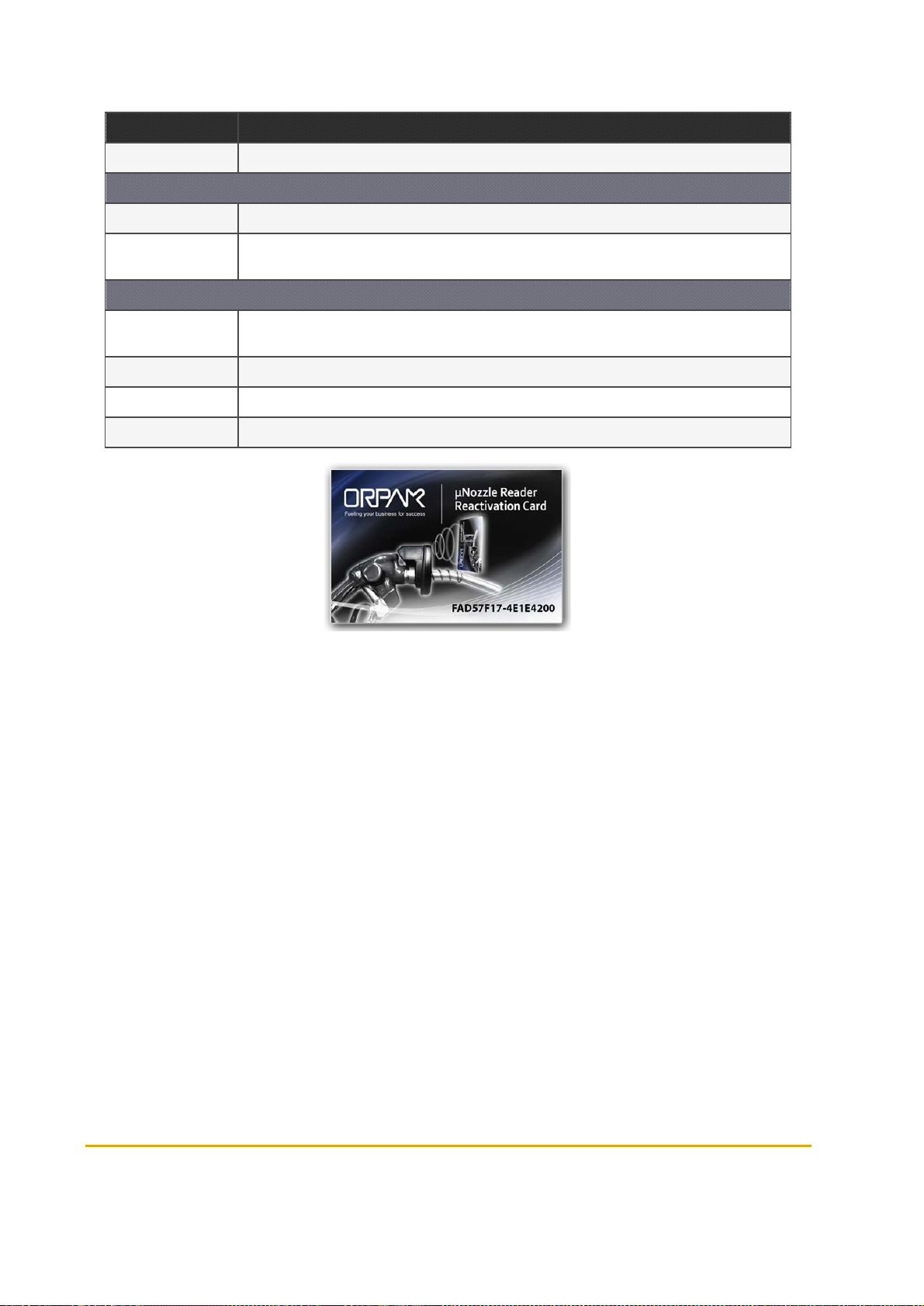
The Station Manager tag (see Figure 6-10) isused for reactivating deactivated µWNR units.Up to 5
Station Manager Tags can be defined.
Figure 6-10 - Station Manager Card
6.5.3. WNR Configuration List
This tab enables you to associate the µWNR with the Wireless Gateway unit (Master Wireless Gateway
or Wireless Gateway). (see Figure 6-11, Table 6-5).
Fuel Point PLUS Station Equipment Manual 57
Page 58

Figure 6-11 - WNR Con List
1. In the Pump# field, enter the number of the pump to which the µWNR is associated
2. In the Nozzle# field, Enter the number of the nozzle on which the µWNR is installed
3. Select the WNRExist? checkbox
4. In the Wireless Gateway Address field, enter the logical address of the Wireless Gateway to
which the µWNR is routed
5.
Repeat Steps 1-4 for each µWNR in the station
6. Click Submit
Note: Pump# and Nozzle# must mach the µWNR settings done while programming the
unit. See Programming WNR Units
Table 6-5 - WNR Con List Elements
Element Descript ion
Chan nel Logical channel for communication with the controller
Pump #
Nozzle #
NR Exist ? Specifies whether the nozzle is equipped with a WirelessNozzle Reader. Thischeckboxmust be selected
Number of the pump to which the Wireless Nozzle Reader isassociated. This number must match Wireless
Nozzle Reader settings
Number of the nozzle on which the WirelessNozzle Readeris installed. This number must match Wireless
Nozzle Reader settings
58 Fuel Point PLUS Station Equipment Manual
Page 59
Element Descript ion
Logicaladdress of the Wireless Gateway to which the Wireless Nozzle Reader isrouted
WGT
Add ress
Group
Setup
Source
Statu s Table
Submit Saves the settings of the curr ent tab. To applythe changes, see Saving Setup
Note: A Maste r Wireless Gateway/WGT unit can support up to 16 Wireless Nozzle Readers
As part of WirelessGateway-Station Controller protocol, Wireless Nozzle Readers are grouped into a
group of 16 units. Each unit is assigned a Channel number. If the station is equipped with more than 16 WirelessNozzle Readers, you may add groups as needed, byclicking Ad d Grou p. Up to 7 groups can be
defined ( 112 Wireless Nozzle Readers)
Enables importing a Wireless Nozzle Readers setup file :
Leave the default option selected - Manually to manuallyfill in the fields in this screen
Select From Setup File to import an .XML file
The Auto o ption is curren tly N/A
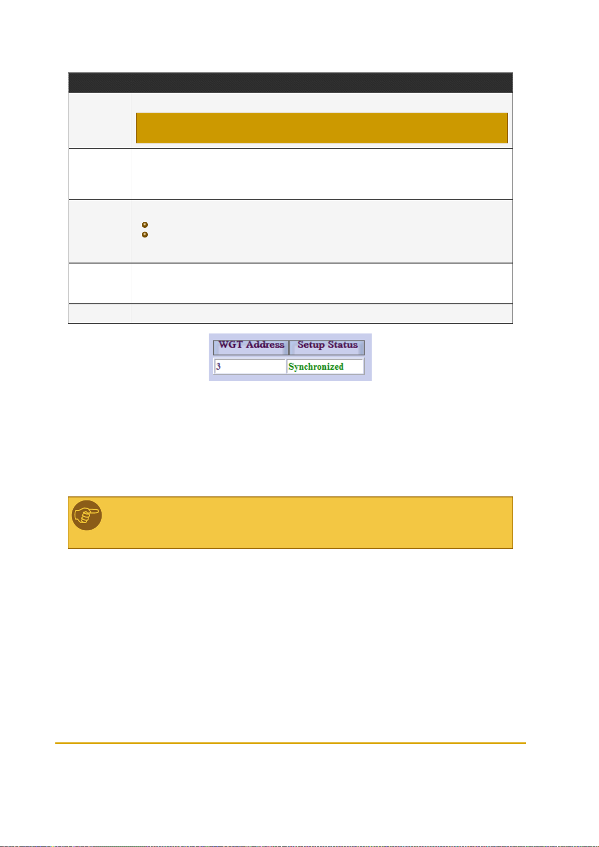
Once Master WirelessGateway and the Wireless Gateway unitshave been set-up, thistable (see Figure 6-
12) shows the status of the Wireless Gateways . Verify that the status of allthe unitsisSynchronized.
Nevertheless, at this point the table should be empty
Figure 6-12 - Status Table
6.5.4. Setting Group Communication
This tab enables you to set the communication channels between the groups of Wireless Nozzle Readers
set in the previous tab and the Station Controller. (See Figure 6-13, Table 6-6).
Note: These parameters must match the Station Controller. If you are using SiteOmat
Station Controller, see Setting the Station Controller.
Fuel Point PLUS Station Equipment Manual 59
Page 60

Figure 6-13 - Group Comm
1. In the FCC to Group section, in the Comm. Interface drop-down, select TCP/IP. Once this
option is selected the TCP/IP Port field is displayed
2. In the FCC to Group section, in the TCP/IP Port field enter the port number (between 3000 and
4000)
3. In the Group Communication section, in the Group Address field, enter the RS-485 address of
the group (between 31 and 39)
4. In the Group Communication section, in the Comm. Interface drop-down, select Wireless
5. Repeat Steps 1-4 for each Group defined while WNR Configuration List
6. Click Submit
Table 6-6 - Group Communication Fields
Field
FCC to Group
Communication interface between the Station Controller and the group. Usually, the Master Wireless Gateway is
Comm.
Interface
connected to the Station Controller via Ether net and therefore TCP/IP option should be selected
Note: Serial comm unication interfaces are a lso available for backwa rd compatibility to wired legacy syste ms.
Description
TCP/IP
Port
Group Communication
Port as defined in Station Controller (between 3000 and 4000)
60 Fuel Point PLUS Station Equipment Manual
Page 61

Field
Group
Add ress
Description
RS-485 address of the group (between 31 and 39). Despite the fact that Master Wireless Gateway is connected
to Station Controller via Ether net, thisparameter should be set since it ispart of Wireless Gateway-SC protocol
messages. If using SiteOmat, thisparameter should match the Hex Address field defined in VISSetup dialog.
See Set ting the Station Controller
Comm.
Interface
Submit Saves the settings of the current tab. To applythe changes, see Saving Setup
Communication interface between the Master Wireless Gateway and the other components in the group. Since
Master Wireless Gateway communicates to other WirelessGateway units and Wireless Nozzle Readers via a
wireless link, the Wireless option shouldbe selected
6.5.5. WNR Setup
This tab enables you to change advanced settings for the Wireless Nozzle Readers. (see Figure 6-14,
Table 6-7).
Set the parameters as needed and then click Submit.
Figure 6-14 - WNR Setup
Fuel Point PLUS Station Equipment Manual 61
Page 62

Table 6-7 - WNR Setup Elements
Parameter Descript ion
Vehicle Units
List
RSSI Nominal/Special
Levels
µWNR base
sample rate
Statu s Table
Submit Saves the settings of the current tab. To applythe changes, see Saving Setup
Sets which vehicle units should be read at the station.
Select All: selects all the units
Clear all: deselectsallthe units
Note: These fields are relevant for backward compat ibility to VIU 3/35/4/45 legacy vehicle units.
Sets the interval for sampling the Fuel Ring while refueling, to ensure that the nozzle is not removed
while the pump is dispensing. Default: 15 seconds
Once Master WirelessGateway and the Wireless Gateway unitshave been set-up, thistable (see Figure
6-15) shows the status of the WirelessGateways . Verifythat the status of all the unitsisSynchronized.
Nevertheless, at this point the table should be empty
Figure 6-15 - Status Table
6.5.6. Security & DP SW
The system enables you to remotely upgrade software versions of all wireless network components via
Master Wireless Gateway.
From this tab (see Figure 6-16, Table 6-8). you can define whether to upgrade DataPass in-vehicle unit
firmware with the latest version stored in Master Wireless Gateway, as soon as the vehicle arrives the
station. In addition, you may define various security settings
If your system is not equipped with DataPass units, or you'd like to leave these settings as is,
click Submit
Click on drop-down menu and select Yes to enable remote upgrade of DataPass units
62 Fuel Point PLUS Station Equipment Manual
Page 63
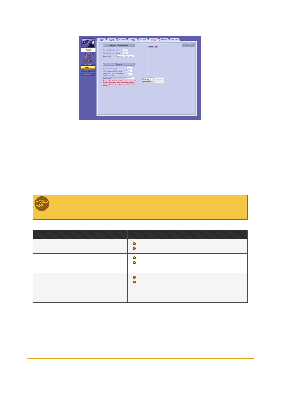
Figure 6-16 - Security & DP SW
1. In the Upload DataPass Permitted drop-down, select Yes. Once this feature has been enabled,
more options become available
2. In the Upload During Fueling drop-down, select whether to upgrade DataPass firmware only
during refueling or also when the vehicle arrives at the station
3. In the Upload Mode drop-down, select Any to upgrade any DataPass identified by the network or
Selected by Vehicle Code to upgrade predefined vehicles
4. If the latter was selected, click Add New Vehicle Code and enter the code in the table
5. Click Submit
Note: If the system is installed at a gas station, it's highly recommended to upgrade
DataPass units during refueling only to prevent overload.
Table 6-8 - Security & DP SW Elements
Element Descript ion
Uplo ad DataPass Permitted
Uplo ad Only During F uelin g
Uplo ad Mode
Yes: Allows remote upgrade of DataPassunits
No: disablesremote upgrade
Yes: Allows remote upgrade onlyduring refueling
No: Allowsremote upgrade as soon as the vehicle is identified
by the system
Any: Enables remote upgrade for any DataPass unit
Selected by Vehicle Co de: restricts remote upgrade to
specific vehicles. A unique Vehicle Code that represents the
make, model and year is assigned while programming the
DataPass units.
Fuel Point PLUS Station Equipment Manual 63
Page 64

Element Descript ion
Add New Vehicle Code Adds a text box to the Vehicle Code table
Remove Last Vehicle Code Removes the last entered vehicle code from the table
Enables/disables tamper resistant feature that prevents unau-
µWNR Removal Protection
Allow fueling while DP is missing
Disable search for DataPass if was not read at
first attempt
thorized removal. If disabled, µWNR units will not be deactivated also
if an attempt to remove the unit was made ( i.e. removal protection
ring was taken off)
Allowsfueling also when F uel Ring is correlated with DataPass,but
DP was not found by the network. If set to Yes the following two
options become available
If disabled, and DP unit was not found while µWNR is reading
the FP, the network will search again for the DP unit for 15
seconds and onlythen r efueling will start
If enabled, the network will not search again for the DP unit and
refueling will start automatically
Repo rted Odometer/E.H. Value if DP exist bu t
not found
Submit
Select the value to be reported for both Odometer and Engine Hour
parameters when DP was not found
Saves the settings of the current tab. To applythe changes, see Sav-
ing Setup
6.5.7. Log Level
In this tab (see Figure 6-17), you can set what type of information is gathered in logs and how to collect
these logs files, as it may be required for maintenance and troubleshooting purposes.
You will be able to receive these logs by connecting your PC to the Master Wireless Gateway via LAN,
using a terminal application (such as HyperTerminal).
64 Fuel Point PLUS Station Equipment Manual
Page 65

Figure 6-17 - Log Level
1. In the In the Debug Port Interface drop-down, select TCP/IP. The Debug Port field is auto-
populated with default port: 5000. There is no need to change this port
2.
Choose which logs you want to collect and the level of detail, by selecting the checkboxes in the
row of the log source (see Table 6-9):
Data: Only data sent
Debug: Additional debug info
3.
Select the logging level:
Info: Detailed logs
Error: Error logs only
4. Click Submit
Example:
The system keeps logs from all sources at error level, as a default. You may want to get
detailed data on VIT (Communication between Wireless Gateway and WNR) and on VIU
(Data on vehicle units received during refueling).
To do so, select Data, Debug and Info in both VIT and VIU rows.
Note: Log Events (Flash) section is currently not available.
Fuel Point PLUS Station Equipment Manual 65
Page 66

Table 6-9 - Log Sources
Source Information
TcpS Server communication with the FCC (Forecourt Controller)
TcpC Client communication with the FCC
VIT Communication between WirelessGateway and WNR
FCC Communication with the FCC
VISP RF communication between Master Wireless Gateway and the WirelessGateway units
DIAG Internal system diagnosis processes
AUTH Authorization processes
MAIN Internal system processes(written into Flash memory)
DataPass Communication with DataPass units
VIU Data on vehicle units received during refueling
LOG Logs and events
WEB Changes made to network using this Setup Site
COM0 COM0 device'sserial port
COM1 COM1 device'sserial port
CWGT Communication with the router
ADMIN
OrData Communication with OrData system
Administration tasks, station management, data distributed from Master WirelessGateway to the
WirelessGateway unis
6.5.8. Saving Setup
After finishing setting up the unit, click Apply on the Save Setup tab (see Figure 6-18)to save the
changes into the device's Flash memory.
Note: This step is essential! If this step is skipped, all settings will be lost, even if you
clicked on the Submit button on each tab.
66 Fuel Point PLUS Station Equipment Manual
Page 67

Figure 6-18 - Save Setup
From here you can also save the settings into an .XML file for reuse in similar stations.
1. Click Apply. The confirmation message below appears (see Figure 6-19)
Figure 6-19 - Flash Memory Confirmation Message
2. Click OK. A new message is displayed (see Figure 6-20)
Figure 6-20 - Reset Confirmation Message
Fuel Point PLUS Station Equipment Manual 67
Page 68

If changing settings of a working station, wait until the station is idle. The network can't be reset
while a vehicle is refueling (see Figure 6-21).
Figure 6-21 - Reset not Allowed while Fueling Warning
3. Click OK. The notification below will also be shown (see Figure 6-22)
Figure 6-22 - Page Reload Message
4. Click OK
6.5.8.1. Exporting Setup
1. Click Download Setup to PC. The message below appears (see Figure 6-23)
Figure 6-23 - Download Setup Confirmation Message
2. Click OK. A file download prompt appears. Click Save or click Save As to rename the .XML file, or
to select the location where you want to save your file
68 Fuel Point PLUS Station Equipment Manual
Page 69

Note: You may reuse these settings in other similar stations. See Setting Minimal
Setup.
6.6. Setting the Wireless Gateway Units
In order to establish the network, login into each Wireless Gateway unit deployed at the station, click
Setup and perform the following settings in the Minimal Setup tab (see Figure 6-24, Table 6-3).
Figure 6-24 - Minimal Setup - Wireless Gateway Units
1. In the Station ID field, enter the same ID used for the Master Wireless Gateway
2. In the Logical Address field, enter a unique address for the Wireless Gateway unit, between 3
and 254. Each Wireless Gateway must have a different logical address
3. (Optional) In the Location field, enter a descriptive free-text to easily identify the unit
4. In the Wireless Active Channels section, select the same channels used for Master Wireless
Gateway to establish the network
5. Click Submit
6. Optional: In the General Setup tab (see Figure 6-9), in the IP Address field, modify the factory set
IP address of the unit and then click Submit. For example, you may want to change the IP from
192.168.1.170 to 192.168.1.17X (to match the unit's logical address) so the next time you browse
to the unit locally (and not via Master Wireless Gateway), you will use this IP
7. Apply the changes, see Saving Setup
Fuel Point PLUS Station Equipment Manual 69
Page 70

After setting all the terminals, verify their link quality. See Viewing Wireless Gateway
Units Status. Link quality must be Excellent for all the units. Otherwise, the installation is
incorrect and should be checked (Master Wireless Gateway location, Wireless Gateway
units location).
Notes:
Station ID and Wireless Active Channels parameters must be identical for
Master Wireless Gateway and all Wireless Gateway units. See Setting
Minimal Setup
Logical Address must mach settings done in Master Wireless Gateway, while
associating µWNR to Wireless Gateways. See WNR Configuration List.
Note: When setting up a unit for the first time, you must always click Submit before
continuing to the next tab. If not, the following message appears (see ):
Figure 6-25 - Submit Button Warning
6.6.1. Updating Software Locally
You can locally update the software of a Wireless Gateway unit (see Figure 6-26).
70 Fuel Point PLUS Station Equipment Manual
Page 71

Figure 6-26 - Software Upload Screen
1. In the File Type drop-down, select the type of software component
2. Click on the Browse button on the bottom screen. A file selection dialog appears
3. (Optional) In the Force Upload drop-down, change default to YES to enforce uploading a version
older than the current version installed in the system.
Note: use this option only when a previous software version must be installed.
4. Select the file and click Upload. The file is uploaded to the Wireless Gateway
5.
Define how the execute the update. Select one of the following:
Update Immediate: The update is executed immediately after the component was
received by the Wireless Gateway
Update at Date & Time: The update is executed at a specific time. When this option
is selected, Update Time fields are displayed. Enter the update Date and Time
Update without Reset: Update is executed immediately, but new version takes effect
after the network is manually reset. See Saving Setup
Update at Admin Command (Manual): The update is executed only after reset is
manually initiated by the user. See Saving Setup
Best Practice: It is highly recommended to update all units remotely via Master Wireless
Gateway to ensure all units are synchronized with the same software versions. See
Updating Software.
Fuel Point PLUS Station Equipment Manual 71
Page 72

6.7. Viewing Network Status
You can monitor the status of all Wireless Network components in the station.
To open the Status Screen, click on the Status navigation button.
6.7.1. Monitoring Vehicle Units
The Fueling screen displays data on all vehicles equipped with DataPass units found within the station in
a table, for view only (see Figure 6-27, Table 6-10). It is automatically refreshed every 15 minutes.
Figure 6-27 - Status - Fueling Tab
72 Fuel Point PLUS Station Equipment Manual
Page 73

Table 6-10 - Fueling Status Table Elements
Parameter Descript ion
Vehicle ID Vehicle'splate number
Odometer Vehicle's odometer reading
Engine Ho ur Vehicle's engine hoursreading
Vehicle Code Unique Vehicle Code that represents make, model and year
FP Indicates whether a F uel Ring unit was detected or not
DataPass Ver DataPass curr ent version
FP/VIU T ag ID DataPass unit ID
Fueling Indicates whether the vehicle is currently fueling
PWireless Gateway
WNR Curr ently N/A
Expiration in
Table
Result N/A
Curr ently N/A
Remaining time in the network. A DataPass unitis considered active for 15 minutes since it was found by
the Network. After r efueling is completed, it is active for an extra two minutes.
6.7.2. Monitoring Alerts
The Alerts screen displays Wireless Network and authorization related alerts (see Figure 6-28) in a table,
for view only.
Figure 6-28 - Status - Alerts Tab
Fuel Point PLUS Station Equipment Manual 73
Page 74

This includes:
Date and time of the event
The type of device involved in the event
The Logical Address of the Wireless Gateway unit associated to the event
A brief description of the event
You can filter the data by date and time.
Do one of the following:
Select the Last X Days radio button and enter the number of days
Select the Time Range radio button and then enter the time range in the From and To fields
Select the All radio button to display all the alerts found without filtering
Click Submit to apply the filter.
6.7.3. Monitoring Station Equipment
The Wireless Gateway Map screen displays data on the station equipment: Master Wireless Gateway,
Wireless Gateway units and µWNR units in a hierarchical tree structure (see Figure 6-29, Table 6-11).
Figure 6-29 - Status - Wireless Gateway Map Tab
The status of each component is indicated by the color of the icon:
Green: Connected unit/µWNR battery is full
Red: Disconnected unit/µWNR battery is low
Grey: Deactivated µWNR unit
74 Fuel Point PLUS Station Equipment Manual
Page 75

Table 6-11 - Wireless Gateway Map Parameters
Parameter Descript ion
Master Wireless Gateway/Wireless Gateway
Add r LogicalAddress
Location Unit'slocation
SW Software version
HW Rev Hardware revision
µWNR
Pump Number of the pump to which the unit isassociated
Nozzle Number of the nozzle on which the unit is installed
SW Software version
Fueling Indicates whether the vehicle is currently fueling
HW Rev Hardware revision
Last Activity Date and time of last r ecorded activity
Batt ery Status Percentage of batter y life r emaining
S/N Unit'sserialnumber
6.7.4. Reactivating WNR Units Via Setup Site
The µWNR units include a tamper resistant feature that prevents unauthorized removal, deactivating the
unit whenever an attempt is made. See more in Reactivating µWNR Units
Deactivated µWNR units can be remotely reactivated from this screen (see Figure 6-30, Table 6-12).
Fuel Point PLUS Station Equipment Manual 75
Page 76
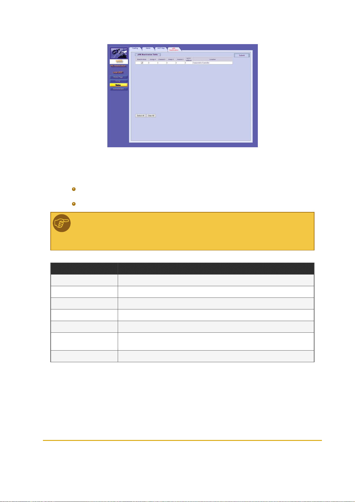
Figure 6-30 - Status - µWNR Reactivation
Do one of the following:
To reactivate a specific µWNR: In the Reactivation column, select the checkbox in the
corresponding row and then click Submit
To reactivate all deactivated units: Click Select All and then click Submit
Note: When reactivating the µWNR unit from the Setup Site, the unit becomes fully
functional after next fueling. Simulate refueling (tilt the unit and attach to a Fuel Ring) to
apply reactivation.
Table 6-12 - Reactivation Table Fields
Field Descript ion
Reactivation Select this checkbox to reactivate the unit
Group# Unit's group (for communication with Station Controller)
Chan nel# Logicalchannel for communication with the controller
Pump# Number of the pump to which the unit is associated
Nozzle# Number of the nozzle on which the unit is installed
Wireless Gateway
Add ress
Location WirelessGateway's location
Logicaladdress of the Wireless Gateway to which the µWNR is routed
76 Fuel Point PLUS Station Equipment Manual
Page 77

6.8. Performing Administrator Tasks
You can remotely manage all Wireless Network components in the station.
Note: Log Download feature is currently N/A.
To open the Administrator Screen, click on the Administrator navigation button.
6.8.1. Viewing Wireless Gateway Units Status
The Wireless Gateway Map screen in the Administrator section displays a table of the Wireless Gateway
units connected in the station (see Figure 6-31, Table 6-13). You can do the following:
View the status and the link quality of each Wireless Gateway unit in the network
Rebuild the table to get an updated picture (i.e. when Wireless Gateway units were replaced)
Figure 6-31 - Administrator - Wireless Gateway Map Tab
Fuel Point PLUS Station Equipment Manual 77
Page 78

Table 6-13 - Wireless Gateway Map Table Parameters
Parameter Descript ion
Select Select this checkbox in the corresponding row to choose the Wireless Gateway unit
Logical Num Unit's logical address
WGT Type WirelessGateway/Master Wireless Gateway
Location Unit'slocation
Last Activity Date and time of last recorded activity
Link Quality Signal strength
Statu s Unit status: Active/Inactive/Pending
6.8.1.1. Rebuilding Tables
1. First, clear the existing table: click Select All and then Remove Selected
2. Click Rebuild Table. A confirmation message appears (see Figure 6-32)
Figure 6-32 - Table Rebuilding Confirmation Message
3. Click OK
4.
Refresh the page, by clicking on the Wireless Gateway Map tab
Note: You can manually remove a Wireless Gateway from the table: select the unit and
then click Remove Selected.
Note: The network can't be rebuilt while a vehicle is refueling (see Figure 6-33).
78 Fuel Point PLUS Station Equipment Manual
Page 79

Figure 6-33 - Table Rebuilding not Allowed while Fueling Warning
6.8.2. Updating Software
You can remotely update the software of all station equipment from the Master Wireless Gateway and
view a list of currently installed and stored software components (see Figure 6-34, Table 6-14)
Figure 6-34 - Administrator - Software Distribute Tab
6.8.2.1. Software Update Workflow
Software version is uploaded to the Master Wireless Gateway and saved in its Flash memory
(Status: In Progress)
The Master Wireless Gateway then sends this version to the other Wireless Gateway units.
The new version is stored in each Wireless Gateway memory. At this stage the status can be:
Pending
Inactive: S/W version does not match the Wireless Gateway type, or is older than
the current version. Updates in Inactive status will not be executed
Update is executed. New version takes effect after update is finished and the network is reset
(Status: Complete)
6.8.2.2. Updating Software Components
Fuel Point PLUS Station Equipment Manual 79
Page 80

1. In the File Type drop-down, select the type of software component
2. Click on the Browse button on the bottom screen. A file selection dialog appears
3. (Optional) In the Force Upload drop-down, change default to YES to enforce uploading a version
older than the current version installed in the system.
Note: use this option only when a previous software version must be installed.
4. Select the file and click Upload. The file is uploaded to the Master Wireless Gateway
5.
(Optional) You can schedule when the Master Wireless Gateway sends the uploaded version to the
Wireless Gateway units in the network during the day (otherwise the component is immediately
sent). To do so:
a. Select the Distribute at time range checkbox. Time range fields are displayed
b. Enter the start and end hour in the From Time and Until Time fields
6.
Define how the execute the update. Select one of the following:
Update Immediate: The update is executed immediately after the component was
received by the Wireless Gateway
Update at Date & Time: The update is executed at a specific time. When this option
is selected, Update Time fields are displayed. Enter the update Date and Time
Update at Admin Command: The update is executed only after all the Wireless
Gateway units received the component. When this option is selected, additional
options appear:
Automatic: When this option is selected, the network is automatically reset
Manual: (default). Reset is manually initiated by the user by clicking Send
Update without Reset: Update is executed immediately, but new version takes effect
after the network is manually reset. See Saving Setup
Best Practice: It is highly recommended to use Update at Admin Command - Manual.
Verify that the status off all the units in the table is Pending and it remains so for about 10
minutes and then reset the network (by clicking Send). Please remind that the network
can only be reset when the station is idle (there is no refueling).
80 Fuel Point PLUS Station Equipment Manual
Page 81

Table 6-14 - Wireless Gateway Station Map Table Parameters
Colu mn Description
Logical Num
Entit y Type
Family
HW Version Unit's har dware version
SW Version Currentlyrunning software version
New SW Version Stored software version
Upd ate Option Selected Update option ( see Step 6)
Statu s Software update status: In Progress → Pending → Complete
6.8.2.2.1. Rebuilding Tables
Unit's logical address. Clickon the plus sign at the left side to expand and view the software components included in the unit
Unit type: Master WirelessGateway (Master Wireless Gateway) or WirelessGateway and the software components included in the unit
Hardware versionsare grouped into Families. Software versionscan be installed on specifichardware families. When a new version is uploaded, it will activated only in unitsthat pertain to the proper
family
You can rebuild the Wireless Gateway Station Map table to get an updated picture of the status of the
units
1. Click Rebuild Table. A confirmation message appears (see Figure 6-35)
Figure 6-35 - Table Rebuilding Confirmation Message
2. Click OK
3.
Refresh the page, by clicking on the Software Distribute tab
Note: The network can't be rebuilt while a vehicle is refueling (see Figure 6-36).
Fuel Point PLUS Station Equipment Manual 81
Page 82

Figure 6-36 - Table Rebuilding not Allowed while Fueling Warning
6.8.3. Importing Network Settings
You can import previously saved setup files and then send them to all the units at the station remotely
from the Master Wireless Gateway(see Figure 6-37, Table 6-15).
The setup files are first uploaded to the Master Wireless Gateway and then sent to the other Wireless
Gateway units. Setup takes effect after update is finished and the network is reset (Status: Complete)
Figure 6-37 - Administrator - Setup Distribute Tab
1. Click on the Browse button the in the unit row. A file selection dialog appears
2. Select the previously saved .XML file and click Upload. The file is uploaded to the Master Wireless
Gateway
3.
Repeat these steps for every unit you want to remotely set up
4.
In the Select column, select the checkbox in the corresponding row or click Select All to select all
the units
5.
Define how the execute the update. Select one of the following:
Update Immediate: The update is executed immediately after the file was received by
the Wireless Gateway
82 Fuel Point PLUS Station Equipment Manual
Page 83

Update at Date & Time: The update is executed at a specific time. When this option
is selected, Update Time fields are displayed. Enter the update Date and Time
Update at Admin Command: The update is executed only after all the Wireless
Gateway units received the files. When this option is selected, additional options
appear:
Automatic: When this option is selected, the network is automatically reset
Manual: (default). Reset is manually initiated by the user by clicking Send
Update without Reset: Update is executed immediately, but new setup takes effect
after the network is manually reset. See Saving Setup
6. Click Distribute Setup Files
Best Practice: It is highly recommended to use Update at Admin Command - Manual.
Verify that the status off all the units in the table is Pending and it remains so for about 10
minutes and then reset the network (by clicking Send). Please remind that the network
can only be reset when the station is idle (there is no refueling).
Table 6-15 - Wireless Gateway Station Map Table Parameters
Colu mn Descriptio n
Select Selectsthe unit
Logical Num Unit'slogical address
Wireless Gateway Type Unit type: Master WirelessGateway (Master Wireless Gateway) or WirelessGateway
Location Wireless Gateway's location
Setup File Selectsthe .XML setup file
Statu s Setup update status: In Progress → Pending → Complete
6.8.3.1. Rebuilding Tables
See Rebuilding Tables
6.8.4. Exporting Network Settings
You can connect to MWGT and export setup files from Master Wireless Gateway and Wireless Gateway
units to reuse in other similar stations. See Importing Network Settings.(See Figure 6-38, Table 6-16).
Fuel Point PLUS Station Equipment Manual 83
Page 84

Figure 6-38 - Administrator - Setup Download Tab
1. In the Select column, select the checkbox in the corresponding row or click Select All to select all
the unit
2. Click on ellipsis button (...) next to the Get Folder field to select a destination folder
3. Click Download Setup Files From Station Devices
Table 6-16 - Wireless Gateway Station Map Table Parameters
Colu mn Descriptio n
Select Selectsthe unit
Logical Num Unit's logicaladdress
Wireless Gateway Type Unit type: Master WirelessGateway (Master Wireless Gateway) or Wireless Gateway
HW Version Unit'shardware version
Location WirelessGateway's location
Activity Date and time of last recorded activity
Last Keep Alive Response Last Keep Alive check reply sent bythe unit
Statu s Download status: Completed or Error
6.8.4.1. Rebuilding Tables
See Rebuilding Tables
84 Fuel Point PLUS Station Equipment Manual
Page 85

6.8.5. Managing Stored Firmware
You can view a list of software versions stored in the Master Wireless Gateway Flash memory and clean
the memory if necessary. (see Figure 6-39)
Figure 6-39 - Administrator - Firmware Storage Tab
The Wireless Gateway Station Map in the upper part of the screen displays:
File Type
SW Version
Family
Upload Options
To clean the memory, click Clear Storage.
Fuel Point PLUS Station Equipment Manual 85
Page 86

Page 87

CHAPTER 7 PROGRAMMING WNR UNITS
7.1. General
This chapter provides instructions for programming µWNR units
To program the µWNR units, you simply need to set three parameters:
Station ID
Pump #
Nozzle #
Note: Station ID, Pump# and Nozzle# must mach the settings done in Master Wireless
Gateway. See WNR Configuration List
7.2. Required Tools
To program µWNR units you may use one of the following tools:
Wireless Nozzle Reader Programmer, for retail stations (see Figure 7-1)
Fuel Point PLUS Station Equipment Manual 87
Page 88

Figure 7-1 - Wireless Nozzle Reader Programmer
Wireless Vehicle Programmer, for home-base stations (see Figure 7-2)
Figure 7-2 - Wireless Vehicle Programmer
88 Fuel Point PLUS Station Equipment Manual
Page 89

7.3. Programming µWNR - Home Base Stations
Turn on the programmer and follow the instructions that appear on the display, described below (see
Table 7-1). Use the ENTER key to select options and advance to next screen.
Fuel Point PLUS Station Equipment Manual 89
Page 90
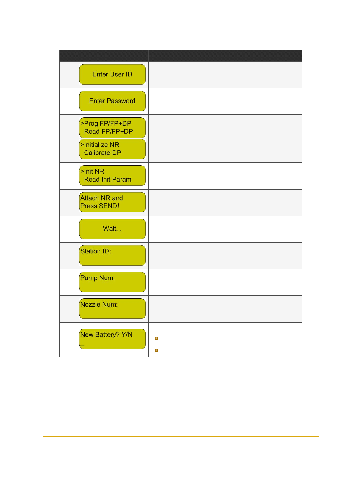
Table 7-1 - µWNR Programming Sequence - Home Base Stations
Step Display Descriptio n
1 Enter user name
2 Enter password
3
4 Select the Init NR option
5
6 Wait a few seconds until the Programmer recognizesthe unit
7 Enter the Station ID as set in Master Wireless Gateway
8 Enter the number of the pump asset in Master Wireless Gateway
9
The main menu is displayed. Use the UP/DOWN arrow keysto select Initialize NR
Sway the µWNR (or press the µWNR-T activation switch) and attach to
the rear cover of the Programmer. Press SEND
Enter the number of the nozzle on which the unit is installed as set in
Master Wireless Gateway
Do one o f the following:
10
Press Y for a brand new unit, or for a reprogr ammed unit after
battery replacement
Press N if the unit is reprogrammed but the battery wasn't replaced
90 Fuel Point PLUS Station Equipment Manual
Page 91

Step Display Descriptio n
11 Verify that all the parameters are correct and press SEND
12
13 A successmessage is displayed
Sway the µWNR (or press the µWNR-T activation switch) and attach to
the rear cover of the Programmer.
7.4. Programming µWNR - Retail Stations
Turn on the programmer and follow the instructions that appear on the display, described below (see
Table 7-2). Use the ENTER key to select options and advance to next screen.
Fuel Point PLUS Station Equipment Manual 91
Page 92

Table 7-2 - µWNRProgramming Sequence - Retail Stations
Step Display Descriptio n
1 The main menu is displayed. Select the T48 Functions option
2 Select the Prog VIS NR option
3 Enter the Station ID as set in Master Wireless Gateway
4 Enter the number of the pump asset in Master Wireless Gateway
5
6
7 Wait a few seconds
8 A successmessage is displayed. PressA to return to the main menu
Enter the number of the nozzle on which the unit is installed as set in
Master Wireless Gateway
Verify that all the parameters are correct. Sway the µWNR (or press the
µWNR-T activation switch), attach the unit to the programming coil and
press SEND
7.5. Reactivating µWNR Units
The µWNR units include a tamper resistant feature that prevents unauthorized removal, deactivating the
unit whenever an attempt is made.
7.5.1. Causes Of Deactivation
There are two possible triggers that can cause the units to enter into deactivation mode:
An attempt to remove µWNR-F from the nozzle occurred: Removal Protection ring was taken
off, disconnecting activation wires
92 Fuel Point PLUS Station Equipment Manual
Page 93

Battery was removed/battery is fully drained
Once a unit is deactivated,you'll be notified as follows:
In Status → Alerts screen (see Monitoring Alerts)
In Status → WGT Map screen, the µWNR is colored in gray (see Monitoring Station
Equipment)
The µWNR LED indicator blinks three times when the unit is swayed
7.5.2. Reactivation Methods
There are three ways to reactivate µWNR units:
Using the Station Manager Tag:
1.
Attach the Station Manager Tag to the deactivated unit
2.
Tilt the unit to ensure it wakes up. The LED indicates that the unit is blocked, blinking three times
3.
The Station Manager Tag reactivates the unit. The unit becomes operational and the LED blinks
twice (as it is reactivated and the tag was recognized)
Sending a reactivation command from the Setup Site. See Reactivating WNR Units via
Setup Site
Note: When reactivating the µWNR unit from the Setup Site, the unit becomes fully
functional after next fueling. Simulate refueling (tilt the unit and attach to a Fuel Ring) to
apply reactivation.
Reprogramming the µWNR (setting Station ID, Pump#, Nozzle# anew) using the Wireless
Vehicle Programmer or the Wireless Nozzle Reader Programmer. See Programming WNR
Units
Fuel Point PLUS Station Equipment Manual 93
Page 94

Page 95

CHAPTER 8 SETTING THE STATION
CONTROLLER
8.1. General
This chapter describes the settings required to configure the communication interface between the
Controller and the Master Wireless Gateway, when using Fuel Point PLUS system with Gasboy's
SiteOmat Station Controller.
The process consists of three main steps:
1.
Defining the Master Wireless Gateway - Station Controller communication channel
2.
Defining the Master Wireless Gateway in the system
3.
Assigning µWNR to the nozzles
Note: In cases where other FCC/POS applications are used, please refer to the
manufacturer's instructions.
Note: If the station is equipped with more than 16 µWNR units (more than one group, see
Setting Group Communication) you will need to create a communication channel for
each group with the correct Port# and then define a virtual Master Wireless Gateway (.i.e.
Master Wireless Gateway2, Master Wireless Gateway3) that uses this bus.
Note: The settings below maybe also done when setting up SiteOmat application using
the Setup Wizard. For further information, please refer to SiteOmat Station Controller
Setup and Maintenance Manual.
8.2. Getting Started
1. Log in to SiteOmat application as Administrator. The following screen is displayed (see Figure 8-1).
Fuel Point PLUS Station Equipment Manual 95
Page 96

Figure 8-1 - SiteOmatPumps Status Screen
2. Click on the Setup navigation button. The following screen is displayed (see Figure 8-2).
Figure 8-2 - Setup - Basic Mode Screen
3. Click Advance Mode. The Advanced Setup screen is displayed (see Figure 8-3).
96 Fuel Point PLUS Station Equipment Manual
Page 97

Figure 8-3 - Advanced Setup Screen
8.3. Setting the Communication Channel
1. Select the Buses tab. The Buses dialog box appears (see Figure 8-4). In this dialog you can define
or update existing communication channels that transport data to/from the peripheral devices
Figure 8-4 - Buses Dialog Box
Fuel Point PLUS Station Equipment Manual 97
Page 98

2. In the Name field, enter a name to identify the bus (.i.e. Master Wireless Gateway)
3. In the Frame drop-down, select Orpak
4. Select the TCP/IP radio button
5. In the IP field, enter the Master Wireless Gateway IP address. Default IP is 192.168.1.170.It can
be changed in Master Wireless Gateway Setup Site, see General Setup
6. In the Port field, enter port number (between 3000 and 4000). It must match the TCP/IP Port
defined in Master Wireless Gateway Setup Site, see Setting Group Communication
7. Click New. The new bus is added to the grid at the top of the dialog
8. Click Close
8.4. Setting the Master Wireless Gateway
1. Select the VIS (Vehicle Identification System) tab. The VIS dialog box appears (see Figure 8-5).
Figure 8-5 - VIS Dialog Box
2. In the Name field, enter a name to identify the unit
3. In the Bus drop-down, select the bus you've created before
4. In the Model drop-down, select Wireless Gateway
5. In the Address section, select the HEX radio button and then enter the RS-485 address of the
group (between 31 and 39). It must match the Group Address defined in Master Wireless
Gateway Setup Site, see Setting Group Communication
6. Click New. The new item is added to the grid at the top of the dialog
7. Click Close
98 Fuel Point PLUS Station Equipment Manual
Page 99

8.5. Assigning Channels to Nozzles and Applying Changes
1. In the Setup Screen (see Figure 8-6), in the Channel drop-down, select a channel (1 to 16 as set in
Master Wireless Gateway Setup site, see WNR Configuration List) to associate the µWNR to
the nozzle
Figure 8-6 - Advanced Setup Screen
2. Click Save
3. Click Reload
Fuel Point PLUS Station Equipment Manual 99
Page 100

 Loading...