

Page 1

Fuel Point® System
Ground Antenna Installation
Instructions
MDE-4530
(formerly C35982)
Page 2

Computer Programs and Documentation
Federal Communications Commission (FCC) Warning
All Gasboy computer programs (including software on diskettes and within memory chips) and documentation are copyrighted by, and shall remain the property of, Gasboy. Such
computer programs and documents may also contain trade secret information. The duplication, disclosure, modification, or unauthorized use of computer programs or
documentation is strictly prohibited, unless otherwise licensed by Gasboy.
This equipment has been tested and found to comply with the limits for a Class A digital device pursuant to Part 15 of the FCC Rules. These limits are designed to provide
reasonable protection against harmful interference when the equipment is operated in a commercial environment. This equipment generates, uses, and can radiate radio frequency
energy, and if not installed and used in accordance with the instruction manual, may cause harmful interference to radio communications. Operation of this equipment in a
residential area is likely to cause harmful interference in which case the user will be required to correct the interference at his own expense. Changes or modifications not expressly
approved by the manufacturer could void the user’s authority to operate this equipment.
Approvals
Gasboy, Greensboro, is an ISO 9001:2000 registered facility.
Underwriters Laboratories (UL):
UL File# Products listed with UL
MH4314
MH6418
MH7404
MH10581 Key control unit, Model GKE-B Series
All dispensers and self-contained pumping
units
Power operated Transfer Pump Models 25,
25C, 26, 27, 28, 72, 72S, 72SP, 72X, 73 and
1820
Hand operated Transfer Pump Models 1230
Series, 1243 Series, 1520 and 1720 Series
Card reader terminals, Models 1000, 1000P
Site controller, Model 2000S CFN Series
Data entry terminals, Model TPK-900 Series
Fuel Point Reader System
New York City Fire Department (NYFD):
NYFD C of A # Product
4823 9100A, 9140A, 9152A, 9153A,
4997 9822A, 9823A
5046 9100Q, 9140Q, 9152Q, 9153Q,
9800A, 9840A, 9850A, 9852A,
9853A, 9140
9800Q, 9840Q, 9852Q, 9853Q
National Conference of Weights and Measures (NCWM) - Certificate of Compliance (CoC):
Gasboy pumps and dispensers are evaluated by NCWM under the National Type Evaluation Program (NTEP). NCWM has issued the following CoC:
CoC# Product Model # CoC# Product Model # CoC# Product Model #
95-179A2 Dispenser
95-136A5 Dispenser 9800 Series 91-057A3 Controller
9100 Retail Series, 8700
Series, 9700 Series
91-019A2 Dispenser
9100 Commercial
Series
1000 Series FMS,
2000S-CFN Series
California Air Resources Board (CARB):
Executive Order # Product
G-70-52-AM Balance Vapor Recovery
G-70-150-AE VaporVac
Patents
Gasboy products are manufactured or sold under one or more of the following US patents:
Dispensers
5,257,720
Point of Sale/Back Office Equipment
D335,673
Trademarks
Non-registered trademarks
Atlas™
Consola™
Infinity™
Registered trademarks
ASTRA
Fuel Point
Gasboy
Keytrol
Slimline
Additional US and foreign patents pending.
®
®
®
®
®
Additional US and foreign trademarks pending.
Other brand or product names shown may be
trademarks or registered trademarks of their
respective holders.
This document is subject to change without notice. · For information regarding Gasboy Literature, call (336) 547-5661
E-mail: literature@gasboy.com · Internet: http://www.gasboy.com
© 2005 GASBOY · All Rights Reserved
Page 3

Table of Contents
Table of Contents
1 – Introduction . . . . . . . . . . . . . . . . . . . . . . . . . . . . . . . . . . . . . . . . . . . . . . . . . . . . . . 1
Purpose . . . . . . . . . . . . . . . . . . . . . . . . . . . . . . . . . . . . . . . . . . . . . . . . . . . . . . . . . . . . . . . . . . . . . . . . . . 1
Intended Users . . . . . . . . . . . . . . . . . . . . . . . . . . . . . . . . . . . . . . . . . . . . . . . . . . . . . . . . . . . . . . . . . . . . 1
Related Reading . . . . . . . . . . . . . . . . . . . . . . . . . . . . . . . . . . . . . . . . . . . . . . . . . . . . . . . . . . . . . . . . . . . 1
Abbreviations and Acronyms. . . . . . . . . . . . . . . . . . . . . . . . . . . . . . . . . . . . . . . . . . . . . . . . . . . . . . . . . . 2
Warranty . . . . . . . . . . . . . . . . . . . . . . . . . . . . . . . . . . . . . . . . . . . . . . . . . . . . . . . . . . . . . . . . . . . . . . . . . 2
System Overview. . . . . . . . . . . . . . . . . . . . . . . . . . . . . . . . . . . . . . . . . . . . . . . . . . . . . . . . . . . . . . . . . . . 3
Ground Loop Communications - General Information. . . . . . . . . . . . . . . . . . . . . . . . . . . . . . . . . . . . . . . 4
Ground Antenna System Layout . . . . . . . . . . . . . . . . . . . . . . . . . . . . . . . . . . . . . . . . . . . . . . . . . . . . . . . 4
Fueling a Vehicle Using Fuel Point
Authorizing a Gate Opening Using Fuel Point Gate Antenna System . . . .6
Fuel Point Gate Parameters. . . . . . . . . . . . . . . . . . . . . . . . . . . . . . . . . . . . 6
2 – Component Overview . . . . . . . . . . . . . . . . . . . . . . . . . . . . . . . . . . . . . . . . . . . . . . 7
Required Components. . . . . . . . . . . . . . . . . . . . . . . . . . . . . . . . . . . . . . . . . . . . . . . . . . . . . . . . . . . . . . . 7
Fueling With a Ground Antenna . . . . . . . . . . . . . . . . . . . . . . . . . . . . . . . . . 7
Gate Feature Using a Ground Antenna . . . . . . . . . . . . . . . . . . . . . . . . . . . 7
Additional Fuel Point Gate Site Components. . . . . . . . . . . . . . . . . . . . . . . 7
Fuel Point Gate Vehicle Components . . . . . . . . . . . . . . . . . . . . . . . . . . . .8
®
Ground Antenna System . . . . . . . . .4
3 – Installation . . . . . . . . . . . . . . . . . . . . . . . . . . . . . . . . . . . . . . . . . . . . . . . . . . . . . . . 9
Important Vehicle Parameters – Read Before Proceeding . . . . . . . . . . . . . . . . . . . . . . . . . . . . . . . . . . . 9
Antenna Parameters for Opening a Gate with Fuel Point Ground Loop
Communications . . . . . . . . . . . . . . . . . . . . . . . . . . . . . . . . . . . . . . . . . . . . 9
Antenna Parameters for Fueling with Fuel Point Ground Loop
Communications . . . . . . . . . . . . . . . . . . . . . . . . . . . . . . . . . . . . . . . . . . . 10
Installing A Fuel Point Ground Antenna For Fueling . . . . . . . . . . . . . . . . . . . . . . . . . . . . . . . . . . . . . . . 13
C09822 Junction Box . . . . . . . . . . . . . . . . . . . . . . . . . . . . . . . . . . . . . . . . . . . . . . . . . . . . . . . . . . . . . .13
For Installing a Flush-mount J-Box Antenna . . . . . . . . . . . . . . . . . . . . . . 13
C09716 Antenna Sealant . . . . . . . . . . . . . . . . . . . . . . . . . . . . . . . . . . . . . . . . . . . . . . . . . . . . . . . . . . . 14
For Installing a Direct Buried and Sealed Antenna . . . . . . . . . . . . . . . . . 14
C07364 Surface Mount Antenna Installation. . . . . . . . . . . . . . . . . . . . . . . . . . . . . . . . . . . . . . . . . . . . . 15
Ground Antenna Used for Gate Control . . . . . . . . . . . . . . . . . . . . . . . . . . . . . . . . . . . . . . . . . . . . . . . . 16
Locating and Installing the Fuel Point Ground Antenna . . . . . . . . . . . . . . 16
MDE-4530 Fuel Point Ground Antenna Installation Instructions · November 2005 Page i
Page 4

Table of Contents
This page is intentionally left blank.
Page ii MDE-4530 Fuel Point Ground Antenna Installation Instructions · November 2005
Page 5

Purpose Introduction
1 – Introduction
Purpose
The Gasboy Fuel Point Ground Antenna Installation Manual is provided to assist you in
installing the ground loop communications ground antenna for the Fuel Point
manual should be supplied to the installer prior to installation to ensure that your components
are installed properly. Faulty installations are the major cause of system malfunctions. The
system components must be installed as described in this manual to ensure the reliability and
proper operation of the system. Read this entire manual before starting installation.
Gasboy provides a toll-free number for customers and installers having any questions
pertaining to the installation: 1-800-444-5529.
®
system. This
Intended Users
This manual provides information for Authorized Service Contractors (ASCs) or Customer
Service Contractors (CSCs) to install the Fuel Point Ground Antenna.
Related Reading
The following documents contain related information and may be helpful when using this
manual:
Document Number Title GOLD Library
C35628 FPR Installation Manual Gasboy Fuel Management Products
C35699 Vehicle Module Installation Manual Gasboy Fuel Management Products
MDE-4530 Fuel Point Ground Antenna Installation Instructions · November 2005 Page 1
Page 6

Introduction Abbreviations and Acronyms
Abbreviations and Acronyms
The following table contains a list of abbreviations and acronyms used in this manual.
Abbreviation/
Acronym
ASC Authorized Service Contractor
CFN Cash Flow Network
CSC Customer Service Contractor
FMS Fuel Management System
FPR Fuel Point Reader
OTR Over The Road
PCB Printed Circuit Board
VM Vehicle Module
Definition
Warranty
For information on warranty, refer to Gasboy’s Warranty Policy Statement - MDE-4255. If
you have any warranty-related questions, contact Gasboy’s Warranty Department at its
Greensboro location.
Page 2 MDE-4530 Fuel Point Ground Antenna Installation Instructions · November 2005
Page 7
Introduction System Overview
System Overview
Fuel Point adapts to listed Gasboy Fuel Management Systems (FMSs) for hassle-free fueling.
System applications determine actual components required. Your system may consist of
several or all of the following components:
• A Gasboy FMS (listed models 1000, 1000P-Series 1000 with Receipt Printer, or 2000S
CFN)
• Fuel Point Reader (FPR)
• For hose wire communications: pumps/dispensers modified using Listed Dispenser and
Hose Retrofit Kits, I/S Pre-Amp and vehicles equipped with Vehicle Modules (VM) and
T-Rings installed on fuel collars
• For Ground Loop Communications: a ground antenna, an I/S Pre-Amp. and vehicles
equipped with VMs with G-Ring inputs and G-Rings installed underneath
Figure 1-1 Fueling with Ground Antenna
Page 3 MDE-4530 Fuel Point Ground Antenna Installation Instructions · November 2005
Page 8

Introduction Ground Loop Communications - General Information
Ground Loop Communications - General Information
A Gasboy FMS equipped with an FPR can be configured to authorize a vehicle for fueling or
for opening a gate using ground loop communications. See C35628 FPR Installation Manual
for additional details.
Fueling with Ground Loop Communication is available with a Gasboy CFN system only.
Ground Loop Communications requires a ground antenna installed in or on the pavement at
the fueling island or gate location. There are three installation options for ground antennas to
meet a variety of site requirements:
• Flush-Mount J-Box
• Direct Buried and Sealed
• Surface Mounted
Vehicles are equipped with a special VM containing Ground Loop Communications circuitry
(C09668). In addition, a G-Ring is attached under the vehicle. For gate applications using
Hose Wire communications, the G-Ring is installed in addition to the T-Ring antenna attached
at the fuel tank opening. See C35699 Vehicle Module Installation Manual for VM and vehicle
antenna ring installation details.
Ground Antenna System Layout
When a Fuel Point-equipped vehicle G-Ring is over or near the ground antenna, the vehicle’s
ID is communicated to the FPR and, if authorized, the pump will automatically be made
available to fuel. The vehicle-to-FPR communications must be maintained during the entire
fueling operation. When the vehicle drives out of the communications range, the pump is shut
off and returned to an idle state, ready for a new transaction. The fueling event is logged and
relevant data stored by the FMS unit.
Fueling a Vehicle Using Fuel Point Ground Antenna System
IMPORTANT INFORMATION
Successful installation requires the special Fuel Point ground antenna
manufactured by Gasboy and careful attention to the instructions that
follow. Do not try to use the loop detector supplied with the gate
controller or the manufacturer’s entrance loop instructions.
To fuel using the Gasboy ground loop communications system, the site should meet certain
criteria. The following parameters must be considered:
• Each hose outlet (nozzle position) must be dedicated to only one lane. Lane-oriented
pumping units are recommended (such as Gasboy 9800A and 215A/216A Satellites with
suffix Z or equal).
• One ground antenna per hose outlet.
• Ground antennas are normally aligned with the nozzle position (when stored or hung up).
Page 4 MDE-4530 Fuel Point Ground Antenna Installation Instructions · November 2005
Page 9

Introduction Ground Antenna System Layout
This is the natural alignment for fueling; so drivers will not require special training.
• Other locations (other than aligned with nozzle) are acceptable but should be
supplemented with a sign or other visual aid like a line painted on pavement.
• The ground antenna is a 6 inches diameter molded ring. Read radius for vehicles is 20
inches to 48 inches, dependent on the type of vehicle being fueled. The closer the vehicle
ring or antenna is above the ground antenna, the greater the read zone.
G-Ring Height
Above Pavement
12” 48” Cars, Small Vans and Trucks
18” 30” Transit Buses, OTR Trucks
24” 24” School Buses
30” 20” Large Vehicles
Effective Communications
(Read Radius) Typical Vehicle Types for this range
• It is important for vehicle G-Rings to be centered over the ground antenna. When lanes are
not clearly defined, provision should be made to ensure that vehicles stop to fuel with the
vehicle over the center of the ground antenna (spaced at a proper distance from the pump).
A painted center line or traffic control devices (traffic cones) can be used to funnel
vehicles to the pump at the proper spacing.
• In applications with more than one dispenser per lane, the ground antennas must be
located so that the effective read diameters do not overlap. Spacing the ground antenna
(spacing pumps) at a distance of 10’ center-to-center will ensure proper operation. Refer
the chart about this spacing aspect on
“G-Ring Height” on page 5.
• Normally, vehicles should approach the pump to fuel from the same direction. For
applications where the fill tube varies from side to side, it is important to locate the ground
antenna in the center of the fueling lane and to locate the vehicle G-Rings at or very close
to the center of the vehicle (side to side).
Figure 1-2 Gate Installation (Typical)
Page 5 MDE-4530 Fuel Point Ground Antenna Installation Instructions · November 2005
Page 10

Introduction Ground Antenna System Layout
Authorizing a Gate Opening Using Fuel Point Gate Antenna System
The gate controller is a separately purchased device and is not part of the Fuel Point System. It
is configured to be opened from a relay closure provided by a Fuel Point-equipped FMS.
Gates vary greatly, depending on the brand and model. During the overall system design,
please review the following operational procedures with an authorized representative of the
gate manufacturer.
The standard gate opening switch or detector normally used is replaced by the Fuel Point Gate
System. The triggering device is replaced by a Fuel Point Ground Antenna that operates with a
Fuel Point-equipped vehicle.
Fuel Point Gate Parameters
When a Fuel Point gate-equipped vehicle is over the ground antenna (or traveling over the
ground antenna at a speed not exceeding 5 MPH) the VM number and system ID are read by
the Fuel Point system via the G-Ring and ground antenna installed in the pavement.
Authorization generally requires 3-4 seconds. If the vehicle is authorized to enter the site, the
system sends a relay closure to the gate controller, logs the event and stores the data. The gate
controller controls the opening and closing of the gate.
Note: Fuel Point-equipped vehicles traveling in excess of 15 MPH or faster will not be
authorized.
Page 6 MDE-4530 Fuel Point Ground Antenna Installation Instructions · November 2005
Page 11

Required Components Component Overview
2 – Component Overview
Required Components
System components vary depending upon the type of installation you are establishing:
Fueling With a Ground Antenna
The following system components are required for fueling with a Fuel Point ground antenna:
• A CFN system configured for ground loop communications
•FPR
• Fuel island ground antenna and vehicle with VM and G-Ring
Gate Feature Using a Ground Antenna
The following system components are required for the Fuel Point ground antenna gate feature:
• A dedicated CFN system with Gate Relay Control PCB or using the fuel island reader and
a relay in a PCU dedicated to opening a gate
~OR~
A Fleetkey system as a dedicated gate reader, programmed for gate
•FPR
• Gate Opening Ground Antenna and Vehicle with VM and G-Ring
The additional system components required for the operation of the Fuel Point as both a
fueling and a gate system are listed below.
Additional Fuel Point Gate Site Components
• Ground Antenna Kit (C07362) consisting of 6 inches molded antenna, lead-in cable and
connectors. You need one antenna per hose location. The antenna kit is installed using one
of the following optional components:
Figure 2-1 Ground Antenna Kit
•For Flush-Mount J-Box application, use Flush Mount Antenna Kit (C09822). This is
normally used at new sites where major reconstruction is anticipated to the pavement. The
antenna can be installed or poured in place and conduit run to the FPR location. Kit
includes a 6 inches x 8 inches x 6 inches deep composite plastic weather-tight enclosure.
Ground antenna enclosure cannot be constructed of metal. Designed for use in driveways,
parking lots, and other off-road applications which may be subject to occasional nondeliberate heavy vehicles. Enclosure is furnished complete with stainless cover mounting
hardware that provides access to the antenna and is rated for light traffic use.
MDE-4530 Fuel Point Ground Antenna Installation Instructions · November 2005 Page 7
Page 12

Component Overview Required Components
Figure 2-2 Flush Mount Antenna Kit
•For a Direct Buried application, use antenna sealant (C09716). Sealant is normally used
at existing sites where little pavement construction is anticipated and surface or flush
mounting is not an option. The sealant is easy-to mix, two-part epoxy, and is fast curing.
One gallon is sufficient for sealing approximately four single ground antennas.
Figure 2-3 Antenna Sealant
•For a Surface Mounted application, use Surface Mount Antenna Kit (C07364). A surface
mounted antenna provides a visual indication for the antenna location and easy access to
the antenna. The surface mount housing is lightweight Traffic Yellow composite plastic
measuring 6 feet X 10 inches x 2 inches high. It is maintenance-free and durable, designed
to mount the antenna kits (C07362). The housing can be field drilled, or sawed for special
applications. It is furnished with housing mounting hardware for mounting to concrete
pavement. An optional kit (C07365) is available for mounting to macadam.
Figure 2-4 Surface Mount Antenna Kit
Fuel Point Gate Vehicle Components
Vehicle components required for ground loop communications are the same for both fueling
and gate control applications: a VM with gate circuitry, and a G-Ring. See C35699 Fuel Point
Vehicle Module Installation Manual for details.
Page 8 MDE-4530 Fuel Point Ground Antenna Installation Instructions · November 2005
Page 13

Important Vehicle Parameters – Read Before Proceeding Installation
3 – Installation
Important Vehicle Parameters – Read Before Proceeding
Antenna Parameters for Opening a Gate with Fuel Point Ground Loop Communications
Location of a ground antenna to be used for gate authorization is normally a matter of locating
the ground antenna in advance of the gate to ensure communications and providing an 8-10
feet clearance between the vehicle and gate. One of each type of vehicle to be fueled should be
modified with G-Ring and VM in accordance with instructions found in C35699 Vehicle
Module Installation Manual. Before starting the ground antenna installation, each vehicle type
should be measured, and dimensions that locate the G-Ring in respect to the vehicle front
bumper recorded. These dimensions are then used to design and lay out the ground antenna
installation. For a site using ground antenna communications for fueling and gate use, use the
instructions in the next section “Antenna Parameters for Fueling with Fuel Point Ground Loop
Communications” on page 10 to locate the G-Ring on the vehicle.
Note: Vehicles equipped with G-Ring that travel over the ground antenna at speeds of 15MPH
or greater will not be authorized.
Figure 3-1 Opening a Gate with Fuel Point Ground Loop Communications
MDE-4530 Fuel Point Ground Antenna Installation Instructions · November 2005 Page 9
Page 14

Installation Important Vehicle Parameters – Read Before Proceeding
• The G-Ring must be properly installed according to instructions found in C35699 Vehicle
Module Installation Manual. The location of the G-Ring is an important factor and must
be considered before starting to install the ground antenna. Measure and record each
vehicle type along the length of the vehicle and determine (dimension D) the distance
between the G-Ring and front of the vehicle. Add 8-10 feet to this dimension to locate the
minimum distance between the ground antenna and gate.
• Measure each vehicle type from the G-Ring center to one side of vehicle (dimension W).
If the G-Ring is on or near the vehicle centerline, the ground antenna will be located in the
center of the pavement lane.
• The G-Ring must travel over or stop within the ground antenna’s ‘effective
communications range’ (see Figure
(minimum) centered on the ground antenna. Gate sites and vehicle types vary greatly.
Visual aids such as painted center lines, centerline flush reflectors embedded in pavements
or traffic control devices can be used to guide or channel vehicles over the antenna.
3-1) which typically is a 48 inches diameter circle
Antenna Parameters for Fueling with Fuel Point Ground Loop Communications
Drivers are accustomed to stopping their vehicles with the fuel fill tube aligned with the hose
nozzle in the stored position (hung up). The antenna locations, both vehicle G-Rings and the
ground antenna are installed with this in mind. One of each type of vehicle to be fueled should
be modified with G-Ring and VM in accordance with instructions found in C35699 Vehicle
Module Installation Manual. Before starting this installation, each vehicle type should be
measured and dimensions recorded that locate the G-Ring in respect to the fuel fill tube and
vehicle length and width. These dimensions are then used to design and lay out the ground
antenna installation.
IMPORTANT INFORMATION
The G-Ring must be properly installed according to instructions found in C35699
Vehicle Module Installation Manual. The location of the G-Ring is an important factor
and must be considered before starting to install the ground antenna. Measure each
vehicle type along the length of the vehicle. Determine and record the distance
(dimension L) between the fuel fill tube and the G-Ring. For best results, this dimension
should be 12 inches maximum. If dimension L is between 0-4 inches, lay out the ground
antenna so that it is centered on the hose nozzle stored position. This dimension is
critical. If it is greater than 4 inches or if it varies greatly from vehicle to vehicle, drivers
may have difficulty aligning the vehicle for fueling.
Measure and record each vehicle type from the G-Ring to fill tube side of vehicle (dimension
W) with the G-Ring centered on the vehicle. Small vehicles (cars, mini-vans and pickup
trucks) are approximately 5 feet wide, making this dimension approximately 30 inches. Large
trucks are approximately 7 feet wide making this dimension W=42 inches. Add 2 feet or 24
inches to dimension W for clearance between vehicle and fuel island curb. The resulting
dimension is the distance from the ground antenna to the fuel island curb.
Page 10 MDE-4530 Fuel Point Ground Antenna Installation Instructions · November 2005
Page 15

Important Vehicle Parameters – Read Before Proceeding Installation
Figure 3-2 Fueling with Fuel Point Ground Loop Communications
The third area for design consideration is “alignment” of the vehicle’s G-Ring to the ground
antenna. The G-Ring must be within the ground antenna’s ‘effective communications range’
which is a 48 inches diameter circle centered on the ground antenna. For communications to
occur, the driver must stop to fuel with system antenna in proper relationship. In Figure 3-3,
refer to dimensions S and SP which represent the amount of misalignment allowed. With side
to-side alignment, S, is at or near zero the vehicle stop point, SP, can vary at least of 2 feet
prior to or after the ground antenna. If S=18 inches, SP is reduced to 21 inches minimum.
Many devices can be incorporated to aid drivers as the pumps are approached. Painted center
lines, reflectors mounted in pavements or traffic control devices can be used to guide or
channel vehicles to the pump to insure antennas are properly aligned.
IMPORTANT INFORMATION
While fueling, ensure that you do not leave the ignition switch on. This results in some
vehicles emitting electrical noise that may impact the communications range and
interrupt the fueling process.
MDE-4530 Fuel Point Ground Antenna Installation Instructions · November 2005 Page 11
Page 16

Installation Important Vehicle Parameters – Read Before Proceeding
Figure 3-3 Alignment of the Vehicle G-Ring to the Ground Antenna
• The fourth design consideration is the relationship between the adjacent ground antenna or
distance between two pumps on the same fuel island (dimension D). See Figure
3-3. Ten
foot (10 feet) ground antenna spacing is recommended to guarantee no cross talk between
two adjacent units. This is determined by multiplying the maximum 48 inches radius x 2
and adding 2 feet. If antenna must be spaced less than 10 feet, use the following table to
determine the effective communication range based on G-Ring heights for vehicles being
fueled. The dimensions are for G-Rings installed with at least 1 inch spacing between the
G-Ring and a solid metal vehicle surface. Contact your Gasboy distributor before
installing antenna spaced less than 10 feet.
Page 12 MDE-4530 Fuel Point Ground Antenna Installation Instructions · November 2005
Page 17

Installing A Fuel Point Ground Antenna For Fueling Installation
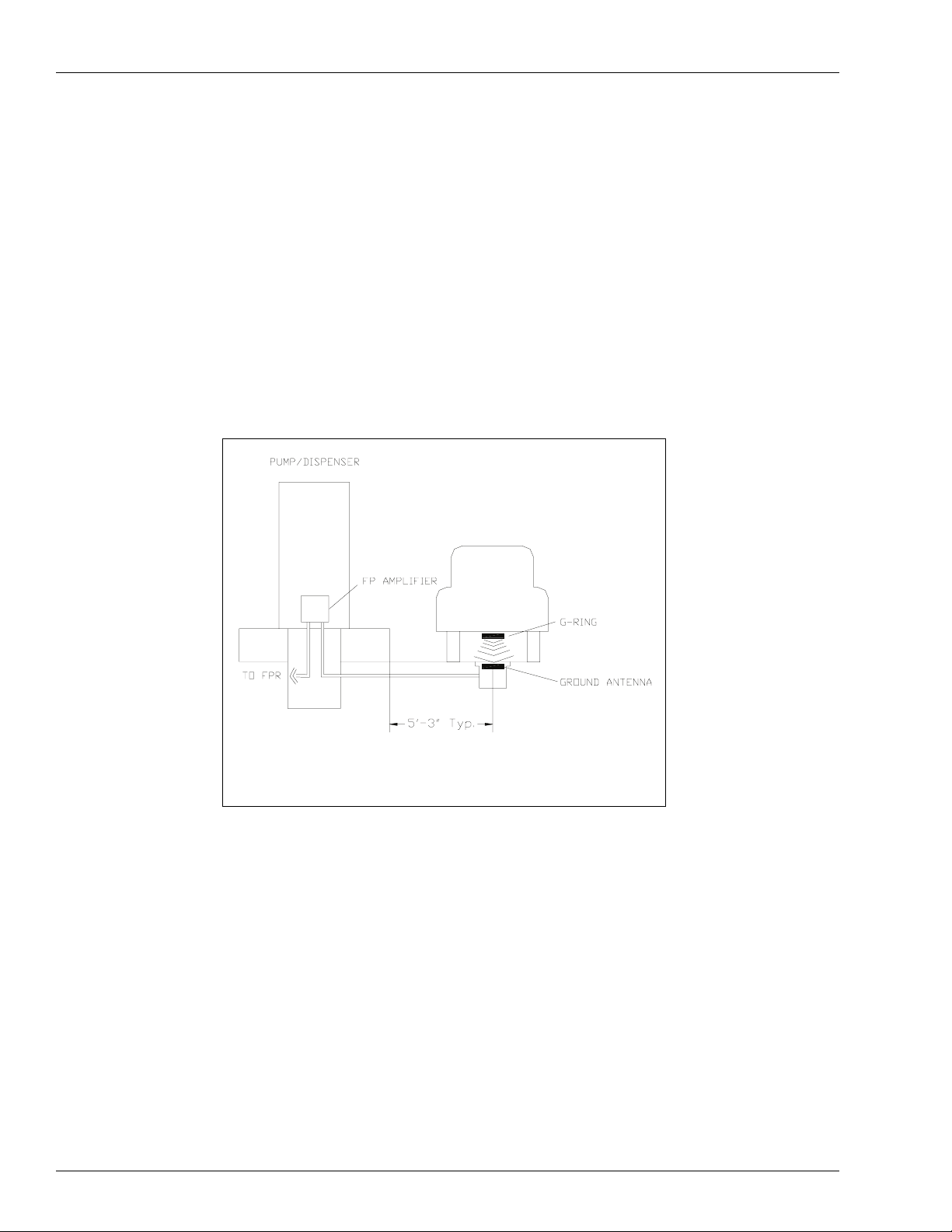
Installing A Fuel Point Ground Antenna For Fueling
Ground Antenna Installation Components are available in three (3) styles to meet most
common site requirements.
• Flush-Mount J-Box
• Direct Buried and Sealed
• Surface Mount
For fueling, the ground antenna should be located at half the width of a vehicle plus two feet,
or approximately 5 feet-3 inches out from the island and is normally aligned with the nozzle’s
on-hook position on the pump. The major factor affecting the final location is the relationship
of the vehicle G-Ring to the gas fill tube. Ideally, the vehicle G-Rings will be mounted near the
fill tube to take advantage of drivers’ experience in stopping to fuel. The mounting styles and
applications are explained below.
C09822 Junction Box
For Installing a Flush-mount J-Box Antenna
The antenna J-Box and conduit are designed for use at new sites or sites requiring extensive
pavement rework. Prior to pouring pavement, a flush-mounted composite plastic box is
installed in the pavement and ½ inch conduit routed to a Fuel Point amplifier installed in the
base of the pump. The antenna from antenna kit (C07362) lays freely on top. Leave slack in
the wiring to allow removal of the cover for service.
Figure 3-4 Installing a Flush-mount J-Box Antenna
MDE-4530 Fuel Point Ground Antenna Installation Instructions · November 2005 Page 13
Page 18

Installation C09716 Antenna Sealant
C09716 Antenna Sealant
For Installing a Direct Buried and Sealed Antenna
Locations where minimum pavement reconstruction is expected can bury the ground antenna
in a 7 inches x 7 inches x 2 inches deep recess chiseled in the pavement.
1 Saw a 3/16 inch x 1 inch deep slot that will be used to route the antenna lead into the Fuel
Point amplifier.
2 At the island, chisel in a second recess to allow drilling a ½ inch diameter hole starting below
the pavement and at an angle into the base of the pump.
WARNING
!
Ensure that you use appropriate sealing fittings to fill in any holes in the secondary fuel spill
containers.
Figure 3-5 Installing a Direct Buried and Sealed Antenna
3 After machining the pavement, flush the recesses and slots free of debris.
4 Add dry sand and tamp to fill the antenna recess, leaving a 1 inch deep recess.
5 Route lead-in cable supplied from the antenna recess to the FP Amplifier mounted in the base
of the pumps and wire to antenna with butt connectors supplied.
6 Mix ¼ gallon of sealant with hardener according to instructions on the container and seal the
antenna and lead-in slot. Sealant should be used only in the top ½ inch of the installation.
Page 14 MDE-4530 Fuel Point Ground Antenna Installation Instructions · November 2005
Page 19

C07364 Surface Mount Antenna Installation Installation
C07364 Surface Mount Antenna Installation
The Fuel Point antenna can be surface mounted at indoor or covered sites or where weather
conditions permit.
1 Locate the antenna housing with the nozzle and mark pavement and housing outline on the
side of the island.
2 Drill a ½ inch diameter hole (within the housing outline and not more than 1-1/2 inch above
pavement) into the base of the pump.
3 Attach the C07362 antenna in the recess on the bottom of housing. Attach cable using butt
connectors supplied and route and clamp cable in machined slot.
Figure 3-6 Installing a Surface Mount Antenna
4 Attach metal wire chamber bracket to the island end of the housing using the self threading
screws supplied.
5 Slide housing bracket against island. Drill all mounting holes. Install threaded inserts and
attach housing to ground.
MDE-4530 Fuel Point Ground Antenna Installation Instructions · November 2005 Page 15
Page 20

Installation Ground Antenna Used for Gate Control
Ground Antenna Used for Gate Control
IMPORTANT INFORMATION
Successful installation requires the special Fuel Point ground antenna
manufactured by Gasboy and careful attention to the instructions that
follow. Do not try to use the loop detector supplied with the gate
controller or the manufacturer’s entrance loop instructions.
Gate applications can use any of the installation methods described previously in the Installing
A Fuel Point Ground Antenna For Fueling section. When not using Surface Mount, the
installation should include pavement markings or other alternate methods to ensure that the
vehicles are routed over the ground antenna.
Locating and Installing the Fuel Point Ground Antenna
1 Mark the ground antenna position, normally centered in the lane leading to the gate. A
single ground antenna is good for lanes up to 12 feet wide.
Note: For Direct Buried and Sealed applications, ensure that the pavement is stable and at
least 3 to 4 inches thick. If the pavement is unstable, the ground antenna location should
be excavated and repaired before proceeding.
Note: For Surface Mount ground antenna on macadam, order optional Macadam Surface
Mount Kit C07365 in addition to the C07364 Surface Mount Kit.
Figure 3-7 Conduit and Junction Box Detail
2 Calculate the minimum distance between the gate and ground antenna by measuring the
distance between the front of the vehicle to the G-Ring mounting location and adding 10 feet
(clearance between gate and vehicle). If this dimension varies between vehicles, use the
greater distance for your calculation.
For optimum operation, the vehicle’s G-Ring should pass directly over the ground antenna.
For vehicles with properly installed rings (36 inches maximum height above ground and GRing spaced minimum of 1 inch from a solid metal surface), the G-Ring can be a maximum of
20 inches off center. For Flush Mount J-Box or ground antenna direct buried and sealed,
painting a center line will help align vehicles with the ground antenna. Using the Surface
Mount technique will provide this visual aid.
Ground antenna installation is the same as described previously in the Installing A Fuel Point
Ground Antenna For Fueling section, except that the lead-in cable will be routed to a roadside
junction box as shown in Figure 3-7.
Page 16 MDE-4530 Fuel Point Ground Antenna Installation Instructions · November 2005
Page 21

This page is intentionally left blank.
Page 22

© 2005 GASBOY
7300 West Friendly Avenue • Post Office Box 22087
Greensboro, North Carolina 27420
Phone 1-800-444-5529 • http://www.gasboy.com • Printed in the U.S.A.
 Loading...