

Page 1

DISPENSER AND HOSE RETROFIT
INSTALLATION MANUAL
C35593
GASBOY INTERNATIONAL LLC
Page 2

Page 3

FUEL POINT
DISPENSER AND HOSE RETROFIT
INSTALLATION
MANUAL
C35593
REV. 03/28/03
INSTALLERS - IMPORTANT
In addition to installation information, this manual contains warnings, safeguards
and procedures on the use and care o f the Fuel Point System. Please leave this
manual with the system owner after the installation is complete.
Copyright 2003 by Gasboy International LLC All rights reserved.
The information in this document is confidential and proprietary. No further disclosure shall be made without
permission from Gasboy International LLC. Gasboy International LLC believes that the information in this document
is accurate and reliable. However, we assume no responsibility for its use, nor for any infringements of patents or
other rights of third parties resulting from its use. We reserve the right to make changes at any time without notice.
GASBOY INTERNATIONAL LLC LANSDALE, PA
Page 4

IMPORTANT WARNINGS AND SAFEGUARDS
Gasoline and petroleum products are flammable. To avoid injury or death to persons or damage to equipment or
property, follow these listed warnings and other warnings and precautions outlined in this manual when installing, using,
or working around this equipment. Check with GASBOY Technical Services for compatibility of liquids with pump
materials.
TURN OFF AND LOCK OUT ALL POWER TO PUMP BEFORE PERFORMING SERVICE, MAINTENANCE OR IN THE EVENT
All products must be installed by a
qualified installer and used in
conformance with all building, fire, and
environmental codes and other safety
requirements applicable to its
installation and use, including, but not
limited to, NFPA 30, NFPA 30A, NFPA
395 & NFPA 70. A qualified installer is
familiar with fuel systems installations
under the above stated building, fire,
and environmental codes and other
safety requirements for the particular
type of installation.
This product is only part of a fuel
dispensing system and additional
equipment and accessories, such as,
but not limited to, breakaway
connectors, shear valves, pressure
regulators, flow limiters, and other
safety devices may be necessary to
meet the applicable codes.
For maximum safety, we recommend
that all employees be trained as to the
location and procedure for turning off
power to th e enti re system. Instru ctions
regarding proper operation of the
equipment along with the appropriate
safety warnings should be posted in
plain view at the fuel island.
Before performing service or
maintenance (including changing of fuel
filters or strainers) or in the event of a
fuel spill, turn off and lock out all power
to the system. In battery-powered
pumps, disconnect power source. In
submersible pump applications, turn off
and lock out power at the master panel
and close any impact valves to the
submersible pump and any other
dispensers which use that submersible
pump. AC power can feed back into a
shut-off dispenser when dispensers
share a common submersible pump or
starter relay. Also block islands so no
vehicles can pull up to the dispenser
when the dispenser is being worked on.
DO NOT use Teflon tape for any pipe
threads in the product.
DO NOT use consumer pumps for
pumping fuel or additives into aircraft.
DO NOT use commercial pumps for
direct fueling of aircraft without filters
and separators necessary to ensure
product purity.
DO NOT use where sanitary design is
required (for food products for human
consumption) or with water-based
liquids.
DO NOT smoke near the pump or when
using the pump.
DO NOT use near open flame or
electrical equipment which may ignite
fumes.
DO NOT permit the dispensing of
gasoline or other petroleum products
into a vehicle with its motor running.
DO NOT permit the dispensing of
gasoline or other petroleum products
into unapproved containers or into
approved containers in or on vehicles
includin g trucks. All contain ers must be
filled on the ground to prevent static
discharge. Always use Approved and
Listed hoses and nozzles with electric
pumps and dispensers.
DO NOT block open the nozzle in any
manner. Nozzles shall conform to UL
and NFPA code requirements for
attended or unattended service.
DO ensure that the pump is equipped
with proper filters based on the product
being dispensed and its intended use.
DO wear safety goggles and protective
clothes when dispensing any liquid
which may be potentially harmful or
hazardous.
DO keep all parts of body and loose
clothing clear of belts, pulleys, and other
exposed moving parts at all times.
OF A FUEL SPILL.
DO require washing and changing of
clothes if fuel is spilled on a person or
his/her clothing. Keep away from open
flames, sparks, or people smoking.
DO provide a receptacle for catching
product from pump/meter when
servicing.
DO clean up product spills on the
driveway. Turn off and lock out all
power prior to cleanup.
DO insure pump is properly grounded.
DO insure hose is compatible with fluid
being dispensed.
DO inspect hose, nozzle, and pump on
a regular basis for wear, damage, or
other conditions which may create a
safety or environmental hazard.
DO make sure all pipe threads are
properly cut and the inside reamed to
remove burrs. Use UL classified
gasoline-resisting compound on all
joints of gasoline handling piping.
Sealing compound must also be
resistant to Gasohol (Ethanol and
Methanol). Use gasoline-resistant pipe
compound on male threads only; pipe
compound used on female threads can
be squeezed into the supply line where
it can enter the product stream and
become lodged in the pump or meter.
DO ensure that junction box covers are
in place and properly tightened. Mating
surfaces between the box and cover
must be free of dirt, nicks, and
scratches. All unused entries into the
junction box must be properly plugged.
035282 Rev. 1267
GASBOY INTERNATIONAL LLC.
707 North Valley Forge Rd. Lansdale, PA, 19446 ● (215) 855-4631 ● FAX: (215) 855-0341
Page 5

CONTENTS
Section 1: INTRODUCTION
Purpose..................................................................................................... 1-1
System Overview ...................................................................................... 1-1
Fueling Sequence ..................................................................................... 1-2
Important Hose Modification Pointers - Read Before Proceeding............. 1-2
Testing the Fuel Point Installation............................................................. 1-3
Component Overview................................................................................ 1-4
Section 2: GETTING STARTED
General Information .................................................................................. 2-1
Before You Begin...................................................................................... 2-2
Approved Nozzles For Use With Dispenser Retrofit Kits .......................... 2-2
Dispenser Retrofit Jbox Assemblies.......................................................... 2-3
Unpacking the Dispenser Retrofit Kit ........................................................ 2-3
Fuel Point Hose Retrofit Kits..................................................................... 2-4
Internal Wire Retrofit Components............................................................ 2-7
Using This Manual..................................................................................... 2-8
Section 3: STANDARD INTERNAL WIRE HOSE RETROFIT
Step A: Disassemble Hose....................................................................... 3-1
Step B: Construct Hose Assemblies (Internal Wire)................................. 3-2
Step C: Final Hose and Nozzle Assembly................................................ 3-4
Step D: Reassemble ............................................................................... 3-5
Step E: Complete N-Ring Wiring.............................................................. 3-6
Step F: Apply Power and Check Installation............................................ 3-6
Section 4: VAPOR RECOVERY RETROFIT KITS
Vapor Recover Small Parts Kit, C07389................................................... 4-2
Step A: Construct Vapor Recovery Hose Assemblies............................... 4-3
Step B: Nozzle Assembly.......................................................................... 4-4
Step C: Final Vapor Recovery Hose Assembly......................................... 4-5
Step D: Reassemble Hose to Pump.......................................................... 4-6
Step E: Complete N-Ring Wiring............................................................... 4-7
Step F: Apply Power and Check Installation............................................. 4-7
03/28/03 Contents-1
Page 6

Page 7
Section 1
INTRODUCTION
PURPOSE
The GASBOY Fuel Point Dispenser and Hose Retrofit Installation Manual is provided to assist you
in installing the Listed dispenser retrofit kits for the Fuel Point system on your pumps. This manual
should be supplied to the installer prior to installation to ensure your components are installed
properly. Faulty installations are the major cause of system malfunctions. The system
components must be installed as described in this manual to ensure the reliability and proper
operation of the system. Please read this entire manual before starting installation.
GASBOY provides a toll-free number for customers and installer s having any questions pertaining
to the installation: 1-800-444-5529
SYSTEM OVERVIEW
Fuel Point adapts to Listed GASBOY fuel management systems for hassle-fr ee fueling. System
applications determine actual components required. Your system may consist of several or all of
the following components:
• a GASBOY fuel management system (FMS) (Listed models 1000, 1000P, or 2000S CFN)
• Fuel Point Reader (FPR)
• Pumps/dispensers modified using Listed Dispenser and Hose Retrofit Kits (consisting of I/S
Pre-amp and one or two kits)
• Vehicles equipped with materials from Vehicle Installation Kits (See Manual C35699)
• Vehicle Module(s) (VM’s)
03/28/03 1-1
Page 8

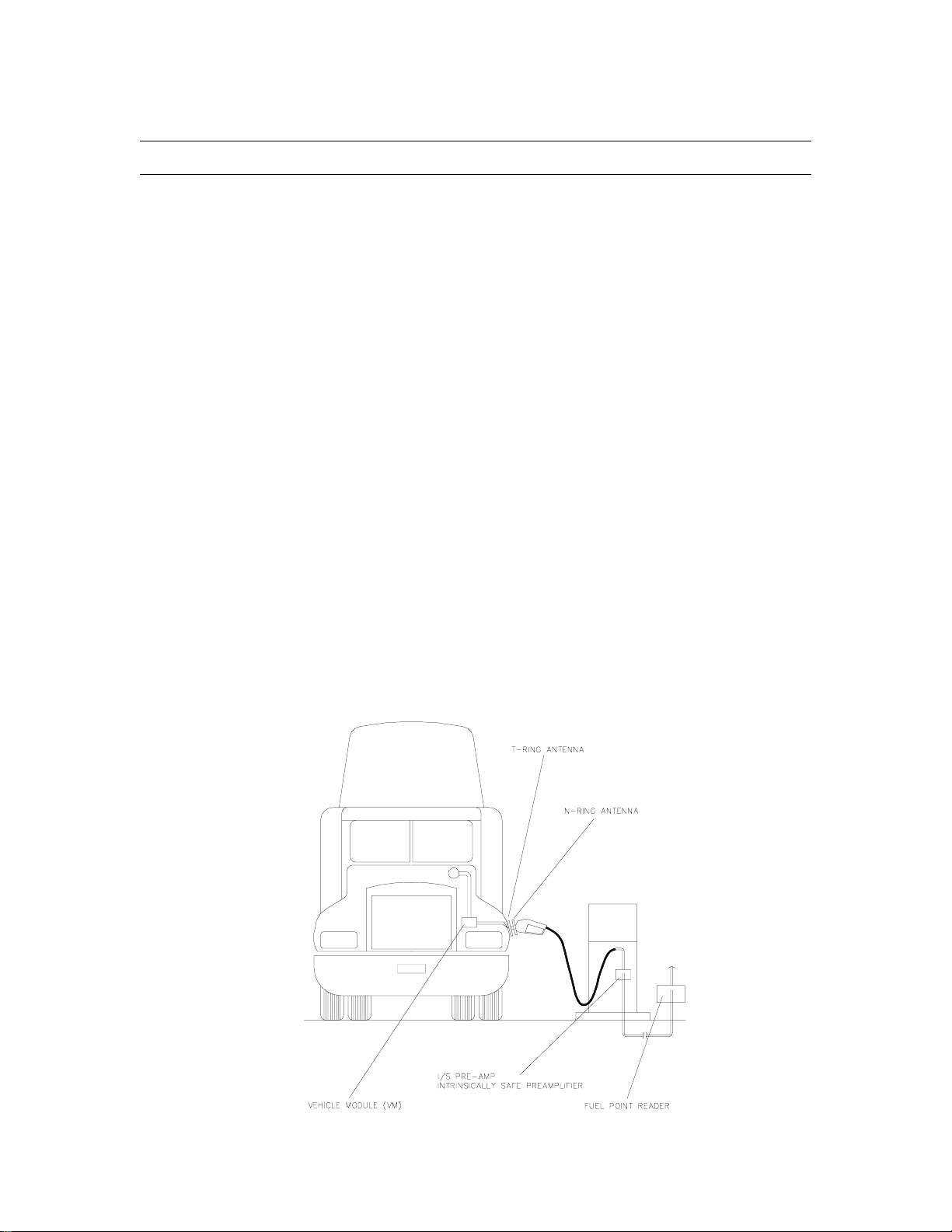
GASBOY Fuel Point System
FUELING SEQUENCE
Fueling a vehicle with a Fuel Point Vehicle Module (VM) is accomplished as follows:
1. Insert nozzle into vehicle tank. Vehicle ID, fuel control and odometer/hour data is
automatically transmitted from the VM via nozzle (N-Ring) and tank (T-Ring) antennas to the
Fuel Point Reader (FPR).
2. FPR communicates with the Fuel Management System (FMS) CFN or 1000 FleetKey unit.
3. FMS authorizes and records vehicle data.
4. When the nozzle is removed, it suspends the transaction, Reinsertion resumes transaction.
5. Transaction terminates when dispenser is turned off, nozzle is inserted into another vehicle, or
suspended transaction is not resumed.
6. Transactions are stored in memory for on-demand retrieval and logger printout.
IMPORTANT HOSE MODIFICATION POINTERS - READ BEFORE
PROCEEDING
Modifying the hose at a work bench is recommended. Use appropriate tools and components. For
reliable and long-lasting installations pay particular attention to the following points as you read the
remainder of the manual:
• Handle the internal hose wire assemblies carefully. Make sure the wire doesn’t become
nicked or cut. A damaged wire within the hose will allow fuel to enter and wick past O-ring
seals inside the jacket, leaking fuel at the connectors and inside the J-box/pre-amp assembly
in the base of the pump.
• If the system does not read the VM after installation of the antenna, first check for continuity
between the N-ring and pre-amp located in the J-box amplifier.
• PVC breakaway and nozzle covers are designed to conceal the breakaway connectors and
wire. The covers must be properly installed.
1-2 03/28/03
Page 9

Introduction
TESTING THE FUEL POINT INSTALLATION
The following test procedures are helpful:
• If the system is set up for use with cards or key activation, first test the pump using the card
or key. Pump a small amount of fuel and check the logger printout to insure the correct
amount is registered. This will test the complete system without the Fuel Point.
• If a master authorizer is available and programmed for the site, it can be used to test the
pump assembly. Hold the authorizer near the N-ring and activate.
• Test the modified pump with a vehicle equipped for use with Fuel Point.
• Verify the hose wiring. At the amplifier/j-box 35 to 40 ohms through the N-ring is required.
• The following chart provides details for using the Fuel Point Reader LED indicators (on
C08886 PCB) while troubleshooting wiring problems. The chart assumes only one vehicle is
fueling as DL3 and 4 are shared by up to 8 hoses. DL3 and 4 indicate the communications
between the FP Reader and FMS unit. DL1 and 2 indicate communications between the FP
Reader and Vehicle Module.
DL4 DL3 DL2 DL1
* * * *
Red Grn Red Grn
Pump/Nozzle Status Indicator Status Remarks
Not Pump/Nozzle dependent DL4,3 Flashing RS 485 communications.
Should be flashing
continuously. Should mirror the
2 Red LED’s on RS 485 PCB.
Nozzle inserted in vehicle DL1 flashes once Acknowledges Vehicle present.
Nozzle inserted in vehicle DL1,2 flash rapidly Vehicle Module sending data
to FP Reader.
Nozzle starts fueling DL1 flashes on-off Indicates nozzle is stilll present
in vehicle.
Nozzle removed DL1 ceases flashing after short
delay.
NOTE: Turning the pump handle to off or a system time out will cease all activity on DL3
and 4. When testing several vehicles, a small quantity of fuel should be pumped. If
quantity is not pumped, the system will shut off after a programmable number of no
quantity operations. The system must be re-enabled at the terminal. Refer to the
appropriate manual for system in use. When testing several transactions (nozzle
in/outs) you must delay about 5 seconds if communications is lost.
System in suspend mode.
Allows fueler to start fueling
second tank.
1065 1-3
Page 10
GASBOY Fuel Point System
COMPONENT OVERVIEW
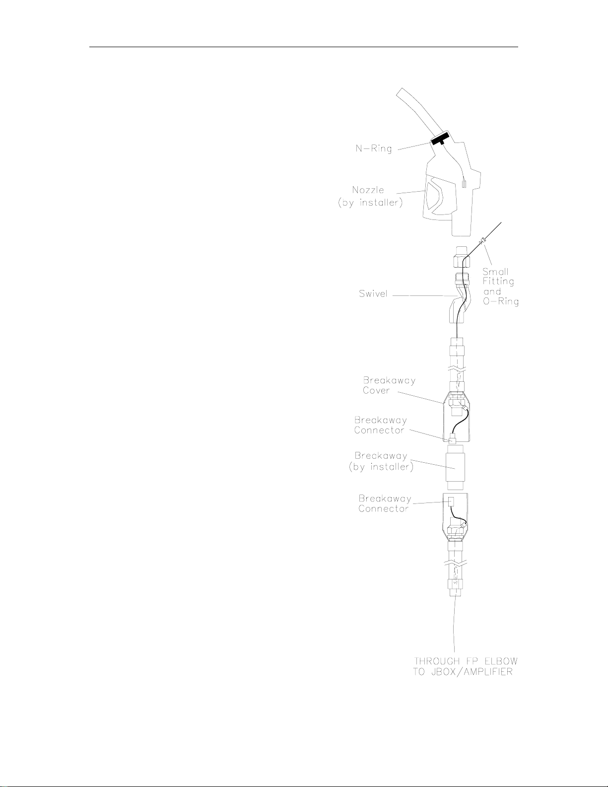
As you read the following descriptions, refer to the
drawing at the right for an overall view of the
assembled hose.
The GASBOY Fuel Point system requires
modification of existing pumps and hoses using
retrofit kits or installing internal-wired, factoryassembled hoses. Each hose outlet requires a
Fuel Point Amplifier available in single, twin or 2-4
hose multiple product assemblies. Hose retrofit
kits provide the parts for field modification of ULapproved fueling dispensers and pumps. To
discourage tampering, hose wiring is internal to the
hose or enclosed in flexible metal tubing.
Connectors are concealed by PVC covers and the
breakaway connector can be reconnected after
drive-offs
Hose assemblies and kits are available in a variety
of configurations for UL-Listed ¾” and 1” standard
and most Vapor Recovery style nozzles. Kits can
be assembled differently based on the breakaway
location. A list of kits and assembly instructions
are discussed later in this manual. Kits include
parts shown in the diagram at right except hoses,
nozzles and fuel breakaway which are to be
supplied by the installer. Wired hoses include
same parts plus the hoses.
The N-Ring assembly (nozzle antenna) mounts at
the base of the fueling spout of the nozzle. The NRing transmits and receives communications to
and from a Fuel Point-equipped vehicle via a TRing (tank ring antenna).
The hose wire provides communications between
the N-ring and Fuel Point J-Box/Amplifier mounted
in the base of the pump. Internal hose wiring
enters and exits the hose through special brass
fittings outfitted with O-ring compression seals.
Hose wires are constructed with a factory-installed
slack loop to compensate for hose stretch that can
occur during a drive-off.
1-4 03/28/03
Page 11

Section 2
GETTING STARTED
GENERAL INFORMATION
The following procedures assume the dispenser to be modified is UL-Listed and has been
installed according to the applicable codes, including a Listed hose assembly, hose nozzle valve,
and breakaway installed according to the manufacturer’s instructions. Apply a UL-classified pipe
lubricant/sealant to all pipe threads. Communications from the vehicle to the Fuel Point reader are
provided by the hose wire. GASBOY recommends that this wire be concealed from the end user
to discourage tampering.
Fuel Point dispensers may be configured in three styles depending on the individual application.
Give careful consideration to the hose style.
Style 1 (Breakaway at Dispenser) and Style 3 (Breakaway at Nozzle) can be constructed from
standard kits. Be sure to specify the kit that meets your particular hose length requirements. Style
3 (Breakaway at the High Hose Clamp) should be specified when a high hose feature is to be
used. Extended hose kits provide for up to a 20-foot main hose length. Style 1 or 2 should be
used where nozzle weight may be a consideration.
03/28/03 2-1
Page 12

GASBOY Fuel Point System
BEFORE YOU BEGIN
CAUTION: Assembly and installation of required components may require drilling and/or
sealing parts. Always assemble hose, nozzles, and any components away from
the fuel site in a safe environment where potentially hazardous fumes are not
present.
Use conduit layout drawings in the Fuel Point Reader Manual, C35628 and check installation for
Fuel Point conduits and J-boxes.
All installations must conform with all building/fire codes, all Federal, State, and Local codes,
National Electrical Code, (NFPA 70), NFPA 30, and Automotive and Marine Service Station Code
(NFPA 30A) codes and regulations. Canadian users must also comply with the Canadian
Electrical Code.
APPROVED NOZZLES FOR USE WITH DISPENSER RETROFIT KITS
Standard interchangeable UL-Listed 3/4 and 1" nozzles may be used with Fuel Point. Nozzle
selection may be affected by vehicle type, vehicle tank configurations, locations and opening
diameter. With the nozzle antenna ring (N-ring) installed, check each vehicle for the following:
• Install a test N-ring on the nozzle. For each vehicle, check the read distance from the N-ring
to vehicle tank (T-ring). Fuel Point will communicate when the rings are no more than 9"
apart provided there is no metal blocking the signal (because N-ring is inside fill collar
opening).
• Check that the nozzle spout is fully inserted into the vehicle’s tank opening and the vehicle
can be safely fueled. If necessary, use a nozzle with a longer spout (OPW 7H with #5 BHB0125 12" spout or Richards Mark 12). Note that longer nozzle may affect pump nozzle
hook/boot configuration.
Vapor Recovery nozzles approved for use with Fuel Point are listed in the table below.
Nozzle MFR. V/R Balanced V/R Balanced V/R Assisted
Short Spout Long Spout
OPW 211V & 211VXS 11VF & 111VXS 11VA & 11VAA
Emco/Wheaton 4015 A4001 & A4005 A4500 & A4505
Husky 5010 5210 V3
Healy ~ ~ 400 & 600
Catlow ~ ~ VM-1
NOTE: The above nozzles are only to be used if the dispenser “replacement label” indicates
acceptability.
For other special applications, call GASBOY Technical Service at 1-800-444-5529.
2-2 03/28/03
Page 13
Getting Started
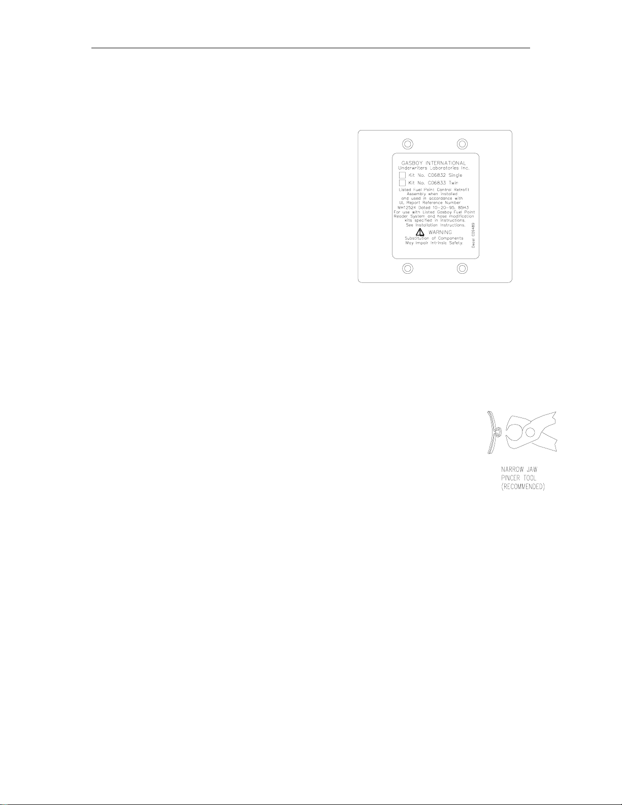
DISPENSER RETROFIT J-BOX ASSEMBLIES
For Fuel Point, each pump or dispenser will require at least one J-Box/Amplifier Assembly and
one Hose Retrofit Kit for each hose outlet from the list below.
J-Box/Amplifier Assembly
C06832 One Hose
C06833 Two Hose
UNPACKING THE DISPENSER RETROFIT KIT
The contents of the hose modification kit portion of the dispenser retrofit kit is broken down on the
following two pages. You will need the following tools to complete this installation:
• pipe wrenches
• screwdrivers
• meter
• small crescent wrench
• electrical tape
• electrician’s snake or pull wire
• scissors
• ruler
• UL-classified pipe thread sealant
• O-Ring lubricant (Parker O-Lube or
equivalent)
• 6" Heavy-duty tapered Head Cutters
Pliers (Klein, #490PL108)
• Automatic Single Squeeze wire stripper
(Stripmaster, #462ST028)
•
channel lock pliers
• special clamp pincer tool
for VR and VA nozzles
• Crimp tool with crimp
mechanism in head, not in
handle, (T&B #WT-111 or
Klein #490ST016)
03/28/03 2-3
Page 14

GASBOY Fuel Point System
FUEL POINT HOSE RETROFIT KITS
Retrofit Kits include Fuel Point specific parts required to modify existing pumping units. Dual
Plane swivel is included with kit. Hoses, nozzles and breakaways are supplied by the
installer.
¾” P/N 1” P/N V/R Description Max Hose Length
C07100 C07101 C07407 Standard Retrofit Hose Kit 13’ (1+12’)/(12+1’)
C07102 C07103 C07106 High Hose Retriever Retrofit Kit 13’ (6.5+ 6.5’)
C07183 C07104 C07408 Extended Hose Kit Retrofit Kit 21’ (1+20’)
C07440 C07105 ~ Extended High Hose Retrofit Kit 21’ (6+15’)*
C07400 C07401 C07109 Overhead Hose Retrofit Kit 10’ (9’+1)
Internal Wire Factory-Wired Hose Assembly Kit
Factory-wired hose assembly kits include Fuel Point components factor y-wir ed in hoses, complete
with swivel, fittings and hose wires fully assembled. Nozzles and breakaways are to supplied
by the installer
¾ P/N 1” P/N Description Hose Length
C07290 C07295 Wired Hose Assy Kit Standard B/A @ Pump 13’ (12+1)
C07291 C07296 Wired Hose Assy Kit Standard B/A @ Nozzle 13’ (1+12)
C07292 C07297 Wired Hose Assy Kit High Hose B/A Mid. 12’ (6 + 6)
C07293 C07298 Wired Hose Assy Kit Extended B/A @ Nozz 21’ (1 + 20)
C07441 C07402 Wired Hose Assy Kit Extd/High Hose B/A @ Mid. 20’ (6 + 15)*
C07294 C07299 Wired Hose Assy Kit Overhead B/A @ Pump 10’ (9 + 1)
*NOTE: Use this kit for applications where lower nozzle mounting height does not allow for
proper hose hangup, such as Gasboy 1” Front Load 9800A and 215A/216A Series
Pumps.
2-4 03/28/03
Page 15
Getting Started
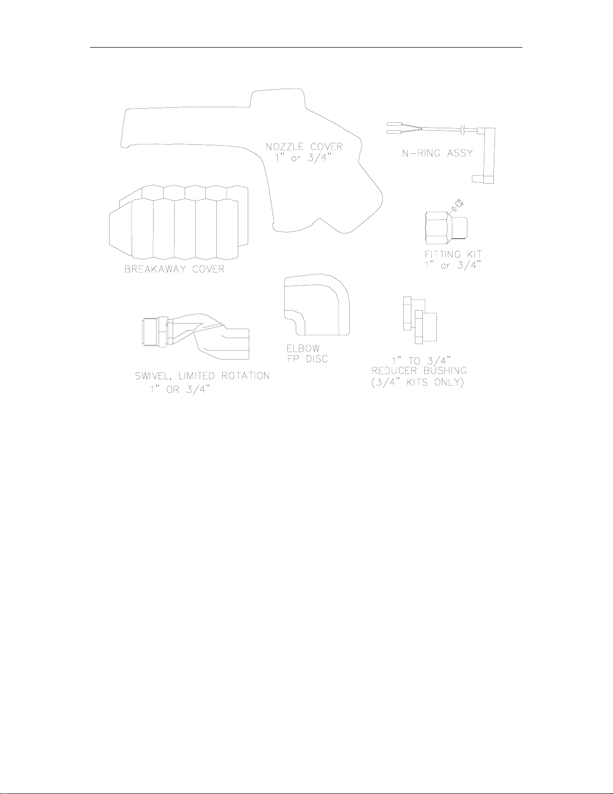
Kit Contents
1 012116 Nozzle Cover, 3/4”
012113 Nozzle Cover, 1”
2 C07279 N-Ring Assembly
3 012181 Breakaway Cover, Qty. 2
4 C07347 Fitting Kit, 3/4"
C07349 Fitting Kit, 1”
5 003622 Elbow, FP Disc
6 064574 Swivel, Limited Rotation, 3/4”
064575 Swivel, Limited Rotation, 1”
7 C09848 Reducer Bushing, Qty. 2 (3/4” kits only)
(See next page for Hose Wire Parts)
1065 2-5
Page 16
GASBOY Fuel Point System
Kit Contents (Continued)
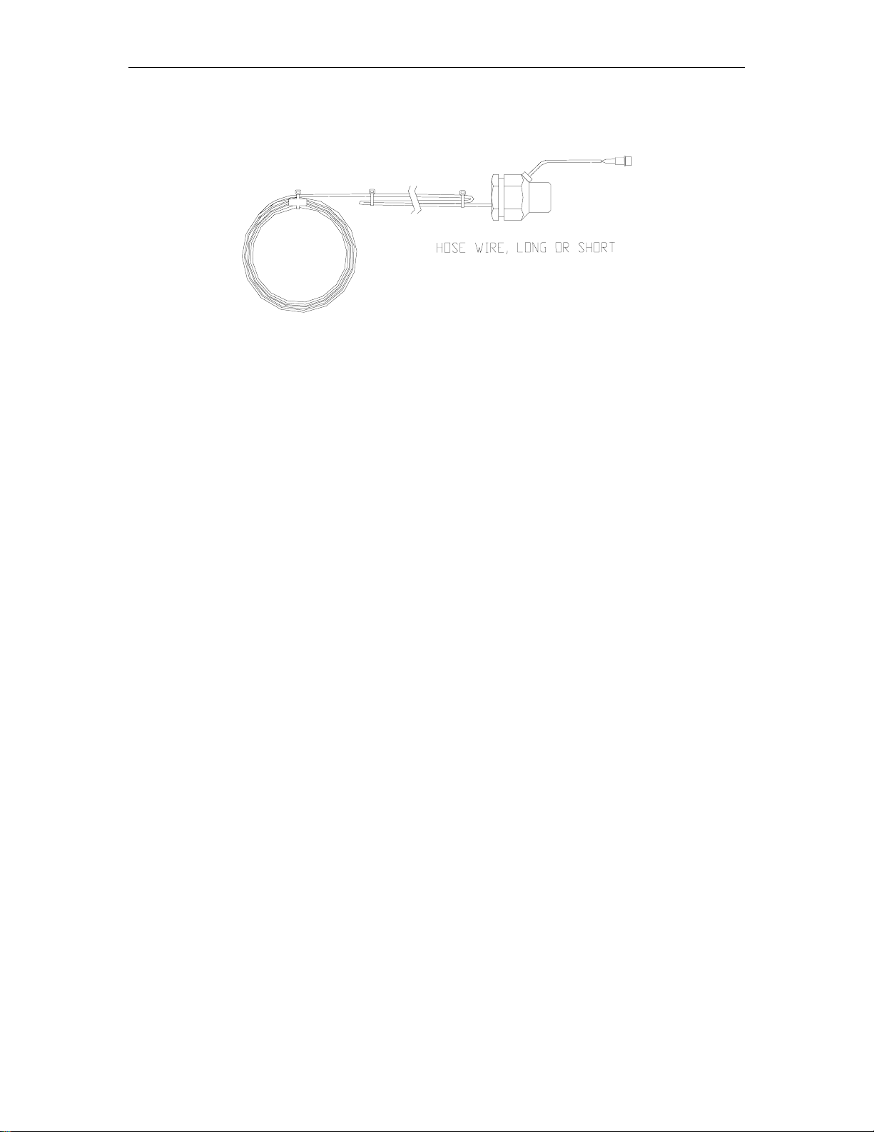
8 Short Hose Wire, Qty. 1
C07341 Wire Assy., 3/4" dia. x 1’ whip hose
C07342 Wire Assy., 3/4" dia. x 8’ hose max.
C07274 Wire Assy., 1" dia. x 1’ whip hose
C07275 Wire Assy., 1" dia. x 8’ hose max.
9 Long Hose Wire, Qty. 1
C07345 Wire Assy., 3/4" dia. x 6-8’ hose max.
C07346 Wire Assy., 3/4" dia. x 12-15’ hose max.
C07344 Wire Assy., 3/4" dia. x 20’ hose max.
C07325 Wire Assy., 1" dia. x 6-8’ hose max.
C07326 Wire Assy., 1" dia. x 12-15’ hose max.
C07327 Wire Assy., 1" dia. x 20’ hose max.
2-6 03/28/03
Page 17
Getting Started
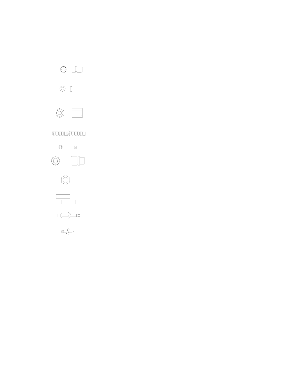
INTERNAL WIRE RETROFIT COMPONENTS
Internal Wire Small Parts Kit, C07348
1 C35972 Fitting, Hose Wire, Qty. 1
2 048865 O-Ring Seal, Qty. 2
3 C35999 Fitting, O-Ring, Tubing, Qty. 1
4 C36004 Tubing, Qty. 1
5 C09756 Plastic Bushing, Qty. 2
6 C09767 Fitting, ½” NPT Sealing, Qty. 1
7 039130 Nut, Conduit, ½” NPT, Qty. 1
8 C08899 Connector, Sealing Butt, Qty. 2
9 C08879 Tiewrap, Large, Qty. 2
10 0M0042 Tiewrap, Small, Qty. 2
1065 2-7
Page 18

GASBOY Fuel Point System
USING THIS MANUAL
The remainder of this manual contains procedures for assembling your antenna and hose. The
steps for hose retrofit are summarized below:
STANDARD HOSE RETROFIT
• STEP A: DISASSEMBLE HOSE
• STEP B: CONSTRUCT HOSE ASSEMBLIES (INTERNAL WIRE)
Hose #1 Assembly, Nozzle End
Hose #2 Assembly, Nearest Pump
• STEP C: FINAL HOSE AND NOZZLE ASSEMBLY
• STEP D: REASSEMBLE
Hose to Pump
• STEP E: COMPLETE N-RING WIRING
• STEP F: APPLY POWER AND CHECK INSTALLATION
VAPOR RECOVERY RETROFIT
• STEP A: CONSTRUCT VAPOR RECOVERY HOSE ASSEMBLIES
Hose 1 Assembly, Pump End
Hose 2 Assembly, Nozzle End
• STEP B: NOZZLE ASSEMBLY
• STEP C: FINAL VAPOR RECOVERY HOSE ASSEMBLY
• STEP D: REASSEMBLE HOSE TO PUMP
• STEP E: COMPLETE N-RING WIRING
• STEP F: APPLY POWER AND CHECK INSTALLATION
2-8 03/28/03
Page 19

Section 3
STANDARD INTERNAL WIRE HOSE RETROFIT
STEP A: DISASSEMBLE HOSE
1. Turn off pump power.
2. Remove hose assembly at the discharge elbow fitting. Be sure to provide a container under
the fitting to avoid any product spillage on the ground.
3. Drain and wipe hose to remove fuel residue and move to a safe location away from the
fueling site.
4. For Hose Retrofit Kits, follow Steps B through F.
5. For installation of a factory-wired hose, refer to assembled hose drawings in Step B and
proceed directly to Step C and follow Steps C through F.
03/28/03 3-1
Page 20

GASBOY Fuel Point System
STEP B: CONSTRUCT HOSE ASSEMBLIES (INTERNAL WIRE)
HOSE #1 ASSEMBLY (Nozzle End)
NOTE: All pipe threads must have UL-approved sealant applied and threads tightened fully.
Nozzle and breakaway are supplied by installer.
1. Refer to the pump diagram found earlier in this manual and determine the hose style required
(breakaway at nozzle, pump, or mid-hose at high hose clamp).
2. Starting at the breakaway end, carefully snake loose end of appropriate wire assembly
through the hose, taking care not to disturb the slack loop. Apply thread lubricant, thread
hose to large fitting and tighten fully.
3. Assemble the PVC breakaway cover as shown.
4. Use a pull wire and feed loose hose wire through swivel supplied with the kit. Apply thread
sealant and thread swivel to hose end.
5. Continuing at the swivel, locate the large fitting kit and remove small compression fitting and
O-ring and feed loose hose wire through large brass fitting and out the wire exit hose.
Reassemble the O-ring and compression fitting and tighten fully. Gently tug on the wire to
confirm it is fully sealed.
6. Set hose assembly aside and continue by assembling hose 2.
3-2 03/28/03
Page 21
Standard Hose Retrofit
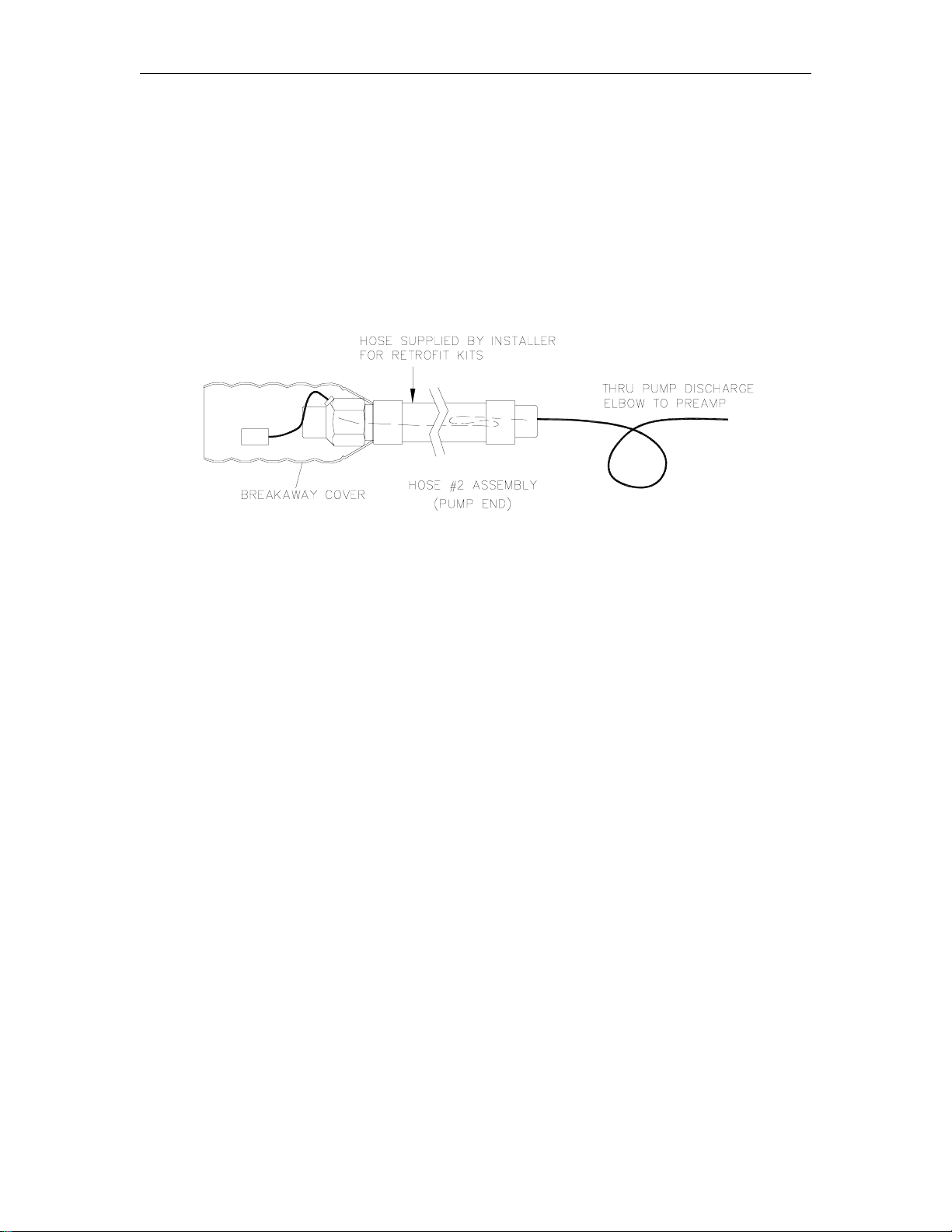
STEP B (CONT’D): CONSTRUCT HOSE ASSEMBLIES
Hose #2 Assembly (Nearest Pump)
7. Continuing at the breakaway, locate the second hose wire assembly from the kit and carefully
snake loose end through the hose (taking care not to disturb the slack loop), apply sealant and
thread large fitting on hose and fully tighten.
8. Assemble PVC cover as shown and proceed to STEP C: FINAL HOSE AND NOZZLE
ASSEMBLY.
9182 3-3
Page 22

GASBOY Fuel Point System
STEP C: FINAL HOSE AND NOZZLE ASSEMBLY
1. Assemble Breakaway and Nozzle: Determine
fuel flow direction and apply thread sealant to all
tapered threads. Assemble breakaway between
Hose #1 and Hose #2 according to
manufacturer’s directions. Install nozzle to Fuel
Point fitting on Hose #1. Tighten all connections
fully.
2. Complete N-Ring Wiring: Assemble N-ring on
nozzle. Strip 1-1/2” from hose wire outer jacket
and ¼” from 2 wires and crimp hose wire to N-ring
butt connectors Pull nozzle cover over the
nozzle, arrange wire to conceal and tiewrap as
needed. Stretch PVC cover to conceal brass wire
exit and tiewrap to close.
Assembly Note: To strip hose wire, first score
outer jacket using 12AWG stripper setting, then
strip using 10AWG setting.
3. Test N-Ring Wiring: Use ohmmeter and test N-
ring circuit for approximately a 35 ohm reading.
4. Test hose mechanically to insure nozzle shutoff
mechanism is operational and all fittings are fully
tightened.
5. Nozzles vary in design. If the handle locking
mechanism does not operate freely, remove the
lock bracket or replace with a nozzle with
mechanism designed within handle area.
3-4 03/28/03
Page 23
Standard Hose Retrofit
STEP D : REASSEMBLE
Hose to Pump
1. Install the J-Box/amplifier: Unless
installed previously, remove the cover
and install the portable cord fitting and
thread it to the J-Box. Thread the
assembly onto the I/S conduit which was
installed previously according to the Fuel
Point Reader Manual, C35628.
Assemble the wired hose to the pump.
2. Locate and install flex cable fitting:
Determine a location to install the flex
cable fitting (furnished with the hose kit).
Mark the location and remove the pump
trim panel to a safe location and machine
a 7/8” hole. Reinstall the trim panel and
install the flex cable fitting with conduit nut
supplied. Fully compress tubing in fitting
recess and secure with tiewrap.
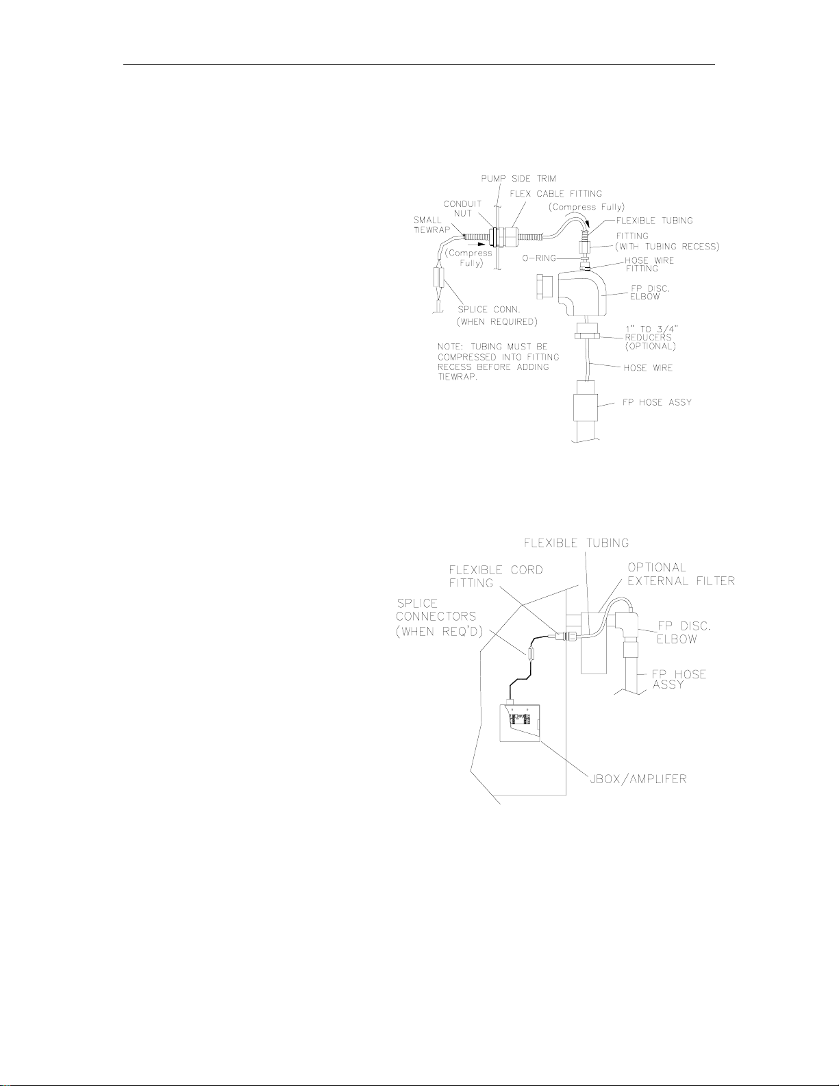
3. Complete hose wire installation:
NOTE: Use UL approved thread sealant on all tapered threads.
a. Remove the existing discharge
elbow and discard. Install Fuel
Point elbow from kit. For ¾” hose
installations install the two reducer
bushings supplied.
b. Assemble supplied hose wire
fitting and tighten fully with
wrench.
c. Use Hose 2 Assembly and feed
hose wire loose end through the
elbow and out the small exit fitting.
d. Cut hose wire lead to
approximately 24” from end of
hose, saving the trimmed wire for
later use.
e. Assemble O-ring (using O-ring
lubricant), tube fitting, tubing and
nylon bushing supplied. Tighten
fitting completely using wrench.
f. Fully compress tubing against fitting in recess and add tiewrap to hold in place.
g. Feed tubing and wire through the flex cable fitting, adjust and tighten.
h. Using trimmed wire, splice to hose wire using butt connectors supplied and route to J-
Box/amplifier.
i. Strip wire and connect to amplifier.
9182 3-5
Page 24
GASBOY Fuel Point System
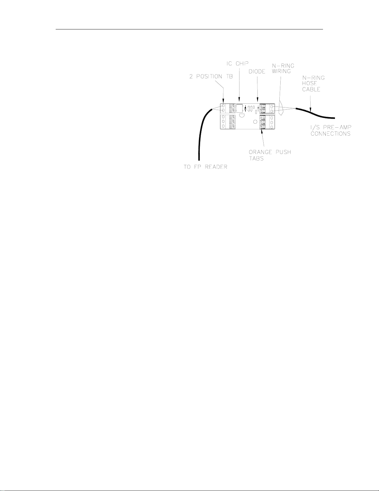
STEP E: COMPLETE N-RING WIRING
1. At the J-Box, cut the pump wire to
about a 15" length and remove 2" of
outer jacket. Strip (2) wires 3/8" from
the N-Ring hose cable. You are now
ready to make the final N-Ring
connections.
2. The N- Ring hose cable connects to the
two (2) section terminals nearest the
diode. To insert, press the orange tabs
and insert wire. Release tab and verify
a tight connection.
CAUTION: Wire polarity is not important, but connection to the wrong side of the pre-amp
assembly will cause damage!!!
STEP F: APPLY POWER AND CHECK INSTALLATION
IMPORTANT: Before applying power and checking installation, all wiring must be
complete from Fuel Point Reader to Junction Box Pre-amp. Refer to the
1. Return power to pumps and fuel management system. Switch system to AUTO operation.
For mechanical pumps, the switches are located on the pump control unit; for GASBOY
electronic pumps, these switches are on the CPU board behind the bezel assembly. For
other manufacturer’s pumps, refer to their installation/operation manuals.
2. Test the installation on a vehicle equiped to operate with Fuel Point. If communications ar e
intermittent, check and insure the N-ring and T-ring are within 9" of each other and the N-ring
communications path to the T-ring is not blocked by the metal fill tube (see TIP 1).
TIP 1: Vehicles with large metal fill pipes can allow the nozzle to be fully inserted in the tank
opening. The metal fill tube can block N-ring communications. If this condition exists, use a
nozzle with a extra long spout and provide a mechanism to hold the spout at a 5" to 9" gap
with the ring communication path unobstructed.
Once the system is communicating, pump a small amount of fuel and check for fuel leaks at
all threaded hose connections. For internally-wired hoses, check all O-ring seals and check
for faulty hose wires (see TIP 2).
TI P 2: If hose assembly leaks at one of the O-ring seals, tighten the pressure fitting only as
needed. Do not overtighten; this can also cause leaks. Finger tight, plus 1/4 to 3/8 turns is
sufficient torque to seal.
Internally wired hoses must be checked for damaged internal hose wiring (see WARNING).
WARNING: A nick or cut in the hose wire located within the hose will allow fuel to enter the
jacket interior and travel past o-ring seals. Fuel will be found in connectors and/or J-box.
When this occurs, immediately remove the pump from service and install new hose wiring.
appropriate installation/operation manuals to verify this.
3-6 03/28/03
Page 25

Section 4
VAPOR RECOVERY RETROFIT KITS
Fuel point Vapor Recovery Kits are available in several styles for most common applications
Two style kits are available depending on the type pumping unit used.
Standard single and twin pumps with a high hose retriever require High Hose retrofit kit. Due to
varying hose lengths used in these applications, the hose wire assemblies are available for 4-1/2’
hose, breakaway at the nozzle and 6-1/2’ hose, breakaway at the pump. The kit includes
additional parts for field-modification of other hose lengths.
Kits are available for GASBOY Astra pumps in standard lengths or extended for hoses up to and
including 20’ lengths. These kits require field modifications due to the unlimited hose lengths
encountered.
03/28/03 4-1
Page 26

GASBOY Fuel Point System
VAPOR RECOVERY SMALL PARTS KIT, C07389
4-2 03/28/03
Page 27
Vapor Recovery Retrofit Kits
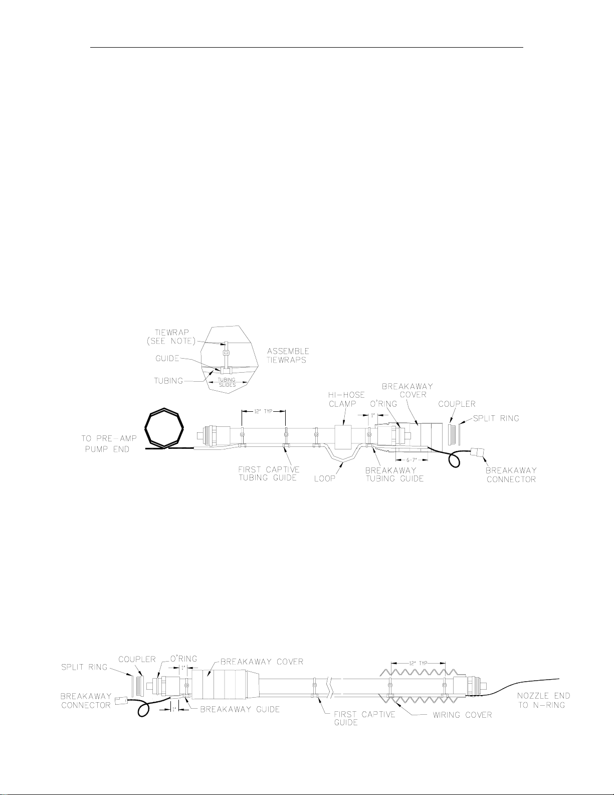
STEP A: CONSTRUCT VAPOR RECOVERY HOSE ASSEMBLIES
Hose 1 Assembly (Pump End)
1. Balanced hose assemblies require removal of one threaded coupler before proceeding.
Starting at the breakaway end, remove split ring and carefully remove coupler. Be careful not
to damage the O-ring seals. Set aside coupler and split ring for re-installation during Step C:
Final Vapor Recovery. (For high hose retractor applications, add the high hose clamp
approximately 6” from the hose end.)
2. Add PVC wire covers, trimming as needed with sharp scissors. Do not over-trim openings,
covers should fit tightly around hose.
3. Locate the appropriate wire assembly from the kit and assemble to the hose with 8” tiewraps
approximately at 12” centers (See diagram below). Slide tiewraps between the tubing and
the guide. Tiewraps must be assembled to allow the wire assembly to slide through the
plastic guides. (See diagram below). Do not tighten fully to allow adjustment during Final
Assembly. Inspect and lubricate O-ring and reassemble coupler to hose end. When a
clamp is used, adjust tubing to form a 2-3” loop.
Hose 2 Assembly (Nozzle End)
4. Assemble the nozzle end hose repeating Steps 1-3. Hose wire tubing is furnished to fit
popular hose lengths. The small parts kit contains parts to lengthen the tubing two
additional feet. For additional lengths less than two feet, the tubing can be cut to desired
length using a hacksaw and then deburred using a small file. To assemble the added
tubing, start at the nozzle end (end without connector) and cut the tiewrap. Assemble
bushings and tubing, compress slightly and hold in place using the small tiewrap supplied
with the kit.
03/28/03 4-3
Page 28
GASBOY Fuel Point System
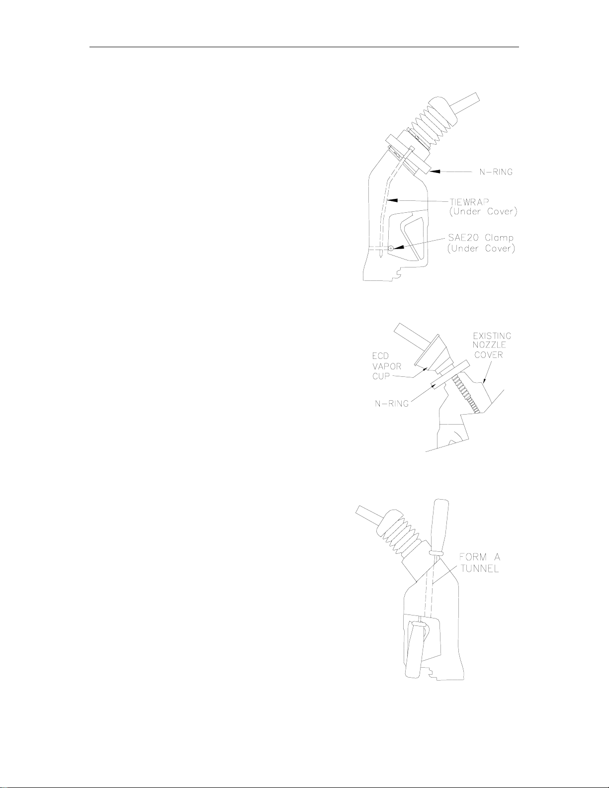
STEP B: NOZZLE ASSEMBLY
1. See Vapor Recovery Nozzle list (Section 2) for
nozzles approved by UL for use with Fuel Point.
Locate the N-Ring assembly and follow Step 2 for
balanced nozzle assemblies or follow Step 3 for Vapor
Assist nozzles.
2. For balanced nozzles with bellows, measure the
diameter of the bellows at the base of the spout just
above the check valve, if present. Trim the N-ring
membrane to a diameter slightly smaller than the
measured diameter. Pull the N-ring assembly over
the bellows end cap and position it at the bellows
base.
3. For assist-style nozzles using an ECD cup:
Increase the size of the opening in the N-ring
membrane enough to slip over the ECD cup.
Position the N-ring at the base of the nozzle spout.
4. Carefully feed the N-Ring cable under the nozzle
cover and along one side of the nozzle (See TIP
below). On the opposite side of the N-Ring, install
an 11” tiewrap and feed the tail under the cover and
down the opposite side of the nozzle.
TIP: Using two large screwdrivers, insert one from
the fuel spout end and the second from the
opposite end forming a tunnel to feed the
cable and the tiewrap under the nozzle cover.
Lift handles to enlarge the tunnel.
5. Assemble an SAE 20 mini- clamp around the nozzle
handle under the PVC cover to hold the cable and
tiewrap in place (see diagram above right). Adjust
the tubing and clamp so the does not interfere with
the nozzle handle operation. Set assembled nozzle
aside for final assembly later.
4-4 03/28/03
Page 29

Vapor Recovery Retrofit Kits
STEP C: FINAL VAPOR RECOVERY HOSE ASSEMBLY
1. Assemble Breakaway and Nozzle: Determine fuel
flow direction and assemble the fuel breakaway
between hose #1 and hose #2 according to
manufacturer’s directions. Tighten all connections
fully.
2. Complete N-Ring Wiring: Strip 1-1/2” from outer
jacket and ¼” from 2 wir es and crimp hose wire to
N-ring butt connectors. Clamp hose and N-ring
tubing using SAE 24 clamp provided. (see diagram
below). Test assembly to insure clamped tubing
restricts the swivel action at the nozzle coupling.
3. Test N-Ring Wiring: Mate the breakaway
connectors and test n-ring circuit for approximately a
35 ohm reading.
4. Test Mechanical Assembly: Insure nozzle shutoff
mechanism operates correctly and all threads are
tightened fully.
03/28/03 4-5
Page 30

GASBOY Fuel Point System
STEP D: REASSEMBLE HOSE TO PUMP
1. Install the J-Box/Amplifier: Unless installed
previously, remove the cover and thread the
portable cord fitting to J-Box. Thread J-Box to
I/S metal conduit installed previously according
to the Fuel Point Reader Manual C35628.
Assemble the wired hose to the pump.
2. Locate and Install Flex Cable Fitting:
Determine a location to install the flex cable
fitting furnished in the small parts kit. Mark the
location and remove the pump trim panel to a
safe location and machine a 7/8” diameter
hose. Reinstall the trim panel and install the
fitting with conduit nut supplied. For
installations using GASBOY-furnished hoses
with swivel lock mechanisms, proceed to Step
E: Complete N-Ring Wiring.
NOTE: Excess hose wire length can be
coiled and stored within the
pumping unit.
3. Install Swivel Limit Mechanisms:- Fuel Pointwired hoses cannot have continuous swivel motion
in the hose assembly. Swivel Limit Kits are
furnished and are to be installed following the
diagram at the right.
4. Clamp the aluminum stop bracket to the
breakaway using clamp furnished. WARNING: Do
not clamp to the hose coupling. Operation of
the swivel and stop bracket can loosen the
threaded coupling.
5. Install the stop clamp as shown and tighten fully.
6. Slide all PVC covers in place and proceed to Step
E: Complete N-Ring Wiring.
4-6 03/28/03
Page 31

Vapor Recovery Retrofit Kits
STEP E: COMPLETE N-RING WIRING
1. At the J-Box, cut the pump wire to
about a 15" length and remove 2" of
outer jacket. Strip (2) wires 3/8" from
the N-Ring hose cable. You are now
ready to make the final N-Ring
connections.
2. The N- Ring hose cable connects to the
two (2) section terminals nearest the
diode. To insert, press the orange tabs
and insert wire. Release tab and verify
a tight connection.
CAUTION: Wire polarity is not important, but connection to the wrong side of the pre-amp
assembly will cause damage!!!
STEP F: APPLY POWER AND CHECK INSTALLATION
IMPORTANT: Before applying power and checking installation, all wiring must be
complete from Fuel Point Reader to Junction Box Pre-amp. Refer to the
1. Return power to pumps and fuel management system. Switch system to AUTO operation.
For mechanical pumps, the switches are located on the pump control unit; for GASBOY
electronic pumps, these switches are on the CPU board behind the bezel assembly. For
other manufacturer’s pumps, refer to their installation/operation manuals.
2. Test the installation on a vehicle equipped to operate with Fuel Point. If communications are
intermittent, check and insure the N-ring and T-ring are within 9" of each other and the N-ring
communications path to the T-ring is not blocked by the metal fill tube (see TIP 1).
TIP 1: Vehicles with large metal fill pipes can allow the nozzle to be fully inserted in the tank
opening. The metal fill tube can block N-ring communications. If this condition exists, use a
nozzle with a extra long spout and provide a mechanism to hold the spout at a 5" to 9" gap
with the ring communication path unobstructed.
Once the system is communicating, pump a small amount of fuel and check for fuel leaks at
all threaded hose connections. For internally-wired hoses, check all O-ring seals and check
for faulty hose wires (see TIP 2).
TI P 2: If hose assembly leaks at one of the O-ring seals, tighten the pressure fitting only as
needed. Do not overtighten; this can also cause leaks. Finger tight, plus 1/4 to 3/8 turns is
sufficient torque to seal.
Internally wired hoses must be checked for damaged internal hose wiring (see WARNING).
WARNING: A nick or cut in the hose wire located within the hose will allow fuel to enter the
jacket interior and travel past o-ring seals. Fuel will be found in connectors and/or J-box.
When this occurs, immediately remove the pump from service and install new hose wiring.
appropriate installation/operation manuals to verify this.
03/28/03 4-7
Page 32
GW01 - 6/04/02 Rev. 1
WARRANTY
General Statements:
Gasboy International LLC. warrants all new equipment manufactured by Gasboy agai nst defective mat eri al and/or workmanship, for the warranty
period specified below, when the equipment i s installed in accordanc e with specifications prepared by Gas boy.
This warranty does not cover damage caused by acci dent, abuse, Acts of God, lack of surveillance of automatic recording systems, negligence,
mis-application, faulty installation, improper or unauthorized maintenanc e, installation or use in vi ol ation of product manuals , i n structions, or warnings.
Under no circumstanc e shall Gasboy be liable for any indirect , special, or consequent i al damages, losses, or expenses to include, but not limited
to, loss of product, los s of profits, litigation fees , or the use, or inability to use, our product for any for any purpose whatsoever.
Parts Only - During the warranty period, Gasboy will, at its option, repair or replace defective parts returned transportat i on prepai d to its factory.
On-Site Labor Included - Gasboy will also provide, within the Continental United States and during the warranty period, the services of an
Authorized Service Representati ve (A S R) for on-site repair or replacement of defective parts.
Replacement Parts - A ny system com ponent s that are not part of the original system order, includi ng Island Card Readers, Pump Cont rol Uni ts, etc.,
are considered replacement part s.
Equipment Term Coverage
Commercial Pumps and Dispensers
Full-Cabinet Consumer Pum ps
Small Transfer Pumps, Meters,
Pressure Regulators
Keytrol One year from date of instal l ation or 18 mos. from date of
Fuel Management Systems :
- CFN/ Profit Point
- Series 1000/Fleetkey
- TopKAT
- Fuel Point Readers
(sold with new systems)
Additional Fuel Point Items:
- Fuel Point Readers sold for
retrofitting existing systems.
- Fuel Point vehicle and dispenser
components.
Encoders, Embos sers, Modems,
CRTs, and Logger Printers
Air Diaphragm Pumps Three years from date of purchas e (for full warranty
Items not m anufactured by Gasboy
(ex. automatic nozzles, hoses, swivels,
etc.)
Replacement Parts One year from date of Gasboy International ' s invoice to the
To the extent permitted by law, this warranty is made in lieu of all other warranties , expressed or implied, includi ng warranties of freedom from patent
infringement, or merchant abilit y, or fitness for a particular purpose, or arising from a course of dealing or us age of trade. No one is authorized to
vary the terms of the warranty nor may anyone make any warranty of representation, or assume any liability other than that herein stated, i n
connection with the sale desc ri bed herei n. The acceptance of any order by Gasboy International is expressly made subject to the purchaser' s
agreement to these condit i ons.
One year from date of install ation or 18 mos. from date of
Gasboy International’s invoi ce to the purchaser, whichever
comes first.
One year from date of install ation or 18 mos. from date of
Gasboy International’s invoi ce to the purchaser, whichever
comes first.- Excepting the Model 2020 Hand Pump, which
has a 90-day warranty from date of GASBOY International’s
invoice.
Gasboy International’s invoi ce to the purchaser, whichever
comes first.
One year from date of start-up or 15 mos. from date of
Gasboy International’s invoi ce to the purchaser, whichever
comes first .- The basic warranty only applies to systems
which have been started up by a Gasboy Authorized Service
Representative (ASR).
One year from date of start-up or 15 mos. from date of
Gasboy International’s invoi ce to the purchaser,
whichever comes first.
Purchased with Fuel Management Syst em (Encoders,
Embossers only):
90 days from the date of s t art-up by a Gasboy ASR, or 180
days from date of Gasboy I nternational's invoice, whichever
occurs first.
Purchased with Fuel Management System
(Modems, CRTs, and Logger Printers only):
Matches system warranty.
Purchased Separately:
90 days from date of Gasboy International's
invoice to the purchaser.
description, see Price List).
Not warranted by Gasboy International (consul t original
manufacturer’s warranty).
purchaser.
Parts and Labor.
Parts Only.
Parts and Labor.
Parts and Labor.
Parts Only.
Purchased with System
(Encoders, Embos sers only):
Parts only.
Purchased with System (Modems,
CRTs, Logger Printers only):
Matches system warranty.
Purchased Separately:
Parts Only.
Parts Only.
Not Applicable.
Parts Only.
GASBOY INTERNATIONAL LLC
P.O. Box 309, Lansdale, PA 19446 ● (800) 444-5579 ● FAX: (800) 444-5569 ● www.gasboy.com
 Loading...