

Page 1

MDE-4820H
88PPOORRTTCCOOMMMMVVEERRTTEER
R
OPERATION AND INSTALLATION MANUAL
This document P/N 817423401 is based on Orpak’s 8 port CommVerter
operation and installation manual P/N 817423400
Page 2

SAFETY CONSIDERATIONS
Read all warning notes and instructions carefully. They are included to help you installing the Product safely
in the highly flammable environment of the fuel station. Disregarding these warning notes and instructions
could result in serious injury or property damage. It is the installer responsibility to install, operate and
maintain the equipment according to the instructions given in this manual, and to conform to all applicable
codes, regulations and safety measures. Failure to do so could void all warranties associated with this
equipment.
Remember that the fuel station environment is highly flammable and combustible. Therefore, make sure
that actual installation is performed by experienced personnel, licensed to perform work in fuel station and at
a flammable environment, according to the local regulations and relevant standards.
WARNING - EXPLOSION HAZARD
Use separate conduit for the intrinsically safe. Do not run any other wires or cables through this conduit,
because this could create an explosion hazard.
Use standard test equipment only in the non- hazardous area of the fuel station, and approved test equipment
for the hazardo us areas.
In the installation and maintenance of the Product, comply with all applicable requirements of the National
Fire Protection Association NFPA-30 “Flammable and Combustible Liquids Code”, NFPA-30A “Code for
Motor Fuel Dispensing Facilities and Repair Garages”, NFPA-70 “National Electric Code”, federal, state and
local codes and any other applicable safety codes and regulations.
Do not perform metal work in a hazardous area. Sparks generated by drilling, tapping and other metal work
operations could ignite fuel vapors and flammable liquids, resulting in death, serious personal injury,
property loss and damage to you and other persons.
CAUTION - SHOCK HAZARD
Dangerous AC voltages that could cause death or serious personal injury are used to power the Product.
Always disconnect power before starting any work. The Product has more than one power supply connection
points. Disconnect all power before servicing.
WARNING – PASSING VEHICLES
When working in any open area of fuel station, beware of passing vehicles that could hit you. Block off the
work area to protect yourself and other persons. Use safety cones or other signaling devices.
Page 3

WARNING
Components substitutions could impair intrinsic safety.
Attaching unauthorized components or equipment will void your warranties.
CAUTION
Do not attempt to make any repair on the printed circuit boards residing in the Product, as this will void all
warranties related to this equipment.
PROPRIETY NOTICE
This document contains propriety and confidential information. It is the property of ORPAK SYSTEMS
Ltd. It may not be disclosed or reproduced in whole or in part without written consent of ORPAK
SYSTEMS. The information in this document is current as of the date of its publication, but is subject to
change without notice.
DISCLAIMER
This document is provided for reference only. Although every effort has been made to ensure correctness,
ORPAK SYSTEMS does not guarantee that there are no errors or omissions in this document.
This document is the property of:
ORPAK SYSTEMS Ltd.
ISRAEL
Page 4

Page 5

TABLE OF CONTENTS
Paragraph Page
GENERAL DESCRIPTION
1
1.1. SCOPE................................................................................................................................ 10
1.2. MANUAL ORGANIZATION............................................................................................ 10
1.3. GENERAL DESCRIPTION............................................................................................... 11
1.4. MODULES......................................................................................................................... 14
1.4.1. Modules .............................................................................................................................. 14
1.5. SPECIFICATIONS............................................................................................................. 15
1.5.1. Communication Rates......................................................................................................... 15
1.5.2. Electrical............................................................................................................................. 15
1.5.3. Mechanical Pump Rates ..................................................................................................... 15
1.5.4. Mechanical.......................................................................................................................... 16
1.5.5. Environmental..................................................................................................................... 16
1.6. PROTECTION ................................................................................................................... 16
2 APPLICA TIONS
2.1. SCOPE................................................................................................................................ 17
2.2. COMMVERTER SYSTEM ARCHITECTURE ................................................................ 17
2.2.1. General................................................................................................................................ 17
2.2.2. System Architecture 1: Centralized at the Station Office................................................... 18
2.2.3. System Architecture 2: Moved to the Isle Side .................................................................. 19
2.2.4. System Architecture 1: Using an OrPT and/or µVIT on the Isles...................................... 20
2.3. TYPES OF FUEL PUMP AND THEIR COMMUNICATION METHOD........................ 21
2.4. CONNECTORS.................................................................................................................. 24
2.4.1. General................................................................................................................................ 24
2.4.2. Mating a Connector ............................................................................................................ 25
2.5. LAN to RS-485 APPLICATION........................................................................................ 26
2.5.1. RS-485 Connector Pinout................................................................................................... 28
2.5.2. RS-485 Module Jumpers .................................................................................................... 28
2.6. LAN to RS-232 APPLICATION........................................................................................ 32
2.6.1. RS-232 Connector Pinout................................................................................................... 33
2.7. LAN to CURRENT LOOP................................................................................................. 34
8 Port CommVerter Operation and Installation
Manual
i
Page 6

TABLE OF CONTENTS
Paragraph Page
2.7.1. LAN to Current Loop Application...................................................................................... 34
2.7.2. Current Loop Connector Pinout.......................................................................................... 35
2.7.3. Current Loop Module Jumpers........................................................................................... 35
2.7.4. Current Loop Electronic Devices (Pump or any Current Loop Devices)........................... 36
2.7.5. Wayne Pump Configuration Example................................................................................. 39
2.7.6. Gilbarco Legacy & Gasboy 8800 Current Loop Electronic Pumps Configuration............40
2.7.6.1. SiteOmat Configuration for Gilbarco Legacy & Gasboy 8800 Current Loop Electronic
Pumps…………. ............................................................................................................................ 43
2.8. LAN to TOKHEIM APPLICATION ..................................................................................48
2.8.1. Tokheim Connector Pinout ................................................................................................. 49
2.8.2. Tokheim Module Jumpers................................................................................................... 49
2.8.3. Tokheim Electronic Devices (Pump or any Tokheim Devices)..........................................49
2.8.4. Addressing Dual-Sided Tokheim Pumps ............................................................................ 51
2.9. 4xCONTACTOR APPLICATION...................................................................................... 52
2.9.1. 4x Contactor Connector Pinout........................................................................................... 52
2.9.2. 4xContactor Module Jumpers.............................................................................................53
2.9.3. Station Setup ....................................................................................................................... 54
2.9.4. Pump Server Setup.............................................................................................................. 55
2.9.5. 8 Port CommVerter Setup................................................................................................... 56
2.10. LAN to RS422 APPLICATION.......................................................................................... 57
2.10.1. RS422 Module Application................................................................................................. 57
2.10.2. RS-422 Connector Pinout...................................................................................................58
2.10.3. Sub-RS422 Module Application......................................................................................... 58
2.11. LAN TO NUOVO PIGNONE APPLICATION.................................................................. 60
2.11.1. Nuovo Pignone Connector Pinout ......................................................................................61
2.11.2. COPTRON Communication to Nuovo Pignone Card........................................................ 61
2.12. LAN TO RS232/485 APPLICATION................................................................................. 61
2.12.1. RS-232/485 Connector Pinout............................................................................................ 62
.13 MECHANICAL PUMP INTERFACE (MPI-C)
2.13.. MECHANICAL PUMP INTERFACE (MPI-C)
2.13.1. MPI-C Connector Pinout and Signals................................................................................. 63
2.13.2. Mechanical Pump - Pulser Connections.............................................................................64
2.13.2.1. Pulse Rate....................................................................................................................... 64
2.13.2.2. Interface Connections..................................................................................................... 64
2.13.3. Pulse Divider....................................................................................................................... 66
2.13.4. Description for LED's on the MPI-C board........................................................................ 69
.................................................................62 2
ii
8 Port CommVerter Operation and I
nstallation Manual
Page 7

TABLE OF CONTENTS
Paragraph Page
2.14. 5-PORT LAN SWITCH...................................................................................................... 70
2.15. CETIL ER3 MODULE....................................................................................................... 72
2.15.1. Sub module (Suspend Resume Relay Card)....................................................................... 73
2.15.2. Sub Module Pumalan.......................................................................................................... 74
2.16. DOOR OPEN DETECTION.............................................................................................. 75
2.16.1. Door Open Detector Installation......................................................................................... 75
3 COMMVERTER DESCRIPTION
3.1. SCOPE................................................................................................................................ 77
3.2. PHYSICAL......................................................................................................................... 77
3.2.1. Housing............................................................................................................................... 77
3.2.2. Front and Rear Panel .......................................................................................................... 78
3.3. LED INDICATORS............................................................................................................ 79
3.3.1. General................................................................................................................................ 79
3.3.2. Configuration...................................................................................................................... 79
3.4. MAIN BOARD CONNECTORS....................................................................................... 81
3.5. MAIN BOARD JUMPERS................................................................................................ 82
3.6. CHANGING THE IP ADDRESS....................................................................................... 83
4 INSTALLATION AND GROUNDING
4.1. GENERAL.......................................................................................................................... 89
4.2. PRELIMINARY PROCEDURES ...................................................................................... 89
4.2.1. Unpacking and Inspection .................................................................................................. 89
4.2.2. Installation Equipment........................................................................................................ 89
4.2.3. Protective Procedures ......................................................................................................... 90
4.3. INSTALLING THE COMMVERTER............................................................................... 90
4.3.1. General................................................................................................................................ 90
4.3.2. Desktop Installation............................................................................................................ 90
4.3.3. Cables’ Connections ........................................................................................................... 91
4.4. GROUNDING THE COMMVERTER .............................................................................. 92
4.4.1. General................................................................................................................................ 92
4.4.2. Grounding – General Concept............................................................................................ 92
4.4.3. Grounding the 8-port Commverter (without RS485 card) ................................................. 92
4.4.4. Grounding the 8-port Commverter (without RS485 card) ................................................. 93
4.4.5. Verifying the Grounding..................................................................................................... 94
8 Port CommVerter Operation and Installation
Manual
iii
Page 8

TABLE OF CONTENTS
Paragraph Page
4.5. SUB-MODULE INSTALLATION AND GROUNDING ..................................................94
4.5.1. Installation of Protective Isolator Sheet.............................................................................. 94
4.5.2. Connector Mechanical Outline – Check Procedure............................................................94
4.5.3. Sub-Module - Grounding.................................................................................................... 94
4.5.4. Sub-Module Installation – Wiring Label Placing ...............................................................94
4.6. SUB-MODULE REPLACEMENT - REMOVAL INSTRUCTIONS................................95
4.6.1. General................................................................................................................................ 95
4.6.2. Removal Tool – Spring ARC.............................................................................................. 96
4.6.3. Removal Tool – Procedures ................................................................................................97
5 SETUP AND CONFIGURATION
5.1. GENERAL.......................................................................................................................... 98
5.2. DISPLAYING THE MAIN PAGE ..................................................................................... 99
5.3. ETHERNET SETUP PROCEDURES................................................................................ 101
5.4. TCP PORTS SETUP PROCEDURES................................................................................ 102
5.5. SERIAL PORTS SETUP PROCEDURES ......................................................................... 103
5.6. PIPES SETUP PROCEDURES (NOT TO BE USED) ......................................................104
5.7. DIGITAL I/O PORTS SETUP PROCEDURES (NOT TO BE USED).............................. 105
5.7.1. Door Open Detection Digital I/O Port Setup...................................................................... 105
5.8. ADMINISTRATION TASKS PROCEDURES..................................................................107
5.8.1. EEPROM Save Procedures................................................................................................. 107
5.8.2. Service W eb Ports – TCP/IP Timeout Definition Procedures............................................. 109
5.8.3. Login Information Definition Procedures (Not to be used)................................................110
5.9. SYSTEM MONITOR INFORMATION SCREENS.......................................................... 111
5.9.1. General................................................................................................................................ 111
5.9.2. Counters Description .......................................................................................................... 113
5.10. TERMINAL SCREEN (Not to be used)............................................................................. 114
6 CHECKS AND TROUBLESHOOTING
6.1. GENERAL.......................................................................................................................... 115
6.2. POST-INSTALLATION CHECKS..................................................................................... 115
APPENDIX A UPGRADING THE COMMVERT ER TO A NEW VERSION
GENERAL......................................................................................................................................116
iv
8 Port CommVerter Operation and I
nstallation Manual
Page 9

TABLE OF CONTENTS
Paragraph Page
APPLICABILITY .......................................................................................................................... 116
UPGRADING PROCEDURES...................................................................................................... 116
PRELIMINARY SETUP PROCEDURES ..................................................................................... 116
SETTING THE APPLICATION PARAMETERS IN THE DHCP SER VER................................ 118
SETTING THE APPLICATION PARAMETERS ......................................................................... 119
FINAL PROCEDURES.................................................................................................................. 120
MPI-C - DYNAMIC PULSER SAMPLING PERIOD.................................................................. 121
1. GENERAL.......................................................................................................................... 121
2. CALCULATION ................................................................................................................ 121
3. SETTING THE MPI-C....................................................................................................... 122
APPENDIX B PLANNING AND CONNECTION OF PI’S
GENERAL ..................................................................................................................................... 123
CONNECTORS.............................................................................................................................. 123
WORKING WITH COMMVERTER ............................................................................................ 123
8 Port CommVerter Operation and Installation
Manual
v
Page 10

0
LIST OF ILLUSTRATIONS
Figure Page
FIGURE 1-1. COMMVERTER – GENERAL VIEW...................................................................11
FIGURE 1-2. COMMVERTER PCB - GENERAL VIEW........................................................... 12
FIGURE 2-1. COMMVERTER SYSTEM ARCHITECTURE – CENTRALIZED..................... 18
FIGURE 2-2. COMMVERTER SYSTEM ARCHITECTURE – MOVED TO ISLE SIDE ........19
FIGURE 2-3. COMMVERTER SYSTEM ARCHITECTURE – USING AN ORPT AND/OR µVIT2
FIGURE 2-4. COMMVERTER – CONNECTORS......................................................................24
FIGURE 2-5. COMMVERTER PCB - CONNECTORS.............................................................. 24
FIGURE 2-6. COMMVERTER – CONNECTOR........................................................................ 25
FIGURE 2-7. COMMVERTER – LAN TO RS-485 APPLICATION ..........................................26
FIGURE 2-8. RS-485 TWO PORT MODULE ............................................................................. 27
FIGURE 2-9. RS-485 MODULE JUMPERS................................................................................29
FIGURE 2-10 RS-485 ELECTRONIC PUMP - WIRING DIAGRAM ....................................... 30
FIGURE 2-11 RS-485 ELECTRONIC PUMP - WIRING DIAGRAM........................................31
FIGURE 2-12. LAN TO RS-232 CONFIGURATION..................................................................32
FIGURE 2-13. RS-232 TWO-PORT MODULE........................................................................... 32
FIGURE 2-14. CURRENT LOOP TWO-PORT MODULE......................................................... 34
FIGURE 2-15. CURRENT LOOP MODULE JUMPERS............................................................ 36
FIGURE 2-16. CURRENT LOOP WIRING DIAGRAM – SINGLE CLUSTER........................37
FIGURE 2-17. CURRENT LOOP WIRING DIAGRAM – MULTI CLUSTER.......................... 37
FIGURE 2-18. CURRENT LOOP ELECTRONIC PUMP-WIRING DIAGRAM....................... 38
FIGURE 2-19. COMMVERTER UNIT SETUP SITE – MAIN SCREEN..................................40
FIGURE 2-20. COMMVERTER UNIT SETUP SITE – ADMIN SCREEN................................41
FIGURE 2-21. COMMVERTER UNIT SETUP SITE – SERIAL PORTS SCREEN .................. 42
FIGURE 2-22. BUSES DIALOG BOX ........................................................................................ 43
FIGURE 2-23. SETUP PUMP SERVER DIALOG BOX............................................................. 44
FIGURE 2-24. PUMP SERVER SETTINGS DIALOG BOX...................................................... 45
FIGURE 2-25. SETUP PUMP SETTINGS DIALOG BOX .........................................................46
FIGURE 2-26. SETUP PUMP SETTINGS (MORE) DIALOG BOX.......................................... 47
FIGURE 2-27. LAN TO TOKHEIM CONFIGURATION ........................................................... 48
FIGURE 2-28. LAN TO TOKHEIM MODULE, TWO PUMPS CONFIGURATION................ 48
FIGURE 2-29 TOKHEIM ELECTRONIC PUMP - WIRING DIAGRAM .................................50
FIGURE 2-30 TOKHEIM ELECTRONIC PUMP - WIRING DIAGRAM .................................50
FIGURE 2-31 ADDRESSING TOKHEIM DUAL-SIDED PUMPS............................................51
FIGURE 2-31. 4XCONTACTOR MODULE................................................................................ 52
vi
8 Port CommVerter Operation and I
nstallation Manual
Page 11

LIST OF ILLUSTRATIONS
Figure Page
FIGURE 2-32. 4XCONTACTOR MODULE JUMPERS............................................................. 53
FIGURE 2-33. STATION SETUP.................................................................................................. 54
FIGURE 2-35. LAN TO RS422 CONFIGURATION................................................................... 57
FIGURE 2-36. RS422 MODULE ................................................................................................. 57
FIGURE 2-37. RS422 MODULE JUMPER J6 ............................................................................ 57
FIGURE 2-38. SUB-RS422 MODULE ........................................................................................ 59
FIGURE 2-39. NUOVO PIGNONE MODULE CONFIGURATION.......................................... 60
FIGURE 2-40. NUOVO PIGNONE MODULE ........................................................................... 60
FIGURE 2-41. MPI-C MODULE................................................................................................. 62
FIGURE 2-42. MPI-C WITH SUB-MODULE............................................................................. 62
FIGURE 2-43. MPI-C J2 AND J3 JUMPERS.............................................................................. 64
FIGURE 2-44 TERMINAL BLOCK WIRING CONNECTIONS ............................................... 65
FIGURE 2-45: LOW VOLTAGE ELECTRONIC PULSER ......................................................... 65
FIGURE 2-46 TERMINAL BLOCK AND 3-WIRE PULSER – WIRING CONNECTIONS .... 66
FIGURE 2-47. PULSE DIVIDER.................................................................................................. 66
FIGURE 2-48 LEDS ON THE MPI-C.......................................................................................... 69
FIGURE 2-49 5-PORT LAN SWITCH......................................................................................... 70
FIGURE 2-50 5-PORT LAN SWITCH ON 8-PORT PCB........................................................... 71
FIGURE 2-51. CETIL ER3 MODULE + SUB............................................................................ 72
FIGURE 2-52. COMVERTER EXTERNAL CONNECTOR...................................................... 72
FIGURE 2-53. CETIL SUB RELAY MODULE – CONNECTIONS........................................... 73
FIGURE 2-54. SUB MODULE PUMALAN – CONNECTIONS ............................................... 74
FIGURE 2-55. PUMALAN PORT MODULE – GENERAL VIEW CAT. NO. 819223445......... 74
FIGURE 2-56. DOOR OPEN DETECTOR CONNECTION........................................................ 76
FIGURE 3-1. COMMVERTER – FRONT PANEL...................................................................... 77
FIGURE 3-2. COMMVERTER – REAR PANEL (CURRENT LOOP / TOKHEIM
CONFIGURATION) ...................................................................................................................... 78
FIGURE 3-3. FRONT PANEL LEDS CONFIGURATION.......................................................... 79
FIGURE 3-4. COMMVERTER LEDS CONFIGURATION ON PCB........................................ 80
FIGURE 3-5. MAIN BOARD JUMPERS AND CONNECTORS............................................... 83
FIGURE 3-6. COMMVERTER UNIT SETUP SITE – MAIN SCREEN ................................... 84
FIGURE 3-7. COMMVERTER UNIT SETUP SITE – ADMIN SCREEN.................................. 85
FIGURE 3-8. COMMVERTER UNIT SETUP SITE – ETHERNET SCREEN .......................... 86
FIGURE 3-9. COMMVERTER UNIT SETUP SITE – TERMINAL SCREEN........................... 86
FIGURE 4-1. COMMVERTER UNIT – GROUNDING CABLE IN RS-485 CONNECTOR.... 92
FIGURE 4-2. COMMVERTER UNIT – GROUNDING THE UNIT (WITHOUT RS-485 CARD)93
8 Port CommVerter Operation and Installation
Manual
vii
Page 12

LIST OF ILLUSTRATIONS
Figure Page
FIGURE 4-3. COMMVERTER UNIT – DAMAGED SUB-MODULE.......................................95
FIGURE 4-4. SPRING ARC TOOL..............................................................................................96
FIGURE 4-5. SPRING ARC TOOL – DIMENSIONS ................................................................. 96
FIGURE 5-1. COMMVERTER UNIT – SETUP MAIN SCREEN.............................................. 99
FIGURE 5-2. SETUP MAIN SCREEN – FIELDS....................................................................... 100
FIGURE 5-3. ETHERNET SETUP SCREEN............................................................................... 101
FIGURE 5-4. TCP PORTS SETUP SCREEN...............................................................................102
FIGURE 5-5. SERIAL PORTS SETUP SCREEN........................................................................ 103
FIGURE 5-6. PIPES SETUP SCREEN......................................................................................... 104
FIGURE 5-7. DIGITAL I/O PORTS SETUP SCREEN................................................................105
FIGURE 5-8. DIGITAL I/O PORTS SETUP SCREEN – DOOR OPEN DETECTION
ACTIVATION................................................................................................................................. 106
FIGURE 5-9. ADMINISTRATION TASKS SCREEN................................................................. 107
FIGURE 5-10. SERVICE WEB PORTS – TCP/IP TIMEOUT SCREEN ....................................109
FIGURE 5-11. SERVICE WEB PORTS – TCP/IP TIMEOUT SCREEN ....................................110
FIGURE 5-12. SYSTEM MONITOR SCREEN – THREADS RUNNING.................................111
FIGURE 5-13. SYSTEM MONITOR SCREEN – SOCKETS, MEMORY, FILE STATUS........112
FIGURE 5-14. SYSTEM MONITOR SCREEN – RESET COUNTERS, CONFIGURATION
STATUS ..........................................................................................................................................112
FIGURE 5-15. TERMINAL SCREEN.......................................................................................... 114
FIGURE A-1. DHCP SERVER – COMMUNICATION PARAMETERS.................................... 118
FIGURE A-2 APPLICATION SETTING PARAMETERS............................................................ 119
FIGURE A-3 APPLICATION SETTING PARAMETERS............................................................ 120
viii
8 Port CommVerter Operation and I
nstallation Manual
Page 13

LIST OF TABLES
TABLE PAGE
TABLE 1-1. COMMVERTER MODULES................................................................................... 14
TABLE 2-1. RS-485 MODULE JUMPERS STATUS (ACCORDING TO PUMPS) ................... 28
TABLE 2-7. PULSE DIVIDER PINOUT...................................................................................... 68
TABLE 3-1. COMMVERTER LED INDICATION ...................................................................... 81
TABLE 3-2. MAIN BOARD CONNECTOR FUNCTIONALITY............................................... 81
TABLE 3-3. MAIN BOARD JUMPERS FUNCTIONALITY...................................................... 82
TABLE 4-1. COMMVERTER UNIT KIT.................................................................................... 89
8 Port CommVerter Operation and Installation Manual
ix
Page 14

0
SECTION
1
GENERAL DESCRIPTION
1.1. SCOPE
The 8 port CommVerter unit, referred to as "CommVerter" throughout this document, is a
component within the FuelOmat system. It serves as a universal and modular hardware interface
between the Ethernet communication from the Station Controller (FCC) and the other devices
communication interfaces such as RS485/422, Current Loop, etc.
As a communication interface unit, the CommVerter converts the Ethernet communication protocol
of any station devices into RS-485/422, Current Loop or Tokheim communication interfaces and
vice versa.
The CommVerter includes several modules designed to support each communication interface.
Some of these modules can be configured for different protocols by means of built-in Web pages.
The CommVerter unit is designed to survive the harsh forecourt environment. The RS-485 module
uses Spark Gaps protection for the links, and 1.5 KV isolation between the office controller and the
forecourt devices.
1.2. MANUAL ORGANIZATION
This manual provides information on the technical characteristics, installation and operation of the
CommVerter unit. This document deals with the physical level of the communication that is,
connecting the CommVerter unit to a network. It does not cover any software required to configure
the system. The manual is organized as follows:
Section 1. General Description: Includes general information regarding the CommVerter unit, its
components and functionality.
Section 2. Applications: Describes the types of communication where the CommVerter unit
provides interface applications.
Section 3. Description: Includes detailed information regarding the CommVerter unit and its
specifications.
Section 4. Installation and Removal: Provides instructions regarding the installation (and
removal) of the CommVerter unit at the station office.
Section 5. Setup and Configuration: Provides instructions concerning the instructions for the
setup and configuration of the CommVerter unit.
Section 6. Checks and Troubleshooting: Provides several recommended steps for checking the
system operability and for basic troubleshooting.
10
8 Port CommVerter operation and installation manual
Page 15

1.3. GENERAL DESCRIPTION
The CommVerter is a Communication Converter, interfacing serial Forecourt devices such as
pumps and tank level gauges to the station automation system through a standard TCP/IP Ethernet
port.
Unlike off-the-shelf Ethernet to Serial interfaces, the CommVerter is designed to function in the
harsh environment of the petrol stations; eliminating ground loops, power surges and other
RFI/EMI noise to maximize the performance and reliability of the station automation solution. Each
link is ‘floating’ and is DC isolated from all other links and has surge protection and enhanced
filtering.
There are two CommVerters configurations: one which is supplied as an enclosed unit which
includes an internal power supply (as shown in Figure 1-1) and the other as a PCB, which is
installed in Gilbarco's products (see Figure 1-2).
Figure 1-1. CommVerter – General View
8 Port CommVerter operation and installation
manual
11
Page 16

Figure 1-2. CommVerter PCB - General View
The unit supports a combination of up to 8 serial links of various standards as required at the
forecourt, including: RS-232, RS-485 and current loop.
All links are carried to the station automation controller over one Ethernet port.
The specific protocol for each of these forecourt devices is part of the station automation while the
CommVerter unit is the physical serial interface for the specific devices.
One of the prime tasks of the CommVerter at the forecourt is to interface to the dispensers. The
specific protocol for every dispenser type resides in the “pump server” software module of the
station automation and is standard for all Gilbarco’s home base controllers.
The CommVerter unit is part of Gilbarco’s complete station automation solution and is not an
off-the-shelf standard product, but has a modular structure to enable flexibility for various petrol
stations’ configurations and size.
The CommVerter is a platform with plug-in units to address each specific installation.
12
8 Port CommVerter operation and in
stallation manual
Page 17

Petrol stations around the globe are dramatically different in many aspects and the CommVerter
addresses all:
Total number of dispensers –several CommVerter units can be installed at the same
site.
Number of different dispensers at a specific site – various plug-ins are used,
according to the specific links that are required (RS-485, CL, Tokheim, etc.)
Number of contactless tag readers (OrTR, UPI, MiTag) and outdoor printers that
are needed at the petrol station (no more then 6 modules over one RS-485 link).
Number of tank level gauges and other 3rd party serial devices such as payment
terminals.
8 Port CommVerter operation and installation
manual
13
Page 18

1.4. MODULES
1.4.1. Modules
Several types of modules are available to support each communication type. The configuration of
the CommVerter for each application is determined by the type of the installed modules within.
Select the CommVerter module suitable to the conversion method required at your station network.
Table 1-1 lists the available CommVerter modules.
CommVerter Modules P/N
4xCONTACTOR 819223481
Current Loop 819223431
MPI-C+SUB 819223490
Nuevo Pignone (485) 819223485
RS232 819223451
RS232/485 819223441
RS422 819223471
RS422 + SUB 819223472
RS485 819223460
5V P.S. for 8-LAN switch 819523442
Table 1-1. CommVerter Modules
Cetil 819223425
Tokheim 819223420
Pumalan 819223445
14
8 Port CommVerter operation and in
stallation manual
Page 19

1.5. SPECIFICATIONS
Important Notice
At a rate above 9600 bps, the communication protocol with the 8Port Commverter shall handle 250 bytes
packets. The 8Port Commverter does not support a bytes stream flow at a rate higher than 9600 bps.
1.5.1. Communication Rates
The communication rates depend on the type of module.
No. Module Value
1 RS-232 Module 57600 bps max.
2 RS-485 Module 57600 bps max.
3 TCP/IP Module 100 Mbps (optional)
4 Current Loop 24V 45mA 9600 bps max.
5 Tokheim 9600 bps max.
1.5.2. Electrical
No. Parameter Value
1 Supply Voltage:
- Enclosed Commverter
unit
- PCB unit
110 – 230 VAC, 50-60Hz
15 to 24 VDC
2 Power Consumption Typical 5W
Maximum 25W
3 Protection 1.5A Fuse, internal on board.
1.5.3. Mechanical Pump Rates
No. Parameter Value
1 Power supply output voltage
12 VDC +/-20%
to Pulsar Unit
2 Power supply maximum
80 mA max
output current
3 Pulsar Input High level
10 to 16 VDC (standard)
voltage
8 Port CommVerter operation and installation manual
15
Page 20

4 to 10 VDC (require wiring changes)
4 Pulsar Input High level sink
3mA
current (@15V)
5 Maximum pulse rate of
Up to 5 KHz
MPI-C at 50% duty cycle
6 In use "On" level (Input) 4 to 7 VDC
7 In use "Off" level (Input) -1 to 1 VDC
8 In use Input impedance 10 KOhm
9 In use-max Input current
106 uA
using external dry contact
(5VDC)
10 In use-max Input current at 7
50 uA
VDC
11 12 VDC Output 25 mA max
1.5.4. Mechanical
No. Parameter Value
1 Dimensions (HxWxD) 140 x 180 x 50 (mm)
1.5.5. Environmental
No. Parameter Value
1 Operating Temperature
2 Operating Temperature (with power
-30C to +55C
-20C to +50C
supply)
3 Storage Temperature
-30C to +70C
1.6. PROTECTION
The CommVerter in its 485 communication port (refer to Table 1-1) is protected electrically against
lightening and surges using transorbers and gas discharge (Arrosto) devices.
Additionally, grounding is required. Proper grounding is essential for protection to take place.
Refer to paragraph 4.4 - Grounding the Commverter.
16
8 Port CommVerter operation and in
stallation manual
Page 21

0
SECTION
2
APPLICATIONS
2.1. SCOPE
This section provides the interfaces available between the CommVerter and several types of fuel
pumps. This section also includes several applications for the CommVerter in different se ttings
within the station. The CommVerter ensures proper communication between the FCC and the
station devices in accordance with their communication protocols.
2.2. COMMVERTER SYSTEM ARCHITECTURE
2.2.1. General
The CommVerter system architecture consideration depends on the topology of the specific petrol
station.
There are three main architectures:
Centralized at the station office
Moved to the isle side
When using an OrPT and/or µVIT on the isles
8 Port CommVerter Operation and Installation
Manual
17
Page 22

2.2.2. System Architecture 1: Centralized at the Station Office
The CommVerter is usually installed centralized at the station office together with the station
controller. This topology requires serial links all the way from the office to each dispenser or other
forecourt serial devices.
Figure 2-1. CommVerter System Architecture – Centralized
18
8 Port CommVerter Operation and I
nstallation Manual
Page 23
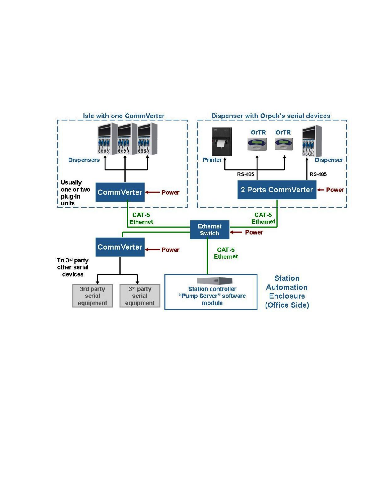
2.2.3. System Architecture 2: Moved to the Isle Side
In some applications, it is recommended to move the CommVerter to the isle side, carrying one
Ethernet link and power cable to the isle and then split to the serial links required at each isle.
Such an architecture usually requires only one or 2 plug-in units for each CommVerter on an isle.
Figure 2-2. CommVerter System Architecture – Moved to Isle Side
8 Port CommVerter Operation and Installation
Manual
19
Page 24
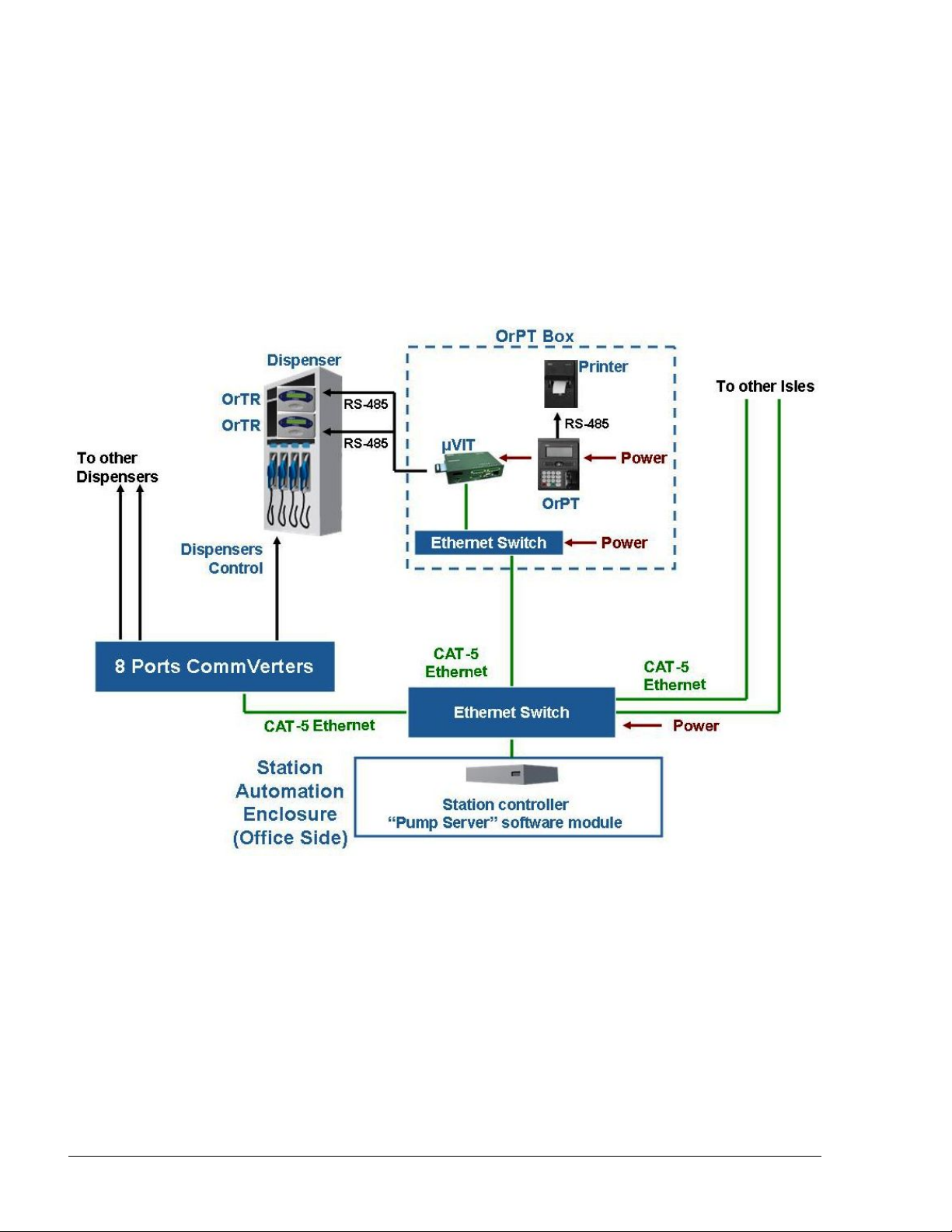
2.2.4. System Architecture 1: Using an OrPT and/or µVIT on the Isles
Other system configuration could be implemented when using an OrPT and/or µVIT on the isles.
In this configuration, both the OrPT and µVIT use a built-in Ethernet to RS-485 CommVerter,
supporting serial forecourt devices on the isle such as printers and contactless tag readers.
These links provided by the µVIT /OrPT could be off-loaded from the centralized CommVerter unit
to minimize cabling and installation cost.
Figure 2-3. CommVerter System Architecture – Using an OrPT and/or µVIT
20
8 Port CommVerter Operation and I
nstallation Manual
Page 25

2.3. TYPES OF FUEL PUMP AND THEIR COMMUNICATIO N METHOD
The CommVerter is used as an interface for several types of fuel pumps, as listed below:
Pump/Dispenser
Manufacturer
Model
(Protocol)
Aplab RS485 819223460 2 8 On 9600 8 None 1
Aplab
Swadesh II
Avery RS485 819223460 2 4 On 9600 8 Odd 1
Baransay
(Gilbarco)
Bennet
Mexico
Bennet
USA
Cetill
EAS1
Cetill
ER3
Dong HWA
(prime)
Communication
Type
RS485 819223460 5787 8 Even 1
RS232 819223451 2 1 N/A 4800 7 Odd 1
Current Loop 819223431 2 4 N/A 4800 8 Even 1
RS485 819223460 2 8 ? 2400 -
Cetil 819523425 1 1 ? 9600 8 None 1
RS485 819223460 2 remove
Board P/N No. of
channels
/ board
(include
sub
board)
Max
Number
of pump
heads
per
channel
Baud
Rate
Jumper
J1
Baud
Rate
Data
Bits
Parity Stop
7 Even 1
9600
9600 8 Even 1
Bits
ENE (=Prime
protocol)
EPCO (=Prime
protocol)
FuelStar RS485 819223460 2 8 Remove 4800 8 Even 1
Gilbarco
USA
Gasboy
USA
Gasboy
USA
Hong Yang RS232 2 4 N/A 4800 8 Even 1
Current Loop 819223431 2 8 Remove 5787 8 Even 1
RS422 819523471/2 2 8
RS485 819223460 2 8 Remove 9600 8 None 1
8 Port CommVerter Operation and Installation
Manual
21
Page 26

No. of
Pump/Dispenser
Manufacturer
Model
(Protocol)
IFSF
L&T
MPD/QPD
L&T
Sprint RS485 819223460 2 8 On 9600 8 None 1
L&T
Z-Line,
Pacemaker
L&T
Tulip ( Mono &
Dual) RS485 819223460 2 8 On 9600 8 None 1
L&T
VMP ( Mono &
Dual)
Communication
Type
USB - >LON or
PCI->LON
RS485 819223460 2 8 On 9600 8 None 1
RS485 819223460 2 8 On 9600 8 None 1
RS485 819223460 2 8 On 9600 8 None 1
Board P/N
1
channels
/ board
(include
sub
board)
Max
Number
of
pump
heads
per
channel
Max
Allowed
In LON
Baud
Rate
Jumper
Baud
Rate
Data
Bits
Parity
Stop
Bits
Maser RS485 819223460 2 8 9600 8 None 1
MPD/QPD RS485 819223460 2 8 Remove 19200 8 None 1
Midco
Single RS485 819223460 2 8 Remove 19200 8 None 1
Midco
MMS
Midco
Surefil RS485 819223460 2 8 Remove 19200 8 None 1
MPI-C
Rev D
MPI
Orpak RS485 819223460 2 8 On 9600 8 None 1
Mepsan RS-485 819223460 2 8 On 9600 8 Odd 1
LPG 2A
Dart/Mepsan RS-485 819223460 2 8 ? ? ? ?
Novotec RS485 819223460 2 8 9600 7 None 1
Nuovo Pignone
Blend
Nuovo Pignone N/P 819223485 2 1 2400 8 Odd 1
RS485 819223460 2 8 Remove 19200 8 None 1
81922349 0 2 1 On 9600 8 None 1
RS485 819223460 2 8 Remove 2400 8 Odd 1
22
8 Port CommVerter Operation and I
nstallation Manual
Page 27

No. of
Pump/Dispenser
Manufacturer
Model
(Protocol)
Petrotec
CEM
Prime RS485 819223460 2 8 Remove 9600 8 Even 1
Pumalan
HT-Retrofit Pumalan 819223445 2 8 N/A 4800 7 Odd 1
Pumptronics
Gilbarco
Real Tech China RS485 2 4 N/A 4800 8 Even 1
S&B T10 RS485 819223460 2 1 Remove 2400 7 Even 1
Schlumberger RS-422 819523471/2 2 1 N/A 1200 7 Even 1
Tatsuno
MPD/QPD RS485 819223460 2 8 Remove 19200 8 Even 1
Tatsuno
Pooly (Nonspace)
Communication
Type
RS422 819523471/2 2 1 N/A 1200 7 Even 2
Current Loop 819223431 2 4800
RS485 819223460 Remove 19200 8 Even 1
Board P/N
channels
/ board
(include
sub
board)
Max
Number
of
pump
heads
per
channel
Baud
Rate
Jumper
Baud
Rate
Data
Bits
Parity
Stop
Bits
Tatsuno Benc RS485 819223460 2 8 On 9600 7 EVEN 2
Tokheim Tokheim 819223420 2 1 N/A 9600 8 None 1
Tokheim Kaisen
L1+ RS485 819223460 2 1 On 9600 8 None 1
Tokheim 8800
(American
Dispenser)
Wayne
Dart RS485 819223460 2 8 On 9600 8 Odd 1
Wayne
Vista
Tokheim 819223420 2 1 N/A 9600 8 None 1
Current Loop 819223431 2 4 N/A 9600 8 Odd 1
8 Port CommVerter Operation and Installation
Manual
23
Page 28

2.4. CONNECTORS
2.4.1. General
The CommVerter in its basic version includes four separate connectors. Each connector supports up
to two distinctive channels for every module. However, in RS-422 and Sub RS-422 modules,
MPI-C and MPI-C + Sub, only one channel is supported.
A rear panel view of the CommVerter unit connectors is shown in Figure 2-4.
Figure 2-4. CommVerter – Connectors
A general view of the CommVerter connectors in PCB configuration (without the casing) is shown
in Figure 2-5.
Figure 2-5. CommVerter PCB - Connectors
24
8 Port CommVerter Operation and I
nstallation Manual
Page 29

2.4.2. Mating a Connector
The CommVerter kit includes one size mating connectors to be wired in accordance with the
selected fuel station configuration and consequently, the required conversion method.
To wire a mating connector (see Figure 2-6), proceed as follows:
1. For all modules, use standard 8-pin Phoenix-type male connector (P/N 813325001),
to be connected to the CommVerter.
2. For LAN connection, use RJ45 cat5 LAN cable (not included in the kit).
3. Wire the connector in accordance with its pinout definition as described in the
following paragraphs. The wiring shall be performed in accordance with the
CommVerter configuration.
NOTE
The connector pinout definition (pin number on top, signal
in second row) is provided when facing the connector,
from right to left.
4. The following paragraphs provide the wiring definition of the ports. These wiring
definitions are also shown on the connectors' labels (see Figure 2-4 and Figure 2-6).
Verify compatibility before connection!!!
Figure 2-6. CommVerter – Connector
8 Port CommVerter Operation and Installation
Manual
25
Page 30

2.5. LAN to RS-485 APPL ICATION
The LAN to RS-485 application is required when connecting fuel pumps and other serial devices to
home base controller that uses TCP/IP communication. In this configuration, the RS-485 Two-Port
module (P/N 819223460) is installed within the CommVerter.
If several CommVerter units are to be connected to the FCC, a Hub must be added to the network in
order to support several connections.
Figure 2-7. CommVerter – LAN to RS-485 Application
The CommVerter diverts the LAN communication to the relevant RS-485/422 device. The relevant
module is addressed with its IP address, and a unique port is configured during the device setup.
Interfaces using this mode of communication and conversion include Wayne Dart, Midco, L&T,
Tatsuno, Aplab, and more.
The following table provides the configuration of the RS-485 piggy-back board (Commverter
module) per type of pump.
Commverter Module Configuration
Aplab (485) 9600,8,N,1
Avery (485) 5700,8,E,1
Gilbarco (485) 9600,8,N,1
L & T (485) 9600,8,N,1
Midco (485) 19200,8,N,1
Nuovo Pignone (485) 2400,8,O,1
Tatsuno (485) 19200,8.E,1
Wayne Dart (485) 9600,8,O,1
26
8 Port CommVerter Operation and I
nstallation Manual
Page 31

Figure 2-8. RS-485 Two Port Module
LEDs Indication
NOTE
This module does not require opening the Commverter to
view the LEDs status and indications. The LEDs are
displayed through the holes of the Commverter cover.
The LEDs indication can be seen in the appropriate
column above the module installation position. The
column holes should be seen at the right-hand side from
the vents of the Power Supply, from top down.
Connector Side
Channel 1 Rx D4
Channel 2 Tx D6
Channel 1 Tx D1
Channel 2 Rx D11
Blank
Blank
LED Blinking – Communication on
LED Off – No communication
8 Port CommVerter Operation and Installation
Manual
27
Page 32

2.5.1. RS-485 Connector Pinout
The following pinout is required for the LAN to RS-485 application, for all devices that supports
RS-485 and RS-485 board.
[ Revision D and above ]
8 7 6 5 4 3 2 1
E G - + E G - +
Channel 2 Channel 1
2.5.2. RS-485 Module Jumpers
The jumpers in the RS-485 m
odule can be set in two different configurations, as shown in
Figure 3-7. The configuration is determined by four consecutive jumpers on the board: J1, J2, J5
and J6.
Every pair of jumpers is allocated to a different channel:
J1 and J2 for Channel 1 / J5 and J6 for Channel 2.
The jumpers determine the transmission rate. Two transmission rates can be selected:
9600 bps
4800 bps
To determine the transmission rate, set the jumpers accordingly. Proceed as follows:
1. Set the baud rate jumpers in the RS-485 cards in accordance with the pumps that
shall be connected to each channel (refer to Table 2-1).
The jumpers are: J1 for Channel 1 and J5 for Channel 2 (see Figure 2-9).
Table 2-1. RS-485 Module Jumpers Status (according to pumps)
8 port
Commverter
Baud rate
Jumper
Aplab Avery Gasboy MIDCO L&T NP NP Blend Tatsuno Wayne
Do not
remove
Do not
remove
Remove Remove
Do not
remove
Remove Remove Remove
Dart
Do not
remove
The Echo jumpers are J9 and J10.
If no jumpers exist echo is enabled.
If jumpers exist echo is disabled (factory default)
28
8 Port CommVerter Operation and I
nstallation Manual
Page 33

LED
Echo
jumper
Baud rate
jumper
* Jumper state 1 is the factory default setting
Figure 2-9. RS-485 Module Jumpers
8 Port CommVerter Operation and Installation
Manual
29
Page 34

RS-485 Electronic Device Pump (For any RS-485 Devices)
The wiring for the RS-485 electronic pump is provided as follows:
Figure 2-10 shows the specific wiring connections between the 8 Port RS-485 card
and the RS-485 pump nozzle, and the terminals that differ from the Mechanical
Pump. The figure shows the parallel connection between two RS-485 devices and
the Terminal Block.
Figure 2-10 RS-485 Electronic Pump - Wiring Diagram
30
8 Port CommVerter Operation and I
nstallation Manual
Page 35

Figure 2-11 RS-485 Electronic Pump - Wiring Diagram
8 Port CommVerter Operation and Installation
Manual
31
Page 36

2.6. LAN to RS-232 APPL ICATION
The LAN to RS-232 application is required when the connection to specific devices, such as TLGs,
is via RS-232. In this application, RS-232 Two-Port module (P/N 819223451) is installed within
the CommVerter.
Figure 2-12 shows a typical station configuration in which the CommVerter is used as an interface
between the Station Controller and several station devices - TLG.
Figure 2-12. LAN to RS-232 Configuration
Figure 2-13. RS-232 Two-Port Module
32
8 Port CommVerter Operation and I
nstallation Manual
Page 37

LEDs Indication
NOTE
This module does not require opening the Commverter to
view the LEDs status and indications. The LEDs are
displayed through the holes of the Commverter cover.
The LEDs indication can be seen in the appropriate
column above the module installation position. The
column holes should be seen at the right-hand side from
the vents of the Power Supply, from top down.
Connector Side
Channel 2 Rx D8
Channel 2 Tx D7
Channel 1 Rx D3
Channel 1 Tx D2
Blank
Blank
LED Blinking – Communication on
LED Off – No communication
2.6.1. RS-232 Connector Pinout
The following pinout is required for the LAN to RS-232 application.
8 7 6 5 4 3 2 1
G D I/O Rx Tx G D I/O Rx Tx
Channel 2 Channel 1
8 Port CommVerter Operation and Installation
Manual
33
Page 38

2.7. LAN to CURRENT LOOP
2.7.1. LAN to Current Loop Application
The LAN to Current Loop configuration is applicable whenever the CommVerter includes a
Current Loop Interface module (P/N 819223431). This communication conversion is used in
stations with pumps such as Wayne, Benett or Gilbarco that use current loop communication.
Figure 2-14. Current Loop Two-Port Module
34
8 Port CommVerter Operation and I
nstallation Manual
Page 39

LEDs Indication
NOTE
This module does not require opening the Commverter to
view the LEDs status and indications. The LEDs are
displayed through the holes of the Commverter cover.
The LEDs indication can be seen in the appropriate
column above the module installation position. The
column holes should be seen at the right-hand side from
the vents of the Power Supply, from top down.
Connector Side
Blank
Blank
Channel 1 Loop D1
Channel 2 Loop D7
Blank
Blank
LED On – Loop between the module and the pump
functional
LED Blinking – Communication on
LED Off – No communication
2.7.2. Current Loop Connector Pinout
The following pinout is required for the LAN to Current Loop application, for all Wayne and
Gilbarco pumps.
8 7 6 5 4 3 2 1
E G - + E G - +
Channel 2 Channel 1
2.7.3. Current Loop Module Jumpers
The jumpers in the Current Loop module can be set in two different configurations, as shown in
Figure 2-15. The configuration is determined by the two jumpers at opposite sides of the board.
Each configuration provides different power supply voltage:
12 Vdc
o
o 24 Vdc (default)
In addition, there are fur jumpers that determine the current level, as follows:
8 Port CommVerter Operation and Installation
Manual
35
Page 40

Jumpers J1, J4 installed; (for old PCBs J3, J6 also installed)
for 45 mA (default) consumption
Jumpers J1, J4 not installed; (for old PCBs J3, J6 also not
installed) for 20 mA consumption
Figure 2-15. Current Loop Module Jumpers
2.7.4. Current Loop Electronic Devices (Pump or any Current Loop Devices)
The wiring for the Current Loop electronic pump is provided as follows:
Figure 2-18 shows the specific wiring connections
and Current Loop pumps. Figure
2-16 and Figure 2-17 show the connection between two
between the 8 Port Current Loop card
Current Loop twin-pumps and the Terminal Block: In cases where connecting twin pumps
on a single cluster (module channel), set each pump with a different head number. If
connecting each twin pump on dedicated cluster, there is no need to reprogram the pump.
Pumps with identical Head number cannot be connected to the same Cluster.
36
8 Port CommVerter Operation and I
nstallation Manual
Page 41

Figure 2-16. Current Loop Wiring Diagram – Single Cluster
Figure 2-17. Current Loop Wiring Diagram – Multi Cluster
8 Port CommVerter Operation and Installation
Manual
37
Page 42

Figure 2-18. Current Loop Electronic Pump-Wiring Diagram
38
8 Port CommVerter Operation and I
nstallation Manual
Page 43

2.7.5. Wayne Pump Configuration Example
The following paragraph provides the pump configuration required for models
3/G7237D/GHJKM/ - P/N 887695-0154/053. Unit version: 54 IGEM
Verify programming codes on the pump as follows:
1. Set F01.00 to “1” for Serial Communications
2. Set F05.00 for the A side address (1-98)
3. Set F06.00 for the B side address (1-98)
4. Set F20.00 to “4” for US Current Loop
5. Set F20.01 to “02” for 9600 baud rate
6. Set F27.00 to “8” for Serial Comm
7. Set F27.01 to “0” for Serial Comm
8. Set F28.00 to “8” for Serial Comm
9. Set F28.01 to “0” for Serial Comm
NNOOTTEE
The F27 and F28 settings are dependant on whether
the unit was shipped with a Pulse Output board. If the
dispenser does not have pulse output, the above
settings should work. If it does have a pulse output
option and a pulse output template loaded, they may
need to be changed. For serial communication, they
should be set as noted above.
Make sure that the Current Jumper on Current Loop module (P/N MO9680B029) is set to 45 mA and
Voltage Jumper is set to 24 VDC.
Verify that the serial communication param
paragraphs 2.3 TYPES OF FUEL PUMP AND THEIR COMMUNICATION METHOD and 5.5
eters are set to: Baud 9600, Parity Odd, 1 stop bit (refer to
SERIAL PORTS SETUP PROCEDURES).
The Current
Loop connec
t
or on the Wayne Pump – US/UK J25 is found on the top right hand side.
8 Port CommVerter Operation and Installation
Manual
39
Page 44

2.7.6. Gilbarco Legacy & Gasboy 8800 Current Loop Electronic Pumps Configuration
To set up the Gasboy 8800 current loop electronic pumps install the current loop board in the
correct slot of the 8 port CommVerter board.
In the following example Slot 3 of the 8 port CommVerter board is used. The port assigned to
Channel 1 of this Slot is 3005.
NNOOTTEE
The Current Loop Interface module can be installed
in any slot of the 8 port CommVerter board. The slot
used may vary depending on system configuration.
Adjust the instructions according the Slot used for
the Current Loop Interface module board. The Slot
used is mapped to the assigned Port number.
In order for the Current loop board to communicate with the Gasboy 8800 pumps the ports setting
must be changed. Proceed as follows:
1. Connect the CommVerter to a PC (LAN Connection)
2. Open the Web browser, and enter the IP address of the Commverter. The Setup Main Screen
is displayed (see Figure 2-19)
Figure 2-19. CommVerter Unit Setup Site – Main Screen
40
8 Port CommVerter Operation and I
nstallation Manual
Page 45

3. Click on Admin Tasks. The Admin screen is displayed. Scroll down the page to reach the
TCP/IP timeouts section (see Figure 2-20)
Figure 2-20. CommVerter Unit Setup Site – Admin Screen
4. Select the Temporary disable (up to 5 minutes) checkbox
5. Click on the Send button in this section of the page
6. Select the Write to eeprom radio button in the Set/Get eeprom section
7. Click on the Send button in this section of the page
8. Select the Reset radio button in the Set/Get eeprom section
9. Click on the Send button in this section of the page
NNOOTTEE
These steps need to be completed in a timely manner
or the EEPROM will reset all changes made prior to
the reset.
8 Port CommVerter Operation and Installation
Manual
41
Page 46

10. Click on Serial Ports. The Serial Ports screen is displayed. Scroll down the page to reach
the Port that needs to be changed (see Figure 2-21)
11. This example refers to Port 205. Actual Port number2xx is determined by the Port assigned
to the Slot of the Current Loop Interface module board
12. Change the port setting as needed. See paragraph 2.3
13. Click on the Send button for the appropriate port
Figure 2-21. CommVerter Unit Setup Site – Serial Ports Screen
14. After changing and sending the Port settings, the eeprom must be updated and reset:
a. Click on Admin Tasks. The Admin screen is displayed
b. Select the Write to eeprom radio button in the Set/Get eeprom section
c. Click on the Send button in this section of the page
d. Select the Reset radio button in the Set/Get eeprom section
e. Click on the Send button in this section of the page
15. Give the system a few minutes to reboot and then verify that the settings have been saved.
42
8 Port CommVerter Operation and I
nstallation Manual
Page 47

2.7.6.1. SiteOmat Configuration for Gilbarco Legacy & Gasboy 8800 Current Loop Electronic Pumps
NNOOTTEE
For further information, please refer to SiteOmat
Installation and Maintenance Manual, P/N MDE-
4817.
In order to configure Gilbarco Legacy & Gasboy 8800 Current Loop Electronic Pumps, proceed as
follows:
1. Go to the SiteOmat Setup screen and click on the Advanced Mode button
2. Select the Buses tab. The Buses dialog box appears (see Figure 2-22)
Figure 2-22. Buses Dialog Box
8 Port CommVerter Operation and Installation
Manual
43
Page 48

3. Set up a bus for use by Gilbarco Legacy & Gasboy 8800 pumps. Note: port number may
differ.
4. Save the newly added Bus by clicking on the New button
5. Select the P. Servers tab. The Setup Pump Server dialog box appears (see Figure 2-23)
6. Set up a Pump Server for use by Gilbarco Legacy & Gasboy 8800 pumps. Note: port
number may differ
7. Save the newly added Pump Server by clicking on the New button
Figure 2-23. Setup Pump Server Dialog Box
8. After adding the Pump server, highlight the Pump Server and Click on the Addtl. Features
button. The Pump Server Settings dialog box appears (see Figure 2-24)
44
8 Port CommVerter Operation and I
nstallation Manual
Page 49

Figure 2-24. Pump Server Settings Dialog Box
9. Add a cluster for use by Gilbarco Legacy & Gasboy 8800 pumps. Be sure to select the
Enable Echo checkbox when adding the cluster
10. Save any changes that were made
11. On the Setup screen, click Save and then Reload. After the reload has been successfully
completed, the Gilbarco Legacy & Gasboy 8800 pumps may be added
12. Click on the Add Pump button on the Setup screen. The Setup Pump Settings dialog box
appears (see Figure 2-25)
8 Port CommVerter Operation and Installation
Manual
45
Page 50

Figure 2-25. Setup Pump Settings Dialog Box
13. Fill in the Pump number, Pump Head, and Number of hoses. The Pump Head number
must match the Pump ID set in Gilbarco Legacy & Gasboy 8800 pump
14. Select the correct Pump server and Cluster from the drop-down lists
15. Set the Message Factors as shown in the screen above. These settings work in most cases
but may need to be adjusted to make the pump and transaction data match
16. Set the Specific section as shown in the screen above. These settings work in most cases but
may need to be adjusted to match the specific pump used
17. Save any changes that were made
18. Select the newly added Pump
19. Select the More Options button. The following screen appears (see Figure 2-26)
20. Set the additional pa
rameters as shown in the screen below. These settings work in most
cases but may need to be adjusted to match the specific pump used
21. Save any changes that were made
22. On the Setup screen, click Save and then Reload
23. After the reload has completed successfully, verify that all added pumps have been saved.
46
8 Port CommVerter Operation and I
nstallation Manual
Page 51

Figure 2-26. Setup Pump Settings (More) Dialog Box
8 Port CommVerter Operation and Installation
Manual
47
Page 52

2.8. LAN to TOKHEIM APPLICATION
The LAN to Tokheim module is installed in the CommVerter whenever the pumps in the station are
of Tokheim brand. The CommVerter converts the LAN into Tokheim (and vice versa). Figure 2-27
shows a block diagram of a LAN to Tokheim communication application
Figure 2-27. LAN to Tokheim Configuration
o This module (two separate ports) interfaces with up to two pumps. In this configuration'
each pump is interfaced in a separate port.
o This module can be set to 5V or12V according to the Pump Interface requirement (Jumper
setting).
Figure 2-28. LAN to Tokheim Module, Two Pumps Configuration
48
8 Port CommVerter Operation and I
nstallation Manual
Page 53

LEDs Indication
NOTE
There is no external indication of the LEDs status.
Remove the Commverter cover to reveal the module
LEDs.
Connector Side
Channel 1 Rx D1
Channel 1 Tx D2
Channel 2 Rx D3
Channel 2 Tx D4
LED Blinking – Communication on
LED Off – No communication
2.8.1. Tokheim Connector Pinout
The following pinout is required for the LAN to Tokheim application, for all Tokheim brand
pump
s.
8 7 6 5 4 3 2 1
G COM TTC TTD G COM TTC TTD
Channel 2 Channel 1
2.8.2. Tokheim Module Jumpers
This module can be set to 5V or 12V according to the Pump Interface requirement. There are two
jumpers that determine the voltage level, as follows:
o Jumpers J1, J2 installed: 5V
o Jumpers J1, J2 removed: 12V
2.8.3. Tokheim Electronic Devices (Pump or any Tokheim Devices)
The wiring for the Tokheim electronic pump is provided as follows:
Figure 2-29 shows the specific wiring connections between the 8 Port Tokheim card
and the Tokheim pump nozzle, and the terminals that differ from the Mechanical
Pump.
8 Port CommVerter Operation and Installation
Manual
49
Page 54

8 PORT
MODULE
P/N:
819223420
DISPENSER
TTD
TTC
DCC-GND
Figure 2-29 Tokheim Electronic Pump - Wiring Diagram
Figure 2-30 Tokheim Electronic Pump - Wiring Diagram
50
8 Port CommVerter Operation and I
nstallation Manual
Page 55

2.8.4. Addressing Dual-Sided Tokheim Pumps
Figure 2-31 shows an example of the pump settings that should be defined in SiteOmat FCC to
address dual-sided Tokheim pumps.
Figure 2-31 Addressing Tokheim Dual-Sided Pumps
8 Port CommVerter Operation and Installation
Manual
51
Page 56

2.9. 4xCONTACTOR APPLICATION
The 4xContactor module includes four relays that toggle status from NC (normally close) to NO
(normally open), and vice versa in accordance with the jumper position (refer to paragraph 2.9.2).
This board is a relays module for four channels.
The relays contact rating is:
1A 24 VDC
0.5A 120 VAC
Figure 2-32. 4xCONTACTOR Module
2.9.1. 4x Contactor Connector Pinout
The following pinout is required for the 4x Contactor application.
8 7 6 5 4 3
2 1
K4 K3 K2 K1
Switch 4 Switch 3 Switch 2 Switch 1
52
8 Port CommVerter Operation and I
nstallation Manual
Page 57

2.9.2. 4xContactor Module Jumpers
The jumpers in the 4xContactor module can be set in two different configurations. The module
includes four consecutive jumpers, J1 to J4.
The jumper configuration determines the status of its related relay.
Figure 2-33. 4xCONTACTOR Module Jumpers
8 Port CommVerter Operation and Installation
Manual
53
Page 58

2.9.3. Station Setup
The relays control the pump's valve according to pump server's pump state which does not support
the suspend resume commands by protocol. Each valve of such pump should be connected to the
relay or through another power relay (according to the voltage or current needs of the valve). 2
pumps example connection is shown on Figure 2-34.
Figure 2-34. Station Setup
54
8 Port CommVerter Operation and I
nstallation Manual
Page 59

2.9.4. Pump Server Setup
The ini file contains definitions used to communicate with the relays.
Example for one pump is given below:
[cluster_01]
commtype=tcp
ip=192.168.1.108
port=3001
enable_echo=N
log_cluster_port=10001
[pump_01]
clusterid=1
addr=1
num_of_nozzles=1
specific=specific_01
[specific_01]
taiwan_soft_ver=N
use_relay=Y
relay_port=6500
relay_ip=192.168.1.108
relay_con_timeout=200
channel=1
New definitions are
relay_port – this is the Digital I/O port for relay's comm
relay_ip - The comverter IP where the relays are placed.
channel - The relay channel which will be activated ( it could be from 1 to 8 ) .
8 Port CommVerter Operation and Installation
Manual
55
Page 60

2.9.5. 8 Port CommVerter Setup
The 8 port CommVerter should be activated via its digital control (see Figure 2-35) listening port.
After setting the port number (should be the same as in the ini file of pump server) and enabling the
checkbox save and reset the CommVerter.
Figure 2-35. Digital Control
56
8 Port CommVerter Operation and Installation Manual
Page 61

2.10. LAN to RS422 APPLICATION
2.10.1. RS422 Module Application
The RS422 module (and the RS422 sub-module) transforms incoming data transmission into
RS-422 standard point to point. The RS422 module is installed on the main board and controls
Channel 1. In this module, pins 1 to 5 (GND) only are active, to provide RS422 transmission.
Figure 2-36. LAN to RS422 Configuration
Figure 2-37. RS422 Module
In order to disable echo, short Jumper J6 as shown in
Figure 2-38.
Figure 2-38. RS422 Module Jumper J6
8 Port CommVerter Operation and Installation
NNOOTTEE
Manual
57
Page 62

NOTE
There is no external indication of the LEDs status.
Remove the Commverter cover to reveal the module
LEDs.
LEDs Indication
Connector Side
Channel 1 Rx D4
Channel 1 Tx D1
LED Blinking – Communication on
LED Off – No communication
2.10.2. RS-422 Connector Pinout
The following pinout is required for the LAN to RS-422 application.
8 7 6 5 4 3 2 1
G T- T+ R- R+
2.10.3. Sub-RS422 Module Application
The RS422 Module has an additional sub-RS422 module on top of it (connector CN4). This
sub-module provide data transmission conversion into RS422 for Channel 2.
The pinout of the connection is the same as for the RS422 module. Pins 1 to 5 (GND) only are
active, to provide RS422 transmission).
58
8 Port CommVerter Operation and I
nstallation Manual
Page 63

Figure 2-39. Sub-RS422 Module
LEDs Indication
NOTE
There is no external indication of the LEDs status.
Remove the Commverter cover to reveal the module
LEDs.
Connector Side
Channel 2 Rx D4
Channel 2 Tx D1
LED Blinking – Communication on
LED Off – No communication
8 Port CommVerter Operation and Installation
Manual
59
Page 64

2.11. LAN TO NUOVO PIGNONE APPLICATION
The LAN to Nuovo Pignone module transforms data transmission into Nuovo Pignone Pump
Interface.
Figure 2-40. Nuovo Pignone Module Configuration
LEDs Indication
Figure 2-41. Nuovo Pignone Module
NOTE
There is no external indication of the LEDs status.
Remove the Commverter cover to reveal the module
LEDs.
Connector Side
Channel 1 Rx D15
Channel 1 Tx D16
Channel 2 Rx D17
Channel 2 Tx D18
LED Blinking – Communication on
LED Off – No communication
60
8 Port CommVerter Operation and I
nstallation Manual
Page 65

2.11.1. Nuovo Pignone Connector Pinout
The following pinout is required for the LAN to RS-232 application.
8 7 6 5 4 3 2 1
TX2- TX2+ RX2- RX2+ TX1- TX1+ RX1- RX1+
Channel 2 Channel 1
2.11.2. COPTRON Communication to Nuovo Pignone Card
Connector TB4A in Coptron pump (Pump Head 1)
Table 2-2 . Pump Communication Connector for 8 Port NP Module
Coptron
Pin Out
pin1_TXB pin3_Tx1+
Nuovo Pignone Card Pin Out
pin2_ TXA pin4_Tx1pin3_ RXB pin1_Rx1+
pin4_ RXA pin2_Rx1-
When Coptron dispenser detects serial-communication, it starts working in automatic mode.
2.12. LAN TO RS232/485 APPLICATION
This module is dual-purpose and supports two different communication protocols: RS232 and
RS485.
The LAN to RS-232 application is required when the connection to specific devices, such as TLGs,
is via RS-232. The RS232 circuit is dedicated for Channel 1
The LAN to RS-485 application is required when connecting fuel pumps and other serial devices to
home base controller that uses TCP/IP communication. The RS485 circuit is dedicated for
Channel 2.
NOTE
There is no external indication of the LEDs status.
Remove the Commverter cover to reveal the module
LEDs.
8 Port CommVerter Operation and Installation
Manual
61
Page 66

LEDs Indication
Connector Side
Channel 1 (RS232) Rx D3
Channel 1 (RS232) Tx D2
Channel 2 (RS485) Rx D9
Channel 2 (RS485) Tx D4
LED Blinking – Communication on
LED Off – No communication
2.12.1. RS-232/485 Connector Pinout
The following pinout is required for the LAN to RS-232/485 application.
8 7 6 5 4 3 2 1
G - + G D I/O RX TX
Channel 2 – RS485 Channel 1 – RS232
2.13.
2.13.
MECHANICAL PUMP INTERFACE (MPI-C)
MECHANICAL PUMP INTERFACE (MPI-C)
This paragraph describes the required wiring connections between the mechanical pump and the
MPI-C Card and the MPI-C sub-module (see Figure 2-42 and Figure 2-43).
Figure 2-42. MPI-C Module.
Figure 2-43. MPI-C with Sub-Module.
62
8 Port CommVerter Operation and I
nstallation Manual
Page 67

2.13.1. MPI-C Connector Pinout and Signals
Table 2-3 details the MPI-C pinout, Table 2-4 describes MPI-C signals.
Table 2-3. MPI-C Pinout
8 7 6 5 4 3 2 1
GND ByPass Inuse Pulse B Pulse A SSR V GND V OUT
CHANNEL 1/2
Table 2-4. MPI-C Signals
Signal Description
Pulse Input (5) The dispenser outputs pulses to the system by means of the Pulser unit,
installed in accordance with the manufacturer instructions. The Pulse rate
per volume (liter/gallon) is determined by the Pulser unit. It is programmed
as a "factor" by the Head Office controller
Handle Status Input
(6)
Authorization Output
(3)
The handle signal is used to indicate the system that the pump is "In Use"
mode. When the dispenser handle is lifted this contact will close. This
should signal the system that the pump is "In Use" or that the transaction
ended
The dispenser requires an authorization signal from the MPI-C card to start
a sale transaction. Without this authorization signal, the electric valve (or
pump) will not open and the sale transaction will not begin. The MPI-C
card switches the AC power signal to the valve. When the dispenser
receives the authorization signal, fuel is flowing
8 Port CommVerter Operation and Installation
Manual
63
Page 68

2.13.2. Mechanical Pump - Pulser Connections
This paragraph describes the required wiring connections between the pulser in the mechanical
pump and the MPI-C. The system can accept many types of pulsers, please contact Gilbarco for
more information. Two types of pulsers can be found in pumps:
- Electronic pulser
- Mechanical pulser
Connect the MPI-C card to the Pulser in accordance to its characteristics.
2.13.2.1. Pulse Rate
The MPI-C may be configured to work with normal and high rate pulses (see Table 2-5), as may be
generated by Electronic Pulsers. The wiring is identical for both cases, yet the technician is required
to change jumper settings as detailed below. It is highly recommended to use normal rate pulsers to
prevent noise.
Table 2-5. Pulse Rate Specifications
Parameter Normal Rate High Rate
Input Voltage
Minimum:7 VDC Minimum: 4VDC
Maximum: 15 VDC Maximum: 12 VDC
Pulse Rate
Cycle Width
Maximum: 0.5 KHz Maximum: 5 KHz
Minimum: 2 ms Min imum: 0.2 ms
By default the MPI-C card is set to work with Normal Rate pulses: J2 and J3 jumpers' pins 1 and 2
are shorted (see Figure 2-44). In cases where the pump outputs high rate pulses, short pins 2 and 3.
Figure 2-44. MPI-C J2 and J3 Jumpers
2.13.2.2. Interface Connections
Figure 2-45 shows Mechanical Pump Interface Connections, including Mechanical and Electronic
Pulsers.
64
8 Port CommVerter Operation and I
nstallation Manual
Page 69

Figure 2-45 Terminal Block Wiring Connections
Figure 2-46 shows the MPI-C – Low Voltage Electronic Pulser Wiring Connection
Figure 2-46: Low Voltage Electronic Pulser
Figure 2-47 shows a schematic diagram of the connections between the Terminal Block and a
3-wire Pulser, which requires an external power source (12V) in order to operate
8 Port CommVerter Operation and Installation
Manual
65
Page 70

Figure 2-47 Terminal Block and 3-Wire Pulser – Wiring Connections
2.13.3. Pulse Divider
The Pulse Divider P/N 800911300 (see Figure 2-48) is used in cases where the pulser output cannot
be read by the MPI-C due to weak signal, too high frequency or differential signal.
The Pulse Divider receives the inappropriate pulser signal (Pickup signal), shapes it and/or divides
its frequency to match the signal to the MPI-C requirements for reading.
The Pulse Divider can be connected in three ways: refer to Table 2-6 and Table 2-7 for optional
connections and pinout.
Figure 2-48. Pulse Divider
66
8 Port CommVerter Operation and I
nstallation Manual
Page 71

Table 2-6. Pulse Divider Connections
Signal Type Description Connection Diagram
Input pulses are
Option A
above/under zero
level and/or weak
Option B
Input pulses are
above zero level
(positive)
Option C
Input pulses are
differential
8 Port CommVerter Operation and Installation
Manual
67
Page 72

Table 2-7. Pulse Divider Pinout
Description Name Wire Color Pin#
DC INPUT RED 1
Input voltage from CommVerter to Pulse
Divider (10-28VDC)
Ground GROUND BLACK 2
Input pulses from pulser to Pulse Divider SIGNAL IN 1 BROWN 3
SIGNAL IN 2 GREEN 4
Input pulses from pulser to Pulse Divider
(when input signal is differential).
Threshold voltage applied to Pulse Divider
when Input pulses are other than differential
N/A DC OUT ORANGE 5
REF/V OUT GRAY 6
1.4VDC reference voltage connected to the
green wire only in cases where Option B is
utilized (otherwise unused)
Output signal divided by 2 :2 OUT VIOLET 7
Output signal divided by 4 :4 OUT YELLOW 8
Output signal divided by 8 :8 OUT BLUE 9
Output signal divided by 16 :16 OUT 10 WHITE
68
8 Port CommVerter Operation and I
nstallation Manual
Page 73

2.13.4. Description for LED's on the MPI-C board
Figure 2-49 LEDs on the MPI-C
MPI-C MPI-C sub Signal Description
D_21 D_20 In Use ON=NOZZLE Out
D_16 D_17 Bypass/Authorization Bypass or Authorization ON=IN Bypass
D_18 D_19 Pulse Flash
D_10 D_11 N/A Software LED
8 Port CommVerter Operation and Installation
Manual
69
Page 74

2.14. 5-PORT LAN SWITCH
The 5-Port LAN Switch enables internal communication to peripheral devices. It supports up to five
LAN channels.
The 5-Port LAN Switch is shown in Figure 2-50.
The user can connect the LAN cables to any one of the five ports on the 5-Port LAN Switch.
NOTE
Make sure the RJ-45 connector of a LAN cable is plugged
and locked properly into the port.
LEDs Indication
The 5-Port LAN Switch has several indication LEDs. The power LED indicates supply voltage to
the device.
Each channel has two indication LEDs: green and red. If the green LED illuminates, it indicates a
communication rate of 100 Mbps. If it is not illuminated, the communication rate is 10 Mbps.
If the red LED blinks, it indicate communication traffic in the channel.
Figure 2-50 5-Port LAN Switch
70
8 Port CommVerter Operation and I
nstallation Manual
Page 75

The location of the 5-Port LAN Switch is on the 8-port PCB, at CN14 connector (see Figure 2-51).
Figure 2-51 5-Port LAN Switch on 8-Port PCB
8 Port CommVerter Operation and Installation
Manual
71
Page 76

2.15. CETIL ER3 MODULE
(see Figure 2-52)
For ER3 use the following:
Cetil ER3 comverter module P/N 819523425
Sub (relay card) P/N 819523427
Cetil ER3 module + Sub P/N 819223425
Figure 2-52. Cetil ER3 Module + Sub
Connect pump communication wires to the 8 port comverter see Figure 2-53.:
Figure 2-53. Comverter External Connector
The following pinout is required for the Cetil application.
8 7 6 5 4 3 2 1
G
(chassis
ground)
G
(chassis
ground)
-Z +Y G
(chassis
ground)
(chassis
ground)
G
- Z + Y
Channel 2 Channel 1
72
8 Port CommVerter Operation and I
nstallation Manual
Page 77

LEDs Indications
Connector Side
Channel 1 Tx D16
Channel 1 Rx D17
Channel 2 Tx D18
Channel 2 Rx D19
S/W
LED
NOTE
D3
Each pump head is connected to a single port.
2.15.1. Sub module (Suspend Resume Relay Card)
Since ER3 protocol doesn’t support the Stop (suspend) command, there is a need to use an external
relay in order to suspend VIU refueling.
The relay card can drive low voltage contactor, or a solenoid valve as follow:
Voltage 12-24volt
Current 1A max
Each comverter can connect to eight pump heads (total).
Figure 2-54. Cetil Sub Relay Module – Connections
The following pinout is required for the Cetil sub-module application.
8 7 6 5 4 3 2 1
N/A COMMON NC NO N/A COMMON NC NO
Channel 2 Channel 1
8 Port CommVerter Operation and Installation
Manual
73
Page 78

2.15.2. Sub Module Pumalan
Pumalan Module (Cat. No. 819223445) consists of two separate communication ports (clusters).
Pin 1-4 = first communication port Pin 5-8 = second communication port
The Pumalan pump protocol does not support Suspend/Resume commands, therefore, an external
relay connection is required.
In cases where the relay should be used, refer to Paragraph 2.9, to conduct the appropriate
connections.
Figure 2-55. Sub Module Pumalan – Connections
Pumalan Connector Pin out
8 7 6 5 4 3 2 1
E G TX RX E G TX RX
Figure 2-56. Pumalan Port Module – General View Cat. No. 819223445
74
8 Port CommVerter Operation and I
nstallation Manual
Page 79

2.16. DOOR OPEN DETECTION
The FFC includes a feature for preventing unauthorized third parties from forcing the sealed FCC
box door.
The FCC generates an alarm in cases where the door was opened.
The function setup procedure comprehends:
a. Physical connection of the detector, as described below
b. Digital I/O jumper setup (described in paragraph 5.7.1)
c. SiteOmat setup (described in SiteOmat Installation and Maintenance Manual, P/N
817423756, paragraph 6.3.1)
2.16.1. Door Open Detector Installation
The detector is composed of two parts:
A connector including a m
agnet at the end of the cable
An additional magnet
The detector should be connected to the 8-Port Commverter and affixed to the FCC cabinet.
Proceed as follows:
1. Connect the detector connector to the I/O Cn6 Jumper (see
Figure 2-57)
2. Attach the additional magnet to the inner side of the FCC door, using the adhesive
tape
3. Attach the detector magnet to the box inner wall in front of the additional magnet,
using the adhesive tape
8 Port CommVerter Operation and Installation
Manual
75
Page 80

Figure 2-57. Door Open Detector Connection
76
8 Port CommVerter Operation and Installation Manual
Page 81

SECTION
3
COMMVERTER DESCRIPTION
3.1. SCOPE
This section provides a detailed description of the CommVerter and its specifications.
3.2. PHYSICAL
3.2.1. Housing
The CommVerter can be installed in various places either on a desk or a shelf, or on a wall, or any
location within the fuel station office. The CommVerter kit includes the required items for on-wall
mounting as well as required mating connectors.
Figure 3-1. CommVerter – Front Panel
In some cases, the CommVerter is installed without its casing (see Figure 1-2).
8 Port CommVerter Operation and Installation
Manual 77
Page 82

3.2.2. Front and Rear Panel
The CommVerter front panel includes eight red LED indicators behind a transparent protecting
window (see Figure 3-1).
The rear panel of the case includes the communication connectors and the power connector. A
110VAC to 230VAC power cord is added. The rear panel connectors’ layout is determined by the
CommVerter modules installed in it.
For example: The LAN to Current Loop, Tokheim modules, that convert LAN communication into
Current Loop, Tokheim communication only, feature a rear panel with four connectors for four
different modules.
Figure 3-2. CommVerter – Rear Panel (Current Loop / Tokheim Configuration)
78
8 Port CommVerter Operation and I
nstallation Manual
Page 83

3.3. LED INDICATORS
3.3.1. General
The CommVerter unit includes eight LED indicators on its front panel, protected behind a
transparent plastic window. The LED indicators provide visual display on data traffic, power on as
well as system functionality.
The LED indicators enable performing a system check after installation in accordance with the
status of LEDs 1 to 4.
3.3.2. Configuration
The LED indicators are configured as shown below, from left to right, when facing the
CommVerter front panel:
Figure 3-3. Front Panel LEDs Configuration
8 Port CommVerter Operation and Installation
Manual 79
Page 84

If the CommVerter PCB is used, the locations of the LEDs on the board are shown in Figure 3-4.
Figure 3-4. CommVerter LEDs Configuration on PCB
80
8 Port CommVerter Operation and Installation Manual
Page 85

Table 3-1. CommVerter LED Indication
LED No. Name Assigned to Indication
1 --- Blinking Application running
2
--Blinking
One of the channels send/receives
messages
3 SCAN Channel reconnect Digital I/O status has changed
4 --- For future use N/A
5 WD WD Watch dog - Hardware failure
6 POWER Power On ON - System is on.
7 LAN ACTIVITY LAN activity Communication activity in the line
8 LAN LAN connection LAN communication is active
3.4. MAIN BOARD CONNECTORS
The Main Board includes two special purpose connectors, as listed below (see Figure 3-5).
Table 3-2. Main Board Connector Functionality
Connector Function
J2 MONITOR /future use
J1
Hardware Watchdog / Normally
closed
8 Port CommVerter Operation and Installation
Manual 81
Page 86

3.5. MAIN BOARD JUMPERS
The main board includes several jumpers for different conversion methods. Each conversion
method can be set by a different jumper setting (see Figure 3-5).
NOTE
The RS-232 to RS-485 conversion configuration is
factory-set only; no access to the jumper set is required.
Table 3-3. Main Board Jumpers Functionality
Jumper
Function
Number
Cn3 RS-232 monitoring
Cn12 Keyboard option
Cn2 Display connector
Cn24 Mode select /future use
Cn6
Single wire com – Open Door
Detection Feature
Cn8 SPI/pin 1-2 shorted
Cn10 J –tag lattice
Cn25 J-tag AVR
82
8 Port CommVerter Operation and I
nstallation Manual
Page 87

Figure 3-5. Main Board Jumpers and Connectors
3.6. CHANGING THE IP ADDRESS
In order to change the CommVerter IP address, as it may be required in cases where more than one
unit is in use in the station, proceed as follows:
8 Port CommVerter Operation and Installation
Manual 83
Page 88

NNOOTTEE
In cases where unit's IP is unknown or there is no
Ping to the unit, proceed as follows:
1. Turn OFF the unit
2. Short CN8 jumper pins 4 and 6 (see Figure 3-5)
3. Turn the unit back ON
4. Browse to the default IP address 192.168.1.108 to
view the current settings
1. Power OFF the unit
2. Short jumper CN8 pins 2 and 3
3. Power ON the unit
4. Connect the CommVerter to a PC (LAN Connection)
5. Open the Web browser, and enter the IP address of the
Commverter. The Setup Main Screen is displayed (see Figure
3-6)
Figure 3-6. CommVerter Unit Setup Site – Main Screen
6. Click on Admin Tasks. The Admin screen is
displayed. Scroll down the page to reach the
TCP/IP timeouts section (see Figure 3-7)
84
8 Port CommVerter Operation and I
nstallation Manual
Page 89

Figure 3-7. CommVerter Unit Setup Site – Admin Screen
7. Select the Temporary disable (up to 5 minutes)
checkbox
8. Click on the Send button in this section of the page
9. Click on Ethernet. The Ethernet screen appears
(see Figure 3-8)
8 Port CommVerter Operation and Installation
Manual 85
Page 90

Figure 3-8. CommVerter Unit Setup Site – Ethernet Screen
10. Enter the required IP Address
11. Click Send
12. Click Admin Tasks. The Admin screen is
displayed. (see Figure 3-7)
13. Select the Write to eeprom and reset radio button
14. Click on the Send button. Wait until the Term
inal
screen is displayed (see Figure 3-9) to verify the
command was sent
Figure 3-9. CommVerter Unit Setup Site – Terminal Screen
86
8 Port CommVerter Operation and I
nstallation Manual
Page 91

15. Power OFF the unit
16. Power ON the unit
17. Check login with the modified IP.
8 Port CommVerter Operation and Installation Manual 87
Page 92

Page 93

SECTION
4
INSTALLATION AND GROUNDING
4.1. GENERAL
This section provides the installation procedures for the CommVerter, and the removal instructions
for sub-module replacement. Paragraphs 4.2 to 4.4 provide the installation procedures specifically
for the enclosed type Commverter unit only.
4.2. PRELIMINARY PROCEDURES
4.2.1. Unpacking and Inspection
This section provides information for unpacking and inspection:
Examine the shipping container for damage before unpacking the
unit. Perform a visual inspection to reveal any physical damage to
the equipment.
Verify that the equipment is complete, as listed in Table 4-1.
4.2.2. Installation Equipment
The CommVerter is supplied in a kit with the necessary items for its proper installation, as listed
below.
Table 4-1
No. Description
1 CommVerter Unit
2 Connector for RS-485 / RS-232 / Current Loop / Tokheim and more
3 Mounting Bracket for wall installation
The kit includes the relevant connector only (Item 2), in
accordance with the supported communication conversion
method.
. CommVerter Unit Kit
NOTE
8 Port CommVerter Operation and Installation
Manual
89
Page 94

4.2.3. Protective Procedures
Prior to installing the unit, verify the following safety and operating environment requirements:
o Make sure the local AC power voltage (110VAC to 230VAC) meets the model
requirements of the CommVerter unit you are installing. If not, add a proper voltage
converter.
o Check all safety warnings (as included in the manual opening pages) are met before
proceeding with the installation.
o Connect the CommVerter unit (neutral, line and earth) lines to the local electricity
network only after all installation procedures are completed.
4.3. INSTALLING THE COMMVERTER
4.3.1. General
The CommVerter can be mounted in two ways as follows:
o On-desk installation
o Wall installation
4.3.2. Desktop Installation
This type of installation means that the CommVerter can simply be installed on any plane, clean
surface in the station offices.
Proceed as follows:
o Locate a secure, well-shaded and ventilated, location place at the office
o Install the CommVerter in the selected area
o Perform the necessary connections.
Make sure that the unit is placed in a well-shaded and ventilated location.
90
8 Port CommVerter Operation and I
nstallation Manual
Page 95

4.3.3. Cables’ Connections
The next step in the installation procedures requires connection of cables to the CommVerter.
NOTE
The connection to the Mains power plug should be done
only after all the communications cables are inserted, and
not previously.
Proceed as follows:
1. Make all necessary communication cables’ connections to the CommVerter , in
accordance with the fuel station configuration and with the special requirements of
the installed cables
NOTE
The CommVerter kit includes only the relevant connectors
as specified in the supported communication conversion
method.
2. Connect the Power Supply cable to the CommVerter
3. Connect the power cable to the Mains (110VAC to 230 VAC).
NOTE
If an adapter to the Mains wall plug is required (in
accordance with the local configuration), please obtain it
beforehand – it is not included in the shipment.
NOTE
The CommVerter kit includes only the relevant connectors
as specified in the supported communication conversion
method.
8 Port CommVerter Operation and Installation
Manual
91
Page 96

4.4. GROUNDING THE COMMVERTER
4.4.1. General
The CommVerter must be grounded for safety and protection, once installed. This requirement is
achieved by grounding the RS-485 connector of the external communication cable.
4.4.2. Grounding – General Concept
The shields of the density probes, density displays, Tag Readers and pumps (RS-485) are looped to
the Earth of the FCC enclosure.
In order to connect the 8-port Commverter with the Earth of the FCC enclosure, it is enough to loop
only one of the shield pins of the enclosure with the Earth pins at the 8-port Commverter RS-485
connector.
4.4.3. Grounding the 8-port Commverter (without RS485 card)
Proceed as follows:
2. Make a wire loop between pin 3 and pin 4 (see Figure 4-1) in the RS-485 input
connector of channels 1 and 2
3. Use at least 1 mm of yellow-green wire
4. Use a separate lug for each wire-end inside the port.
Figure 4-1. CommVerter Unit – Grounding Cable in RS-485 Connector
92
8 Port CommVerter Operation and I
nstallation Manual
Page 97

4.4.4. Grounding the 8-port Commverter (without RS485 card)
Proceed as follows:
Open the screw
Insert the lug
between the cover
and the chassis.
Figure 4-2. CommVerter Unit – Grounding the Unit (without RS-485 Card)
1. Connect a round lug to a grounding cable (color green or yellow).
2. Connect the other end of the grounding cable to the FCC enclosure main ground.
3. On the corner of the CommVerter at the power supply side, open the screw that
closes the cover of the 8 port CommVerter.
4. Insert the lug between the cover and the chassis of the CommVerter.
5. Close the screw and tight it well.
6. Verify proper grounding
8 Port CommVerter Operation and Installation
Manual
93
Page 98

4.4.5. Verifying the Grounding
Proceed as follows:
5. After connecting the Earth cable between the 8-port Commverter and the FCC
enclosure earth bar, use a multi-meter to verify its is properly grounded
6. Verify impedance [up to 5 Ω] between the 8-port Commverter chassis and the FCC
earth.
4.5. SUB-MODULE INSTALLATION AND GROUNDING
NOTE
When installing piggy-backs on the CommVerter, power
to the board should disconnected
4.5.1. Installation of Protective Isolator Sheet
Before installing a sub-module on the CommVerter main board, insert a Protective Isolator Sheet
(P/N 815608200) between the board and the sub-module. This Isolator Sheet prevents damage
during removal of the item from the board due to the use of a screwdriver or other unsuitable sharp
device.
4.5.2. Connector Mechanical Outline – Check Procedure
When installing a sub-module on the CommVerter main board, carefully check that the sub-module
connector mechanical outline is identical with the connector in the Main board. The current
connectors have a rectangular form, where in previous versions of the main board, the connectors
were circular. Do not use force, you may damage the boards!!!
4.5.3. Sub-Module - Grounding
Once you have installed any sub-module (piggy-back board) on the m
ain board, secure the sub-
module by locking it with the appropriate screw. This screw also serves as protective grounding.
4.5.4. Sub- Module Installation – Wiring Label Placing
In enclosed type CommVerter, after placing a piggy-back board on the PCB, stick the supplied
wiring label associated with the specific installed piggy-back. The label should be placed on the
rear panel, under the relevant piggy-back connector.
94
8 Port CommVerter Operation and I
nstallation Manual
Page 99

4.6. SUB-MODULE REPLACEMENT - REMOVAL INSTRUCTIONS
4.6.1. General
The main sub-module in the CommVerter main board needs to be replaced during maintenance and
replacement procedures. These units may be heavily damaged as a result of mishandling. Use of
screwdrivers or other unsuitable sharp devices to detach the item can cause broken pins due to
excessive force exerted on the sub-module.
You are required to use the proper tool and operate properly, as described next.
Figure 4-3. CommVerter Unit – Damaged Sub-Module
8 Port CommVerter Operation and Installation
Manual
95
Page 100

4.6.2. Removal Tool – Spring ARC
In order to detach a sub-module from the CommVerter main board, use only the Spring-ARC tool,
a unique device from Orpak (P/N 814423700).
Figure 4-4. Spring ARC Tool
Figure 4-5. Spring ARC Tool – Dimensions
96
8 Port CommVerter Operation and I
nstallation Manual
 Loading...