

Page 1

FleetKey Fuel Management System
KE200 Key Encoder/Maintenance
Terminal Operation Manual
MDE-4465A
Page 2

Computer Programs and Documentation
Federal Communications Commission (FCC) Warning
All Gasboy computer programs (including software on diskettes and within memory chips) and documentation are copyrighted by, and shall remain the property of, Gasboy. Such
computer programs and documents may also contain trade secret information. The duplication, disclosure, modification, or unauthorized use of computer programs or
documentation is strictly prohibited, unless otherwise licensed by Gasboy.
This equipment has been tested and found to comply with the limits for a Class A digital device pursuant to Part 15 of the FCC Rules. These limits are designed to provide
reasonable protection against harmful interference when the equipment is operated in a commercial environment. This equipment generates, uses, and can radiate radio frequency
energy, and if not installed and used in accordance with the instruction manual, may cause harmful interference to radio communications. Operation of this equipment in a
residential area is likely to cause harmful interference in which case the user will be required to correct the interference at his own expense. Changes or modifications not expressly
approved by the manufacturer could void the user’s authority to operate this equipment.
Approvals
Gasboy, Greensboro, is an ISO 9001:2000 registered facility.
Underwriters Laboratories (UL):
UL File# Products listed with UL
MH4314
MH6418
MH7404
MH10581 Key con t r o l u n i t , M o d e l G K E - B S e r i e s
All dispensers and self-contained pumping
units
Power operated Transfer Pump Models 25,
25C, 26, 27, 28, 72, 72S, 72SP , 72X, 73 and
1820
Hand operated Transfer Pump Models 1230
Series, 1243 Series, 1520 and 1720 Series
Card reader terminals, Models 1000, 1000P
Site controller, Model 2000S CFN Series
Data entry terminals, Model TPK-900 Series
Fuel Point Reader System
New York City Fire Department (NYFD):
NYFD C of A # Product
4823 9100A, 9140A, 9152A, 9153A,
4997 9822A, 9823A
5046 9100Q, 9140Q, 9152Q, 9153Q,
5087 8753K, 8853K, 9153K, 9853K
9800A, 9840A, 9850A, 9852A,
9853A, 9140
9800Q, 9840Q, 9852Q, 9853Q
(restricted to diesel and nonretail gasoline sales)
National Conference of Weights and Measures (NCWM) - Certificate of Compliance (CoC):
Gasboy pumps and dispensers are evaluated by NCWM under the National Type Evaluation Program (NTEP). NCWM has issued the following CoC:
CoC# Product Model # CoC# Product Model #
95-179A2 Dispenser
95-136A5 Dispenser 9800 Series 91-057A3 Controller
9100 Retail Series, 8700
Series, 9700 Series
91-019A2 Dispenser
9100 Commercial
Series
1000 Series FMS,
2000S-CFN Series
California Air Resources Board (CARB):
Executive Order # Product
G-70-52-AM Balance Vapor Recovery
G-70-150-AE VaporVac
Patents
Gasboy products are manufactured or sold under one or more of the following US patents:
Dispensers
5,257,720
Point of Sale/Back Office Equipment
D335,673
Trademarks
Non-registered trademarks
Atlas™
Consola™
Infinity™
Registered trademarks
ASTRA
Fuel Point
Gasboy
Keytrol
Slimline
Additional US and foreign patents pending.
®
®
®
®
®
Additional US and foreign trademarks pending.
Other brand or product names shown may be
trademarks or registered trademarks of their
respective holders.
This document is subject to change without notice. · For information regarding Gasboy Literature, call (336) 547-5661
E-mail: literature@gasboy.com · Internet: http://www.gasboy.com
© 2007 GASBOY · All Rights Reserved
Page 3

Table of Contents
1 – System Overview 1
Introduction . . . . . . . . . . . . . . . . . . . . . . . . . . . . . . . . . . . . . . . . . . . . . . . . . . . . . . . . . . . . . . . . . . . . . . .1
Hardware Description . . . . . . . . . . . . . . . . . . . . . . . . . . . . . . . . . . . . . . . . . . . . . . . . . . . . . . . . . . . . . . .2
KE200 PCB . . . . . . . . . . . . . . . . . . . . . . . . . . . . . . . . . . . . . . . . . . . . . . . . . . . . . . . . . . . . . . . . . . . . . . .4
Communications . . . . . . . . . . . . . . . . . . . . . . . . . . . . . . . . . . . . . . . . . . . . . . . . . . . . . . . . . . . . . . . . . . .5
Communications Ports. . . . . . . . . . . . . . . . . . . . . . . . . . . . . . . . . . . . . . . .5
Communication Protocol . . . . . . . . . . . . . . . . . . . . . . . . . . . . . . . . . . . . . .5
KE200 Switch Settings. . . . . . . . . . . . . . . . . . . . . . . . . . . . . . . . . . . . . . . .5
Communications Terminations. . . . . . . . . . . . . . . . . . . . . . . . . . . . . . . . . .7
Internal Modem . . . . . . . . . . . . . . . . . . . . . . . . . . . . . . . . . . . . . . . . . . . . .7
Communication Wiring . . . . . . . . . . . . . . . . . . . . . . . . . . . . . . . . . . . . . . . . . . . . . . . . . . . . . . . . . . . . . .8
Cables . . . . . . . . . . . . . . . . . . . . . . . . . . . . . . . . . . . . . . . . . . . . . . . . . . . . . . . . . . . . . . . . . . . . . . . . . . .9
Using the KE200 Keypad and Key Receptacle. . . . . . . . . . . . . . . . . . . . . . . . . . . . . . . . . . . . . . . . . . .10
Using the KE200 Display. . . . . . . . . . . . . . . . . . . . . . . . . . . . . . . . . . . . . . . . . . . . . . . . . . . . . . . . . . . .11
Using Your Logger Printout. . . . . . . . . . . . . . . . . . . . . . . . . . . . . . . . . . . . . . . . . . . . . . . . . . . . . . . . . .11
System Access and Operating Modes . . . . . . . . . . . . . . . . . . . . . . . . . . . . . . . . . . . . . . . . . . . . . . . . .12
Before Proceeding. . . . . . . . . . . . . . . . . . . . . . . . . . . . . . . . . . . . . . . . . . . . . . . . . . . . . . . . . . . . . . . . .13
2 – KE200 Setup - Standalone 15
Overview . . . . . . . . . . . . . . . . . . . . . . . . . . . . . . . . . . . . . . . . . . . . . . . . . . . . . . . . . . . . . . . . . . . . . . . .15
Accessing KE200 Modes. . . . . . . . . . . . . . . . . . . . . . . . . . . . . . . . . . . . . . . . . . . . . . . . . . . . . . . . . . . .15
Maintenance Mode (1000 FleetKey only) . . . . . . . . . . . . . . . . . . . . . . . .15
Encode Mode. . . . . . . . . . . . . . . . . . . . . . . . . . . . . . . . . . . . . . . . . . . . . .16
Setup Mode . . . . . . . . . . . . . . . . . . . . . . . . . . . . . . . . . . . . . . . . . . . . . . .16
System Flow Diagram . . . . . . . . . . . . . . . . . . . . . . . . . . . . . . . . . . . . . . . . . . . . . . . . . . . . . . . . . . . . . .16
Setting Up the KE200 . . . . . . . . . . . . . . . . . . . . . . . . . . . . . . . . . . . . . . . . . . . . . . . . . . . . . . . . . . . . . .18
Load Date . . . . . . . . . . . . . . . . . . . . . . . . . . . . . . . . . . . . . . . . . . . . . . . . . . . . . . . . . . . . . . . . . . . . . . .19
Load Time . . . . . . . . . . . . . . . . . . . . . . . . . . . . . . . . . . . . . . . . . . . . . . . . . . . . . . . . . . . . . . . . . . . . . . .19
Load Station ID . . . . . . . . . . . . . . . . . . . . . . . . . . . . . . . . . . . . . . . . . . . . . . . . . . . . . . . . . . . . . . . . . . .20
Load System ID. . . . . . . . . . . . . . . . . . . . . . . . . . . . . . . . . . . . . . . . . . . . . . . . . . . . . . . . . . . . . . . . . . .21
Load Working Key. . . . . . . . . . . . . . . . . . . . . . . . . . . . . . . . . . . . . . . . . . . . . . . . . . . . . . . . . . . . . . . . .22
Configure ID Fields . . . . . . . . . . . . . . . . . . . . . . . . . . . . . . . . . . . . . . . . . . . . . . . . . . . . . . . . . . . . . . . .23
Number of ID Fields . . . . . . . . . . . . . . . . . . . . . . . . . . . . . . . . . . . . . . . . .23
Edit or View Field Data. . . . . . . . . . . . . . . . . . . . . . . . . . . . . . . . . . . . . . .24
Configure Maintenance Transactions (1000 FleetKey only) . . . . . . . . . . . . . . . . . . . . . . . . . . . . . . . . .26
Reset Transaction Pointer . . . . . . . . . . . . . . . . . . . . . . . . . . . . . . . . . . . .26
Reset Transaction File. . . . . . . . . . . . . . . . . . . . . . . . . . . . . . . . . . . . . . .27
Load Transaction Number . . . . . . . . . . . . . . . . . . . . . . . . . . . . . . . . . . . .28
Configure Maintenance Table (1000 FleetKey only) . . . . . . . . . . . . . . . . . . . . . . . . . . . . . . . . . . . . . . .28
Build a Maintenance Table. . . . . . . . . . . . . . . . . . . . . . . . . . . . . . . . . . . .29
Clear the Maintenance Table. . . . . . . . . . . . . . . . . . . . . . . . . . . . . . . . . .30
Load Country Options . . . . . . . . . . . . . . . . . . . . . . . . . . . . . . . . . . . . . . . . . . . . . . . . . . . . . . . . . . . . . .31
Diagnostics . . . . . . . . . . . . . . . . . . . . . . . . . . . . . . . . . . . . . . . . . . . . . . . . . . . . . . . . . . . . . . . . . . . . . .33
3 – KE200 Setup - Terminal 35
Using the Terminal . . . . . . . . . . . . . . . . . . . . . . . . . . . . . . . . . . . . . . . . . . . . . . . . . . . . . . . . . . . . . . . .35
Entering Commands and Input . . . . . . . . . . . . . . . . . . . . . . . . . . . . . . . .35
Signing On to the Terminal . . . . . . . . . . . . . . . . . . . . . . . . . . . . . . . . . . . . . . . . . . . . . . . . . . . . . . . . . .36
MDE-4465A KE200 Key Encoder/Maintenance Terminal Operation Manual · October 2007 Page i
Page 4

Signing Off of the Terminal. . . . . . . . . . . . . . . . . . . . . . . . . . . . . . . . . . . . . . . . . . . . . . . . . . . . . . . . . . 37
Lost or Forgotten Password . . . . . . . . . . . . . . . . . . . . . . . . . . . . . . . . . . . . . . . . . . . . . . . . . . . . . . . . . 37
Setting Up the KE200. . . . . . . . . . . . . . . . . . . . . . . . . . . . . . . . . . . . . . . . . . . . . . . . . . . . . . . . . . . . . . 37
Clear Maintenance (CL MA) (1000 FleetKey only). . . . . . . . . . . . . . . . . . . . . . . . . . . . . . . . . . . . . . . . 38
Encode Key (EN KE) . . . . . . . . . . . . . . . . . . . . . . . . . . . . . . . . . . . . . . . . . . . . . . . . . . . . . . . . . . . . . . 38
Exit (EX) . . . . . . . . . . . . . . . . . . . . . . . . . . . . . . . . . . . . . . . . . . . . . . . . . . . . . . . . . . . . . . . . . . . . . . . . 40
Help (HE) . . . . . . . . . . . . . . . . . . . . . . . . . . . . . . . . . . . . . . . . . . . . . . . . . . . . . . . . . . . . . . . . . . . . . . . 40
Load Country (LO CO) . . . . . . . . . . . . . . . . . . . . . . . . . . . . . . . . . . . . . . . . . . . . . . . . . . . . . . . . . . . . . 40
Load Date (LO DA). . . . . . . . . . . . . . . . . . . . . . . . . . . . . . . . . . . . . . . . . . . . . . . . . . . . . . . . . . . . . . . . 41
Load Format (LO FO). . . . . . . . . . . . . . . . . . . . . . . . . . . . . . . . . . . . . . . . . . . . . . . . . . . . . . . . . . . . . . 42
Load IDFIELDS (LO ID) . . . . . . . . . . . . . . . . . . . . . . . . . . . . . . . . . . . . . . . . . . . . . . . . . . . . . . . . . . . . 44
Load Maintenance (LO MA) (1000 FleetKey only) . . . . . . . . . . . . . . . . . . . . . . . . . . . . . . . . . . . . . . . . 46
Load PIN (LO PI) . . . . . . . . . . . . . . . . . . . . . . . . . . . . . . . . . . . . . . . . . . . . . . . . . . . . . . . . . . . . . . . . . 47
Load Signon (LO SI). . . . . . . . . . . . . . . . . . . . . . . . . . . . . . . . . . . . . . . . . . . . . . . . . . . . . . . . . . . . . . . 47
Load Station (LO ST) . . . . . . . . . . . . . . . . . . . . . . . . . . . . . . . . . . . . . . . . . . . . . . . . . . . . . . . . . . . . . . 48
Load System (LO SY). . . . . . . . . . . . . . . . . . . . . . . . . . . . . . . . . . . . . . . . . . . . . . . . . . . . . . . . . . . . . . 48
Load Transactions (LO TR) . . . . . . . . . . . . . . . . . . . . . . . . . . . . . . . . . . . . . . . . . . . . . . . . . . . . . . . . . 49
Print Country (PR CO) . . . . . . . . . . . . . . . . . . . . . . . . . . . . . . . . . . . . . . . . . . . . . . . . . . . . . . . . . . . . . 49
Print Date (PR DA). . . . . . . . . . . . . . . . . . . . . . . . . . . . . . . . . . . . . . . . . . . . . . . . . . . . . . . . . . . . . . . . 50
Print Format (PR FO) . . . . . . . . . . . . . . . . . . . . . . . . . . . . . . . . . . . . . . . . . . . . . . . . . . . . . . . . . . . . . . 50
Print IDfields (PR ID) . . . . . . . . . . . . . . . . . . . . . . . . . . . . . . . . . . . . . . . . . . . . . . . . . . . . . . . . . . . . . . 52
Print Maintenance (PR MA) (1000 FleetKey only) . . . . . . . . . . . . . . . . . . . . . . . . . . . . . . . . . . . . . . . . 52
Print PIN (PR PI) . . . . . . . . . . . . . . . . . . . . . . . . . . . . . . . . . . . . . . . . . . . . . . . . . . . . . . . . . . . . . . . . . 53
Print Records (PR RE) . . . . . . . . . . . . . . . . . . . . . . . . . . . . . . . . . . . . . . . . . . . . . . . . . . . . . . . . . . . . . 53
Print Station (PR ST) . . . . . . . . . . . . . . . . . . . . . . . . . . . . . . . . . . . . . . . . . . . . . . . . . . . . . . . . . . . . . . 53
Print System (PR SY). . . . . . . . . . . . . . . . . . . . . . . . . . . . . . . . . . . . . . . . . . . . . . . . . . . . . . . . . . . . . . 54
Print Transactions (PR TR) . . . . . . . . . . . . . . . . . . . . . . . . . . . . . . . . . . . . . . . . . . . . . . . . . . . . . . . . . 54
Read Key (REA KE). . . . . . . . . . . . . . . . . . . . . . . . . . . . . . . . . . . . . . . . . . . . . . . . . . . . . . . . . . . . . . . 54
Reset Pointer (RES PO) (1000 FleetKey only). . . . . . . . . . . . . . . . . . . . . . . . . . . . . . . . . . . . . . . . . . . 56
Reset Records (RES RE). . . . . . . . . . . . . . . . . . . . . . . . . . . . . . . . . . . . . . . . . . . . . . . . . . . . . . . . . . . 57
Reset Transactions (RES TR) (1000 FleetKey only) . . . . . . . . . . . . . . . . . . . . . . . . . . . . . . . . . . . . . . 57
Setup . . . . . . . . . . . . . . . . . . . . . . . . . . . . . . . . . . . . . . . . . . . . . . . . . . . . . . . . . . . . . . . . . . . . . . . . . . 58
Status . . . . . . . . . . . . . . . . . . . . . . . . . . . . . . . . . . . . . . . . . . . . . . . . . . . . . . . . . . . . . . . . . . . . . . . . . . 60
Version (V) . . . . . . . . . . . . . . . . . . . . . . . . . . . . . . . . . . . . . . . . . . . . . . . . . . . . . . . . . . . . . . . . . . . . . . 61
4 – Encoding Keys 63
Methods of Encoding . . . . . . . . . . . . . . . . . . . . . . . . . . . . . . . . . . . . . . . . . . . . . . . . . . . . . . . . . . . . . . 63
Key Fields. . . . . . . . . . . . . . . . . . . . . . . . . . . . . . . . . . . . . . . . . . . . . . . . . . . . . . . . . . . . . . . . . . . . . . . 63
Field Descriptions. . . . . . . . . . . . . . . . . . . . . . . . . . . . . . . . . . . . . . . . . . . . . . . . . . . . . . . . . . . . . . . . . 64
Key Type. . . . . . . . . . . . . . . . . . . . . . . . . . . . . . . . . . . . . . . . . . . . . . . . . 64
Field Separators . . . . . . . . . . . . . . . . . . . . . . . . . . . . . . . . . . . . . . . . . . . 64
System ID . . . . . . . . . . . . . . . . . . . . . . . . . . . . . . . . . . . . . . . . . . . . . . . . 64
Key Number . . . . . . . . . . . . . . . . . . . . . . . . . . . . . . . . . . . . . . . . . . . . . . 64
ID Fields . . . . . . . . . . . . . . . . . . . . . . . . . . . . . . . . . . . . . . . . . . . . . . . . . 65
Supervisor Keys . . . . . . . . . . . . . . . . . . . . . . . . . . . . . . . . . . . . . . . . . . . 65
Expiration Date . . . . . . . . . . . . . . . . . . . . . . . . . . . . . . . . . . . . . . . . . . . . 65
Product Limit. . . . . . . . . . . . . . . . . . . . . . . . . . . . . . . . . . . . . . . . . . . . . . 65
Product Authorization . . . . . . . . . . . . . . . . . . . . . . . . . . . . . . . . . . . . . . . 66
Price Level . . . . . . . . . . . . . . . . . . . . . . . . . . . . . . . . . . . . . . . . . . . . . . . 67
Check Digit . . . . . . . . . . . . . . . . . . . . . . . . . . . . . . . . . . . . . . . . . . . . . . . 67
Previous Odometer . . . . . . . . . . . . . . . . . . . . . . . . . . . . . . . . . . . . . . . . . 68
Last Odometer . . . . . . . . . . . . . . . . . . . . . . . . . . . . . . . . . . . . . . . . . . . . 68
Reasonableness Check Digit . . . . . . . . . . . . . . . . . . . . . . . . . . . . . . . . . 68
Odometer Retries . . . . . . . . . . . . . . . . . . . . . . . . . . . . . . . . . . . . . . . . . . 68
Page ii MDE-4465A KE200 Key Encoder/Maintenance Terminal Operation Manual · October 2007
Page 5

Minimum Miles . . . . . . . . . . . . . . . . . . . . . . . . . . . . . . . . . . . . . . . . . . . . .68
Maximum Miles . . . . . . . . . . . . . . . . . . . . . . . . . . . . . . . . . . . . . . . . . . . .68
Vehicle Class (1000 FleetKey only) . . . . . . . . . . . . . . . . . . . . . . . . . . . . .69
Maintenance X Odometer (1000 FleetKey Systems only). . . . . . . . . . . .69
Maintenance X Date (1000 FleetKey Systems only) . . . . . . . . . . . . . . . .69
PIN . . . . . . . . . . . . . . . . . . . . . . . . . . . . . . . . . . . . . . . . . . . . . . . . . . . . . .69
CRC . . . . . . . . . . . . . . . . . . . . . . . . . . . . . . . . . . . . . . . . . . . . . . . . . . . . .69
Preparing for Encoding . . . . . . . . . . . . . . . . . . . . . . . . . . . . . . . . . . . . . . . . . . . . . . . . . . . . . . . . . . . . .70
Filling Out the Key Encoding Form . . . . . . . . . . . . . . . . . . . . . . . . . . . . .70
Series 1000/CFN Key Encoding Form. . . . . . . . . . . . . . . . . . . . . . . . . . .71
Encoding from the Keypad . . . . . . . . . . . . . . . . . . . . . . . . . . . . . . . . . . . . . . . . . . . . . . . . . . . . . . . . . .72
Reading Key from the Keypad. . . . . . . . . . . . . . . . . . . . . . . . . . . . . . . . . . . . . . . . . . . . . . . . . . . . . . . .73
View Encode Records - Keypad . . . . . . . . . . . . . . . . . . . . . . . . . . . . . . . . . . . . . . . . . . . . . . . . . . . . . .75
Reset Encode Records - Keypad . . . . . . . . . . . . . . . . . . . . . . . . . . . . . . . . . . . . . . . . . . . . . . . . . . . . .75
Encoding from the Terminal . . . . . . . . . . . . . . . . . . . . . . . . . . . . . . . . . . . . . . . . . . . . . . . . . . . . . . . . .76
5 – Performing Maintenance 77
Description. . . . . . . . . . . . . . . . . . . . . . . . . . . . . . . . . . . . . . . . . . . . . . . . . . . . . . . . . . . . . . . . . . . . . . .77
Perform Maintenance (1000 FleetKey only) . . . . . . . . . . . . . . . . . . . . . . . . . . . . . . . . . . . . . . . . . . . . .78
View Maintenance (1000 FleetKey only). . . . . . . . . . . . . . . . . . . . . . . . . . . . . . . . . . . . . . . . . . . . . . . .79
Appendix A – Error Messages A-1
Appendix B – Parts List and Preventive Maintenance B-1
KE200 - Exterior View . . . . . . . . . . . . . . . . . . . . . . . . . . . . . . . . . . . . . . . . . . . . . . . . . . . . . . . . . . . . . B-2
FleetKeys. . . . . . . . . . . . . . . . . . . . . . . . . . . . . . . . . . . . . . . . . . . . . . . . . . . . . . . . . . . . . . . . . . . . . . . B-3
KE200 - Inside Top Cover View . . . . . . . . . . . . . . . . . . . . . . . . . . . . . . . . . . . . . . . . . . . . . . . . . . . . . B-4
Modem Option (Not Illustrated) . . . . . . . . . . . . . . . . . . . . . . . . . . . . . . . . . . . . . . . . . . . . . . . . . . . . . . B-5
KE200 - MPU View . . . . . . . . . . . . . . . . . . . . . . . . . . . . . . . . . . . . . . . . . . . . . . . . . . . . . . . . . . . . . . . B-5
Preventive Maintenance . . . . . . . . . . . . . . . . . . . . . . . . . . . . . . . . . . . . . . . . . . . . . . . . . . . . . . . . . . . B-6
Index Index-1
MDE-4465A KE200 Key Encoder/Maintenance Terminal Operation Manual · October 2007 Page iii
Page 6

This page is intentionally left blank.
Page iv MDE-4465A KE200 Key Encoder/Maintenance Terminal Operation Manual · October 2007
Page 7

Introduction System Overview
1 – System Overview
Introduction
The Gasboy® KE200 Key Encoder/Maintenance T e rminal allows you to encode Fleetkeys that
are used in the 1000 FleetKey system and the CFN system with the key option. It also allows
you to update the data key with maintenance information for the FleetKey system.
Figure 1-1: FleetKey
A Fleetkey is a small, plastic-encased integrated circuit which is capable of storing and
retaining data. The Fleetkey is inserted, for encoding and maintenance purposes, into the
receptacle labeled “FLEETKEY” that is located on the face of the KE200. Encoding involves
electronically writing user-identification information for system access onto a Fleetkey.
The encoder itself can function as a standalone unit, or it can be attached to a data terminal or
host computer that allows easier setup and encoding. For the standalone unit, the keypad
allows you direct access to all setup, encoding, and maintenance procedures using a series of
menus. When a data terminal is attached, you can perform all setup and all encoding (with the
exception of inserting the key , which must be done at the KE200) using simple commands and
stored encoding formats. Maintenance tables and transactions can be set up and updated from
the data terminal. However, key updating must be performed at the KE200. When attached to
a host computer, communication is via command and response packets. All data exchanged
between the KE200 and the host computer is packaged as a data packet. C35365 KE200 Host
Communications Command and Response Format manual contain s info rma tion on
communications and commands.
MDE-4465A KE200 Key Encoder/Maintenance Terminal Operation Manual · October 2007 Page 1
Page 8

System Overview Hardware Description
Hardware Description
The KE200 Key Encoder/Maintenance Terminal is a microprocessor controlled unit that
encodes and updates Fleetkeys. It also serves as a maintenance terminal where technicians can
update keys as part of the Fleetkey Maintenance Option.
It can be used in any of the following ways:
• Standalone
• With an ASCII terminal or a Cathode Ray Tube (CRT) monitor
• With a PC using appropriate interface software
The unit is compact and durable, and is equipped with a 20-position tactile feel membrane
keypad and a key receptacle for insertion of Fleetkeys. A Manager's keyswitch is provided
with two key types (Manager and Maintenance) to safeguard the system from unauthorized
access. The system has 32K of battery-backed RAM, which safeguards system data in the
event of a power failure. Two communication ports are provided: an RS-232 logger port,
which is usually used for a printer, and an RS-232/RS-422 port used for communication with
external devices (PC, CRT, and so on). A third port is also available for use with an optional
1200/2400 baud built-in modem.
Power 120 VAC, 60 Hz., 22W. Plugs into any standard 115 VAC
Operating Environment 0 to 40° C, 32 to 104° F, with a relative humidity of 20 - 80%,
Location The KE200 should be located in an office or garage type
wall outlet. The power line should be free from any surges or
other electrical interference.
non-condensing.
environment in an area protected from direct contact with the
weather. It should not be installed over a hazardous location.
Page 2 MDE-4465A KE200 Key Encoder/Maintenance Terminal Operation Manual · October 2007
Page 9

Hardware Description System Overview
Figure 1-2: KE200 Hardware
8.5”
8.875”
5.1”
MDE-4465A KE200 Key Encoder/Maintenance Terminal Operation Manual · October 2007 Page 3
Page 10

System Overview KE200 PCB
KE200 PCB
The KE200 PCB is the controller for the key encoder. Jumper settings on the PCB for each of
the following must be made to ensure correct operation.
• Port 1 configuration for RS-232 or RS-422
• Baud Rates for Ports 1, 2, and 3
• Program address (map type)
Figure 1-3 illustrates the jumper position for each and shows where the jumper patch appears
on the PCB.
Figure 1-3: KE200 PCB
K2 Baud Rate
Port 1
K3 Baud Rate
Port 2
K4 Baud Rate
Port 3 Modem
K5 Beeper Enable
Page 4 MDE-4465A KE200 Key Encoder/Maintenance Terminal Operation Manual · October 2007
Page 11

Communications System Overview
Communications
Communications Ports
The KE200 has two asynchronous ports to connect a logger printer and/or a data terminal. The
connection can be made by a direct cable or via a telephone modem. Ports 1 and 2 can be set to
a variety of baud rates (300, 600, 1200, 2400, 4800, and 9600) depending on the equipment
being connected.
• Port 1 is an RS-232/RS-422 port used to connect to external devices such as a PC, CRT or
external modem.
• Port 2 is an RS-232 port used to directly connect a printer (logger) to the KE200.
• A third port is also available for use with a built-in 1200/2400 baud modem (optional).
The cable length from the RS-232 port to the device is limited to 100 feet. If the distance
exceeds 100 feet, a Gasboy Short Haul Modem (P/N C05618) is required.
Communication Protocol
Devices that communicate with the KE200 must be able to transmit and receive full duplex,
ASCII, asynchronous data via an EIA RS-232 connection.
The KE200 uses a simple terminal protocol. No special characters are transmitted to designate
the beginning or end of the data blocks. Data is transmitted in serial bit format per character , as
follows:
One start bit, eight data bits, one stop bit.
Each character is echoed back to the transmitting device. This checks the integrity and enables
CRT operators to display transmitted data.
When used with the computer (or host) mode interface, the host computer initiates all
communications between itself and the KE200, with command packets. The KE200 responds
to the host command packets with response packets. All data exchanged between the KE200
and the host computer is packaged as a data packet.
KE200 Switch Settings
An 8-position switch bank, located on the KE200 CPU board is used to set the poll address and
the communications mode for the KE200. On switch bank SW1, for SW1-1 through SW1-4,
set the poll address when the Computer Mode interface is active. SW1-5 indicates the
communications mode for the KE200's Port 1. The last three switch positions (SW1-6 through
SW1-8) are currently unused. All switch settings are read during program initialization, at
power-up. If changes are made, the KE200 must be turned off then on, to recognize them.
MDE-4465A KE200 Key Encoder/Maintenance Terminal Operation Manual · October 2007 Page 5
Page 12

System Overview Communications
The following table contains Poll Address Switch Settings for SW1-1 through SW1-4.
Address SW1-1 SW1-2 SW1-3 SW1-4
01 CLOSED CLOSED CLOSED CLOSED
02 OPEN CLOSED CLOSED CLOSED
03 CLOSED OPEN CLOSED CLOSED
04 OPEN OPEN CLOSED CLOSED
05 CLOSED CLOSED OPEN CLOSED
06 OPEN CLOSED OPEN CLOSED
07 CLOSED OPEN OPEN CLOSED
08 OPEN OPEN OPEN CLOSED
09 CLOSED CLOSED CLOSED OPEN
10 OPEN CLOSED CLOSED OPEN
11 CLOSED OPEN CLOSED OPEN
12 OPEN OPEN CLOSED OPEN
13 CLOSED CLOSED OPEN OPEN
14 OPEN CLOSED OPEN OPEN
15 CLOSED OPEN OPEN OPEN
16 OPEN OPEN OPEN OPEN
Note: The poll address is the same for both Port 1 and Port 3 (internal modem port).
Position 5 on switch bank SW1 is used to select the communications mode for Port 1. When
position 5 is closed, the port operates in the Standard Terminal mode providing operator
prompts and messages. Activity through Port 1 is also sent to the logger port while Port 1 is in
the Terminal mode.
When position 5 is open, the Computer Mode interface is selected for Port 1. While in the
Computer mode, the port only responds to Computer mode command packets. Gasboy PC
software uses Computer mode to communicate with the KE200. Activity through Port 1 is not
sent to the logger port while it is set for Computer mode.
SW1-5 Definition
CLOSED Terminal mode selected for Port 1
OPEN Computer mode selected for Port 1
Page 6 MDE-4465A KE200 Key Encoder/Maintenance Terminal Operation Manual · October 2007
Page 13

Communications System Overview
Communications Terminations
The wiring terminations for various communication options are provided below:
RS-232 - Data Terminal Communications for Ports 1 and 2
Pin Function Input/Output
2 TxD - Transmit data Input
3 RxD - Receive data Output
7 Signal ground Ground
8 DCD - Data Carrier Detect Output
20 DTR - Data Terminal Ready Input
RS-422 - Device Communications for Port 1
Pin Function Input/Output
1 Tx+ - Transmit data Output
2 Tx- - Transmit data Output
3 Rx+ - Receive data Input
4 Rx- - Receive data Input
5 Signal ground Ground
Internal Modem
The optional built-in modem on the KE200 is a Bell 103J/212A compatible answer modem.
The KE200 supports a 2400 baud internal modem, which is part of the modem kit (P/N
C06319).
The modem is designed for 0-300, 1200, or 2400 baud, full duplex, asynchronous
communication. The modem is mounted inside the KE200 system at the factory . Power for the
modem is supplied by the KE200 system.
The modem is designed to meet or exceed the direct connection registration requirements of
the FCC rules. This means the modem will connect directly with a jack supplied by the phone
company. The customer has to order this jack and have it installed. To order this equipment
from the phone company, specify the following:
• Any one of the following jacks: RJ11C or RJ41S, or RJ45S.
• The registration number of 6BHUSA-24793-DT-E.
• The data transmission rate of 0-300 baud, 1200 baud, or 2400 baud.
• The Bell equivalent of 103J/212A.
MDE-4465A KE200 Key Encoder/Maintenance Terminal Operation Manual · October 2007 Page 7
Page 14
System Overview Communication Wiring
Communication Wiring
The figures below show the various wiring schemes that are available for the installation of the
KE200.
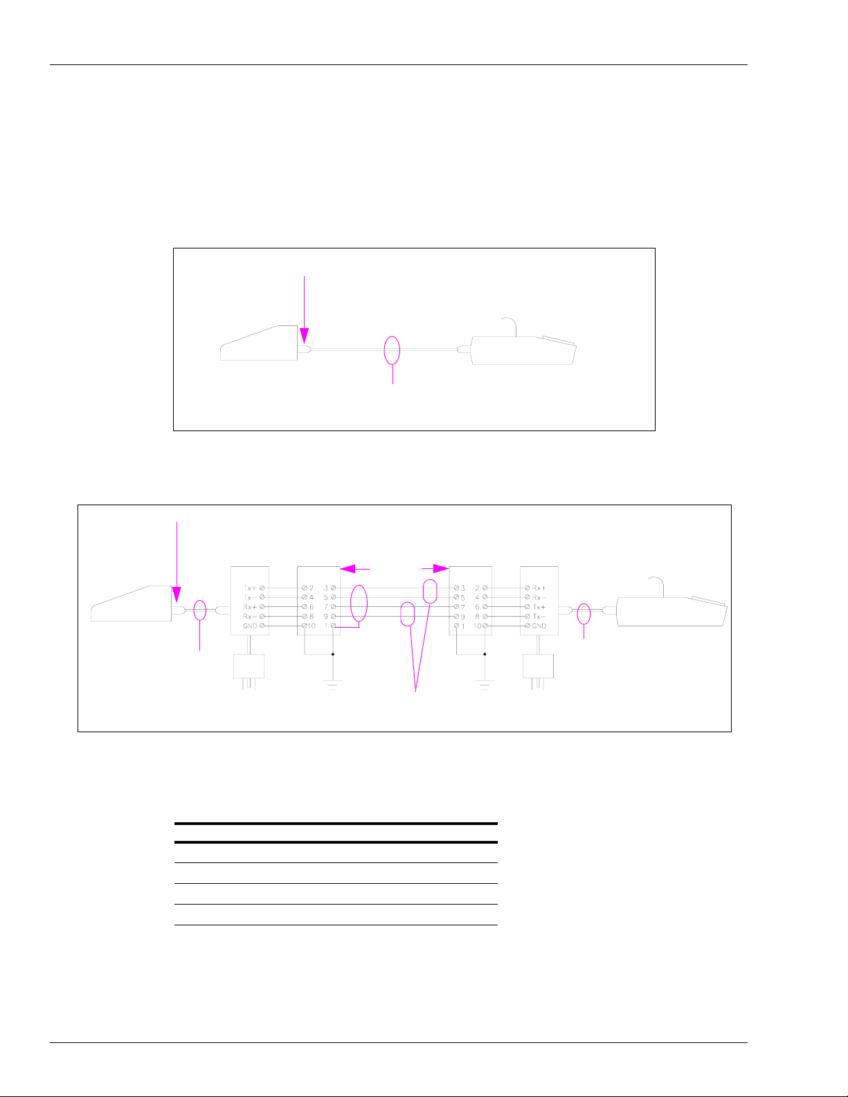
Figure 1-4: RS-232 Connection
KE200 Port 1 or 2
Peripheral Device
(Terminal or Modem)
EIA 1:1 Cable
P/N C04549
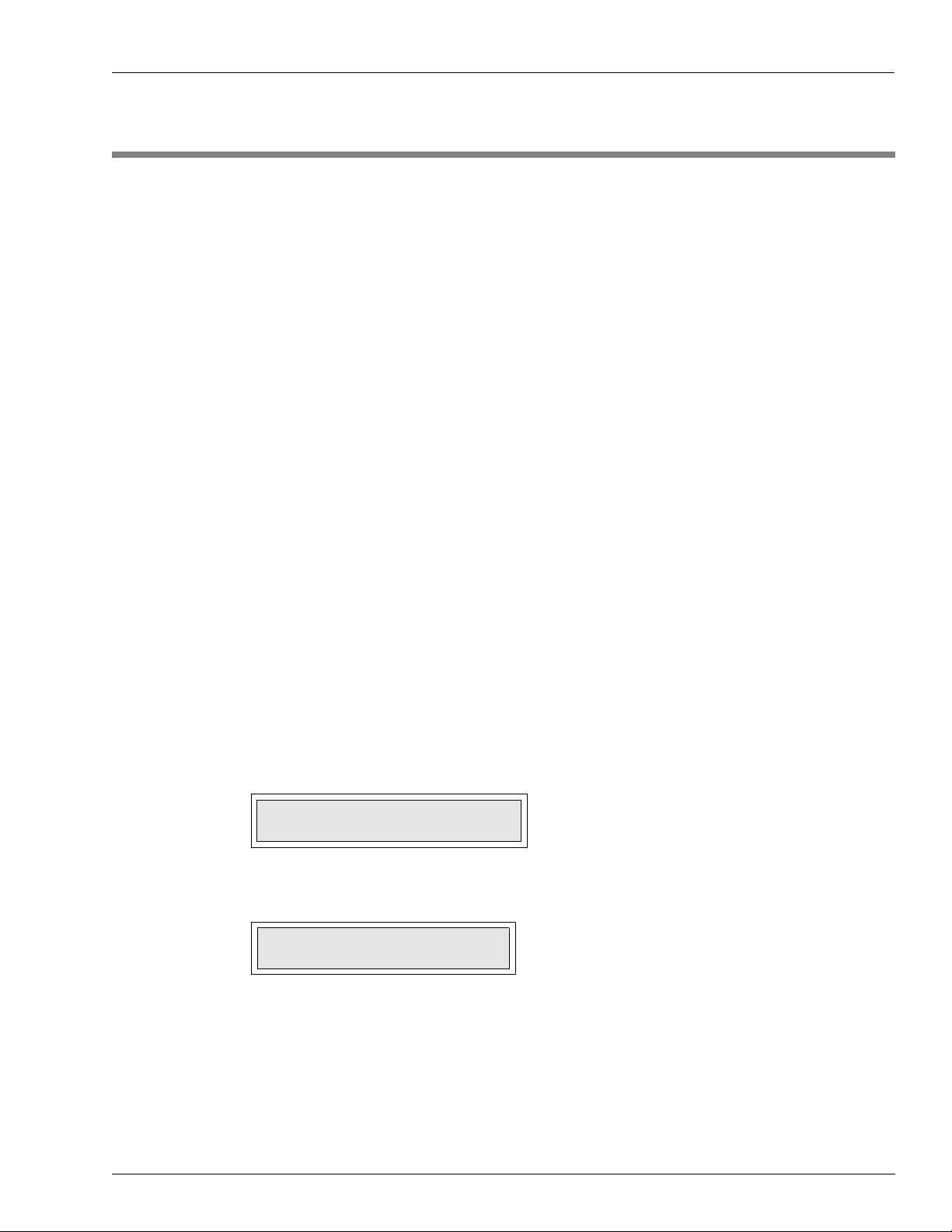
Figure 1-5: Short Haul Modem - ME800
KE200 Port 1 or 2
EIA 1:1 Cable
(P/N C04549)
SHM -ME800
(P/N C02479)
AC Power AC Ground
Protector
(P/N C08159)
Maximum
Distance
(see Note)
Shield
GND
(if used)
2 Twisted Pairs
(see Note)
Protector
(P/N C08159)
AC Ground
SHM -ME800
(P/N C02479)
Peripheral Device
EIA 1:1 Cable
(P/N C04549)
AC Power
Note: Maximum distances specified by the manufacturer are listed here. These distances are
valid when you use 22 AWG or 24 AWG two twisted-pair unshielded cable (a shielded
cable will reduce the distance to one-third of the values shown).
Baud Rate Distance
300 and 1200 baud 10 miles
2400 baud 5 miles
4800 baud 4 miles
9600 baud 2 miles
Page 8 MDE-4465A KE200 Key Encoder/Maintenance Terminal Operation Manual · October 2007
Page 15

Cables System Overview
Figure 1-6: RS-422 Gasboy Short Haul Modem
KE200
Port 1
P2
Cables
Field Wiring 1500 Feet Max.
Shield Ground
Port 1
AC Ground
Gasboy SHM
(P/N C05618)
AC Power
Peripheral Device
EIA 1:1 Cable
(P/N C04549)
The drawing below shows the pin-to-pin layout of the EIA 1:1 cable (Gasboy P/N C04549).
Figure 1-7: Pin-to-Pin Layout of EIA 1:1 Cable
Male Connector
100 Feet Max.
P/N C05758
Male Connector Male Connector
(Wire End View)
MDE-4465A KE200 Key Encoder/Maintenance Terminal Operation Manual · October 2007 Page 9
Page 16

System Overview Using the KE200 Keypad and Key Receptacle
Using the KE200 Keypad and Key Receptacle
The keypad for the encoder is simple, consisting of numeric keys 0-9, and the following keys:
Figure 1-8: KE200 Keypad and Receptacle
• ENTER transmits entered information to the encoder and allows you to move through the
prompts. It is also used to acknowledge and clear error or status messages.
• CLEAR clears the entry. It is used as a “NO” response to a verification prompt. When
pressed twice in encoding mode, it enters special field separators and supervisor entry
characters.
•F1 in Setup and Maintenance modes allows you to move to the next prompt. It is disabled
for Encoding mode.
• F2 in Setup and Maintenance modes allows you to move to the previous prompt. It is
disabled for Encoding mode.
• RESET in Encoding or Setup modes returns you to the first prompt in the group. It is
disabled in Edit mode.
• PREV in Encode mode returns you to the previously displayed prompt. If you are at the
first prompt in a group, you will exit to the Encode menu. In Setup or Maintenance modes,
it backs you out by group. Use the flow diagram in Section 2 to visualize the following:
If you are at FIELD SIZE, under the group SELECT ID FIELD and you press PREV
once, you return to SELECT ID FIELD. If you press PREV again, CONFIG ID MENU
displays. If you press PREV again, SETUP MENU displays.
• ENCODE in Encode mode skips any intermediate prompts, validates remaining
unentered data, and takes you immediately to the ENCODE KEY verification menu from
whatever prompt you were at. If errors exist in the unentered data, the system returns to
the prompt in error and displays RANGE ERROR.
•“A”, “B”, “C” selects maintenance category in Setup and Maintenance modes.
• A key receptacle on the right-hand side of the encoder face allows you to insert Fleetkeys
for encoding or maintenance updating.
Page 10 MDE-4465A KE200 Key Encoder/Maintenance Terminal Operation Manual · October 2007
Page 17

Using the KE200 Display System Overview
Using the KE200 Display
The display has some distinguishing characteristics that will help you determine what entry is
required. A flashing cursor at the end of a prompt indicates that the KE200 is waiting for input
from the keypad (0-9) or “A”, “B”, “C” keys. If there is no flashing cursor on an input prompt,
use the “F1” or “F2” keys to toggle between possible choices for that prompt. When you
encounter an error or status message, press ENTER to clear the message. In an error
condition, the KE200 displays the field in error for correction. In Encoding mode, you may see
the following special characters on the display: “~” for field separator and “*” for supervisor
entry . These are discussed later in Field Descriptions, ID Fields (see
page 23).
“Configure ID Fields” on
Using Your Logger Printout
When you have a logger (printer) attached to Port 2 of your KE200 system, all significant
events are recorded on this printout. The following events are logged: power-ups, sign-ons,
sign-offs, mode changes, setup and load commands, encode key commands, reset commands,
encode records (if you answered yes to LOG KEY DATA?) and maintenance transactions.
Each logger printout entry is set up the same. It contains where the command originated
(system, keypad, Port 1 or Port 3), the command or event, and a date/time stamp. A sample
logger printout is shown below.
Figure 1-9: Logger Printout
MDE-4465A KE200 Key Encoder/Maintenance Terminal Operation Manual · October 2007 Page 11
Page 18

System Overview System Access and Operating Modes
System Access and Operating Modes
To guard against unauthorized use, the KE200 system has two types of access keys:
• A manager key, which allows access to both the Encoding and Maintenance modes
• A maintenance key, which allows access to Maintenance modes only.
The key is inserted into the front of the encoder cabinet. It has three possible positions which
correspond to the system modes:
•Idle
• Maintenance
• Encode/Setup
The key position for each mode is shown in Figure 1-10. You can access the modes only when
the proper key is inserted and in the correct position.
Figure 1-10: Key Positions for Each Mode
When a data terminal is in use, the KE200 must be in Idle mode to enable operation of all the
commands. When the KE200 is a standalone, Idle mode has no function other than to display
the current date and time.
Maintenance mode allows you to view and update maintenance information on a key. All
maintenance is performed from the KE200; you cannot perform maintenance from the data
terminal.
Encode/Setup mode allows access to all system setup parameters and encoding fields . The key
must be in this position for you to set up your system from the KE200 or to encode keys from
the KE200.
Page 12 MDE-4465A KE200 Key Encoder/Maintenance Terminal Operation Manual · October 2007
Page 19

Before Proceeding System Overview
Before Proceeding
You can begin to set up the KE200 for operation, if you have a general understanding of how
the system works.
When you first use the system, you will have to perform setup functions to define your system
attributes, configure the maintenance table, set your units and date format, and run any
diagnostics that are required. The procedure for setting up the KE200 differs depending on
whether you are using the keypad or a data terminal.
With the keypad, you must progress through a series of displayed menus and fill in the data for
each. With the terminal, you can run a “SETUP” routine that automatically prompts you for
the data necessary to run your system, or you can execute commands individually.
The section “KE200 Setup - Standalone” on page 15 describes setting up the system using the
Standalone KE200. The section “KE200 Setup - Terminal” on page 35 describes setting up the
system using the data terminal.
Once your system is set up, you must encode your keys, based on your system layout and use
some of the values you entered in Setup mode. Once your keys are initially encoded, you will
have to access Encode mode infrequently, when you need to add additional keys, or change
data on a key. The section
encoding and encoding procedures for both the standalone KE200 and the data terminal.
“Encoding Keys” on page 63 contains general information on key
Finally, you will have to record Performed Maintenance as scheduled. The section
“Performing Maintenance” on page 77 describes viewing maintenance information on the key
and performing maintenance.
MDE-4465A KE200 Key Encoder/Maintenance Terminal Operation Manual · October 2007 Page 13
Page 20

System Overview Before Proceeding
This page is intentionally left blank.
Page 14 MDE-4465A KE200 Key Encoder/Maintenance Terminal Operation Manual · October 2007
Page 21
Overview KE200 Setup - Standalone
2 – KE200 Setup - Standalone
Overview
The standalone KE200 allows you direct access to all setup, encoding (numeric fields only),
and maintenance procedures. You must enter commands via the keypad and a series of menus
are displayed, which guide you through setup, encoding, and maintenance.
Accessing KE200 Modes
The different modes of the KE200 are determined by the position of the Manager’s key. When
the KE200 is standalone, Idle mode has no function, other than to display the current date and
time. Maintenance mode allows you to view and update maintenance information on a key.
Encode/Setup mode allows access to all system setup parameters and encoding fields. The key
must be in this position for you to set up your system from the KE200 or to encode keys from
the KE200.
Maintenance Mode (1000 FleetKey only)
Note: You can use either the Manager key or the Maintenance key to access Maintenance
mode.
To access Maintenance mode, proceed as follows:
1 Turn th e Manager key to MAINT. The system displays the following:
MAINTENANCE MODE:
PERFORM MAINTENANCE
2 Press ENTER to display the first Perform Maintenance prompt.
PERFORM MAINTENANCE:
INSERT KEY
MDE-4465A KE200 Key Encoder/Maintenance Terminal Operation Manual · October 2007 Page 15
Page 22

KE200 Setup - Standalone System Flow Diagram
Encode Mode
To access Encode mode, proceed as follows:
1 Turn th e Manager key to ENCODE. The system displays the following:
SELECT OPTION:
ENCODE
2 If you wish to encode keys, press ENTER. The system displays the following:
ENCODE MENU:
ENCODE KEY
Setup Mode
To access Setup mode, proceed as follows:
1 Turn th e Manager key to ENCODE. The system displays the following:
SELECT OPTION:
ENCODE
2 If you wish to enter Setup mode, press F1. The system displays the following:
SELECT OPTION:
SETUP
3 Press ENTER to display the first Setup prompt.
SETUP MENU:
LOAD DATE
System Flow Diagram
The KE200 Key Encoder/Maintenance Terminal software is designed to facilitate easy
navigation.
Page 16 MDE-4465A KE200 Key Encoder/Maintenance Terminal Operation Manual · October 2007
Figure 2-1 on page 17 shows the system layout by manager key position.
Page 23

System Flow Diagram KE200 Setup - Standalone
Figure 2-1: System Flow Diagram
MDE-4465A KE200 Key Encoder/Maintenance Terminal Operation Manual · October 2007 Page 17
Page 24

KE200 Setup - Standalone Setting Up the KE200
Setting Up the KE200
The first time you use your Key Encoder/Maintenance Terminal, perform the following steps
in order to load your system with the necessary data for processing.
1 With the Manager key inserted and in the idle position, turn the power switch, located on the
left side of the face to “ON”. The KE200 displays the current date and time (these were set at
the factory to Eastern time).
2 Perform the Reset Records command. See “Encoding Keys” on page 63 and “Reset Encode
Records - Keypad” on page 75.
3 Enter Setup mode and perform the following:
• Load Date (if not correct)
• Load Time (if not correct)
• Load Station ID for your key encoder/maintenance terminal.
• Load System ID: This must match the system ID of your FleetKey system. Refer to the
key layout provided with your FleetKey system.
• Load Working Key: This must match the working key of your FleetKey system. Refer to
the key layout provided with your FleetKey system.
• Load Country options.
• Configure ID fields: The fields you configure must match the fields as you ordered them.
Only numeric fields can be encoded using the KE200 keypad. If your ID fields are
alphanumeric (FleetKey only), you must use a data terminal for encoding input. Refer to
your key layout.
• Configure Maintenance Transactions (FleetKey only): This includes resetting the
transaction pointer, resetting the transaction file and loading the transaction number.
• Configure Maintenance table (FleetKey only): This includes clearing the Maintenance
Table to eliminate any data that may have been present from testing and loading a
Maintenance Table that matches the one defined in your FleetKey system.
• Run diagnostics, if necessary.
Once the above steps are performed, your system is ready to encode keys and record
Performed Maintenance.
The commands listed above are discussed on the pages that follow, in the order in which they
appear on the Setup menu.
Page 18 MDE-4465A KE200 Key Encoder/Maintenance Terminal Operation Manual · October 2007
Page 25

Load Date KE200 Setup - Standalone
Load Date
Use “LOAD DATE” to load the current date. The KE200 should be factory set with the correct
date, but occasionally you may need to change it.
To load date, proceed as follows:
1 Enter the Setup mode as described previously. The system displays the following:
SETUP MENU:
LOAD DATE
2 Press ENTER. The system displays the following:
3 Type the correct date and press ENTER. The display returns to the following:
Load Time
SETUP MENU:
The currently loaded date appears on the second line of the display.
MMDDYY
1 2 1 6 9 1
SETUP MENU:
LOAD DATE
To display another primary prompt, press F1 or F2 until the desired prompt appears.
To exit back to “SELECT OPTION: SETUP”, press PREV.
Use “LOAD TIME” to load the current time in 24-hour format (00:00 to 23:59). The KE200 is
factory set to Eastern time with the correct time, but occasionally you may need to change it.
To load time, proceed as follows:
1 Enter Setup Mode as described previously. The system displays the following:
SETUP MENU:
LOAD DATE
MDE-4465A KE200 Key Encoder/Maintenance Terminal Operation Manual · October 2007 Page 19
Page 26
KE200 Setup - Standalone Load Station ID
2 Press F1 or F2 until the following is displayed:
SETUP MENU:
LOAD TIME
3 Press ENTER. The prompt now reads:
LOAD TIME: HHMMSS
095521
The currently loaded time appears on the second line of the display.
4 Type the correct time and press ENTER. The display returns to the following:
SETUP MENU:
LOAD TIME
5 To display another primary prompt, press F1 or F2 until the desired prompt appears.
6 To exit back to “SELECT OPTION”, press SETUP > PREV.
Load Station ID
Use “LOAD STATION ID” to load a number of up to three digits to identify the key encoder/
maintenance terminal. This identifier is similar to the site ID used in the FleetKey system. It is
used mainly to identify the station for communication with PCs or other communications
equipment.
To load station ID, proceed as follows:
1 Enter Setup Mode as described previously. The system displays the following:
SETUP MENU:
LOAD DATE
2 Press F1 or F2 until the following appears:
SETUP MENU:
LOAD STATION ID
Page 20 MDE-4465A KE200 Key Encoder/Maintenance Terminal Operation Manual · October 2007
Page 27

Load System ID KE200 Setup - Standalone
3 Press ENTER. The currently loaded value appears on the second line of the display.
LOAD STATION ID:
000
4 Type a one to three digit identifier and press ENTER. The display returns to the following:
SETUP MENU:
LOAD STATION ID
5 To display another primary prompt, press F1 or F2 until the desired prompt appears.
6 To exit back to “SELECT OPTION”, press SETUP > PREV.
Load System ID
Use “LOAD SYSTEM ID” to load the 4-digit system ID of your FleetKey system. This
number is verified with the key when you perform maintenance.
To load system ID, proceed as follows:
1 Enter Setup Mode as described previously. The system displays the following:
SETUP MENU:
LOAD DATE
2 Press F1 or F2 until the following appears:
SETUP MENU:
LOAD SYSTEM ID
3 Press ENTER. The currently loaded value appears on the second line of the display.
SYSTEM ID:
5630
4 Type the system ID of your FleetKey system. This number appears on your key layout.
5 Press ENTER. The display returns to the following:
SETUP MENU:
LOAD SYSTEM ID
MDE-4465A KE200 Key Encoder/Maintenance Terminal Operation Manual · October 2007 Page 21
Page 28

KE200 Setup - Standalone Load Working Key
6 To display another primary prompt, press F1 or F2 until the desired prompt appears.
7 To exit back to “SELECT OPTION”, press SETUP > PREV.
Load Working Key
Use “LOAD WORKING KEY” to load the 4-digit working key used with your FleetKey
system. This number is used to encrypt and decrypt Personal Identification Numbers (PINs)
when you encode your keys.
To load working key, proceed as follows:
1 Enter Setup Mode as described previously. The system displays:
SETUP MENU:
LOAD DATE
2 Press F1 or F2 until the following appears:
SETUP MENU:
LOAD WORKING KEY
3 Press ENTER. The currently loaded value appears on the second line of the display.
LOAD WORKING KEY:
1234
4 Type the working key for your FleetKey system. This number appears on your key layout.
5 Press ENTER. The display returns to the following:
SETUP MENU:
LOAD WORKING KEY
6 To display another primary prompt, press F1 or F2 until the desired prompt appears.
7 To exit back to “SELECT OPTION”, press SETUP > PREV.
Page 22 MDE-4465A KE200 Key Encoder/Maintenance Terminal Operation Manual · October 2007
Page 29

Configure ID Fields KE200 Setup - Standalone
Configure ID Fields
Use “CONFIG ID FIELDS” to identify the number of ID fields and the name, size, and format
of each. The system has a set number of predefined field names (VEHICLE, EMPLOYEE,
TRAILER, EQUIPMENT, PATRON, S.S. NO., MISC, DRIVER, ACCOUNT, or
DEPARTMENT). You must choose one of these names. If you have a field that does not
exactly match one of these names, select one that is close or select “MISC”. ID fields used on
CFN systems with the key option must be numeric.
To configure ID fields , proceed as follows:
Number of ID Fields
1 Enter Setup Mode as described previously. The system displays:
SETUP MENU:
LOAD DATE
2 Press F1 or F2 until the following appears:
SETUP MENU:
CONFIG ID FIELDS
3 Press ENTER. The display prompts:
CONFIG ID MENU:
NO. OF ID FIELDS
4 To identify the number of ID fields, proceed to step 5. To edit/view ID fields, proceed to step
7.
5 Press ENTER. The currently loaded value appears on the second line of the display.
NO. OF ID FIELDS
2
6 Type the number of ID fields configured in your FleetKey system and press ENTER. The
display returns to the following:
CONFIG ID MENU:
NO. OF ID FIELDS
MDE-4465A KE200 Key Encoder/Maintenance Terminal Operation Manual · October 2007 Page 23
Page 30

KE200 Setup - Standalone Configure ID Fields
Edit or View Field Data
7 Press F1. The system displays the following:
CONFIG ID MENU:
EDIT/VIEW ID FIELD
8 Press ENTER. The system displays the following:
SELECT ID FIELD:
#1 EMPLOYEE,04,N
The second line of the display shows the current attributes of field 1 (number, name, size, and
format). If no data has been loaded for the field, the system displays “no data loaded...”.
9 To select data for a different ID field, press F1 or F2 until the desired field data is displayed.
10 To change one or more of the displayed field's attributes, press ENTER. The system prompts:
ID FIELD #1:
FIELD NAME
11 To change the field name, press ENTER. The currently loaded value appears on the second
line of the display.
FIELD NAME:
EMPLOYEE
12 Press F1 or F2 to scroll through the list of available field names. When the desired name is
displayed, press ENTER. The display returns to the following:
ID FIELD #1:
FIELD NAME
13 To change another field attribute, press F1. The system displays the following:
ID FIELD #1:
FIELD SIZE
Page 24 MDE-4465A KE200 Key Encoder/Maintenance Terminal Operation Manual · October 2007
Page 31

Configure ID Fields KE200 Setup - Standalone
14 To change the size (length) of the field, press ENTER. The currently loaded value appears on
the second line of the display.
FIELD SIZE:
40
15 Type the new field size and press ENTER. The display returns to the following.
ID FIELD #1:
FIELD SIZE
16 To change another field attribute, press F1 to display the following.
ID FIELD #1:
FIELD FORMAT
17 To change the format of the field (numeric or alpha), press ENTER.
Note: Fields used on CFN systems with the key option must be numeric.
The currently loaded value appears on the second line of the display.
FIELD FORMAT:
NUMERIC
18 Press F1 or F2 to toggle between choices. When the desired choice is displayed, press
ENTER. The system returns to “FIELD FORMAT”.
Note: Numeric ID fields can be set up as incrementing or decrementing fields to speed data
entry. However, these fields can only be encoded this way using the “LOAD FORMA T”
terminal command. See
19 To change the attributes for another field name, press PREV. The display returns to the
“Load Format (LO FO)” on page 42.
following:
SELECT ID FIELD:
#1 EMPLOYEE,04,N
Repeat the procedure from step 9 onwards.
20 To exit to the “EDIT/VIEW ID FIELD” prompt, press PREV twice.
21 To exit to the “SETUP MENU” prompt, press PREV thrice. Then press F1 to select another
primary prompt.
MDE-4465A KE200 Key Encoder/Maintenance Terminal Operation Manual · October 2007 Page 25
Page 32

KE200 Setup - Standalone Configure Maintenance Transactions (1000 FleetKey only)
Configure Maintenance Transactions (1000 FleetKey only)
“CONFIGURE MAINTENANCE TRANSACTIONS” is a menu item that provides access to
three submenus that allow you to reset the maintenance transaction pointer, reset the
transaction file, and load the starting transaction number for maintenance transactions.
Maintenance transactions are stored in the KE200 in circular memory storage. The system
keeps track of these transactions by a beginning (FIRST) and ending (LAST) pointer system.
The FIRST pointer is set with the “Reset Transaction Number” procedure. The LAST pointer
advances as transactions are stored. The KE200 stores 980 maintenance transactions. You can
print these transactions via the RS-232 port, or you can print only specific ones by moving the
FIRST pointer using the “Reset Transaction Pointer” procedure. Ensure that you replace the
pointer to its original location after printing the desired transactions. If you leave the pointer
ahead of transactions not yet printed, transactions may be overwritten and lost.
When the entire maintenance transaction file has been filled, a “MEMORY FULL” condition
exists. The KE200 will not accept new maintenance transactions until space has been freed up.
To free transaction space, first, print or poll the existing maintenance transactions. Then,
advance the FIRST transaction pointer using the reset transaction pointer procedure. This will
free space below the first pointer allowing new transactions to overwrite the old ones.
To configure Ma intenance Transactions, proceed as follows:
1 Enter Setup Mode as described previously. The system displays the following:
SETUP MENU:
LOAD DATE
2 Press F1 or F2 until the following appears:
SETUP MENU:
CONFIG MAINT TRANS
Reset Transaction Pointer
Use “RESET TRANS POINTER” to reset the starting point for printing maintenance
transactions via an RS-232 port. For example, if you have 50 transactions in the maintenance
transaction file (your ending pointer is at 50) and you want to print only the last 10
transactions, you will have to move your FIRST pointer to 40.
Note: Ensure that you return your pointer to its starting location to avoid losing transactions.
Page 26 MDE-4465A KE200 Key Encoder/Maintenance Terminal Operation Manual · October 2007
Page 33

Configure Maintenance Transactions (1000 FleetKey only) KE200 Setup - Standalone
To reset Transaction Pointer, proceed as follows:
1 From the “CONFIG MAINT TRANS” display, press ENTER. The system displays the
following:
MAINT TRANS MENU:
RESET TRANS POINTER
2 Press ENTER. The system displays the following:
RESET TRANS POINTER:
?
3 Type the number at which you want transactions to start and press ENTER.
Reset Transaction File
Use “RESET TRANS FILE” to reset the maintenance transaction file.
To reset Transaction file, proceed as follows:
1 From the “CONFIG MAINT TRANS” display, press ENTER. The system displays the
following:
MAINT TRANS MENU:
RESET TRANS POINTER
2 Press F1 until the system displays the following:
MAINT TRANS MENU:
RESET TRANS FILE
3 Press ENTER. The system displays the following:
ARE YOU SURE?
<ENT>=YES <CLR>=NO
4 Press ENTER to reset the file. The system displays the message “COMMAND
COMPLETED”.
MDE-4465A KE200 Key Encoder/Maintenance Terminal Operation Manual · October 2007 Page 27
Page 34

KE200 Setup - Standalone Configure Maintenance Table (1000 FleetKey only)
Load Transaction Number
Use “LOAD TRANS NUMBER” to load a starting number for your maintenance transactions.
To start your transactions at the number you desire, this command value must be set to the
number before the one you wish to start at (for example, if your first transaction is to be
number 1, set this command to zero).
To load Transaction number, proceed as follows:
1 From the “CONFIG MAINT TRANS” display, press ENTER. The system displays the
following:
MAINT TRANS MENU:
RESET TRANS POINTER
2 Press F1 until the system displays the following:
MAINT TRANS MENU:
LOAD TRANS NUMBER
3 Press ENTER. The currently loaded value appears on the second line of the display.
LOAD TRANS NUMBER:
0035
4 Type a 4-digit transaction number and press ENTER. The system returns to the following:
MAINT TRANS MENU:
LOAD TRANS NUMBER
5 To exit to the “SETUP MENU” prompt, press PREV, then press F1 to select another primary
prompt.
Configure Maintenance Table (1000 FleetKey only)
“CONFIG MAINTENANCE TABLE” is a menu item that provides ac cess to two submenus
which allow you to load the maintenance table or clear the maintenance table. As discussed in
detail in the FleetKey Operation Manual, the Maintenance table consists of up to 20 classes of
vehicle, with the three maintenance types (A, B, and C) and a “MILES” and “DAYS” between
maintenance entry defined for each. The maintenance table you enter at the KE200 Encoder
must be identical to the one entered at the FleetKey system.
Use “CLEAR MAINT TABLE” when you start up your system or before the initial loading of
the maintenance table to clear out any leftover information that may be present from factory
testing. Use the “CLEAR” option with care as it deletes the entire maintenance table and loads
it with zeros.
Page 28 MDE-4465A KE200 Key Encoder/Maintenance Terminal Operation Manual · October 2007
Page 35

Configure Maintenance Table (1000 FleetKey only) KE200 Setup - Standalone
To configure Maintenance Table, proceed as follows:
Build a Maintenance Table
1 Enter Setup Mode as described previously. The system displays the following:
SETUP MENU:
LOAD DATE
2 Press F1 or F2 until the following appears:
SETUP MENU:
CONFIG MAINT TABLE
3 Press ENTER. The system prompts:
MAINT TABLE MENU:
LOAD MAINT TABLE
If you wish to load a maintenance table, press ENTER. The system prompts:
VEH. CLASS (1-20):
10
4 Enter the class you wish to define and press ENTER (to define data for class “1”, just press
ENTER). The system displays:
VEHICLE CLASS #01:
A: M=010000 D=000
Line 2 contains the current data for maintenance type A (miles and days).
5 If you wish to display data for another maintenance type (B or C), press F1 or F2. When the
desired maintenance type data is displayed, press ENTER. The system displays:
MAINTENANCE x:
MILES
MDE-4465A KE200 Key Encoder/Maintenance Terminal Operation Manual · October 2007 Page 29
Page 36

KE200 Setup - Standalone Configure Maintenance Table (1000 FleetKey only)
6 To enter miles, press ENTER. The currently loaded value appears on the second line of the
display:
MILES:
010000
7 Enter up to six digits to represent the number of miles between maintenance (for example, if
maintenance “A” is to be performed every 10,000 miles, enter 10000) and press ENTER. The
display returns to:
MAINTENANCE x:
MILES
8 To enter days, press F1 and ENTER. The system displays the following:
DAYS:
000
The currently loaded value appears on the second line of the display.
9 Enter up to three digits to represent the number of days between maintenance (for example, if
maintenance “A” is to be performed every 60 days, enter 60) and press ENTER. The display
returns to:
MAINTENANCE A:
DAYS
10 To define data for another maintenance type, press PREV and repeat this procedure from step
5 onwards.
11 To define maintenance types for another class, press PREV twice and repeat this procedure
from step
12 To return to the “SETUP MENU” display, press PREV four times.
4 onwards.
Clear the Maintenance Table
To clear the maintenance table, proceed as follows:
1 Enter Setup Mode as described previously. The system displays the following:
SETUP MENU:
LOAD DATE
Page 30 MDE-4465A KE200 Key Encoder/Maintenance Terminal Operation Manual · October 2007
Page 37

Load Country Options KE200 Setup - Standalone
2 Press F1 or F2 until the following appears:
SETUP MENU:
CONFIG MAINT TABLE
3 Press ENTER. The system prompts:
MAINT TABLE MENU:
LOAD MAINT TABLE
4 Press F1 or F2 until the system prompts:
MAINT TABLE MENU:
CLEAR MAINT TABLE
5 To clear the maintenance table, press ENTER. The system prompts you with the following
query:
ARE YOU SURE?
<ENT>=YES <CLR>=NO
6 To clear the maintenance table, press ENTER. To leave the maintenance table unchanged,
press CLEAR. The display returns to the following:
MAINT TABLE MENU:
CLEAR MAINT TABLE
7 To return to the “SETUP MENU”, press PREV.
Load Country Options
Use “LOAD COUNTRY OPTIONS” to enter the units of measure (miles or kilometers) and
the date format to be used (MM/DD/YY, YY/MM/DD, or DD/MM/YY). The date format you
select will show up in Idle mode, in encoding records, in maintenance transactions, or when
you are viewing maintenance.
MDE-4465A KE200 Key Encoder/Maintenance Terminal Operation Manual · October 2007 Page 31
Page 38

KE200 Setup - Standalone Load Country Options
To load Country options, proceed as follows:
1 Enter Setup mode as described previously. The system displays the following:
SETUP MENU:
LOAD DATE
2 Press F1 or F2 until the following appears:
SETUP MENU:
LOAD COUNTRY OPTIONS
3 Press ENTER. The system displays the following:
COUNTRY OPTIONS:
UNITS
4 To enter units, press ENTER. The system displays the following:
UNITS:
MILES
5 Press F1 to toggle between miles and kilometers. When the desired choice displays, press
ENTER. The display returns to the following:
COUNTRY OPTIONS:
UNITS
6 To enter the date format, press F1. The system displays the following:
COUNTRY OPTIONS:
DATE FORMAT
7 Press ENTER. The system displays the following:
DATE FORMAT:
MM/DD/YY
8 Press F1 to toggle between “MM/DD/YY”, “YY/MM/DD”, or “DD/MM/YY”. When the
desired choice appears, press ENTER. The display returns to “COUNTRY OPTIONS: DATE
FORMAT”.
9 To return to the “SETUP MENU”, press PREV.
Page 32 MDE-4465A KE200 Key Encoder/Maintenance Terminal Operation Manual · October 2007
Page 39

Diagnostics KE200 Setup - Standalone
Diagnostics
The KE200 Key Encoder/Maintenance Terminal contains six diagnostics:
• RAM Test - tests RAM
• ROM Test - tests ROM
• Keypad Test - tests keypad
• Display Test - tests display
• Key Read Totalizers - displays number of keys read or written to
• Program Version - provides program version information and program date
To access any of the diagnostics, proceed as follows:
1 Enter Setup mode as described previously. The system displays the following:
SETUP MENU:
LOAD DATE
2 Press F1 or F2 until the system displays the following:
SETUP MENU:
DIAGNOSTICS
3 Press ENTER. The system displays the first diagnostic test.
DIAGNOSTICS MENU:
RAM TEST
To perform a RAM test, skip to step 4. To perform another test, skip to step 5.
4 Press ENTER. The message “RAM PASSED” or “RAM FAILED” appears.
5 To select another diagnostic, press F1 or F2 to display the available choices. When the desired
diagnostic appears, press ENTER.
Note: If you select “KEYPAD TEST”, press the keys on the face of the unit and verify that they
match the displayed key name. To exit from the keypad test, press ENTER twice.
MDE-4465A KE200 Key Encoder/Maintenance Terminal Operation Manual · October 2007 Page 33
Page 40

KE200 Setup - Standalone Diagnostics
This page is intentionally left blank.
Page 34 MDE-4465A KE200 Key Encoder/Maintenance Terminal Operation Manual · October 2007
Page 41

Using the Terminal KE200 Setup - Terminal
3 – KE200 Setup - Terminal
Using the Terminal
Using the data terminal to set up the KE200 and Encode keys is different and easier compared
to setting up and encoding from the keypad. Ensure that the manager's key on the KE200 is in
the Idle position. You do not have to switch between modes when using the terminal.
Commands at the data terminal are keyed in directly, eliminating the need for menus. Once
you begin running the system, you will quickly memorize the necessary commands. If needed,
a special HELP command is available which lists the commands and their abbreviations.
When setting up the system, the terminal command set includes a “SETUP” command, which
automatically prompts you for the setup data. Alternatively, you can execute commands
individually.
When encoding, using the terminal speeds up the input by allowing you to load and use stored
encoding formats. These formats allow you to enter field type specifiers and values that will
automatically increment, decrement, or keep a field constant as you proceed through your
encoding operation. See the
Entering Commands and Input
At the data terminal, you must key in commands at the asterisk prompt. In the procedures for
Terminal mode, the short form of the command is shown in uppercase letters. However, you
can type whole or partial words to run the commands and you can use either uppercase or
lowercase letters.
Load commands have various possible values contained in “< >” brackets after the command.
The system also displays the current value of the command. You can press ENTER to accept
the displayed value or type a different one.
You can abort the running of any command by pressing the CTRL and C keys. The KE200
supports “X-ON/X-OFF” protocol for halting data transmission. To halt or suspend data from
being transmitted, issue an “X-OFF” command by pressing the CTRL and S keys. To resume
data transmission, issue the “X-ON” command by pressing the CTRL and Q keys. The KE200
also supports the more command pipe (for example, “PR FO | more”). To resume data display
after a “more” command, press any key.
“Load Format (LO FO)” on page 42 for details.
MDE-4465A KE200 Key Encoder/Maintenance Terminal Operation Manual · October 2007 Page 35
Page 42

KE200 Setup - Terminal Signing On to the Terminal
You may make a mistake when you enter commands and data. If you need to delete text, you
can use backspace to move the cursor to the error and type over to correct it, or you can press
the delete key repeatedly to back the cursor up to the error location. When you use the delete
method, the system inserts a slash and prints the characters in reverse order from the way they
were entered. When you reach the error location, press the correct character. The system
inserts another slash and you can continue typing the correct string. For example, if you typed
“PRUNT DATE”, pressing delete repeatedly back to the error and then typing the correct
string will display text similar to the following:
Signing On to the Terminal
Once your data terminal is connected to the KE200, or your phone modems are in place, you
can communicate with your system. T o guard against unauthorized access, the system requires
a sign-on password before you can enter commands on the system.
To sign on to the terminal, proceed as follows:
1 Turn on the power to your data terminal.
2 If you are using phone modems, dial and establish a connection with the site modem. If you
are using a computer, follow the instructions of your interface program.
3 The system should display “SIGN ON:”. If it does not, press RETURN. “SIGN ON:” will
then appear.
4 Type a 1 to 16-character alphanumeric password and press RETURN. The password is not
displayed as you type it. When the correct password is entered, an asterisk prompt (*) appears
and you can enter commands.
If you are signing on for the first time, the password is “GASBOY”, which needs to be typed
in uppercase.
To change the password, use the “LOad SIgn-on” command.
If you enter the password incorrectly, the system returns to the “SIGN ON:” prompt. Repeat
4.
step
Page 36 MDE-4465A KE200 Key Encoder/Maintenance Terminal Operation Manual · October 2007
Page 43

Signing Off of the Terminal KE200 Setup - Terminal
Signing Off of the Terminal
To sign off from the terminal, type EXIT and press ENTER.
The data terminal for KE200 communication is set to a 5 minute time-out. This means that if
the terminal does not register any input for 5 minutes, it automatically signs off.
Lost or Forgotten Password
If you forget your sign-on password , the KE200 system provides a way for you to gain system
access.
1 Place the manager’s key in the “ENCODE” position.
2 At the “SIGN ON:” prompt, type “GASBOY” and press ENTER. The asterisk prompt
appears.
3 Re-load your sign-on password using the “LOAD SIGNON” command.
Setting Up the KE200
The first time you use your Key Encoder/Maintenance Terminal, you must perform the
following steps in order to load your system with the necessary data to perform your
processing:
1 With the Manager key inserted and in the idle position, turn the power switch located on the
left side of the face to “ON”. The KE200 displays the current date and time (these were set at
the factory to Eastern time).
2 Sign on to the terminal as described in “Signing On to the Terminal” on page 36.
3 At the asterisk command prompt, use the “LO SI” command to load your sign-on code
(password) if you have not already done so.
4 Type “SETUP” and pre ss ENTER. “SETUP” is a batch program containing all commands
needed to load the KE200 for operation. Some commands are not included; see the
page 58 for details. If desired, you can also run all the load commands manually. The
commands to be run are:
- “LO DA”, loads date and time
- “LO SY”, loads the system ID. This must match the system ID of your FleetKey system.
- “LO ST”, loads the station ID.
- “LO PI”, loads the working key (for pin calculation). This must match the working key
of your FleetKey system.
- “LO CO”, loads country options for units and date format.
“Setup” on
MDE-4465A KE200 Key Encoder/Maintenance Terminal Operation Manual · October 2007 Page 37
Page 44

KE200 Setup - Terminal Clear Maintenance (CL MA) (1000 FleetKey only)
- “LO ID”, loads ID fields. The fields you configure must match the fields as you ordered
them. Consult your key layout.
- “LO FO”, loads formats for key encoding.
- “RES RE”, resets encoding records file.
- “RES TR”, resets maintenance transaction file.
- “LO TR”, loads the starting transaction number.
- “CL MA”, clears the maintenance table (1000 FleetKey only).
- “LO MA”, loads the maintenance table. This table must match the one defined in your
FleetKey system. (1000 FleetKey only).
Once the above steps are performed, your system is ready to encode keys and record
performed maintenance.
The following pages contain all terminal commands, in alphabetical order.
The symbol “↵” is shown in examples to denote that the “ENTER” key is pressed.
Clear Maintenance (CL MA) (1000 FleetKey only)
Use “CLEAR MAINTENANCE” when you start up your system or before the initial loading
of the maintenance table to clear out any residual information that may be present from factory
testing. Use the “CL MA” option with care as it deletes the entire maintenance table and loads
it with zeros.
To clear the maintenance table, proceed as follows:
1 At the asterisk prompt, type “CL MA” and press ENTER. The system responds with the
message, “CLEAR MAINTENANCE TABLE? <Y OR N>:”.
2 Type “Y” to clear or “N” not to clear and press ENTER. The system displays the message,
“COMMAND COMPLETED”.
Encode Key (EN KE)
Encoding your keys involves taking all the information you want on the key (from the
encoding form) and electronically writing it onto each key.
There are two methods for encoding: Formatted Encode and Unformatted Encode. A
Formatted Encode uses the field values loaded with the “LOAD FORMAT” command. An
Unformatted Encode prompts for every field and you must enter a value for each.
Page 38 MDE-4465A KE200 Key Encoder/Maintenance Terminal Operation Manual · October 2007
Page 45

Encode Key (EN KE) KE200 Setup - Terminal
Sometimes you will have to enter special characters into a field: field separators, and
supervisor entry fields. Field separators are represented by a tilde “~” character and are used
mainly during dual key encoding. Supervisor entry fields are represented by an asterisk “*”
and are used when encoding supervisor key fields.
To encode the key, proceed as follows:
1 Type “EN KE” and press ENTER. The system responds with the message, “FORMATTED
ENCODE? <Y OR N>:”
2 Type “Y” if you want to encode using the formats loaded with the “LOad FOrmat” command,
or “N” to override the formats and enter data for each field. Press ENTER. The system
prompts: “DISPLAY KEY DATA? <Y OR N>:”.
3 Type “Y” to display data on the terminal for the key upon completion of encoding or “N” not
to display the data. The system prompts: “LOG KEY DATA? <Y OR N>:”.
4 Type “Y” to print (on the logger) key field headings and key data for all keys encoded during
this session or “N” not to log the data. The system prompts “KEY TYPE?”.
5 Type the key type you wish to encode and press ENTER. The system responds with the first
prompt for that key type (this prompt will vary depending on whether you are doing a
Formatted or Unformatted Encode).
The system displays prompts until all key fields contain data, then displays the message,
“ENCODE KEY? <Y OR N>”.
6 To encode the key, type “Y” and press ENTER. The system displays the message, “INSERT
KEY”.
7 Insert the key into the KE200 receptacle and turn to the right. The system displays the
following message:
“ENCODING KEY #xxxxx...COMPLETED
REMOVE KEY”.
8 Remove the key. If you replied “Y” to “DISPLAY KEY DATA”, the data is displayed on your
terminal.
Note: The data you may have entered for the Previous Odometer and Last Odometer fields
will appear next to PREVIOUS ODOM (2) and LAST ODOM (2) in the display.
If you replied “Y” to “LOG KEY DATA”, a logger entry is made. The “KEY TYPE” prompt
reappears.
A sample logger entry is shown below:
9 Repeat this process from step 5 onwards to encode additional keys.
10 Press ENTER to exit to the asterisk prompt.
MDE-4465A KE200 Key Encoder/Maintenance Terminal Operation Manual · October 2007 Page 39
Page 46

KE200 Setup - Terminal Exit (EX)
Exit (EX)
Use “EXIT” to sign off of the terminal.
At the asterisk prompt, type “EX” and press ENTER. You are now signed off of the KE200.
Help (HE)
Use “HELP” to display a list of all terminal commands.
At the asterisk prompt, type “HE” and press ENTER. The system displays the following:
Load Country (LO CO)
Use “LOAD COUNTRY” to enter the units of measure (miles or kilometers) and the date
format to be used (MM/DD/YY, YY/MM/DD, or DD/MM/YY). The date format you select
will show up in Idle mode, in encoding records, in maintenance transactions, or when you are
viewing maintenance.
Page 40 MDE-4465A KE200 Key Encoder/Maintenance Terminal Operation Manual · October 2007
Page 47

Load Date (LO DA) KE200 Setup - Terminal
To enter units of measure and the date format, proceed as follows:
1 At the asterisk prompt, type “LO CO” and press ENTER. The system responds with the
message: “UNITS? <M=MILES, K=KILOMETERS>”.
2 Press ENTER to accept the current setting or type an alternate setting and press ENTER. The
system responds, “DATE FORMAT? <M=MM/DD/YY, Y=YY/MM/DD, D=DD/MM/YY>”.
Load Date (LO DA)
Use “LOAD DATE” to load the current date and time. The KE200 should be factory set with
the correct date. However, you may have to change it occasionally.
The system validates the month, day, and year together, so if you type an invalid month, day,
or year, you will not be notified until you have typed in values for all three fields. Hours and
minutes are entered in 24-hour format (00:00 to 23:59) and are validated together. If you type
an invalid value for hours, you will not be notified until after you type a value for minutes.
To load date, proceed as follows:
1 At the asterisk prompt, type “LO DA” and press ENTER. The system responds: “MONTH?”
2 Type a valid month and press ENTER. The system responds: “DAY?”
3 Type a valid day and press ENTER. The system responds: “YEAR?”
4 Type a valid year and press ENTER. The system responds “HOUR?”
5 Type a valid hour (in 24-hour format) and press ENTER. The system responds: “MINUTE?”
6 Type the valid minutes and press ENTER.
MDE-4465A KE200 Key Encoder/Maintenance Terminal Operation Manual · October 2007 Page 41
Page 48

KE200 Setup - Terminal Load Format (LO FO)
Load Format (LO FO)
“Load Format” allows you to load predefined formats for each key type. During encoding, you
can use these formats as a template to speed up encoding of your keys. Each format contains
all possible fields (except System ID) that can be on a key. Data for the system ID field is
obtained from the “LOAD SYSTEM” command.
Each format prompt consists of two parts: the field name, and a bracketed list of formatting
choices (specifiers) for that field. The system lists only specifiers that are relevant to that field.
A chart of specifiers and the applicable fields is provided below.
Key Types
Key Fields
Key Number
Alpha ID Fields
Numeric ID Fields V, C, I, D V, C, F, I, D, S V, C, F, I, D, S V, C, I, D, S
Exp. Date V, C V, C, F V, C, F V, C
Prod. Limit V, C F V, C V, C
Prod. Auth. V, C F V, C V, C
Price Level V, C V, C, F V, C, F V, C
Check Digit V, C V, C V, C V, C
Prev. Odom. V, C F V, C V, C
Last Odom. V, C F V, C V, C
Reas. Chk Dig. V, C F V, C V, C
Odom. Retries V, C F V, C V, C
Min. Miles V, C F V, C V, C
Max. Miles V, C F V, C V, C
Veh. Class V, C F V, C V, C
Maint A Odom. V, C F V, C V, C
Maint A Date V, C F V, C V, C
Maint B Odom. V, C F V, C V, C
Maint B Date V, C F V, C V, C
Maint C Odom. V, C F V, C V, C
Maint C Date V, C F V, C V, C
PIN V, C, I, D V, C, I, D V, C, I, D V, C, I, D
1
2
0, 4, 5, 6, 7 Key Type 1 Key Type 2 Key Type 3
V, I, D V, I, D V, I, D V, I, D
V, C V, C, F, S V, C, F, S V, C, S
V =Variable, field will be entered during encoding.
C =Constant, value is entered into format and used in all formatted encodes.
I =Incrementing, value is entered into format and increased by one for each key encoded.
D =Decrementing, value is entered into format and decreased by one for each key encoded.
F =Field separator, field defined on another key type (Key types 1 & 2 only).
S =Supervisor, field is a supervisor entry (Key types 1, 2, and 3 only).
1 = The Key Number field is not used by the CFN system, but it needs to be encoded. Set it up
as an incrementing field.
2 = The CFN system does not support alphanumeric ID fields.
Page 42 MDE-4465A KE200 Key Encoder/Maintenance Terminal Operation Manual · October 2007
Page 49

Load Format (LO FO) KE200 Setup - Terminal
The only key fields that can be formatted as incrementing or decrementing are key number,
numeric ID fields, or the PIN field. When you set a base number (“VALUE”) for an
incrementing/decrementing field, that value is used for all key types. If you change this field
value for one key type, the value is changed for all key types.
There are two types of key fields: Fixed fields, which are standard on all keys, and Variable ID
fields (numeric or alphanumeric), which must match those ordered with your FleetKey
system. On all Fixed fields and Numeric ID fields, the system affixes leading zeros to any
number you type in. On Alphanumeric ID fields, the system adds spaces from the end of your
entry to the end of the field.
Certain key types do not use every key field (for example, delivery keys do not need product
limit or product authorization). These fields must still contain a value, even though they are
not used. If you are encoding a key type that does not use a certain field, encode the field as
“C” (constant) and assign a value of zero. Do not enter zeros for dual key fields, when the field
in question appears on the other key. In this case, use field separators. The chart below shows
the fields that are encoded for each key type and those that can be encoded as constants with a
value of 0.
CFN 0-3CFN
Key Type 0 1 2 3 4 5 6 7
Key Number X X X X X X X X C C C
Alpha ID Fields X X X X CAN BE ENCODED WITH
Numeric ID Fields X X X X X X X
Exp. Date X X X X X X X X X X X
Prod. Limit X X X X C C C C X C C
Prod. Auth. X X X X C C C C X C C
Price Level X X X X C C C C X C C
Check Digit X X X X X X X X X C C
Prev. Odom. X X X X C C C C X C C
Last Odom. X X X X C C C C X C C
Reas. Chk Dig.1 X X X X C C C C X C C
Odom. Retries1 X X X X C C C C X C C
Min. Miles1 X X X X C C C C X C C
Max. Miles1 X X X X C C C C X C C
Veh. Class1 X X X X C C C C C C C
Maint A Odom. 2 X X X X C C C C C C C
Maint. A Date2 X X X X C C C C C C C
Maint. B Odom. 2 X X X X C C C C C C C
Maint .B Date2 X X X X C C C C C C C
Maint. C Odom. 2 X X X X C C C C C C C
Maint. C Date2 X X X X C C C C C C C
PIN X X X X X X X X X C C
Key:
X=Encode, C=Encode as constant with a value of zero, N/A = Not available with CFN system with key option.
VALUES OR AS CONSTANT
WITH A VALUE OF ZERO.
N/A N/A N/A
CFN
4,5
6
MDE-4465A KE200 Key Encoder/Maintenance Terminal Operation Manual · October 2007 Page 43
Page 50

KE200 Setup - Terminal Load IDFIELDS (LO ID)
Notes:1) If “Reas. Chk Dig.” is 0, you can encode zeros in odom retri es and min /max miles as
long as you are not using the maintenance option. If you are using the maintenance
option, you must encode values in min/max miles. Minimum miles can be zero.
2) If you are not using the maintenance option, encode as constant with a value of zero.
To use the “LOAD FORMAT” command, proceed as follows:
1 At the asterisk prompt, type “LO FO” and press ENTER. The system responds: “KEY
TYPE?”.
2 Type a key type from “0” to “7” and press ENTER. Key type values are:
0 Single Key 4 Delivery Key
1 Employee Key 5 Dipstick Key
2 Vehicle Key 6 Password Key (FleetKey), Code Key (CFN)
3 Supervisor Key 7 Encoding Key (FleetKey only)
3 Once you enter a key type, the system prompts you for all possible key fields. You will first
have key number, fol lowed b y y our variable ID fields and then the rest of the key fields. Each
field must contain a valid value. When you complete the last key field (PIN), the prompt
“KEY TYPE?” reappears so you can define the format for another key type.
4 To define another key type, type the number and press ENTER. To exit the “LOAD
FORMAT” command, press ENTER at the “KEY TYPE?” prompt.
Load IDFIELDS (LO ID)
Use “LOAD IDFIELDS” to identify the number of ID fields, and the name, size, and format of
each. The system provides up to 20 characters of variable identification fields (19 for CFN);
you can customize the system to your particular information requirements. The names and
sizes of these variable fields were specified at the time your FleetKey system was ordered.
You can have any combination of fields totaling up to 20 characters, but the maximum number
of separate fields is eight. Refer to the key layout provided with your FleetKey system for your
ID field definitions. For more information on ID fields, refer to
page 64 in the Encoding Keys section.
“Field Descriptions” on
Page 44 MDE-4465A KE200 Key Encoder/Maintenance Terminal Operation Manual · October 2007
Page 51

Load IDFIELDS (LO ID) KE200 Setup - Terminal
To use the “LOAD IDFIELDS” command, proce ed as follows:
1 At the asterisk prompt, type “LO ID” and press ENTER. The system responds: “NO OF ID
FIELDS?”.
2 Type the number of ID fields for your FleetKey system and press ENTER. The system
displays a chart containing the ID fields and their current values.
The system then prompts: “FIELD NO?”
3 Type the number of the ID field you wish to define and press ENTER. The system responds
with the prompt: “FIELD NAME?”
4 Type a 1 to 12-digit name for the field. The name you enter must match the one on your
FleetKey system. Press ENTER. The system responds: “FIELD SIZE? <1-20>”.
5 Type the field size (1 to 20; {limited to 19 numeric for CFN}) and press ENTER. The field
size must be the same as that specified for this field on your FleetKey system. The system
responds: “FIELD FORMAT? <A=ALPHA, N=NUMERIC>”.
6 Type “A” or “N” for your field format and press ENTER. You have now completed definition
for one ID field. The system responds: “FIELD NO?”.
7 Repeat this procedure from step 3 to define additional ID fields. If you have defined all your
ID fields, press ENTER to exit to the asterisk prompt.
MDE-4465A KE200 Key Encoder/Maintenance Terminal Operation Manual · October 2007 Page 45
Page 52

KE200 Setup - Terminal Load Maintenance (LO MA) (1000 FleetKey only)
Load Maintenance (LO MA) (1000 FleetKey only)
Use “LOAD MAINTENANCE” to load the maintenance table. As discussed in the FleetKey
Operation Manual, the maintenance table consists of up to 20 classes of vehicle, with the three
maintenance types (A, B, and C) and a “MILES” and “DAYS” between maintenance entry
defined for each. The maintenance table you enter onto the KE200 must be identical to the one
entered at the FleetKey system.
To use Load Maintenance to load the maintenance table, proceed as follows:
1 At the asterisk prompt, type “LO MA” and press ENTER. The system responds with the
prompt: “CLASS?”.
2 Type the first class (1-20) to be defined and press ENTER. The system responds:
“MAINT A
MILES? 000000”
3 Type the number of miles to elapse until maintenance is due for that class and press ENTER.
The system responds with the prompt: “DAYS?”.
4 Type the number of days to elapse until maintenance is due for that class and press ENTER.
The system then prompts for miles and days for maintenance types “B” and “C”.
5 Repeat steps 3 and 4 for each maintenance type. As each class is defined, the system prompts
for the next class. Repeat the procedure from step 2 to 4 define each new class.
6 Press ENTER to exit to the asterisk prompt.
Page 46 MDE-4465A KE200 Key Encoder/Maintenance Terminal Operation Manual · October 2007
Page 53

Load PIN (LO PI) KE200 Setup - Terminal
Load PIN (LO PI)
Use “LOAD PIN” to load the 4-digit working key used with your FleetKey system. This
number is used to encrypt and decrypt Personal Identification Numbers (PINs) when you
encode your keys. See the key layout provided with your FleetKey system to find your
working key.
To use Load PIN to load the 4-digit working key, proceed as follows:
1 At the asterisk prompt, type “LO PI” and press ENTER. The system responds “WORKING
KEY? 0000”.
2 Type the four digit working key ensuring that it matches the one used at your FleetKey system,
and press ENTER.
Load Signon (LO SI)
Use “LOAD SIGNON” to load the password you will use to sign on to the KE200 terminal.
Passwords can be up to 16 alphanumeric characters and are case sensitive. When signing on to
the system, you must type the password exactly as you loaded it.
To use Load Signon to load the password, proceed as follows:
1 At the asterisk prompt, type “LO SI” and press ENTER. The system responds: “SIGNON
CODE?”.
2 Type a 1 to 16-character password and press ENTER. You will not see the password you
enter. The next time you use the system, you must use this password to sign on.
MDE-4465A KE200 Key Encoder/Maintenance Terminal Operation Manual · October 2007 Page 47
Page 54

KE200 Setup - Terminal Load Station (LO ST)
Load Station (LO ST)
Use “LOAD STATION” to load the 3-digit numeric station number of the KE200. This
identifier is similar to the site ID used in the FleetKey system and is used to identify the station
for communication with PCs or other communications equipment.
To use Load Station to load the 3-digit numeric station number of the KE200, proceed as
follows:
1 At the asterisk prompt, type “LO ST” and press ENTER. The system responds with the
prompt: “STATION ID? xxx”.
2 Type the 3-digit station ID and press ENTER.
Load System (LO SY)
Use “LOAD SYSTEM” to load the four digit system ID of your FleetKey system. This
number is verified with the key when you perform maintenance.
To use Load System to load the four digit system ID of your FleetKey system, proceed as
follows:
1 At the asterisk prompt, type “LO SY” and press ENTER. The system responds with the
prompt: “SYSTEM ID?”.
2 Type your four digit system ID and press ENTER. This number must match the system ID
assigned to your FleetKey system. If you are unsure of your system ID, consult your custom
key layout provided with your FleetKey system.
Page 48 MDE-4465A KE200 Key Encoder/Maintenance Terminal Operation Manual · October 2007
Page 55

Load Transactions (LO TR) KE200 Setup - Terminal
Load Transactions (LO TR)
Use “LOAD TRANSACTIONS” to load a starting number for your maintenance transactions.
For your transactions to start at the number you desire, this command value must be set to the
number before the one you wish to start at (for example, if your first transaction is to be
number 1, set this command to zero). You can check the current values for “FIRST”, “LAST”,
and “NEXT” transactions by running the “STATUS” command.
To use Load Transactions to load a starting number for maintenance transactions, proceed as
follows:
1 At the asterisk prompt, type “LO TR” and press ENTER. The system responds: “LOAD
TRANSACTION NUMBER?”.
2 Type the number preceding the number at which you wish to start and press ENTER.
Print Country (PR CO)
Use “PRINT COUNTRY” to print the current settings for your country options.
At the asterisk prompt, type “PR CO” and press ENTER. The system displays the current
settings as shown below.
“UNITS = MILES
DATE FORMAT = MM/DD/YY”
MDE-4465A KE200 Key Encoder/Maintenance Terminal Operation Manual · October 2007 Page 49
Page 56

KE200 Setup - Terminal Print Date (PR DA)
Print Date (PR DA)
Use “PRINT DATE” to print the current system date and time.
At the asterisk prompt, type “PR DA” and press ENTER. The system displays the current
settings as shown below.
03/06/92 11:19:49
Print Format (PR FO)
Use “PRINT FORMAT” to list the fields and values for a particular key type. If you are using
a CRT monitor, this display may scroll off the screen due to its length. To display the data full
screen, you can use the pipe command followed by the word more (that is, “PR FO | more”).
Press any key to continue after a “more”. You can also stop the scroll by pressing the CTRL
and S keys. Then you can resume the scroll by pressing the CTRL and Q keys.
To use Print Format to list the fields and values for a particular key type, proceed as follows:
1 At the asterisk prompt, type “PR FO” and press ENTER. The system prompts: “KEY
TYPE?”
Page 50 MDE-4465A KE200 Key Encoder/Maintenance Terminal Operation Manual · October 2007
Page 57

Print Format (PR FO) KE200 Setup - Terminal
2 Enter the key type for which you want to print formats and press ENTER. The system
displays the following:
3 Press ENTER to exit to the asterisk prompt.
MDE-4465A KE200 Key Encoder/Maintenance Terminal Operation Manual · October 2007 Page 51
Page 58

KE200 Setup - Terminal Print IDfields (PR ID)
Print IDfields (PR ID)
Use “PRINT IDFIELDS” to print a listing of the ID fields and their contents.
At the asterisk prompt, type “PR ID” and press ENTER. The system displays a chart
containing the ID fields and their current values.
Print Maintenance (PR MA) (1000 FleetKey only)
Use the “PRINT MAINTENANCE” command to print the current contents of the
maintenance table.
1 At the asterisk prompt, type “PR MA” an d pr e ss ENTER. The system displays: “ENTER
CLASS <1-20, 0=ALL>:”
2 Type the number of the class you wish to view, or “0” to view all, and press ENTER. The
indicated classes are printed as shown.
Page 52 MDE-4465A KE200 Key Encoder/Maintenance Terminal Operation Manual · October 2007
Page 59

Print PIN (PR PI) KE200 Setup - Terminal
Print PIN (PR PI)
Use “Print PIN” to print the value of the working key used on your system.
At the asterisk prompt, type “PR PI” and press ENTER. The system displays the current
working key value.
Print Records (PR RE)
Use “PRINT RECORDS” to display a listing of encoding records (one record for each key
encoded). The list contains up to the last 100 keys that were encoded. The print records display
contains the record number, key number, the date, and the time of encoding.
The file is structured in descending order. Record number one always contains the last key
encoded. For example, when you encode your first key, that key's data is contained in record
number “1”. When you encode your second key, that key's data becomes record number “1”
and the first key's data becomes record number “2”.
At the asterisk prompt, type “PR RE” and press ENTER. The system displays a report similar
to the following:
Print Station (PR ST)
Use “PRINT STATION” to print the station ID for the KE200.
At the asterisk prompt, type “PR ST” and press ENTER. The system displays the three digit
station ID.
MDE-4465A KE200 Key Encoder/Maintenance Terminal Operation Manual · October 2007 Page 53
Page 60

KE200 Setup - Terminal Print System (PR SY)
Print System (PR SY)
Use “PRINT SYSTEM” to print the system ID for the FleetKey system.
At the asterisk prompt, type “PR SY” and press ENTER. The system displays the four digit
system ID.
Print Transactions (PR TR)
Use “PRINT TRANSACTIONS” to print a listing of maintenance transactions that were
performed at the KE200. The first transaction to print will be the transaction number shown in
the “FIRST TRANSACTION” field of the STATUS command.
At the asterisk prompt, type “PR TR” and press ENTER. The system displays a report similar
to the following:
The “STATUS” field will only contain a value if there was a problem when the key was
updated. In this case, the message “KEY WRITE FAILURE” appears.
Read Key (REA KE)
Use “READ KEY” to display a formatted or unformatted display of all information contained
on the key.
If you select a Formatted read, the system lists every key field and its value. If you select an
Unformatted read, the system displays all key information, but the ID fields are shown in a
string labeled “[ID field data]”.
1 At the asterisk prompt, type “REA KE” and press ENTER. The system responds:
“FORMATTED READ? <Y/N>”.
Page 54 MDE-4465A KE200 Key Encoder/Maintenance Terminal Operation Manual · October 2007
Page 61

Read Key (REA KE) KE200 Setup - Terminal
2 Type “Y” or “N” as desired and press ENTER. The system prompts “INSERT KEY...”.
3 Insert the key into the KE200 key receptacle and turn it to the right. The system responds:
“READING KEY...COMPLETED
REMOVE KEY”
Note: If a key contains errors, the message “READING KEY...BAD” appears. If you selected
a Formatted read, no data is displayed. If your selected an Unformatted read, data is
displayed even though the key is bad.
If you are reading a key that was encoded at a KE200 running software version 5.2 or lower , or
that was encoded at a FleetKey system running software 4.1 or lower, you may see the
message, “READING KEY...COMPLETED...FORMAT 1 OK, FORMAT 2 BAD”. Your key
is not bad, there is just a difference internally in the way the “PREVIOUS ODOM” and
“LAST ODOM” fields are stored on the key. Once a key has been encoded at a KE200
running software version 5.3 or higher or has been encoded or used for fueling at a FleetKey
system running version 5.1 or higher, this message will no longer appear.
The system then displays a Formatted or Unformatted Read as requested, and prompts:
“INSERT KEY”.
4 To read another key, repeat this procedure from st ep 3 onwards. To stop reading keys, press the
CTRL and C keys.
A Formatted Read appears as shown below:
MDE-4465A KE200 Key Encoder/Maintenance Terminal Operation Manual · October 2007 Page 55
Page 62

KE200 Setup - Terminal Reset Pointer (RES PO) (1000 FleetKey only)
An Unformatted Read appears as shown below:
Reset Pointer (RES PO) (1000 FleetKey only)
Use “RESET POINTER” to reset the starting point for printing maintenance transactions.
Maintenance transactions are stored in the KE200 in circular memory storage. The system
keeps track of these transactions by a beginning (FIRST) and ending (LAST) pointer system.
The FIRST pointer is set with the “RESET POINTER” command. The LAST pointer
advances as transactions are stored. The KE200 stores about 980 maintenance transactions.
You can print these transactions via the RS-232 port, or you can print only specific ones by
moving the FIRST pointer using the “RESET POINTER” command. For example, if you have
50 transactions in the maintenance transaction file (your LAST pointer is sitting at 50) and you
want to print only the last 10 transactions, you would mov e your FIRST po inter to 40. You can
determine the location of your pointers by running the “STATUS” command and viewing the
value in the “FIRST TRANSACTION NUMBER” field.
Ensure that you replace the pointer to its original location after printing desired transactions. If
you leave the pointer ahead of transactions not yet printed, transactions may be overwritten
and lost.
Page 56 MDE-4465A KE200 Key Encoder/Maintenance Terminal Operation Manual · October 2007
Page 63

Reset Records (RES RE) KE200 Setup - Terminal
When the entire maintenance transaction file has been filled, a “MEMORY FULL” condition
exists. The KE200 will not accept new maintenance transactions until space has been freed up.
To free tra nsaction space, first, print or poll the existing maintenance transactions. Then,
advance the FIRST transaction pointer using the “RESET POINTER” command. This will
free space below the first pointer allowing new transactions to overwrite the old ones.
To reset the pointer, proceed as follows:
1 At the asterisk prompt, type “RES PO” and press ENTER. The system responds:
“TRANSACTION NUMBER?”
2 Type the transaction number where you want the pointer and press ENTER.
Reset Records (RES RE)
Use “RESET RECORDS” to reset the encoded records file.
1 At the asterisk prompt, type “RES RE” and press ENTER. The system responds: “RESET
ENCODE RECORDS? <Y OR N>”.
2 Type “Y” to reset the file or “N” to not clear the file, and press ENTER.
Reset Transactions (RES TR) (1000 FleetKey only)
Use “RESET TRANSACTIONS” to reset the maintenance transaction file, as follows:
1 At the asterisk prompt, type “RES TR” and press ENTER. The system responds: “RESET
TRANSACTION FILE? <Y OR N>”.
2 Type “Y” to clear the file or “N” to not clear the file, and press ENTER.
MDE-4465A KE200 Key Encoder/Maintenance Terminal Operation Manual · October 2007 Page 57
Page 64

KE200 Setup - Terminal Setup
Setup
Use “SETUP” to run all load commands associated with the system. The “SETUP” command
initiates a batch file which runs all load commands (except “LOAD SIGNON”) in sequence
for your input. This speeds your system setup by eliminating the need for you to remember
command syntax and order.
1 At the asterisk prompt, type “SETUP” and press ENTER. The system responds with the first
command “LO DA”.
2 Enter the data for the commands as prompted. If you need assistance on any command, refer to
the description of that command in this section.
“x” represents the current value of the command.
Page 58 MDE-4465A KE200 Key Encoder/Maintenance Terminal Operation Manual · October 2007
Page 65

Setup KE200 Setup - Terminal
Note: The “LO ID” command shows only a return for input. These must be defined later. The
“LO MA” command shows definition of only one vehicle class.
MDE-4465A KE200 Key Encoder/Maintenance Terminal Operation Manual · October 2007 Page 59
Page 66

KE200 Setup - Terminal Status
Status
Use “STATUS” to list the settings for some of the main parameters of the system. The
“STATUS” command lists the following:
• Program version, which contains current version and program date
• Current date and time
• Station ID, which contains value loaded in “LO ST”
• System ID, which contains value loaded in “LO SY”
• Working key, which contains value loaded in “LO PI”
• Country options, which contain values loaded in “LO CO”
• First transaction number, which contains the first transaction to print under the “PR TR”
command. Dashes in this field mean the file is empty.
• Last transaction number, which contains the last transaction to print under the “PR TR”
command. Dashes in this field mean the file is empty.
• Next transaction number, which contains the next transaction number to be assigned when
maintenance is performed.
• Key receptacle status: If a key is inserted and turned in the KE200, the message “IN USE”
appears. If no key is inserted, the message “NOT IN USE” appears.
• Manager key position, which indicates “IDLE”, “MAINTENANCE” or “ENCODE”.
• Key read totalizer, which contains a count of the total number of keys read or encoded/
updated on the encoder.
• ID fields, which contain the currently loaded values.
• Eight dipswitches SW1-1 through SW1-8 (not presently used).
At the asterisk prompt, type “STATUS” and press ENTER. The system lists the parameters
described above with their currently loaded values.
Page 60 MDE-4465A KE200 Key Encoder/Maintenance Terminal Operation Manual · October 2007
Page 67

Version (V) KE200 Setup - Terminal
Version (V)
Use “VERSION” to list the current program version and date. This information can also be
obtained from the sticker on the ROM program chip located in slot U13 of the KE200 PCB.
At the asterisk prompt, type “V” and press ENTER. The system displays the current version
and date.
MDE-4465A KE200 Key Encoder/Maintenance Terminal Operation Manual · October 2007 Page 61
Page 68

KE200 Setup - Terminal Version (V)
This page is intentionally left blank.
Page 62 MDE-4465A KE200 Key Encoder/Maintenance Terminal Operation Manual · October 2007
Page 69

Methods of Encoding Encoding Keys
4 – Encoding Keys
Methods of Encoding
Encoding a key involves electronically writing user-identification information for system
access onto a Fleetkey. There are three methods for encoding: from the KE200 keypad, from
the KE200 data terminal using the “EN KE” command, and from the FleetKey system with the
encoding option (refer to the FleetKey Operation Manual for details on encoding with this
option).
Key Fields
The encoded information on the Fleetkeys is broken down into fields, which appear in a set
order with regard to location and length. The system provides up to 20 characters of variable
identification fields (19 numeric for CFN) that allows you to customize the system to your
particular information requirements. The names and sizes of these variable fields were
specified at the time of your system order. You can have any combination of fields totaling up
to 20 characters (19 for CFN). However, the maximum number of separate fields is eight. You
may also specify which key(s) the various information fields are encoded on in a dual key
application, with one exception. In dual key systems where VEH is used as an ID field, this
field must be encoded on the Vehicle key (key type 2).
This section describes the information fields encoded on the keys. You do not have to use all
the fields. If you choose not to use certain fields, you can zero-fill the fields (where allowed)
when you are encoding the key.
Field Name Size Field Name Size
Key Type 1 digit Odometer Retries 2 digits
System ID 4 digits Minimum Miles 4 digits
Key Number** 5 digits Maximum Miles 4 digits
ID Fields (8 maximum) 20 chars. Total Vehicle Class** 2 digits
19 for CFN *** Maintenance A Odometer** 7 digits
Expiration Date 4 digits Maintenance A Date** 6 digits
Product Limit 1 digit Maintenance B Odometer** 7 digits
Product Authorization 1 digit Maintenance B Date** 6 digits
Price Level 1 digit Maintenance C Odometer** 7 digits
Check Digit 1 digit Maintenance C Date** 6 digits
Previous Odometer 7 digits PIN 4 digits
Last Odometer 7 digits CRC* 4 digits
Reasonableness Check Digit 1 digit - *Calculated by the system. This field is not entered during encoding and is not displayed at the encoder.
**Not used by CFN.
***Numeric
MDE-4465A KE200 Key Encoder/Maintenance Terminal Operation Manual · October 2007 Page 63
Page 70

Encoding Keys Field Descriptions
Field Descriptions
Key Type
The Key Type is a one digit numeric field that identifies the type of key being used. Possible
values are:
0 Single Key
1 Employee Key (Dual key)
2 Vehicle Key (Dual key)
3 Supervisor Key
4 Deliver y Key
5 Dipstick Key
6 Password Key (FleetKey); Code Key (CFN)
7 Encoding Key (FleetKey only)
Field Separators
In a dual-key system, some fields are encoded on one key, but not on the other. Special
characters called field separators take the place of the corresponding ID field on the other key.
To encode a field with field separ ators at the KE200 keypad, press CLEAR twice to fill the
field. On the data terminal, use the tilde character (“~”) as a field separator and enter one tilde
for each character in the field.
System ID
The System ID is a four digit numeric field that identifies your system and safeguards against
access by users of other systems. Your unique system ID is assigned at the time of order and
appears on your key layout. When you are using two keys, the system ID is encoded and
verified on both.
Key Number
The Key Number is a five digit numeric field used for lockout on FleetKey systems. When
using two keys, each key has its own unique key number. On a standard system with 10,000
key lockout, key numbers range from 00001-09999. Additional blocks of 10,000 lockouts can
be specified at order time. This field is not used with CFN systems, but should be set up as an
incrementing field.
Page 64 MDE-4465A KE200 Key Encoder/ Maintenance Terminal Operation Manual · October 2007
Page 71

Field Descriptions Encoding Keys
ID Fields
ID Fields are numeric or alphanumeric fields, configurable at order time. Each field can be
between 1-20 characters with the total of all fields not exceeding 20 characters (19 characters,
numeric only, for CFN). The number of separate fields cannot exceed eight. When you are
using dual keys, each ID field is usually encoded on only one of the two keys. Field separators
take the place of the corresponding ID field on the other key. If an ID field appears on both
keys, the ID field data must be the same on both keys. In dual key ap plications, when VEH is
used as an ID field, it must be encoded on the vehicle key (key type 2).
Supervisor Keys
If you have the supervisor key option, the system operator can use a specially encoded
supervisor key to manually enter key information at the FleetKey keypad. Supervisor keys are
typically used when a key has been lost. The supervisor can enter data in any of the ID fields.
Supervisor fields can be encoded onto key types 1, 2 or 3, and consist of special characters
(asterisks *) to designate the supervisor fields. Keys to be used with the Maintenance option
cannot contain supervisor characters in the VEH field.
For example, assume that your system has the following ID fields and you want the supervisor
to enter a 4-digit “EMP” and 3-digit “DEPT”. You must encode the fields as shown on the
partial key layout below:
Expiration Date
The Expiration Date is a 4-digit numeric field (YYMM) assigned to establish a lifetime for the
key. Different expiration dates can be encoded on each key of a dual-key system. This allows
you to establish separate expiration dates for employees and vehicles. If you wish to encode
the keys with a date in the distant future, you can code 5012 for December 2050. You must
encode a valid year (00-99) and a valid month (01-12) on the key.
Product Limit
The Product Limit is a one digit numeric field used to restrict the maximum quantity of
product dispensed per transaction. When you are using dual keys, the product limitation code
is encoded on the vehicle key. A field separator takes the place of the digit on the other dual
key.
Product limitation is provided mainly as a safeguard to minimize accidental spillage. You can
load up to ten (0-9) limitation codes into the system with quantities up to 99999. The vehicle
key is generally assigned a limitation code with the nearest quantity greater than the vehicle's
tank size. If the user dispenses fuel to the quantity limit of his key, the transaction
automatically terminates. If the user wants additional product, he can initiate another
transaction and dispense additional product up to the cutoff limit.
MDE-4465A KE200 Key Encoder/Maintenance Terminal Operation Manual · October 2007 Page 65
Page 72

Encoding Keys Field Descriptions
Complete the Product Limitation Codes table below prior to ordering or encoding your keys.
Ensure that the completed table is available at FleetKey start-up so it can be loaded into the
FleetKey system at that time.
Limitation Code Limit Cutoff Quantity (Five Digits)
0 _____________________
1 _____________________
2 _____________________
3 _____________________
4 _____________________
5 _____________________
6 _____________________
7 _____________________
8 _____________________
9 _____________________
Product Authorization
Product Authorization is a one digit numeric field used to specify the type(s) of fuel a key is
allowed to access. When using dual keys, the product authorization code is encoded on the
vehicle key. A field separator takes the place of the digit on the other dual key.
You can load up to nine (1-9) authorization codes into the FleetKey system, with up to five
fuel types per code. The user is permitted to access only the product type(s) loaded into the
system for the authorization code encoded on his key. The authorization code 0 permits access
to all fuels.
Complete Product Code Assignments and Product Authorization Codes tables (see Figure
4-1 on page 67) before ordering or encoding your keys and before system start-up. First,
assign a 2-digit product code to each product controlled by your system. The FleetKey system
can maintain inventories for up to eight products. Typically, the product codes are numbered 1
through 9. Second, assign the product code(s) to the product authorization codes as you
require. Ensure that your completed product code assignments and authorization code table are
available at FleetKey start-up, so they can be loaded into your FleetKey system at that time.
Page 66 MDE-4465A KE200 Key Encoder/ Maintenance Terminal Operation Manual · October 2007
Page 73

Field Descriptions Encoding Keys
Figure 4-1: Product Codes
Price Level
Product Code Assignments
Product Authorization Codes
Price Level is used only by CFN Systems. It is a one digit numeric field used to specify the
price a key will be charged for fuel products. In the CFN System, price levels enable you to
have several different prices for each fuel product depending on the method of payme nt. In a
CFN System, the following are the default price level assignments:
Price level Assigned price
0 Fallback Price
1 Cash Price
2 Credit Price
3 Debit Price
Check Digit
In addition, you can configure other price level codes as you wish. For Site II/Islander II/CFN
III, the fallback price level is configurable; therefore, you can assign any number as the
fallback price level. However, it is best to leave S tandard pricing at 0 thro ugh 3, and then enter
custom price levels greater than 3 for keyholders. You must assign at least one price to each
fuel product. If you are only assigning one price or are not using prices (fleet application), use
price level 0.
Check Digit is a one digit numeric field used to determine what data must be entered at the
FleetKey keypad. When you are using two keys, a different check digit may be on each key.
This allows the check digit to relate to the particular key on which it is encoded. For example,
the odometer check digit is usually associated with the vehicle key, whereas the Personal
Identification Number (PIN) check digit is usually associated with the employee key. This is
encoded by using a check digit of “1” on the vehicle key and a check digit of “4” on the
employee key. Table shows the various check digit codes.
Code Required Manual Entries
0 No manual entry required
1 Odometer entry required
2 Manual entry required
3 Odometer and manual entries required
MDE-4465A KE200 Key Encoder/Maintenance Terminal Operation Manual · October 2007 Page 67
Page 74

Encoding Keys Field Descriptions
Code Required Manual Entries
4 PIN entries required
5 Odometer and PIN entries required
6 Manual and PIN entries required
7 Odometer, manual, and PIN entries required
Previous Odometer
Previous Odometer is a seven digit numeric field. It is used for odometer reasonableness
check, when the current odometer is equal to the last odometer entered. In a dual key system,
this field is encoded on the vehicle key.
Last Odometer
Last Odometer is a seven digit numeric field. It is used for odometer reasonableness check. In
a dual key system, it is encoded on the vehicle key . If encoded with zeros, first entry at fueling
island is accepted.
Reasonableness Check Digit
Reasonableness is a one digit numeric field containing one of the following values:
0 Reasonableness check not required
1 Reasonableness check required
2 Mandatory reasonable odometer
In a dual key system, this field is encoded on the vehicle key.
Odometer Retries
Odometer Retries is a two digit numeric field (00-99). It is the number of times the odometer
will be prompted for when an incorrect odometer has been entered. In a dual key system, this
field is encoded on the vehicle key.
Minimum Miles
Minimum Miles is a four digit numeric field. It is the minimum number of miles that must be
traveled for an odometer entry to be considered reasonable. In a dual key system, this field is
encoded on the vehicle key.
Maximum Miles
Maximum Miles is a four digit numeric field. It is the maximum number of miles that can be
traveled for an odometer entry to be considered reasonable. In a dual key system, this field is
encoded on the vehicle key.
Page 68 MDE-4465A KE200 Key Encoder/ Maintenance Terminal Operation Manual · October 2007
Page 75

Field Descriptions Encoding Keys
Vehicle Class (1000 FleetKey only)
Vehicle Class is a two digit numeric field. Used only with the Maintenance Option. V alid
vehicle classes are 00-20. Vehicle class appears on the key; vehicle maintenance table is
defined within the FleetKey system and in the KE200 Key Encoder/Maintenance Terminal
manual (refer to the Maintenance option in the FleetKey Operation Manual or the
Maintenance section on page 77 for more details). In a dual key system, this field must be on
the vehicle key. Loading zeros in this field disables maintenance checking.
Performing
Maintenance X Odometer (1000 FleetKey Systems only)
Maintenance X Odometer is a seven digit numeric field that contains odom eter at which
maintenance type A, B, or C was last performed (X is replaced with A, B, or C). This field is
used only with the Maintenance Option. In a dual key system, this field must be on the vehicle
key. This field must be encoded with the last maintenance odometer or a starting odometer
from which maintenance will be calculated. If zeros are encoded, the system assumes that
maintenance will not be used. Zeros should be encoded for CFN systems.
Maintenance X Date (1000 FleetKey Systems only)
Maintenance X Date is a six digit numeric field (YYMMDD) that contains the date on which
maintenance type A, B, or C was last performed (X is replaced with A, B, or C). This field is
used only with the Maintenance Option. In a dual key system, this field must be on the vehicle
key. This field must be encoded with the last maintenance date or a starting date from which
maintenance will be calculated. If zeros are encoded, the system assumes that maintenance
will not be used. Zeros should be encoded for CFN systems.
PIN
CRC
PIN is a four digit numeric field. It protects the system from unauthorized use should a key be
lost or stolen. PINs are assigned to keyholders.The PIN is stored on the key in an encrypted
form so that it is not readable without being decrypted.
On a single key system, if you are not using the PIN field or the che ck digit does not require
PIN entry, encode the PIN field as zeros.
On a dual key system, the PIN must be encoded on the key which has the check digit
configured for PIN. Zeros take the place of digits on the other key. If PIN is encoded on both
keys, it must be the same on both. If neither check digit requires PIN entry, the PIN field
should be encoded as zeros on both keys.
CRC is a four digit ASCII field (hexadecimal). The CRC is calculated based on all of the
preceding data on the key. It is used to ensure the integrity of key data. You do not enter a
CRC at the keypad; it will be encoded automatically.
MDE-4465A KE200 Key Encoder/Maintenance Terminal Operation Manual · October 2007 Page 69
Page 76

Encoding Keys Preparing for Encoding
Preparing for Encoding
Before you can encode your keys, refer to the key layout supplied with your FleetKey system.
Most of the FleetKey fields are of set length and arrangement, but you will need to note the
name and size of your custom ID fields to encode your keys. A sample key encoding form is
provided in this section. You will need to fill out a separate line on this form for each key you
plan to encode. This allows you to outline all user-specific information that is to be encoded on
the key .
Filling Out the Key Encoding Form
To fill the Key Encoding form, proceed as follows:
1 Make a photocopy of the key encoding form. Make several if you are encoding a large number
of keys, or if you are defining multiple types.
2 In the “Key Type” field, fill in the type of key you are encoding. The Key type can be from 0
to 7.
0 Single Key 4 Delivery Key
1 Employee Key 5 Dipstick Key
2 Vehicle Key 6 Password Key (FleetKey), Code Key (CFN)
3 Supervisor Key 7 Encoding Key (FleetKey only)
Note: If you are providing data for dual keys, use a separate sheet for each key type (for
example, one for EMPLOYEE, one for VEHICLE). Do not list dual keys on the same
sheet one after another. Special format keys (fuel delivery, supervisor, and so on) have
different layout requirements. Refer to the FleetKey Operation Manual for details on
each option.
3 Fill in the data for each key field. You must define data for every field represented on your key
layout. Do not leave spaces blank. The first line on the body of the form that is, “Reference” is
provided for you to write reference information for the key (for example, employee name,
account name, and so on). This column of information is not encoded on the key, it is optional
and for your use.
Page 70 MDE-4465A KE200 Key Encoder/ Maintenance Terminal Operation Manual · October 2007
Page 77

Preparing for Encoding Encoding Keys
Series 1000/CFN Key Encoding Form
System Owner:
Bill To:
Key Type: System ID:
Reference
Key Number
*ID 1:
*ID 2:
*ID 3:
*ID 4:
*ID 5:
*ID 6:
*ID 7:
*ID 8:
Exp Date
Prod Limit
Prod Auth
Price Level
Check Digit
Prev Odom
Last Odom
Reas Chk Dig
Odom Retries
Min Miles
Max Miles
Veh Class
Maint A Odom
Maint A Date
Maint B Odom
Maint B Date
Maint C Odom
Maint C Date
PIN
* Up to 8 digits totaling up to 20 digits (19 numeric for CFN)
1 Not used by CFN key types 0-6; encode as 0
2 Not used by CFN key types 4-6; encode as 0
3 Not used by CFN key type 6; encode as valid expiration date
1
3
2
2
2
2
2
2
2
2
1
1
2
1
1
1
1
1
1
Ship To:
MDE-4465A KE200 Key Encoder/Maintenance Terminal Operation Manual · October 2007 Page 71
Page 78

Encoding Keys Encoding from the Keypad
Encoding from the Keypad
Encoding your keys involves taking all the information you want on the key (from the
encoding form) and electronically writing it onto each key. There are two occasions when you
will need to enter special characters that are not present on the keypad. These characters are
“~” for field separator, and “*” for supervisor entry. The method for inserting these special
characters varies by key type:
• For key type “3”, press CLR twice. The field is filled with asterisks.
• For key types “1” and “2”, press CLR thrice to display the asterisks.
You can alternate among clear display and asterisks by repeatedly pressing the CLR button.
Key types “1” and “2” also have a field separator character.
To encode keypad, proceed as follows:
1 Turn th e Manager key to “ENCODE”. The system displays the following:
2 If you wish to encode keys, press ENTER to display the first encoding prompt. The system
displays the following:
3 To begin key encoding, press ENTER. The system displays the following:
4 Insert the key to be encoded. The system responds with the first field on th e key as shown
below.
Line 2 contains the current value of that field.
Each time you enter Encode mode, the first key you encode will display one of the following:
- If the key has no data on it (new) all fields display as field separators (~). Subsequent new
keys that you encode display the data contained on the previous key with the exception of
“Key Number”, which is displayed as field separators (~). This allows you to use the same
data (account numbers, expiration dates and so on) if desired, for additional keys.
- If the key has data on it, the encoded data will be displayed. Each subsequent key
containing data will display the data encoded upon it.
Page 72 MDE-4465A KE200 Key Encoder/ Maintenance Terminal Operation Manual · October 2007
Page 79

Reading Key from the Keypad Encoding Keys
5 To accept the data in the field, press ENTER. To change the data in the field, type the new
value and press ENTER. The system displays the next field prompt.
6 Repeat step 5 until all fields are defined.
If you are only changing certain fields, or the data for this key is the same for the remaining
fields as the key before, you can use the ENCODE key as a shortcut to update the key. This
allows you to skip over any fields that do not have to be changed, and go directly to updating
the key. When you press ENCODE, the system skips any intermediate prompts, validates
remaining unentered data, and takes you immediately to the “ENCODE KEY” verification
prompt. If errors exist in the unentered data, the system displays “RANGE ERROR”. Press
ENTER to acknowledge the error condition and the system returns to the prompt in error so
you can make corrections.
The system displays the ENCODE KEY verification menu:
7 Press ENTER to encode the key. The system displays the following:
8 Remove the key and repeat this procedure from step 4 until all keys are encoded.
9 To return to the “ENCODE MENU” prompt, press PREV at the INSERT KEY prompt.
Reading Key from the Keypad
“ENCODE KEY” can be used to display all information contained on a specific key. Use this
option to view key data only. When reading a key, ensure that you have not changed any field
values loaded on the key. If you need to change any field data on a key, refer to the section
“Encoding from the Keypad” on page 72.
MDE-4465A KE200 Key Encoder/Maintenance Terminal Operation Manual · October 2007 Page 73
Page 80

Encoding Keys Reading Key from the Keypad
To read encoded key information, proceed as follows:
1 Turn th e Manager key to “ENCODE”. The system displays the following:
2 Press ENTER. The system displays the first encoding prompt.
3 Press ENTER. The system displays the following:
4 To read the key, insert it into the key receptacle and turn it to the right. The system responds
with the first field on the key:
Line two contains the current value of that field.
5 To view the next field, press ENTER. The system displays the next encoded field.
6 Repeat step 5 until all fields are viewed.
7 The system displays the ENCODE KEY verification menu:
8 Turn the key to the left, remove it, and pre ss ENTER.
9 To read another key, repeat this procedure from step 4 onwards.
10 To return to the ENCODE KEY prompt, press PREV.
Page 74 MDE-4465A KE200 Key Encoder/ Maintenance Terminal Operation Manual · October 2007
Page 81

View Encode Records - Keypad Encoding Keys
View Encode Records - Keypad
Use “VIEW ENCODE RECORDS” to view a log of the last 100 keys that were encoded. The
view records display contains the key number, the date, and the time of encoding.
1 Turn th e Manager key to “ENCODE”. The system displays the following:
2 Press ENTER. The system displays the following:
3 Press F1. The system displays the following:
4 Press ENTER. The system displays the following:
The first line contains the record number (001-100). The second lin e contains the key number,
the date, and the time of encoding.
5 Use F1 or F2 to scroll through the available encode records. The message, “END OF DATA”
appears when the last record has been displayed.
6 To return to “SELECT OPTION: ENCODE”, press PREV twice.
Reset Encode Records - Keypad
Use “RESET ENCODE RECORDS” to clear out the encode records file.
1 Turn th e Manager key to “ENCODE”. The system displays the following:
MDE-4465A KE200 Key Encoder/Maintenance Terminal Operation Manual · October 2007 Page 75
Page 82

Encoding Keys Encoding from the Terminal
2 Press ENTER to display the following:
3 Press F1 until the system displays the following:
4 Press ENTER. The system queries:
5 Press ENTER to clear the file. The system displays “COMMAND COMPLETED”.
6 Press ENTER and the display returns to “RESET ENCODE RECORDS”.
7 To return to “SELECT OPTION: ENCODE”, press PREV.
Encoding from the Terminal
To encode keys from the terminal, use the “ENCODE KEY (EN KE)” command. This
command is discussed in
“Encode Key (EN KE)” on page 38.
Page 76 MDE-4465A KE200 Key Encoder/ Maintenance Terminal Operation Manual · October 2007
Page 83

Description Performing Maintenance
5 – Performing Maintenance
Description
The FleetKey Maintenance option allows you to set up and enforce a vehicle maintenance
timetable for up to three types of scheduled maintenance. The maintenance types are A, B, and
C, and you can use them for any maintenance activity. For example: “A” might be tune up/oil,
“B” might be brakes, “C” might be tire maintenance.
To use the Maintenance options, you must load a maintenance table. This is done in Setup
mode. The maintenance table consists of three Maintenance categories (A, B, and C) and a
“MILES” and “DAYS” between maintenance entry for each. You can define a maintenance
schedule for up to 20 classes (1-20) of vehicle. The vehicle class is encoded on the user's key.
A class of 00 indicates that no maintenance is performed. The key also contains a seven digit
maintenance odometer and a six digit maintenance date field for each of the three maintenance
types. This maintenance odometer is separate from the odometer that a vehicle enters during
fueling. It contains the vehicle's odometer from the last time maintenance was performed. The
maintenance table uses the maintenance odometer as a starting point for calculating the next
scheduled maintenance. The maintenance date is the date the maintenance was last performed.
This date is the starting point for calculating the next scheduled maintenance date. Neither the
maintenance odometer nor the maintenance date can be set at zeros. Else, the system assumes
maintenance will not be used. If the last maintenance odometer or date is not known, enter an
odometer or date from which to calculate future maintenance.
When the vehicle is sent to the garage for maintenance, the technician uses the “VIEW
MAINTENANCE” prompt to read the key and find out which maintenance is due. He then
uses the “PERFORM MAINTENANCE” option to perform that maintenance and update the
user's key with the current odometer and the date. A maintenance transaction is generated and
placed in the maintenance transaction file. A copy of the transaction is also printed on the
logger.
Maintenance is only valid for key types 0, 2, or 3. If maintenance is attempted on a key type
other than 0, 2, or 3, the message “ERROR: INVALID KEY TYPE” appears. Keys encoded
with supervisor characters in the VEH field cannot be used with the maintenance option.
If the technician attempts to update the key's odometer with an out-of-range odometer, the
system displays, “WARNING: ODOMETER OUT OF RANGE”. This message can appear
for two reasons: one, if the odometer entered is less than the last odometer on the key; or two,
if the odometer is greater than the last odometer plus the maximum miles encoded on the key .
However, to perform maintenance with an out-of-range odometer, press ENTER to
acknowledge the error and re-enter the odometer. The system accepts the second odometer
entry (invalid or valid).
MDE-4465A KE200 Key Encoder/Maintenance Terminal Operation Manual · October 2007 Page 77
Page 84

Performing Maintenance Perform Maintenance (1000 FleetKey only)
Perform Maintenance (1000 FleetKey only)
To perform maintenance, proceed as follows:
1 Turn th e Manager key to MAINT. The system prompts:
2 Insert the Fleetkey into the receptacle and turn it to the right.
3 If you wish to perform maintenance, press ENTER. The system displays the following:
4 Type up to six digits for work order number and press ENTER. The system displays the
following:
5 Enter a one to four digit technician number and press ENTER. The system displays the
following:
6 Enter all that apply (A, B, C), using the A B C keys to the right of the keypad and press
ENTER. The system displays the following:
7 Enter the vehicle's current odometer and press ENTER. The system queries as shown below.
Page 78 MDE-4465A KE200 Key Encoder/Maintenance Terminal Operation Manual · October 2 007
Page 85

View Maintenance (1000 FleetKey only) Performing Maintenance
If you press CLEAR, no maintenance data is recorded on the key, the system displays,
“REMOVE KEY”. When you remove the key, the “MAINTENANCE MODE: PERFORM
MAINTENANCE” prompt reappears.
8 Press ENTER to update the key. The system displays the following:
An entry is made on the logger printout each time maintenance is performed. A sample entry
appears as shown below:
9 Remove the key and the display returns to “PERFORM MAINTENANCE: INSERT KEY”.
10 Repeat steps 2 to 9 until all keys are updated.
11 Press PREV to return to the maintenance mode: “MAINTENANCE MODE: PERFORM
MAINTENANCE” prompt.
View Maintenance (1000 FleetKey only)
Use “VIEW MAINTENANCE” to view the maintenance information that is encoded on the
key. Under usual circumstances, when you select “VIEW MAINTENANCE”, the system
displays the maintenance type, and the date and odometer reading at which maintenance was
last performed. The second line of the display shows the number of days and/or odometer
remaining until the next maintenance is due. Any of the following circumstances can cause
dashes to be displayed in the fields on the second line of the display:
• The maintenance information on the key equals 0
• The maintenance table data equals 0
• The maintenance odometer is greater than the last odometer on the key
• The maintenance date is greate r than the current date
• The vehicle class on the key equals 0 (no maintenance)
Note: When maintenance is overdue, the second line of the display contains zeros.
MDE-4465A KE200 Key Encoder/Maintenance Terminal Operation Manual · October 2007 Page 79
Page 86

Performing Maintenance View Maintenance (1000 FleetKey only)
1 Turn the Manager key to MAINT. The system prompts:
2 Insert the Fleetkey into the receptacle and turn it to the right.
3 Press F1. The system displays the following:
4 Press ENTER. The system prompts:
5 Enter the maintenance type to be viewed (A, B, or C) an d press ENTER. The system displays
the following:
This display shows the maintenance type, and the date and odometer reading at which
maintenance was last performed. The second line shows the number of days and/or miles/
kilometers remaining until the next maintenance is due.
6 Press ENTER. The system returns to “SELECT MAINTENANCE” and you can select
another maintenance type to view.
Note: If you do not wish to view additional maintenance, press PREV. The “MAINTENANCE
MODE: VIEW MAINTENANCE” display reappears.
Page 80 MDE-4465A KE200 Key Encoder/Maintenance Terminal Operation Manual · October 2 007
Page 87

Appendix A – Error Messages
0 ID FIELDS LOADED
An attempt to edit/view ID fields through the keypad was made when the KE200 is configured
for 0 ID fields.
BAD
Unsuccessful Fleetkey read/write attempt was executed by a terminal command.
COMMAND IS BLOCKED
An attempt was made to execute a terminal command that is currently being blocked by
another port or the keypad.
ENCODE FORMAT ERROR: xxx...xxx
ENCODE KEY command was executed on a key type whose format contains an error in the
field indicated.
Error Messages
---ENTRY ERROR---
Invalid data was entered at terminal.
INVALID COMMAND
Term inal command entered is unknown.
INVALID KEY TYPE
An attempt was made to perform maintenance on a Fleetkey, with a key type other than 0
(single key), 2 (vehicle key), or 3 (supervisor key).
INVALID SYSTEM ID
An attempt was made to perform maintenance on a Fleetkey whose system ID does not match
the one loaded into the KE200.
KEY READ FAILURE
KE200 detected a CRC error while reading a Fleetkey in the keypad mode.
KEY REMOVED
Fleetkey was removed during the update process.
KEY WRITE FAILURE
KE200 detected a CRC error while writing to a Fleetkey in the keypad mode.
MDE-4465A KE200 Key Encoder/Maintenance Terminal Operation Manual · October 2007 Page A-1
Page 88

Error Messages
MEMORY FULL
This indicates that maintenance transaction file is currently filled. No new transactions will be
accepted until space is freed by advancing the “FIRST” transaction pointer. See
Maintenance Transactions (1000 FleetKey only )” on page 26 or “Reset Pointer (RES PO)
(1000 FleetKey only)” on page 56 for details.
“Configure
NO DATA LOADED-ID #x
An attempt was made to encode or read a Fleetkey prior to configuring the variable ID fields.
“x” represents the first ID field found, which has not been configured.
NO ENTRY
ENTER button was pressed on the keypad with no prior data input.
ODOM OUT OF RANGE
The odometer value entered while performing maintenance is less than the Fleetkey’s LAST
ODOMETER or greater than the Fleetkey’s LAST ODOMETER plus MAX MILES.
OUT OF RANGE
The entered value is not within an allowable range.
RAM FAILED
Read/write failure was detected on RAM chip during diagnostics test.
ROM FAILED
Checksum error was detected on ROM chip during diagnostics test.
TOTAL ID DIGITS > 20
The sum of all ID field sizes exceeds 20 digits.
TRAN NOT FOUND
The value entered during “RESET TRANS POINTER” keypad function is not available.
TURN OFF "MGR KEY"
A command attempted at the terminal requires the manager key to be placed in the OFF (idle)
position.
Page A-2 MDE- 4465A KE20 0 Key Encoder/Maintenance Terminal Operation Manual · October 2 007
Page 89

Parts List and Preventive Maintenance
Appendix B – Parts List and Preventive Maintenance
This appendix lists parts spotting drawings and parts lists for the KE200 Key Encoder
Maintenance Terminal and simple preventive maintenance for the Fleetkeys.
Use the part numbers when you order, to expedite your order and redu ce the possibility of the
wrong parts being shipped. Multiple views of the system are provided to ensure that all parts
are identified. Contact your Gasboy distributor for parts and service. If you have any questions
or problems pertaining to this KE200 Key Encoder/Maintenance T erminal, call Gasboy
Technical Service at 1-800-444-5529.
MDE-4465A KE200 Key Encoder/Maintenance Terminal Operation Manual · October 2007 Page B-1
Page 90

Parts List and Preventive Maintenance KE200 - Exterior View
KE200 - Exterior View
Figure B-1: KE200 - Exterior View
14
13
12
2
3
1
10
4
5
6
9
7
8
Item Description Part Number
1 Whole Unit without Power Supply C06544
2 Plug Button 047219
3 Connector/Cable Assembly C06296
4 Housing Cover C35318
5 LCD Display C06331
6 Overlay with Keypad C02812
7 Key Receptacle C02848
8 Manager Switch/Cable Assembly C06314
Page B-2 MDE- 4465A KE200 Key Encoder/Maintenance Terminal Opera tion Manual · October 2 007
Page 91

FleetKeys Parts List and Preventive Maintenance
Item Description Part Number
9 Power Switch Assembly C06295
10 Power Supply Assembly (115 VAC)
Power Supply Assembly (230 VAC)
11 Cable to Outlet (Not Shown) -
6 ft, 7 inches (North American) C04245
9 ft, 10 inches (North American) C04284
8 ft, 2 inches (Britain/UK) C01238
8 ft, 2 inches (European) C01237
8 ft, 2 inches (Australian) C01239
12 Base Housing Assembly C35307
13 1/2" Square Cover C01586
14 Rear Panel C35312
C02846
C06329
FleetKeys
Figure B-2: FleetKeys
Description Part number
FleetKey, Black C01625
FleetKey, Gray C01624
FleetKey, Green C01623
MDE-4465A KE200 Key Encoder/Maintenance Terminal Operation Manual · October 2007 Page B-3
Page 92

Parts List and Preventive Maintenance KE200 - Inside Top Cover View
KE200 - Inside Top Cover View
Figure B-3: KE200 - Inside Top Cover View
12
11
10
13
9
5
8
Item
1
2 Bracket for LED Cable Assembly C35304
3 LED Cable Assembly C06294
4 Power Switch Assembly C06295
5 Ribbon Cable Clamp C02207
6 Overlay with Keypad C02812
7 Manager Switch/Cable Assembly C06314
8 Ribbon Cable Assembly for Key Receptacle C06293
9 Key Receptacle C02848
10 Housing Support Cable C01589
11 LCD Display C06331
12 Housing Cover C35318
13 Tie Wrap (Not Shown) Q10178-10
Description
Ribbon Cable for LCD Display C05708
7
6
Part Number
1
2
3
4
5
Page B-4 MDE- 4465A KE200 Key Encoder/Maintenance Terminal Opera tion Manual · October 2 007
Page 93

Modem Option (Not Illustrated) Parts List and Preventive Maintenance
Modem Option (Not Illustrated)
Description Part Number
Internal Modem, 2400 Baud C07122
Cable Assembly with Phone Jack C06313
Standoffs (4) C01520
Ribbon Cable C05738
KE200 - MPU View
Figure B-4: Modem Option
2
1
5
MDE-4465A KE200 Key Encoder/Maintenance Terminal Operation Manual · October 2007 Page B-5
4
3
Page 94

Parts List and Preventive Maintenance Preventive Maintenance
Item
1
2 Fuse, 3A, Pico C02824
3 IC, RAM 32K x 8 CMOS C08629
4 IC, EPROM 64K x 8 Programmed where
5 Connector, Jumper, 2-Position, Female,
Description
Key Encoder CPU Assembly C05149
xxx = one of the following: EN (for English
version) FR (for French version)
100CL
Preventive Maintenance
To prevent key read errors, perform the following maintenance on the keys as required:
1 Clean the contacts on the key using isopropyl alcohol and a toothbrush.
2 Dip the toothbrush in alcohol and brush the contacts of the key until they are clean.
Part Number
C08721KKE2xxx
Q11011 01
Page B-6 MDE- 4465A KE200 Key Encoder/Maintenance Terminal Opera tion Manual · October 2 007
Page 95

Index
Index
A
Accessing KE200 Modes 15
C
Cables 9
Communication Protocol 5
Communication Wiring 8
Communications 5
Communications Ports 5
Communications Terminations 7
Configure ID Fields 23
E
Edit or View Field Data 24
Encode Mode 16
Expiration Date 65
H
Hardware Description 2
I
Internal Modem 7
S
Setting Up the KE200 18
Setup Mode 16
System Access and Operating Modes 12
System Flow Diagram 16
W
Where to go From Here 13
K
KE200 PCB 4
KE200 Switch Settings 5
Key Number 64
L
Load Date 19
Load Station ID 20
Load System ID 21
Load Time 19
Load Working Key 22
M
Maintenance Mode (1000 FleetKey
only) 15
N
Number of ID Fields 23
R
RS-232 - Data Terminal
Communications for Ports 1
and 2 7
RS-422 - Device Communications for
Port 1 7
MDE-4465A KE200 Key Encoder/Maintenance Terminal Operation Manual · October 2007 Index-1
Page 96

Index
© 2007 GASBOY
7300 West Friendly Avenue · Post Office Box 22087
Greensboro, North Carolina 27420
Phone 1-800-444-5529 · http://www.gasboy.com · Printed in the U.S.A.
MDE-4465A KE200 Key Encoder/Maintenance Terminal Operation Manual · October 2007
 Loading...