

Page 1

Fleet Head Office System
This document is based on Orpak’s FHO and FMS Installation and User
and
Fuel Management Software
MDE-4821H
INSTALLATION and USER’S MANUAL
This manual supports software released version 6.4.45
manuals P/N 817423708 and 817423706
Page 2

PROPRIETY NOTICE
This document contains propriety and confidential information. It is the property of ORPAK SYSTEMS
Ltd. It may not be disclosed or reproduced in whole or in part without written consent of ORPAK
SYSTEMS. The information in this document is current as of the date of its publication, but is subject to
change without notice.
DISCLAIMER
This document is provided for reference only. Although every effort has been made to ensure correctness,
ORPAK SYSTEMS does not guarantee that there are no errors or omissions in this document.
This document is the prop erty of:
ORPAK SYSTEMS Ltd.
ISRAEL
Page 3

I
Paragraph
Page
TABLE OF CONTENTS
1
GENERAL DESCRIPTION
1.1. INTRODUCTION .............................................................................................................. 25
1.2. FHO PRODUCT OVERVIEW ........................................................................................... 25
1.2.1. General ................................................................................................................................ 25
1.2.2. Features ............................................................................................................................... 25
1.2.3. Fleet Management .............................................................................................................. 26
1.3. FMS PRODUCT OVERVIEW ........................................................................................... 27
1.3.1. General ................................................................................................................................ 27
1.3.4. Authentication ..................................................................................................................... 28
1.3.5. Protection ............................................................................................................................ 28
1.4. MANUAL STRUCTURE ................................................................................................... 29
1.5. USING THIS MANUAL .................................................................................................... 30
1.6. REFERENCES ................................................................................................................... 31
2 SOFTWARE AND HARDWARE REQUIREMENTS
2.1. INSTALLATION ................................................................................................................ 32
2.2. POWER SOURCE .............................................................................................................. 32
2.3. HARDWARE REQUIREMENTS ...................................................................................... 32
2.3.1. General ................................................................................................................................ 32
2.3.2. Hardware Configuration for One Station ........................................................................... 32
2.3.3. Medium PC Configuration ................................................................................................. 33
2.3.4. FHO AND FMS Server Configuration ............................................................................... 33
2.4. HASP KEY ......................................................................................................................... 35
2.5. INTERNET ......................................................................................................................... 36
2.6. DATABASE ........................................................................................................................ 36
2.7. MS WINDOWS SERVICES .............................................................................................. 36
2.8. ACCESS REQUIREMENTS ............................................................................................. 36
2.9. SERVER SECURITY RECOMMENDATIONS ................................................................ 36
3 APPLICATION INSTALLATION
3.1. GENERAL .......................................................................................................................... 38
FMS and FHO User’s Manual - MDE-4821
Page 4

II
Paragraph
Page
3.1.1. Database Requirements ....................................................................................................... 39
TABLE OF CONTENTS
3.1.1.1. Server Database .............................................................................................................. 39
3.1.1.2. Medium PC Database ..................................................................................................... 39
3.2. EXPRESS INSTALLATION .............................................................................................. 39
3.3. CUSTOM INSTALL – FULL LOCAL ............................................................................... 47
3.4. CUSTOM INSTALL – FULL REMOTE ........................................................................... 54
3.5. CUSTOM INSTALL – HEAD OFFICE ONLY ................................................................. 56
3.6. CUSTOM INSTALL – DATABASE ONLY....................................................................... 59
3.7. UPGRADING HO .............................................................................................................. 61
3.8. UNINSTALLING HO ......................................................................................................... 63
3.9. F AILURE T O RUN THE HO PROGRAM ........................................................................ 67
4 COMMON FUNCTIONAL PRINCIPLES
4.1. GENERAL .......................................................................................................................... 69
4.2. TERMINOLOGY ............................................................................................................... 69
4.3. COMMON ACTIONS IN GRID ........................................................................................ 70
4.3.1. General ................................................................................................................................ 70
4.3.2. Navigating a Grid ................................................................................................................ 70
4.3.3. Selecting a Row in a Grid ................................................................................................... 71
4.3.4. Marking Row(s) in a Grid ................................................................................................... 71
4.3.5. Sorting a Grid ...................................................................................................................... 71
4.3.6. Filtering a Grid .................................................................................................................... 72
4.4. NAV IGATION NOTES ...................................................................................................... 73
4.4.1. General ................................................................................................................................ 73
4.4.2. Not Saving Change ............................................................................................................. 73
4.4.3. Filling All Fields ................................................................................................................. 73
4.4.4. Saving Data ......................................................................................................................... 74
4.5. LOG FILES ......................................................................................................................... 74
4.5.1. General ................................................................................................................................ 74
4.5.2. Enabling Log File ............................................................................................................... 74
4.5.3. Logs Loc a t i on ..................................................................................................................... 75
4.5.4. Types of Log Files ............................................................................................................... 75
5 GETTING STARTED
5.1. GENERAL .......................................................................................................................... 76
FMS and FHO User’s Manual - MDE-4821
Page 5

III
Paragraph
Page
5.2. FHO/FMS APPLICA TION STARTUP .............................................................................. 76
TABLE OF CONTENTS
5.3. LOGIN ................................................................................................................................ 77
5.3.1. User and Password Identification ....................................................................................... 77
6 OPERATING AS ADMINISTRATOR
6.1. GENERAL .......................................................................................................................... 80
6.2. ADMINISTRA T OR APPLICATION START SCREEN .................................................... 80
6.3. NAVIGATING THROUGH THE ADMINISTRA TION APPLICATION ......................... 81
6.4. SETUP SECTION .............................................................................................................. 81
6.4.1. General Tab ......................................................................................................................... 82
6.4.2. Fleet Management Import ................................................................................................... 84
6.4.3. Reports Tab ......................................................................................................................... 85
6.4.4. Formats Tab ........................................................................................................................ 87
6.4.5. Alarms Tab .......................................................................................................................... 89
6.4.6. Products T ab ....................................................................................................................... 90
6.4.6.1. Creating a New Product ................................................................................................. 91
6.4.6.2. Product Properties .......................................................................................................... 92
6.4.6.3. Deleting a Product .......................................................................................................... 92
6.4.7. Price Lists ........................................................................................................................... 93
6.4.7.1. General ........................................................................................................................... 93
6.4.7.2. Setup .............................................................................................................................. 93
6.4.8. FMS Screen ........................................................................................................................ 95
6.4.8.1. Level Status .................................................................................................................... 96
6.4.8.2. Flow Rate Interval .......................................................................................................... 96
6.4.8.3. Historical Volume Averages for Tanks Calculation ....................................................... 96
6.4.8.4. Fuel Order and Delivery ................................................................................................ 96
6.4.8.5. Depot and Supplier Setup .............................................................................................. 97
6.4.8.6. Deliveries Screen Selection ........................................................................................... 97
6.4.9. Card-Format ........................................................................................................................ 98
6.4.9.1. Defining a New Card Format ......................................................................................... 98
6.4.9.2. Modifying Card Format Properties ................................................................................ 100
6.4.9.3. Deleting a Card Format .................................................................................................. 100
6.4.9.4. Export/Import Card Formats .......................................................................................... 100
6.5. STATIONS TAB ................................................................................................................. 101
6.5.1. Stations Screen .................................................................................................................... 101
FMS and FHO User’s Manual - MDE-4821
Page 6

IV
Paragraph
Page
6.5.1.1. Stations Grid Elements ................................................................................................... 102
TABLE OF CONTENTS
6.5.2. New Station Definition ....................................................................................................... 103
6.5.2.1. General ........................................................................................................................... 103
6.5.2.2. Adding a New Station .................................................................................................... 103
6.5.2.3. Station Tab ...................................................................................................................... 104
6.5.2.4. Selecting Different Station Type .................................................................................... 108
6.5.2.5. Product Mapping Tab ..................................................................................................... 109
6.5.2.6. Information tab ............................................................................................................... 110
6.5.2.7. Tanks Tab ....................................................................................................................... 110
6.5.2.8. Pumps and Nozzle Tab ................................................................................................... 112
6.5.2.9. History Data Tab ............................................................................................................ 113
6.5.3. Stations Properties .............................................................................................................. 113
6.5.4. Delete Station ...................................................................................................................... 113
6.5.5. Find Filter ............................................................................................................................ 113
6.5.6. Manual Update .................................................................................................................... 114
6.5.7. Redefining a Station ............................................................................................................ 114
6.6. CLUSTER TAB .................................................................................................................. 115
6.6.1. General ................................................................................................................................ 115
6.6.2. Displaying Clusters ............................................................................................................. 115
6.6.3. Creating a New Cluster ....................................................................................................... 116
6.6.4. Modifying an Existing Cluster ............................................................................................ 117
6.6.5. Deleting a Cluster ............................................................................................................... 118
6.6.6. Cluster Properties ................................................................................................................ 118
6.7. EVENTS LOG (USER EVENTS) ...................................................................................... 119
6.8. ADMINISTRATION SECTION ........................................................................................ 121
6.8.1. User Properties Screen ........................................................................................................ 121
6.8.1.1. General ........................................................................................................................... 121
6.8.1.2. Adding a New User ........................................................................................................ 122
6.8.1.3. General Information on a New User .............................................................................. 122
6.8.1.4. Login Name of a New User - Fail .................................................................................. 124
6.8.1.5. Entering More Information on a New User ................................................................... 125
6.8.2. Sys Commands Ta b ............................................................................................................. 125
6.8.3. Registration ......................................................................................................................... 126
6.8.4. Password Policy .................................................................................................................. 127
6.8.5. Database Archiving ............................................................................................................. 129
FMS and FHO User’s Manual - MDE-4821
Page 7

V
Paragraph
Page
6.9. UI TEXT LOCALIZATION ............................................................................................... 131
TABLE OF CONTENTS
6.9.1. UI Text Localization ........................................................................................................... 131
6.9.2. Driver Interface Messages Translation ............................................................................... 131
6.9.3. Export/Import Translation .................................................................................................. 133
6.10. HELP .................................................................................................................................. 134
6.11. EXIT ................................................................................................................................... 134
7 FLEET MANAGEMENT
7.1. GENERAL .......................................................................................................................... 135
7.2. FHO START SCREEN ....................................................................................................... 135
7.3. NAVIGATING THROUGH THE F LEET HEAD OFFICE ............................................... 136
7.4. FLEET MANAGEMENT – OVERVIEW .......................................................................... 136
7.4.1. Concept ............................................................................................................................... 136
7.4.2. Devices Definition .............................................................................................................. 137
7.4.3. Workflow ............................................................................................................................ 137
7.5. DEFINING VEHICLE MODELS ...................................................................................... 138
7.5.1. General ................................................................................................................................ 138
7.5.2. Vehicle Models Screen ....................................................................................................... 138
7.5.3. Defining a New Model ....................................................................................................... 139
7.5.4. Modifying a Model Properties ............................................................................................ 141
7.5.5. Deleting a Model ................................................................................................................ 141
7.6. DEFINING RULES ............................................................................................................ 141
7.6.1. Creating a New Rule ........................................................................................................... 142
7.6.1.1. Cluster Rule ................................................................................................................... 143
7.6.1.2. Time Range Rule............................................................................................................ 144
7.6.1.3. Limits Rule ..................................................................................................................... 146
7.6.1.4. Visits Rule ...................................................................................................................... 148
7.6.1.5. Fuel Rule ........................................................................................................................ 149
7.6.1.6. Dry Products Rule .......................................................................................................... 150
7.6.2. Rule Properties .................................................................................................................... 150
7.6.3. Deleting a Rule ................................................................................................................... 151
7.7. CREATING GROUP RULES ............................................................................................ 152
7.7.1. Creating a New Group Rule ............................................................................................... 153
7.7.2. Group Rules Properties ....................................................................................................... 154
7.7.3. Deleting a Group Rule ........................................................................................................ 154
FMS and FHO User’s Manual - MDE-4821
Page 8

VI
Paragraph
Page
7.8. MANAGING FLEETS ....................................................................................................... 155
TABLE OF CONTENTS
7.8.1. General ................................................................................................................................ 155
7.8.2. Creating a New Fleet .......................................................................................................... 155
7.8.3. New Fleet – General T ab..................................................................................................... 156
7.8.4. New Fleet – Information Tab .............................................................................................. 157
7.8.5. New Fleet – Account T ab .................................................................................................... 157
7.8.6. New Fleet – Validation T ab ................................................................................................. 159
7.8.7. Fleet Functional Buttons ..................................................................................................... 160
7.8.7.1. Changing a Fleet's Status (Active/Block) ...................................................................... 160
7.8.7.2. Fleet Properties ............................................................................................................... 161
7.8.7.3. Deleting a Fleet .............................................................................................................. 161
7.8.7.4. Finding a Fleet ................................................................................................................ 161
7.8.7.5. History of a Fleet ............................................................................................................ 162
7.8.8. Saving a Fleet Definition .................................................................................................... 163
7.9. DEPARTMENTS ................................................................................................................ 164
7.9.1. General ................................................................................................................................ 164
7.9.1.1. Displaying the Departments List Dialog Box ................................................................ 164
7.9.2. Adding a New Department ................................................................................................. 165
7.9.3. New Department –General Tab ........................................................................................... 165
7.9.4. New Department – Information T a b ................................................................................... 166
7.9.5. New Department – Validation Tab ...................................................................................... 166
7.9.6. Department Functional Buttons .......................................................................................... 167
7.9.6.1. Changing a Department's Status (Active/Block) ............................................................ 167
7.9.6.2. Department Properties .................................................................................................... 167
7.9.6.3. Deleting a Department ................................................................................................... 168
7.9.6.4. Finding a Department ..................................................................................................... 168
7.10. MANAGING DEVICES (VEHICLES) ............................................................................. 169
7.10.1. Creating a New Device ....................................................................................................... 170
7.10.1.1. New Device – General Tab ............................................................................................ 170
7.10.1.2. New Device – Information Tab ...................................................................................... 171
7.10.1.3. New Employee Device – Information T a b ..................................................................... 173
7.10.1.4. New Device – Validation T ab ......................................................................................... 173
7.10.1.5. New Device – Format Tab.............................................................................................. 176
7.10.1.6. New Device – Two Stage T ab ........................................................................................ 178
7.10.2. Device Properties ................................................................................................................ 179
FMS and FHO User’s Manual - MDE-4821
Page 9

VII
Paragraph
Page
7.10.3. Deleting a Device ............................................................................................................... 179
TABLE OF CONTENTS
7.10.4. Changing a Device's Status ................................................................................................. 180
7.10.5. Importing Device Data ....................................................................................................... 180
7.10.6. Exporting Devices Data ...................................................................................................... 181
7.10.7. Printing Devices Report ...................................................................................................... 181
7.10.8. Clearing the Device Filters ................................................................................................. 182
7.10.9. Gasboy Magnetic Cards Format ......................................................................................... 182
8 FHO REPORTS
8.1. GENERAL .......................................................................................................................... 183
8.2. FILTERS ............................................................................................................................. 183
8.2.1. Set Time Range ................................................................................................................... 183
8.2.2. Fleet Filter ........................................................................................................................... 183
8.2.3. Department Filter ................................................................................................................ 184
8.2.4. Vehicle Filter (Authorization Mean) ................................................................................... 185
8.3. PRINTING A REPORT ...................................................................................................... 185
8.4. SAVING A REPORT .......................................................................................................... 186
8.5. FHO ADMINISTRA TOR REPORTS ................................................................................. 187
8.5.1. Summary Report ................................................................................................................. 187
8.5.2. Custom Report .................................................................................................................... 189
8.5.2.1. Custom Report Window Elements ................................................................................. 189
8.5.2.2. Report Header ................................................................................................................ 189
8.5.2.3. Rows in Reports ............................................................................................................. 190
8.5.2.4. Report Criteria ............................................................................................................... 190
8.5.2.5. Multi Select .................................................................................................................... 193
8.5.2.6. Template Options ........................................................................................................... 193
8.5.2.7. Report Structure Options ............................................................................................... 194
8.5.2.8. Functional Buttons ......................................................................................................... 194
8.5.2.9. Custom Report Production Example.............................................................................. 194
8.5.3. Fleet Reports ....................................................................................................................... 195
8.5.3.1. Driver List Report .......................................................................................................... 196
8.5.3.2. Vehicle List Report ........................................................................................................ 198
8.5.3.3. Department List Report .................................................................................................. 200
8.5.3.4. Department Usage Report .............................................................................................. 202
8.5.3.5. Vehicle Usage Report ..................................................................................................... 205
FMS and FHO User’s Manual - MDE-4821
Page 10

VIII
Paragraph
Page
8.5.3.6. Obligo Report ................................................................................................................. 207
TABLE OF CONTENTS
8.5.3.7. Payment Reject Report ................................................................................................... 209
8.5.4. Modify Tra nsactions ........................................................................................................... 211
8.5.4.1. Override Transaction ...................................................................................................... 211
8.5.4.2. Import Transac tion ......................................................................................................... 212
8.5.4.3. Setting the Import Process.............................................................................................. 213
8.5.4.4. Add New Transaction ..................................................................................................... 214
8.5.5. Export Screen ...................................................................................................................... 215
8.5.5.1. Defining Templates ........................................................................................................ 216
8.5.5.2. Setting Export Range ..................................................................................................... 223
8.5.5.3. Scheduling Automatic Exports ....................................................................................... 223
8.5.5.4. Executing Manual Exports ............................................................................................. 224
8.5.6. DP Export ............................................................................................................................ 225
8.5.6.1. Defining Templates ........................................................................................................ 226
8.5.6.2. Scheduling Automatic Exports ....................................................................................... 228
8.5.6.3. Executing Manual Exports ............................................................................................. 230
8.6. FHO FLEET MANAGER REPORTS ................................................................................ 231
8.6.1. Summary Reports ................................................................................................................ 231
8.6.1.1. Summary Report ............................................................................................................ 232
8.6.1.2. Summary - Department .................................................................................................. 234
8.6.1.3. Summary- Volume .......................................................................................................... 235
8.6.2. Vehicle Reports ................................................................................................................... 236
8.6.2.1. Transactions Report ........................................................................................................ 236
8.6.2.2. Consumption Report ...................................................................................................... 237
8.6.2.3. OBD Data Report ........................................................................................................... 239
8.6.2.4. OBD Data Functional Buttons ....................................................................................... 241
8.6.3. Exception Reports ............................................................................................................... 242
8.6.3.1. Exception Volume Report .............................................................................................. 242
8.6.3.2. Mileage Exception Report .............................................................................................. 243
8.6.3.3. Consumption Exception Report ..................................................................................... 244
8.6.3.4. Not Used Exception Report............................................................................................ 245
8.6.3.5. OBD Exception Report .................................................................................................. 246
8.6.4. Custom Reports ................................................................................................................... 248
8.6.5. Fleet Reports ....................................................................................................................... 248
8.6.5.1. Fleet Manager Obligo Report ......................................................................................... 248
FMS and FHO User’s Manual - MDE-4821
Page 11

IX
Paragraph
Page
8.6.6. Modify Tra nsactions ........................................................................................................... 249
TABLE OF CONTENTS
8.6.7. DP Export............................................................................................................................ 249
9 FUEL MANAGEMENT SOFTWARE APPLICATION
9.1. GENERAL .......................................................................................................................... 250
9.2. FMS APPLICA TION STAR T SCREEN FOR TYPICAL USER ....................................... 250
9.3. NAVIGATING THROUGH THE FMS APPLICATION ................................................... 251
9.4. FUEL INVENTORY AND STATUS GRID FIELDS ........................................................ 252
9.4.1. Alarms Indication Field ...................................................................................................... 253
9.4.2. Fuel Inventory Field ........................................................................................................... 253
9.4.3. Status Grid Options ............................................................................................................. 254
9.5. ALARMS GRID ................................................................................................................. 255
10 FMS ORDERS AND DELIVERIES
10.1. GENERAL .......................................................................................................................... 256
10.2. ORDERS SCREEN ............................................................................................................ 256
10.3. PREPARING NEW ORDERS ............................................................................................ 257
10.4. DELIVERY ......................................................................................................................... 260
10.4.1. Delivery Detailed Data Screen ........................................................................................... 261
10.5. DELIVERIES SCREEN ..................................................................................................... 264
10.5.1. Adding a New Delivery ...................................................................................................... 265
10.5.2. Modifying a Delivery ......................................................................................................... 267
10.5.3. Deleting a Delivery ............................................................................................................. 267
11 STATION DATA
11.1. GENERAL .......................................................................................................................... 268
11.2. TANKS TAB ....................................................................................................................... 268
11.2.1. Tank Status Screen Elements .............................................................................................. 269
11.2.1.1. Tanks Gauge ................................................................................................................... 270
11.2.1.2. Tank Head On-Line Data ............................................................................................... 270
11.2.1.3. Tank Indicator ................................................................................................................ 271
11.2.1.4. Fuel Tank Transactions History Log .............................................................................. 271
11.3. STATION INVENTORY .................................................................................................... 272
11.4. PRICE UPDATE ................................................................................................................. 273
11.4.1. Price History ....................................................................................................................... 275
FMS and FHO User’s Manual - MDE-4821
Page 12

X
Paragraph
Page
11.5. MANUAL STATIONS DATA ENTRY .............................................................................. 275
TABLE OF CONTENTS
12 FMS REPORTS
12.1. GENERAL .......................................................................................................................... 278
12.2. SUMMARY ........................................................................................................................ 278
12.2.1. Sales Reports ....................................................................................................................... 279
12.2.1.1. Sales by Tank Report ...................................................................................................... 280
12.2.1.2. Sales by Fleet Report...................................................................................................... 281
12.2.1.3. Sales by Pump Report .................................................................................................... 282
12.2.1.4. Sales by Product Report ................................................................................................. 284
12.2.1.5. Fuel Sales Trends Graph ................................................................................................ 285
12.2.1.6. Fuel Volume Forecast Report ......................................................................................... 286
12.2.1.7. Sales Summary by Sites and Fuel Type Report ............................................................. 287
12.2.2. Stock Data Reports ............................................................................................................. 289
12.2.2.1. T ota l Wet Stock Report .................................................................................................. 289
12.2.2.2. Tanks by Sites ................................................................................................................. 290
12.2.2.3. T anks Trends Graph ....................................................................................................... 290
12.2.2.4. Daily Inventory by Fuel Type Report............................................................................. 290
12.2.3. Reconciliation Reports ........................................................................................................ 292
12.2.3.1. Shift Report .................................................................................................................... 292
12.2.3.2. Environment Report ....................................................................................................... 293
12.2.3.3. T ank Reconciliation T re nds ............................................................................................ 293
12.2.3.4. Tank Reconciliation Report ............................................................................................ 293
12.2.3.5. Order Vs. Deliveries Report ........................................................................................... 293
12.2.3.6. Vapor Recovery Throughput Reporting Form ............................................................... 294
12.2.3.7. Delivery Report .............................................................................................................. 295
12.2.3.8. Manual Totalizers vs. Transactions Report .................................................................... 297
12.2.3.9. 10 Days Inventory Reconciliation Report ...................................................................... 299
12.2.4. Maintenance Reports .......................................................................................................... 301
12.2.4.1. Event Log Report ........................................................................................................... 301
12.2.4.2. Alarm Duration Reports ................................................................................................. 303
12.2.4.3. Audit Trail Report .......................................................................................................... 304
12.2.4.4. Bypass Status Report ...................................................................................................... 305
12.3. CUSTOM REPORTS .......................................................................................................... 306
12.4. CUSTOM REPORTS .......................................................................................................... 306
FMS and FHO User’s Manual - MDE-4821
Page 13

XI
Paragraph
Page
12.5. MODIFY TRANSACTIONS ............................................................................................. 306
TABLE OF CONTENTS
13 EVENT VIEWER AND ALARMS
13.1. GENERAL .......................................................................................................................... 307
13.2. EVENT VIEWER ............................................................................................................... 307
13.2.1. List of Events ...................................................................................................................... 308
13.3. ALARMS ............................................................................................................................ 312
13.3.1. List of Alarms ..................................................................................................................... 313
14 GLOSSARY
14.1. SITEOMAT GLOSSARY ................................................................................................... 316
14.2. COMMUNICATION GLOSSARY .................................................................................... 317
A.1. PRINTING GRAPHIC REPORTS ......................................................................................... 319
A.2 ACCESSING FROM WEB ..................................................................................................... 319
A.2.1. Pop ups Blockers ................................................................................................................. 319
A.2.3. Avoiding Certificate Errors .................................................................................................. 320
A.3 Removing Full URL Display ................................................................................................... 325
B.1. INTRODUCTION .............................................................................................................. 328
B.2. GENERAL .......................................................................................................................... 328
B.3. FILE FIELDS ..................................................................................................................... 329
B.4. FHO CAPABILITIES ......................................................................................................... 330
B.5. MODEL FILE ..................................................................................................................... 331
B.6. RULE FI L E ........................................................................................................................ 332
B.7. GROUP RULE FILE .......................................................................................................... 337
B.8. FLEET FILE ....................................................................................................................... 339
B.9. DEPARTMENT FILE ......................................................................................................... 343
B.10. MEANS FILE (DEVICE) ................................................................................................... 346
B.11. IMPORT RESPONSE FILE ............................................................................................... 352
B.11.1. Import Process Errors......................................................................................................... 353
GENERAL GUIDE FOR WEB CLIENT USER APPENDIX A
IMPORT DEVICES FILE FORMAT APPENDIX B
FMS and FHO User’s Manual - MDE-4821
Page 14

XII
Paragraph
Page
TABLE OF CONTENTS
WP REGISTRATION AND SETUP APPENDIX C
C.1. GENERAL .......................................................................................................................... 355
C.2. WP TUNNEL INSTALLA TION ......................................................................................... 355
C.3. ESTABLISHING WP - HO COMMUNICATION ............................................................. 358
WEX & VOYAGER FLEET CARD FORMAT SUPPORT APPENDIX D
D.1. GENERAL .......................................................................................................................... 362
D.2. SETUP ................................................................................................................................ 362
D.3. REFUELING SCENARIOS ............................................................................................... 362
D.3.1. Wex Fleet Cards ................................................................................................................... 362
D.3.2. Voyager Fleet Cards ............................................................................................................. 363
E.1. GENERAL .......................................................................................................................... 364
E.2. REGISTERING A DOMAIN NAME ................................................................................. 365
E.3. GENERA TING A CERTIFICATE SIGNING REQUEST.................................................. 365
E.4. PURCHASING AN SSL CERTIFICATE ........................................................................... 366
E.5. INSTALLING THE CERTIFICATE ................................................................................... 367
OBTAINING AN SSL CERTIFICATE APPENDIX E
FMS and FHO User’s Manual - MDE-4821
Page 15

XIII
LIST OF ILLUSTRATIONS
Figure
Page
Figure 1-1. FMS and FHO Architecture ........................................................................................... 28
Figure 3-1. Installation File Icon ....................................................................................................... 40
Figure 3-2. Head Office Setup Wizard Welcome Screen .................................................................. 40
Figure 3-3. License Agreement Screen ............................................................................................. 41
Figure 3-4. Platform Support Library Wizard Welcome Screen ....................................................... 41
Figure 3-5. HASP Driver Installation Message ................................................................................. 42
Figure 3-6. HASP Insertion Message ............................................................................................... 42
Figure 3-7. SQL Server Check Message .......................................................................................... 42
Figure 3-8. SQL Server Express Installation Message ..................................................................... 43
Figure 3-9. MS SQL Server Setup Progress Screen .......................................................................... 43
Figure 3-10. Platform Support Library Setup Completed Successfully Message ............................. 43
Figure 3-11. Choose Install Location Screen .................................................................................... 44
Figure 3-12. Select Installation Mode Screen – Express Install ....................................................... 44
Figure 3-13. Installing Screen – Express Installation ....................................................................... 45
Figure 3-14. Setup Complete Message .............................................................................................. 45
Figure 3-15. Installation File Icon ..................................................................................................... 47
Figure 3-16. Head Office Setup Wizard Welcome Screen ................................................................ 48
Figure 3-17. License Agreemen t Scre en ........................................................................................... 48
Figure 3-18. Choose Install Location Screen .................................................................................... 49
Figure 3-19. Select Installation Mode Screen – Custom Install ....................................................... 49
Figure 3-20. Installation Mode Screen ............................................................................................. 50
Figure 3-21. HASP Insertion Message ............................................................................................. 50
Figure 3-22. Configure Database Parameters Screen ....................................................................... 51
Figure 3-23. Choose Components Screen ........................................................................................ 52
Figure 3-24. Installing Screen – Custom Install ................................................................................ 52
Figure 3-25. Setup Complete Message .............................................................................................. 53
Figure 3-26. Installation Mode Screen – Selecting Full Remote Mode ........................................... 54
Figure 3-27. HASP Insertion Message ............................................................................................. 55
FMS and FHO User’s Manual - MDE-4821
Page 16

XIV
LIST OF ILLUSTRATIONS
Figure
Page
Figure 3-28. Configure Database Parameters Screen –Full Remote Mode ...................................... 55
Figure 3-29. Installation Mode Screen – Selecting Head Office Only Mode................................... 56
Figure 3-30. HASP Insertion Message ............................................................................................. 57
Figure 3-31. Configure Database Parameters Screen –Head Office Only Mode ............................. 57
Figure 3-32. HO Database Not Found Message ............................................................................... 58
Figure 3-33. Installation Mode Screen – Selecting Database Only Mode........................................ 59
Figure 3-34. Configure Database Parameters Screen –Database Only Mode .................................. 60
Figure 3-35. Head Office Upgrade Confirmation Message .............................................................. 61
Figure 3-36. Configure Database Parameters Screen – HO Upgrade............................................... 61
Figure 3-37. Orpak\HeadOffice Folde r ............................................................................................ 63
Figure 3-38. Uninstalling HO Confirmation Message...................................................................... 63
Figure 3-39. Head Office Uninstall Wizard Welcome Screen ......................................................... 64
Figure 3-40. Head Office Location Screen ........................................................................................ 64
Figure 3-41. Database Tables Removal Confirmation Message ....................................................... 65
Figure 3-42. Uninstalling Screen ....................................................................................................... 65
Figure 3-43. Uninstallation Complete Message ................................................................................ 66
Figure 3-44. Uninstallation Complete Screen.................................................................................... 66
Figure 3-45. ODBC Connection Dialog Screen ................................................................................ 67
Figure 3-46. SQL Server DSN Configuration ................................................................................... 68
Figure 4-1. Grid Pages Selection Buttons ......................................................................................... 70
Figure 4-2. Grid Row Selection Message ......................................................................................... 71
Figure 4-3. Selecting a Row in a Grid .............................................................................................. 71
Figure 4-4. Marking Grid Row(s) ..................................................................................................... 71
Figure 4-5. Sorting Grid Rows ......................................................................................................... 72
Figure 4-6. Stations Find/Filter Dialog Box ..................................................................................... 72
Figure 4-7 Filter Options in Grid Headers ......................................................................................... 73
Figure 4-8. Saving Changes Dialog Box .......................................................................................... 73
Figure 4-9. Mandatory Fields Fill Requirement Dialog Box............................................................ 74
FMS and FHO User’s Manual - MDE-4821
Page 17

XV
LIST OF ILLUSTRATIONS
Figure
Page
Figure 4-10. Processing Data Message ............................................................................................ 74
Figure 5-1. Login Dialog Box for Accessing the Applications ........................................................ 77
Figure 5-2. Bad User or Password Message ...................................................................................... 78
Figure 5-3. Password Change Screen ................................................................................................ 78
Figure 5-4. Password Minimum Characters Message ....................................................................... 78
Figure 5-5. Password Do not Match Message ................................................................................... 79
Figure 6-1. Administration Application Opening Screen .................................................................. 80
Figure 6-2. Setup Screen – General Tab........................................................................................... 82
Figure 6-3. Fleet Management Import Scheduler Dialog Box .......................................................... 84
Figure 6-4. Setup Screen – Reports Tab ............................................................................................ 85
Figure 6-5. Environment Report Header Dialog Box ....................................................................... 86
Figure 6-6. Vapor Recovery Throughput Form Setup Dialog Box ................................................... 86
Figure 6-7. Setup Screen – Formats Tab .......................................................................................... 87
Figure 6-8. Setup Screen – Alarms Tab ............................................................................................ 89
Figure 6-9. Setup Screen – Products Tab .......................................................................................... 90
Figure 6-10. New Product Dialog Box .............................................................................................. 91
Figure 6-11. Cannot Delete Product Message .................................................................................. 92
Figure 6-12. Wet Price Lists Dialog Box ......................................................................................... 94
Figure 6-13. FMS Screen .................................................................................................................. 95
Figure 6-14. Card Format Screen ...................................................................................................... 98
Figure 6-15. Data Format Dialog Box .............................................................................................. 99
Figure 6-16. Data Format Import Dialog Box ................................................................................ 100
Figure 6-17. Stations Screen ........................................................................................................... 101
Figure 6-18. Station Properties Screen ........................................................................................... 104
Figure 6-19. Station Add Successful Message ............................................................................... 107
Figure 6-20. Station Add Failure Message ..................................................................................... 108
Figure 6-22. Matching the Station Products ................................................................................... 109
Figure 6-23. Information Tab .......................................................................................................... 110
FMS and FHO User’s Manual - MDE-4821
Page 18

XVI
LIST OF ILLUSTRATIONS
Figure
Page
Figure 6-24. Tanks Tab ................................................................................................................... 111
Figure 6-25. Pumps & Nozzles Tab................................................................................................ 112
Figure 6-26. Station List Filtering Dialog Box ............................................................................... 114
Figure 6-27. Transactions Database Merging Message .................................................................. 114
Figure 6-28. Clusters Tab ............................................................................................................... 115
Figure 6-29. Adding a New Cluster ................................................................................................ 117
Figure 6-30. Incorrect New Cluster Definition Message ................................................................ 117
Figure 6-31. Log Viewer – Login List ............................................................................................ 119
Figure 6-32. Log Viewer – Report List .......................................................................................... 120
Figure 6-33. Administration Screen................................................................................................ 121
Figure 6-34. User Properties Dialog Box ....................................................................................... 122
Figure 6-35. User Properties – Department Manager List Dialog Box .......................................... 124
Figure 6-36. New User Definition – Fail Messages ....................................................................... 125
Figure 6-37. User Properties- Information Dialog Box .................................................................. 125
Figure 6-38. Sys Commands Tab .................................................................................................... 126
Figure 6-39. Policy Tab .................................................................................................................. 127
Figure 6-40. Archive Tab................................................................................................................ 129
Figure 6-41. Database Archiving Confirmation Message .............................................................. 129
Figure 6-42. Login Dialog Box – Database Selection .................................................................... 130
Figure 6-43. Text Translation Dialog Box....................................................................................... 131
Figure 6-44. Formats Screen, Additional Options for Administrator Translators ........................... 132
Figure 6-45. Specific Text Translation Dialog Box ........................................................................ 133
Figure 6-46. Translation Text Import Warning Message ............................................................... 134
Figure 6-47. Translation Text Import Dialog Box .......................................................................... 134
Figure 7-1. FHO System Start Screen (Fleet Manager)................................................................... 135
Figure 7-3. Local Management Models Main Screen .................................................................... 139
Figure 7-4. Model Properties Dialog Box ...................................................................................... 140
Figure 7-5. Rules Main Screen ....................................................................................................... 142
FMS and FHO User’s Manual - MDE-4821
Page 19

XVII
LIST OF ILLUSTRATIONS
Figure
Page
Figure 7-6. Rule Properties Screen ................................................................................................. 143
Figure 7-7. Cluster Rule Detail Tab ............................................................................................... 144
Figure 7-8. Time Range Rule Detail Tab ....................................................................................... 145
Figure 7-9. Rule Time Range Dialog Box ...................................................................................... 146
Figure 7-10. Limits Rule Detail Tab .............................................................................................. 147
Figure 7-11. Visits Rule Detail Tab ............................................................................................... 148
Figure 7-12. Fuel Rule Detail Tab .................................................................................................. 149
Figure 7-13. Dry Products Rule Detail Tab .................................................................................... 150
Figure 7-14. Group Rules Screen ................................................................................................... 152
Figure 7-15. Group Rule Properties – General Tab........................................................................ 153
Figure 7-16. Group Rule Properties – Detail Tab .......................................................................... 154
Figure 7-17. Local Management Fleets Screen .............................................................................. 155
Figure 7-18. Fleet Properties Dialog Box – General Tab ............................................................... 156
Figure 7-19. Fleet Properties – Information Tab ............................................................................. 157
Figure 7-20. Fleet Properties Screen – Account Tab...................................................................... 158
Figure 7-21. Fleet Properties – Account Tab - Wrong Value Message ......................................... 159
Figure 7-22. Fleet Properties – Validation Tab ............................................................................... 160
Figure 7-23. Deleting a Fleet– Departments Delete Warning Message ......................................... 161
Figure 7-24. Find Fleet Dialog Box ............................................................................................... 162
Figure 7-25. Fleet History Dialog Box ........................................................................................... 163
Figure 7-26. Department Definition – Error Message .................................................................... 164
Figure 7-27. Departments Dialog Box ........................................................................................... 164
Figure 7-28. Department Properties Dialog Box – General Tab ..................................................... 165
Figure 7-29. Department Properties Dialog Box – Information Tab .............................................. 166
Figure 7-30. Finding a Department ................................................................................................ 168
Figure 7-31. Devices Screen ........................................................................................................... 169
Figure 7-32. Device Properties Screen – G en eral Tab ................................................................... 170
Figure 7-33. Device Properties Screen – Information Tab ............................................................. 171
FMS and FHO User’s Manual - MDE-4821
Page 20

XVIII
LIST OF ILLUSTRATIONS
Figure
Page
Figure 7-34. Device Properties Screen – Employee Device Information Tab ............................... 173
Figure 7-35. Devices Properties Screen – Validation Tab ............................................................... 174
Figure 7-36. Validation Prompt Including Pump Number .............................................................. 175
Figure 7-37. Device Properties Screen – Format Tab .................................................................... 178
Figure 7-38. Device Properties Screen – Two Stage Tab ............................................................... 179
Figure 7-39. Delete Device Approval Message .............................................................................. 180
Figure 7-40. Import Device Data .................................................................................................... 181
Figure 7-41. Devices Report - Example ......................................................................................... 181
Figure 8-1. Time Range Dialog Box .............................................................................................. 183
Figure 8-2. Set Fleet Filter Dialog Box ........................................................................................... 184
Figure 8-3. Set Dept Filter Dialog Box ........................................................................................... 184
Figure 8-4. Reports – Set Mean Filter Dialog Box ......................................................................... 185
Figure 8-5. Print Preview ................................................................................................................ 186
Figure 8-6. Summary Reports Screen (FHO Administrator) .......................................................... 188
Figure 8-7. HO Summary Report in CSV File Format ................................................................... 188
Figure 8-8. Custom Report Screen ................................................................................................. 189
Figure 8-9. Multi Select Box .......................................................................................................... 193
Figure 8-10. Custom Report (Typical) ........................................................................................... 195
Figure 8-11. Fleet Reports Screen .................................................................................................. 196
Figure 8-12. Driver List Report Section ......................................................................................... 197
Figure 8-13. Driver List Report – Example .................................................................................... 198
Figure 8-14. Vehicle List Report Section ....................................................................................... 200
Figure 8-15. Vehicle List Report – Example .................................................................................. 200
Figure 8-16. Department List Report Section ................................................................................. 202
Figure 8-17. Department List Report – Example ........................................................................... 202
Figure 8-18. Department Usage Report Section ............................................................................. 204
Figure 8-19. Department Usage Report – Example ........................................................................ 204
Figure 8-20. Vehicle Usage Report Section ................................................................................... 206
FMS and FHO User’s Manual - MDE-4821
Page 21

XIX
LIST OF ILLUSTRATIONS
Figure
Page
Figure 8-21. Vehicle Usage Report – Example .............................................................................. 206
Figure 8-22. Obligo Report Section ............................................................................................... 207
Figure 8-23. Obligo Report – Example .......................................................................................... 208
Figure 8-26. Payment Reject Report Screen .................................................................................. 210
Figure 8-27. Modify Transactions Screen ...................................................................................... 211
Figure 8-28. Edit Transaction Dialog Box ...................................................................................... 212
Figure 8-29. Import Transactions Dialog Box................................................................................ 213
Figure 8-30. Import Transaction Settings Dialog Box ................................................................... 214
Figure 8-31. Import Transaction Scheduler Dialog Box ................................................................ 214
Figure 8-33. Vehicle ID Error Message .......................................................................................... 215
Figure 8-34. Reports – Export Transactions Screen ....................................................................... 215
Figure 8-35. Reports - Export Transactions Dialog Box ................................................................ 216
Figure 8-36. Fleet List Dialog Box ................................................................................................. 217
Figure 8-37. Station List Dialog Box ............................................................................................. 218
Figure 8-38. Export – Automatic Export Transaction Dialog Box ................................................ 223
Figure 8-39. Reports – DP Export Screen ...................................................................................... 225
Figure 8-40. Edit DP Export Template Dialog Box ........................................................................ 226
Figure 8-41. Automatic Export DataPass Records Dialog Box ...................................................... 229
Figure 8-42. Summary Report Screen (Fleet Manager) ................................................................. 232
Figure 8-43. Department Report ..................................................................................................... 234
Figure 8-44. Volume Report (Fleet Manager) ................................................................................ 235
Figure 8-45. Vehicle Report Screen - Transactions ....................................................................... 237
Figure 8-46. Vehicle Report Screen - Comsumption ..................................................................... 238
Figure 8-47. Vehicle Report Screen – OBD Data .......................................................................... 239
Figure 8-48. Exception Report Screen - Volume ........................................................................... 243
Figure 8-49. Exception Report Screen Mileage ............................................................................. 244
Figure 8-50. Exception Report Screen – Consumption .................................................................. 245
Figure 8-51. Exception Report Screen - Not Used ......................................................................... 246
FMS and FHO User’s Manual - MDE-4821
Page 22

XX
LIST OF ILLUSTRATIONS
Figure
Page
Figure 8-52. Exception Report Screen - OBD ................................................................................ 248
Figure 8-53. Obligo Report (Fleet Managers) ................................................................................ 249
Figure 9-1. FMS Application Start Screen ...................................................................................... 251
Figure 9-2. Alarm Description Pop-up Screen ................................................................................ 253
Figure 10-1. Fuel Management Orders Screen ............................................................................... 256
Figure 10-2. Station Order – Fuel Management Screen ................................................................. 259
Figure 10-3. Station Delivery Screen ............................................................................................. 260
Figure 10-4. Delivery Detailed Screen Based on Manual Reading ................................................. 262
Figure 10-5. Wet Delivery Detailed Data Screen Based on TLG Reading ..................................... 263
Figure 10-6. Delivery Lines Obtained from TLG............................................................................ 263
Figure 10-7. Deliveries Screen ........................................................................................................ 264
Figure 10-8. Wet Delivery Details Dialog Box .............................................................................. 265
Figure 10-9. Wet Delivery Detailed Data (Deliveries Only) Dialog Box ...................................... 266
Figure 11-1. Station Data - Tanks Status Screen ............................................................................. 269
Figure 11-2. Station Data - Inventory Screen .................................................................................. 272
Figure 11-3. Wet Inventory Screen ................................................................................................. 273
Figure 11-4. Station Data - Price Tab .............................................................................................. 274
Figure 11-5. Cluster/Station Selection Dialog Box ......................................................................... 274
Figure 11-6. Price History Screen................................................................................................... 275
Figure 11-7. Station Data - Manual Entry Tab ................................................................................ 277
Figure 12-1. Summary Tab .............................................................................................................. 279
Figure 12-2. Example of Sales by Tank Report............................................................................... 281
Figure 12-3. Example of Sales by Fleet Report ............................................................................... 282
Figure 12-4. Example of Sales by Pump Report ............................................................................. 284
Figure 12-5. Example of Sales by Product Report .......................................................................... 285
Figure 12-6. Reports, Fuel Sales Trends Graph............................................................................... 286
Figure 12-7. Reports, Forecast Report ............................................................................................. 287
Figure 12-8. Sales Summary by Sites and Fuel Type Report Screen .............................................. 288
FMS and FHO User’s Manual - MDE-4821
Page 23

XXI
LIST OF ILLUSTRATIONS
Figure
Page
Figure 12-9. Sales Summary by Sites and Fuel Type Report – Example ....................................... 289
Figure 12-10. Example of Total Wet Stock Report ......................................................................... 290
Figure 12-11. Daily Inventory Fuel Type Report – Example.......................................................... 291
Figure 12-12. Example of Shift Report ........................................................................................... 292
Figure 12-13. Vapor Recovery Throughput Reporting Form Screen .............................................. 294
Figure 12-14. Vapor Recovery Throughput Reporting Form – Example ....................................... 295
Figure 12-15. Delivery Report Screen ............................................................................................. 296
Figure 12-16. Delivery Report – Example ...................................................................................... 297
Figure 12-17. Manual Totalizers vs. Transactions Report Screen .................................................. 298
Figure 12-18. Manual Totalizers Report – Example ....................................................................... 299
Figure 12-19. 10 Days Inventory Reconciliation Report Screen..................................................... 300
Figure 12-20. 10 Days Inventory Reconciliation Report –Example ............................................... 301
Figure 12-21. Event Log Report Screen .......................................................................................... 302
Figure 12-22. Event Log Report – Example ................................................................................... 302
Figure 12-23. Alarm Duration Report Screen ................................................................................ 303
Figure 12-24 Alarm Duration Report .............................................................................................. 304
Figure 12-25. Bypass Status Report Screen ................................................................................... 305
Figure 12-26. Bypass Status Report – Example .............................................................................. 306
Figure 13-1. Event Viewer Screen ................................................................................................. 308
Figure 13-2. Alarm Screen .............................................................................................................. 312
Figure 13-3. Alarm Comment Entry Screen .................................................................................... 313
Figure 13-4. Alarm Already Acknowledge Message ..................................................................... 313
Figure 13-5. Alarm will be Ended and Acknowledged Message ................................................... 313
Figure C-1. WP Tunnel Setup Wizard Welcome Screen ............................................................... 355
Figure C-2. WP Tunnel Setup Wizard License Agreement Screen ............................................... 356
Figure 14-3. WP Tunnel Setup Wizard Choose Install Location Screen ....................................... 356
Figure 14-4. WP Tunnel Setup Wizard Connection Settings Screen ............................................. 357
Figure 14-5. WP Tunnel Setup Wizard Installation Complete Screen ........................................... 358
FMS and FHO User’s Manual - MDE-4821
Page 24

XXII
LIST OF ILLUSTRATIONS
Figure
Page
Figure 14-6. Admin Screen – Registration Tab .............................................................................. 359
Figure 14-7. WP Tunnel Main Screen ............................................................................................. 359
Figure C-8. Approving WP Registration ........................................................................................ 361
FMS and FHO User’s Manual - MDE-4821
Page 25

XXIII
Table
Page
Table 2-1. PC Hardware Configuration ............................................................................................. 32
LIST OF TABLES
Table 2-2. Medium PC Hardware Configuration .............................................................................. 33
Table 2-3. Database Server Hardware Configuration ....................................................................... 34
Table 2-4. Application Server Hardware Configuration ................................................................... 34
Table 4-1. Common Terms (Examples from SiteOmat Application) .............................................. 69
Table 6-1. Navigation Bar Buttons ................................................................................................... 81
Table 6-2. General Tab Fields ........................................................................................................... 83
Table 6-3. Measurement Parameters ................................................................................................. 88
Table 6-4. Display Formats ............................................................................................................... 88
Table 6-5. Products Dialog Box Fields ............................................................................................. 91
Table 6-6. Fuel Order & Delivery Elements ..................................................................................... 97
Table 6-7. Station Grid Elements .................................................................................................... 102
Table 6-8. Station Tab Fields .......................................................................................................... 105
Table 6-9. Information Tab Elements ............................................................................................. 110
Table 6-10. Tanks Tab Grid Elements............................................................................................. 111
Table 6-11. Pumps & Nozzles Tab Grid Elements ......................................................................... 113
Table 6-12. User Groups ................................................................................................................. 123
Table 6-13. Policy Screen Fields ..................................................................................................... 128
Table 7-1. FHO Navigation Bar Buttons ......................................................................................... 136
Table 7-2. Model Properties Fields ................................................................................................. 140
Table 7-3. Devices ........................................................................................................................... 176
Table 8-1. Custom Report Fields .................................................................................................... 190
Table 8-2. Driver List Report Fields ............................................................................................... 196
Table 8-3. Vehicle List Report Fields ............................................................................................. 199
Table 8-4. Department List Report Fields ....................................................................................... 201
Table 8-5. Department Usage Report Fields ................................................................................... 203
Table 8-6. Vehicle Usage Report Fields .......................................................................................... 205
Table 8-9. Export Fields .................................................................................................................. 218
FMS and FHO User’s Manual - MDE-4821
Page 26

XXIV
Table 8-10. Export Field Formats .................................................................................................... 222
Table 8-11. DP Export Fields .......................................................................................................... 227
Table 8-12. Monthly Summary Report Fields ................................................................................. 233
Table 9-1. FMS Navigation Bar ...................................................................................................... 252
Table 10-1. Order Screen Buttons ................................................................................................... 257
Table 10-2. Delivery Detailed Based on Manual Reading fields .................................................... 261
Table 11-1. Fuel Tank Transactions History Log Fields ................................................................ 271
Table 12-1. Sales by Tank Report Criteria ...................................................................................... 280
Table 12-2. Sales by Fleet Report Criteria ...................................................................................... 281
Table 12-3. Sales by Pump Report Criteria ..................................................................................... 283
Table 12-4. Sales by Product Report Criteria .................................................................................. 284
Table 12-5. Sales Summary by Sites and Fuel Type Report Fields ................................................ 288
Table 12-6. Daily Inventory by Fuel Type Report Fields ............................................................... 291
Table 12-7. Delivery Report Fields ................................................................................................. 295
Table 12-8. Manual Totalizers vs. Transactions Report Fields ....................................................... 298
Table 12-9. 10 Days Inventory Reconciliation Report Fields ......................................................... 299
Table 12-10. Event Log Report Fields............................................................................................. 302
Table 13-1. Events ........................................................................................................................... 308
Table 13-2. Alarms .......................................................................................................................... 314
Table C-1. WP Upgrade Sequence .................................................................................................. 360
FMS and FHO User’s Manual - MDE-4821
Page 27

SECTION
1
GENERAL DESCRIPTION
1.1. INTRODUCTION
This manual describes the web-based application of the SiteOmat Fleet Head Office System
(hereafter referred to as the FHO) and the Fuel Management Software (FMS). The manual provides
instructions on how to use the various features offered in the FHO: such as real-time gas station
definition and management, data collection and distribution from/to all relevant stations, data
reporting, product management and pricing. And in the FMS: viewing the fuel level of gas
station/sites, monitoring fuel status alarms, making recommendations for fuel orders in stations with
low fuel levels and more.
This Installation and User's Manual functionally describes three major applicat ions:
1. Administrator Application
2. FHO Application
3. FMS Application
This manual is targeted toward any authorized user of the FHO (i.e. fleet managers, head office
managers or system administrators), FMS (i.e. station managers or fuel manager) and System
Administrators using the Administration Application.
FMS and FHO are Web based applications where any authorized user can access it via a browser
(Internet Explorer 7 and up). It uses a secured SSL connection (HTTPS).
1.2. FHO PRODUCT OVERVIEW
1.2.1. General
The FHO System is a centralized fleet management and authorization server for all fleet-oriented
activity in a region.
The system uploads all fleet-oriented data from the stations and generates centralized reports per
fleet, including exception and efficiency performance. Graphical reports are available to the fleet
managers via web interface. Each fleet manager uses a secured link to log into the system to
manage his fleet.
1.2.2. Features
The main FHO system features are:
• Centralized reporting per fleet
FMS and FHO User’s Manual - MDE-4821 25
Page 28

26
• Secure web in ter f ace for fl eet mana gers : each manager is able to manage his own fleet and
has no access to other fleets
• System administration enables control of the entire system, set up of accounts, new fleets
and vehicles
• Interface to a card/tag/VIU (Vehicle Identification Unit) fleet payment and authorization of
device issuing system, according to fleet account and debit procedure settlings defined for
each card/vehicle to be included in the system
• Advanced authorization method, available for the fleet manager via the web, including
several rules and restrictions to be applied to each fueling authorization unit
• The system works in both on-line and off-line modes, with all the authorization parameters
mentioned above. A grace period can be defined to limit the time a station can continue
authorizing vehicles in off-line mode
• The FHO includes a fleet credit/debit account (OBLIGO). Minimum credit must be
maintained for each fleet in order to enable refueling
• Backup database – Either by system's backup mechanism or according to company's policy
• Export of data to other third-party systems
1.2.3. Fleet Management
FHO is responsible for collecting and distributing information regarding the fleets from and to all
relevant SiteOmat stations. The process complies with the following criteria:
• Each station is connected to the FHO directly
• Data is collected at pre defined time intervals
• Only the changed data (delta) from last collection is captured, which reduces
communication overhead. Data collection is done at predefined time intervals. The update
interval can be set for each station
• Access to data is protected by username and password. The user must be defined in the
Station Controller that is connected to the FHO
• All authorizations are done locally – the stations are on-line since the authorization data is
continuously updated by the FHO
• A station may continue working off-line, under the constraints imposed by configuration
• The FHO can only retrieve the data relevant to its fleets
FMS and FHO User’s Manual - MDE-4821
Page 29

27
1.3. FMS PRODUCT OVERVIEW
1.3.1. General
The FMS enables the user to see a complete overview of the fuel status and levels at the entire chain
of stations and at each tank separately.
The user is able to view the entire picture of all stations in a table form (grid). The status of stations
is presented in different colors. The user utilizes a friendly GUI (Graphic User Interface) to change
the sorting filter and view all stations, only stations with alarms, stations belonging to a specific
group and more.
Selection of a single station displays on-line alarms and station status screen. In this screen the user
is able to see additional details related to the tanks (e.g. temperature, water level, density and more).
The FMS mechanism is based on data collection from several sources:
• Fuel alarms from TLG (Tank Level Gauging) or SiteOmat forecourt controller
• Fuel transactions from SiteOmat
• Fuel deliveries from TLG or SiteOmat or FMS (manual entry)
• Periodic fuel readings from pumps and tanks. Readings can be made every several
minutes/hours
• SiteOmat End of shift data (mandatory for some of the reconciliation reports)
1.3.2. Features
The main FMS system features are:
• Fuel Inventory Management: FMS automatically receives all stations' wet inventory
data via web services according to SiteOmat setup in each station. There is no need to
configure the system twice. The FMS regularly obtains updates from a station (e.g. new
tanks, tanks with different fuel type), displays fuel level, water level, temperature and
tank density per each individual tank. The software stores each tank's history and
provides forecast for future deliveries
• Orders and Deliveries: FMS connects orders to fuel deliveries and reconciles the
relevant amounts (order vs. TLG vs. Bill of Loading Vs. deep stick readings), enables
tight data tracking designed to minimize loses and maximize the service stations
efficiency
• Online Fuel Alarms: FMS manages alerts for stations with critical fuel levels, leaks,
overfills and other events. All alerts can be sent to a single user group/s via email or
SMS. Fuel order forms can be produced directly via the alarm screen, in cases where
low fuel level alarms were activated
• Reporting and Management: FMS enables the user to generate several sales, stock and
reconciliation reports at company level (i.e. amount of fuel in all stations, alarms for all
stations) and at station level
The interaction between the various components of the fleet management is shown in Figure 1-1.
FMS and FHO User’s Manual - MDE-4821
Page 30

28
Dispensers
DataPass
Fuel Tanks
Head
Fleet Managers
Site Manager & Technician
Fuel Managers
Fuel Management Software
Control
Fleet Head Office
Network
FuelOpass
Gas Station
Head Office
• Issuing Vehicle Components
• Authorizing Vehicle components
• Fuel Inventory Manag em ent
• Orders and Deliveries
• Online Fuel Alarms
• Reporting and Manag em ent
• Import/Export Data
And Maintenance
• Setting Limits & Restrictions
• Reporting and Manag em ent
• Connection to Billing System
Office
Figure 1-1. FMS and FHO Architecture
1.3.4. Authentication
FHO and FMS are designed to provide access to content in accordance with the user’s access level.
Upon login request into the FHO/FMS web-based application, the system checks whether the user
with these login credentials (username and password) exists. If the login credentials are not found
in the user list, access to the application is denied. If these login credentials are validated, the
application opens, with content suitable to the user’s access level.
1.3.5. Protection
The FHO and FMS Systems are protected by a special program plug (HASP), to be attached to the
Head Office server.
FHO and FMS are non operational if this plug is not attached to the server.
FMS and FHO User’s Manual - MDE-4821
Page 31

29
1.4. MANUAL STRUCTURE
This manual comprises the following sections:
Section 1: General Description
This section provides a general description of the FMS and FHO systems.
Section 2: Hardware and Software Requirements
This section provides the FHO and FMS Hardware and Software Requirements.
Section 3: System Installation
This section provides instructions for physically installing the FHO and FMS programs.
Section 4: Common Functional Principles
This section explains generic principles, which the user must be familiar with for proper operation
of the FHO and FMS applications, and which are not detailed in each occurrence.
Section 5: Getting Started
This section provides initial instructions needed for the user to start using FHO and FMS, namely
application launch, login and general orientation of the application.
Section 6: Operating as Administrator
This section provides instructions for setting up the System, and for using administrative features,
such as user management, group management, Product management, Defining Stations and backup.
This section only applies to users with Administrator access level, as only they have access to these
features.
Section 7: Fleet Management
This section provides instructions for managing the vehicle fleets, including: creating fleets, adding
vehicles, setting rules, creating group rules etc'.
Section 8: FHO Reports
This section provides instructions for generate reports using the FHO application.
Section 9: Fuel Management Software Application
This section provides the Fuel and Station Managers instructions to access the various capabilities
of the FMS Application, such as the effective Fuel Inventory and Alarms List features.
Section 10: FMS Orders and Deliveries
This section provides instruction on sending and reconciling fuel orders for stations/sites.
Section 11: FMS Station Data
This section provides instructions for navigating through the FMS Station Data screens, to access to
a station's current inventory and view actual fuel levels in each tank.
Section 12: FMS Reports
This section provides instructions for generating data reports using the FMS application.
FMS and FHO User’s Manual - MDE-4821
Page 32

30
Section 13: Event Viewer and Alarms
This section describes the event and al arm viewer features of the applications, which enable
viewing system warnings and logins.
Section 14: Glossary
This section provides a glossary of abbreviation used in the SiteOmat manuals.
Appendix A: General Guide for Web Client User
This appendix provides instructions to enhance the connection from a web client to the FHO/FMS
applications.
Appendix B: Import Devices Required Fi les
This appendix provides a full description of all the required fields in the upload CSV file.
Appendix C: WP Registration and Setup
This appendix provides instructions for registering a Wireless Programmer device in the
organization's FHO, as required prior to programming Fuel Point PLUS wireless vehicle
identification units.
1.5. USING THIS MANUAL
This manual includes comments planted along the text, in order to draw the reader’s attention to
important issues. The comments are accompanied by symbols for ease of reference. The following
comment types are used:
WARNING
An operating procedure, practice, et cetera, which if
not correctly followed, could result in injury or loss
of life.
CAUTION
An operating procedure, practice, etcetera, which if
not strictly observed, could result in damage to, or
destruction of equipment.
TIP
A useful guidance, whose purpose is to use the
system more efficiently.
NOTE
A relevant comment which is important.
FMS and FHO User’s Manual - MDE-4821
Page 33

31
INSIGHT
Theoretical or functional information regarding the
system, which has to do with the discussed issue.
1.6. REFERENCES
For additional and complementary information regarding Orpak’s home base gas station
management system, please refer to the following manuals:
SiteOmat Station Controller User’s Manual, Document No. MDE-4818
SiteOmat Station Controller Setup and maintenance Manual, Document No. MDE-4817
Islander PLUS installation Manual, Document No. MDE-4811
CFN PLUS installation Manual, Document No. MDE-4813
Fuel Truck Controller installation Manual, Document No. MDE-4814
Fuel Point PLUS Installation, Document No. MDE 4815
Fuel Point PLUS Setup, Document No. MDE-4851
FMS and FHO User’s Manual - MDE-4821
Page 34

32
Item
Requirement
CPU
Intel Core i7-3770K
Memory
8 GB min.
Hard Disk
1 T.B SATA
Network card
10/100/1000 Mbps Ethernet Interface Card
Display
SVGA 1024 x 768 pixels min.
Operating System
Windows XP SP3/ Win 7 32/64 bit
Ports
1 x USB Port
Applications
MS IE7, IE8, IE9
Java – current version Windows Installer 3.5 or above
SECTION
2
SOFTWARE AND HARDWARE REQUIREMENTS
2.1. INSTALLATION
The FHO and FMS Systems should be installed by the user on a dedicated PC platform or a server
that is appropriately resourced to handle the applications, depending on the number of stations it
manages. The installation package is supplied with an installation program on a CD and a HASP.
2.2. POWER SOURCE
The System requires connection to power supply through an Uninterruptible Power System (UPS).
2.3. HARDWARE REQUIREMENTS
2.3.1. General
The tables below provide the minimum hardware requirements for the FHO and FMS systems, in
server configuration or PC configuration (see Table 2-1, Table 2-2, Table 2-4).
2.3.2. Hardware Configuration for One Station
Capacity: 1 station KS612K001
Table 2-1. PC Hardware Configuration
Adobe Flash player 9 or up
.NET Framework 4.0 or above
FMS and FHO User’s Manual - MDE-4821
Page 35

33
CPU
Intel Core i7-3770K
Memory
8 GB min.
Hard Disk
1 T.B SATA
Network card
10/100/1000 Mbps Ethernet Interface Card
Display
SVGA 1024 x 768 pixels min.
Operating System
MS Windows Server 2003, 2008 R1 & R2 and 2012
Database
a) MS SQL Express/Standard/Enterprise 2005, 2008, 2008 R2 and 2012
Applications
MS IE7, IE8, IE9
Ports
1 x USB Port
Backup
As defined by client IT management
2.3.3. Medium PC Configuration
Capacity: 2 to 5 sites KS612K00 and 6 to 20 stations (KS612K003, KS612K004)
Table 2-2. Medium PC Hardware Configuration
Item Requirement
b) Client License per user
Adobe Flash player 9 or up
.NET Framework 4.0 or above
Java – current version
Windows Installer 3.5 or above
2.3.4. FHO AND FMS Server Configuration
Capacity: More than 20 stations.
FMS and FHO User’s Manual - MDE-4821
Page 36

34
Item
Requirement
CPU
Intel® Xeon® E5-2620 4 core – 2.0GHz
Memory
32G Byte – DDR3
Hard Disk
1 T.B – RAID 0+1
Display
SVGA 1024 x 768 pixels min.
Network Card
1G
Operating System
Windows Server 2008 – 64Bit
Database
a) MS SQL Server 2008 R2 – 64 bit edition, MS SQL 2012
b) Client License per user
Backup
As defined by client IT management
Ports
1 x USB Port
Virtual Machine
The applications can be installed on a Virtual Machine. Nevertheless,
due to HASP limitations, one copy of the Software may be installed on
a single server.
CPU
Intel® Xeon® E5-2620 4 core – 2.0GHz
Memory
8G Byte – DDR3
Hard Disk
1 T.B SATA
Network card
1G
Display
SVGA 1024 x 768 pixels min.
Operating System
MS Windows Server 2008 – 64Bit
MS Windows Server 2012
Applications
MS IE7, IE8, IE9
Adobe
.NET Framework 4.0 or above
Java
Windows Installer 3.5 or above
Backup
As defined by client IT management
Ports
1 x USB Port
Virtual Machine
The applications can be installed on a Virtual Machine. Nevertheless,
due to HASP limitations, one copy of the Software may be installed on
a single server.
Table 2-3. Database Server Hardware Configuration
Table 2-4. Application Server Hardware Configuration
Item Requirement
Flash player 9 or up
– current version
FMS and FHO User’s Manual - MDE-4821
Page 37

35
NOTE
It is highly recommended to use a dedicated server
for the FHO/FMS applications. If customers choose
to run the application on a non-dedicated server,
they assume the responsibility to verify that the
server is properly resourced and networked to
facilitate its applications.
2.4. HASP KEY
Either in Server or PC configuration, the hardware equipment must include a HASP (Hardware
Against Software Piracy, also known as a dongle) provided for proper operation. A dongle or
security device is a small piece of hardware that connects to a computer via the USB connection.
NOTES
In cases where the application is installed on a
server/virtual machine that has another HASP
connected to it, IT managers should verify that HO's
HASP is properly redirected to the application, by
mapping the USB port to the application.
If the HASP is replaced (i.e. when upgrading the
software in an existing computer to a higher level of
license) restart the FHO services. The upgrade does
not affect the already existing database.
The HASP serves our application in several ways:
• Authenticates the FHO and FMS systems
• Authenticates number of stations
There are multiple levels of FHO licenses that are controlled by the HASP:
• 1 station
• Up to 5 stations
• Up to 10 stations
• Up to 20 stations
• Up to 50 stations
• Up to 100 stations
• Up to 150 stations
Without the HASP, the software runs only in a restricted mode, or not at all. The HASP driver
supports the following Operating Systems:
• Windows Server 2008 R2
• Windows 7
FMS and FHO User’s Manual - MDE-4821
Page 38

36
• Windows Vista
• Windows Server 2003 R2
• Windows XP
• Windows 2000
• Windows 98SE and Windows ME (for backward compatibility only)
The device is produced by Aladdin Knowledge Systems, a solutions provider for software digital
rights management and Internet security since 1985.
2.5. INTERNET
The applications require a high-speed Ethernet interface card in order to enable connection to the
Internet via a broadband download/upload link. The internet is needed for remote support and
remote sites. However, the system may run on a self-contained LAN if neither of these options is
necessary. A dialup option is available for sites that must use it, but offers users only limited use of
the system. Dialup cannot be used with sites using Fuel Point PLUS.
2.6. DATABASE
The FHO and FMS are based on an MS-SQL database. Large companies (more than 5 stations) are
required to install the MS SQL Server 2005 Standard Edition prior to the FHO and FMS
installation. For small companies there is a database solution (MS-SQL express edition), which is
provided with the installation pack.
The Head Office uses ODBC (Open Database Connectivity) connection to MSSQL Database,
ODBC is included in MS Windows OS.
Database backup is done either by MS-SQL backup mechanism or according to the company's
policy.
2.7. MS WINDOWS SERVICES
The FHO server runs as a Windows service on the OS. The installation program installs four
windows services configured to start automatically when Windows starts. Services' names begin
with the word "ORPAK."
2.8. ACCESS REQUIREMENTS
To access the FHO server from users’ PCs, verify that port 443 (HTTPS) is open on the server and
through any firewall and routers on the network. For any server configuration questions, please
contact your IT Manager.
2.9. SERVER SECURITY RECOMMENDATIONS
The customer should purchase and install the required hardware as specified above, refer to the
recommendations below when installing the server.
FMS and FHO User’s Manual - MDE-4821
Page 39

37
1. Prior to the installation, protect the server from hostile network traffic, until the operating
system is installed and secured
2. Install the latest service packs and hot fixes from Microsoft
3. Enable automatic notification of Microsoft patch availability
4. Configure satisfactory Audit policy
5. Set minimum password length
6. Enable Password Complexity
7. Configure event Log Settings
8. Disable or uninstall unused services (e.g. SNMP service)
9. Install antivirus and anti spyware keeping updated according to the customer’s customary
update schedule
10. Disable the guest account and unused accounts
11. Use Microsoft Security Compliance Management Toolkit series
"http://download.microsoft.com/download/B/2/4/B24D224D-054A-46A2-BB30-
925B943F00E1/Security%20Compliance%20Management%20Toolkit%20-%20All.zip"
FMS and FHO User’s Manual - MDE-4821
Page 40

38
SECTION
3
APPLICATION INSTALLATION
3.1. GENERAL
This section provides instructions for installing the HO system.
NOTES
Please download and install the latest version of
.NET Framework from Microsoft's website, prior to
installing HO:
http://www.microsoft.com/net/download
Before installing HO, disable USB CEIPT
(Customer Experience Improvement Program) task
as follows:
Windows7 with IE9:
1. Go to Administrative Tools → Task Status →
Active Tasks
2. Highlight the task, right-click and select Delete.
Windows XP:
1. Go to Control Panel → Performance &
Maintenance → Scheduled Tasks
2. Highlight the task, right-click and select Delete.
The installation package includes the following customized clean installation options, provided to
suit different system architectures:
• Express Installation: Installs HO application and MS-SQL Express edition for servers
managing up to five (5) stations (refer to paragraph 3.2)
• Custom Install – Full Local: Installs both HO application and database on the same
computer (refer to paragraph 3.3)
• Custom Install – Full Remote: Installs HO application on the local computer and the HO
database on a remote computer (refer to paragraph 3.4)
• Custom Install – Head Office Only: Installs only HO application on the computer (refer to
paragraph 3.5)
• Custom Install – Database Only: Installs only the HO database on the computer (refer to
paragraph 3.6)
This section also describes the following procedures:
FMS and FHO User’s Manual - MDE-4821l
Page 41

39
• HO upgrade (refer to paragraph 3.7)
• HO uninstallation (refer to paragraph 3.8)
NOTES
In order to install HO, the user must have
Administrator access rights to the computer.
Plug in the provided HASP key only when the Setup
Wizard corresponding message appears (after HASP
driver was installed).
3.1.1. Database Requirements
3.1.1.1. Server Database
As aforesaid, companies managing more than five (5) stations are required to install the MS SQL
Server 2005 Standard Edition.
After SQL Server installation and prior to the HO installation, restart the PC.
3.1.1.2. Medium PC Database
MS-SQL Express database solution is provided with the installation pack, in the Platform Support
Library described below for companies managing up to five (5) stations.
Windows Installer is required for HO installation which includes SQL Express.
Verify that Windows Installer 3.5 or above is installed in the PC or download the software from the
following link:
http://www.microsoft.com/downloads/details.aspx?FamilyID=5a58b56f-60b6-4412-95b9-
54d056d6f9f4&displaylang=en
3.2. EXPRESS INSTALLATION
The following describes the Express Installation designed to provide a complete setup solution for
servers managing up to five (5) stations. The package includes the HO application, HO database
and MS SQL Server Express.
The installation file (HeadOffice_yy_mm_dd__X_X_X_XX__XXX.exe – with the correct date
and version number in the file name) and the Platform Support Library are both provided on a
CD. After inserting the CD into the CD-ROM drive, the installation process should start
automatically.
If the installation does not start automatically, or the file was received from Orpak’s FTP site,
double-click on the executable installation file (see Figure 3-1).
FMS and FHO User’s Manual - MDE-4821
Page 42
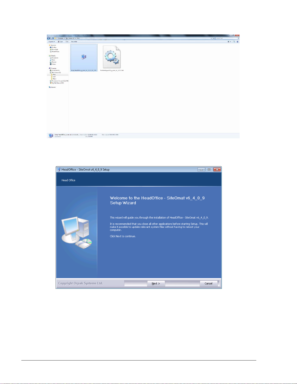
40
Figure 3-1. Installation File Icon
The following Welcome Screen appears (see Figure 3-2).
Figure 3-2. Head Office Setup Wizard Welcome Screen
Proceed as follows:
1. Click Next. The License Agreement screen appears (see Figure 3-3)
FMS and FHO User’s Manual - MDE-4821l
Page 43

41
Figure 3-3. License Agreement Screen
2. Select the I accept the terms of the License Agreement checkbox and click Next. The
Platform Support Library Welcome Screen appears (see Figure 3-4)
Figure 3-4. Platform Support Library Wizard Welcome Screen
3. Click Next. The following message appears (see Figure 3-5). Verify that the provided HASP
key is not plugged in, as required for installing the device driver and then click OK
FMS and FHO User’s Manual - MDE-4821
Page 44
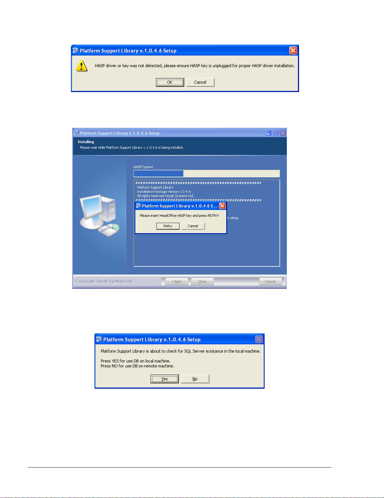
42
Figure 3-5. HASP Driver Installation Message
4. The installation process begins. The following message appears (see Figure 3-6)
Figure 3-6. HASP Insertion Message
5. Plug the provided HASP into a free USB port and then click Retry. The following message
appears (see Figure 3-7)
Figure 3-7. SQL Server Check Message
6. The Support Library checks for the presence of the software on the computer. Click Yes if
HO database is to be installed on the computer. The following message is displayed (see
Figure 3-8)
FMS and FHO User’s Manual - MDE-4821l
Page 45
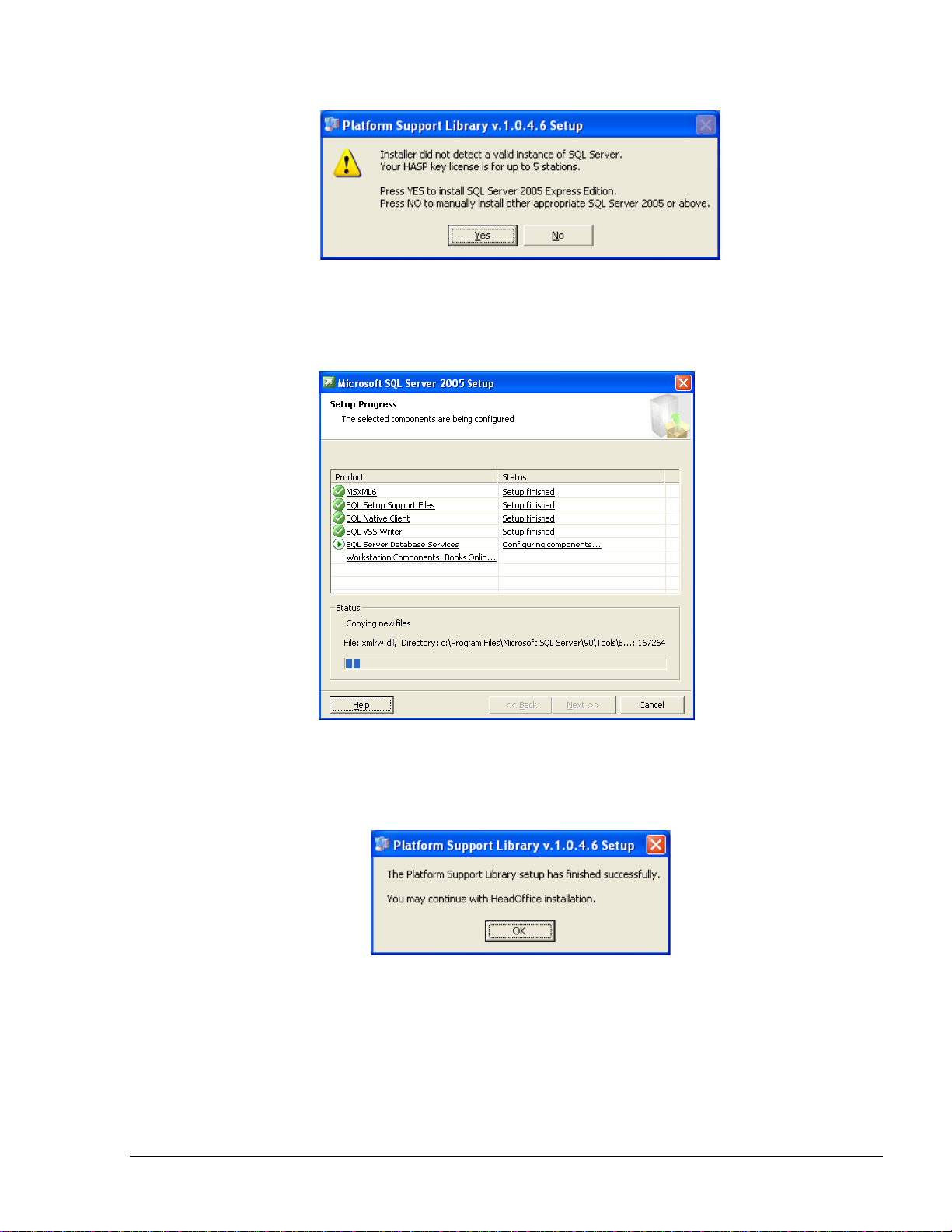
43
Figure 3-8. SQL Server Express Installation Message
7. Click Yes to proceed with SQL Server 2005 Express Edition installation. The SQL setup
progress screens appear (see Figure 3-9). Please wait until the process finishes
Figure 3-9. MS SQL Server Setup Progress Screen
8. At the end of the installation, the Platform Support Library Setup Completed Successfully
message appears (see Figure 3-10)
Figure 3-10. Platform Support Library Setup Completed Successfully Message
9. Click OK. The Choose Install Location screen appears (see Figure 3-11)
FMS and FHO User’s Manual - MDE-4821
Page 46

44
Figure 3-11. Choose Install Location Screen
10. Click Next to install the files in the default folder (C:\Orpak), or click Browse to select
another destination folder and then click Next. The following screen appears (see
Figure 3-12)
Figure 3-12. Select Installation Mode Screen – Express Install
FMS and FHO User’s Manual - MDE-4821l
Page 47

45
11. Select the Express install radio button and click Next. The installation process is fully
automated. The Installing screen displays process messages, as well as possible error
messages (see Figure 3-13)
Figure 3-13. Installing Screen – Express Installation
At the end of the installation, the Setup Completed Successfully message appears (see
Figure 3-14)
Figure 3-14. Setup Complete Message
FMS and FHO User’s Manual - MDE-4821
Page 48

46
12. Click OK and then click Close to exit the Wizard
NOTE
It is strongly recommended to restart the system a
few minutes after finishing the installation process.
FMS and FHO User’s Manual - MDE-4821l
Page 49
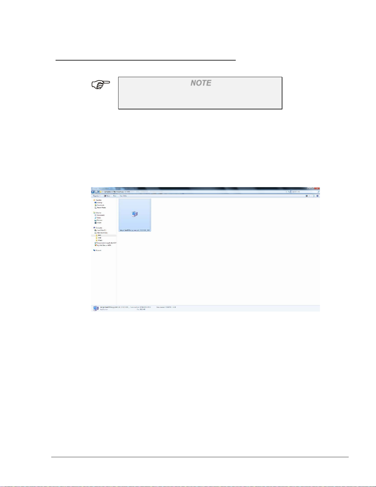
47
3.3. CUSTOM INSTALL – FULL LOCAL
The following describes the installation of both HO application and database on the same computer.
NOTE
Prior to installing HO, verify that MS SQL Server
2005 Standard Edition has been previously installed.
The installation file (HeadOffice_yy_mm_dd__X_X_X_XX__XXX.exe – with the correct date
and version number in the file name) is provided on a CD. After inserting the CD into the CD-ROM
drive, the installation process should start automatically.
If the installation does not start automatically, or the file was received from Orpak’s FTP site,
double-click on the executable installation file (see Figure 3-15).
Figure 3-15. Installation File Icon
The following Welcome Screen appears (see Figure 3-16).
FMS and FHO User’s Manual - MDE-4821
Page 50

48
Figure 3-16. Head Office Setup Wizard Welcome Screen
Proceed as follows:
1. Click Next. The License Agreement screen appears (see Figure 3-17)
Figure 3-17. License Agreement Screen
2. Select the I accept the terms of the License Agreement checkbox and click Next. The
Choose Install Location screen appears (see Figure 3-18)
FMS and FHO User’s Manual - MDE-4821l
Page 51

49
Figure 3-18. Choose Install Location Screen
3. Click Next to install the files in the default folder (C:\Orpak), or click Browse to select
another destination folder and then click Next. The following screen appears (see
Figure 3-19)
Figure 3-19. Select Installation Mode Screen – Custom Install
4. Select the Custom install radio button and click Next. The Installation Mode screen appears
(see Figure 3-20)
FMS and FHO User’s Manual - MDE-4821
Page 52

50
Figure 3-20. Installation Mode Screen
5. This screen allows selection of the installation mode and modification of port numbers
assigned to the HO services. To activate the fields on the screen, select the Custom Install
checkbox. Since Full Local installation is selected by default, click Next to continue. The
following message appears (see Figure 3-21)
Figure 3-21. HASP Insertion Message
6. Plug the provided HASP into a free USB port and then click Retry. The Configure Database
Parameters screen appears (see Figure 3-22)
FMS and FHO User’s Manual - MDE-4821l
Page 53

51
Figure 3-22. Configure Database Parameters Screen
7. Select the SQL Instance, enter SQL Server Username and Password and click Next
NOTE
Default SQL Passwords:
Sa123456 for servers running Windows 7
123456 for servers running Windows XP or 2000.
These passwords may be changed to meet the
organization's password policy.
Please consult your IT manager.
FMS and FHO User’s Manual - MDE-4821
Page 54

52
Figure 3-23. Choose Components Screen
8. The Choose Components screen appears (see Figure 3-23) allowing selection of the
components to be installed. Unless otherwise specified leave as is and click Install. The
installation process is fully automated. The Installing screen displays process messages, as
well as possible error messages (see Figure 3-24)
Figure 3-24. Installing Screen – Custom Install
FMS and FHO User’s Manual - MDE-4821l
Page 55

53
Since most of the errors are related to database access, verify that the database service is
running.
The Head Office is installed as a Windows Service; therefore it performs specific
functions, without requiring user intervention. At the end of the installation, the Setup
Completed Successfully message appears (see Figure 3-25)
Figure 3-25. Setup Complete Message
9. Click OK and then click Close to exit the Wizard
NOTE
It is strongly recommended to restart the system a
few minutes after finishing the installation process.
The installation of the HO installs the following files:
Under C:\Orpak\HeadOffice
• History.log – history of HO installation and upgrades
• Installation_HeadOffice_ yy_mm_dd__X_X_X_XX__XXX.log – log of the installation (its
name varies upon on the installed version)
• Uninstall.exe – HO uninstall program
• VERSION – contains the full version of the current installed HO
Under C:\Orpak\HeadOffice\bin
• HO_Serv_start.bat – starts all services at once
• HO_Serv_stop.bat – stops all services at once
• Under C:\Orpak\backup, all the automatic backup DB files are placed
FMS and FHO User’s Manual - MDE-4821
Page 56

54
3.4. CUSTOM INSTALL – FULL REMOTE
The following describes the installation of HO application on the local computer and the HO
database on a remote computer.
NOTE
Prior to installing HO, verify that MS SQL Server
2005 Standard Edition has been previously installed
on the remote computer.
Proceed as follows:
1. Perform steps 1 to 4 described above (refer to paragraph 3.3)
2. On the Installation Mode screen, select the Custom Install checkbox and then select the
Full Remote radio button (see Figure 3-26)
Figure 3-26. Installation Mode Screen – Selecting Full Remote Mode
3. Click Next. The following message appears (see Figure 3-27)
FMS and FHO User’s Manual - MDE-4821l
Page 57

55
Figure 3-27. HASP Insertion Message
4. Plug the provided HASP into a free USB port and then click Retry. The Configure Database
Parameters screen appears (see Figure 3-28)
Figure 3-28. Configure Database Parameters Screen –Full Remote Mode
5. Enter the remote computer IP address in the SQL Instance text box, enter SQL Server
Username and Password and click Next
NOTE
Default SQL Passwords:
Sa123456 for servers running Windows 7
123456 for servers running Windows XP or 2000.
These passwords may be changed to meet the
organization's password policy.
Please consult your IT manager.
6. Proceed with steps 8 and 9 as described in paragraph 3.3
FMS and FHO User’s Manual - MDE-4821
Page 58

56
3.5. CUSTOM INSTALL – HEAD OFFICE ONLY
The following describes the installation of HO application (without HO database) on the local
computer.
NOTE
Prior to installing HO, verify that MS SQL Server
2005 Standard Edition and HO database has been
previously installed on the computer.
When selecting this option, the only HO will be
installed, Database will not be modified.
Proceed as follows:
1. Perform steps 1 to 4 described in paragraph 3.3
2. On the Installation Mode screen, select the Custom Install checkbox and then select the
Head Office Only radio button (see Figure 3-29)
Figure 3-29. Installation Mode Screen – Selecting Head Office Only Mode
3. Click Next. The following message appears (see Figure 3-30)
FMS and FHO User’s Manual - MDE-4821l
Page 59

57
Figure 3-30. HASP Insertion Message
4. Plug the provided HASP into a free USB port and then click Retry. The Configure Database
Parameters screen appears (see Figure 3-31)
Figure 3-31. Configure Database Parameters Screen –Head Office Only Mode
5. Select the SQL Instance, enter SQL Server Username and Password and click Next
NOTE
HO database must be installed before installing HO
application. In cases where HO database is not
found, an error message is displayed (see
Figure 3-32). Abort the installation and restart after
HO database was installed.
FMS and FHO User’s Manual - MDE-4821
Page 60

58
Figure 3-32. HO Database Not Found Message
6. Proceed with steps 8 and 9 as described in paragraph 3.3
FMS and FHO User’s Manual - MDE-4821l
Page 61

59
3.6. CUSTOM INSTALL – DATABASE ONLY
The following describes the installation of HO database (without HO application) on the local
computer.
NOTE
Prior to installing HO database, verify that MS SQL
Server 2005 Standard Edition has been previously
installed on the remote computer.
Proceed as follows:
1. Perform steps 1 to 4 described in paragraph 3.3
2. On the Installation Mode screen, select the Custom Install checkbox and then select the
Database Only radio button (see Figure 3-33)
Figure 3-33. Installation Mode Screen – Selecting Database Only Mode
3. Click Next. The Configure Database Parameters screen appears (see Figure 3-34)
FMS and FHO User’s Manual - MDE-4821
Page 62

60
Figure 3-34. Configure Database Parameters Screen –Database Only Mode
4. Select the SQL Instance, enter SQL Server Username and Password and click Next
NOTE
Default SQL Passwords:
Sa123456 for servers running Windows 7
123456 for servers running Windows XP or 2000.
These passwords may be changed to meet the
organization's password policy.
Please consult your IT manager.
5. Proceed with steps 8 and 9 as described in paragraph 3.3
FMS and FHO User’s Manual - MDE-4821l
Page 63

61
3.7. UPGRADING HO
The following describes the upgrade of HO application to version 6.4.X.XX.
NOTE
It is highly recommended to backup HO database,
prior to upgrading HO application.
Proceed as follows:
1. Perform steps 1 to 2 described in paragraph 3.3. The following confirmation message
appears (see Figure 3-35)
Figure 3-35. Head Office Upgrade Confirmation Message
2. Click Yes. The Configure Database Parameters screen appears (see Figure 3-36) The
applicable fields are disabled since SQL Server parameters shouldn't be modified when
upgrading the application
Figure 3-36. Configure Database Parameters Screen – HO Upgrade
FMS and FHO User’s Manual - MDE-4821
Page 64

62
3. Click Next and proceed with steps 8 and 9 as described in paragraph 3.3
NOTE
In cases where the HO application was upgraded and
after the procedure is completed, it may be necessary
to delete the cookies from each client IE, in order for
the browser to reflect the changes.
FMS and FHO User’s Manual - MDE-4821l
Page 65

63
3.8. UNINSTALLING HO
The following describes the uninstallation of HO application.
NOTE
It is highly recommended to backup HO database,
prior to uninstalling HO from the computer.
Proceed as follows:
1. Double-click on the Uninstall executable file, located under Orpak\HeadOffice folder (see
Figure 3-37)
Figure 3-37. Orpak\HeadOffice Folder
2. The following confirmation message appears (see Figure 3-38)
Figure 3-38. Uninstalling HO Confirmation Message
3. Click Yes. The following Welcome Screen appears (see Figure 3-39)
FMS and FHO User’s Manual - MDE-4821
Page 66

64
Figure 3-39. Head Office Uninstall Wizard Welcome Screen
4. Click Next. The following screen appears, displaying the path of the folder which is to be
removed (see Figure 3-40)
Figure 3-40. Head Office Location Screen
5. Click Uninstall to start the uninstallation process. The following confirmation message
appears (see Figure 3-41)
FMS and FHO User’s Manual - MDE-4821l
Page 67

65
Figure 3-41. Database Tables Removal Confirmation Message
6. Click Yes to remove HO database tables, or click No to keep the tables on the computer.
The process is fully automated. The Uninstalling screen displays process messages, as well
as possible error messages (see Figure 3-42)
Figure 3-42. Uninstalling Screen
At the end of the installation, the Uninstallation Completed Successfully message is
displayed (see Figure 3-43)
FMS and FHO User’s Manual - MDE-4821
Page 68

66
Figure 3-43. Uninstallation Complete Message
7. Click Next. The following screen appears (see Figure 3-44)
Figure 3-44. Uninstallation Complete Screen
8. Click Finish to exit the Wizard.
FMS and FHO User’s Manual - MDE-4821l
Page 69

67
3.9. FAILURE TO RUN THE HO PROGRAM NOTE
Instructions for Advanced Users Only.
Possible causes of failure are:
1. No HASP protection key. Verify that the HASP is connected to the USB port
2. DotNet2.0 or Windows Installer 3.5 are not installed
3. The server Web port 443 is being used by another application. Verify that no other Web
server, such as IIS, is running. Some programs such as Skype may also use this port, and
cause failure. Port 443 must be available. In cases where it is occupied by other applications,
define another port for them
4. ODBC connection to database does not work. Go to the ODBC connection window ( select
Control Panel, Administrative Tools, Data Sources), as shown below (see Figure 3-45)
Proceed as follows:
Figure 3-45. ODBC Connection Dialog Screen
1. Select the system DSN tab
2. Select HO_DATA and click ‘Configure’. The following screen appears (see Figure 3-46)
FMS and FHO User’s Manual - MDE-4821
Page 70

68
NOTE
ODBC Microsoft SQL Server Setup is part of MS
Windows installation, therefore the procedure is not
described in this manual.
Figure 3-46. SQL Server DSN Configuration
3. If the user manages a small fleet using SQLEXPRESS software, make sure that the
definition in the ‘Server’ box is ‘.\SQLEXPRESS’
4. Click ‘Next’ and follow the instructions until the connection can be tested
5. Repeat the same procedure for HO_LANG and HO_META_DATA
6. In order to use a language other than English, change the language in the Head Office Setup
screen. If the change has been made but the correct fonts do not appear open SQL Studio
and run the following scripts in ‘C:\Orpak\HeadOffice\DB\mssql’: ‘LANG_drop.sql’
followed by ‘LANG.sql’ then ‘META_DATA_drop.sql’ followed by ‘META_DATA.sql
Database collation needs to be set to SQL_Latin1_General_CP1_CI_AS.
Only Username and Password are case sensitive.
FMS and FHO User’s Manual - MDE-4821l
Page 71

69
4.
Checkbox
An element permitting the user to enable/ disable
SECTION
0
4
COMMON FUNCTIONAL PRINCIPLES
4.1. GENERAL
This section explains generic principles, which the user should be familiar with, for proper
operation of the Administration, FMS and FHO applications and which will not be detailed in each
occurrence.
4.2. TERMINOLOGY
The FHO and FMS applications are user-friendly, window-based ap pl icat ions with a graphical
interface similar to other Windows applications. Common terms are used in this manual assuming
that their meaning is obvious, as depicted in Table 4-1.
Table 4-1. Common Terms (Examples from SiteOmat Application)
No. Name Appearance (Typical) Description
1. Cursor
2. Pointer
3. Text Box
5. Combo Box
6.
Radio
Buttons
7. Grid
|
An indicator pointing where text is to be inserted.
Points where the mouse is located on the screen.
An element allowing the user to input text
information.
a specific option.
An element allowing the user to choose one value
from a list. Clicking on the arrow-shaped button
in the combo box opens the list of values.
An element allowing the user to choose only one
of a predefined set of options.
A database consisting of column s (fields) and
rows (records). Grids are a common way of
displaying and handling data in the SiteOmat
application.
8. Scroll Bar
FMS and FHO User’s Manual - MDE-4821
A bar allowing continuous text to be viewed even
if it does not fit into the space in the window.
Clicking the ar row -shaped buttons in the ends
allows to move the body of the document.
Scroll bars may be either horizontal or vertical.
Page 72

70
Table 4-1. Common Terms (Examples from SiteOmat Application)
No. Name Appearance (Typical) Description
9. Tab
An element, usually located on the top of a
window, allowing the user to switch from
multiple documents located in a single window.
4.3. COMMON ACTIONS IN GRID
4.3.1. General
The user-interface of the applications is intuitive and requires little experience for using it. The
operative actions are common and generic across the various windows.
The Grids are displayed on most screens. All grids have paging options, enabling the user to go
forward and backward through the lists pages. A page contains up to 50 lines.
The common actions in a grid are as follows:
a. Navigating a grid
b. Selecting a row in a grid
c. Marking row(s) in a grid
d. Sorting a grid
4.3.2. Navigating a Grid
To navigate between pages in a grid, use the navigation bar at the left-hand side of the grid
(Figure 4-1). The user can move one page forward or backward, or go to first and last page (buttons
not applicable are grayed). The number in brackets displays current lines shown, out of total lines.
Figure 4-1. Grid Pages Selection Buttons
When in a page with a grid, you can perform the following:
• Click a grid column header to sort this page by this column
• Hold and drag the line separator between columns to change columns width
• Use the scroll bar to scroll lines and horizontal scroll bar to show more columns
Many buttons require selection of a grid row for operation. If not selected, an error message is
displayed (such as in the fleet grid), see Figure 4-2 below.
FMS and FHO User’s Manual - MDE-4821
Page 73

71
Figure 4-2. Grid Row Selection Message
4.3.3. Selecting a Row in a Grid
Selection of a row in a grid serves several purposes, such as for displaying the data associated with
grid. To select a row, click on the applicable row. Consequently, the row is highlighted in a blue
color (as seen in Figure 4-3), indicating that the row is currently selected.
Figure 4-3. Selecting a Row in a Grid
4.3.4. Marking Row(s) in a Grid
Marking a row, or multiple rows, in a grid is done prior to performing an action (e.g.: selecting
stations to a cluster), which affects the marked row(s). To mark a row, check the checkbox in the
left-hand side of the relevant row (see Figure 4-4).
Figure 4-4. Marking Grid Row(s)
4.3.5. Sorting a Grid
Sorting a grid is done simply by clicking on a column header (see Figure 4-5). The records are
consequently sorted by the selected column in an ascending order. Second click arranges the
records by descending order. The small triangle in the right-side of the selected header indicates the
current sorting order.
FMS and FHO User’s Manual - MDE-4821
Page 74
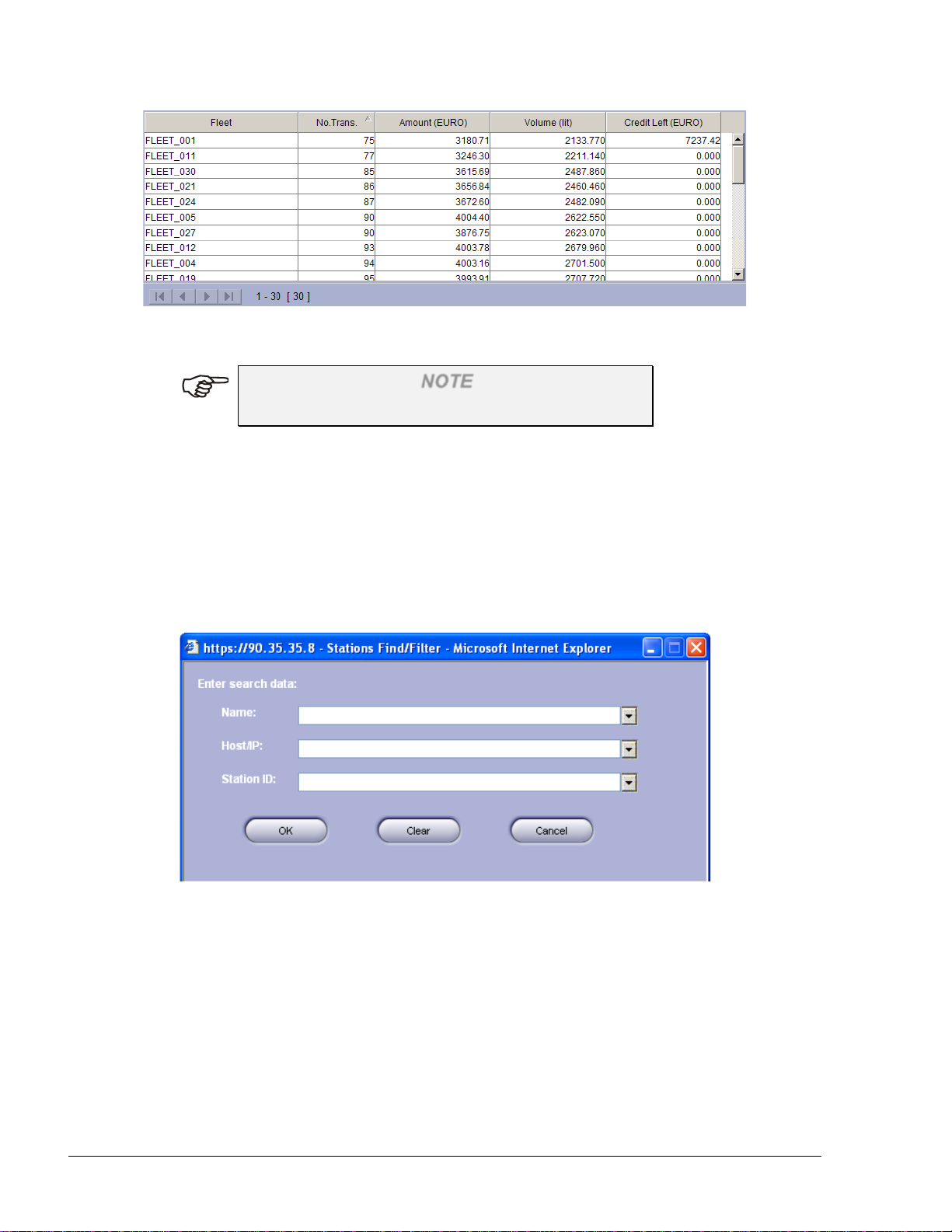
72
Figure 4-5. Sorting Grid Rows
NOTE
Sorting a grid unmarks all rows in grid.
4.3.6. Filtering a Grid
Many windows containing data grids provide an option to filter the grid according to search criteria,
thus showing only the entries that comply with the specified criteria. This option is especially
useful in cases where there are a large number of records.
There are two filtering options throughout the application:
1. Click on the Find/Filter button. The Stations Find/Filter window appears. Enter the search
criteria in the applicable text boxes (see Figure 4-6)
Figure 4-6. Stations Find/Filter Dialog Box
2. Select the search criteria from the drop down lists or the editable boxes in the headers,
multiple criteria may be selected (See Figure 4-7)
FMS and FHO User’s Manual - MDE-4821
Page 75

73
Figure 4-7 Filter Options in Grid Headers
4.4. NAVIGATION NOTES
4.4.1. General
The user-interface of the Administration, FMS and FHO applications may display common
messages during operation. These messages are common to several situations, and they are
provided below for general information.
NOTE
Do not use special characters (such as @#$%) in all
text fields throughout the applications.
4.4.2. Not Saving Change
If data has been changed in a dialog box or a screen and the user tries to navigate away from it
without saving the changes, the following message is displayed (see Figure 4-8):
Figure 4-8. Saving Changes Dialog Box
Click OK for approval, or Cancel for proceeding work in the same screen.
4.4.3. Filling All Fields
In many dialogue boxes, fields are mandatory and their captions are usually shown bold. If the user
tries to save data without filling these fields, the following message is displayed (see Figure 4-9):
FMS and FHO User’s Manual - MDE-4821
Page 76

74
Figure 4-9. Mandatory Fields Fill Requirement Dialog Box
Click OK for approval. The empty field is selected and in focus.
Proceed to complete the data.
4.4.4. Saving Data
When saving data or performing an operation, the following message appears (see Figure 4-10):
Figure 4-10. Processing Data Message
The dialog closes automatically when operation is performed (sometimes an additional message
Operation successful appears). If the operation seems to take too long (stuck), close the dialog by
clicking on the X button.
4.5. LOG FILES
4.5.1. General
The Administration, FMS and FHO applications include different Log files for debugging. These
can be enabled or disabled upon request.
4.5.2. Enabling Log File
Users can enable log files. Proceed as follows:
a. Click Admin in the menu bar
b. Click System Command menu
c. Click on the Enable logs button. Once this feature has been enabled, the Enable button
changes to Disable logs. The Debug.log function is always enabled.
Each log line starts with date and time format:
[2008-06-30 15:08:09.053 00011204]
FMS and FHO User’s Manual - MDE-4821
Page 77

75
The last number is the internal thread ID and can be used to track the flow of messages.
4.5.3. Logs Location
Logs are located in the following directory:
xx:\Orpak\HeadOffice\bin\log
4.5.4. Types of Log Files
There are several log files, differentiated by user's access level (ie administration_xxx .log,
fleetmanagment_xxx.log, etc.) and by the type of information they contain as follows:
• debug.log
This is the main application log. It shows the communication status with stations, errors due
to a failure to connect to a station.
Each time a station needs to be updated, it displays a message similar to:
Station updater: Time to update: {station name}
If an error occurs, the message displays
Station updater: Could not login into {station name} 192.168.1.5)
If the station is connected but data cannot be pushed or entered (similar to polling action), it
displays an error message:
Station updater: Failed push to station {station name}
(192.168.1.5)
During normal process of receiving data from stations, the following message shows how
much data was received and calculated:
Calculation process: Found 76 transactions
• DATA.log
Logs all SQL queries from the main database. It contains the user and stations data.
• LANG.log
Logs access to the LANG database. This log file gets language dependent string for display.
• META_DATA.log
Logs access to the META_DATA database. It provides fixed data as currency and other
measurements tables.
• WebAccess443.log
Logs all access to the web server (port 443). It includes error messages and status of
connections.
• WebComm443.log
Logs all web server traffic. It includes all HTML, scripts and XML files sent and received
from the browser. This Log file includes Web services requests.
FMS and FHO User’s Manual - MDE-4821
Page 78

76
SECTION
0
5
GETTING STARTED
5.1. GENERAL
This section provides initial instructions needed for the user to start using the FMS and FHO
Applications, namely launching the applications, login and familiarizing with the general
orientation of the application. This section provides references to the subsequent sections, which
discusses the different operative parts of the System.
NOTE
The FHO and FMS applications have been designed
and tested to run properly on Microsoft Internet
Explorer 7 and up. On any other browser (or
version), the application may not function properly.
5.2. FHO/FMS APPLICATION STARTUP
FHO and FMS Applications can be logged into using a standard browser from any PC. The
application is launched from the FHO computer and may be accessed from any networked
computer (directly connected to the FHO/FMS via the LAN) or from a remote computer with an
Internet browser over the Internet.
NOTE
In cases where the FHO server was upgraded and
after the procedure is completed, it may be necessary
to delete the cookies from each client IE, in order for
the browser to reflect the changes.
To access the application, launch the Internet browser and enter the address (IP address or domain
name) as follows:
https://192.168.1.104
(Each customer’s IP address may differ based on their network.)
IMPORTANT!!!
Before proceeding, go to Appendix A, and follow
the procedure. This enables the connection from a
web client to the FHO/FMS and improves browsing
capabilities
FMS and FHO User’s Manual - MDE-4821
Page 79

77
Once a link is established, the application login window is displayed.
The system grants access to authenticated users only. It sets its access level in accordance with the
organizational level of the user. The information regarding the login level of the user is provided in
the paragraph 5.3.
5.3. LOGIN
5.3.1. User and Password Identification
The FHO and FMS Applications incorporate powerful SSL mechanisms to allow only authorized
users to view and alter its contents. The application opens with a login dialog box, requesting the
username and password. The accessible contents and privileges of the user depend upon its access
level, as set in the User Management definitions of the Administration application (see
paragraph 6.8.1). The application is designed to grant each user with his suitable privileges and
block other capabilities, e.g., a station manager cannot view/modify stations other than his.
To access the Administration Application (as an administrator only), or the FMS Application (as
station manager for example) or the FHO Application (as fleet manager for example), enter the
correct User name and Password and click on the Login button as shown in Figure 5-1. The system
checks the entered information against the users listed in the system.
Figure 5-1. Login Dialog Box for Accessing the Applications
NOTE
Default username is Admin and default password is
Admin. It is highly recommended to change these
parameters to meet the customer's security needs.
If the user and the password are authenticated, the user logs into either Administration Application
or FHO/FMS Applications with its applicable access level.
NOTE
Disable any sort of pop-up blockers, because it
interferes with the operation of the application.
FMS and FHO User’s Manual - MDE-4821
Page 80

78
Otherwise, the following message is displayed (see Figure 5-2):
Figure 5-2. Bad User or Password Message
• You may click on the ‘Login/Pass’ button (see Figure 5-3) to enter the system and
immediately obtain a dialog to change the password:
Figure 5-3. Password Change Screen
• Enter the selection in the New Password and Confirm Password field boxes
A Password must have at least six characters. Otherwise, the following request message appears
(see Figure 5-4).
Figure 5-4. Password Minimum Characters Message
Also, both passwords field boxes must match. Otherwise, the following request message appears
(see Figure 5-5).
FMS and FHO User’s Manual - MDE-4821
Page 81

79
Figure 5-5. Password Do not Match Message
• Once the Password and Confirmation have been typed correctly, click OK to save the new
password
If the user clicks Cancel, the dialog closes, password change is not made and the user is not logged
into the system.
FMS and FHO User’s Manual - MDE-4821
Page 82

80
SECTION
0
6
OPERATING AS ADMINISTRATOR
6.1. GENERAL
This section provides instructions for operating at a higher level in the management hierarchy, as
defined in the Head Office Administration system: for operating as an administrator only.
NOTE
The windows and actions described in this section
are only accessible to Administrators.
6.2. ADMINISTRATOR APPLICATION START SCREEN
After successful login, the Administrator Application screen appears (see Figure 6-1).
This screen includes two sections:
a. Navigation Bar for the Administration Application (located on the left side of the screen)
b. Application Icon per each FHO application that the company has purchased (located on the
center of screen). Clicking on each icon opens the relevant application.
FMS and FHO User’s Manual - MDE-4821
Figure 6-1. Administration Application Opening Screen
Page 83

81
Element
Description
Presents the main screen with all FHO application buttons.
Connects the SiteOmat Station Controllers situated in each gas station to
Sets up and customizes the application (interface language,
Enables viewing system warnings and logins.
Sets the operating mode of the Administrator, defines users' level of
Opens a PDF file of Help documentation on a separate window.
Closes the current window and opens the login dialog - in order to exit
6.3. NAVIGATING THROUGH THE ADMINISTRATION APPLICATION
Accessing the various capabilities of the Administration Application is done using the Navigation
Bar on the left-hand side of the window. The Navigation Bar appears throughout the
Administration application, and contains buttons, which lead to the various windows of the
application, within the boundaries of the user’s access level. Those buttons and screens allow the
administrator to define and change parameters relevant to all FHO applications. The objective of
each button in the Navigation Bar is depicted as follows (see Table 6-1):
Table 6-1. Navigation Bar Buttons
the HO System, and bundles the stations into clusters.
measurements, formats, etc.)
authentication, and accordingly the level of access rights to define
stations and data display.
the Administration Application.
6.4. SETUP SECTION
The following paragraphs provide instructions for setting up the Administration Application (e.g.:
setting the interface language, setting the measurement units and more), describe the user
management and group management features, and provide instructions for setting backup
parameters.
The setup of the Administration Application is the next stage after the physical installation and
power-up of the unit at the installation site. The Setup section in the application, available only to
Administrator users, is accessed by clicking on the Setup navigation button, and consists of the
following subsections:
• General– includes general setup parameters.
• Reports – sets report headers and company logo.
• Formats Setup – serves for specifying the favorable measurement units and format of data types
presented in the application (e.g.: in the reports).
FMS and FHO User’s Manual - MDE-4821
Page 84

82
• Alarms – serves for displaying alarm summary reports. The user can define alarms priority and
audio and perform several actions such as alarm acknowledgements.
• Products – defines the products that the company is providing.
• FMS – defines the setup parameters relevant to FMS screens.
• Card-Format – allows definition of new refueling authorization card formats.
6.4.1. General Tab
To enter the General Setup window (see Figure 6-2), click the on the Setup navigation button, or
select the General tab if already in the Setup section.
Figure 6-2. Setup Screen – General Tab
In the General tab the administrator can define the following settings (see Table 6-2):
FMS and FHO User’s Manual - MDE-4821
Page 85

83
Section
Description
Company Data
Enables the administrator to enter the following company information:
Tag Acqui r i ng
Defines the communication channel to the MiFare reader/ Fleet Head
Year first day for
Sets the day of the year on which the Year Limit begins (default:
Language
Enables the administrator to select the interface and reports language,
Fleet Management
Enables users to configure the automatic devices and entities import
Mail configuration
The Properties button opens a dialog box in which the administrator
Support OrData
Configures the system to interface with DataPass PLUS devices which
Update stations
Enables the creation of devices without card number field. The card
Card number
Enables creating devices without needing to fill up the Card number
Upload
Defines the transaction upload method, to match the company's billing
Clock
Enables users to synchronize all stations clocks based on FHO server
Table 6-2. General Tab Fields
Name, Address, Phone, Email, Contact Person and Owner Name. The
Company name appears in report headers
Device
limits rule
Import
Systems
with not burned
devices
Office Pod in order to acquire tags
January 1st)
using the drop down list. To update all screens with the new language,
click on Save, log out the system and login again
process, see section 6.4.2.
can view and change mail configurations: Host IP, Port, User,
Password, filling the corresponding text boxes
collects On-Board Diagnostics error codes and additional vehicle
parameters (See paragraph 8.6.2.3). This feature is available in version
6.3.2 or later
number can be added later manually or automatically by selecting the
next checkbox (Card number automatically generated).
automatically
generated
field.
The vehicle is identified by its plate, fleet code and the organization ID
and automatically receives its Card number after the first fueling.
Transaction Policy
policies and facilitate reconciliation.
• Select the All radio button to upload all transactions, including
cash, credit cards, local accounts, attendant or auto authorize
transactions (Default)
Select Transactions authorized by HO to upload transaction
performed with devices defined in FHO only
synchronization
clock. The clock synchronization mechanism supports different time
zones as follows:
FMS and FHO User’s Manual - MDE-4821
Page 86

84
• The HO sends the time based on GMT time zone
Credit Info
Sets the frequency/time limit for storing online authorization holds.
• SiteOmat receives the time and modifies it according to the
local time zone as previously set in SiteOmat OrCU
Administration Screen or Setup Wizard (see SiteOmat Setup
and Maintenance Manual P/N 817423756 paragraphs 3-5. and
4-3.2 respectively)
Select the time for executing daily synchronization utilizing the dropdown lists.
Cleaning Settings
FHO preauthorizes the fleet for a specific amount, holding this balance
as unavailable until settlement. Since the preauthorized amount could
differ from the transaction amount, or the transaction could be
cancelled the system renders the balance available again in order to
keep the fleet credit accurately updated
6.4.2. Fleet Management Import
Devices and all related entities (Model, Rule, Group Rule, Fleet and Department) can be imported
in one or separate files to the FHO system from the customer ERP. The Fleet Management Import
option enables users to schedule an automatic daily import process.
Devices and entities import can be also done manually, by clicking on the Import button on the
respective Fleet Management screen (see Section 7).
To set the automatic process, proceed as follows:
1. Click on the Setup button in the Fleet Management Import section on the Setup Screen
shown above
2. The Fleet Management Import Scheduler dialog box appears (see Figure 6-3)
3. Leave the Enable automatic Fleet Management import checkbox selected
Figure 6-3. Fleet Management Import Scheduler Dialog Box
4. Select the time of import, utilizing the Time of day for import (hh:mm) drop-down lists
FMS and FHO User’s Manual - MDE-4821
Page 87

85
5. Enter the source folder into the Import Folder textbox
6. Click on Save to save the changes and close the dialog box, or Cancel to close the dialog
box without saving the changes
NOTE
The file format should be Microsoft Office Excel
ASCII Comma Separated Values (CSV).For further
information on the import file format and fields
please refer to APPENDIX B.
6.4.3. Reports Tab
The Reports screen enables the user to define report headers and company logo. To open this screen
(see Figure 6-4), click the on the Setup navigation button and select the Reports tab.
Figure 6-4. Setup Screen – Reports Tab
To create a header, proceed as follows:
1. Enter text for the report header in the Extra Text text boxes
2. Click Load to select an image file to be used as the company logo
FMS and FHO User’s Manual - MDE-4821
Page 88

86
3. Click Save to save any changes made to this tab before navigating away
NOTE
After changing an existing logo in FHO server, it
may be necessary to delete the cookies from each
client Internet Explorer, in order for the browser to
reflect the changes.
Clicking on the Environment Report Header button opens the Environmental Header Titles
dialog box (see Figure 6-5) that contains several text boxes for titles and subtitles edition. The
changes are saved by clicking on the Save button.
Figure 6-5. Environment Report Header Dialog Box
Clicking on the Vapor Recovery Throughput Form button opens a dialog box (see Figure 6-6)
that contains text boxes for editing the details of the local environmental authority to which the
form is submitted. The changes are saved by clicking on the OK button.
Figure 6-6. Vapor Recovery Throughput Form Setup Dialog Box
FMS and FHO User’s Manual - MDE-4821
Page 89

87
6.4.4. Formats Tab
Use the Formats tab to define all measurement units used throughout the Head Office screens and
reports. Consumption measurement units affect the calculation of consumption.
To open the Formats screen (see Figure 6-7), click on the Setup navigation button and select the
Formats tab.
Figure 6-7. Setup Screen – Formats Tab
Click Save before navigating away from this tab to save the changes.
The measurements parameters to be used in screens and reports are as follows (see Table 6-3):
FMS and FHO User’s Manual - MDE-4821
Page 90

88
Parameter
Description
Volume
Volume measurement (default: gallons).
Distance
Distance measurement (default: miles).
Currency
Currency in use (default: US dollars).
VAT
Value Added Tax (VAT) percentage (default: 0%).
Odometer
Distance per fuel consumption measurement (default: miles per
Density
Fuel density at a certain temperature (Default: lb/ft³).
Height
Measurement of tank height level (Default: inches).
Temperature
Temperature Display inside the fuel tank (Default ºF).
EH Consumption
Time per fuel consumption measurement (default: hours per gallon).
Flow Rate
Volume of fuel which passes per unit time (default: gallons per hour).
Height (display)
Height of the tank displayed on screens and reports (Default: inches).
Display
Description
Date
The date format used in the application (default: DD/MM/YY).
Time
The time format used in the application (default: HH:MM:SS).
Thousand
The thousand separator used in the application (default: comma).
Decimal Notation
The decimal notation used in the application (default: dot).
Volume display
The volume format used in the application (default: xxxxx.xx).
Currency display
The volume format used in the application (default: xxxxx.xx).
PPV display
The Price Per Volume format used in the application (xxxxx.xxx).
Table 6-3. Measurement Parameters
Consumption
gallon).
(measurement)
The display formats to be used in screens, receipts and reports are as follows (see Table 6-4):
Table 6-4. Display Formats
Separator:
FMS and FHO User’s Manual - MDE-4821
Page 91

89
6.4.5. Alarms Tab
To open the Alarms screen, select the Alarm tab (see Figure 6-8).
The Alarms Management screen enables users to define the alarm attributes. The types of alarms
are predetermined in the system, and they are listed in the Alarm Code column by ascending
number. The administrator can only change their attributes.
To change an alarm attributes, first select the alarm by clicking on the corresponding row. The
selected alarm attributes are shown in the selection boxes (along with its name in the left box). Set
the attributes from the drop-down lists:
• Priority: Select from Journal to Urgent (5 selections)
• Enable: Yes or No (to Disable an alarm)
• Audio: Select from No Audio to Attention (6 selections)
Click Update to apply the selections. Verify that the new attributes are displayed on the alarm's
corresponding row.
Figure 6-8. Setup Screen – Alarms Tab
FMS and FHO User’s Manual - MDE-4821
Page 92

90
6.4.6. Products Tab
This paragraph provides instructions for defining the various products (may be petrol products or
lubricants), which exist in the gas stations connected to the system and consequently may appear in
the FHO and FMS reports.
To open the Products main window, select the Products tab (see Figure 6-9).
It is important to define the products, as much as
possible, before connecting the gas station to the
system. If a new product is added after the stations
are connected, map the product in the relevant
station (refer to 6.5.2.5).
If connected to stations that have blended products
(composed of two base products stored in two
different tanks), define the mixed product, for FMS
will include the blended products in the relevant
reports
Figure 6-9. Setup Screen – Products Tab
NOTE
FMS and FHO User’s Manual - MDE-4821
Page 93

91
Display
Description
Product Name
Name identifying the product in all system screens and reports
Short Name
Abbreviation identifying the product in all system screens and reports
Product Code
Code identifying the product in all system screens and reports
Product VR Code
Product code for the Vapor Recovery Throughput Reporting Form, see
Product Type
Product type: Wet, Dry, Lubricants, Services, Fees. Selected using
Color
Color representing the product in graphic reports. To select the color,
6.4.6.1. Creating a New Product
To define a new product, proceed as follows:
1. Click on the New button in the Products main window
2. The Products screen appears (see Figure 6-10)
3. Fill the applicable fields (see Table 6-5)
Figure 6-10. New Product Dialog Box
Table 6-5. Products Dialog Box Fields
paragraph 12.2.3.6
the drop-down list
click on the color square to open a pop up color palette
4. Click OK to save changes and close the window.
FMS and FHO User’s Manual - MDE-4821
Page 94

92
6.4.6.2. Product Properties
To modify products properties, proceed as follows:
1. Select a product by clicking on the corresponding row
2. Click Properties
3. The Product screen appears
4. Enter the changes in the respective text boxes
5. Click OK
6.4.6.3. Deleting a Product
To delete an existing product from the FHO/FMS database, proceed as follows:
1. Double-click a row for selecting the product to be deleted
2. Click on the Delete button
3. A confirmation message is displayed to prevent accidental deletion.
4. Click OK.
NOTE
A Product may not be deleted if a product in a
station is mapped to it (see paragraph 6.5.2.5, see
Figure 6-22).
Figure 6-11. Cannot Delete Product Message
FMS and FHO User’s Manual - MDE-4821
Page 95
93
6.4.7. Price Lists
6.4.7.1. General
Fleets, departments and devices can be associated to a particular price list. Price lists are derived
from the base price defined for each product.
While refueling and after identification, the driver sees the specific price linked to the device on the
dispenser (on dispensers supporting price display). The price changes back to base price right after
the transaction is completed and the nozzle is placed back on the dispenser.
NOTE
Price lists can only be associated to hand held
vehicle devices.
If a driver lifts the nozzle first and then presents the
card/tag/key, he's notified and the process is stopped.
The transaction is not authorized in the following cases:
a. A device linked to a price list is recognized, but the pump price update has failed
b. A driver using a device linked to a price doesn't return the nozzle back to dispenser,
and consequently the system doesn't update the pump back to the base price
6.4.7.2. Setup
Departments and devices automatically inherit the fleet's price list; the association may still be
overridden by assigning departments or devices different price lists or none.
To define special discount lists, click on the Price Lists button. The Wet Price Lists dialog box
appears (see Figure 6-12)
FMS and FHO User’s Manual - MDE-4821
Page 96
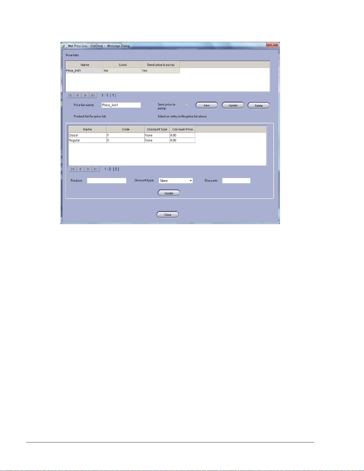
94
Figure 6-12. Wet Price Lists Dialog Box
The dialog box contains two grids:
a. The upper grid contains all price list defined.
b. The lower grid displays all products previously set in the system
To create a new price list, proceed as follows:
1. Enter a name in the Price list name text box
2. Select the Send price to pump checkbox in cases where the special price is sent to
the pump. Otherwise, the base price remains in the transaction, and the controller
calculates the price after discount
3. Click on the New button. The new list appears in the Price lists grid
4. Select the desired product in the products grid by clicking on its row
5. Select the Discount type to be applied, utilizing the drop-down list:
• Fixed: to set a fixed price
• Absolute to reduce a specific amount,
• Percentage to reduce a percentage of the base price,
• or None to leave the price as is
6. Enter the amount or percentage in the Discount text box
FMS and FHO User’s Manual - MDE-4821
Page 97

95
7. Click on the Update button to apply the changes
To Update an existing price list, select the required list from the Price list grid by clicking on it and
proceed as described from step 3 onwards.
To delete a price list, select the required list from the Price list grid by clicking on it and click on
the Delete button.
Click Close to close the dialog box and return to the Products screen.
After a price list is defined, devices can be associated to it from the Information tab on the
Fleet/Department/Device Properties dialog boxes (see paragraphs 7.8.4, 7.9.4 and 7.10.1.2
respectively).
6.4.8. FMS Screen
The FMS screen enables users to define parameters relevant to the different FMS screens (Order
form, status screen, etc.)
To open the FMS screen (see Figure 6-13), select the FMS tab.
Figure 6-13. FMS Screen
FMS and FHO User’s Manual - MDE-4821
Page 98

96
6.4.8.1. Level Status
This section enables users to define tank status warning levels depending on days left to sell, and
select colors associated with the defined fuel level warnings and alarms.
Set up the warning levels as follows:
1. For 1-2 days left to sell: select '1' in Level 1 combo box. Assign a red color for this
indication (or a different color) by clicking on the rectangular box associated with Level
1. Select a color from the popup color selection table
2. For 3-5 days left to sell: select '4' in Level 2 combo box and assign an orange color (or a
different color) for level 2 indication as described above
3. For 6-9 days left to sell: select '9' in Level 3 combo box and assign a yellow color (or a
different color) for level 3 indication as described above
In addition, assign a color for alarms in the system as described above.
Click Save to save the changes.
6.4.8.2. Flow Rate Interval
Flow Rate checks the average flow from each tank. This feature helps the administrator to avoid the
possibility of fraud.
Select the time interval values for flow rate checks, utilizing the drop-down list (1 up to 60 minutes)
and click Save to apply the changes.
6.4.8.3. Historical Volume Averages for Tanks Calculation
Clicking on the Calculate button calculates volume averages for all tanks, essential for the expected
days forecast included in the Daily Inventory by Fuel Type FMS report (see paragraph 12.2.2.4).
This feature enables users to generate the report based on existing data base
The data is processed by the system and at completion, a successful operation message appears.
Click OK to close the message.
6.4.8.4. Fuel Order and Delivery
This section enables to delineate fuel orders and set warning parameters for differences found on
fuel deliveries or reports (see Table 6-6).
FMS and FHO User’s Manual - MDE-4821
Page 99

97
Element
Description
Order form text
Enables users to enter header text lines to accompany the produced
Invoice diff
Enables users to determine the maximum acceptable percentage of
Report diff
Enables users to determine the maximum acceptable percentage of
Manual delivery
Check the box in cases when the user manually measures the fuel
Table 6-6. Fuel Order & Delivery Elements
lines 1, 2 & 3
percentage
orders.
deviation of fuel delivered from the invoice data. A higher percentage
generates an alarm.
percentage
deviation of fuel delivered from the invoice data in Invoice VS. Order
report.
input fields check
box
levels using a dip stick before and after the delivery; uncheck the box
in cases when manual delivery measurement is done only after the
delivery.
Click Save to save the changes.
6.4.8.5. Depot and Supplier Setup
This section enables users to view or modify the Depot and Supplier lists.
Depots are sorted by names.
The supplier list includes the following details:
• Name
• Contact Person
• Plate Number (vehicle number)
• Email
• Fax
Click Add to create a new item in the corresponding list, double click on the next available line to
place the cursor for entering the Depot Name. Click delete to eliminate an existing item from the
lists and click Save to save the changes.
6.4.8.6. Deliveries Screen Sel ect ion
Deliveries Screen Selection enables customers who manage Deliveries but not Orders to configure
the system for deliveries management only. (see paragraph 10.5).
Default setting is Orders and Deliveries (unselected). To change the setting, select the Deliveries
Screen Selection checkbox click on the Save button
The data is processed by the system and at completion, a successful operation message appears.
Click OK to close the message.
FMS and FHO User’s Manual - MDE-4821
Page 100

98
6.4.9. Card-Format
This screen allows professional technicians to customize and insert new refueling authorization card
formats into the system by defining the card layout attributes.
To open the Card-Format screen (see Figure 6-14), select the Card-Format tab.
Figure 6-14. Card Format Screen
6.4.9.1. Defining a New Card Format
To define a new card format, proceed as follows:
1. Click on the New button
2. The Data Format dialog box appears (see Figure 6-15)
FMS and FHO User’s Manual - MDE-4821
 Loading...