

Page 1

Introduction
Purpose
This manual provides instructions for installing a Server and additional hardware components
in the Islander
connected to the T-Chek
Table of Contents
Topic Page
Introduction
Important Safety Information
Installing the FiPay Server and Additional Hardware Components in the 8-hose
Islander PLUS System
MDE-5045
FiPay™ Server Retrofit Kit for 8-hose Islander
Installation Guide
January 2013
™
PLUS system using the FiPay™ application. This Islander PLUS system is
™
network for card verification
1
4
6
Required Tools
Following tools are required for installing the FiPay Server and additional hardware
components in the Islander PLUS system:
Parts List
Following table lists the parts included in the M13062K001 Kit for installing the FiPay Server
and additional hardware components in the Islander PLUS system.
Item Description Part Number Quantity
1 5-port Switch M09680B032 1
2 Wiring Harness with Fuse M09680B036 1
3 3-feet Ethernet
4 FiPay Network Server PA0414000 1
5 Server Bracket M13062A001 1
6 Wire Clips Q13558-04 4
7 M4 X 16 Phillips Head Screws Q12845-60 2
8 FiPay Server Retrofit Kit for 8-hose Islander Installation Guide MDE-5045 1
• Islander PLUS for 8-hose Mechanical Pumps (PA093400801)
• Wire Stripers/Cutters
• Electrical T ape
• # 2 Phillips
®
Head Screwdriver with 8-10-inch Blade
• 9/32-inch Nut Driver
®
Patch Cable Q13850-03 3
MDE-5045 FiPay™ Server Retrofit Kit for 8-hose Islander Installation Guide · January 2013 Page 1
Page 2
Introduction
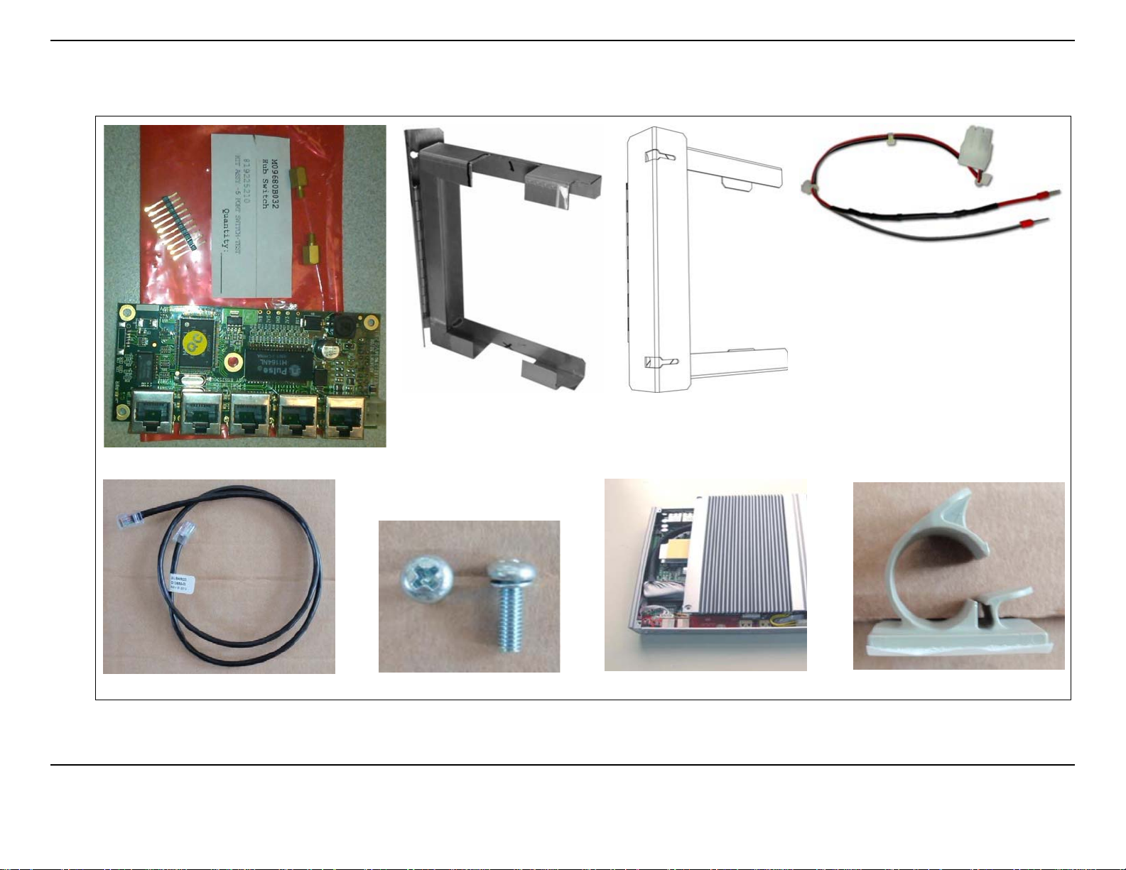
Figure 1: M13062K001 Kit Parts
Cable Assembly with Fuse Built-in (M09680B036)
5-port Switch (M09680B032)
3-feet Ethernet Patch Cable (Q13850-03)
Server Bracket
(M13062A001- Front View)
M4 X 16 Screws (Q12845-60)
FiPay Network Server (PA0414000)
Server Bracket
(M13062A001- Rear View)
Wire Clips (Q13558-04)
Page 2 MDE-5045 FiPay™ Server Retrofit Kit for 8-hose Islander Installation Guide · January 2013
Page 3

Related Documents
Document
Number Title GOLD Library
®
MDE-4255 Gasboy
MDE-4811 Islander PLUS and ICR PLUS Installation Manual Gasboy Fleet PLUS System
MDE-4813 CFN
MDE-4817 SiteOmat In-House Station Controller Setup and
Maintenance Ma
MDE-4818 SiteOmat In House Station Controller Users Manual Gasboy Fleet PLUS System
Warranty Policy St atement for USA and Canada • Gasboy Safety and Warranty Docs
®
PLUS Installation Manual Gasboy Fleet PLUS System
Abbreviations and Acronyms
Term Description
LAN Local Area Network
™
OrCU Orpak
PCB Printed Circuit Board
SSL Secure Socket Layer
WAN Wide Area Network
Controller Unit
Introduction
• Gasboy Policy Documents
Gasboy Fleet PLUS System
nual
Warranty
For information on warranty , refer to MDE-4255 Gasboy Warranty Policy Statement for USA
and Canada. If you have any warranty-related questions, contact Gasboy’s Warranty
Department at its Greensboro location.
MDE-5045 FiPay™ Server Retrofit Kit for 8-hose Islander Installation Guide · January 2013 Page 3
Page 4
Important Safety Information
Important Safety Information
Notes: 1) Save this Important Safety Information section
in a readily accessible location.
2) Although DEF is non-flammable, Diesel is
flammable. Therefore, for DEF cabinets that are
attached to Diesel dispensers, follow all the
notes in this section that pertain to flammabl e
fuels.
This section introduces the hazards and safety precautions
associated with installing, inspecting, maintaining or servicing
this product. Before performing any task on this product, read
this safety information and the applicable sections in this
manual, where additional hazards and safety precautions for
your task will be found. Fire, explosion, electrical shock or
pressure release could occur and ca use death or seriou s injury,
if these safe service procedures are not followed.
Preliminary Precautions
You are working in a potentially dangerous environment of
flammable fuels, vapors, and high voltage or pressures. Only
trained or authorized individuals knowledgeable in the related
procedures should install, inspect, maintain or se rvice this
equipment.
Emergency To tal Electrical Shut-Off
The first and most important information you must know is how
to stop all fuel flow to the pump/dispenser and island. Locate
the switch or circuit breakers that shut off all power to all fueling
equipment, dispensing devices, and Submerged Turbine
Pumps (STPs).
!
WARNING
!
Total Electrical Shut-Off Before Access
Any procedure that requires access to electrical components or
the electronics of the dispenser requires total electrical shut off
of that unit. Understand the function and location of this switch
or circuit breaker before inspecting, installing, maintaining, or
servicing Gasboy equipment.
Evacuating, Barricading and Shuttin g Off
Any procedure that requires access to the pump/dispenser or
STPs requires the following actions:
The EMERGENCY STOP, ALL STOP, and
PUMP STOP buttons at the cashier’s station
WILL NOT shut off electrical power to the
pump/dispenser. This means that even if you
activate these stops, fuel may continue to flow
uncontrolled.
You must use the TOTAL ELECTRICAL
SHUT-OFF in the case of an emerge ncy and not
the console’s ALL STOP and PUMP STOP or
similar keys.
Read the Manual
Read, understand and follow this manual and any other labels
or related materials supplied with this equipment. If you do not
understand a procedure, call a Gasboy Authorized Service
Contractor or call the Gasboy Service Center at
1-800-444-5529. It is imperative to your safety and the safety of
others to understand the procedures before beginning work.
Follow the Regulations
Applicable information is available in National Fire Protection
Association (NFPA) 30A; Code for Motor Fuel Dispensing
Facilities and Repair Garages, NFPA 70; National Electrical
Code (NEC), Occupational Safety and Health Administration
(OSHA) regulations and federal, state, and local codes. All
these regulations must be followed. F ailure to install, inspect,
maintain or service this equipment in accordance with these
codes, regulations and standards may lead to legal citations
with penalties or affect the safe use and operation of the
equipment.
Replacement Parts
Use only genuine Gasboy replacement p art s and retrofit ki ts on
your pump/dispenser. Using parts other than genuine Gasboy
replacement parts could create a safety hazard and violate
local regulations.
Safety Symbols and Warning Words
This section provides important information about warning
symbols and boxes.
Alert Symbol
This safety alert symbol is used in this manual and on
warning labels to alert you to a precaution which must be
followed to prevent potential personal safety hazards. Obey
safety directives that follow this symbol to avoid possible injury
or death.
Signal Words
These signal words used in this manual and on warning labels
tell you the seriousness of particular safety hazards. The
precautions below must be followed to prevent death, injury or
damage to the equipment:
DANGER: Alerts you to a hazard or unsafe practice
!
which will result in death or serious injury.
WARNING: Alerts you to a hazard or unsafe practice
!
that could result in death or serious injury.
CAUTION with Alert symbol: Designates a hazard or
!
unsafe practice which may result in minor injury.
CAUTION without Alert symbol: Designates a hazard
or unsafe practice which may result in property or
equipment damage.
Working With Fuels and Electrical Energy
Prevent Explosions and Fires
• An evacuation of all unauthorized persons and vehicles
from the work area
• Use of safety tape, cones or barrica des at the affected
unit(s)
• A total electrical shut-off of the affected unit(s)
Fuels and their vapors will explode or burn, if ignited. Spilled or
leaking fuels cause vapors. Even filling customer tan ks will
cause potentially dangerous vapors in the vicinity of the
dispenser or island.
DEF is non-flammable. Therefore, explosion and fire safety
warnings do not apply to DEF lines.
Page 4 MDE-5045 FiPay™ Server Retrofit Kit for 8-hose Islander Installation Guide · January 2013
Page 5
Important Safety Information
No Open Fire
In an Emergency
Inform Emergency Personnel
Compile the following information and inform emergency
Open flames from matches, lighters, welding torches
or other sources can ignite fuels and their vapors.
No Sparks - No Smoking
personnel:
• Location of accident (for example, address, front/back of
building, and so on)
• Nature of accident (for example, possible heart attack, run
over by car, burns, and so on)
Sparks from starting vehicles, starting or using power tools,
burning cigarettes, cigars or pipes can also ignite fuels and their
vapors. Static electricity, including an electrostatic charge on
your body, can cause a spark sufficient to ignite fuel vapors.
Every time you get out of a vehicle, touch the metal of your
vehicle, to discharge any electrostatic charge before you
approach the dispenser island.
• Age of victim (for example, baby, teenager, middle-age,
elderly)
• Whether or not victim has received first aid (for example,
stopped bleeding by pressure, and so on)
• Whether or not a victim has vomited (for example, if
swallowed or inhaled something, and so on)
!
WARNING
Gasoline/DEF ingested may cause
Working Alone
It is highly recommended that someone who is capable of
rendering first aid be present during servicing. Familiarize
yourself with Cardiopulmonary Resuscit atio n (CPR) me thods, if
unconsciousness and burns to internal organs.
Do not induce vomiting. Keep airway open.
Oxygen may be needed at scene. Seek medical
advice immediately.
you work with or around high voltages. This information is
available from the American Red Cross. Always advise the
station personnel about where you will be working, and caution
them not to activate power while you are working on the
equipment. Use the OSHA Lockout/Tagout procedures. If you
are not familiar with this requirement, refer to this information in
the service manual and OSHA documentation.
Working With Electricity Safely
Ensure that you use safe and established practices in working
with electrical devices. Poorly wired devices may ca us e a fire,
explosion or electrical shock. Ensur e th at grounding
connections are properly made. Take care that sealing devices
and compounds are in place. Ensure that you do not pinch
!
WARNING
DEF generates ammonia gas at higher temperatures.
When opening enclosed panels, allow the unit to air out to
avoid breathing vapors.
If respiratory difficulties develop, move victim away from
source of exposure and into fresh air. If symptoms persist,
seek medical attention.
WARNING
!
Gasoline inhaled may cause unconsciousness
and burns to lips, mouth and lungs. Keep airway
WARNING
!
open. Seek medical advice immediately.
wires when replacing covers. Follow OSH A Loc kout/Ta gout
requirements. Station employees and service contractors need
to understand and comply with this program completely to
ensure safety while the equipment is down.
Hazardous Materials
Some materials present inside electronic enclosures may
present a health hazard if not handled correctly. Ensure that you
clean hands after handling equipment. Do not place any
equipment in the mouth.
!
WARNING
The pump/dispenser contains a chemical known to the
State of California to cause cancer.
WARNING
!
The pump/dispenser contains a chemical known to the
State of California to cause birth defects or other
reproductive harm.
IMPORTANT: Oxygen may be needed at scene if gasoline has
been ingested or inhaled. Seek medical advice immediately.
Lockout/Tagout
Lockout/Tagout covers servicing and maintenance of machine s
WARNING
!
Gasoline/DEF spilled in eyes may cause burns to
eye tissue. Irrigate eyes with water for
approximately 15 minutes. Seek medical advice
immediately.
WARNING
!
Gasoline spilled on skin may cause burns.
Wash area thoroughly with clear water.
Seek medical advice immediately.
WARNING
!
DEF is mildly corrosive. Avoid contact with eyes, skin, and
clothing. Ensure that eyewash stations and safety showers
are close to the work location. Seek medical advice
recommended treatment if DEF spills into eyes.
and equipment in which the unexpected energization or st art-up
of the machine(s) or equipment or release of stored energy
could cause injury to employees or personnel. Lockout/Tagout
applies to all mechanical, hydraulic, chemical or other energy,
but does not cover electrical hazards. Subpart S of 29 CFR
Part 1910 - Electrical Hazards, 29 CFR Part 1910.333 contains
specific Lockout/Tagout provision for electrical hazards.
MDE-5045 FiPay™ Server Retrofit Kit for 8-hose Islander Installation Guide · January 2013 Page 5
Page 6
Installing the FiPay Server and Additional Hardware Components in the 8-hose Islander PLUS System
Installing the FiPay Server and Additional Hardware
Components in the 8-hose Islander PLUS System
Preparing to Install the M13062K001 Kit
Before you begin installing the FiPay Server and additional hardware components in the
8-hose Islander PLUS system, proceed as follows:
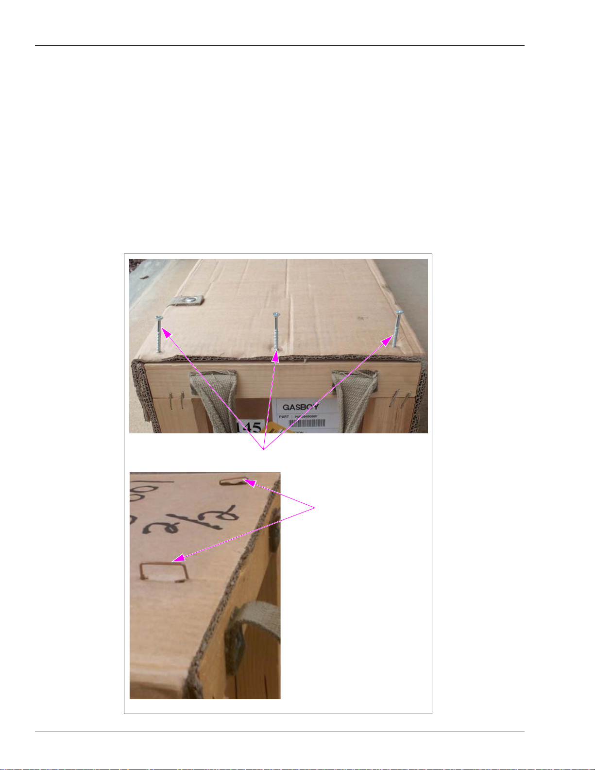
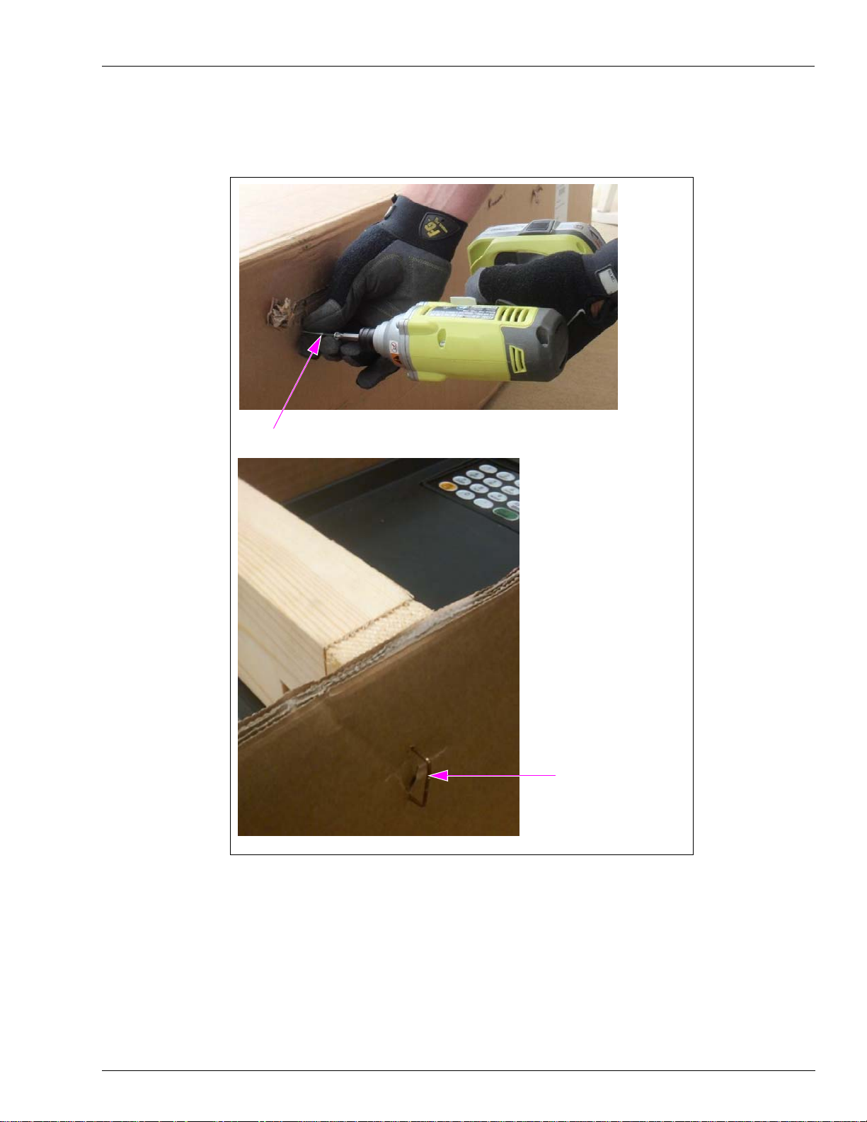
1 Remove the screws/staples from both ends of the box (see Figure 2).
Note: Some boxes will be stapled.
Figure 2: Removing the Screws/Staples
Screws on One End of the Box
(ii)
(i)
Staples
Page 6 MDE-5045 FiPay™ Server Retrofit Kit for 8-hose Islander Installation Guide · January 2013
Page 7
Installing the FiPay Server and Additional Hardware Components in the 8-hose Islander PLUS System
2 Remove the screws/staples from both sides of the box (see Figure 3).
Figure 3: Removing the Screws/Staples
(i)
Screw on Side of the Box
Staple on Side of the Box
(ii)
MDE-5045 FiPay™ Server Retrofit Kit for 8-hose Islander Installation Guide · January 2013 Page 7
Page 8

Installing the FiPay Server and Additional Hardware Components in the 8-hose Islander PLUS System
3 Carefully remove the wooden brace from the box (see Figure 4).
Figure 4: Removing the Wooden Brace
Wooden Brace
4 Remove the Islander PLUS from the box and place on a stable flat surface (see Figure 5).
Figure 5: Islander PLUS
Islander PLUS
Page 8 MDE-5045 FiPay™ Server Retrofit Kit for 8-hose Islander Installation Guide · January 2013
Page 9
Installing the FiPay Server and Additional Hardware Components in the 8-hose Islander PLUS System
Installing the 5-port Switch
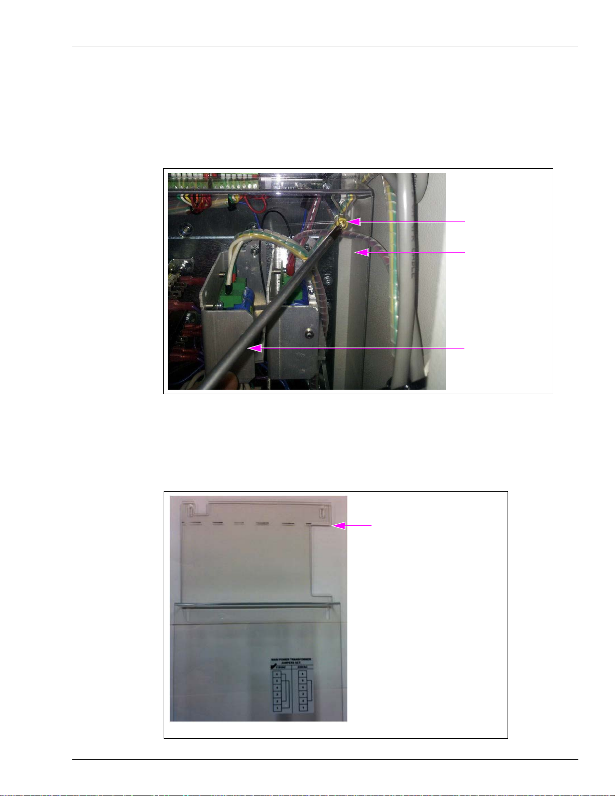
5 Remove the 8-port Protective Panel by removing the six screws using Phillips screwdriver
(see Figure 6).
Figure 6: Removing the 8-port Protective Panel
Screw (6X)
8-port Protective Panel
Phillips Screwdriver
6 Lay the protective cover on a flat surface using a straight edge mark from the bottom-top of
the right side (see Figure 7). After marking the protective cover as shown in Figure 7, cut off
the top using the marks as guide.
Figure 7: Placing the Protective Cover
Bottom-top of the Right Side Cutout
Note: Cut off at ---.
MDE-5045 FiPay™ Server Retrofit Kit for 8-hose Islander Installation Guide · January 2013 Page 9
Page 10

Installing the FiPay Server and Additional Hardware Components in the 8-hose Islander PLUS System
7 Remove the screw on top of the 8-port Commvertor Board using Phillips screwdriver
(see Figure 8).
Figure 8: Removing the Screw
8-port Commvertor Board
Screw
Phillips Screwdriver
8 Install the spacer provided in the M09680B032 Kit. The kit includes two spacers for cases
where the on-board spacer is missing. The washer is required only if both spacers are used.
Note: Spacers are NOT r equired if already installed.
Figure 9: Securing the Spacers
One spacer is already installed.
(i)
Spacer
The second spacer in hand
must be installed.
(ii)
One spacer is already installed. The second spacer must be installed for proper grounding and
proper alignment of the 5-port Switch [see Figure 9 (ii)].
Page 10 MDE-5045 FiPay™ Server Retrofit Kit for 8-hose Islander Installation Guide · January 2013
Page 11

Installing the FiPay Server and Additional Hardware Components in the 8-hose Islander PLUS System
9 Secure the spacers using a 9/32-inch nut driver (see Figure 9 on page 10).
10 Carefully insert the short pins of the Printed Circuit Board (PCB) pin header into the CN8
Connector on the back of the 5-port Switch (see Figure 10).
Figure 10: Inserting the Short Pins
Short Pins
CN8 Connector
11 Connect the 5-port Switch to the 8-port CN14 slot located on the left side of the board.
12 Ensure that the 5-port mounting holes are aligned with the 8-port board mounting holes (see
Figure 11).
Figure 11 : Alignment of 5-port Mounting Holes
13
Check the position of the 5-port Switch. Ensure that it is parallel to the Islander PLUS cabinet
at the top and mechanical pump cards at the bottom.
IMPORTANT INFORMATION
Check the alignment of the 5-port Switch before re-installing the screw. The 5-port
Board must be straight across the top and bottom. The screw hole must be aligned with
the spacer that was installed.
MDE-5045 FiPay™ Server Retrofit Kit for 8-hose Islander Installation Guide · January 2013 Page 11
Page 12

Installing the FiPay Server and Additional Hardware Components in the 8-hose Islander PLUS System
14 Re-install the six screws removed in step 5 on page 9 to secure the 5-port Switch in place.
15 Replace the protective panel. When replacing th e panel, re-install the two screws in the middle
of the panel and two screws in the bottom of the panel (see Figure 12).
Figure 12: Protective Panel
Screws in the Middle
of the Panel
Screws in the Bottom
of the Panel
Page 12 MDE-5045 FiPay™ Server Retrofit Kit for 8-hose Islander Installation Guide · January 2013
Page 13

Installing the FiPay Server and Additional Hardware Components in the 8-hose Islander PLUS System
Installing the Server Bracket
Figure 13: Warning Message
16 Loosen the two screws (top and bottom) from the left-hand side of the protective cover (see
Figure 14). Back the screws out several turns to allow the slotted bracket to be inserted.
Figure 14: Removing the Screws
Screws (2X)
MDE-5045 FiPay™ Server Retrofit Kit for 8-hose Islander Installation Guide · January 2013 Page 13
Page 14

Installing the FiPay Server and Additional Hardware Components in the 8-hose Islander PLUS System
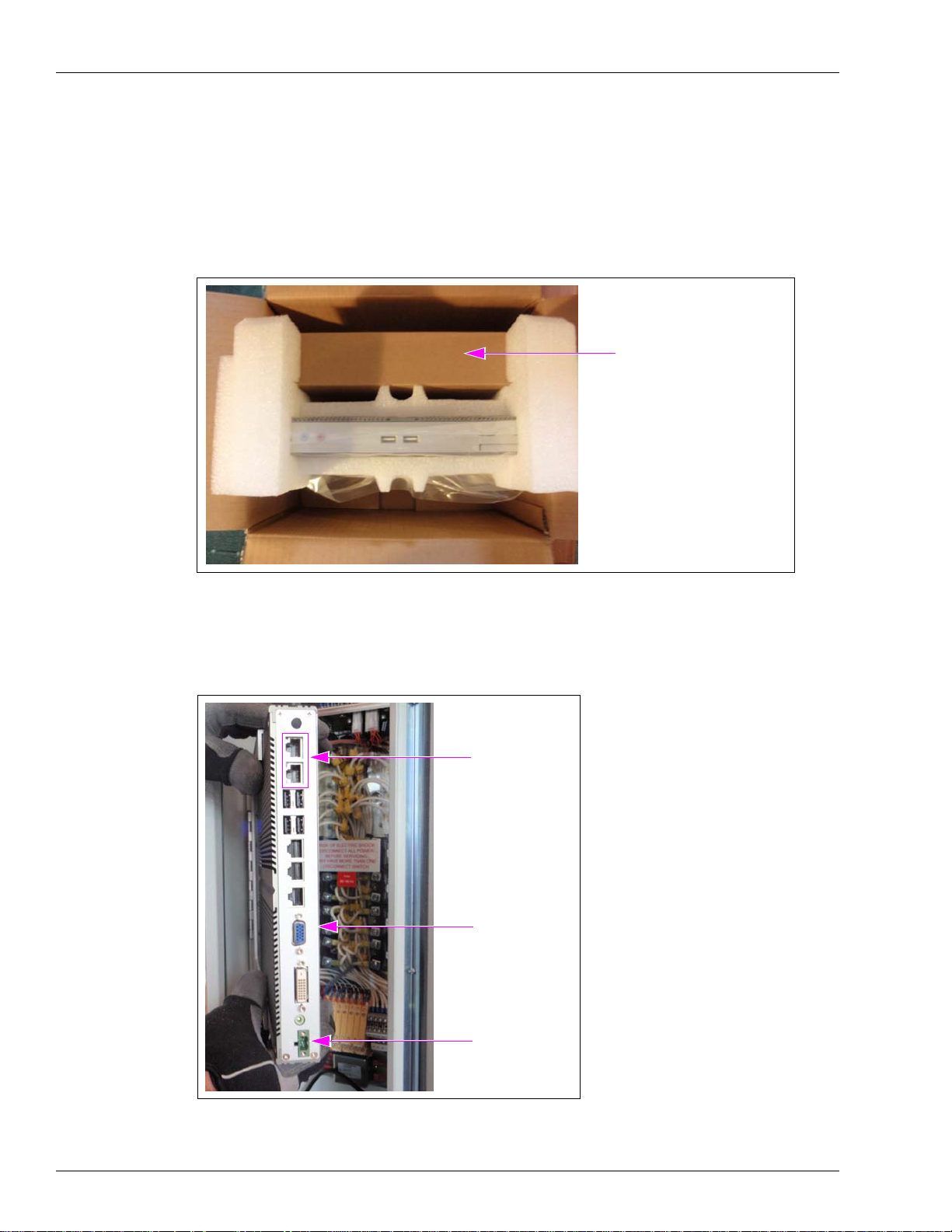
17 Place the bracket in correct orientation. The bracket must swing out to allow the cables to be
connected (see Figure 15).
Figure 15: Placing the Bracket
Bracket
18 Slide the bracket around the screws through the slotted holes, align the screws, and hand
tighten them (see Figure 16).
Figure 16: Sliding the Bracket
(i)
(ii)
Page 14 MDE-5045 FiPay™ Server Retrofit Kit for 8-hose Islander Installation Guide · January 2013
Page 15

Installing the FiPay Server and Additional Hardware Components in the 8-hose Islander PLUS System
19 Secure the bracket, but do not tighten the screws all the way. Slide the bracket back until the
mounting base touches the side of the Islander PLUS cabinet (see Figure 17).
Figure 17: Securing the Bracket
Bracket
20 Tighten the screws to keep the bracket from moving.
MDE-5045 FiPay™ Server Retrofit Kit for 8-hose Islander Installation Guide · January 2013 Page 15
Page 16
Installing the FiPay Server and Additional Hardware Components in the 8-hose Islander PLUS System
Installing the FiPay Server
21 Remove the FiPay Server from the box.
22 Remove the green Phoenix
®
Connector from the second box (see Figure 18).
Figure 18: Removing the Phoenix Connector
DO NOT discard the box.
It contains Phoenix Connector
for PC.
23 Check the orientation of the FiPay Server. The green power connector is at the bottom and
Local Area Network (LAN) Connectors are at the top (see Figure 19).
Figure 19: Orientation of the Seve r
LAN Connectors
FiPay Sever
Power Connector
Page 16 MDE-5045 FiPay™ Server Retrofit Kit for 8-hose Islander Installation Guide · January 2013
Page 17
Installing the FiPay Server and Additional Hardware Components in the 8-hose Islander PLUS System
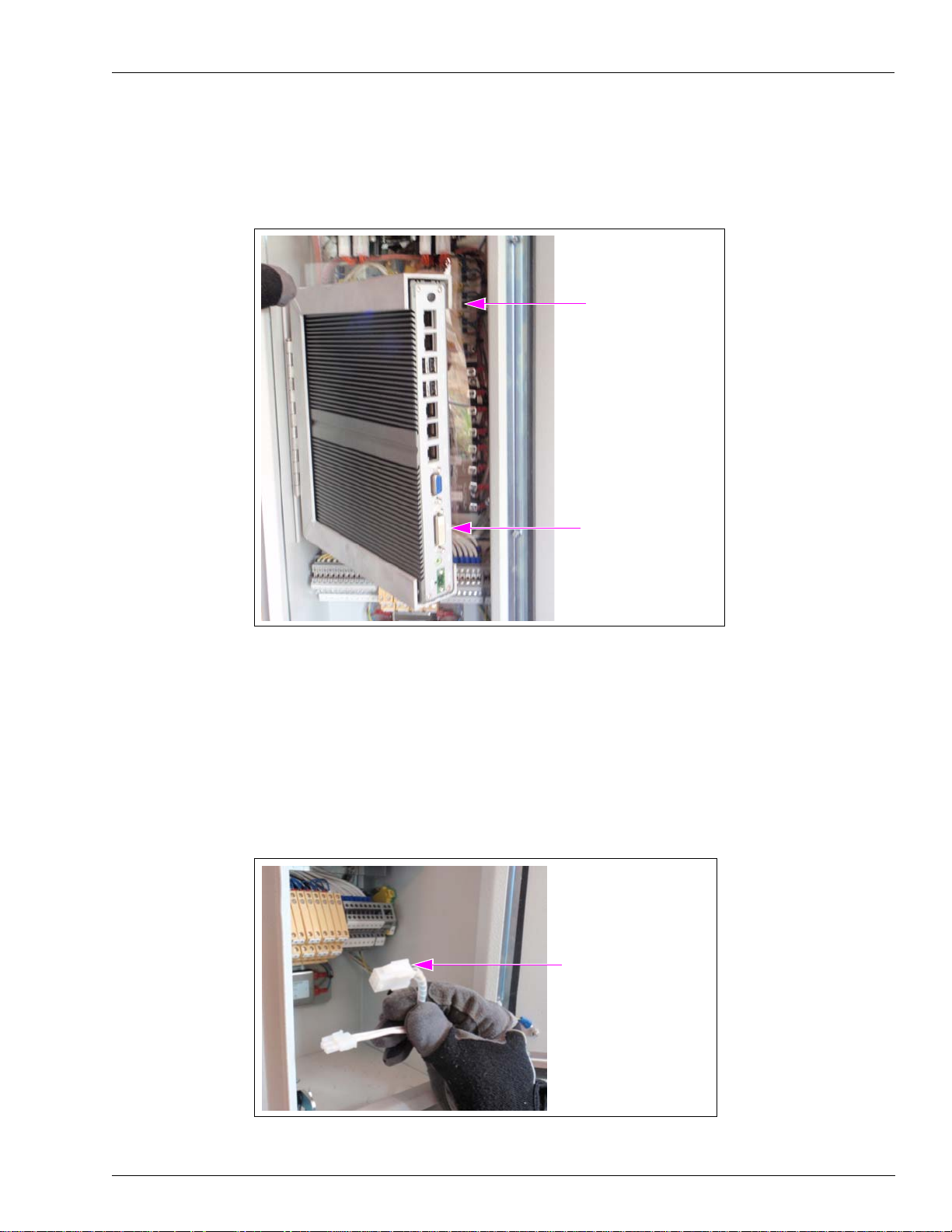
24 Push the FiPay Server into the bracket and ensure that the bracket will clear the Islander PLUS
frame. Adjust the bracket by pushing the mounting base of the bracket back against the side of
the cabinet, if required (see Figure 20).
Figure 20: Adjusting the Bracket
Ensure that the bracket
clears the frame.
25 After checking the clearance, remove the FiPay Server from the bracket and place it in a
secure location.
Wiring the FiPay Server
26 Locate the Receipt Printer Connector at the bottom of the Islander PLUS (see Figure 21).
Figure 21: Receipt Printer Connector
FiPay Server
Receipt Printer Connector
MDE-5045 FiPay™ Server Retrofit Kit for 8-hose Islander Installation Guide · January 2013 Page 17
Page 18
Installing the FiPay Server and Additional Hardware Components in the 8-hose Islander PLUS System
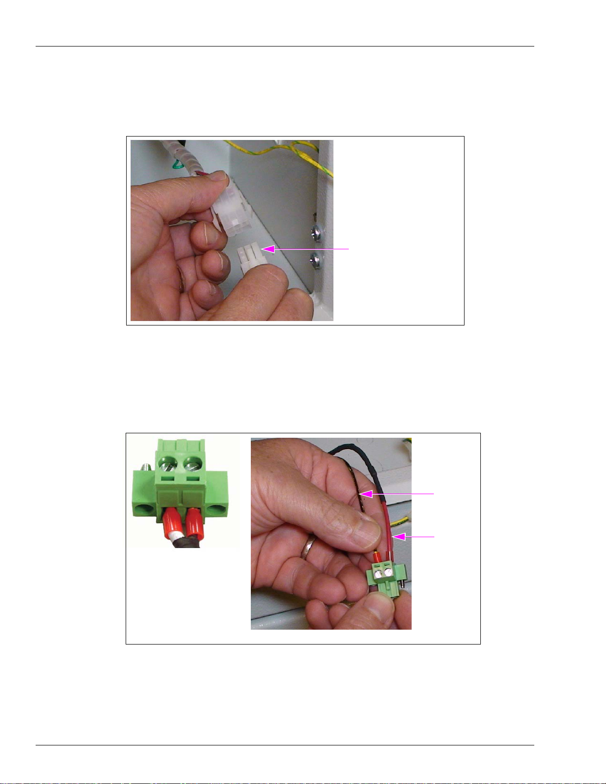
27 Plug the Server power cable assembly into the Receipt Printer Connector (see Figure 22).
Note: Connector is keyed and can be plugged in only one way.
Figure 22: Plugging the Server Power Cable Assembly
Server Power Cable Assembly
28 Locate the Phoenix Connector for the Server.
29 Insert the red fused wire into the positive (+) side and black wire into the negative (-) side of
the Phoenix Connector [see Figure 23 (ii)].
Figure 23: Inserting the Red Fused Wire and Black Wire
Black Wire
Red Wire
+-
(i)
(ii)
The red and black wires are inserted into the Phoenix Connector as shown in Figure 23.
Page 18 MDE-5045 FiPay™ Server Retrofit Kit for 8-hose Islander Installation Guide · January 2013
Page 19
Installing the FiPay Server and Additional Hardware Components in the 8-hose Islander PLUS System
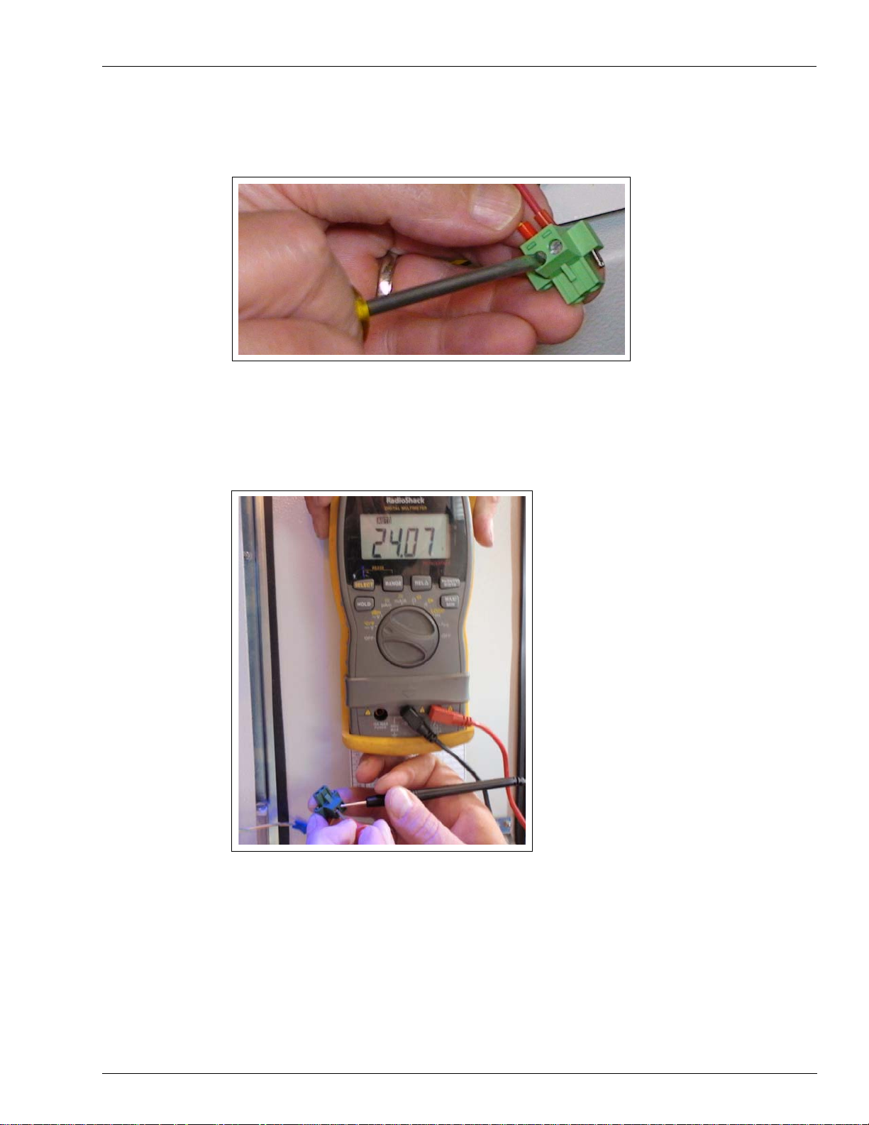
30 Tighten the connectors and check if the wires are secure.
Figure 24: Tightening the Connectors
31 Check the voltage before installing the Phoenix Connector to the Server PC. Ensure that the
voltage is 24 VDC (see Figure 25).
Note: Islander PLUS unit must be powered on.
Figure 25: Checking the Voltage
MDE-5045 FiPay™ Server Retrofit Kit for 8-hose Islander Installation Guide · January 2013 Page 19
Page 20
Installing the FiPay Server and Additional Hardware Components in the 8-hose Islander PLUS System
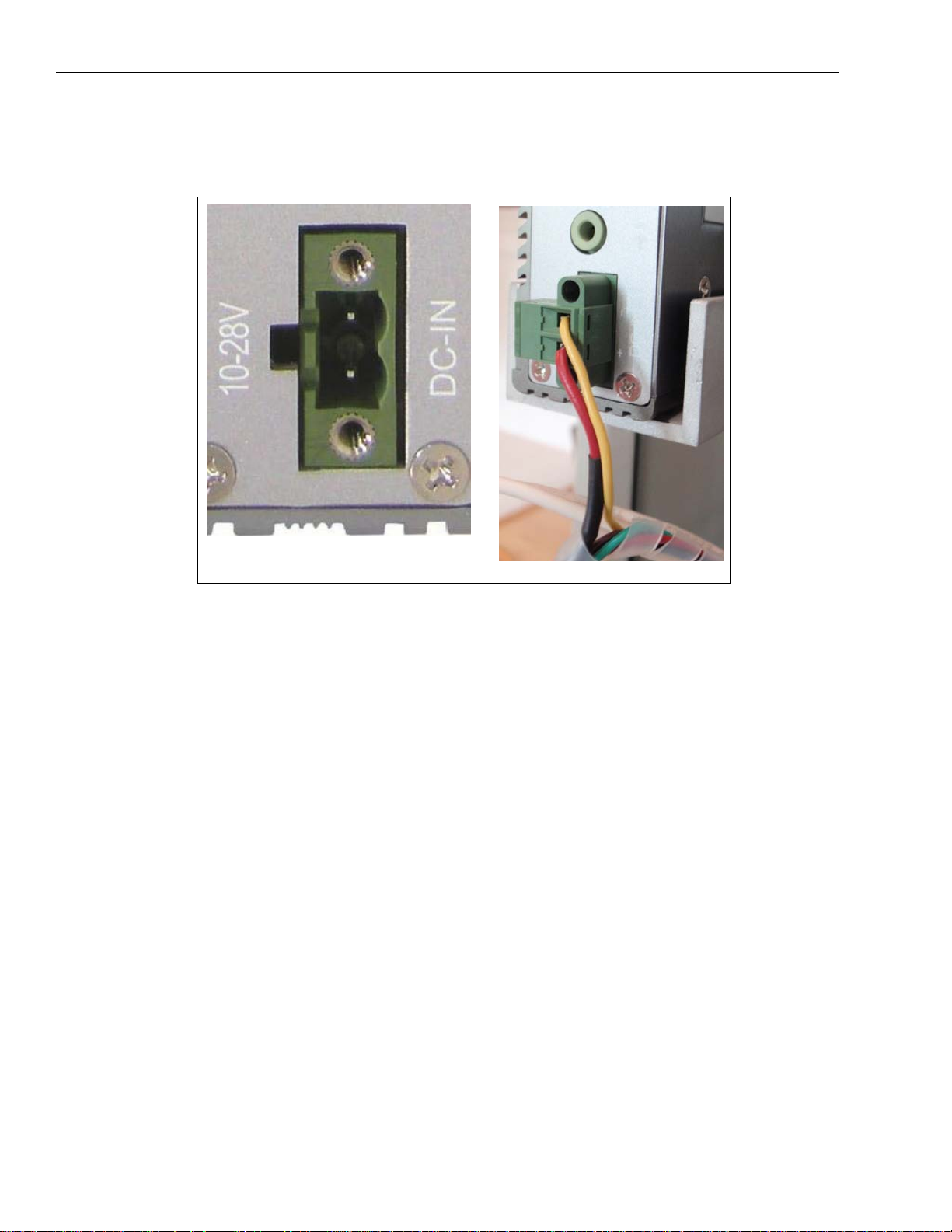
32 After verifying 24 VDC, connect the Phoenix Connector to the Server PC (see Figure 26).
Figure 26: Connecting the Phoenix Connector
(i)
(ii)
Page 20 MDE-5045 FiPay™ Server Retrofit Kit for 8-hose Islander Installation Guide · January 2013
Page 21
Installing the FiPay Server and Additional Hardware Components in the 8-hose Islander PLUS System
Connecting the Ethernet Cables
33 Make the Ethernet connections as shown in Figures 27.
Figure 27: Connecting the Ethernet Cables
MDE-5045 FiPay™ Server Retrofit Kit for 8-hose Islander Installation Guide · January 2013 Page 21
Page 22
Installing the FiPay Server and Additional Hardware Components in the 8-hose Islander PLUS System
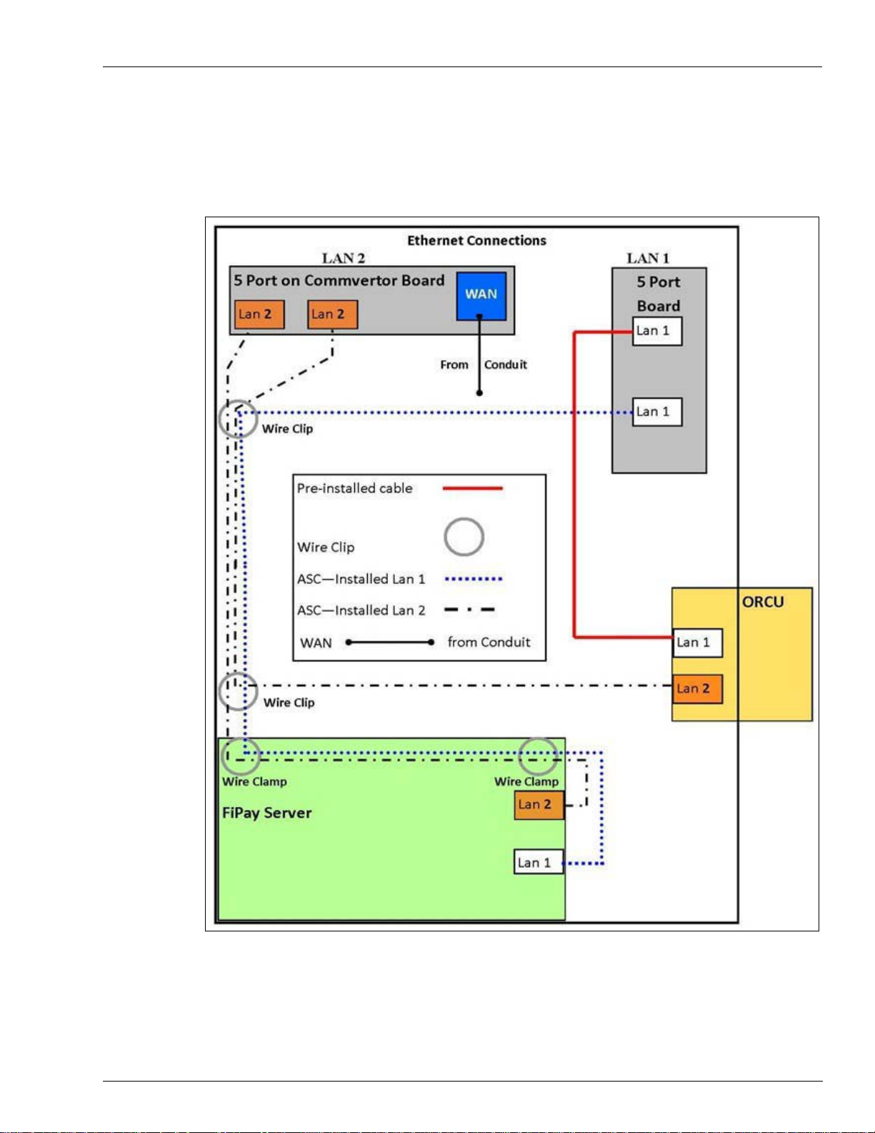
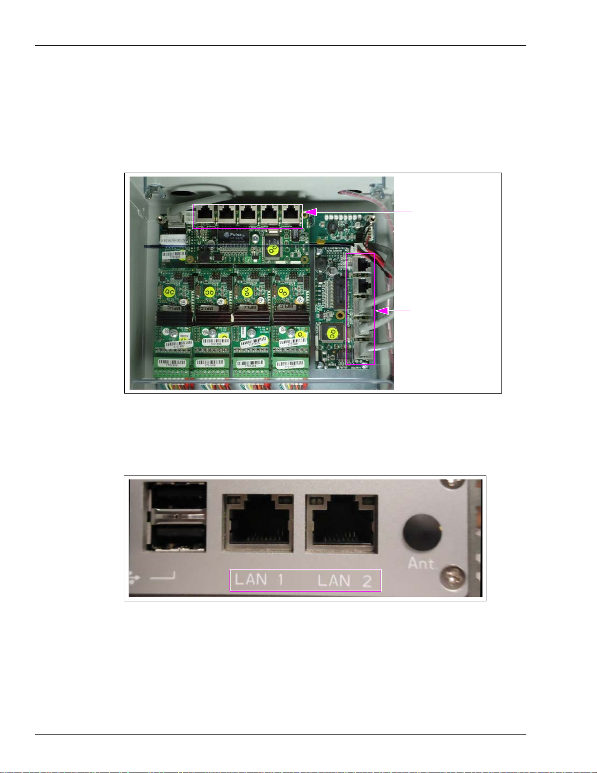
34 FiPay LAN ports and 5-port Switch locations in the Islander PLUS are shown in Figure 28.
• Run cable from LAN 2 of the FiPay Server to the LAN 2 5-port Switch
• R
un cable from LAN 2 of the Orpak Controller Unit (OrC
U) to the LAN 2 5-port Switch
• Run cable from LAN 1 of the FiPay Server to the LAN 1 5-port Switch
• Run cable from the
Figure 28: FiPay LAN Ports and 5-port Switch Location
Wide Area Network [WAN (in cond
uit)] to the LAN 2 5-port Switch
LAN 2 5-port Switch
- FiPay Server LAN 2
- OrCU LAN 2
- WAN
LAN 1 5-port Switch
- FiPay Server LAN 1
To avoid confusion, FiPay Server is clearly marked as LAN 1 and LAN 2 as shown in
Figure 29.
Figure 29: LAN 1 and LAN 2 of Fipay Server
Page 22 MDE-5045 FiPay™ Server Retrofit Kit for 8-hose Islander Installation Guide · January 2013
Page 23
Installing the FiPay Server and Additional Hardware Components in the 8-hose Islander PLUS System
35 Install the wire clips on the TOP of the Server bracket, one at the front and one at the back.
Figure 30: Installing the Wire Clip
Install the wire clip on the top of the
Server bracket.
Note: Ensure that you install the wire
clip with the opening facing out
to allow the Ethernet cables to
be inserted.
36 Insert the FiPay Server Ethernet cables into the wire clips and snap shut.
Figure 31: Inserting the FiPay Server Ethernet Cables
Wire Clips
37 Install the wire clips on the side of the Islander PLUS cabinet.
FiPay Server
Ethernet Cables
MDE-5045 FiPay™ Server Retrofit Kit for 8-hose Islander Installation Guide · January 2013 Page 23
Page 24

Installing the FiPay Server and Additional Hardware Components in the 8-hose Islander PLUS System
38 Place one of the wire clips near the top of the cabinet in line with the bottom of the pump
cards.
Figure 32: Placing the Wire Clip
Wire Clip Near the Top
of the Cabinet
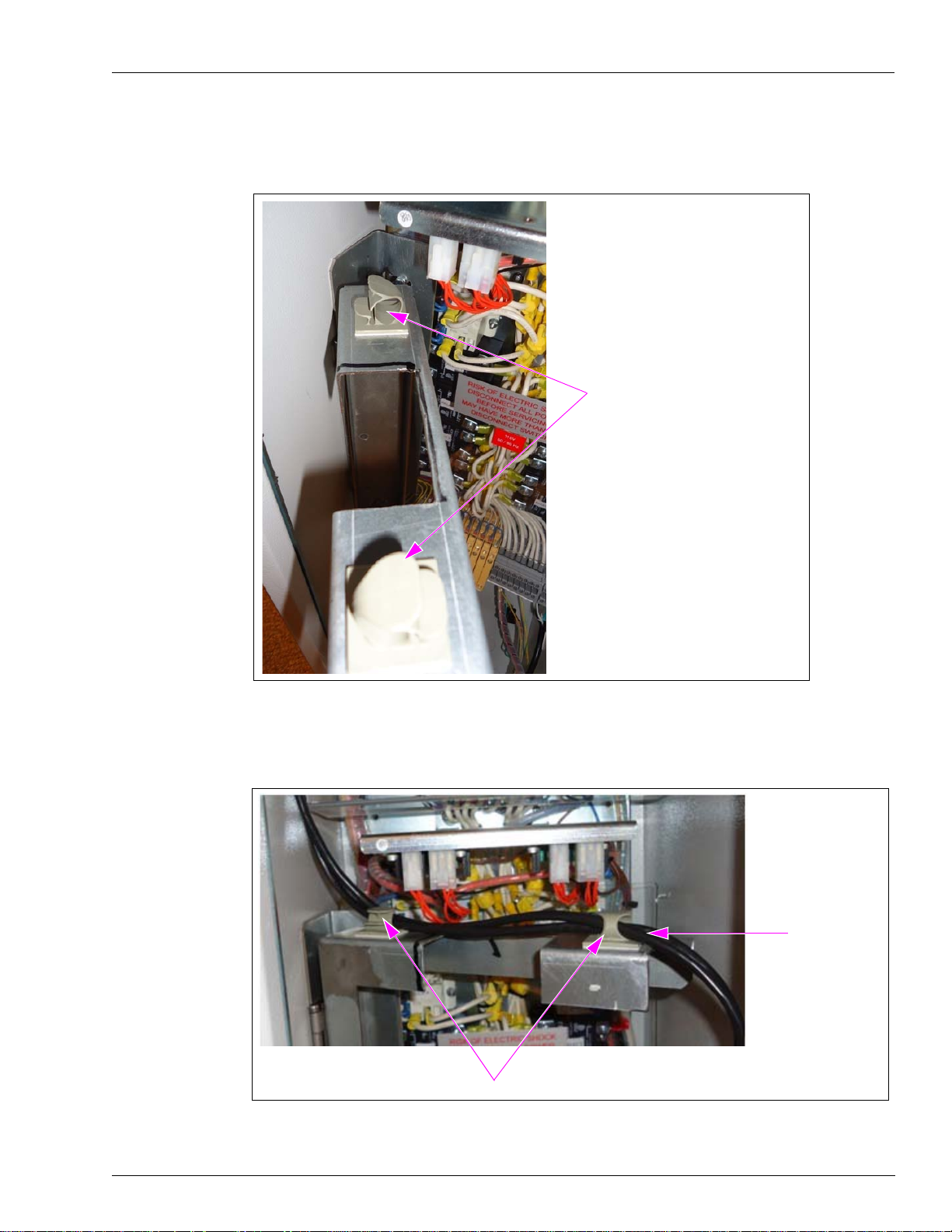
39 Install the second wire clip near the top locking mechanism. Both wire clips are installed as
shown in Figure 33.
40 Insert all the three Ethernet cables into the top wire clip and snap shut (see Figure 33).
Figure 33: Inserting the Ethernet Cables
Ethernet Cables
Wire Clips
Page 24 MDE-5045 FiPay™ Server Retrofit Kit for 8-hose Islander Installation Guide · January 2013
Page 25
Installing the FiPay Server and Additional Hardware Components in the 8-hose Islander PLUS System
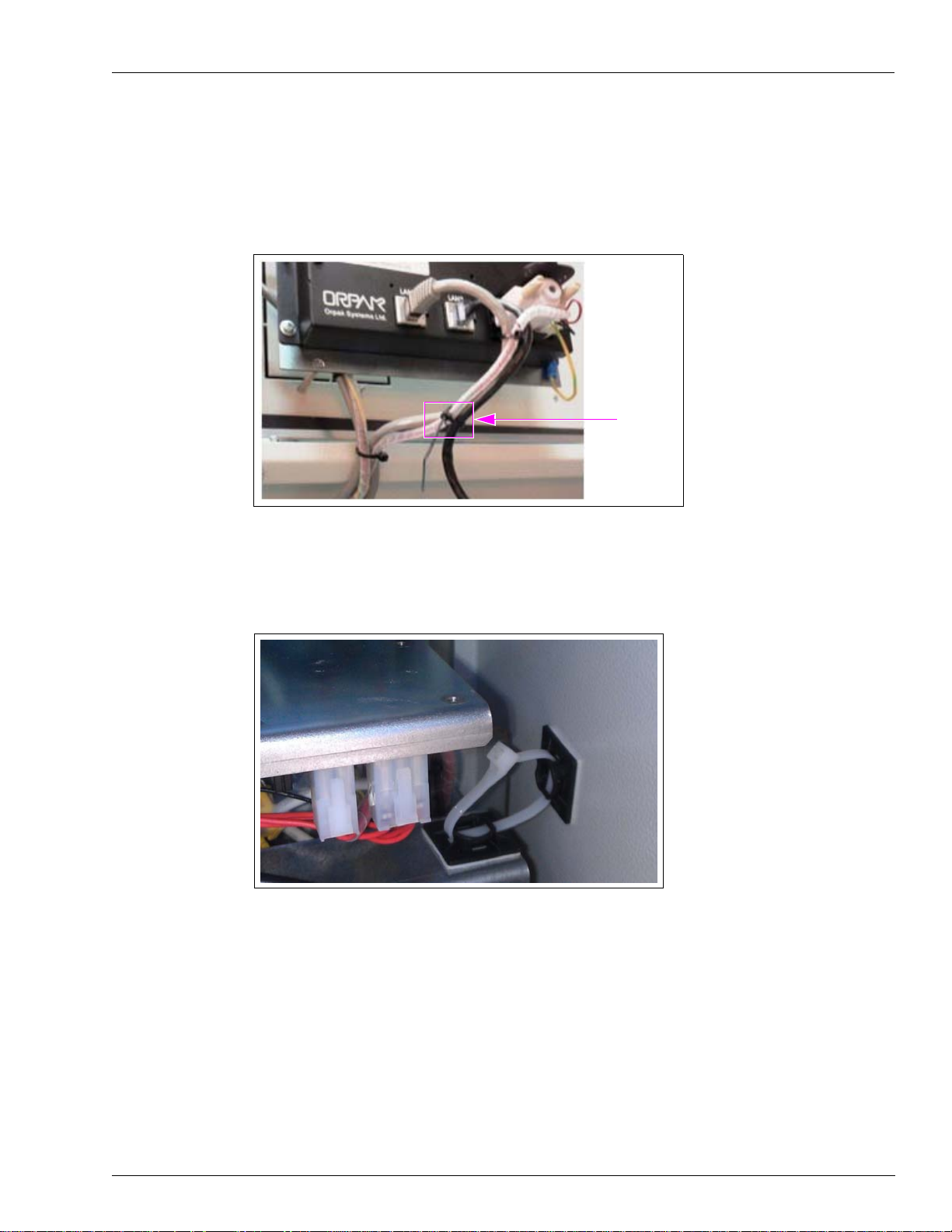
41 Insert all the three Ethernet cables into the bottom wire clip and snap shut (see Figure 33 on
page 24).
42 Tie the LAN 2 Ethernet cable to the LAN 1 Ethernet cable of the OrCU using a cable tie.
Figure 34: Tying the Ethernet Cables
Cable Tie
43 Secure the Server bracket using two staycons and a zip tie, to keep it from moving (see
Figure 35).
Figure 35: Securing the Server Bracket
The installation of the FiPay Server and additional hardware components in the 8-hose
Islander PLUS system is now complete.
MDE-5045 FiPay™ Server Retrofit Kit for 8-hose Islander Installation Guide · January 2013 Page 25
Page 26

CFN® is a registered trademark of FleetCor Technologies Operating Company LLC. Ethernet® is a registered trademark of Xerox
Corporation. FiPay
™
is a trademark of AJB Software Design Inc. Gasboy® is a registered trademark of Gasboy International. Islander
™
PLUS is a trademark of Gasboy International. Orpak™ is a trademark of Orpak Systems Ltd. Phillips® is a registered trademark of The
Phillips Screw Co. Phoenix® is a registered trademark of Phoenix Technologies Ltd. T-Chek™ is a trademark of T-Chek Systems, Inc
© 2013 GASBOY
7300 West Friendly Avenue · Post Office Box 22087
Greensboro, North Carolina 27420
Phone 1-800-444-5529 · http://www.gasboy.com · Printed in the U.S.A.
MDE-5045 FiPay™ Server Retrofit Kit for 8-hose Islander Installation Guide · January 2013
 Loading...