

Page 1

Introduction
M
A
Purpose
This document provides instructions for the installation of a wireless solution in TopKAT™
Online, TopKAT, Series 1000, and Islander II Gasboy
modem helps to avoid trenching and installation of metal conduits for communication wires
between the Gasboy system and the PC system. This document also contains information on
using a Serial-to-LAN converter to communicate with one of the Gasboy systems listed above.
See
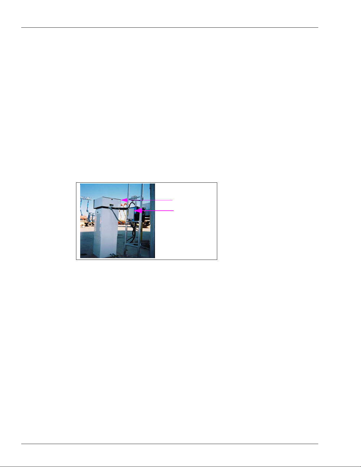
shown in Figure 1.
Figure 1: Gasboy Wireless System - Omnidirectional and Directional Antennas
MDE-4520C
Enhanced Communications Installation Manual
February 2008
®
systems. The installation of a wireless
Serial-to-LAN Connection Installation on page 28. A typical Gasboy Wireless system is
DIRECTIONAL
NTENNA
PRE-MADE 25’
COAX CABLE
MODEM
ENCLOSURE ASSY.
EARTH GROUND
ROD
GASBOY SYSTEM
LIGHTNING
SURGE PROTECTOR
GROUNDING WIRE
VERTICAL
ANTENNA
COAX
EARTH
GROUND
ROD
BUILDING
COAX
GROUNDING
WIRE
RADIO MODE
ENCLOSURE
FEED-THRU
N-CONNECTOR
Notes:1) The distance between the PC system and Gasboy system can be up to 3 miles (4.8
kilometers).
2) If the communication is disrupted between the PC and the Gasboy systems for any
reason, it could take up to 5 minutes to re-initialize.
MDE-4520C Enhanced Communications Installation Manual · February 2008 Page 1
Page 2

Introduction
• The Wireless solution cannot extend communications between Gasboy devices [such as Island
Card Readers (ICR), 9800 series pumps, Gasboy Pump Control Units (PCU)], and other
manufacturer electronic pumps. Also, it is not intended to be used for credit card network
communications.
• The Wireless solution is only intended for point-to-point communication between one PC and
one Gasboy Fuel Management System (FMS) at a time. Multiple Gasboy FMS systems will
require one Base Station kit and one Fueling Position kit for each point-to-point wireless
communication link. An RS-232 A/B has to be locally supplied to switch between the multiple
base stations and Gasboy FMS systems.
Table of Contents
Topic Page
Introduction 1
Important Safety Information 7
Parts Information 9
Site Installation Review and Considerations 13
Site Preparation, Setup Programming, and Testing 20
HyperTerminal Test 25
Serial-to-LAN Connection Installation 28
Appendix: Cable Information 51
IMPORTANT INFORMATION
Required Tools
The following tools are required for the installation of the kit:
Parts List
Fueling Position Wireless Communication Kit (M06544K001)
Description Part Number Quantity
Assembly, Radio Housing M06545A001 1
Bracket, Pedestal to Pole M05844B001 2
Base, Modified TopKAT M05845B001 1
Conduit Fitting M01756A001 1
Tube Flex Conduit Non M01575B003 1
Cable, RS-232/Power To M06543A001 1
Antenna, 8.5 DBD 6 Element M06554A001 1
Cable, Antenna 25 FT Coax M06549A001 1
Sware, Coyote Datacom KS319-001PC 1
• Phillips® Screwdriver
• Soldering Iron and Solder
•Wire Strippers
• Needle Nose Pliers
• Diagonal Cutters
• 3/8 inch Socket Wrench Kit
Page 2 MDE-4520C Enhanced Communications Installation Manual · February 2008
Page 3

Base Station Wireless Communication Kit (M06544K002)
Description Part Number Quantity
Assembly, Radio Housing M06545A002 1
Antenna, 5 DBI Monopole M06553A001 1
Kit, Omni Antenna Mount M06568A001 1
Power Supply M01878B001 1
Lightning Protector M06555B001 1
Genmen Com 1 for Ser Ptr Q13180-20B 1
Cable, Work Area 15 Ft Q13850-15 1
Genmen Coyote Modem Q13180-61 1
Assembly, Mounting Bracket M05971A001 1
Sware, Coyote Datacom KS319-001PC 1
Fueling Position Radio Housing Assembly (M06545A001)
Description Part Number Quantity
NEMA Enclosure, Bud M06546B002 1
Data Radio Module M06551A001 1
Board, Interface RS-232 M06550A002 1
Cable, DB9 To Terminal M06541A001 1
Cable, Radio Power To M06542A001 1
Cable, 13” Coax Reverse M06548A001 1
Lightning Protector M06555B001 1
Assembly, Mounting Bracket M05971A001 1
Bracket, Radio/Modem M05842B001 1
Termn Barrier Strip Q10130-20 1
Bracket, Radio Housing To M05843B001 2
Conduit Fitting M01757A001 1
Cable Assembly, ISL/TOK 12 V Po C07263 1
Introduction
Base Station Radio Housing Assembly (M06545A002)
Description Part Number Quantity
NEMA Enclosure, Bud M06546B002 1
Data Radio Module M06551A001 1
Board, Interface RS-232 M06550A002 1
N-Connector Bulkhead M06572B001 1
Bracket, Radio/Modem M05842B001 1
Suprt Circuit Board Q10651-38 4
Cable, 13” Coax Reverse M06548A001 1
MDE-4520C Enhanced Communications Installation Manual · February 2008 Page 3
Page 4

Introduction
Direct TCP/IP to Serial Interface Kit (M06643K001)
Description Part Number Quantity
25 Pin RS-232 To 10 Base-T M06643B001 1
Label, Ethernet Converter M06727B001 1
Power Supply, Lantronix M06643B002 1
Cable Assembly, RS-232 Modem M/ C04532 1
Serial Tunneling (Direct Connect or Modem Emulation) Interface Kit
(M06643K002)
Description Part Number Quantity
25 Pin RS-232 To 10 Base-T M06643B001 2
Label, Ethernet Converter M06727B001 2
Power Supply, Lantronix M06643B002 2
Cable Assembly, RS-232 Modem M/ C04532 1
DB25M/DB9F Modem Cable Q13240-09 1
Related Documents
Document Number Title GOLD Library
C35963 CFN Series Islander II Installation Manual CFN Series Controllers and POS
MDE-4319 TopKAT Fuel Management System
Installation Manual
MDE-4344 Series 1000 Fuel Management System
Installation Manual
Abbreviations and Acronyms
The following table contains a list of acronyms used in this document.
Term Expansion
AC Alternating Current
ASC Authorized Service Contractor
CFN Cash Flow Network
CD Compact Disk
CDR Call Data Record
COM Communications Port
CSC Customer Specified Contractor
DC Direct Current
DHCP Dynamic Host Configuration Protocol
FCC Federal Communications Commission (http://www.fcc.gov)
ICR Island Card Reader
LAN Local Area Network
NEMA National Electrical Manufacturers Association (http://www.nema.org/)
PC Personal Computer
PCU Pump Control Unit
RF Radio Frequency
RS Request to Send
Series 1000/Fleetkey and TopKAT
Series 1000/Fleetkey and TopKAT
Page 4 MDE-4520C Enhanced Communications Installation Manual · February 2008
Page 5

Intended Users
The intended users of this document are Authorized Service Contractors (ASCs) and
Customer Specified Contractors (CSCs).
Installation Requisites
At each end of the communication loop (namely the fueling position and the PC system), you
require the following:
• One antenna (see note)
• One wireless modem (see note)
• One tower or mast
The basic theory of installation and the guidelines for mounting and placing the antenna,
coaxial cable runs and the parts required, are identical for all systems. The differences between
the two positions is in the programming of the wireless modems at each end of the
communication loop and the RS-232 cables, that are required. For cable details, refer to
Gasboy System End on page 14 and Appendix: Cable Information on page 51.
Notes:1) Currently, you must have one modem at the polling PC for each modem attached to a
Gasboy system (except TopKAT Online). For example, if you have two Series 1000
systems that can be polled from the same PC, you will need two wireless modems at
the polling PC and two antennas.
Introduction
At the
2) The Wireless solution is only intended for point-to-point communication between one
PC and one Gasboy Fuel Management System (FMS) at a time. Multiple Gasboy
FMS systems will require one Base station kit and one Fueling position kit for each
point-to-point wireless communication link. An RS-232 A/B has to be locally supplied
to switch between the multiple base stations and Gasboy FMS systems.
Federal Communications Commission (FCC) Requirements
FCC RF Exposure Statement
This device complies with FCC radiation exposure limits as set forth for an uncontrolled
environment. This device should be installed and operated with a minimum separation
distance of 20 cm (7.87 inches) between the radiator and your body.
FCC Compliance Warning
Changes or modifications to the CDR-915 not expressly approved by Coyote DataCom, Inc.
could void the user’s authority to operate this product.
Note: This equipment has been tested and found to comply with the limits for a Class B digital
device, pursuant to part 15 of the FCC Rules. These limits are designed to provide
reasonable protection against harmful interference in a residential installation.
MDE-4520C Enhanced Communications Installation Manual · February 2008 Page 5
Page 6

Introduction
Warranty
This equipment generates and can radiate radio frequency energy and, if not installed and used
in accordance with the instructions, may cause harmful interference to radio communications.
However, there is no guarantee that interference will not occur in a particular installation. If
this equipment does cause harmful interference to radio or television reception, which can be
determined by turning the equipment off and on, then the user is encouraged to try to correct
the interference by one or more of the following measures:
• Reorient or relocate the receiving antenna.
• Increase the separation between the equipment and receiver.
• Connect the equipment into an outlet on a circuit that is dif f erent from t he circuit to which
the receiver is connected.
• Consult the dealer or an experienced radio/TV technician for help.
For information on warranty, refer to MDE-4255 Gasboy’s Warranty Policy Statement. If you
have any warranty-related questions, contact Gasboy’s Warranty Department at its Greensboro
location.
Page 6 MDE-4520C Enhanced Communications Installation Manual · February 2008
Page 7
Important Safety Information
This section introduces the hazards and safety precautions
associated with installing, inspecting, maintaining or servicing
this product. Before performing any task on this product, read
this safety information and the applicable se cti on s in th is
manual, where additional hazards and safety precautions for
your task will be found. Fire, explosion, electrical shock or
pressure release could occur and cause death or serious
injury, if these safe service procedures are not followed.
Preliminary Precautions
You are working in a potentially dangerous environment of
flammable fuels, vapors, and high voltage or pressures. Only
trained or authorized individuals knowledgeable in the related
procedures should install, inspect, maintain or service this
equipment.
Emergency Total Electrical Shut-Off
The first and most important information you must know is
how to stop all fuel flow to the pump/dispenser and island.
Locate the switch or circuit breakers that shut off all power to
all fueling equipment, dispensing devices, and Submerged
Turbine Pumps (STPs).
!
WARNING
!
The EMERGENCY STOP, ALL STOP, and
PUMP STOP buttons at the cashier’s station
WILL NOT shut off electrical po wer to th e pump/
dispenser. This means that even if you activate
these stops, fuel may continue to flow
uncontrolled.
Important Safety Information
Read the Manual
Read, understand and follow this manual and any other
labels or related materials supplied with this equipment. If you
do not understand a procedure, call a Gasboy Authorized
Service Contractor or call the Gasboy Service Center at 1800-444-5529. It is imperative to your safety and the safety of
others to understand the procedures before beginning work.
Follow the Regulations
Applicable information is available in National Fire Protection
Association (NFPA) 30A; Code for Motor Fuel Dispensing
Facilities and Repair Garages, NFPA 70; National Electrical
Code (NEC), Occupational Safety and Hazard Association
(OSHA) regulations and federal, state, and local codes. All
these regulations must be followed. Failure to install, inspect,
maintain or service this equipment in accordance with these
codes, regulations and standards may lead to legal citations
with penalties or affect the safe use and operation of the
equipment.
Replacement Parts
Use only genuine Gasboy replacement parts and retrofit kits
on your pump/dispenser. Using parts other than genuine
Gasboy replacement parts could create a safety hazard and
violate local regulations.
Safety Symbols and Warning Words
This section provides important information about warning
symbols and boxes.
Alert Symbol
You must use the TOTAL ELECTRICAL SHUTOFF in the case of an emergency and not the
console’s ALL STOP and PUMP STOP or
similar keys.
Total Electrical Shut-Off Before Access
Any procedure that requires access to electrical components
or the electronics of the dispenser requires total electrical
shut off of that unit. Understand the function and location of
this switch or circuit breaker before inspecting, installing,
maintaining, or servicing Gasboy equipment.
Evacuating, Barricading and Shutting Off
Any procedure that requires access to the pump/dispenser or
STPs requires the following actions:
• An evacuation of all unauthorized persons and vehicles
from the work area
• Use of safety tape, cones or barricades at the affected
unit (s)
• A total electrical shut-off of the affected unit (s)
This safety alert symbol is used in this manual and
on warning labels to alert you to a precaution which must be
followed to prevent potential personal safety hazards. Obey
safety directives that follow this symbol to avoid possible
injury or death.
Signal Words
These signal words used in this manual and on warning
labels tell you the seriousness of particular safety hazards.
The precautions below must be followed to prevent death,
injury or damage to the equipment:
DANGER: Alerts you to a hazard or unsafe practice
!
which will result in death or serious injury.
WARNING: Alerts you to a hazard or unsafe practice
!
that could result in death or serious injury.
CAUTION with Alert symbol: Designates a hazard or
!
unsafe practice which may result in minor injury.
CAUTION without Alert symbol: Designates a hazard
or unsafe practice which may result in property or
equipment damage.
Working With Fuels and Electrical Energy
Prevent Explosions and Fires
Fuels and their vapors will explode or burn, if ignited. Spilled
or leaking fuels cause vapors. Even filling customer tanks will
cause potentially dangerous vapors in the vicinity of the
dispenser or island.
MDE-4520C Enhanced Communications Installation Manual · February 2008 Page 7
Page 8

Important Safety Information
No Open Fire
Open flames from matches, lighters, welding
torches or other sources can ignite fuels and their vapors.
No Sparks - No Smoking
Sparks from starting vehicles, starting or using power tools,
burning cigarettes, cigars or pipes can also ignite fuels and
their vapors. Static electricity, including an electrostatic
charge on your body, can cause a spark sufficient to ignite
fuel vapors. Every time you get out of a vehicle, touch the
metal of your vehicle, to discharge any electrostatic charge
before you approach the dispenser island.
Working Alone
It is highly recommended that someone who is capable of
rendering first aid be present during servicing. Familiarize
yourself with Cardiopulmonary Resuscitation (CPR) methods,
if you work with or around high voltages. This information is
available from the American Red Cross. Always advise the
station personnel about where you will be working, and
caution them not to activate power while you are working on
the equipment. Use the OSHA Lockout/ Tagout procedures. If
you are not familiar with this requirement, refer to this
information in the service manual and OSHA documentation.
Working With Electricity Safely
Ensure that you use safe and established practices in
working with electrical devices. Poorly wired devices may
cause a fire, explosion or electrical shock. Ensure that
grounding connections are properly made. Take care that
sealing devices and compounds are in place. Ensure that you
do not pinch wires when replacing covers. Follow OSHA
Lockout/T agout requirements. Station employees and service
contractors need to understand and comply with this program
completely to ensure safety while the equipment is down.
Hazardous Materials
Some materials present inside electronic enclosures may
present a health hazard if not handled correctly. Ensure that
you clean hands after handling equipment. Do not place any
equipment in the mouth.
!
WARNING
The pump/dispenser contains a chemical known to the
State of California to cause cancer.
In an Emergency
Inform Emergency Personnel
Compile the following information and inform emergency
personnel:
• Location of accident (for example, address, front/back of
building, and so on)
• Nature of accident (for example, possible heart attack, run
over by car, burns, and so on)
• Age of victim (for example, baby, teenager, middle-age,
elderly)
• Whether or not victim has received first aid (for example,
stopped bleeding by pressure, and so on)
• Whether or not a victim has vomited (for example, if
swallowed or inhaled something, and so on)
WARNING
!
Gasoline ingested may cause unconsciousness
and burns to internal organs.
Do not induce vomiting.
Keep airway open.
Oxygen may be needed at scene.
Seek medical advice immediately.
WARNING
!
Gasoline inhaled may cause unconsciousness
and burns to lips, mouth and lungs.
Keep airway open.
Seek medical advice immediately.
WARNING
!
Gasoline spilled in eyes may cause burns to eye
tissue.
Irrigate eyes with water for approximately 15
minutes.
Seek medical advice immediately.
WARNING
!
Gasoline spilled on skin may cause burns.
Wash area thoroughly with clear water.
Seek medical advice immediately.
IMPORTANT: Oxygen may be needed at scene if gasoline
has been ingested or inhaled. Seek medical advice
immediately.
WARNING
!
Lockout/Tagout
Lockout/Tagout covers servicing and maintenance of
The pump/dispenser contains a chemical known to the
State of California to cause birth defects or other
reproductive harm.
machines and equipment in which the unexpected
energization or start-up of the machine(s) or equipment or
release of stored energy could cause injury to employees or
personnel. Lockout/Tagout applies to all mechanical,
hydraulic, chemical or other energy, but does not cover
electrical hazards. Subpart S of 29 CFR Part 1910 - Electrical
Hazards, 29 CFR Part 1910.333 contains specific Lockout/
Tagout provision for electrical hazards.
Page 8 MDE-4520C Enhanced Communications Installation Manual · February 2008
Page 9

Parts Information
Parts Supplied by Gasboy
The following table lists the parts supplied by Gasboy and the corresponding explanation.
Parts Explanation
Two Wireless Modem Enclosure Assemblies:
• For Fueling Position (M06545A001).
See Figure 2 on page 10.
• For Base Station (M06545A002).
See Figure 3 on page 11.
Antennas:
• At fueling positions: 6 dB Gain
Directional Yagi Antenna (M06554A001)
• At base stations: 5 dB Gain
Omnidirectional (M06553A001)
Parts Information
• One wireless modem enclosure is used at each end of the
communications loop (see note on
• You must have a copy of the Call Data Record (CDR) Setup
Tools version 2.2 or above (KS319 001PC) to program the
modems. This is provided with the M06544K002 kit. This
software is also available as a free download at
http://www.coyotedatacom.com/support.htm
• Y ou will need a PC capable of running the software, a serial port,
and a DB9 male to female cable to connect the PC to the
wireless modem. The same cable can also be used for a laptop.
Note: This cable is assembled in the field from the following
loose parts shipped in the M06544K002 kit:
- Q13850-15 (cable, work area, 15 feet)
- Q13180-20B (gender mender, 9-pin D-sub to jack)
- Q13180-61 (gender mender, Coyote modem, for
M06551A002)
• The power connection for the wireless modem at the Gasboy
system end is provided by the Gasboy system power supply. For
the wireless modem at the PC end, the power is provided from a
M01878B001 110-volt AC to 12-volt DC transformer block. This
transformer MUST be plugged into the same circuit that provides
power to the PC.
• Gasboy supplies 4 Amphenol (82-202) or its equivalent as the N
style male connector (M06547B001) for use with the Base
station kit coaxial cable runs. Two connectors are needed for
each coaxial cable run. These connectors are sized for the RG8/
U cable diameter. If you use a different cable, you will have to
locally purchase connectors that are sized for the cable installed.
Two of these connector kits are used for the coaxial cable run
from the antenna to the lightning suppressor and two are used
for the coaxial cable run for the lightning arrestor to the Base
station kit. See
page 20 for details.
• Once the system communication is fully tested, these
connections MUST be protected by an appropriate sealing tape
(M06571B001) designed for an all weather environment.
• One antenna will be used at each end of the communications
loop (see note on
• A mounting kit to attach the omni antenna to the antenna mast is
supplied as part of the antenna kit (M06568A001).
• In general, a directional antenna is used at the Gasboy system
end of the communications loop and an omnidirectional antenna
at the PC end of the loop.
• On sites with a single Gasboy system, and where the distance
between antennas is more than 2500 feet (762 meters), the use
of two directional antennas is recommended.
• On sites with a single Gasboy system and line of sight partially
blocked by high voltage transformers, microwave towers or in
the neighborhood of airports, the use of two directional antennas
is recommended if the distance between towers exceeds 1500
feet (457.2 meters).
Assembling the Connector (M06547B001) on
page 5).
page 5).
MDE-4520C Enhanced Communications Installation Manual · February 2008 Page 9
Page 10
Parts Information
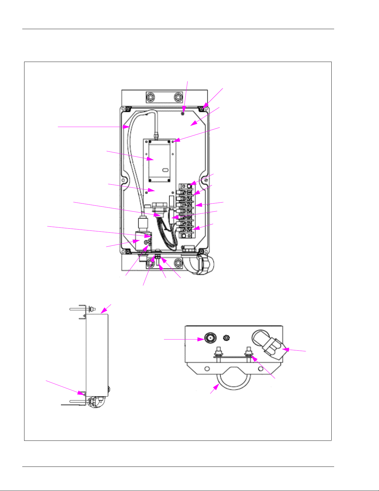
Coax Reverse SMA to N Male
Cable
Data Radio Module
Figure 2: Modem Enclosure - Fueling Position
Screw Metric Pan
Head
Screw SEMS
Mounting Plate Bracket
Circuit Board Support
Hex Screw
Interface Board
DB9 to Terminal Block
Cable
Mounting Bracket - Lightning
Arrestor
Lightning Protector
Side View
Hex Nut
Washer
NEMA Enclosure
Coax N
Connection
Screw
Terminal Strip Barrier
Terminal Block Marker Strip
Radio Power to Terminal Block Cable
Terminal Block - Position 1
Hex Nut
View from below the Enclosure
Conduit
Fitting
Hex Nut w/ Lock
washer
Radio Housing
to Pole Mounting
Bracket
U-bolt and Mounting
Hardware
Washer
Spring Lock
Page 10 MDE-4520C Enhanced Communications Installation Manual · February 2008
Page 11
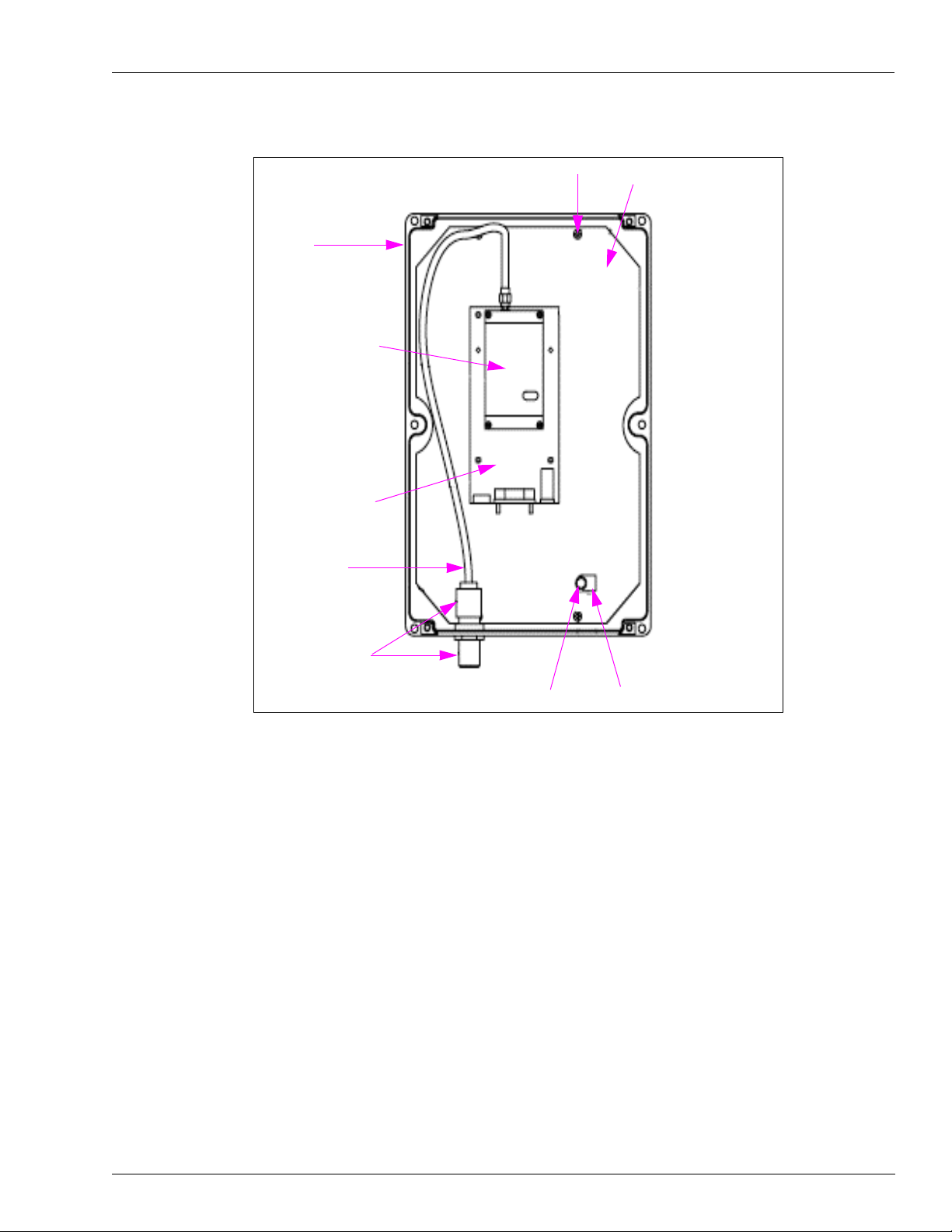
Figure 3: Modem Enclosure - Base Station
Parts Information
NEMA
Enclosure
Data Radio Module
Interface Board
Coax Reverse
SMA to N Male
Cable
Screw Head
Radio/Modem Mounting
Plate Bracket
N-Connector Bulk
Head Adaptor
Hex Screw
Cable Clamp
MDE-4520C Enhanced Communications Installation Manual · February 2008 Page 11
Page 12
Parts Information
Additional Parts Supplied at the Gasboy System End
Parts Explanation
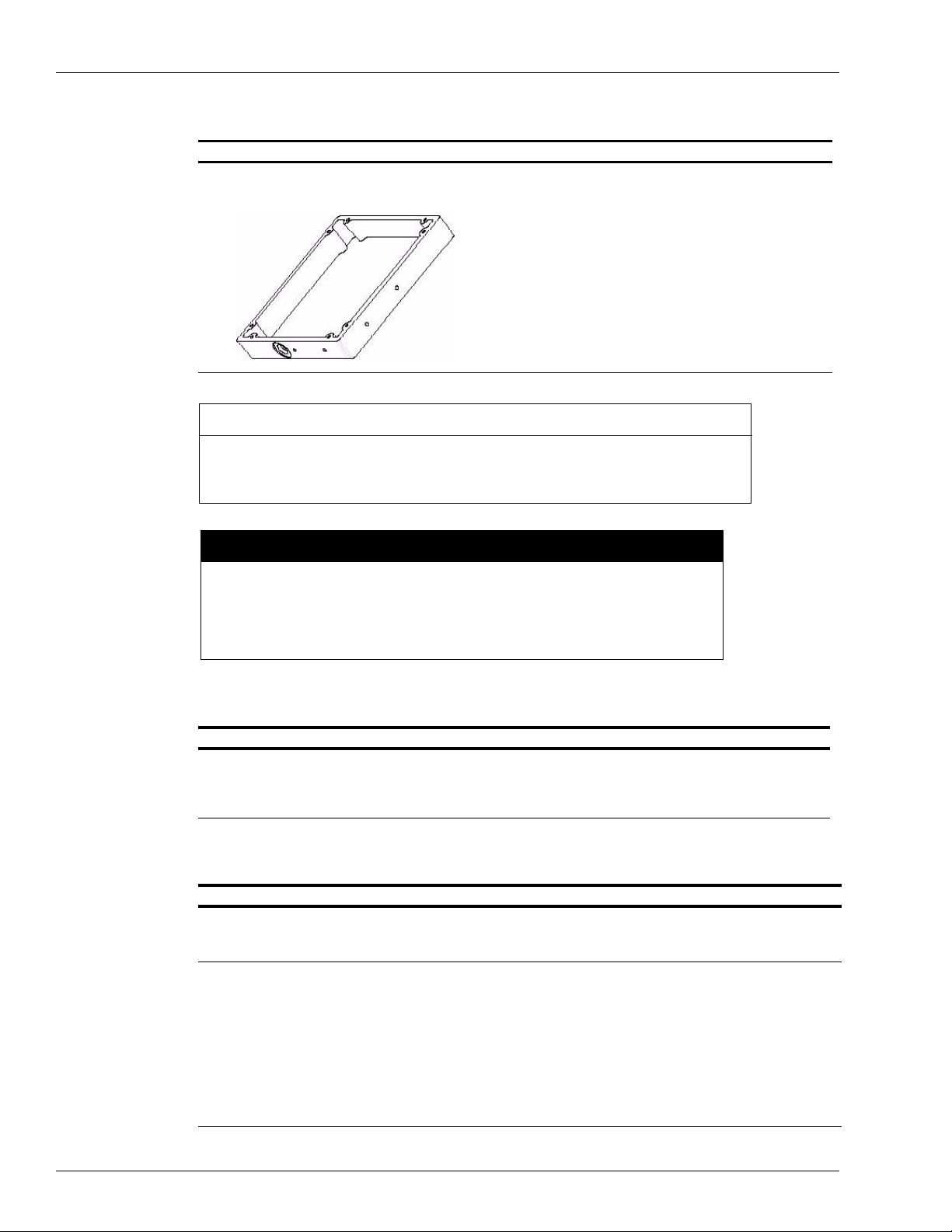
Gasboy TopKAT Riser Collar
(M05845B001)
Under the Gasboy TopKAT on a pedestal, a field-installed
Riser Collar is placed. This collar has one flexible conduit
outlet that is attached directly to the wireless modem
enclosure. In addition, it has the clamp assemblies that
attach the Gasboy TopKAT to one leg of the antenna tower
or mast, and facilitates mounting of the wireless modem
enclosure. This conduit will allow DC power and RS-232
communications between the Gasboy TopKAT and the
wireless modem.
• The RS-232 wiring for the individual Gasboy systems is
Appendix: Cable Information on page 51.
listed in
• The DC power wire provided will work with any system.
It may be cut to length, if needed.
IMPORTANT INFORMATION
Do not use this riser collar for any other Gasboy system. It is only to be used on
pedestal mounted TopKATs. For all other Gasboy systems including TopKATs mounted
on a dispenser, refer to page 14.
CAUTION
The Gasboy pedestal mount TopKAT should be completely removed to install the
collar. Ensure that you fully understand how to replace all disconnected cables, so
that they can be properly reinstalled once the collar is installed, and properly
attached. Failure to do so can cause damage to the system, and is not covered by
the warranty.
Additional Parts Supplied at the PC End
Parts Explanation
RS-232 Communication cable (Q13850-15) See Appendix: Cable Information on page 51 for proper
Parts Not Supplied by Gasboy
Parts Explanation
Towers, Masts, and Mast
Mounting Brackets
Towers or masts at the
Gasboy system end
cable connection.
This is a 15-foot CAT-5 Cable with gender menders at each
end to interface the PC to the Modem Interface Board.
• The distributor is responsible for supplying, and properly installing the towers,
masts, or mast mounting brackets.
• The manufacturer's installation manual MUST be followed.
• Up to a 28-foot tower can be installed at the Gasboy system end without the use of
guy wires. This can consist of a 10-foot tower and a 10-foot mast for a total of 18
feet, or a 20-foot tower and a 10-foot mast for a total of 28 feet.
• The height of the tower is to be determined by the line of sight requirements of the
antenna located on the top of this tower or mast, to the PC wireless modem and its
antenna at the top of its mast or tower.
• An appropriate base plate/mounting bracket to support the tower may be sourced
from one of the following:
– Tally Communication (http://www.talleycom.com/)
– Radian (http://www.radiancorp.com/)
Page 12 MDE-4520C Enhanced Communications Installation Manual · February 2008
Page 13

Site Installation Review and Considerations
Parts Explanation
Mast or tower at the PC end • Usually, a building mast bracket will be used at the PC end for the wireless modem
antenna. This bracket must be mounted such that the antenna is above the roof
line of the building it is attached to.
• Usually, you can install a 10-foot mast which gives an 8-foot height increase from
the point of mounting. Masts taller than 10 feet generally require the use of guy
wires for support.
• If an appropriate mounting to the side or top of the building cannot be located, a
tower may be used.
Coaxial cable and
connectors used between
wireless modem enclosure
and antenna
Conduit If the Gasboy system is not a pedestal mounted TopKAT, conduit from the system
Ground Rods and Ground
Wires
• Gasboy requires the use of RG8 or RG8U coaxial cable. Belden 7810 or its
equivalent meets the Gasboy cable loss requirement. If you are using Belden
7810 or its equivalent, it is recommended that cable lengths do not exceed 150
feet (45.72 meters).
Note: Ensure that the drip loops are provided on all the coaxial cable runs. These
should be provided in such a manner that all connectors, antennas, wireless
modem enclosures and the accesses to the building have a drip loop
installed.
to the wireless modem must be supplied.
• Each tower requires a dedicated ground rod located as close as possible to the
tower or mast.
• The tower and the wireless modem enclosures ground lug for that particular end of
the wireless communication loop MUST be connected to that particular ground rod
only.
• The installed ground rod is connected to the tower or mast and to the wireless
modem enclosure ground lug with a ground wire not less than AWG #4.
Site Installation Review and Considerations
At the PC End or the Building End of the Wireless Communications Loop
Ensure the following for wireless modem placement and coaxial cable runs:
• PC power and wireless modem power MUST come from the same AC circuit. The
wireless modem operates in the 900 MHz range, which is in the same range as some
cordless phones and cell phones. It is recommended not to have a 900 MHz spread
spectrum phone base in the vicinity of the wireless modem enclosure.
• Gasboy provides a 15-foot RS-232 communications cable from the PC to the Wireless
modem. This RS-232 cable can be extended to 50 feet only (15.24 meters) and ONLY in
the metal conduit. Cable shield integrity must be maintained if the cable is extended.
• From the wireless modem enclosure to the antenna, you can run RG8/U coaxial cable to
the antenna. During the length of this cable run, it MUST not be run along with or bundled
to AC conduits, CAT-5, or phone line wires. It may cross over these wires at 90 degrees.
• The antenna must be above the roof line and cl ear of obstructions. This antenna must have
a line of sight view of the antenna mounted at the Gasboy system end of the wireless
communication loop.
• A standard building wall mount mast bracket will only give an 8-foot rise without the use
of guy wires. Gasboy recommends the use of the wall mount at the building so as to not
penetrate the building roof. In Northern climates, ensure that the antenna is placed well
above the roof line so that it does not get buried by snow accumulation.
• Currently, you must have one modem at the polling PC for each modem attached to a
Gasboy system (except TopKAT Online). For example, if you have two Series 1000
systems that can be polled from the same PC, you will need two wireless modems at the
polling PC and two antennas.
MDE-4520C Enhanced Communications Installation Manual · February 2008 Page 13
Page 14
Site Installation Review and Considerations
At the Gasboy System End
Note: The fueling position assembly must be mounted no lower than 18 inches above the
ground and no closer than 18 inches to any fuel dispenser.
Antenna Mast or Tower
• The height of the mast or tower will be determined by the line of sight requirement
between this antenna and the PC wireless antenna.
• You are allowed to use a 10-foot mast, or a 10-foot tower and 10-foot mast (11 feet to 18
feet total height), or a 20-foot 1 or 2 section tower and 10-foot mast (21 feet to 28 feet total
height) without the use of guy wires.
• If a tower base section is used, the manufacturers’ requirements for the installation of that
tower must be followed for the height of the tower installed.
Note: A tower and mast section is preferred as it encloses the wireless modem insi de the
tower and protects it from being damaged.
Figure 4: Modem Inside the Tower
Gasboy System
(TopKAT)
Modem Inside
the Tower
Distance to the Modem Enclosure
For Gasboy systems other than a pedestal mount To pKAT unit, the modem enclosure must not
be more than 20 feet (6.1 meters) away. All other wire and conduit requirements specified in
the system installation manual must be followed.
Note: Do not use collar and conduit supplied with the kit.
Page 14 MDE-4520C Enhanced Communications Installation Manual · February 2008
Page 15
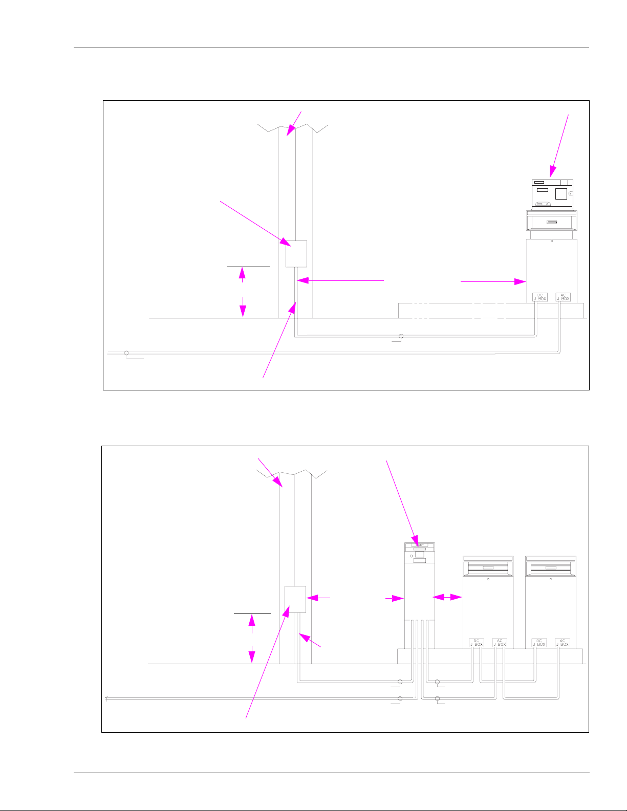
Figure 5: TopKAT Dispenser Mount
Site Installation Review and Considerations
Modem Enclosure Assembly
18” Minimum
AC POWER - SYSTEMS AND PUMPS/DISPENSERS
Conduit (supplied by installer)
Antenna Mast
DC COMMUNICATION CONDUIT
TopKAT
20 Feet Maximum
Figure 6: Gasboy System (Series 1000, Islander)
Antenna Mast
18” Minimum
Conduit (supplied
by installer)
DC COMMUNICATION CONDUIT
AC POWER - SYSTEMS AND PUMPS/DISPENSERS
Gasboy System
20 Feet Max
18” Min
DC RS-485/Pulser
PUMP/DISPENSER AC POWER
Modem Enclosure Assembly
MDE-4520C Enhanced Communications Installation Manual · February 2008 Page 15
Page 16

Site Installation Review and Considerations
Figure 7: TopKAT Mounted on an ASTRA
Antenna Mast
Modem Enclosure
Assembly
18” Minimum
DC COMMUNICATION CONDUIT
Conduit (supplied by installer)
20 Feet Maximum
Connections between the Wireless Modem and a TopKAT Unit
For an installation with a TopKAT unit mounted on a dispenser, connect five of the wires from
the dispenser DC conduit directly to the port (green connector) and connect two others to the
red and black wires on the M06543A001 cable (
M06543A001 cable should be cut short enough so that excess cable is not left in the TopKAT
unit.
If the T opKAT unit is mounted on a 9850 dispenser (that has only six wires in the DC conduit),
connect the black wire from the power supply connector together with the wire connected to
pin 5 of the port connector (green connector). At the modem end, connect that wire to position
5 of the modem terminal block and jumper positions 5 and 7 together.
Figure 8 on page 17). In this case, the
Page 16 MDE-4520C Enhanced Communications Installation Manual · February 2008
Page 17

Site Installation Review and Considerations
Figure 8: Wireless Modem to TopKAT Connections – M06543A001 Cable
TopKAT Power Supply Connection
Wireless Modem
Terminal Block
3
2
7
6
Port Connector
(green connector)
5
4
3
2
1
Wire Colors at Wireless Modem:
7 - black
6 - red
5 - blue
4 - white
3 - brown
2 - green
1 - orange
1
M06543A001 Cable
23
5
4
MDE-4520C Enhanced Communications Installation Manual · February 2008 Page 17
Page 18

Site Installation Review and Considerations
Connections between the Wireless Modem and an Islander
To use the wireless modem with the Islander, you must configure the remote port to be either
port 1 or port 3 (
jumpers (K1 or K2) on the Site Communications I/O board must be configured as shown in
Figure 10.
On the Site Communications I/O PCA, K3 (for port 1) or K4 (for port 3) should not be
jumpered. A C07263 cable (included with the M06544K001 kit) must be installed on the Site
Communications I/O PCA that controls ports 1 and 3. This cable will connect to P10 and pins
6 through 10 of P3 (port 1) or P4 (port 3).
Figure 9: Wireless Modem to Islander Connections
Port 1 (TB5)
Port 3 (TB6)
Figure 9). The Islander CPU K1 (port 1) or K2 (port 3) jumper patch and the
or
1234
5
Figure 10: Jumper Configurations
Site CPU PCA K1 or K2
123
0
1
2
3
4
5
6
7
8
9
A
Wireless Modem
Terminal Block
Site Communication I/O PCA K1 or K2
8
6
4
7
5
3
12
7
6
5
4
3
2
1
Page 18 MDE-4520C Enhanced Communications Installation Manual · February 2008
Page 19

Site Installation Review and Considerations
Connections between the Wireless Modem and a Series 1000 Unit
Figure 11 shows the wiring connections between the wireless modem and a Series 1000
System.
Figure 11: Wireless Modem to Series 1000 Connections
Series 1000
Serial Ports/Pulser Power
Terminal Block
Wireless Modem
Terminal Block
1
P
O
2
R
3
T
4
2
5
1 - 2
3 - 4
5 - 6
7 - 8
PWR
GND
PWR
GND
PWR
GND
PWR
GND
P
U
L
S
E
R
P
O
W
E
R
TXD
DTR
RXD
CD
GND
1
2
3
4
5
6
7
MDE-4520C Enhanced Communications Installation Manual · February 2008 Page 19
Page 20

Site Preparation, Setup Programming, and Testing
Site Preparation, Setup Programming, and Testing
Assembling the Connector (M06547B001)
Parts Required
The following parts are required to assemble a N-plug connector:
•Nut
•Washer
•Gasket
•Clamp
• Male contact
• Plug body
Note: You will need a soldering iron to assemble the connectors.
Figure 12: N-plug Connector Parts
To assemble the N-plug connector, proceed as follows:
1 Place the nut, washer and gasket (with the “V” groove towards the open end of the cable) over
the cable, and cut off the jacket to dimension a.
a = 0.359” (9.1 mm)
c = 0.234” (5.9 mm)
2 Comb out the braid and fold out. Bare the center conductor to dime ns io n c as shown.
Page 20 MDE-4520C Enhanced Communications Installation Manual · February 2008
Page 21

Site Preparation, Setup Programming, and Testing
3 Pull the braid wires forward and taper them towards the center conductor . Place the clamp over
the braid and push it back against the cable jacket.
4 Fold back the braid wires as shown, trim the braid to proper length and form over the clamp as
shown. Tin center conductor and solder on contact.
5 Insert the cable and parts into the connector body. Ensure that the sharp edge of the clamp
seats properly in the gasket. Tighten the nut.
Installing the CDR Tools Software for the Wireless Modem Setup
The CDR Tools Software from Coyote must be used to program the Coyote wireless modem.
This KS319 001PC software is provided with the Base Station kit.
You should load this software on your computer and the Site PC that will be connected to the
wireless modem. When the installation is complete, the Radio Programmer icon appears on
your desktop.
To install the CDR Tools Software, proceed as follows:
1 Insert the diskette into the appropriate drive.
2 Click Start > Run. The Run dialog box appears.
3 Type A:\Setup.
Note: On most computers, the floppy drive is referred to as “A”. If your floppy drive is not
referred to as “A”, type the appropriate letter. The installation process begins.
4 At the License Agreement screen, click Yes.
5 At the Setup Type screen, select Typical and click Next. The copying of files begins.
6 Insert Disk 2 when instructed to do so, and click OK.
7 Click Yes to restart your computer.
MDE-4520C Enhanced Communications Installation Manual · February 2008 Page 21
Page 22

Site Preparation, Setup Programming, and Testing
8 After the PC reboots, connect the appropriate RS-232 cable between the computer COM port
and the wireless modem. See
Appendix: Cable Information on page 51 for cable details.
9 Connect DC power to the modem.
Programming the Wireless Modems
To program the wireless modems, proceed as follows:
1 Click the Radio Programmer icon on your desktop. The Coyote DataCom Radio
Programmer window appears.
Figure 13: Default Coyote DataCom Radio Programmer Window
Destination Group
Source Group
Source Address
Destination
Address
No AckBack
Wait for AckBack
Write
Read
Tx Holdoff Time
Packet Size
Preamble Bytes
CTS De-Assert
CTS Assert
Baud Rate
Note: If you get an error message regarding the COM port, click Utilities > Port Setting and
select the correct port through which you are communicating. The Default setting is
COM 1.
2 Click Read to get Config information from the Modem.
3 Locate the Source Group and Destination Group on the Screen, and set the values to one (1)
for all modems.
Page 22 MDE-4520C Enhanced Communications Installation Manual · February 2008
Page 23

Site Preparation, Setup Programming, and Testing
4 Locate the Source Address and Destination Address, and set the values from the table below.
Note: The values in the table are for PC TopKAT Online Software ONLY using SPECIAL
software in the TopKAT system.
Wireless Modem Source Address Destination Address
PC Modem 100 0
TopKAT Modem Match TopKAT Poll Address 100
Note: The values in the table are for Standar d TopKAT, Series 1000, FleetKey and Islander II
Wireless Modem Source Address Destination Address
PC Modem 100 1
Gasboy System Modem 1 100
Note: Ensure that the auto poll interval (time between successive auto polls) is set to ten (10)
minutes.
5 Locate the box labeled Tx (upper right corner of screen), and set the values from the table
below.
Tx Holdoff Time Packet Size Preamble Bytes
PC TopKAT Online 5 ms (default) 177 (default) 400 or 266 (default)
For all other Gasboy
Systems
200 ms (default) 150 (default) 266 (default)
(default for 2400 baud)
6 Locate Acknowledgement Packet Box.
• “No AckBack” should be selected for sites with multiple PC T opKAT Online systems and
all other Gasboy systems.
• “Wait for AckBack” may be selected for sites with only one PC TopKAT Online system.
Note: Both modems MUST be set to the same option for the modems to function properly.
7 Locate Communications Port Box, and set the values from the table given below.
.
CTS De-Assert CTS Assert Baud Rate
PC TopKAT Online 178 (default) 89 (default) 9600
For all other Gasboy
systems
178 (default) 89 (default) 2400
CAUTION
4800 baud and 9600 baud must not be used for other Gasboy systems. Use of baud rates
higher than 2400 baud will cause modem buffer overflow and the Gasboy system will sign off
prematurely.
Note: Both modems MUST be set to the same value. Baud rate MUST match the Gasboy PC
software baud rate setting.
8 Click Write to save the values entered.
9 Click Read to verify the values entered have been saved correctly.
MDE-4520C Enhanced Communications Installation Manual · February 2008 Page 23
Page 24

Site Preparation, Setup Programming, and Testing
Additional notes for PC TopKAT Online software:
Notes:1) During background polling, the destination address of the modem connected to the
PC will be set by the PC TopKAT Online software to zero (0). This setting will allow
the modem to issue a broadcast command that can be heard by all modems at the
TopKAT systems. Only the TopKAT with the correct poll address will respond to the
command.
2) When the user selects the “Contact a TopKAT” option, the PC TopKAT Online
software will set the destination address of the modem connected to the PC to the
value of the poll address for the selected TopKAT site, and turn on the “AckBack”
option. This will ensure that only the requested TopKAT systems respond to the
entered commands.
3) The PC TopKAT Online software package is specifically designed to allow up to 32
TopKAT systems running specific TopKAT software and controlled by one PC via a
wireless modem.
Radio Programmer Utilities – Spectrum Analyzer
The Radio Programmer software includes the Spectrum Analyzer, which helps you look at the
signals and strengths in the vicinity of your modem.
To access the Spectrum Analyzer, proceed as follows:
1 Ensure that the Gasboy PC software has been closed or shut down; also ensure that the
HyperT erminal session is not running.
2 From Coyote DataCom Radio Programmer window, click Utilities.
3 Click Path Management.
4 Select Spectrum Analyzer.
5 Click START. The signals around your site, which fall into the same spectrum as that of your
wireless modem are read.
Setting Up a Microsoft HyperTerminal for Testing and Troubleshooting
To set up a Microsoft HyperTerminal for testing and troubleshooting, proceed as follows:
1 Open the HyperTerminal (included with most versions of Microsoft Windows software).
2 Create a new connection and use the same port and baud rate as you did for the Gasboy PC
software package.
3 Other Communications setting should be set for 8 data, none/no for parity and 1 stop bit. Flow
control should be “none” for TopKAT and Series 1000 and Xon/Xoff for Gasboy CFN
systems.
4 Terminal emulation should be set to Auto detect.
5 It is recommended that you name and save this as “Gasboy Hyper Connect.”
6 Create a shortcut and place it on the Windows desktop next to the Gasboy PC Software icon
and Radio Programmer icon.
Page 24 MDE-4520C Enhanced Communications Installation Manual · February 2008
Page 25

HyperTerminal Test
Testing the Gasboy System Remote Port
It is recommended that the Gasboy remote port be tested, if possible, with a laptop PC or
terminal before connecting the wireless modem system. Use the same HyperTerminal setup as
listed above. Ensure that the remote port baud rate is properly set up as per the appropriate
Gasboy system Operator or Start up manual. Ensure that the Gasboy port is set up for RS-232
communication and NOT RS-485 communications.
Refer to Appendix: Cable Information on page 51 for Laptop to Gasboy System RS-232
cables.
HyperTerminal Test
Connecting and Testing PC to Gasboy System Communications with the Wireless Modems Connected
At this point, you should have programmed the wireless modem and tested the Gasboy system
remote port, if possible. CDR Tools should be loaded on both the PC end of the
communications loop and a laptop PC. You should have HyperTerminal set up (with the
proper configuration explained above) on both the PC and a laptop PC, if possible. These are
necessary if problems arise during communication testing.
To test PC to Gasboy system communications with the wireless modems, proceed as follows:
1 Connect the wireless modems at both the PC and Gasboy system using the supplied cables.
Ensure the cable used to connect the PC to the wireless modem matches the cable listed in
Appendix: Cable Information on page 51. Ensure that the Gasboy system cabling matches the
system cabling as shown in Figure 8 on page 17, Figure 9 on page 18 , and Figure 11 on page
19.
2 Install and connect the power pack at the PC end, and connect the DC cable at the Gasboy
system end, if you have not done so already.
3 Connect the coaxial cable from the wireless modems to the antennas installed at either the
mast or tower. Check to ensure that the mast, towers, and modems are properly grounded.
4 Open up the previously set up HyperTerminal, and test the communication between the PC
and the Gasboy system. After confirming this communication link, close the HyperTerminal
session. You are ready to test the Gasboy software package.
MDE-4520C Enhanced Communications Installation Manual · February 2008 Page 25
Page 26

HyperTerminal Test
Diagnosing Wireless Modem Installation and Setup Issues
If there is no communication with the Hyper Terminal or the Gasboy PC Package, proceed as
follows:
1 Verify both modems have been properly configured and the proper cables are installed and the
connections are tested. Set the modems to the default parameters before programming.
2 Verify the coaxial connectors have been properly installed and do not short out the entire
cable.
3 For ALL STANDARD Gasboy Fuel Management systems (Standard TopKAT, 1000 series,
FleetKey and Islander II) the baud rate for all devices MUST BE 2400 BAUD. Verify the FMS
system remote port is set for 2400 baud, both modems are set for 2400 baud and the Gasboy
PC Software Package is set for 2400 baud.
Note: For the Gasboy PC TopKAT On Line softwar e ONL Y verify the TopKAT communication
port is set for 9600 baud, both modems are set for 9600 baud and the PC To pKAT On
Line software is set for 9600 baud (the TopKAT system will also have special software
for use with this software package).
4 Verify the wireless modem settings for the system and software on the site are as per the charts
provided in this manual (refer to
5 If the wireless communications is intermittent, for example, if you receive a few characters or
Programming the Wireless Modems on page 22).
one or 2 lines, once again check the modem programming. Ensure that other than the source
and destination address the setup is identical. Ensure that “No Ack Back” is selected and
“Preamble Bytes” is set to 266.
6 “In Manager Mode” may appear on the Gasboy PC Software package screen when subsequent
attempts to “Contact the Site” or “Polling Session” are initiated. The time period this can occur
in is approximately 5 minutes. This has been so far only noted with the standard Gasboy PC
T o pKAT software. It is caused by the way the wireless modems ends the “Contact the Site” or
a “Polling Session”. To avoid this, ensure that the auto poll interval is set to 10 minutes. To
clear this state, contact the site with Hyper Terminal and then end the session with the “EX”
command.
7 If the wireless modems work properly with Hyper Terminal but report an error with the
Gasboy Software package, for example, a “No DCD signal” use the signal tests below.
Page 26 MDE-4520C Enhanced Communications Installation Manual · February 2008
Page 27

Coyote Modem and Communication Port Signal Testing
Note: The CDR 915 is compatible with the CDR 9150 modem. With the differences noted
below.
• When the modem is plugged into power, it should show a YELLOW light on the front
near the connector. It should also flash the GREEN light approximately once per second
even if no second modem is in the area.
• If the green transmit light is not flashing, plug and unplug the power connector to the
modem. This can happen if the communication cable is inadvertently disconnected and
reconnected. If this continually happens, use an ohm meter to verify point-to-point
connection, if necessary.
• The pin outs are referenced to a 9 pin connector for voltage measurements. Refer to the
Figure 14 on page 28 if conversion to 25 pin outs need to be made.
• The CDR 9150 does not provide Pin 1 DCD. It provides the Pin 6 (DSR) and Pin 8 (CTS)
signals. Sites that are replacing a CDR 915 with a CDR 9150 must ensure they order the
new cable listed in Appendix A,
Q13180-20B and Q13180-61) on page 51or modify the existing cable to provide the Pin 1
to Pin 6 jumper as shown in the table on page 51.
• The signals between Gasboy system and modem or between PC and modem may be
verified by the use of an RS-232 Breakout box. An LED will verify the presence of the
individual signals. They may also be measured using a Digital Volt/Ohm Meter. Ensure
that you do not short the pins. Those voltages are provided below. The wireless modem
need not be connected to a PC or Fleet system for the tests below. If the wireless modem
does not provide the proper communications signals, it indicates a bad modem and a new
one should be ordered.
• Use Pin 5 for signal ground.
• If measured at the modem (no cable attached):
- Pin 1 (DCD) is measured to be 6.8 VDC nominal (CDR 915 ONLY).
- Pin 6 (DSR) is measured to be 6.8 VDC nominal.
- Pin 8 (CTS) is measured to be 6.35 VDC nominal dropping to below 6 VDC when the
GREEN transmit light flashes on the CDR 915.
• When you are using the cable mentioned in Appendix: Cable Information on page 51 with
Pins 1 and 6 jumpered internally, the voltage will be 6.35 VDC nominal if measured at the
9 pin connector that will plug into the PC.
• These voltages may vary slightly due to the meter used.
• The PC needs to provide two communication signals. To test these signals a
communications program such as Hyper Terminal must access the communication port to
be tested.
Note: The Coyote Radio Programmer software only provides the DTR signal.
• Pin 4 (DTR) Hyper Terminal and Coyote Radio Programmer software .
• Pin 7 (RTS) Hyper Terminal software only.
• Both of these signal should measure 5.5 VDC nominal.
• If these two signals are not properly provided by the PC's communication port, a problem
with the PC communications port is indicated. Use a second port on the PC if available.
Have the PC repaired as necessary.
• With the Wireless modem connected to the PC, all five signals (DCD, DSR, CTS, DTR
and RTS) must be present for the Gasboy software to properly work with the wireless
modem. All five signals are not easily verified with the cables connected without the use
of a RS-232 breakout box.
PC to Wireless Modem (Cable made up of Q13850-15,
HyperTerminal Test
MDE-4520C Enhanced Communications Installation Manual · February 2008 Page 27
Page 28

Serial-to-LAN Connection Installation
Figure 14: Serial (RS-232) Port Interface Pinout and Signals Chart
Serial (RS-232) port interface pinout and signals
9
pin #
3 2 TxD Transmit Data —» Transmits bytes out of PC
2 3 RxD Receive Data «— Receives bytes into PC
7 4 RTS Request To Send —» RTS/CTS flow control
8 5 CTS Clear To Send «— RTS/CTS flow control
6 6 DSR Data Set Ready «— Modem ready to communicate
4 20 DTR* Data Terminal Ready —» Terminal ready to communicate
1 8 DCD Data Carrier Detect «— Modem connected to another
9 22 RI Ring Indicator «— Telephone line ringing
5 7 SG Signal Ground
*Not provided on CDR9150
25
Acronym Full name Direction Mean
pin#
Serial-to-LAN Connection Installation
Serial-to-LAN Configuration Options
There are two options when connecting Gasboy systems to the Serial-to-LAN adapter.
Note: In most cases, a C04532 cable (included with the kit) will be needed to connect the
Serial-to-LAN adapter to the Gasboy Sho rt Haul Modem (C05618) or Gasboy
Termination Box (C05769).
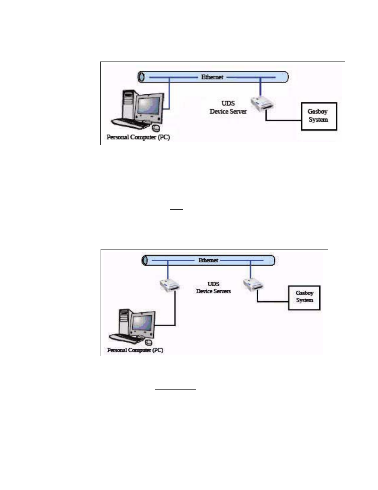
TCP/IP Configuration (use M06643K001)
The first option is to use only one adapter in a Transmission Control Protocol/ Internet Protocol
(TCP/IP) configuration (
one of the Gasboy system’s ser ial ports. The user then uses a PC utility such as Telnet to open
a TCP/IP communication session to the Gasboy system. In this configuration, no serial port is
needed at the PC. With each adapter assigned its own IP address, one PC can be used to
communicate to multiple Gasboy systems (one at a time).
Note: This configuration does not work with the Gasboy PC packages.
Figure 15 on page 29). With this option, the adapter is connected to
Page 28 MDE-4520C Enhanced Communications Installation Manual · February 2008
Page 29
Serial-to-LAN Connection Installation
Figure 15: TCP/IP Configuration
Serial Tunneling Configuration (use M06643K002)
The second option is known as the Serial Tunneling configuration (Figure 16). In this
configuration, one adapter is connected to one of the Gasboy system’s serial ports and a
second adapter is connected to a serial port on the PC.
Note: This configuration works with Gasboy PC packages (such as PC/TopKAT, PC/1000,
PC/CFN).
Figure 16: Serial Tunneling Configuration
The Serial Tunneling configuration has two modes: Direct Connect and Modem Emulation.
• When using the Direct Connect mode, the adapters create a direct connection between the
PC and the Gasboy system that works as if the two (PC and system) had been hard-wired
together. When the adapters are powered up, they establish a TCP/IP link between them.
From that point on, anything transmitted from the PC serial port is sent directly to the
Gasboy system serial port and vice versa. Using this mode, communication can only be
established with one Gasboy system.
MDE-4520C Enhanced Communications Installation Manual · February 2008 Page 29
Page 30

Serial-to-LAN Connection Installation
• When using the Modem Emulation mode, the adapter connected to the PC emulates a
modem. The PC sends AT commands and the adapter responds as if it were a modem.
However, instead of a phone number, the user must use the Gasboy system adapter IP
address and port number (refer to
number to dial. When the IP address and port number are dialed, the adapters establish a
TCP/IP link between them. At this point, they work the same as in Direct Connect mode,
sending and receiving data to and from the serial ports. When the “call” is over, the
adapters drop the TCP/IP connection. Using this mode allows one PC to communicate to
multiple Gasboy systems (one at a time).
Adapter Connections
The Serial-to-LAN adapter (Figure 17) has a standard RJ45 Ethernet port (10Base-T), and
serial port and power connection. The Ethernet port is connected to a standard Ethernet hub or
LAN distribution point, usually with a CAT-5 cable.
For power, connect the AC power supply to the power plug and plug in the AC supply into an
outlet.
Accessing Adapter Parameters on page 32) as the
Figure 17: Serial-to-LAN Adapter
Note: The Reset Switch does not exist on
newer black adapter boxes.
For RS-232 wiring from the Gasboy system (Series 1000, TopKAT, or Islander) to the serial
port, see
Figure 18 on page 31, Figure 19 on page 31 and Figure 20 on page 31.
Note: The terminal blocks on different Gasboy systems may appear different from the ones
shown here, but the point-to-point connections and cables are the same. All
requir ements for RS-232 and RS-422 defined in the Gasboy system installation manuals
apply to the wiring between the system and Serial-to-LAN adapter as well.
Page 30 MDE-4520C Enhanced Communications Installation Manual · February 2008
Page 31

Serial-to-LAN Connection Installation
Figure 18: RS-232 D-Type Connector
100 FEET MAX.
1
2
3
4
5
TXD
DTR
RXD
CD
GND
Figure 19: RS-232 Gasboy Termination Box
100 FEET MAX.
1
2
3
4
5
TXD
DTR
RXD
CD
GND
1
GASBOY
RS232
2
3
4
5
C05769
MODEM CABLE
P/N C04532
P/N C05758
2
20
3
8
7
MALE CONNECTOR
(WIRE END VIEW)
Serial-to-LAN Adapter
14
1
13
25
(see Figure 17 on page 30)
Figure 20: RS-422 Gasboy Short Haul Modem
1500 FEET MAX.
P/N C05618
1
2
3
4
5
System
Ground
TX+
TXRX+
RX-
1
GASBOY
2
3
4
AC
POWER
SHM
MODEM CABLE
P/N C04532
Serial-to-LAN Adapter
(see Figure 17 on page 30)
CFN 3 Connection
To connect to a CFN 3, use a C05995 modem cable from Port 4, 5, or 6 of the CFN 3 to the
serial-to-LAN adapter.
RS-232 PC Connection
To connect the adapter to a serial port of a PC, use a standard PC-to-modem cable
(Q13240-09). Connect it from the PC serial port to the serial port on the adapter.
MDE-4520C Enhanced Communications Installation Manual · February 2008 Page 31
Page 32

Serial-to-LAN Connection Installation
Accessing Adapter Parameters
The IP Address
Certain parameters must be configured before the adapter can function. The first parameter
that must be defined is the Internet Protocol (IP) address. Every device connected to a TCP/IP
network must have a unique IP address. The IP address must be configured before a network
connection is available.
• If your network is not and will not be connected to the Internet, you may use any IP
address.
• If your network is connected or will be connected to the Internet, or if you intend to
operate the Serial-to-LAN adapter on an intranet, you should consult your Network
Administrator with questions about IP address assignments. The adapter ships with a
default IP address of 0.0.0.0, which automatically enables Dynamic Host Configuration
Protocol (DHCP).
- If your network has a DHCP server, it will supply the adapter with an IP address,
gateway address, and subnet mask when the adapter powers up
· For Model UDS10, refer to Configuring the Adapter from the Web Browser Login –
Model UDS10 on page 32.
· For Model UDS1100, refer to Confi guring the Adapt er from the Web Browser Login
– Model UDS1100 on page 33.
- If the IP address is not set automatically via DHCP, it can be set using a serial port login
and setup menu (refer to
UDS1100 on page 35).
Configuring the Adapter from the Serial Port Login – UDS10 or
Configuring the Adapter from the Web Browser Login – Model UDS10
If your network has a DHCP server that has assigned an IP address to the adapter, or if an IP
address has been previously assigned, you can log into it using a standard Web browser with
®
Java
enabled. Consult with your Network Administrator for the device IP address or
identification assigned by the DHCP server to the adapter for this connection.
To configure the Adapter from the web browser login, proceed as follows:
1 Type the adapter IP address into the Web browser URL (Address/Location) field (Figure 21).
Figure 21: Web Browser Address Field
2 Click Connect to log in and gain access to the configuration menu.
Page 32 MDE-4520C Enhanced Communications Installation Manual · February 2008
Page 33

Serial-to-LAN Connection Installation
3 Use the menu buttons to navigate to sub-pages where you can configure adapter settings
Figure 22) and configure the settings.
(
Figure 22: Lantronix Server and Port Configuration Screen – Model UDS10
Configuring the Adapter from the Web Browser Login – Model UDS1100
If your network has a DHCP server that has assigned an IP address to the adapter, or if an IP
address has been previously assigned, you can log in using a standard Web browser with Java
enabled. Consult with your Network Administrator for the device IP address or identification
assigned by the DHCP server to the adapter for this connection.
To configure the Adapter from the web browser login, proceed as follows:
1 Type the adapter IP address into the Web browser URL (Address/Location) field (Figure 23).
Figure 23: Web Browser Address Field
2 Click Connect to log in and gain access to the configuration menu.
MDE-4520C Enhanced Communications Installation Manual · February 2008 Page 33
Page 34

Serial-to-LAN Connection Installation
3 Use the menu buttons to navigate to Channel 1 sub-pages where you can configure adapter
settings (
Figure 24: Lantronix Channel 1 Serial Settings Screen – Model UDS1100
Figure 24 and Figure 25 on page 35) and configure the Channel 1 settings.
Page 34 MDE-4520C Enhanced Communications Installation Manual · February 2008
Page 35

Serial-to-LAN Connection Installation
Figure 25: Lantronix Channel 1 Connection Settings Screen – Model UDS1100
Configuring the Adapter from the Serial Port Login – UDS10 or UDS1100
To configure the Adapter from the serial port login, proceed as follows:
1 Connect a terminal or PC running a Terminal Emulation program to the serial port of the
adapter. The default serial port settings are 9600 baud, 8 bits, no parity, 1 stop bit.
2 To enter Setup (Configuration) mode, cycle power (power off and back on) on the adapter.
After power-up, the self-test begins and the red diagnostic LED starts blinking. You will have
one second to enter three lowercase “x” characters.
Note: The easiest way to enter the Setup mode is to hold down the “x” key at the terminal (or
Emulation Program) while powering up the adapter.
3 When “Press Enter for Setup Mode” appears, press ENTER.
The display in the Setup menu is as shown in the following figures.
• Figure 26 on page 37 for Model UDS10
• Figure 27 on page 38 for Model UDS1100
MDE-4520C Enhanced Communications Installation Manual · February 2008 Page 35
Page 36

Serial-to-LAN Connection Installation
4 To make changes, enter the number assigned to the parameters to be changed and follow the
prompts until all information has been entered. All parameters not listed in the table on
39, page 41, and page 41 should be left at their default values.
• When a parameter prompt is displayed, the current value is shown in parentheses at the
end of the prompt. To change the value, type the new value and press ENTER.
• If you do not want to change the existing value of a parameter, just press ENTER without
entering any data.
5 Once you have set the parameters you wish to change, enter “9” and press ENTER to save the
changes.
Note: Changes are not saved until you save them (that is, entering 9 and then pressing
ENTER).
If your network has a DHCP server that has assigned an IP address to the adapter, or if an IP
address has been previously assigned, you can access the setup menu (
Figure 27 on page 38) by using Telnet.
To access via Telnet, open a Telnet connection to port 9999.
Consult with your Network Administrator for the device IP address or identification assigned
to the adapter for the Telnet connection.
page
Figure 26 on page 37 or
Page 36 MDE-4520C Enhanced Communications Installation Manual · February 2008
Page 37

Serial-to-LAN Connection Installation
Figure 26: Serial-to-LAN Server Setup Menu (Sample) – Model UDS10
*** Lantronix Universal Device Server ***
Serial Number 5433451 MAC address 00204A5482AB
Software version V5.8.0.1 (041112) LTX
Press Enter for Setup Mode
*** basic parameters
Hardware: Ethernet TPI
IP addr 0.0.0.0, no gateway set
*** Security
SNMP is enabled
SNMP Community Name: public
Telnet Setup is enabled
TFTP Download is enabled
Port 77FEh is enabled
Web Server is enabled
ECHO is enabled
Enhanced Password is disabled
*** Channel 1
Baudrate 9600, I/F Mode 4C, Flow 00
Port 10001
Connect Mode: C0
Auto increment source port disabled
Remote IP Adr:--- none ---, Port 00000
Disconn Mode: 00
Flush Mode: 00
*** Expert
TCP Keepalive : 45s
ARP cache timeout: 600s
Monitor Mode @ bootup: enabled
HTTP Port Number: 80
Change Setup:
0 Server configuration
1 Channel 1 configuration
5 Expert settings
6 Security
7 Factory defaults
8 Exit without save
9 Save and exit Your choice ?
Note: If “Change Setup: 9 Save and exit” is selected, the settings are saved and the system reboots.
Step 3
Step 4
Step 4 and
Step 5
MDE-4520C Enhanced Communications Installation Manual · February 2008 Page 37
Page 38

Serial-to-LAN Connection Installation
Figure 27: Serial-to-LAN Server Setup Menu (Sample) – Model UDS1100
*** Lantronix Universal Device Server ***
MAC address 00204A9B0178
Software version V6.1.0.1 (060120) UDS1100
Press Enter for Setup Mode
*** basic parameters
Hardware: Ethernet TPI
IP addr 0.0.0.0/DHCP/BOOTP/AutoIP, no gateway set
DHCP device name: not set
*** Security
SNMP is enabled
SNMP Community Name: public
Telnet Setup is enabled
TFTP Download is enabled
Port 77FEh is enabled
Web Server is enabled
Web Setup is enabled
ECHO is disabled
Enhanced Password is disabled
*** Channel 1
Baudrate 9600, I/F Mode 4C, Flow 00
Port 10001
Connect Mode: C0
Send ‘+++’ in Modem Mode enabled
Auto increment source port disabled
Remote IP Adr:--- none ---, Port 00000
Disconn Mode: 00
Flush Mode: 00
Terminal name:
*** Expert
TCP Keepalive : 45s
ARP cache timeout: 600s
Monitor Mode @ bootup: enabled
HTTP Port Number: 80
MTU Size: 1400
Alternate MAC: disabled
Ethernet connection type: auto-negotiate
Change Setup:
0 Server
1 Channel 1
5 Expert
6 Security
7 Defaults
8 Exit without save
9 Save and exit Your choice ?
Step 3
Step 4
Step 4 and
Step 5
Note: If “Change Setup: 9 Save and exit” is selected, the settings are saved and the system reboots.
Page 38 MDE-4520C Enhanced Communications Installation Manual · February 2008
Page 39

Serial-to-LAN Connection Installation
Settings for the Adapter Connected to the Gasboy System
Once you have access to the setup menu (Figure 26 on page 37 or Figure 27 on page 38), the
following parameters must be set to the value listed for the adapter connected to the Gasboy
system. All other values should be left at their default values. To view/edit the parameters
below, enter “1” at the “Your choice?” prompt and press ENTER.
Parameter
(Figure 26 on page 37) Value Definition
Baud rate Set to match baud rate of the port to which the
adapter is connected
I/F Mode 4C RS-232C, 8 bits, no parity, 1 stop bit
Flow 05 XON/OFF pass characters to host
Port (see note below) Range: 1 - 65535
Connect Mode C0 Accept unconditional, no active startup
Disconn Mode C0 Disconnect with DTR drop, Telnet mode
Flush Mode 44 Input buffer - clear at disconnect
Note: Every TCP connection is defined by a destination IP address and port number. For example, a Telnet
application commonly uses port number 23. A port number is similar to an extension on a private branch
exchange (PBX) telephone system. A range of port numbers are available: 1 - 65535. Port numbers 0, 7, and
9999 are reserved and must not be assigned to the adapter.
9600 is the default value
Output buffer - clear at disconnect
After the parameters have been changed, you can press ENTER at the “Your choice?” prompt
to display the current values. Remember to save the settings once they are set correctly (see
below).
Consult with your Network Administrator for changes to the IP address, gateway address,
subnet mask, or security changes. To change IP address, gateway address, subnet mask
parameters, enter “0” at the “Your choice?” prompt and then press ENTER. To change
security parameters, enter “6” at the “Your choice?” prompt and then press ENTER.
Remember to save the settings once they are set correctly.
Once the parameters are set correctly, save the settings and exit setup by entering “9” at the
prompt and then press ENTER.
Settings for the Adapter Connected to a PC
If you are using the Serial Tunneling option, you will also have a Serial-to-LAN adapter
connected to a serial port on a PC. As described in
page 28, there are two modes:
• Direct connection - virtual hard-wired serial connection
• Modem emulation - allows PC to “dial” the Gasboy system via a LAN connection
Serial-to-LAN Configuration Options on
MDE-4520C Enhanced Communications Installation Manual · February 2008 Page 39
Page 40

Serial-to-LAN Connection Installation
Direct Connect Mode
For the Direct Connection mode, the following parameters must be set to the value listed for
the adapter connected to the PC. To view/edit the parameters below, enter “1” at the “Your
choice?” prompt and press ENTER.
Parameter
(Figure 26 on page 37) Value Definition
Baud rate Set to match the baud rate of the Gasboy system
I/F Mode 4C RS-232C, 8 bits, no parity, 1 stop bit
Flow 05 XON/OFF pass characters to host
Port (see note below) Range: 1 - 65535
Connect Mode C5 Accept unconditional, auto start
Remote IP Adr Set to IP address assigned to Gasboy system
(Remote) Port Set to port assigned to Gasboy system adapter Port to connect to when link is
Disconn Mode C0 Disconnect with DTR drop, Telnet
port to which the adapter is connected
9600 is the default value
IP address to link to at startup
adapter
established
mode
Flush Mode 44 Input buffer - clear at disconnect
Output buffer - clear at disconnect
Note: Every TCP connection is defined by a destination IP address and port number. For example, a Telnet
application commonly uses port number 23. A port number is similar to an extension on a PBX telephone
system. Range of port numbers available: 1 - 65535. Port numbers 0, 7, and 9999 are reserved and must not
be assigned to the adapter.
After the parameters have been changed, you can press ENTER at the “Your choice?” prompt
to display the current values. Remember to save the settings once they are set correctly (see
below).
Consult with your Network Administrator for changes to the IP address, gateway address,
subnet mask, or security changes. To change IP address, gateway address, subnet mask
parameters, enter “0” at the “Your choice?” prompt and then press ENTER. To change
security parameters, enter “6” at the “Your choice?” prompt and then press ENTER.
Once the parameters are set correctly, save the settings and exit setup by entering “9” at the
prompt and then press ENTER.
Page 40 MDE-4520C Enhanced Communications Installation Manual · February 2008
Page 41

Serial-to-LAN Connection Installation
Modem Emulation Mode
For the Modem Emulation mode, the following parameters must be set to the value listed for
the adapter connected to the PC. To view/edit the parameters below, enter “1” at the “Your
choice?” prompt and press ENTER.
Parameter
(Figure 26 on page 37) Value Definition
Baud rate Set to match the baud rate of the Gasboy
system port to which the adapter is
connected
I/F Mode 4C RS-232C, 8 bits, no parity, 1 stop bit
Flow 05 XON/OFF pass characters to host
Port (see note below) Range: 1 - 65535
Connect Mode 16 Modem mode with echo (06 for no
Disconn Mode C0 Disconnect with DTR drop, Telnet
Flush Mode 44 Input buffer - clear at disconnect
Note: Every TCP connection is defined by a destination IP address and port number. For example, a Telnet
application commonly uses port number 23 (a port number is similar to an extension on a PBX-style telephone
system). Range of port numbers available: 1 - 65535. Port numbers 0, 7, and 9999 are reserved and must not
be assigned to the adapter.
9600 is the default value
echo)
mode
Output buffer - clear at disconnect
After the parameters have been changed, you can press ENTER at the “Your choice?” prompt
to display the current values. Remember to save the settings once they are set correctly (see
below).
Consult with your Network Administrator for changes to the IP address, gateway address,
subnet mask, or security changes. To change IP address, gateway address, subnet mask
parameters, enter “0” at the “Your choice?” prompt and then press ENTER. To change
security parameters, enter “6” at the “Your choice?” prompt and then press ENTER.
Once the parameters are set correctly, save the settings and exit setup by entering “9” at the
prompt and then press ENTER.
Default the Adapter Parameter V a lues
If you have changed and saved a parameter not listed above or if you are unsure if the values
are set correctly, it may be necessary to default the parameter values. To default the values,
access the setup menu, enter “7” at the “Your choice?” prompt, and then press ENTER. Enter
“9” at the “Your choice?” prompt, and then press ENTER. This will save the default values.
You must then go back and set the parameter values correctly. Remember to save the settings
once they are set correctly.
MDE-4520C Enhanced Communications Installation Manual · February 2008 Page 41
Page 42

Serial-to-LAN Connection Installation
Verifying the Connectivity to the Serial-to-LAN Adapter
Verifying the Connectivity from the Telnet Program
Connectivity can be verified using a program such as Telnet (Figure 28). When starting the
session, the program being used usually requires the IP address and port number. Enter the IP
address and port number set in the adapter connected to the Gasboy system.
If you are using Serial Tunneling in a Direct Connect mode, the adapter connected to the serial
port of the PC must be turned off before you can verify connectivity to the Gasboy system
adapter using this method.
Figure 28: Telnet Screen
Verifying the Connectivity from Terminal Emulation Program
If you are using Serial Tunneling option, you can verify connectivity between the Gasboy
system and PC adapters using a terminal emulation program such as Hyper Terminal.
When you use a terminal emulation program such as Hyper Terminal (adapter in Direct
Connect or Modem mode), you will need to open the COM port that the adapter is connected
to on the PC. You will also need to match the communication parameters set on the adapter
(baud rate, number of bits, parity, stop bits). All Gasboy systems use the same communication
parameters: 8 bits, no parity, 1 stop bit. The baud rate should be set to match the port on the
Gasboy system.
If you are using the Direct Connect mode, start the terminal emulation session and you should
be able to communicate to the Gasboy system just as if it were directly connected to the COM
port.
Page 42 MDE-4520C Enhanced Communications Installation Manual · February 2008
Page 43

Serial-to-LAN Connection Installation
When you use modem emulation, use the IP address and port number of the Gasboy system
adapter as the number to dial. A comma or a back-slash must separate the IP address and port
number. For example, to connect to a Gasboy system with an IP address 10.28. 46.51 and port
number of 1001, enter the number to dial as 10.28.46.51,1001 or 10.28.46.51/1001.
Using the example and connecting via a program such as Hyper Terminal, a command
ATDT10.28.46.51,1001 is issued to contact the Gasboy system.
When you use a Gasboy PC package (such as PC/TopKAT, PC/1000, PC/CFN) with modem
emulation, use IP address and port number for the “Phone Number” to dial. In the package
setup, select the Gasboy Default Modem. For the site phone number, enter the IP address and
port number as shown in
Figure 29: Gasboy PC Package Screen
Figure 29.
Sample “Phone
Number” (IP
address and port
number)
MDE-4520C Enhanced Communications Installation Manual · February 2008 Page 43
Page 44

Serial-to-LAN Connection Installation
Diagnosing Gasboy System Serial to LAN Connections
In order to diagnose some of the serial to LAN issues, the following items are needed:
1 Laptop or test PC with an Ethernet and serial COM port that can run HyperTerminal and/or Telnet (or
something similar). Telnet is included with most Windows operating systems.
1 9 to 25 modem cable (Q13240-09 or equivalent)
1 CAT-5 crossover cable (Q13850-C06 or equivalent)
1 C04532 RS-232 modem cable
1 AC terminal strip
It may also be necessary to have two more Serial to LAN adapters, a Gasboy Short Haul
Modem, a null modem adapter, and 25-pin D-type gender adapters.
If you have the IP and port address from the Network Administrator (or other IT personnel),
use those values for testing any issues.
1 To verify the communication to Gasboy system (for example, Gasboy Short Haul Modem or
Direct Connect), set up a HyperTerminal session (or other terminal emulation software
session) with the following parameters:
Baud Set to match the Gasboy system port being used (normally 9600
baud).
Data bits 8
Parity None
Stop Bits 1
Flow Control None or Xon/Xoff
Emulation auto
Connect using COM port on PC
2 Use the 9 to 25-pin modem cable (Q13240 09 that was supplied with the kit), connect test PC
COM Port to SHM or termination box or D-type connector (you will need a null modem
adapter and possibly a gender adapter to connect to the D-type connector, see
Figure 18 on
page 31) and verify you can sign on and run system commands. You must be able to
communicate with the system at this level before going forward.
Page 44 MDE-4520C Enhanced Communications Installation Manual · February 2008
Page 45

Serial-to-LAN Connection Installation
Figure 30: Test PC to Gasboy System Connections
Gasboy
SHM
C05618
OR
Test PC
Q13240-09
Serial Port
Gasboy
Termination Box
C05769
OR
D-Type
Connector
Gasboy System
3 Disconnect the 9 to 25 modem cable from the SHM or termination box or D-type connector
and connect it to one of the serial to LAN adapters.
4 Using a terminal session (for example, HyperTerminal) with settings 9600, 8, N, 1, verify the
adapter is set up as described in
Settings for the Adapter Connected to the Gasboy System on
page 39. Verify the IP address and port number are set to the values supplied by the Network
Administrator (or other IT personnel). If they are not supplied, use a temporary value of IP
address 192.168.1.101 and port 1001. Also, verify the baud rate matches the Gasboy system.
Close the terminal session. Mark this adapter Gasboy FMS.
5 Disconnect the modem cable from the ad apter. Connect the adapter to a C04532 (use the cable
supplied with the kit, if possible). Connect the other end of the C04532 to the SHM or
termination box that was tested in step
2 above. If you are using a D-type connector (see
Figure 18 on page 31), connect it to the serial to LAN adapter.
6 Using the CAT-5 cross cable, connect to the RJ45 jack on the adapter. Connect the other end to
the Ethernet port on the test PC. Ensure that the test PC IP address is not the same the address
configured in the adapter.
MDE-4520C Enhanced Communications Installation Manual · February 2008 Page 45
Page 46

Serial-to-LAN Connection Installation
Figure 31: Test PC to Gasboy System Connections through the LAN Adapter
Ethernet Port
Test PC
CAT-5 Cross
Cable
Q13850-C06
7 At the Test PC, open a command prompt session. At the command prompt, type the command
ping followed by the IP address for the Gasboy system adapter (for example, ping
192.168.1.101) and then press ENTER. Verify there are a series of Reply from messages and
no errors. If errors are returned, ensure the adapter is powered and check the cross cable
connection. It may be necessary to change the Test PC IP address so that the first three sets of
numbers are the same as the adapter IP address (for example, 192.168.1). If errors are still
being returned, try another adapter.
Serial to
LAN Adapter
C04532
Gasboy
SHM
C05618
OR
Gasboy
Termination Box
C05769
OR
D-Type
Connector
Gasboy System
Figure 32: Ping Session
Page 46 MDE-4520C Enhanced Communications Installation Manual · February 2008
Page 47

Serial-to-LAN Connection Installation
8 Start a HyperTerminal or T elnet session (or other software session similar to HyperT erminal or
T elnet). For HyperT erminal, connect using TCP/IP (W insock). If this selection is not available,
HyperTerminal will not work for this test. You will have to use Telnet or something similar.
When prompted for host address and port number, use the Gasboy system adapter IP address
and port number (for example, telnet 192.168.1.101 1001 at the co mmand prompt would
connect to an adapter with IP address 192.168.1.101 and port number 1001). Verify you can
sign on to the Gasboy system and run system commands. If unable to connect, ensure the
adapter and Gasboy system are powered. Check cable connection from the Gasboy system to
the adapter and the adapter to PC. Check the system baud rate is set correctly for the port being
used. It may be necessary to default all the adapter settings and re-load them (refer to
Accessing Adapter Parameters on page 32). If still unable to connect, try replacing the adapter.
You must be able to communicate with the Gasboy system at this level before going forward.
Figure 33: HyperTerminal Setup
Figure 34: Telnet Session
MDE-4520C Enhanced Communications Installation Manual · February 2008 Page 47
Page 48

Serial-to-LAN Connection Installation
9 Close the terminal or Telnet session. Close the command prompt session if still open.
Disconnect the CAT-5 cross cable from the Test PC. If you are using the TCP/IP configuration
(refer to
10 Connect the CAT-5 cross cable to the second Serial to LAN adapter . Connect the modem cable
page 28), skip to step 15.
(9 to 25) to that Serial to LAN adapter.
Figure 35: Test PC to Gasboy System Connections through Two LAN Adapters
Test PC
Q13240-09
Serial to
LAN Adapter
CAT-5 Cross
Cable
Q13850-C06
Serial to
LAN Adapter
C04532
Gasboy
SHM
C05618
OR
Gasboy
Termination Box
C05769
OR
D-Type
Connector
Gasboy System
Serial Port
11 Using a terminal session (for example, HyperTerminal) with settings 9600, 8, N, 1, verify the
adapter is set up as described in
Settings for the Adapter Connected to a PC on page 39 (use
Direct Connect Mode for this test). Verify the IP address and port number are set to the values
supplied by the Network Administrator (or other IT personnel). If they are not supplied, use a
temporary value of IP address 192.168.1.102 and port 1001. Verify the remote IP address and
remote port number are set to match the values of the Gasboy system adapter. Also, verify the
baud rate matches the Gasboy system. Mark this adapter PC.
12 In the terminal session, click the disconnect button (If no disconnect button is available in your
terminal session, close the session). If necessary, change the baud rate to match the Gasboy
system (it may be necessary to close and re-open HyperTerminal for this change to take
affect). Click the connect button (If no connect button is available in your terminal session, restart the terminal session). Verify you can sign on to the Gasboy system and run system
commands. If unable to connect, ensure the adapter and Gasboy system are powered. Check
cable connection from the Gasboy system to the adapter, adapter to adapter, and the adapter to
PC. Check the system baud rate is set correctly for the port being used. It may be necessary to
default all the adapter settings and re-load them (refer to
Accessing Adapter Parameters on
page 32 section in this manual). If still unable to connect, try replacing the adapter. You must
be able to communicate with the Gasboy system at this level before going forward.
13 If you are using Direct Connect Mode, close the terminal session and skip to step 16. If you are
using Modem Emulation Mode, repeat step 11 above (except follow the setting in Modem
Emulation Mode sub-section for this test). Ensure to load zeros for the remote IP address and
port number.
Page 48 MDE-4520C Enhanced Communications Installation Manual · February 2008
Page 49

Serial-to-LAN Connection Installation
14 In the terminal session, click the disconnect button (if no disconnect button is available in your
terminal session, close the session). If necessary, change the baud rate to match the Gasboy
system (it may be necessary to close and re-open HyperTerminal for this change to take
affect). Click the connect button (if no connect button is available in your terminal session, restart the terminal session). Type AT and then press ENTER. Verify you get an OK response.
Type ATDT followed by the IP address and port number of the adapter connected to the
Gasboy system. The IP address and port number must be separated by a comma or back-slash
(for example, ATDT192.168.1.101,1001 or ATDT192.168.1.101/1001). Verify you can sign
on to the Gasboy system and run system commands. If unable to connect, ensure the adapter
and Gasboy system are powered. Check cable connection from the Gasboy system to the
adapter, adapter to adapter, and the adapter to PC. Check the system baud rate is set correctly
for the port being used. It may be necessary to default all the adapter settings and re-load them
Accessing Adapter Parameters on page 32 section in this manual).
(
15 Exit command mode and type AT and then press ENTER. Verify the OK response. If the
Gasboy system responds, there may be a problem with the C04532 cable or connection to the
Gasboy system. Replace the cable or correct connection problem and repeat this test. Close the
terminal session.
16 Disconnect the CAT-5 cross cable from the adapter(s). Connect the Gasboy system adapter
(marked Gasboy FMS) to the LAN. If you loaded a temporary IP address and port number,
contact the Network Administrator (or IT personne l) to verify the values are compatible with
the LAN. Change these values if necessary. Using a PC on the LAN, repeat steps
7 and 8
above, using new IP address and port number if they have changed. If a PC is not available,
connect the laptop or test PC to the LAN, if possible. If these tests fail when connected to the
LAN, it may be a LAN security issue. The Network Administrator or IT personnel will need to
investigate and/or make changes.
PC
Figure 36: PC to Gasboy System Connections through LAN and LAN Adapter
Gasboy
LAN
C04532
Serial to
LAN Adapter
Ethernet Port
SHM
C05618
OR
Gasboy
Termination Box
C05769
OR
D-Type
Connector
Gasboy System
MDE-4520C Enhanced Communications Installation Manual · February 2008 Page 49
Page 50

Serial-to-LAN Connection Installation
17 If you are using the TCP/IP configuration (refer to page 28), skip this step. Connect second
adapter (marked PC) to the LAN. If you loaded a temporary IP address and port number,
contact the Network Administrator (or IT personnel) to verify the values are compatible with
the LAN. Change these values if necessary. This adapter should also be connected to the PC
that will be used for communicating to the Gasboy system via the Q13240-09 cable that was
supplied with the kit. If you are using Direct Connect Mode, start a terminal session (for
example, HyperTerminal) on the communication PC, repeat step
Modem Emulation Mode, start a terminal session (for example, HyperTerminal) on the
communication PC, repeat step
be a LAN security issue. The Network Administrator or IT personnel will need to investigate
and/or make changes.
Figure 37: PC to Gasboy System Connections through LAN and Two LAN Adapters
PC
Q13240-09
Serial to
LAN Adapter
LAN
12 above. If you are using
14 above. If these tests fail when connected to the LAN, it may
Gasboy
SHM
C05618
OR
C04532
Serial to
LAN Adapter
Gasboy
Termination Box
C05769
OR
D-Type
Connector
Gasboy System
Serial Port
Page 50 MDE-4520C Enhanced Communications Installation Manual · February 2008
Page 51

Appendix: Cable Information
Appendix: Cable Information
PC to Wireless Modem (Cable made up of Q13850-15, Q13180-20B and Q13180-61)
DB9/F Wireless Modem DB9/M
8 8
3 3
2 2
4 4
5 5
1, 6 6
7 7
TopKAT Port 2 or 3 to Laptop Direct Cable
Port 2 or 3 DB9/F
1 2
2 1,6,8
3 3
4 4
5 5
MDE-4520C Enhanced Communications Installation Manual · February 2008 Page 51
Page 52

Appendix: Cable Information
Java® is a registered trademark of Sun Microsystems, Inc. Phillips® is a registered trademark of The Phillips Screw Co. TopKAT™ is a
trademark of Gasboy International. Gasboy
®
is a registered trademark of Gilbarco Inc.
© 2008 GASBOY
7300 West Friendly Avenue · Post Office Box 22087
Greensboro, North Carolina 27420
Phone 1-800-444-5529 · http://www.gasboy.com · Printed in the U.S.A.
MDE-4520C Enhanced Communications Installation Manual · February 2008
 Loading...