

Page 1

ELECTRIC KEYTROL
INSTALLATION/PARTS MANUAL
035242
REV. 03/28/03
The information in this document is confidential and proprietary. No further disclosure shall be made without
permission from Gasboy International LLC. Gasboy International LLC believes that the information in this document
is accurate and reliable. However, we assume no responsibility for its use, nor for any infringements of patents or
other rights of third parties resulting from its use. We reserve the right to make changes at any time without notice.
Copyright 2003 by Gasboy International LLC All rights reserved.
GASBOY INTERNATIONAL LLC LANSDALE, PA
Page 2

Page 3

CONTENTS
Section 1: INTRODUCTION
Purpose..................................................................................................... 1-1
General Description................................................................................... 1-1
Section 2: SYSTEM FEATURES
Power Supply............................................................................................ 2-1
Power Relay.............................................................................................. 2-1
Anti-Multi Key Count Feature.................................................................... 2-1
Manual/Automatic Bypass Switch............................................................. 2-1
Anti-False Count on Startup...................................................................... 2-2
Missing Pulse Detector (MPD).................................................................. 2-2
Start Delay (SD)........................................................................................ 2-3
Lockout...................................................................................................... 2-4
Anti-Surge Diodes..................................................................................... 2-4
Heater ....................................................................................................... 2-4
Section 3: INSTALLATION
Installation Precautions............................................................................. 3-1
General Instructions.................................................................................. 3-2
Factory-Mounted Units on Pump or Dispenser.................................... 3-2
Field-Mounted Master or Auxiliary Electric Keytrol .............................. 3-2
Section 4: WIRING
Wiring Precautions.................................................................................... 4-1
Grounding ................................................................................................. 4-2
Circuit Breakers......................................................................................... 4-2
Voltage Requirements............................................................................... 4-2
Wire Size................................................................................................... 4-3
Electric Keytrol - Factory-Mounted to Top of Pump or Dispenser........ 4-3
Electric Keytrol - Remotely Mounted from Pump or Dispenser............ 4-3
Conduit...................................................................................................... 4-4
Wiring Diagrams........................................................................................ 4-4
Wiring Schematic ...................................................................................... 4-5
Standard Wiring Diagrams - Remote Mount ............................................. 4-6
Standard Wiring Diagrams - Split.............................................................. 4-7
Wiring Diagram 024267............................................................................. 4-8
Wiring Diagram 024268............................................................................. 4-9
Wiring Diagram 024269............................................................................. 4-10
Wiring Diagram 024270............................................................................. 4-11
Wiring Diagram 024271............................................................................. 4-12
Wiring Diagram 024272............................................................................. 4-13
Wiring Diagram 024273............................................................................. 4-14
Wiring Diagram 024274............................................................................. 4-15
Wiring Diagram 024275............................................................................. 4-16
Wiring Diagram 024276............................................................................. 4-17
Section 5: OPERATING SEQUENCE
Operating Instructions............................................................................... 5-1
Manager Instructions for Bypassing Electric Keytrol................................. 5-1
03/28/03 Contents-1
Page 4

GASBOY Electric Keytrol
Section 6: MAINTENANCE AND TROUBLESHOOTING
Maintenance of Your Electric Keytrol........................................................ 6-1
Demand Competent Service................................................................ 6-1
Use Authorized Parts........................................................................... 6-1
Operate with Reasonable Care............................................................ 6-1
Preserve the Electric Keytrol Cabinet .................................................. 6-1
Troubleshooting......................................................................................... 6-2
Anti-False Count Relay, P/N 0M0017 ....................................................... 6-2
Power Relay P/N 0M0015......................................................................... 6-2
Power Supply Transformer ....................................................................... 6-3
For 115VAC Units, P/N 0M0008.......................................................... 6-3
For 230VAC Units, P/N 0M0055.......................................................... 6-3
Counter or Totalizer, P/N 0M0010 ............................................................ 6-3
Keyswitch (Microswitch: 0M0011, includes tumbler)................................. 6-4
Keyswitch (Tumbler: 0M0011, includes microswitch)................................ 6-4
Adding Modules in the Field...................................................................... 6-5
Pulser Installation on Existing Registers................................................... 6-5
Section 7: PARTS
Using This Parts List ................................................................................. 7-1
Electrical Keytrol Assembly....................................................................... 7-3
Bottom Bracket Assembly......................................................................... 7-5
Counter Module Assembly........................................................................ 7-7
Bottom Bracket Assembly for Dual Pump Control..................................... 7-9
Contents-2 03/28/03
Page 5

Section 1
INTRODUCTION
PURPOSE
The Gasboy Electric Keytrol Installation/Oper ation Manual is provided to assist the installer and
user in installing and operating the unit. This manual should be supplied to the electrician prior to
the installation of conduit and wiring, to ensure the unit is properly installed. The unit must be
installed and operated as described in this manual to ensure reliability and satisfactory operation.
In addition, this manual contains warnings, safeguards, and procedures on the use and care of the
unit. This manual should reside with the owner of the unit after the installation is complete.
GENERAL DESCRIPTION
The Electrical Keytrol is a Fuel Management System designed to provide 24-hour, unattended
control of the dispensing of motor fuel. The basic system consists of a control cabinet containing
up to 50 modular keyswitch/electro-mechanical totalizers (counters) in strips of 5 or 10, up to a
maximum of 50 counters per unit. Each user has his own key to actuate the pump, and have the
quantity of fuel dispensed totalized on his own counter. Auxiliary (slave) units can be added to
increase the number of counters required.
The unit may be factory-mounted to the top of a GASBOY pump or dispenser, or mounted
remotely. The factory mounted version is available on a single hose pump or dispenser as a
Master cabinet for up to 50 counters, or a Master/Auxiliary cabinet (back to back) for up to 100
counters. On twin hose pumps or dispensers, a Master/Master arrangement may be used for up
to 50 counters per hose, or a Split Dual Control cabinet may be used. In this case, the counters in
a single cabinet are divided to control both hoses, with a combined maximum of 50 counters for
the two hoses.
Standard Features on the GASBOY Electric Keytrol include;
l
Six-digit, non-resettable counters in 0.1 gallon or whole liter increments. Quantity of counters
are available in 5-counter increments.
l
A working voltage of 115 VAC, 60 Hz. (Optional 230 VAC, 50 or 60 Hz. available).
l
The standard cabinet finish is painted the color of the dispenser, or white for remote-mounted
units. Other colors available upon request. ( Cabinet dimensions: 18-1/8” high x 17-1/8” wide
x 6-3/8” deep)
l
Anti- Multi Key Count Feature ensures the accumulation of counts on only one counter in the
event that a second (or more) key is inserted while the pump is being operated.
l
Manual - Automatic By-Pass Switch allows the user to bypass the Electric Keytrol and
operate the dispenser without using a key to activate the system.
l
Anti-False Count on Start-Up feature prevents a false count from recording upon start-up.
03/28/03 1-1
Page 6

GASBOY Electric Keytrol
l
Missing Pulse Detector (MPD) feature alerts the user of a situation where the counter is not
receiving pulses from the pump pulser. After the key is inserted and tur ned on, an alarm will
sound if no pulses are received within a preset length of time. This feature also serves as a
key reminder alarm. After fueling is complete and the pulser stops, the alarm will sound after
the preset time if the key is not turned off. The MPD feature is not available on Split Dual
Pump Control Units.
l
Time Delay on T urn-On (Start Delay:SD) feature prevents pulse counts from being missed if
the key is turned off and on while dispensing fuel. The SD feature is not available on Split
Dual Pump Control Units.
l
Lockout feature allows individual keyswitches to be locked-out from use.
l
Anti-surge diodes minimize pulser and time delay relay contact erosion.
Optional features include;
l
Stainless steel cabinet
l
230V operation
l
Resettable Accumulative Totalizer
l
Liter measurement (counters measure in one liter increments)
l
Universal Electric Keytrol (for remote mounting)
1-2 03/28/03
Page 7
Section 2
SYSTEM FEATURES
POWER SUPPLY
24 volts DC is supplied via a 115/24 volt transformer (230/24 volt transformer for 230 VAC EK’s)
and bridge rectifier made up of diodes D1-D4. Any multimeter or DC voltmeter may be used to
check the power supply voltage, which should be 24 +
POWER RELAY
The power relay is rated at 3/4 HP at 115 or 230 VAC. It is permanently wired in to br eak the hot
side of the 115 VAC line or L1 of the 230 VAC line. One side of a 115 VAC motor is connected to
neutral by the customer, and the other side of the motor is fed from the output of the power relay
or motor switch terminal on the Electrical Keytrol terminal block. In case of the 230 VAC motor,
one side of the motor is connected to L2 while the other is connected to the Electrical Keytrol
motor (switch) terminal.
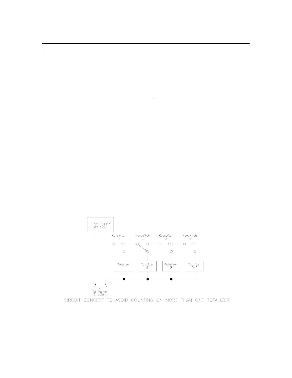
ANTI-MULTI KEY COUNT FEATURE
The keyswitches are wired in series, which ensures the accumulation of counts on only one
counter in the event that a second (or more) key is inser ted while the pump is being operated.
See diagram below. For example, if keyswitch 2 is turned on, all keyswitches after this position
will not function. If, however, while user 2 is pumping fuel and user 1 inserts his key, the pulses
will accumulate on totalizer 1, but not on totalizer 2. Any user will immediately r ealize his error,
since the totalizer will start counting while the user still has his hand on the key.
5 VDC. for 115 or 230 VAC, 50-60HZ.
MANUAL/AUTOMATIC BYPASS SWITCH (AUTO/MAN)
The function of the Electric Keytrol may be bypassed by setting the Auto/Man switch to the
Manual position. This setting allows fueling without using a key and/or without totalizing the fuel
on any counter. It is also used in the event of a failure of any electrical portion of the Keytrol.
03/28/03 2-1
Page 8
GASBOY Electric Keytrol
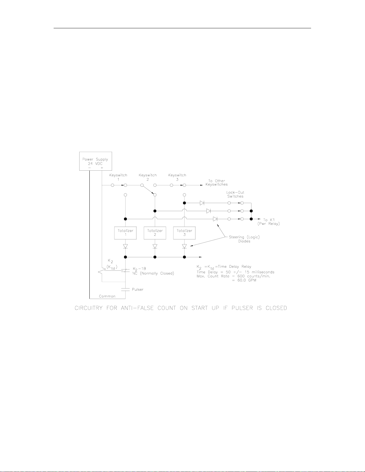
ANTI-FALSE COUNT ON STARTUP
A time delay relay is used to prevent a false count during startup (See figure below). If the pulser
is open, no count occurs upon start-up since the circuit is open. When the pulser is in a closed
position, Relay K2 (the time delay relay) is energized and its contact (K2-1B, which is normally
closed) is open, again preventing a count.
Upon receiving pulses from the pulser, the relay will drop out in 50 milliseconds. The next pulser
closure causes current flow through the normally closed (NC) contact, and actuates the totalizer.
Fifty milliseconds later, while the pulser is still closed, K2 (or Ktd) energizes, its contact opens,
dropping power to the totalizer, thereby reading the fuel in 0.1 gallon increments and not one-half
counts as other devices are prone to do. The 50 millisecond delay of the relay permits a
maximum pumping rate of 60 gpm (227 liters) dispensing and totalizing in 0.1 gallon (or whole
liter) increments.
MISSING PULSE DETECTOR (MPD)
Not available on Split Dual Pump Control Units The Missing Pulse Detector (MPD) circuitry
senses pulses from the pump pulser. If no pulses are received after the key is inserted and turned
in the Electric Keytrol within a preset time, the main power relay will open and an alarm will sound.
The alarm will continue to sound until the key is turned off, whereby the MPD circuitry is reset.
This circuit is primarily designed to prevent dispensing of fuel if the pulser is not functioning
properly. This could be due to a broken cable or shaft linking the pulser to the computer, or a
broken wire from the pulser to the Electric Keytrol.
2-2 03/28/03
Page 9

System Features
The MPD delay is set by applying a slotted screwdriver to the adjuster, K4, located on the relay at
the extreme left of the bottom bracket. It is factory-set to 30 seconds, but can be adjusted to
between 2 to 180 seconds. This same timer also detects the time between pulses, so that a
pulser that malfunctions after fueling has started will also actuate the MPD circuitry. Ever y pulse
resets the timer to zero.
The MPD option also serves as a key reminder alarm. After fueling is complete, and the pulser
stops, the alarm will sound (and power relay open) within the pre-set time (nominally 30 seconds).
This relay may be bypassed by a toggle switch located on the upper left portion of the bottom
bracket.
START DELAY (SD)
Not available on Split Dual Pump Control Units. The GASBOY Electric Keytrol is supplied with an
additional time delay relay that provides a delay on initial turn-on. The delay is adjustable from 3
to 180 seconds. It has been factory set for 3 seconds. Just like the missing Pulse Detector (MPD)
relay, it can be set by the owner to the time desired. See figure below for the location of the
different relays.
Upon actuation of a key, there will be a three second delay before power is applied to the Electric
Reset in the pump or dispenser. Consequently, the register will reset to zero after this delay time
and the fuel can then be dispensed. However, rapid switching of the key will not turn the pump on
and off. It is suggested that the time be set for three seconds to minimize customer
inconvenience. However, to prevent excessive product losses, set the time to ten seconds or
greater.
This relay may be bypassed by a toggle switch located on the upper left portion of the bottom
bracket.
7176 2-3
Page 10

GASBOY Electric Keytrol
LOCKOUT
Individual lockout is provided by means of a 10PST switch mounted at the bottom of each module.
(5PST on 5 counter versions). Access to this portion is accomplished by removing the locked
bezel. The switch can be actuated with the tip of a ball-point pen or any other pointed object. To
reinstate, push the top of the switch lever in firmly. The switch is numbered 1-10 from left to right
on 10 counter modules and 1-5 on 5 counter modules.
ANTI-SURGE DIODES
Diodes D5 and D6 are placed across the time delay relay (K2) and selected totalizer in the reverse
direction. Upon opening of the inductive circuit, the current surges through the diode, minimizing
pulser and K2 relay contact erosion.
HEATER
A heating element controlled by a thermostat set at 40
temperatures fall below the recommended operating temperature. The heater/thermostat circuitry
is continuously connected to the 115 VAC (or 230 VAC) line, but will operate only when the
temperature drops below 40
When an auxiliary unit is used, the 115 VAC or 230 VAC line must be connected from the master
unit for powering the heater, along with the other interconnections.
°F.
°F protects electrical components when
2-4 03/28/03
Page 11

Section 3
INSTALLATION
INSTALLATION PRECAUTIONS
All installations must conform with all building/fire codes, all Federal, State, and Local codes,
National Electrical Code, (NFPA 70), NFPA 30, and Automotive and Marine Service Station Code
(NFPA 30A) codes and regulations. Canadian users must also comply with the Canadian
Electrical Code.
Plan your installation carefully. Dispensing troubles, which seem to be related to the pump or
Electric Keytrol, are frequently traced to the installation. Review the following list of installation
DO’s and DON’T’s to avoid potential problems:
1. DO read the WARNINGS page at the front of this manual, preceding the Table of Contents.
It contains important information regarding the safe use of your dispensing equipment.
2. DO install an emergency power cutoff. In addition to circuit breaker requirements of NFPA
70 and NFPA 30A, a single control which simultaneously removes AC power from all site
dispensing equipment is recommended. This control must be readily accessible, clearly
labeled, and in accordance with all local codes.
In order to provide the highest level of safety to you, your employees, and customers, we
recommend that all employees be trained as to the location and procedure for turning off
power to the entire system.
3. DO have the Electric Keytrol installed by a competent installer/electrician.
4. DO NOT experiment with a pump or Electric Keytrol if you are not sure that the installation is
correct.
5. DO NOT overload sub or main breaker panels.
6. DO NOT use power line wiring of inadequate capacity. (Use gauge specified by the wiring
diagram or wire chart provided in the Wiring section of this manual.)
7. DO NOT use circuit breaker of improper size (See Wiring section of this manual).
8. DO NOT use knock-out boxes or flexible conduit for installing this unit. All wires should be
run in threaded, rigid metal conduit. All threaded connections must be drawn up tight with
five (5) threads minimum engagement. At completion of the installation, it is the installer’s
responsibility to ensure that any unused openings are plugged.
03/28/03 3-1
Page 12

GASBOY Electric Keytrol
GENERAL INSTRUCTIONS
Upon receiving, perform the following:
1. Unpack carefully and report any damage immediately.
2. Using the door key, unlock and open door. (Door opens only 90
this point.)
3. Using the bezel key, remove the bezel by pulling gently outward and down after clearing the
bottom, front of the cabinet. (NOTE: Do not overtighten bezel locks. Tighten lock with key
making 3 to 4 complete turns.)
4. Ensure that all screws holding the modules are in place and tight.
5. Ensure that all terminal block screws are tight.
6. Ensure that no damage has occurred during shipment. Report any damage immediately.
7. Ensure that the time delay relay is properly installed in the upper octal socket (not available
on Split Dual Pump Control units).
CAUTION! Relay and socket are “keyed”, so be careful to align these properly when
reinstalling.
8. Ensure that the missing pulse detector is set for 15 seconds (not available on Split Dual
Pump Control units).
Factory-Mounted Units on a Pump or Dispenser
Follow installation instructions supplied with pump or dispenser.
Field-Mounted Master or Auxiliary Electric Keytrol
IMPORTANT: Do not install in Class 1, Division 1 or Division 2 hazardous location.
1. When mounting on a wall or post, the use of a shelf is recommended; order GASBOY P/N
014632.
2. Auxiliary Keytrol units must be of the appropriate power rating. Units are available for 115
VAC or 230 VAC applications.
3. Install wires in accordance with the National Electrical Code (NF PA 70). Also, all wiring must
conform with local electrical codes. Units must be properly grounded.
4. Seal conduit as per NEC requirements.
°, so do not force it beyond
3-2 03/28/03
Page 13

Section 4
WIRING
☎ Customers and installers having any questions pertaining to the installation should
contact their GASBOY distributor.
WIRING PRECAUTIONS
The quality of the electrical installation is a major factor in maintaining proper safety levels and
providing trouble-free operation of your GASBOY Electric Keytrol and your pump/remote
dispenser. To assure a quality installation, follow these rules:
1. All wiring must be installed to conform with all building/fire codes, all Federal, State, and
Local codes, National Electrical Code, (NFPA 70), NFPA 30, and Automotive and Marine
Service Station Code (NFPA 30A) codes and regulations. Canadian users must also comply
with the Canadian Electrical Code.
2. Use only threaded, rigid, metal conduit.
3. Use only UL-labeled, insulated, gasoline and oil-resistant, stranded copper wiring of the
proper size.
4. Wire connections should be tightly spliced and secured with a wire nut; close off the open end
of the wire nut with electrical tape.
5. The line to the motor should be on a separate circuit and installed on a breaker sufficiently
sized for the motor size and/or the voltage setting.
6. Install an emergency power cutoff. In addition to circuit breaker r equirements of NFPA 70
and NFPA 30A, a single control which simultaneously removes AC power from all site
dispensing equipment is recommended. This control must be readily accessible, clearly
labeled, and in accordance with all local codes.
In order to provide the highest level of safety to you, your employees, and customers, we
recommend that all employees be trained as to the location and procedure for turning off
power to the entire system.
WARNING:
To reduce the risk of electrical shock when servicing, turn off all power to the pump/remote
dispenser. In submersible pump applications, turn off power to the submersible pump and any
other remote dispensers which use that submersible pump. AC power can feed back into a shutoff dispenser when dispensers share a common submersible pump or starter relay.
7. Have the Electric Keytrol and the pump/remote dispenser installed by a competent
installer/electrician.
03/28/03 4-1
Page 14

GASBOY Electric Keytrol
GROUNDING
To ensure proper operation of the equipment and provide the necessary safety factors, this unit
must be grounded. A ground wire (preferably green) must be connected between the ground
terminal position of a remotely-mounted Electric Keytrol, and the main electrical service panel.
When the Keytrol is factory-mounted to a pump or dispenser, the pump or dispenser must be
properly grounded. One (1) earth ground connection is r equir ed per unit. T he ground r od is to be
a solid, corrosion-resistant conductor and must be installed at the main electrical panel in
accordance with the National Electrical Code. It should be properly tied into the ground bus strip
of the panel. We recommend the neutral and ground bus strips be bonded together (unless
prohibited by local codes).
CIRCUIT BREAKERS
Power to the unit should be supplied from a dedicated breaker . No other equipment should be
powered from this breaker. Units directly driving pumps (suction or submersible) should be
supplied power from a separ ate breaker. A tag on the motor identifies the maximum cur rent draw
of the motor. If two (2) pumps are supplied from one breaker, that breaker must be capable of
handling the load of both motors. In cases where multiple remote dispensers supply power to a
single submersible pump, all breakers controlling the remote dispenser must be on the same
phase of power. Failure to do this will damage the equipment. Provisions must be made to break
both legs of any AC circuit.
VOLTAGE REQUIREMENTS
This unit must be supplied with at least 105VAC (210VAC for 230VAC units) to ensure proper
operation. Power should be checked between positions 7 and 8 (H and N or L1 and L2) of the
main terminal block in the Keytrol housing while the pump is idle and running in bypass. If the
power drops below the minimum allowable levels during either of these operation modes, the
Keytrol controls may not function properly.
4-2 03/28/03
Page 15
Wiring
WIRE SIZE
Electric Keytrol - Factory Mounted to Top of Pump or Dispenser
When installing a GASBOY Electric Keytrol, wiring of sufficient size is required. When the Keytrol
is mounted directly to the top of a GASBOY pump or dispenser, the Keytrol is pre-wired to the
dispenser at the factory. Field wiring for this configuration may be referenced by the wiring
diagram for your model pump or dispenser.
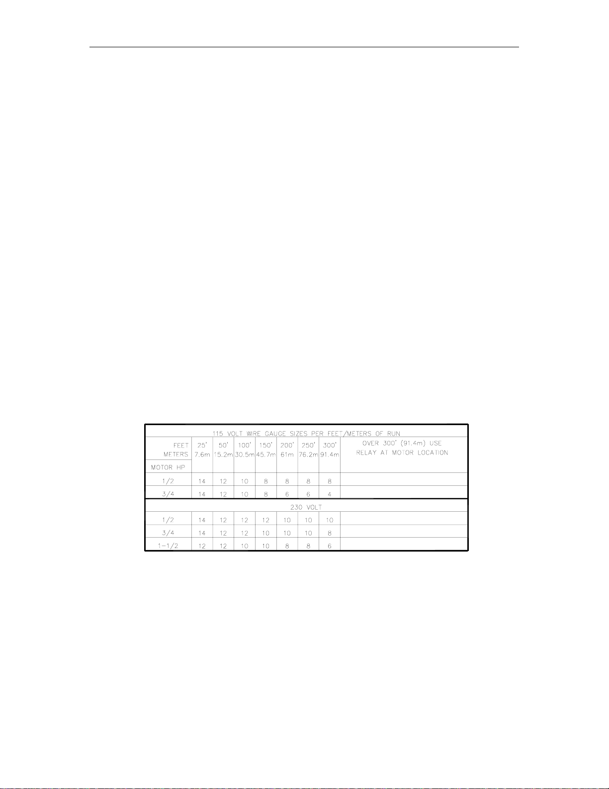
Electric Keytrol - Remotely Mounted from Pump or Dispenser
When the Electric Keytrol is mounted remotely from the dispenser, use the following Wire Size
table as a guide to determine the required sizes for the AC wiring to the master Electric Keytrol
unit. As shown in the table, the wire size is dependent on the HP rating of the pump motor, the
distance from the circuit breaker to the pump/remote dispenser, and the operating voltage ( 115 or
230 VAC) of the circuit.
If multiple units are powered from the same breaker through the same wires, you must increase
the gauge of the wires to handle the added load according to the distance from the breaker panel
and the HP rating (if applicable).
AC wiring from a Master Electric Keytrol unit to an Auxiliary Keytrol unit (Hot, Neutral, and
Ground for 115 VAC, or L1, L2, and Ground for 230 VAC) must be 14 AWG minimum, and sized
according to the breaker feeding the Keytrol. Positions 4 through 7 on an Auxiliary Keytrol unit
(marked A, B, C, and D on the terminal block) handle DC current and should be connected to the
Master Keytrol, or other Auxiliary Keytrol Units, with 18 AWG wiring.
The DC wire size for the Pulser lines must be 18 AWG minimum.
Wire Size
8021 4-3
Page 16

GASBOY Electric Keytrol
CONDUIT
All wiring to the GASBOY Electric Keytrol must be installed in threaded, rigid, metal conduit. PVC
is not acceptable.
All wiring and conduit runs must also conform with the National Electrical Code (NFPA 70) and the
Automotive and Marine Service Station Code (NFPA 30A). All wiring and conduit runs must
conform to local codes. Canadian users must also comply with the Canadian Electrical Code.
Use the charts below as a guideline to determine the proper conduit sizes for a remotely mounted
GASBOY Electric Keytrol. When planning the orientation of the wiring runs, follow the applicable
wiring diagram and consider the layout of the components at the site. Long runs or a large
number of bends may require you to increase conduit size over what is listed.
To determine conduit size needed, use the THHN/THWN Wire Areas table (left) to find the area
for each wire gauge. Add up all wire areas. Use the Areas of Tr ade Size Conduit Table (r ight) to
select the smallest number in the 25% fill area (based on NEC 501-1) that comes closest without
exceeding the total wire area.
WIRING DIAGRAMS
The following schematics show the standard wiring configuration for a GASBOY Electric Keytrol to
a typical dispenser. When connected to a GASBOY Series 9100A pump or dispenser, consult the
appropriate numbered wiring diagram immediately following these standard diagrams. If
connecting to a GASBOY Ser ies 9800A, call GASBOY’s Quick Facts hotline for the appropriate
wiring diagram for your model pump or dispenser. If connecting to an older 9100, 115VAC, or der
packet 024207 for the appropriate wiring diagram; for 230VAC applications contact Gasboy
Technical Service.
1. All wiring must be installed to conform with all building/fire codes, all Federal, State, and
Local codes, National Electrical Code, (NFPA 70), NFPA 30, and Automotive and Marine
Service Station Code (NFPA 30A) codes and regulations. Canadian users must also comply
with the Canadian Electrical Code.
2. Refer to the Wire Size section of this manual to determine the required line sizes.
3. Submersible starter relays are always recommended when a submersible pump is used;
however, the control circuit is capable or directly driving a submersible pump up to 3/4 HP at
115/230VAC. Any pump over 3/4 HP requires a submersible starter relay.
4-4 03/28/03
Page 17

Wiring
8021 4-5
Page 18

GASBOY Electric Keytrol
STANDARD WIRING DIAGRAMS - REMOTE MOUNT
4-6 03/28/03
Page 19

Wiring
STANDARD WIRING DIAGRAMS - SPLIT
8021 4-7
Page 20

GASBOY Electric Keytrol
WIRING DIAGRAM 024267
Models: 9152AX EK, 9153AX EK, 9140AX EK, 7552AX EK, 7553AX EK, 7540AX EK
4-8 03/28/03
Page 21

Wiring
WIRING DIAGRAM 024268
Models: 9152A EK, 9153A EK, 7552A EK, 7553A EK
8021 4-9
Page 22

GASBOY Electric Keytrol
WIRING DIAGRAM 024269
Models: 9153AHC EK, 9140A EK, 7553AHC EK, 7540A EK
4-10 03/28/03
Page 23

Wiring
WIRING DIAGRAM 024270
Models: 9152ATW1 EK M/M, 7552ATW1 EK M/M
8021 4-11
Page 24

GASBOY Electric Keytrol
WIRING DIAGRAM 024271
Models: 9152ATW1 EK SPLIT, 7552ATW1 EK SPLIT
4-12 03/28/03
Page 25

Wiring
WIRING DIAGRAM 024272
Models: 9152ATW2 EK M/M, 9153ATW2 EK M/M, 9153ATW1M EK M/M
7552ATW2 EK M/M, 7553ATW2 EK M/M, 7553ATW1M EK M/M
8021 4-13
Page 26

GASBOY Electric Keytrol
WIRING DIAGRAM 024273
Models: 9152ATW2 EK SPLIT, 9153ATW2 EK SPLIT, 9153ATW1M EK SPLIT
7552ATW2 EK SPLIT, 7553ATW2 EK SPLIT, 7553ATW1M EK SPLIT
4-14 03/28/03
Page 27

Wiring
WIRING DIAGRAM 024274
Models: 9152AXTW1 EK M/M, 9152AXTW2EK M/M, 9153AXTW1 EK M/M, 9153AXTW2 EK M/M,
7552AXTW1 EK M/M, 7552AXTW2EK M/M, 7553AXTW1 EK M/M, 7553AXTW2 EK M/M
8021 4-15
Page 28

GASBOY Electric Keytrol
WIRING DIAGRAM 024275
Models: 9152AXTW1 EK SPLIT, 9152AXTW2EK SPLIT, 9153AXTW1 EK SPLIT, 9153AXTW2 EK SPLIT,
7552AXTW1 EK SPLIT, 7552AXTW2EK SPLIT, 7553AXTW1 EK SPLIT, 7553AXTW2 EK SPLIT
4-16 03/28/03
Page 29

Wiring
WIRING DIAGRAM 024276 (1 OF 2)
Models: 215A/9152AX EK, 215A/9153AX EK, 216A/9140AX EK, 7215A/7552AX EK, 7215A/7553AX EK,
7216A/7540AX EK
8021 4-17
Page 30

GASBOY Electric Keytrol
WIRING DIAGRAM 024276 (2 OF 2)
Models: 215A/9152AX EK, 215A/9153AX EK, 216A/9140AX EK
4-18 03/28/03
Page 31

Section 5
OPERATING SEQUENCE
OPERATING INSTRUCTIONS
1. Insert key in assigned lock, turn 180
2. Remove nozzle from holder.
3. Move start lever down over nozzle holder to reset register to zero and start pump. If your
system is equipped with the Start Delay feature, there may be a delay of several seconds
until delivery begins. Dispense product.
4. After delivery, return start lever to original upright OFF position.
5. Replace nozzle in holder.
6. Turn key off and remove. Close door.
Please notify your fuel or equipment distributor of any malfunction.
MANAGER INSTRUCTIONS FOR BYPASSING ELECTRIC KEYTROL
In case of difficulties, Electric Keytrol may be bypassed as follows:
1. After removing power, open door, insert bezel key and turn clockwise 1/2 turn.
2. Lift up and outward until the bezel clears the bottom of the enclosure. Then, pull downwards
until the bezel is clear. Set the bezel aside on a clean, level surface.
3. Move AUTO/MAN switch down to the MAN or manual position.
4. Replace bezel, being careful not to damage the relay, and turn bezel key 1/2 turn
counterclockwise to remove.
5. Restore power and operate pump manually until the Electrical Keytrol can be serviced.
6. If the pump still will not operate, either the dispenser is at fault or power is off.
°.
03/28/03 5-1
Page 32

Page 33

Section 6
MAINTENANCE AND TROUBLESHOOTING
MAINTENANCE OF YOUR ELECTRIC KEYTROL
Procedures requiring disassembly of portions of the Electric Keytrol, pump, or remote
dispenser must be performed by qualified service personnel.
WARNING:
To reduce the risk of electrical shock when servicing, turn off all power to the
Electric Keytrol, pump/remote dispenser. In submersible pump applications turn
off power to the submersible pump and any other remote dispensers which use
that submersible pump. AC power can feed back into a shut-off remote dispenser
when dispensers share a common submersible pump or starter relay. Always
turn off all power to the r emote dispenser and submerged pumps at the master
panel and close any impact valve before performing any maintenance or service
to the remote dispenser, including the changing of any fuel filters or strainers.
Also block islands so no vehicles can pull up to the remote dispenser when the
dispenser is being worked on.
Demand Competent Service
If your Electric Keytrol should stop or fail to operate properly, don't depend upon the repair service
of a general mechanic unless he is thoroughly familiar with the mechanism. Experience shows
that the repair results will be much more satisfactory if you demand the service of a competent
representative of the pump manufacturer. GASBOY has a distributor network which services fuel
dispensing and management systems in every section of the country.
Use Authorized Parts
Should excessive wear, rust, or corr osion of parts cause inefficient operation, it is always best to
replace them immediately; but if you want the best results and continuity of the Underwriters' Label
on your pump, be sure they are new authorized service parts supplied by GASBOY. Every part of
a pump or remote dispenser is carefully designed for a particular purpose. If it is replaced by an
incorrect or substandard substitute, operation will be unsatisfactory.
Operate with Reasonable Care
Like any machine, an Electric Keytrol that is operated with reasonable care will last longer and
give better service. Abuse should be avoided. The time and care given to your Electric Keytrol
will be returned to you in the form of dependable service.
Preserve the Electric Keytrol Cabinet
Nearly all Electric Keytrol’s are installed outdoors where their surfaces are subjected to the action
of the weather. As a result, it is necessary to give the finish a r easonable amount of care if an
attractive appearance is to be maintained.
03/28/03 6-1
Page 34

GASBOY Electric Keytrol
The finish on GASBOY Electr ic Keytrol is a high-heat baked synthetic enamel, similar to that used
on automobiles. The life of this finish can be lengthened several years if, at regular intervals, the
painted surfaces are thoroughly cleaned with a high grade automobile polish and then protected
with a coat of paste wax. Do not use abrasive cleaners or polish. Do not use high pressure
spraying equipment.
In order to retain the unmarked finish on stainless steel, occasional cleaning is required. In
corrosive atmospheres, such as coastal areas, a more frequent cleaning schedule is necessary.
Under ordinary conditions, washing with detergent or soap and water, followed by a clean water
rinse, is sufficient. If hard water is used, the surface should be wiped dry with a soft clean cloth to
prevent the formation of water spots. Marks or spots, such as grease, oily fingerprints and
smudges which resist soap and detergents, will have to be removed with a stronger cleaner. (DO
NOT use ordinary steel wool as iron particles may adher e to the surface and cause corrosion.)
Care should be taken in choosing a cleaner because any cleaning compounds or powders which
contain abrasives can scratch a mill-rolled finish. Care must be exercised in their use to run in the
direction of the polishing lines in the steel, never across them. After cleaning, an application of
paste wax is recommended to protect the surface and prolong the interval between cleaning.
TROUBLESHOOTING
The paragraphs that follow detail troubleshooting procedures for major components in your
Electric Keytrol.
ANTI-FALSE COUNT RELAY, P/N 0M0017
1. To check for faulty relay, r emove relay and short pin 6 to 7. Operate dispenser. If counter
operates, the time delay relay is faulty. Replace with a new unit.
2. The dispenser and Electric Keytrol can be operated indefinitely this way, only the unit may
pick up a count (0.1 gallon) on start-up if the pulser has stopped in a closed position.
POWER RELAY, P/N 0M0015
1. Check power relay for movement of the armature when a key is inserted and turned.
2. If the armature moves in, but the pump will not run, move bypass switch to MANUAL. If the
pump starts, the trouble is in the power relay contacts. Replace power relay or clean
contacts.
3. If the armature does not move in, check for voltage across the coil when a key is inserted and
turned. Proper voltage should be 24 VDC +
coil is burned out. Replace power relay.
4. If voltage is not pr esent across the coil when a key is inserted and turned, the trouble lies
elsewhere. Check power supply and counter module.
5. To replace power relay, r emove counter modules and bottom br acket. Care fully remove both
through bolts ensuring that no parts (spacers, nuts, washers) are lost. Replace relay,
ensuring that the spacers are properly installed, otherwise the bottom of the printed circuit
board (PCB) will short to the chassis. Reinstall wires to proper terminals, one at a time to
prevent mix-ups.
6. Replace bottom bracket and counter modules and check for proper operation.
5 VDC. If this voltage is present, then the relay
6-2 03/28/03
Page 35

Maintenance and Troubleshooting
POWER SUPPLY TRANSFORMER
For 115 VAC Units, P/N 0M0008
1. The output of the power transformer should be 24 VAC (50- 60 Hz) +
5 VAC for 115 VAC line.
If no voltage is present, check on primary side for 115 VAC. If 115 VAC is present at the
primary, but no voltage appears at the secondary, the transformer is defective. Replace
transformer.
2. To replace transformer, remove all counter modules and bottom bracket. Remove bolts and
cut wires after marking or identifying leads.
3. Strip and splice leads with solder and tape properly.
4. Remount with the two bolts.
5. Reinstall bottom bracket and counter modules.
6. Check for proper operation.
For 230 VAC Units, P/N 0M0055
1. The output of the power transformer should be 24 VAC (50- 60 Hz) +
5 VAC for 230 VAC line.
If no voltage is present, check on primary side for 230 VAC. If 230 VAC is present at the
primary, but no voltage appears at the secondary, the transformer is defective. Replace
transformer.
2. To replace transformer, remove all counter modules and bottom bracket. Remove bolts and
cut wires after marking or identifying leads.
3. Strip and splice leads with solder and tape properly.
4. Remount with the two bolts.
5. Reinstall bottom bracket and counter modules.
6. Check for proper operation.
COUNTER OR TOTALIZER, P/N 0M0010
1. If any one counter does not function properly, when all other counters on that same module
strip do, then the trouble is in the counter or keyswitch. To eliminate the keyswitch as the
source of error, jumper from the top turret ter minal (with a red lead C 24 VDC) to the proper
turret terminal of the counter under question (white lead) and operate pulser. If the counter
functions, replace keyswitch. If keyswitch is not defective, replace counter.
2. Counter removal. (Record reading for inventory).
l
Remove 4 bolts holding printed circuit board (PCB) to frame.
l
Remove two bolts holding the counter to the PCB and carefully swing PCB with counters
away from frame. CAUTION! The two counter bolts are metric threads. Do not lose
or replace with standard screws.
l
Unsolder the two leads from the turret terminals.
03/28/03 6-3
Page 36

GASBOY Electric Keytrol
l
Mount new counter with the same two bolts or bolts provided with the new counter.
Counters are 24 VDC (Record reading).
l
Solder leads to same turret terminals from which the old counter was removed.
l
Re-bolt PCB with four bolts.
3. If all the counters on one module strip do not function, while those on another adjacent
module do, check all four spade terminal connections for breakage or loose terminal block
screws.
4. If none of the counters ar e functioning, the problem may be with the pulser, 24 VDC power
supply or interwiring.
KEYSWITCH (Microswitch: P/N 0M0011, includes tumbler)
1. Keyswitches can be isolated as the source of error as described in section Counter or
Totalizer.
2. If the keyswitch turns (physically) but does not actuate the rear-mounted microswitch, as
determined above, it is not necessary to remove the tumbler mechanism from the frame.
Also, it may be desirable to leave the same tumbler mechanism to avoid having to issue new
keys.
3. To remove the rear-mounted microswitch, remove PCB as described in Counter or
Totalizer, Step 2. Unscrew 2 bolts holding the microswitch to the rear of the key mechanism.
CAUTION! DO NOT LOSE THESE SCREWS!
4. Mark lead orientation and unsolder, or pull off.
5. Solder new leads in same configuration as removed, or push on.
6. Rebolt microswitch.
7. Rebolt PCB.
KEYSWITCH (Tumbler: P/N 0M0011, includes microswitch)
1. To change lock mechanism it is not necessary to remove or unsolder the microswitch.
2. Remove 2 bolts holding microswitch to rear of key mechanism.
3. Remove nut holding switch tumbler to frame. Remove tumbler mechanism.
4. Install new key lock tumbler and tighten nut.
5. Rebolt microswitch.
6. Rebolt PCB.
7. Issue new key(s) to proper personnel.
6-4 03/28/03
Page 37

Maintenance and Troubleshooting
ADDING MODULES IN THE FIELD
Modular construction allows ease in adding strips of counters in units of 5 or 10. To install, first
turn off all power to the Electric Keytrol and pump. Then remove the locked bezel. Remove a
blank panel (held with two screws). Loosen the four appropriate term inal block screws, removing
the jumper between terminals C and D. Carefully install the counter module with its spade
terminals behind the lower support bar and into the terminal block. Make certain all 4 terminals on
the module are behind the screw heads of the terminal block. Reinstall and tighten the two screws
holding the module first. Then, tighten the four terminal block screws. Check the position of the
lockout switches to ensure that the desired units are on. Check each counter for operation.
Record the starting number. Reinstall bezel.
PULSER INSTALLATION ON EXISTING REGISTERS
Electric Keytrol’s may be retrofitted to an existing dispensing system, which requires installation of
a pulser. The pulser must be installed so that an active keyswitch will not recor d pulses during a
reset cycle. To accommodate this restriction, the pulser should drive off the center extended
shaft, which does not turn during the reset cycle. Another method is to wire one leg of the pulser
through an isolated, normally open switch in the electric reset or control handle switch housing
which will then close when the motor or solenoid valve is activated after reset is complete. This
method allows the pulser to be driven by the gallon wheel which turns during the reset cycle.
03/28/03 6-5
Page 38

Page 39

Section 7
PARTS
USING THIS PARTS LIST
This section lists parts information for the Electrical Keytrol Unit for pumps and dispensers. Using
part numbers when ordering will expedite your order and reduce the possibility of the wrong parts
being shipped. When ordering replacement parts, be sure to give the complete name and part
number as shown in the appropriate parts list. It is also helpful to supply the serial number of the
equipment.
Procedures requiring disassembly of portions of the unit should be performed by competent
service personnel. Do not depend upon the repair service of a general mechanic unless he is
thoroughly familiar with the mechanism. GASBOY has a distributor network which services fuel
dispensing equipment and management systems in every section of the country.
WARNING:
To reduce the risk of electrical shock when servicing, turn off and lock out all power to the
pump/dispenser. In submersible pump applications, turn off and lock out power to the
submersible pump and any other pumps/dispensers which use that submersible pump. AC power
can feed back into a shut-off dispenser when dispensers share a common submersible pump or
starter relay. Always turn off and lock out all power to the dispenser and the submer sible pump at
the master panel and close any impact valve before performing maintenance or service to the
dispenser, including the changing of any fuel filters or strainers. Also block islands so no vehicles
can pull up to the dispenser when the dispenser is being worked on.
03/28/03 7-1
Page 40

GASBOY Electric Keytrol
7-2 03/28/03
Page 41

Parts
ELECTRICAL KEYTROL ASSEMBLY
Item Part No. Description Qty.
1 017318 Cabinet, EK50, CRS - Must replace Assembly (Specify color) 1
017302 Cabinet, EK50, SS - Must replace Assembly 1
017321 Cabinet, EK50, CRS w/ Auxiliary (Specify color) 1
017349 Cabinet, EK50, SS w/ Auxiliary 1
(Includes Items 2-6, not sold separately)
2 Latch Catch 1
3 Spring Bracket 1
4 Hinge, Righthand Female 4
5 Bottom Bracket Locating Stud 2
6 Bottom Support Bar 1
Top Support Bar (Not Shown) 1
7 057445 Door Spring 1
8 054475 Shaft 1
9 067270 Washer 1
10 049391 Retaining Ring 2
11 017341 Cabinet Cover Assembly, CRS (Specify color) 1
017342 Cabinet Cover Assembly, SS 1
Must replace Assembly (Includes Items 4, 12-18,
not sold separately)
12 Cabinet Cover 1
13 Door Spring Guide Bracket 1
14 Weld Bolt 4
15 Gasket Clamp 4
16 Keps Nut, 6-32 4
17 Gasket, 3/8 x 3/4 x 17-1/2 2
18 Gasket, 3/8 x 3/4 x 15-1/2 2
19 029415 Lock Handle (Not Shown) 1
20 Lockwasher (Part of Item 19) 2
21 Hex Nut, 1/4" (Part of Item 19) 2
22 068281 Spring Washer 1
23 017607 Cam 1
24 068710 Washer 1
25 042310 Cotter Pin 1
26 0M0020 Counter Module, 10 Key, White 1-5
0M0033 Counter Module, 5 Key, White 1-5
0M0622 Counter Module, 10 Key, whole liter, White 1-5
27 026503 Panel, Blank As Req'd
28 053019 Screw, 10-32 x 1/2 10
29 0M0377 Bottom Bracket Assembly 1
0M0376 Bottom Bracket Assembly, A/T
0M0111 Bottom Bracket Assembly, Dual Control
0M0448 Bottom Bracket Assembly, 230 VAC
0M0447 Bottom Bracket Assembly, 230 VAC A/T
0M0635 Bottom Bracket Assembly, 230 VAC, Dual Control
30 039069 Keps Nut, 6-32 1
31 012365 Bezel, (A-E), White 1
012366 Bezel, (F-J), White 1
32 035026 Bezel Lock (master/aux; must purchase 2 locks) 2
035027 Bezel Lock (master/aux, master/master,
must purchase 4 locks) 4
NOTE: Individual locks not availab le.
33 039460 Speed Nut 2
34 051805 Screw, 1/4-20 x 5/8 HHC 4
35 068281 Lockwasher 4
36 068005 Washer 4
37 029983 Hinge Pin 1
38 049390 Retaining Ring 2
39 012268 Bezel Locking Bar 1
Mounting Hardware (Not Shown)
003101 Base Casting, Flat, 9100 Series 1
003073 Base Casting, Curved, 50 Series 1
062102 Standoff 4
014632 Shelf, for wall or post mount 1
013631 U-Bolt 2
03/28/03 7-3
Page 42

GASBOY Electric Keytrol
7-4 03/28/03
Page 43

Parts
BOTTOM BRACKET ASSEMBLY
Item Part No. Description Qty.
1 014897 Bottom Bracket (0M0377 & 0M0448) 1
014899 Bottom Bracket (0M0376 & 0M0447) 1
014901 Bottom Bracket (0M0108) 1
2 0M0065 Relay, MPD-TD 2
3 0M0008 Transformer, 115/24V 1
0M0055 Transformer, 230/24V 1
4 0M0015 Power Relay 1
5 0M0017 Relay, Anti-False Count 1
6 0M0067 Accumulative Totalizer 1
7 039069 Keps Nut, 6-32) 13
8 0M0006 Octal Socket 2
9 052689 Screw, 6-32 x 3/8 9
10 Locknut, (Part of 11) 2
11 064455 Toggle Switch - Start Delay 2
12 Bushing (Part of 11) 2
13 0M0045 Auto-Manual Label 1
14 0M0068 Nylon Bushing 5
15 0M0124 Printed Circuit, MPD Assembly 1
(Must Replace Assembly)
16 039070 Keps Nut, 8-32 14
17 067126 Washer, #8 3
18 052706 Screw, 8-32 x 7/8 Pan Hd Phl 13
19 052751 Screw, 8-32 x 1-1/4 1
20 0M0022 Marker Label (115 V) 1
0M0201 Marker Label (230 V) 1
21 0M0016 Terminal Block 1
22 0M0007 Terminal Block 2
23 0M0041 Terminal Block 1
24 0M0044 A, B, C, D Label 5
25 011303 Totalizer Mounting Bar 1
26 025010 Heater, 115 VAC 1
025018 Heater, 230 VAC 1
27 Z09835 Cable Clip 1
28 Z10187 Thermostat, 115 VAC 1
C01449 Thermostat, 230 VAC 1
30 062101 Spacer 7
31 0M0370 Switch, DPDT Toggle, MPD 1
32 Lock Nut (Part of Item 31) 1
33 Bushing (Part of Item 31) 1
34 0M0275 Relay Shield 1
35 062104 Standoff, 1/4 dia. x 1-3/8 lg. 2
36 052870 Screw, 8-32 x 1/2 4
37 068152 Lockwasher 4
38 0M0502 Terminal Block Cover (Not Shown) 1
0M0047 Jumper (Not Shown) As req'd
03/28/03 7-5
Page 44

GASBOY Electric Keytrol
7-6 03/28/03
Page 45

Parts
COUNTER MODULE ASSEMBLY
Item Part No. Description Qty.
0M0020 Counter Module Assembly (10 Key) 1-5
0M0033 Counter Module (5 Key) 1-5
0M0622 Counter Module (10 Key, Whole Liter) 1-5
0M0071 Counter Module (5 Key, Whole Liter) 1-5
All Assemblies include Items 1 through 15
1 099400 Key, Reg #, each keyswitch 2
Specify letter number location, (i.e., A1) or
number of key or lock (i.e., WMExxxx)
2 0M0011 Keyswitch 5-10
0M0293 Switch only (subpart of 0M0011) 1
3 026502 Counter Module Frame 1
4 Hex Nut (Part of Item 2) 5-10
5 057055 Bushing 5-10
6 028767 Cover Glass 1
7 052689 Screw, 6-32 x 3/8 4
8 062100 Standoff 4
9 0M0010 Counter 5-10
0M0105 Counter, Whole Liter 5-10
10 Screw (Part of Item 9) 10-20
11 0M0024 Printed Circuit Board 1
12 049616 Rivet 4
13 0M0013 Spade Terminal 4
14 0M0014 Rocker Switch Assembly, 10 pole, single throw 1
03/28/03 7-7
Page 46

GASBOY Electric Keytrol
7-8 03/28/03
Page 47

Parts
BOTTOM BRACKET ASSEMBLY FOR DUAL PUMP CONTROL
Item Part No. Description Qty.
014909 Bottom Bracket (0M0111 & 0M0635) 1
1 0M0018 Diode PCB Assembly 1
2 062101 Spacer, Aluminum #8 x 1/2" Lg. 2
3 025010 Heater, 60W, 115 VAC 1
025018 Heater Strip, 60W, 230 VAC 1
4 0M0068 Bushing, Snap-in, 1/4" ID 6
5 Z10187 Thermostat, 15A, 55F-0/40F, 115 VAC 1
C01449 Thermostat, Close 50F/Open 65F-22, 230 VAC 1
6 068152 Lockwasher, #8 Int Tooth 4
7 052854 Screw, 8-32 x .375 RH 2
8 039070 Nut, Hex Keps, 8-32 16
9 062104 Standoff, 1/4" x 1.375 Lg. 4
10 0M0275 Relay Shield, EK 2
11 0M0367 Terminal Block, Machined 1
12 0M0007 Terminal Block, 12-position, .437 ctrs, 1 row, 20 A 2
13 0M0044 A, B, C, D Label, EK 5
14 064455 Toggle Switch, 12 V 2
15 0M0045 Auto-Man Label 2
16 0M0016 Terminal Block, 9-pos, .562 ctrs, 2 row, 30A 1
17 052706 Screw, 8-32 x 7/8 Pan Hd, Phl 14
18 0M0015 Power Relay, SPST-N.O., 24 VDC 2
19 052751 Screw, 8-32 x 1-1/4 Fillstr Hd 2
20 0M0008 Transformer, 115V/24V 1
0M0055 Transformer, 230V/24V 1
21 0M0006 Octal Socket 2
22 0M0017 Relay, T/D Octal, 24 VDC 2
23 0M0502 Terminal Block Cover, Silkscreened (Not Shown) 1
03/28/03 7-9
Page 48

GW01 - 6/04/02 Rev. 1
WARRANTY
General Statements:
Gasboy International LLC. warrants all new equipment manufactured by Gasboy against defective material and/or workmanship, for the warranty
period specified below, when the equipment i s installed in accordance with specifications prepared by Gasboy.
This warranty does not cover damage caused by acci dent, abuse, Acts of God, lack of s urveillanc e of automatic recording systems , negl i gence,
mis-application, faulty installation, improper or unauthorized maintenance, installation or use in viol ation of product manuals, instructions, or warnings.
Under no circumstanc e shall Gasboy be liable for any indirect, special , or consequential damages, losses , or expenses to include, but not limited
to, loss of product, los s of profits, litigation fees, or the use, or inabilit y t o use, our product for any for any purpose whatsoever.
Parts Only - During the warranty period, Gasboy will, at its option, repair or replace def ective parts returned transportation prepaid to its factory.
On-Site Labor Included - Gasboy will also provide, within the Continental United St ates and during the warranty period, the services of an
Authorized Service Representati ve (A SR) for on-site repair or replacement of defective parts.
Replacement Parts - Any system components that are not part of the original system order, incl udi ng I sland Card Readers, Pump Control Units, et c.,
are considered replacement part s.
Equipment Term Coverage
Commercial Pumps and Dispensers
Full-Cabinet Consumer Pumps
Small Transfer Pumps, Meters,
Pressure Regulators
Keytrol One year from date of installation or 18 mos . from date of
Fuel Management Systems :
- CFN/ Profit Point
- Series 1000/Fleetkey
- TopKAT
- Fuel Point Readers
(sold with new systems)
Additional Fuel Point Items:
- Fuel Point Readers sold for
retrofitting existing sys t ems.
- Fuel Point vehicle and dispenser
components.
Encoders, Embos sers, Modems,
CRTs, and Logger Printers
Air Diaphragm Pumps Three years from date of purchas e (for full warranty
Items not m anufactured by Gasboy
(ex. automatic nozzles, hoses, swivels,
etc.)
Replacement Parts One year from date of Gasboy International's invoice to the
To the extent permitted by law, this warranty is made in lieu of all other warranties, expressed or impl i ed, including warranties of freedom from pat ent
infringement, or merchant ability, or fitness for a particular purpose, or arising from a course of dealing or usage of trade. No one is authorized to
vary the terms of the warranty nor may anyone make any warranty of representation, or assume any liability other than that herei n stated, in
connection with the sale described herein. The acceptance of any order by Gasboy International i s expressly made subject to the purchaser' s
agreement to these condit i ons.
One year from date of instal l at i on or 18 mos. from date of
Gasboy International’s invoi ce to the purchaser, whichever
comes first.
One year from date of instal l at i on or 18 mos. from date of
Gasboy International’s invoi ce to the purchaser, whichever
comes first.- Excepting the Model 2020 Hand Pump, which
has a 90-day warranty from date of GASB OY International’s
invoice.
Gasboy International’s invoi ce to the purchaser, whichever
comes first.
One year from date of start-up or 15 mos. from date of
Gasboy International’s invoi ce to the purchaser, whichever
comes first .- The basic warranty only applies to systems
which have been started up by a Gasboy Authorized Servi ce
Representative (ASR).
One year from date of start-up or 15 mos. from date of
Gasboy International’s invoi ce to the purchaser,
whichever comes first.
Purchased with Fuel Management Syst em (Encoders,
Embossers only):
90 days from the date of s tart-up by a Gasboy ASR, or 180
days from date of Gasboy I nternational's invoice, whichever
occurs first.
Purchased with Fuel Management System
(Modems, CRTs, and Logger Printers only):
Matches system warranty.
Purchased Separately:
90 days from date of Gasboy I nt ernational's
invoice to the purchaser.
description, see Price List).
Not warranted by Gasboy International (consul t original
manufacturer’s warranty).
purchaser.
Parts and Labor.
Parts Only.
Parts and Labor.
Parts and Labor.
Parts Only.
Purchased with System
(Encoders, Embos sers only):
Parts only.
Purchased with System (Modems,
CRTs, Logger Printers only):
Matches system warranty.
Purchased Separately:
Parts Only.
Parts Only.
Not Applicable.
Parts Only.
GASBOY INTERNATIONAL LLC
P.O. Box 309, Lansdale, PA 19446 ● (800) 444-5579 ● FAX: (800) 444-5569 ● www.gasboy.com
 Loading...