

Garz & Fricke CUPID core, CUPID 5.7 basic, CUPID 5.7 open frame, CUPID 5.7 boxed, CUPID 7.0 basic User Manual
...
CUPID SERIES · Manual
For PCB revision 0.7 or Pre-Release for HW 1.1 or later

CUPID SERIES · Manual
1 Important hints
Thank you very much for purchasing a Garz & Fricke product. Our products are dedicated to professional use
and therefore we suppose extended technical knowledge and practice in working with such products.
The information in this manual is subject to technical changes, particularly as a result of continuous
product upgrades. Thus this manual only reflects the technical status of the products at the time of
printing. Before design-in the device into your or your customer’s product, please verify that this
document and the therein described specification is the latest revision and matches to the PCB
version. We highly recommend contacting our technical sales team prior to any activity of that kind.
The attached documentation does not entail any guarantee on the part of Garz & Fricke GmbH with
respect to technical processes described in the manual or any product characteristics set out in the
manual. We do not accept any liability for any printing errors or other inaccuracies in the manual
unless it can be proven that we are aware of such errors or inaccuracies or that we are unaware of
these as a result of gross negligence and Garz & Fricke has failed to eliminate these errors or
inaccuracies for this reason.
Garz & Fricke GmbH expressly informs that this manual only contains a general description of
technical processes and instructions which may not be applicable in every individual case. In cases of
doubt, please contact our technical sales team.
In no event, Garz & Fricke is liable for any direct, indirect, special, incidental or consequential
damages arising out of use or resulting from non-compliancy of therein conditions and precautions,
even if ad vised of the po s sibi lit y of such dama ge s.
Before using a device covered by thi s document, please carefully read the
Warranty hints in Annex A,
Application notes in An nex B and finally the
Saf ety in structi ons in Annex C
at the end of the document and the important hints outlined on this page.
Embedded systems are complex and sensitive electronic products. Please act carefully and ensure
that only qualified personnel will handle and use the device at the stage of development. In the event
of damage to the device caused by failure to observe the hints in this manual and on the device
(especially the safety instructions), Garz & Fricke shall not be required to honour the warranty even
during the warranty period and shall be exempted from the statutory accident liability obligation.
Attempting to repair or modify the product also voids all warranty claims
Before contacting the Garz & Fricke support team, please try to help yourself by the means of this
manual or any other documentation provided by Garz & Fricke or the related websites.
If this does not help at all, please feel free to contact us or our partners as listed below.
Our technici ans an d engine e rs will be g lad to suppor t you. Pl ea se n ot e th at be yo nd the su pp or t hou rs
included in the Starter Kit, various support packages are available. To keep the pure product cost at a
reasonable level, we have to charge support and consulting services per effort.
Shi ppi ng address:
Garz & Fricke GmbH
Te mpow er krin g 2
21079 Hamburg
Germany
Support contact:
Phone +49 (0) 40 / 791 899 - 30
Fax +49 (0) 40 / 791 899 – 39
Email f support@garz-fricke.com
URL f www.garz-fricke.com
© Copyright 2011 by Garz & Fricke GmbH. All rights are reserved.
Copies of all or part of this manual or translations into a different language may only be made with the
prior written approval.
2

CUPID SERIES · Manual
3
Content
1
Important hints 2
2 Introduction 4
2.1 Type plate and device information 4
2.2 Related documents and online support 4
3 Product description 5
3.1 Boxed design 5
3.2 Open frame design 6
3.3 Technical data (options are greyed out) 7
3.4 Mechanical properties 8
3.5 BIOS and operation systems 8
3.6 Internal battery 9
3.7 PCB design and connectors 10
4 Pin assignment and description 11
4.1 Ethernet/PoE (X24) 11
4.2 Power (X1) 11
4.3 Speaker (X9/X10) 11
4.4 USB - Host (X34) 11
4.5 USB - OTG (X20) 11
4.6 RS-232/MDB (X13) 12
4.7 CAN/RS-485 Interface (X39) 13
4.8 Digital I/O (X14) 14
4.9 Keypad/SPI (X21) 15
4.10 Internal Audio (X8) 16
4.11 Suppliers and sources 17
5 Product geometry 18
5.1 CUPID 5.7 open frame 18
5.2 CUPID 7.0 open frame 19
5.3 CUPID 5.7 boxed 20
5.4 CUPID 7.0 boxed 21
Annex A: Warranty hints 22
Annex B: Application notes 23
Annex C: Safety instructions 24
Annex D: EMC – Declaration of electromagnetic conformity 25
Annex E: Trademarks and service marks 26
Annex F: Document revision history 27

CUPID SERIES · Manual
2 Introduction
This document is valid for hardware revisions 1.1 or later of the CUPID SERIES and thereon based
customized variants:
CUPID Product Name
Order Codes Article Number
Starter Kit Product Rev. 1.1 Rev. 1.2
CUPID core - 10156 - 900-2041R
CUPID 5.7 basic - - NA NA
CUPID 5.7 open frame 10132 10130 900-1952R 900-2050R
CUPID 5.7 boxed 10133 10131 900-1953R 900-2051R
CUPID 7.0 basic - - NA NA
CUPID 7.0 open frame 10125 10117 900-1948R 900-2048R
CUPID 7.0 boxed 10126 10118 900-1949R 900-2049R
For hardware version prior 1.1, please refer to the manual GF_CUPID_Series_Manual_V1.0.3.pdf
on our FTP server.
2.1 Type plate and device information
For service and later identification of the device, the type plate contains important information, such as article
numbers (linked to the PCB rev.), the order code and model name (which is valid for all PCB rev.) and the
serial number, that identifies the exact device.
Article number
Order code
Model name
Serial number
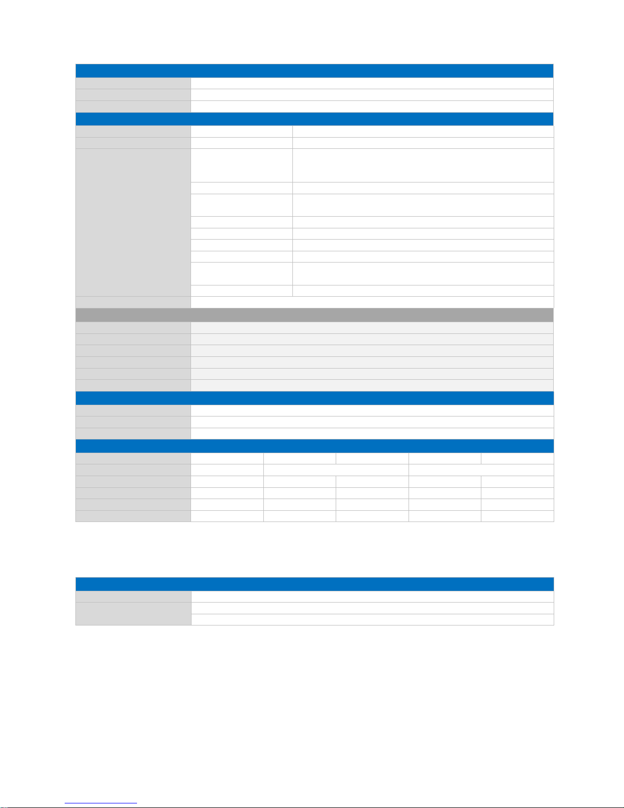
2.2 Related documents and online support
This document contains product specific information. Additional documentation is available for the use of
embedded operating systems and the related tool chain and the RedBoot BIOS.
Title File Name
Description
RedBoot User Manual GF_RedBoot_User_Manual_Rnn.pdf Contains relevant information about BIOS,
boot logo, display settings, etc.
Windows OS Manual GF_WindowsCE_Manual_Vn.n.pdf Contains information about Windows
Embedded CE, the tool chain, the
development environment Visual Studio,
Garz & Fricke tools, etc.
Linux OS Manual GF_Linux_Manual_Vn.n.pdf Contains information about Linux BSP, the
tool chain, Qt, etc.
Support for your Garz & Fricke embedded device is available on the Garz & Fricke website. You may find a list
of the documents available, as well as their latest revision and updates for your system:
Product Link to Garz & Fricke website
CUPID SERIES f http://www.garz-fricke.com/cupid-download
4

CUPID SERIES · Manual
3 Product description
CUPID is an Embedded System used as human machine interface (HMI) in various applications. Please refer
to f Annex B: Application notes for further information. The system is equipped with a large number of
industrial interfaces. A wide variety of options is available as well.
3.1 Boxed design
The following illustration shows the boxed version with 7” display and is meant for your orientation.
For drawings, please refer to chapter f 5 Product geometry.
Aluminium frame
Front cover
Resistive touch
Reset switch
SD-card slot
Power LED
Connectors and interfaces
Back cover
4x installation brackets
Rubber fitting
Fixation for internal Speaker
Ground tags for
Power/Digital/IO/CAN/RS485/RS232
Version with 5.7” display
5

CUPID SERIES · Manual
3.2 Open frame design
The following illustration shows the open frame version with 7” display and is meant for your orientation.
For drawings, please refer to chapter f 5 Product geometry.
Installation frame
Display with resistive touch
Reset switch
SD-card slot
Power LED
Connectors and interfaces
Back cover
Fixation for internal Speaker
Ground tags for
Power/Digital/IO/CAN/RS485/RS232
Version with 5.7” display
6

CUPID SERIES · Manual
7
3.3 Technical data (options are greyed out)
CPU
Type Freescale ARM1136JF-STM i.MX35
Clock/Frequency 532 MHz
Specifications 32 bit with MMU
16 KB L1 I-Cache and D-Cache
128 KB L2 Cache
Memory
ROM 256 MB NAND-Flash
RAM 128 MB DDR-SDRAM / 512 KB SRAM
Storage Card Slot 4 bit MMC/SDIO/SD/SDHC up to 4 GB
Graphics
Controller Programmable LCD controller
Resolution Up to 800 x 600 pixel
Colours 16 bit (65,536 colours)
Supported Orientation Horizontal/vertical
LCD Display and Resistive Touch1
Size (inch / mm) 5.7 / 144 7.0 / 178
Width x Height (pixels) 640 x 480 (VGA) 800 x 480 (WVGA)
Colours 262,144
Backlight Unit LED
Luminance 400 cd/m²
Active Area W x H (mm) 115.2 x 86.4 152.4 x 91.44
Viewing Direction 12 o’clock
Viewing Angle (Typ.) 100° (V) / 140° (H) 120° (V) / 140° (H)
Lifetime Backlight 20,000 h 30,000 h
Touch 1,000,000 (finger) touches
Surface Properties Anti-glare
Hardness 3H
Touch Technology Standard 4 wire resistive analogue
PCT Option Type Single Touch
Transmissivity 90 %
Controller position On FPC
Interface Internal I²C
Interfaces
Network 1x 10/100 Mbit/s Ethernet (RJ45)
Audio 16-bit 48 kHz, 1x1 Watt RMS (8)
Serial Interfaces 2x RS-232 (RX/TX/CTS/RTS)
1x RS-485, galv. isolated together with CAN
MDB Option 1x MDB instead of 2
n
d
RS-232
USB 2.0 1x 12 Mbit/s Full-Speed Host (Type A)
1x 480 Mbit/s High-Speed OTG (Type Micro-AB)
Max. output 500 mA
CAN Fieldbus 1x CAN (ISO/DIS 119898), galv. isolated together with RS-485
CAN2 Option 2nd CAN instead of RS-485
Keypad/SPI/I²C Standard
Multiplex mode 1
Multiplex mode 2
Multiplex mode 3
1x 8x8
1x 5x5 Keypad, 1x SPI
1x 7x7 Keypad, 1x I²C
1x 4x4 Keypad, 1x I²C, 1x SPI
Speaker Speaker Option 1x 300 mW (max. 600 mW) RMS (8)
on internal connector X9
Power Supply and Consumption
Supply Nom. 12/24 V DC or PoE (Power over Ethernet)
Consumption t.b.d. t.b.d.
t.b.d. t.b.d.
t.b.d. t.b.d.
Internal Backup Battery
(RTC)
Type 3 V Li-Ion Type CR2032
Lifetime >10 years, depending on application
1
Display specification may vary due to customization. For further questions, please contact technical support.
CUPID SERIES · Manual
8
3.4 Mechanical properties
Housing
Metal parts 1.4016 high quality steel
Thickness 0.75 mm
Surface treatment Polished
Front (boxed versions only)
Frame Material 4 mm AlMg3
Surface treatment Natural anodized, E6/EV1
Décor cover Material Polyester film with antiglare coating
4C silk screen printing from behind
Structured front coating
Thickness 180 µ
Chemical Resistance Resistant to alcohols, dilute acids, dilute alkalis, esters,
hydrocarbons, ketones, household cleaning agents
Dielectric strength 125 µ: 125 kV/mm (15.6 kV) / 175 µ: 105 kV/mm (18.4 kV)
Surface resistivity > 1013 /sq 500 Vd.c
Switch life > 5 million flexes
Pencil hardness 3H
Maximum long term
use temperature
@ low humidity (<10% RH): 85° C
@ high humidity (10 ~ 95% RH): 60° C
Min. use temperature -40° C
Protection Class IP64 (according to supplier’s statement, not yet approved)
Projective Capacitive Touch (Option)
Surface treatment Surface is scratch and impact resistant.
Chemical Resistance Top surface glass is chemical resistant with no wear from normal use
Thickness 2.25 mm
Weight 93 g
Storage Temperature -20° ~ +70° C
Operating Temperature -30° ~ +80° C
Environmental Conditions
Storage Temperature -20° ~ +70° C
Operating Temperature 0° ~ +60° C
Relative Humidity 95% (non condensating)
Dimensions
CUPID Type/Display size - 5.7 7.0 5.7 7.0
Model core open frame boxed
Width (mm) 138.0 155.5 183.5 165.5 202.0
Height (mm) ca.17.0 98.6 104.0 120.0 126.2
Depth (mm) ca. 80.0 29.5 27.0 29.5 29.5
Weight 220 g 420 g 480 g 520 g 610 g
For drawings, please refer to chapter f 5 Product geometry.
3.5 BIOS and operation systems
Software
BIOS RedBoot BIOS
Operating System Windows Embedded CE 6.0
Linux
For more software information, please refer to f 2.2 Related documents and online support.

CUPID SERIES · Manual
3.6 Internal battery
The internal baseboard is equipped with a Lithium battery (CMOS battery, type CR2032), which has a typical
lifetime longer than 10 years.
Danger of explosion when replaced with wrong type of battery.
Replace the battery only with a Lithium battery that has the same or equivalent type recommended
by Garz & Fricke GmbH.
Do not dispose of used CMOS batteries in domestic waste.
Dispose of the battery according to the local regulations dealing with the disposal of these special
materials (e. g. to the collecting points for disposal of batteries).
3.6.1 Replacement of the internal battery
The internal battery is placed as per figure below.
For replacement, the SD-card and the back cover have to be removed.
The device shall be opened by authorized and skilled personnel only.
Danger of electric hazard! First before opening, please make sure that the unit is completely
disconnected from any power supply, direct or indirect. In order to remove the back cover all other
connectors must be removed as well. Please make sure that the SD-card has been removed as it
blocks the cover. Furthermore take care about the socket and connectors. Especially the micro-USB
connector might be damaged easily.
Position of the battery
4 screws of back cover
Please remove SD card first!
9

CUPID SERIES · Manual
3.7 PCB design and connectors
3.7.1 Standard assembly
Pos. Description
Pos. Description
1 Ethernet/PoE (X24) 8 USB-Host (X34)
2 Power (X1) 9 USB-OTG (X20/X32)
3 Digital I/O (X14) 10 SD card reader (X31)
4 CAN/RS-485 (X39) 11 Reset
5 Speaker (X9/X10) 12 Clear all
6 Keypad/SPI/I²C (X21) 13 Power LED
7 RS-232/MDB (X13) 14 Internal Audio (X8)
3.7.2 Optional assembly (sideways USB)
Pos. Description
8 USB-Host (X101)
9 USB-OTG (X22/32)
10 Without SD card reader
10

CUPID SERIES · Manual
4 Pin assignment and description
4.1 Ethernet/PoE (X24)
11
Pin Name Description Level
1 Tx+
2 Tx-
3 Rx+
4 SPARE1 Power Supply (PoE)
5 SPARE1 Power Supply (PoE)
6 Rx-
7 SPARE2 Power Supply (PoE)
8 SPARE2 Power Supply (PoE)
Header: RJ45
4.2 Power (X1)
Pin Name Description Level
1 GND Ground
2 Vcc_In Input voltage 12/24V
Header: Molex_43045-0200 Micro-Fit 2p
Plug: Molex_43025-0200 Micro-Fit 2p, crimp contact Molex 43030-0007
4.3 Speaker (X9/X10)
external (X9)
Pin Name Description Level
1 VO+ Speaker out +
2 VO- Speaker out -
Header: JST S2B-PH-SM3-TB, side entry , RM = 2.0, 2-pin
Plug: JST PHR-2, crimp contact BPH-002T-P0.5S
internal (X10)
Pin Name Description Level
1 VO- Speaker out -
2 VO+ Speaker out +
Header: JST B2B-ZR-SM4-TF, top entry, RM = 1.5, 2-pin
Plug: JST ZHR-2, crimp contact SZH-002T-P0.5
4.4 USB - Host (X34)
Pin Name Description Level
1 Vcc Power supply 5 V
2 D- Data minus
3 D+ Data plus
4 GND Ground
Header: USB Type A
4.5 USB - OTG (X20)
Pin Name Description Level
1 Vcc Power supply 5 V
2 D- Data minus
3 D+ Data plus
4 ID Device ID
5 GND Ground
Header: Micro-USB Type AB

CUPID SERIES · Manual
4.6 RS-232/MDB (X13)
4.6.1 Standard: RS-232/RS-232
Pin Name Description Level
1 GND Ground
2 RS232_TXD1 Port#1: Transmit data (Output)
3 RS232_RXD1 Port#1: Receive data (Input)
4 RS232_RTS1 Port#1: Request-to-send (Output)
5 RS232_CTS1 Port#1: Clear-to-send (Input)
6 GND Ground
7 RS232_TXD2 Port#2: Transmit data (Output)
8 RS232_RXD2 Port#2: Receive data (Input)
9 RS232_RTS2 Port#2: Request-to-send (Output)
10 RS232_CTS2 Port#2: Clear-to-send (Input)
Header: Molex_43045-1000_Micro-Fit_10p
Plug: Molex_43025-1000_Micro-Fit_10p, crimp contact Molex 43030-0007
4.6.2 Option: RS-232/MDB
Pin Name Description Level
1-6 Identical to standard (pls. see 4.6.1.)
7 MDB_TXD MDB: Transmit data (Output)
8 MDB_RXD2 MDB: Receive data (Input)
9 MDB_WakeUp MDB: WakeUp Signal (Output)
10 n.a.
12

CUPID SERIES · Manual
13
4.7 CAN/RS-485 Interface (X39)
4.7.1 Standard: CAN/RS-485
Pin Name Description Level
1 GND_CAN_RS485 Ground for CAN and RS485 group
2 CAN1_TERM To enable CAN1-Termination, bridge with
CAN1_H
3 CAN1_H CAN bus 1 high
4 CAN1_L CAN bus 1 low
5 CAN1_TERM To enable CAN1-Termination, bridge with
CAN1_L
6 RS485_TERM To enable RS485-Termination: bridge with
RS485_A
7 GND_CAN_RS485 Ground for CAN and RS485 group
8 n.a.
9 RS485_Y TX+
10 RS485_Z TX-
11 RS485_A RX+
To enable Half-Duplex: bridge with RS485_Y
12 RS485_B RX-
To enable Half-Duplex: bridge with RS485_Z
Header: Molex_43045-1200_Micro-Fit_12p
Plug: Molex_43025-1200_Micro-Fit_12p, crimp contact Molex 43030-0007
4.7.2 Option: CAN1/CAN2
Pin Name Description Level
1-5 Identical to standard (pls. see 4.7.1.)
6 n.a.
7 GND_CAN_RS485 Ground for CAN group
8 CAN2_TERM To enable CAN2-Termination, bridge with
CAN2_H
9 CAN2_H CAN bus 2 high
10 CAN2_L CAN bus 2 low
11 CAN2_TERM To enable CAN2-Termination, bridge with
CAN2_L
12 n.a.

CUPID SERIES · Manual
14
4.8 Digital I/O (X14)
Pin Name Description Level
1 DIG_IN1 Input 1 0V Low
2 DIG_IN2 Input 2 3-36V High
3 GND_DIO Ground for digital IO group
4 GND Common ground, can be bridged with
GND_DIO, when galvanic isolation is not
required
5 DIG_OUT1 Output 1 0V Low
6 DIG_OUT2 Output 2 Vcc_DIO High
7 Vcc_DIO Supply input for digital IO group <36V
8 Vcc Supply output, can be bridged with
Vcc_DIO, when galvanic isolation is not
required
Vcc_In
Header: Molex_43045-0800 Micro -Fit 8p
Plug: Molex_43025-0800 Micro-Fit 8p, crimp contact Molex 43030-0007

CUPID SERIES · Manual
4.9 Keypad/SPI (X21)
4.9.1 Keypad/SPI/I²C (standard assembly)
15
Pin Name
Description
Level
Standard mode Multiplexed mode 1
1 GND Ground Ground
2 GND Ground Ground
3 KP_ROW0 Keypad row 0 Keypad row 0
4 KP_COL0 Keypad column 0 Keypad column 0
5 KP_ROW1 Keypad row 1 Keypad row 1
6 KP_COL1 Keypad column 1 Keypad column 1
7 KP_ROW2 Keypad row 2 Keypad row 2
8 KP_COL2 Keypad column 2 Keypad column 2
9 KP_ROW3 Keypad row 3 Keypad row 3
10 KP_COL3 Keypad column 3 Keypad column 3
11 KP_ROW4 I²C SDA I²C SDA
12 KP_COL4 I²C SCL I²C SCL
13 KP_ROW5_DMA Keypad row 5 SPI Interrupt Request
14 KP_COL5_SS1 Keypad column 5 SPI Slave Select 1
15 KP_ROW6_MISO Keypad row 6 SPI Master in Slave out
16 KP_COL6_MOSI Keypad column 6 SPI Master out Slave in
17 KP_ROW7_SLK Keypad row 7 SPI Serial Clock
18 KP_COL7_SS0 Keypad column 7 SPI Slave Select 0
19 GND Ground Ground
20 GND Ground Ground
Header: JST SM20B-SRDS-G-TF, side entry, RM = 1.00
Plug: JST SHDR-20V-S-B, crimp contact: SSH-003GA-P0.2
4.9.2 Keypad/SPI (optional assembly1)
Pin Name
Description
Level
Multiplexed mode 2 Multiplexed mode 3
1-10 Identical to standard (pls. see 4.9.1.)
11 KP_ROW4 Keypad row 4 Keypad row 4
12 KP_COL4 Keypad column 4 Keypad column 4
13 KP_ROW5_DMA Keypad row 5 SPI Interrupt Request
14 KP_COL5_SS1 Keypad column 5 SPI Slave Select 1
15 KP_ROW6_MISO Keypad row 6 SPI Master in Slave out
16 KP_COL6_MOSI Keypad column 6 SPI Master out Slave in
17 KP_ROW7_SLK Keypad row 7 SPI Serial Clock
18 KP_COL7_SS0 Keypad column 7 SPI Slave Select 0
19 GND Ground Ground
20 GND Ground Ground
1
R214 and R215 will not be assembled

CUPID SERIES · Manual
4.10 Internal Audio (X8)
Pin Name Description Level
1 MICP Microphone signal
2 MICGND Microphone ground
3 LINE_IN_L Line in, left channel
4 GND Ground shielding
5 LINE_IN_R Line in, right channel
6 GND Ground shielding
7 LINE_OUT_L Line out, left channel
8 GND Ground shielding
9 LINE_OUT_R Line out, right channel
10 GND Ground shielding
Header: Molex 53398-1071, top en try, RM = 1.25
Plug: Molex 51021-1000, cable crimp/open wire 06-66-0015
16

CUPID SERIES · Manual
4.11 Suppliers and sources
Models and types of connectors respectively plugs related to CUPID are listed in f 3.7 PCB design and
connectors.
For purchasing these parts, we recommend the following suppliers:
f http://de.farnell.com
f http://de.digikey.com
17

CUPID SERIES · Manual
5 Product geometry
The drawings on the following pages are non-binding and shall provide a first impression of the original size
and construction of the products. For all products we provide 3D CAD models on our website as well as per
email upon request. Please also refer to f 2.2 Related documents and online support.
5.1 CUPID 5.7 open frame
Scale 1:1
Front view
18

CUPID SERIES · Manual
5.2 CUPID 7.0 open frame
Scale 1:1
Front view
19

CUPID SERIES · Manual
5.3 CUPID 5.7 boxed
Scale 1:1
Rear view
20

CUPID SERIES · Manual
5.4 CUPID 7.0 boxed
Scale 1:1
Rear view
21

CUPID SERIES · Manual
Annex A: Warranty hints
22
Garz & Fricke embedded systems are subject to manufacturer’s guarantee as long as the
products are handled with adequate care and caution and in accordance to this manual.
The period of guarantee starts from the date of shipment
The products are warranted against defects in material, quality and functionality within the
guaranteed period.
During this period, the repair of the products is free of charge.
Garz & Fricke will decide for repair or replacement at their own discretion.
If the product has been returned with or without prior notice and no failure or malfunction can be
detected or the failure or malfunction is caused by inappropriate handling or the device has been
returned after expiry of warranty period, Garz & Fricke reserve the right to charge the user for
repair or replacement.
The warranty does not cover defects caused by improper or inadequate installation, maintenance
or handling by the user, unauthorized modification or misuse, operation outside the specification
a non-compliance of this manual. In case of doubt, please contact the technical sales team prior
to intended activity.
The warranty does also not cover any defects or damages of other equipment connected to the
Garz & Fricke product, faulty or not.
For warranty or repair service, please contact the technical sales team.

CUPID SERIES · Manual
23
The products covered by this document are designed and manufactured for the following applications (I). If you
intend to use these products in applications as quoted in (II) or (III) we highly recommend a personal contact
with our consultants and/or technical sales team.
Annex B: Application notes
(I)
Recommended application areas for Garz & Frick e emb edded systems
Even for these applications, we recommend to get in contact with our technical sales team. We offer
a wi de r an ge of s up po rt, eve n at an earl y stage o f evalua t ion an d/o r de sign-i n pha se.
Vending machines and gastronomy devices
Industrial controllers and HMI systems
H ome automation and facility management
Audiovisual equipment
Instrumentation and measuring equipment
(II) Advanced appli cations are as, prior consultation is recom m ended
These applications require a responsibility for fail-safe operation, redundancy and other measures
for ensuring reliability and safety of the equipment and the overall system.
Gas leak detectors
Rescue and security equipment
Safety devices
Control and safety devices for airplanes, trains, automobiles and other transportation equipment
M ain f rame comp uter s
Traffic control s ystems
(III) Restrict ed app lic at ion area s, prior consultat io n is manda tory
The following appliances demand extremely high performance in terms of functionality, reliability
and/or accuracy. We do not recommend the products covered herein for the following:
Aer osp ace eq ui pm en t
Control equipment for nuclear power industry
Medical equipment related to life support etc.
Gasoline stations and oil raffiner ies

CUPID SERIES · Manual
Annex C: Safety instructions
24
Please read this section carefully and observe the instructions for your own safety and correct use of the
e t h e wa rnin gs an d inst ruc ti ons o n t h e de vice a n d in th e ma nual . G a rz & Fri c ke em be dd ed
en built and tested by us and left the company in a perfectly safe condition.
ntain this condition and ensure safe operation, the user must observe the instructions and
warnings contained in this manual.
device. Obs e rv
system have be
In order to mai
I General handling
(a)
Don’t drop or strike the unit: The PCB, display and/or other parts might be damaged.
(b) Keep away from water and other liquids, the unit is not protected against.
(c) Operate the unit under electrical and environmental conditions according to the technical
specification.
(d) The electrical installations in the room must correspond to the requirements of the local
( countr y- spe cif ic ) regu lation s.
(e) Take care that there are no cables, particularly power cables, in areas where persons can trip
over them .
(f ) Do no t place t he device i n di rect sun li gh t, ne a r he at sources o r in a da mp pla ce.
(g) All plugs on the connection cables must be screwed or locked to the housing.
(h) Repairs may only be carried out by qualified specialist personnel authorized by Garz & Frick e
GmbH or their local distributors.
(i) Maintenance or repair on the open device may only be carried out by qualified personnel
authorized by Garz & Fricke GmbH which is aware of with the associated dangers.
II LCD handling
(a)
Due to the soft surface of the resistive touch screen, don’t use stencils and/or other devices for
touch operation. There are special pens available in commercial shops.
(b) Protect the LCD/touch against scratches and sharp edges. The warranty does not c over pixel
failures resulting from non-c ompliant handli ng.
Clean the LCD with a soft cotton cloth with alcohol. Don’t use organic solvents, acid or alkali
solutions.
Water drops, finger fat or any similar fouling should be removed immediately from the LCD and
m eta l fram e t o avoid a n y staini ng .
(c)
(d)
III Electricity
(a)
The embedded systems may only be opened in accordance with the description in this user’s
manual for
re pl acing o f th e (r echar ge ab le, wh er e ap p licable ) lithium batte ry and/or
co nfig ur ation of in terfaces, where ap pl ic ab le
(b) These procedures have to be carried-out only by qualified specialist personnel.
(c) When accessing internal components the device must be switched off and disconnected from
the power source.
(d) When purchased core or basic versions without protecting back cover, don’t touch the PCB
directly with your fingers. Especially these products need to be handled with very carefully.
(e) Don’t operate or handle the unit without typical ESD protection measures, such as ground
earthing.
(f ) Op erate the un it acco rdi ng to th e te chnic al sp eci fi cat ion only .
IV Damage or pe rmanent malfunction
(a)
It must be assumed that a safe operation is no longer possible, in case
the device has visible damage or
the display is dark or shows strange pattern for longer period
the device doesn’t react after a reset
(b)
In these cases the device must be shut down and secured a
g
ainst further use

CUPID SERIES · Manual
Annex D: EMC – Declaration of electromagnetic conformity
Copies of the relevant declarations will be copied herein. Currently, the EMC tests for the four standard devices
in HW Rev. 1.2 with resistive touch screen are in preparation:
CUPID Product Name Article Number
CUPID 5.7 open frame 900-2050R
CUPID 5.7 boxed 900-2051R
CUPID 7.0 open frame 900-2048R
CUPID 7.0 boxed 900-2049R
The following norms will be fulfilled:
EMC Directive 2004/108/EG
Low Voltage Directive 2006/95/EG (Electrical Safety)
In detail, the above mentioned devices will fulfill the requirements of the harmonized norms:
DIN EN 55022:2008 Class A
DIN EN 55024:2003
DIN EN 61000-3-2:2010
DIN EN 61000-3-3:2009
DIN EN 60950-1:2006
This product has been designed for industrial, commercial and office use, including small business
use. The most recent version of the EMC guidelines (EMC Directive 2004/108/EC) and/or the
German EMC laws apply. If the user modifies and/or adds to the equipment, the prerequisites for the
CE conformity declaration (safety requirements) may no longer apply.
25

CUPID SERIES · Manual
Annex E: Trademarks and service marks
26
There are a number of proprietary logos, service marks, trademarks, slogans and product designations
("Marks") used in this document. By making the Marks available in this document, Garz & Fricke GmbH is not
granting you a license to use them in any fashion.
The following Marks are the property of Garz & Fricke GmbH. This list is not comprehensive; the absence of a
Mark from the list does not constitute a waiver of intellectual property rights established by Garz & Fricke GmbH
in a Mark.
A
UCKLAND, ADELAIDE, CALLISTO, CUPID, GANYMED, Flash’nGo, JUPITER, NESO, NESO LT, LIVIU
S
related XY Starter Kits and subversions (XY “core”, “open frame”, “boxed”) are registered trademarks o
r
products of Garz & Fricke GmbH, Hamburg.
Other product or service names may be the property of third parties. Marks owned by third parties include those
listed below. This list is not comprehensive; the absence of a Mark from the list does not constitute a waiver o
f
intellectual property rights established by the owner of a Mark.
Freescale and the Freescale logo are trademarks of Freescale Semiconductor, Inc., Reg. U.S. Pat. & Tm. Off.
A
RM is the registered trademark of ARM Limited. ARMWXYZ is the trademark of ARM Limited.
Dolby Digital, Dolby Surround®, Pro Logic® and the double-D symbol are registered trademarks of Dolb
y
Laboratories; Dolby Digital is manufactured under license from Dolby Laboratories.
Java™ and all other Java-based marks are trademarks or registered trademarks of Sun Microsystems, Inc. in
the United States and/or other countries.
e
CosCentric and eCos are registered trademarks of eCosCentric Ltd.
Microsoft, Windows, Windows Embedded CE, Windows NT, Visual Studio, Visual C++, Visual C#, MFC and
Visual C++ are registered trademarks, trademarks or products of Microsoft Corporation in the United States
and/or other countries.
Sharp is a registered trademark of Sharp Electronics Europe GmbH.
RedBoot is a registered trademark of Red Hat Inc.
Linux is a registered trademark of Linus Torvalds.
Their use is subject to national and international laws and agreements. Every use of these names in this
documentation occurs subject to the legal regulations. While trademark symbols may be omitted for the purpose
of simplification, they are implied when the names of the trademarks are used in the remainder of this document
and should be interpreted as present.

CUPID SERIES · Manual
27
Annex F: Document revision history
The information in this document is subject to change without prior notice in order to improve reliability, design
and function and does not represent a commitment on the part of the manufacturer.
Release/Date Title
Description
V.1.0, 22.4.2010 Initial document release For PCB revision 0.7
V.1.0.1, 29.6.2010 Errata 4.7.1 Pin10: RS-485 Half-Duplex settings
Added chapter
2.1 Type plate information
V.1.0.2, 8.7.2010 Errata 4.10 Internal Audio: Pin 7/9 switched (L/R)
V.1.0.3, 13.7.2010 Errata 3.3 USB-Host only Full-Speed
V.1.1, 10.3.2011 New HW Revision For PCB Rev. 1.1 and 1.2
Key changes:
CAN connector 10 pin to 12 pin
Power connector placement
I²C on keypad interface is now standard

CUPID SERIES · Manual
28
Art-Nr. 902-0224 © Garz & Fricke GmbH
 Loading...