

Page 1

MAGNUM 6K FAMILY OF SWITCHES
Managed Network Software (MNS)
MNS-6K-SECURE 14.1.4 and MNS-6K 4.1.4
CLI User Guide
Page 2

Preface
This guide describes how to use the Command Line Interface (CLI) for the Magnum
6K family of switches. For the Web Management Interface please refer to the Web
Management Guide.
Some simple guidelines which will be useful for configuring and using the Magnum
6K family of switches -
If you need information on a specific command in the CLI, type the
command name after you type the word “help” (help <command> ) or just
type <command> [Enter].
If you need information on a specific feature in Web Management Interface,
use the online help provided in the interface.
If you need further information or data sheets on GarrettCom Magnum 6K
family of switches, refer to the GarrettCom web links at:
http://www.garrettcom.com/managed_switches.htm (except MP62 switch shown on the page)
GarrettCom Inc.
47823 Westinghouse Drive
Fremont, CA 94539-7437
Phone (510) 438-9071• Fax (510) 438-9072
Email – Tech support – support@garrettcom.com
Email – Sales – sales@garrettcom.com
WWW – http://www.garrettcom.com/
i
Page 3

Trademarks
GarrettCom Inc. reserves the right to change specifications, performance characteristics
and/or model offerings without notice. GarrettCom, Magnum, S-Ring, Link-Loss-Learn,
Converter Switch, Convenient Switch and Personal Switch are trademarks and Personal Hub
is a registered trademark of GarrettCom, Inc.
NEBS is a registered trademark of Telcordia Technologies.
UL is a registered trademark of Underwriters Laboratories.
Ethernet is a trademark of Xerox Corporation.
Copyright © 2007 GarrettCom, Inc. All rights reserved. No part of this publication may be
reproduced without prior written permission from GarrettCom, Inc.
Printed in the United States of America.
Part #: 84-00131
PK-062808
ii
Page 4

Table of Contents
1 – Conventions Followed ............................................................... 19
Flow of the User Guide .......................................................... 21
2 – Getting Started ............................................................................ 23
Before starting .......................................................................... 23
MNS-6K Software Updates ....................................................... 24
Console connection ................................................................. 24
Console setup ............................................................................ 25
Console screen .......................................................................... 25
Logging in for the first time ................................................... 26
Setting the IP parameters ........................................................ 26
Privilege levels ........................................................................... 29
Operator Privileges ...................................................................... 30
Manager Privileges ....................................................................... 30
User management ..................................................................... 30
Add User ....................................................................................... 30
Delete User ................................................................................... 31
Modify Password ......................................................................... 31
Modify the Privilege Level ......................................................... 31
Modifying Access Privileges ....................................................... 32
Help ............................................................................................ 34
Displaying Help for an Individual Command ......................... 34
Viewing options for a command ............................................... 34
Context help ................................................................................. 35
Exiting ........................................................................................ 36
iii
Page 5

Upgrading to MNS-6K-SECURE ......................................... 36
List of commands in this chapter .......................................... 37
3 – IP Address and System Information ..................................... 39
IP Addressing ............................................................................... 39
Importance of an IP address .................................................. 39
DHCP and bootp ........................................................................ 40
Bootp Database ........................................................................... 40
Configuring Auto/DHCP/Bootp/Manual ............................. 41
Using Telnet ................................................................................. 42
Using SSH ..................................................................................... 44
Domain Name System (DNS) ............................................... 48
Setting serial port parameters ................................................. 50
System parameters .................................................................... 50
Date and time ............................................................................ 52
Network time (SNTP Client) ................................................. 53
Network time (SNTP Server) ................................................. 54
Saving and loading configuration .......................................... 54
Config files .................................................................................... 58
Script files ..................................................................................... 60
Displaying configuration ......................................................... 62
Displaying or hiding passwords ............................................. 64
Erasing configuration .............................................................. 65
Displaying Serial Number ....................................................... 66
List of commands in this chapter .......................................... 67
Other commands ..................................................................... 70
4 – IPv6 ................................................................................. 72
Assumptions ................................................................................. 72
Introduction to IPv6 ................................................................ 72
What’s changed in IPV6? ........................................................ 73
IPv6 Addressing ....................................................................... 73
iv
Page 6

Configuring IPv6 ...................................................................... 74
List of commands in this chapter .......................................... 75
5 – DHCP Server .................................................................. 77
Modes of Operation ................................................................ 78
Technical Details ...................................................................... 79
DHCP Discovery ..................................................................... 79
DHCP Offers ........................................................................... 80
DHCP Request ......................................................................... 80
DHCP Acknowledgement ...................................................... 80
DHCP Information ................................................................. 81
DHCP Release .......................................................................... 81
Client Configuration ................................................................ 81
MNS-6K-SECURE Implementation .................................... 81
List of commands in this chapter .......................................... 83
6 – SNTP Server ................................................................... 84
SNTP - prerequisites ................................................................... 84
Background ............................................................................... 84
Stratum clocks ........................................................................... 85
MNS-6K-SECURE Implementation .................................... 87
List of commands in this chapter .......................................... 88
7 – Access Considerations .................................................... 89
Securing access ............................................................................. 89
Passwords .................................................................................. 89
Port Security .............................................................................. 90
Network security .......................................................................... 90
Configuring Port Security ........................................................... 90
Syslog and Logs ........................................................................ 96
Authorized managers ............................................................. 102
List of commands in this chapter ........................................ 103
v
Page 7

8 – Access Using RADIUS ................................................. 106
RADIUS ..................................................................................... 106
802.1x ....................................................................................... 106
Configuring 802.1x ................................................................. 109
List of commands in this chapter ........................................ 114
9 – Access Using TACACS+ .............................................. 116
TACACS – flavors and history ................................................ 116
TACACS+ Flow ..................................................................... 117
TACACS+ Packet .................................................................. 118
Configuring TACACS+ ........................................................ 118
List of commands in this chapter ........................................ 120
10 – Port Mirroring and Setup ............................................ 122
Port monitoring and mirroring ................................................ 122
Port mirroring ......................................................................... 122
Port setup ................................................................................ 123
Speed settings ............................................................................. 124
Flow Control .............................................................................. 125
Back Pressure ............................................................................. 126
Broadcast Storms ....................................................................... 128
Preventing broadcast storms ................................................ 129
Port Rate limiting for broadcast traffic ............................... 130
List of commands in this chapter ........................................ 130
11 – VLAN .......................................................................... 132
Why VLANs? ............................................................................. 132
Creating VLANs ..................................................................... 134
Private VLANs ....................................................................... 135
Using VLANs ......................................................................... 136
List of commands in this chapter ........................................ 145
12 – Spanning Tree Protocol (STP) .................................... 147
STP features and operation ...................................................... 147
vi
Page 8

Using STP ................................................................................ 148
List of commands in this chapter ........................................ 158
13 – Rapid Spanning Tree Protocol (RSTP) ...................... 159
RSTP concepts ........................................................................... 159
Transition from STP to RSTP ............................................. 160
Configuring RSTP .................................................................. 161
List of commands in this chapter ........................................ 172
14 – S-Ring™ and Link-Loss-Learn™ (LLL) .................... 174
S-Ring and LLL concepts ......................................................... 175
Comparing resiliency methods ............................................. 176
RSTP/STP Operation without S-Ring ............................... 177
RSTP/STP Operation with S-Ring ..................................... 179
LLL with S-Ring ..................................................................... 181
Ring learn features .................................................................. 181
Configuring S-Ring ................................................................ 181
List of commands in this chapter ........................................ 185
15 – Dual-Homing .............................................................. 187
Dual-Homing concepts ............................................................ 187
Dual-Homing Modes ............................................................. 190
Configuring Dual-Homing ................................................... 190
List of commands in this chapter ........................................ 192
16 – Link Aggregation Control Protocol (LACP) ............... 193
LACP concepts .......................................................................... 193
LACP Configuration .............................................................. 194
List of commands in this chapter ........................................ 204
17 – Quality of Service ........................................................ 205
QoS concepts ............................................................................. 205
DiffServ and QoS ................................................................... 206
IP Precedence ......................................................................... 207
vii
Page 9

Configuring QoS .................................................................... 208
List of commands in this chapter ........................................ 213
18 – IGMP ........................................................................... 214
IGMP concepts .......................................................................... 214
IGMP-L2 ................................................................................. 218
Configuring IGMP ................................................................. 221
List of commands in this chapter ........................................ 228
19 – GVRP ........................................................................... 230
GVRP concepts ......................................................................... 230
GVRP Operations .................................................................. 231
Configuring GVRP ................................................................ 235
GVRP Operations Notes ...................................................... 237
List of commands in this chapter ........................................ 238
20 – SNMP .......................................................................... 239
SNMP concepts ......................................................................... 239
Traps ......................................................................................... 241
Standards ................................................................................. 241
Configuring SNMP ................................................................ 242
Configuring RMON .............................................................. 251
List of commands in this chapter ........................................ 252
21 – Miscellaneous Commands .......................................... 256
Alarm Relays ........................................................................... 256
Email ........................................................................................ 260
Serial Connectivity ................................................................. 265
Banner Message ...................................................................... 266
Miscellaneous commands ..................................................... 267
Prompt ..................................................................................... 269
Ping ........................................................................................... 270
FTP modes .............................................................................. 271
viii
Page 10

System Events ......................................................................... 272
MAC Address Table .............................................................. 277
List of commands in this chapter ........................................ 278
APPENDIX 1 - Command listing by Chapter .................. 281
Chapter 2 – Getting Started .................................................. 281
Chapter 3 – IP Address and System Information ............. 282
Chapter 4 – IPv6 .................................................................... 286
Chapter 5 – DHCP Server .................................................... 286
Chapter 6 – SNTP Server ..................................................... 287
Chapter 7 – Access Considerations ..................................... 287
Chapter 8 – Access Using Radius ........................................ 289
Chapter 9 – Access using TACACS+ ................................. 290
Chapter 10 – Port mirroring and setup .............................. 291
Chapter 11 - VLAN ............................................................... 291
Chapter 12 – Spanning Tree Protocol (STP) ..................... 292
Chapter 13 – Rapid Spanning Tree Protocol ..................... 293
Chapter 14 – S-Ring and Link-Loss-Learn ........................ 294
Chapter 15 – Dual-Homing .................................................. 295
Chapter 16 – Link Aggregation Control Protocol (LACP)295
Chapter 17 – Quality of Service ........................................... 296
Chapter 18 - IGMP ................................................................ 296
Chapter 19 - GVRP ............................................................... 297
Chapter 20 – SNMP .............................................................. 298
Chapter 21 – Miscellaneous Commands ............................ 300
APPENDIX 2 - Commands sorted alphabetically ............ 303
APPENDIX 3 - Daylight Savings ...................................... 326
Daylight Savings Time ........................................................... 326
APPENDIX 4 – Browser Certificates ................................. 328
Certificates ............................................................................... 328
ix
Page 11

Using Mozilla Firefox (ver. 3.x) ........................................... 329
Using Internet Explorer (ver 7.x) ........................................ 333
Using Other Browsers ........................................................... 334
APPENDIX 5 – Updating MNS-6K Software .................... 335
1. Getting Started ...................................................... 336
Selecting the proper version ..................................... 337
Downloading the MNS-6K software ...................... 337
Next steps .................................................................... 341
2. Preparing to load the software .............................. 342
Accessing the switch .................................................. 342
Serial Connection ......................................................... 342
Network Access ........................................................... 343
Saving the Configuration ........................................... 343
Serial Connection ......................................................... 344
Network Access ........................................................... 346
Next steps .................................................................... 347
3. Loading the MNS-6K software ............................. 348
Before loading the MNS-6K software .................... 348
Accessing the switch .................................................. 348
Serial Connection ......................................................... 349
Network Access ........................................................... 350
Next steps .................................................................... 351
4. (Optional Step) Restoring the configuration ........ 352
Accessing the switch .................................................. 352
Reloading the configuration ...................................... 352
Updating boot code over the network .................... 353
Index ................................................................................... 355
x
Page 12

List of Figures
FIGURE 1 - HyperTerminal screen showing the serial settings ................................................................. 25
FIGURE 2 - Prompt indicating the switch model number as well as mode of operation – note the
commands to switch between the levels is not shown here. ............................................................. 26
IGURE 3 – As the switch tries to determine its mode of operation and its IP address, it may
F
assign and release the IP address a number of times. A continuous ping to the switch will
show an intermittent response ..................................................................................................... 27
F
IGURE 4 - Setting IP address on the switch ......................................................................................... 28
FIGURE 5 - Rebooting the switch ........................................................................................................... 28
FIGURE 6 - Viewing the basic setup parameters. You can use ‘show setup’ or ‘show sysconfig’ to
view setup parameters ................................................................................................................ 29
FIGURE 7 - Switching users and privilege levels. Note the prompt changes with the new privilege
level. ......................................................................................................................................... 30
FIGURE 8 - Adding a user with Manager level privilege ........................................................................ 31
FIGURE 9 - Deleting a user .................................................................................................................. 31
FIGURE 10 - Changing the password for a specific user ......................................................................... 31
FIGURE 11 - Changing the privilege levels for a user .............................................................................. 32
FIGURE 12 – Creating user access privileges .......................................................................................... 33
IGURE 13 – Creating user access privileges .......................................................................................... 33
F
FIGURE 14 - Help command .............................................................................................................. 34
FIGURE 15 - Help for a specific command ........................................................................................... 34
F
IGURE 16 - Options for the ‘show’ command ...................................................................................... 35
FIGURE 17 - Listing commands available (at the operator level) ............................................................ 35
FIGURE 18 - Listing commands starting with a specific character .......................................................... 35
FIGURE 19 - Listing commands options – note the command was not completed and the TAB
key completed the command. ...................................................................................................... 36
FIGURE 20 – logout command .............................................................................................................. 36
FIGURE 21 – Upgrading to MNS-6K-SECURE ............................................................................... 37
FIGURE 22 - Checking the IP settings .................................................................................................. 40
FIGURE 23 - Changing the boot mode of the switch ............................................................................... 42
xi
Page 13

FIGURE 24 - Changing telnet access – note in this case, the enable command was repeated without
any effect to the switch ................................................................................................................ 42
FIGURE 25 - Reviewing the console parameters – note telnet is enabled .................................................. 43
FIGURE 26 - Example of a telnet session ............................................................................................. 43
FIGURE 27 – managing and viewing multiple telnet sessions .................................................................. 44
FIGURE 28 – setting up ssh – since telnet sends the information in clear text, make sure that
telnet is disabled to secure the switch. Do not telnet to the switch to disable telnet. Preferred
method is to do that via the console or using SWM. The client access is not shown here.
Commonly an application like PUTTY is used to access the switch via ssh. Use the show
console command to verify telnet is turned off ............................................................................... 48
FIGURE 29 – Use of DNS .................................................................................................................. 49
F
IGURE 30 - Querying the serial port settings ....................................................................................... 50
FIGURE 31 - System parameters using the show setup command. Most parameters here cannot be
changed ..................................................................................................................................... 51
FIGURE 32 - System parameters using the show sysconfig command. Most parameters here can be
changed. .................................................................................................................................... 51
FIGURE 33 - Setting the system name, system location and system contact information ........................... 52
FIGURE 34 - Setting the system date, time and time zone ...................................................................... 52
FIGURE 35 - Setting the system daylight saving time ............................................................................. 53
FIGURE 36 - Setting up SNTP services ............................................................................................... 54
FIGURE 37 - Saving the configuration on a tftp server ........................................................................... 55
FIGURE 38 – Based on the sftp, ftp, tftp or xmodem commands – the MNS-6K based switch can
upload or download different types of files and images .Other files such as log files, hosts file
can also be saved or loaded onto a switch .................................................................................... 57
IGURE 39 – commands to save the configuration using ftp. Similar options will be specified using
F
tftp etc. When using the ftp command, use the host command discussed later in this section
to define the ftp server ................................................................................................................ 58
FIGURE 40 – Contents of the config file ................................................................................................. 59
FIGURE 41 – Example of Script file. Note all the commands are CLI commands. This script
provides insights into the configuration of Magnum MNS-6K settings. GarrettCom
recommends that modifications of this file and the commands should be verified by the User
in a test environment prior to use in a "live" production network................................................. 61
FIGURE 42 – Creating host entries on MNS-6K .................................................................................. 62
FIGURE 43 – Enabling or disabling the pagination ............................................................................... 62
FIGURE 44 – ‘
show config’
FIGURE 45 – displaying specific modules using the
command output ................................................................................... 63
‘show config’
xii
command ....................................... 64
Page 14

FIGURE 46 – displaying configuration for different modules. Note – multiple modules can be
specified on the command line ..................................................................................................... 64
FIGURE 47 – Hide or display system passwords .................................................................................... 65
FIGURE 48 – Erasing configuration without erasing the IP address ....................................................... 66
FIGURE 49 – Display the serial number, factory code and other relevant setup information ..................... 66
FIGURE 50 – Configuring IPv6 ............................................................................................................ 75
FIGURE 51 – Setting up DHCP Server on MNS-6K-SECURE ........................................................ 83
FIGURE 52 – Different Stratum NTP servers ....................................................................................... 86
FIGURE 53 – Using the SNTP commands ........................................................................................... 87
FIGURE 54 – Changing password for a given account ............................................................................ 89
F
IGURE 55 – Port security configuration mode ...................................................................................... 90
FIGURE 56 – Port security configuration mode ...................................................................................... 91
FIGURE 57 – Port security – allowing specific MAC addresses on a specified port. (No spaces
between specified MAC addresses) ............................................................................................. 92
FIGURE 58 – Port security - the port learns the MAC addresses. Note – a maximum of 200
MAC addresses can be learnt per port and a maximum of 500 per switch. Also, the
‘action’ on the port must be set to none before the port ‘learns’ the MAC address
information. .............................................................................................................................. 92
FIGURE 59 – Enabling and disabling port security ............................................................................... 92
FIGURE 60 – Viewing port security settings on a switch. On port 9, learning is enabled. This port
has 6 stations connected to it with the MAC addresses as shown. Other ports have
learning disabled and the MAC addresses are not configured on those ports ................................ 93
FIGURE 61 – Enabling learning on a port. Note – after the learning is enabled, the port security
can be queried to find the status of MAC addresses learnt. If there were machines
connected to this port, the MAC address would be shown on port 11 as they are shown on
port 9 ....................................................................................................................................... 93
IGURE 62 – Allowing specific MAC address on specific ports. After the MAC address is
F
specified, the port or specific ports or a range of ports can be queried as shown .............................. 94
FIGURE 63 – Removing a MAC address from port security .................................................................. 94
FIGURE 64 – Setting the logging on a port ............................................................................................ 94
FIGURE 65 – Steps for setting up port security on a specific port ............................................................ 95
FIGURE 66 – Show log and clear log command. Note the logs are in the syslog format. The syslog
commands are also displayed .................................................................................................... 101
FIGURE 67 – Steps to allow deny or remove specific services ................................................................. 103
FIGURE 68 – 802.1x network components ......................................................................................... 107
FIGURE 69 – 802.1x authentication details ....................................................................................... 108
xiii
Page 15

FIGURE 70 – securing the network using port access ............................................................................ 113
FIGURE 71 – Flow chart describing the interaction between local users and TACACS
authorization .......................................................................................................................... 117
FIGURE 72 – TACACS packet format ............................................................................................. 118
FIGURE 73 – Configuring TACACS+ ............................................................................................. 120
FIGURE 74 – Enabling port mirroring ............................................................................................... 123
FIGURE 75 – Port setup ..................................................................................................................... 124
FIGURE 76 – Setting up back pressure and flow control on ports.......................................................... 128
FIGURE 77 – Setting up broadcast storm protection. Also shows how the threshold can be lowered
for a specific port ..................................................................................................................... 130
F
IGURE 78 – VLAN as two separate collision domains. The top part of the figure shows two
“traditional” Ethernet segments. .............................................................................................. 132
FIGURE 79 – Ports can belong to multiple VLANs. In this figure a simplistic view is presented
where some ports belong to VLANs 1, 2 and other ports belong to VLANs 2,3. Ports
can belong to VLANs 1, 2 and 3. This is not shown in the figure. ......................................... 133
FIGURE 80 – routing between different VLANs is performed using a router such as a Magnum
DX device or a Layer 3 switch (L3-switch) ............................................................................. 134
FIGURE 81 – configuring VLANs on Magnum 6K switch................................................................. 135
Figure 82 – STP default values – refer to next section “Using STP” for more detailed
explanation on the variables .................................................................................................... 148
FIGURE 83 – Viewing STP configuration .......................................................................................... 149
FIGURE 84 – STP Port status information ......................................................................................... 150
FIGURE 85 – Enabling STP ............................................................................................................. 152
IGURE 86 – Configuring STP parameters ........................................................................................ 158
F
FIGURE 87 – Enabling RSTP and reviewing the RSTP variables ...................................................... 163
FIGURE 88 – Reviewing the RSTP port parameters ............................................................................ 164
Figure 89 – Path cost as defined in IEEE 802.1d (STP) and 802.1w (RSTP) ............................... 165
FIGURE 90 – RSTP information from a network with multiple switches. Note the “show stp
ports” command can be executed from the manager level prompt or from rstp configuration
state as shown in the screen captures earlier. ............................................................................. 166
FIGURE 91 – Configuring RSTP on MNS-6K .................................................................................. 171
FIGURE 92 – Normal RSTP/STP operations in a series of switches. Note – this normal status
is designated RING_CLOSED ............................................................................................ 178
FIGURE 93 – A fault in the ring interrupts traffic. The blocking port now becomes forwarding so
that traffic can reach all switches in the network Note – the mP62 as well as the ESD42
switches support LLL and can participate in S-Ring as an access switch .................................. 179
xiv
Page 16

FIGURE 94 – More than one S-Ring pair can be selected and more than one S-Ring can be
defined per switch. Note – the mP62 as well as the ES42 switches support LLL and can
participate in S-Ring as an access switch .................................................................................. 180
FIGURE 95 – Activating S-Ring on the switch .................................................................................... 182
FIGURE 96 – S-Ring configuration commands for root switch .............................................................. 184
FIGURE 97 – Link Loss Learn (LLL) setup. Setup LLL on ports connected to other switches
participating in S-Ring ............................................................................................................ 185
FIGURE 98 – Dual-homing using ESD42 switch and Magnum 6K family of switches. In case of
a connectivity break – the connection switches to the standby path or standby link ..................... 188
FIGURE 99 – Dual-homing using Magnum 6K family of switches. Note the end device (video
surveillance camera) can be powered using PoE options on Magnum 6K family of switches.
In case of a connectivity break – the connection switches to the standby path or standby
link ........................................................................................................................................ 188
F
IGURE 100 – Using S-Ring and dual-homing, it is possible to build networks resilient not only
to a single link failure but also for one device failing on the network .......................................... 189
FIGURE 101 – configuring dual-homing ............................................................................................... 191
FIGURE 102 – Some valid LACP configurations. ............................................................................... 195
FIGURE 103 – an incorrect LACP connection scheme for Magnum 6K family of switches. All
LACP trunk ports must be on the same module and cannot span different modules. ................. 195
FIGURE 104 – In this figure, even though the connections are from one module to another, this is
still not a valid configuration (for LACP using 4 ports) as the trunk group belongs to two
different VLANs. .................................................................................................................. 195
FIGURE 105 - In the figure above, there is no common VLAN between the two sets of ports, so
packets from one VLAN to another cannot be forwarded. There should be at least one
VLAN common between the two switches and the LACP port groups. ................................... 196
IGURE 106 – This configuration is similar to the previous configuration, except there is a
F
common VLAN (VLAN 1) between the two sets of LACP ports. This is a valid
configuration. ........................................................................................................................... 197
FIGURE 107 – In the architecture above, using RSTP and LACP allows multiple switches to be
configured together in a meshed redundant link architecture. First define the RSTP
configuration on the switches. Then define the LACP ports. Then finally connect the ports
together to form the meshed redundant link topology as shown above. ......................................... 197
FIGURE 108 – LACP, along with RSTP/STP brings redundancy to the network core or
backbone. Using this reliable core with a dual-homed edge switch brings reliability and
redundancy to the edge of the network ....................................................................................... 198
FIGURE 109 – This architecture is not recommended ............................................................................ 199
FIGURE 110 – Creating a reliable infrastructure using wireless bridges (between two facilities) and
LACP. “A” indicates a Wi-Fi wireless Bridge or other wireless Bridges. ................................. 200
FIGURE 111 – Configuring LACP .................................................................................................... 202
xv
Page 17

FIGURE 112 – The network for the ‘show lacp’ command listed below .................................................. 203
FIGURE 113 – LACP information over a network ............................................................................. 204
FIGURE 114 – ToS and DSCP ......................................................................................................... 206
FIGURE 115 - IP Precedence ToS Field in an IP Packet Header......................................................... 207
FIGURE 116 - Port weight settings and the meaning of the setting ......................................................... 209
FIGURE 117 – QoS configuration and setup ........................................................................................ 213
FIGURE 118 – IGMP concepts – advantages of using IGMP .............................................................. 216
FIGURE 119 – IGMP concepts – Isolating multicast traffic in a network ............................................. 217
FIGURE 120 - In a Layer 2 network, an IGMP multicast traffic goes to all the nodes. In the
figure, T1, a surveillance camera, using multicast, will send the traffic to all the nodes - R1
through R6 - irrespective of whether they want to view the surveillance traffic or not. The
traffic is compounded when additional cameras are added to the network. End result is that
users R1 through R6 see the network as heavily loaded and simple day to day operations
may appear sluggish. ................................................................................................................ 219
F
IGURE 121 - Using IGMP-L2 on Magnum 6K family of switches, a Layer 2 network can
minimize multicast traffic as shown above. Each switch has the IGMPL2 turned on.
Each switch can exchange the IGMP query message and respond properly. R4 wants to
view surveillance traffic from T1. As shown by (1), a join request is sent by R4. Once the
join report information is exchanged, only R4 receives the video surveillance traffic, as
shown by (2). No other device on the network gets the video surveillance traffic unless they
issue a join request as well. ...................................................................................................... 220
FIGURE 122 – Enabling IGMP and query the status of IGMP ......................................................... 222
FIGURE 123 – Displaying IGMP groups ........................................................................................... 223
FIGURE 124 – Configuring IGMP ..................................................................................................... 226
IGURE 125 – Adding broadcast groups using the group command ...................................................... 227
F
FIGURE 126 - Setting IGMP-L2 ....................................................................................................... 228
FIGURE 127 – GVRP operation – see description below ..................................................................... 231
FIGURE 128 – VLAN Assignment in GVRP enabled switches. Non GVRP enabled switches
can impact VLAN settings on other GVRP enabled switches ................................................. 232
FIGURE 129 – Port settings for GVRP operations ............................................................................. 233
FIGURE 130 – Command to check for dynamically assigned VLANs ................................................ 234
FIGURE 131 – Converting a dynamic VLAN to a static VLAN ..................................................... 234
FIGURE 132 – GVRP options ........................................................................................................... 235
FIGURE 133 – GVRP configuration example .................................................................................... 237
FIGURE 134 – Configuring SNMP – most of the command here are SNMP v3 commands ................ 251
FIGURE 135 – Configuring RMON groups ........................................................................................ 252
xvi
Page 18

FIGURE 136 – Predefined conditions for the relay ................................................................................ 257
FIGURE 137 – Setting up the external electrical relay and alerts .......................................................... 260
FIGURE 138 – setting SMTP to receive SNMP trap information via email ......................................... 265
FIGURE 139 – Optimizing serial connection (shown for Hyper Terminal on Windows XP). The
highlighted fields are the ones to change as described .................................................................. 265
FIGURE 140 – setting up a banner message ......................................................................................... 267
FIGURE 141 – History commands ....................................................................................................... 269
FIGURE 142 – Setting custom prompts ................................................................................................ 270
FIGURE 143 – Using the ping command ............................................................................................. 271
FIGURE 144 - Setting the FTP mode .................................................................................................. 271
F
IGURE 145 – Event log shown on the screen ...................................................................................... 273
FIGURE 146 – Using exportlog to export the event log information ...................................................... 274
FIGURE 147 – Listing of severity - sorted by subsystem and severity ..................................................... 277
FIGURE 148 – Display of the internal switching decision table ............................................................. 278
FIGURE 149 – On finding a mismatch between the certificate and the accesses site, Mozilla
Firefox pops the window. Note – the site was accessed using the IP address. Typically, sites
accessed by their IP address will trigger this mismatch ............................................................... 329
FIGURE 150 – Mozilla Firefox tries to warn the user again about the dangers of sites with
improper certificates ................................................................................................................. 330
FIGURE 151 – Firefox forces you to get the certificate before it lets you access the site ............................. 331
FIGURE 152 – Here, you can view the certificate, permanently make an exception and confirm the
exception. The locations to do those are identified in this figure .................................................. 332
IGURE 153 – Self signed certificate from GarrettCom Inc for MNS-6K............................................. 333
F
FIGURE 154 – Using IE 7 ................................................................................................................ 334
FIGURE 155 – Accessing the GarrettCom site for download. ............................................................... 339
FIGURE 156 – Select the proper version to use after successful login ...................................................... 340
FIGURE 157 – Navigate to MNS-6K folder to download the latest MNS-6K software and the
release notes ............................................................................................................................. 340
FIGURE 158 – Use the copy command to copy the files to the proper location ........................................ 341
FIGURE 159 - HyperTerminal screen showing the serial settings ......................................................... 343
FIGURE 160 – Using telnet command to connect to a Magnum 6K switch with IP address
192.168.10.11 ...................................................................................................................... 343
FIGURE 161 – Example of saveconf command using serial interface ..................................................... 344
FIGURE 162 – Invoke the “Receive File” to start the Xmodem transfer program. In the figure
above the Windows XP based HyperTerminal screen is shown ................................................. 345
xvii
Page 19

FIGURE 163 – Make sure to select the Xmodem protocol and the proper directory where the
configuration is saved. Click on Receive. This starts the file transfer. ......................................... 345
FIGURE 164 – Status window for Xmodem (using HyperTerminal under Windows XP) .................... 346
FIGURE 165 – Message which shows the completion of the file transfer (from ‘saveconf’ command) ........ 346
FIGURE 166 – Example of saveconf command for tftp ......................................................................... 346
FIGURE 167 – Upgrade using serial connection ................................................................................... 349
FIGURE 168 – File upload status window under Xmodem (using HyperTerminal under Windows
XP) ........................................................................................................................................ 349
FIGURE 169 – upgrading the switch using the serial interface ............................................................... 350
FIGURE 170 – Dialog for upgrading the image using tftp ..................................................................... 351
F
IGURE 171 – Updating the boot code over the network using the upgrade command. Make sure
to reboot the switch after the boot loader upgrade is completed .................................................... 353
xviii
Page 20

Chapter
1
1 – Conventions Followed
Conventions followed in the manual…
o best use this document, please review some of the conventions followed in the
manual, including screen captures, interactions and commands with the switch,
T
Box shows interaction with the switch command line or screen captures from the
switch or computer for clarity
Commands typed by a user will be shown in a different color and this
font
Switch prompt – shown in Bold font, with a “# or >” at the end. For the
document we will use Magnum6K25# as the default prompt.
Syntax rules
Optional entries are shown in [square brackets]
Parameter values within are shown in < pointed brackets >
Optional parameter values are shown again in [square brackets]
Thus
Syntax command [parameter1=<value1>[, parameter2=<value2>]]
parameter3=<value3|value4>
In the example above:
Parameter 1 and Parameter 2 are optional values
Parameter 2 can be used optionally only if Parameter 1 is specified
Parameter 3 is mandatory.
Parameter 1 has value1 = IP address
Parameter 2 has value2 = string
Parameter 3 has value3 or value4
etc.
19
Page 21

MAGNUM 6K SWITCHES, MNS-6K USER GUIDE
Re
lated Topics
Re
j
lated topics show that GarrettCom strongly recommends reading
ab
out those topics. You may choose to skip those if you already have
prior detailed knowledge on those subjects.
Tool box – Necessary software and hardware components needed (or
recommended to have) as a prerequisite. These include serial ports on a
computer, serial cables, TFTP or FTP software, serial terminal emulation
software etc.
Caution or take notice – Things to watch out for in case of problems or
potential problems. This is also used to draw attention to a special issue,
capability or fact.
MNS-6K-SECURE – The functionality described in the related
section is available in MNS-6K-SECURE version only. To upgrade
from MNS-6K to MNS-6K-SECURE, please contact the GarrettCom
Sales or support staff. MNS-6K-SECURE has all the commands
MNS-6K has and more. The additional commands in the manual will
be shown by the “lock” icon shown here. MNS-6K-SECURE is a
licensed feature of GarrettCom Inc. Each switch with MNS-6K is upgraded to MNS-6KSECURE with the license key provided for that switch from GarrettCom Inc.
Terminology – Whenever the word PC is used it implies a UNIX, Linux, Windows or
any other operating system based work station, computer, personal computer, laptop,
notebook or any other computing device. Most of the manual uses Windows-XP based
examples. While effort has been made to indicate other Operating System interactions, it
is best to use a Windows-XP based machine when in doubt.
Supported MNS-6K Version – The documentation reflects features of MNS-6K
version 3.4 or later. If your switch is not at the current version, GarrettCom Inc.
recommends upgrade to the latest version. Please refer to the GarrettCom Web site for
information on upgrading the MNS-6K software on Magnum 6K family of switches.
Product Family – this manual is for all the Magnum 6K family of switches.
Finally, at the end of each chapter, is a list of the commands covered in the chapter
as well as a brief synopsis of what they do.
20
Page 22

MAGNUM 6K SWITCHES, MNS-6K USER GUIDE
Flow of the User Guide
The manual is designed to guide the user through a sequence of events.
Chapter 1 – this chapter
Chapter 2 is the basic setup as required by the Magnum 6K family of switches. After
completing Chapter 2, the configuration can be done using the web interface. Chapter 2 is
perhaps the most critical chapter in what needs to be done by the network administrator
once the switch is received.
Chapter 3 focuses on operational issues of the switch. This includes time synchronization
using the command line or using a time server on the network.
Chapter 4 through Chapter 8 focuses on security and access consideration. Bad
passwords trump any security setup, so setup the manager passwords carefully as
described in Chapter 2. Chapter 4 describes how to setup port access using MAC address
security.
Chapter 5 describes the functionality of a DHCP server and how the
switch can be used as a DHCP server
Chapter 6 discusses time synchronization issues and SNTP services
TACACS+ server for authenticating access to devices on the network.
Chapter 10 talks about port mirroring and preventing broadcast storms. Port mirroring is
necessary in a network to reflect traffic from one port onto another port so that the traffic
can be captured for protocol analysis or intrusion analysis.
Chapter 11 deals with VLANs. VLANs provide security as well as traffic separation. This
chapter shows how VLANs can be setup and managed.
At this stage the network and the switch are secured. It is now critical to make the
network more reliable. The User Guide switches gears and talks about STP, RSTP and SRing technologies which can be used for making the network reliable. These technologies
allow resiliency in a network. Chapters 12 through Chapter 14 discuss some resiliency
techniques.
Chapter 7 discusses access consideration and how the access can be
secured.
Chapter 8 describes how a RADIUS server can be used for authentication
and access.
Chapter 9 essentially is similar to Chapter 7, and talks about using a
21
Page 23

MAGNUM 6K SWITCHES, MNS-6K USER GUIDE
Chapter 12 shows how STP can be setup and used. Today, RSTP is preferred over STP.
Chapter 13 shows how RSTP is setup and used as well as how RSTP can be used with
legacy devices which support STP only.
Chapter 14 focuses on S-Ring™ and setup of S-Ring.
Chapter 15 talks about dual homing and how dual homing can be used to bring resiliency
to edge devices.
Chapter 16 describes LACP and how LACP can be used to increase the throughput
using 10/100 Mbps ports or in situations where resiliency is needed between switches
(trunks).
Once the network is made resilient, the network manager may want to setup prioritization
of traffic.
Chapter 17 focuses on Quality of Service (QoS) and other prioritization issues.
Chapters 18 and 19 focus on advanced topics such as IGMP and GVRP.
Chapter 18 focuses on IGMP.
Chapter 19 focuses on GVRP.
Chapter 20 shows how the SNMP parameters can be setup for managing the switch with
network management software such as Castle Rock SNMPc™
Chapter 21 includes miscellaneous commands to improve the overall ease of use and
other diagnostic information.
22
Page 24

MAGNUM 6K SWITCHES, MNS-6K USER GUIDE
2 – Getting Started
First few simple steps …
his section explains how the GarrettCom Magnum 6K family of switches can be setup using
the console port on the switch. Some of the functionality includes setting up the IP address of
T
the switch, securing the switch with a user name and password, setting up VLAN’s and more.
Chapter
2
Before starting
Before you start, it is recommended to acquire the hardware listed below and be ready
with the items listed.
For initial configuration through the serial/console port
1) A female-female null modem cable. This cable is available from GarrettCom Inc. as
well as from LAN store (http://www.lanstore.com)
2) Serial port – if your PC does not have a serial port, you may want to invest in a USB to
serial converter. This is again available from LAN store or from GarrettCom Inc.
Alternately a USB to serial cable can also be used. This cable is also available from
LAN store or GarrettCom Inc.
3) A PC (or a workstation/computer) with a terminal emulation program such as
HyperTerminal (included with Windows) or Teraterm-pro, minicom or other
equivalent software. (Make sure the software supports Xmodem protocol, as you may
need this in the future to update the MNS-6K software)
4) Enough disk space to store and retrieve the configuration files as well as copy software
files from GarrettCom. We recommend at least 15MB of disk space for this purpose
5) Decide on a manager level account name and password for access security
6) IP address, netmask, default gateway for the switch being configured
As a default, the switch has no IP (Internet Protocol) address and subnet mask. For first
time use, the IP address has to be assigned. This can only be done by using the console
interface provided.
The same procedure can also be used for other configuration changes or updates – e.g.
changing the IP address, VLAN assignments and more. Once the IP address is assigned
23
Page 25

MAGNUM 6K SWITCHES, MNS-6K USER GUIDE
and a PC is networked to the switch, the switch’s command line interface (CLI) can be
accessed via telnet. To manage the switch through in-band (networked) access (e.g. telnet,
or Web Browser Interface), you should configure the switch with an IP address and
subnet mask compatible with your network. You should also change the manager
password to control access privileges from the console.
Many other features such as optimizing the switch’s performance, traffic engineering and
traffic prioritizing, VLAN configuration, and improving network security can be
configured through the switch’s console interface as well as in-band (networked) access,
once the IP address is setup. Besides the IP address, setting up the SNMP parameters
allows configuration and monitoring through an SNMP network management station
running a network management program (e.g. SNMPc from Castle Rock – available from
GarrettCom Inc.)
MN
S-6K Software Updates
Ma
j
on updating the MNS-6K software. The documentation on how to update the MNS-6K is
included as an Appendix in this manual.
gnum switches already have the necessary software loaded on them. If a
sof
tware upgrade is needed or the MNS-6K software needs to be updated to
the current version, please refer to the GarrettCom web site for information
The Login prompt is shown when the connection to the GarrettCom Magnum 6K Switch
is successful and the switch is ready for the configuration commands. Should you get a
boot prompt, please contact GarrettCom technical support.
The IP address of the switch is assigned automatically from a DHCP server or a BootP
server. If these servers do not exist, the switch will be assigned an IP address which was
previously configured or a static IP address of 192.168.1.2 with a netmask of
255.255.255.0 (if that address is not in use). It is recommended that the user uses Secure
Web Management (SWM) capabilities built into MNS-6K to setup and manage the switch.
Please refer to the SWM user guide for more information.
Console connection
The connection to the console is accessed through the DB-9 RS232 connector on the
switch marked on the Magnum 6K family of switches as a console port. This interface
provides access to the commands the switch can interpret and is called the Command
Line Interface (or CLI). This interface can be accessed by attaching a VT100 compatible
terminal or a PC running a terminal emulation program to the console port on the
Magnum 6K family of switches.
USB to serial adapters are also available for laptops or computers that do not native serial
ports but have access to USB ports.
The interface through the console or the Console Management Interface (or CMI) enables
you to reconfigure the switch and to monitor switch status and performance.
24
Page 26
MAGNUM 6K SWITCHES, MNS-6K USER GUIDE
Once the switch is configured with an IP address, the Command Line
Interface (or CLI) is also accessible using telnet as well as the serial port. Access to the
switch can be either through the console interface or remotely over the network.
The Command Line Interface (CLI) enables local or remote unit installation and
maintenance. The Magnum 6K family of switches provides a set of system commands
which allow effective monitoring, configuration and debugging of the devices on the
network.
Console setup
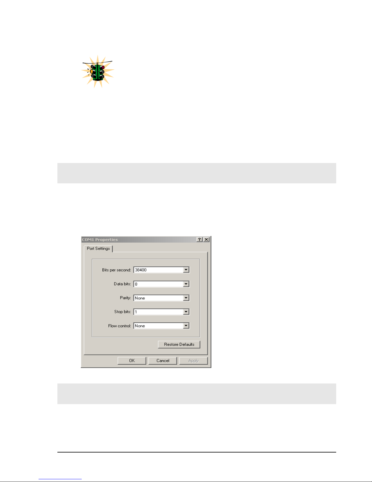
Connect the console port on the switch to the serial port on the computer using the serial
cable listed above. The settings for the HyperTerminal software emulating a VT100 are
shown in Figure 1 below. Make sure the serial parameters are set as shown (or bps =
38400, data bits=8, parity=none, stop bits=1, flow control=none).
FIGURE 1 - HyperTerminal screen showing the serial settings
Console screen
Once the console cable is connected to the PC and the software configured, MNS-6K
legal disclaimers and other text scrolls by on the screen.
25
Page 27

MAGNUM 6K SWITCHES, MNS-6K USER GUIDE
The switch has three modes of operation – Operator (least privilege), Manager and
Configuration. The prompts for the switches change as the switch changes modes from
Operator to Manager to Configuration. The prompts are shown in Figure 2 below, with a
brief explanation of what the different prompts indicate.
Magnum6K> Operator Level – for running operations queries
Magnum6K# Manager Level – for setting and reviewing commands
Magnum6K## Configuration Level – for changing the switch parameter values
FIGURE 2 - Prompt indicating the switch model number as well as mode of operation – note the
commands to switch between the levels is not shown here.
The prompt can be changed by the user. See the Chapter on Miscellaneous Commands,
sub section Prompt for more details. This manual was documented on a Magnum 6K25
switch, and for clarity, the prompt shown in the manual will be
FoUsr additional information on default users, user levels and more, see
j
er Management in this guide.
Magnum6K25
Logging in for the first time
For the first time, use the default user name and passwords assigned by GarrettCom for
the Magnum 6K family of switches. They are:
Username – manager Password – manager
Username – operator Password – operator
We recommend you login as manager for the first time to set up the IP address as well as
change user passwords or create new users.
Setting the IP parameters
To setup the switch, the IP address and other relevant TCP/IP parameters have to be
specified. A new GarrettCom Magnum switch looks for a DHCP or a BootP server. If a
DHCP or a BootP server is present, the switch will be assigned an IP address from those
servers. Failing to find these servers, the IP address is automatically assigned to
192.168.1.2 with a netmask of 255.255.255.0.
26
Page 28
MAGNUM 6K SWITCHES, MNS-6K USER GUIDE
Should a situation arise when there are multiple new switches powered up at the same
time, there could be a situation of duplicate IP addresses. In this situation, only one
Magnum switch will be assigned the IP address of 192.168.1.2 and netmask of
255.255.255.0. The other switches will not be assigned an IP address till the static IP
address of 192.168.1.2 is freed up or reassigned.
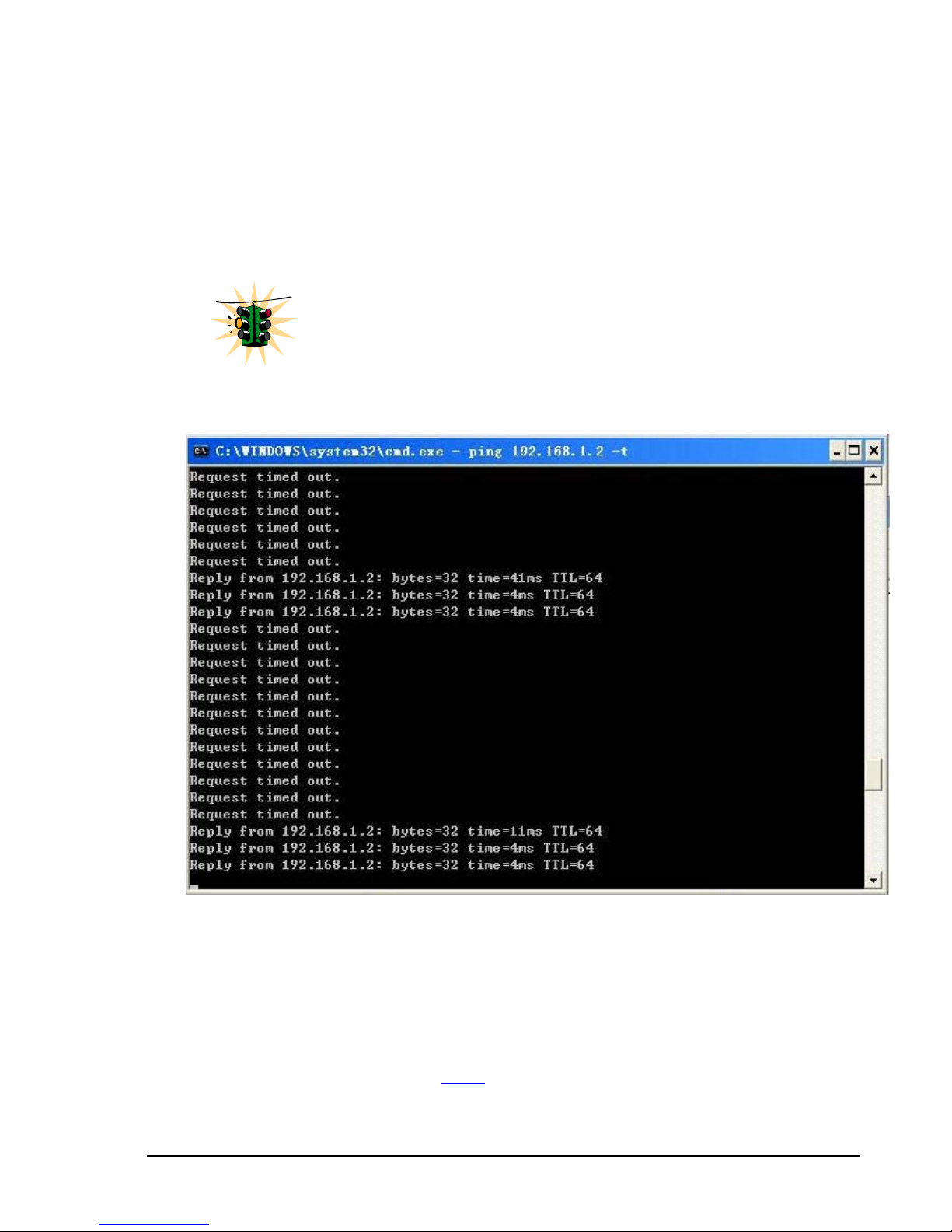
This situation may not be prevalent in all cases. As the switch tries to
determine the mode of operation and its IP address it may assign and
release the IP address a number of times. A continuous ping to the switch
will show an intermittent response as this happens. This is normal
behavior and is shown below. Once the switch assigns itself an IP address
the intermittent ping issue is no longer prevalent.
FIGURE 3 – As the switch tries to determine its mode of operation and its IP address, it may assign and
release the IP address a number of times. A continuous ping to the switch will show an intermittent response
To change the IP address, please ensure that the IP address to be assigned to the switch is
known or contact your system/network administrator to get the IP address information.
Follow the steps listed below to configure the IP address manually.
• Ensure the power is off
• Follow the steps described above
console software
for connecting the console cable and setting the
27
Page 29

MAGNUM 6K SWITCHES, MNS-6K USER GUIDE
• Power on the switch
• Once the login prompt appears, login as manager using default password (manager)
• Configure the IP address, network mask and default gateway as per the IP addressing
scheme for your network
• Set the Manager Password (recommended–refer to next section)
• Save the settings (without saving, the changes made will be lost)
• Power off the switch (or a software reboot as discussed below)
• Power on the switch – login with the new login name and password
• From the PC (or from the switch) ping the IP address specified for the switch to
ensure connectivity
• From the switch ping the default gateway specified (ensure you are connected to the
network to check for connectivity) to ensure network connectivity
Syntax ipconfig [ip=<ip-address>] [mask=<subnet-mask>] [dgw=<gateway>]
[add|del]
Magnum6K25# ipconfig ip=192.168.1.150 mask=255.255.255.0 dgw=192.168.1.10
Magnum6K25# save
FIGURE 4 - Setting IP address on the switch
This document assumes the reader is familiar with IP addressing schemes as well as how
net mask is used and how default gateways and routers are used in a network.
Reboot gives an opportunity to save the configuration prior to shutdown. For a reboot –
simply type in the command “reboot”. (Note – even though the passwords are not
changed, they can be changed later.)
Magnum6K25# reboot
Proceed on rebooting the switch? [ 'Y' or 'N' ] Y
Do you wish to save current configuration? [ 'Y' or 'N' ] Y
Magnum6K25#
FIGURE 5 - Rebooting the switch
MNS-6K forces an answer the prompts with a “Y” or a “N” to prevent accidental
keystroke errors and loss of work.
The parameters can be viewed at any time by using the ‘show’ command. The show
command will be covered in more detail later in various sections throughout the
document.
Magnum6K25# show setup
28
Page 30

MAGNUM 6K SWITCHES, MNS-6K USER GUIDE
Version : Magnum 6K25 build 14.1 Jul 28 2008 07:51:45
MAC Address : 00:20:06:25:b7:e0
IP Address : 192.168.1.150
Subnet Mask : 255.255.255.0
Gateway Address : 192.168.1.10
CLI Mode : Manager
System Name : Magnum6K25
System Description : 25 Port Modular Ethernet Switch
System Contact : support@garrettcom.com
System Location : Fremont, CA
System ObjectId : 1.3.6.1.4.1.553.12.6
Magnum6K25# show sysconfig
System Name : Magnum6K25
System Contact : support@garrettcom.com
System Location : HO, Fremont, CA
Boot Mode : manual
Inactivity Timeout(min) : 10
Address Age Interval(min) : 300
Inbound Telnet Enabled : Yes
Web Agent Enabled : Yes
Time Zone : GMT-08hours:00minutes
Day Light Time Rule : USA
System UpTime : 36 Days 7 Hours 49 Mins 48 Secs
Magnum6K25#
FIGURE 6 - Viewing the basic setup parameters. You can use ‘show setup’ or ‘show sysconfig’ to view
setup parameters
Some of the parameters in the Magnum 6K family of switches are shown above. The list
of parameters below indicates some of the key parameters on the switch and the
recommendations for changing them (or optionally keeping them the same).
Privilege levels
Two privilege levels are available - Manager and Operator. Operator is at privilege level
1 and the Manager is at privilege level 2 (the privilege increases with the levels). For
example, to set up a user for basic monitoring capabilities use lower number or operator
level privilege (Level 1)
The Manager level provides all Operator level privileges plus the ability to perform
system-level actions and configuration commands. To select this level, enter the ‘enable
<user-name>’ command at the Operator level prompt and enter the Manager password,
when prompted.
Syntax enable <user-name>
For example, switching from an Operator level to manager level, using the ‘enable’
29
Page 31

MAGNUM 6K SWITCHES, MNS-6K USER GUIDE
command is shown below in Figure 6
Magnum6K25> enable manager
Password: *******
Magnum6K25#
FIGURE 7 - Switching users and privilege levels. Note the prompt changes with the new privilege level.
Operator Privileges
Operator privileges allow views of the current configurations but do not allow changes to
the configuration. A ">" character delimits the Operator-level prompt.
Manager Privileges
Manager privileges allow configuration changes. The changes can be done at the manager
prompt or for global configuration as well as specific configuration. A “#” character
delimits any Manager prompt.
User management
A maximum of five users can be added per switch for MNS-6K and a maximum of
twenty users can be added for MNS-6K-SECURE. Users can be added, deleted or
changed from a manager level account. There can be more than one manager account,
subject to the maximum number of users on the switch.
MNS-6K-SECURE allows a maximum of twenty (20) users. Using MNS-6Ksecure you can also configure access to the switch using TACACS+ capabilities,
described later on in this manual.
Add User
To add a user, use the command “add” as shown below. The user name has to be a unique
name and can be up to 24 characters long. The password is recommended to be at least 8
characters long with a mix of upper case, lower case, numbers and special characters.
Syntax add user=<name> level=<number>
30
Page 32

MAGNUM 6K SWITCHES, MNS-6K USER GUIDE
Magnum6K25# user
Magnum6K25(user)## add user=peter level=2
Enter User Password:******
Confirm New Password:******
Magnum6K25(user)##
FIGURE 8 - Adding a user with Manager level privilege
In this example, user ‘peter’ was added with Manager privilege.
Delete User
Syntax delete user=<name>
Magnum6K25(user)##delete user=peter
Confirm User Deletion(Y/N): Y
User successfully deleted
Magnum6K25(user)##
FIGURE 9 - Deleting a user
In this example, user ‘peter’ was deleted.
Modify Pass word
Syntax passwd user=<name>
Magnum6K25(user)## passwd user=peter
Enter New Password:******
Confirm New Password :******
Password has been modified successfully
Magnum6K25(user)##
FIGURE 10 - Changing the password for a specific user
In this example, password for ‘peter’ was modified.
Strong passwords should be 8 to 32 characters long and should include upper
case, lower case, numerals as well as special characters such as space, ! @ # $ %
^ & * ( ) _ - + =
Modify the Privilege Level
Syntax chlevel user=<name> level=<number>
Magnum6K25(user)## chlevel user=peter level=1
Access Permission Modified
31
Page 33

MAGNUM 6K SWITCHES, MNS-6K USER GUIDE
Magnum6K25(user)##
FIGURE 11 - Changing the privilege levels for a user
In this example, user ‘peter’ was modified to Operator privileges.
Modifying Access Privileges
User access allows the network administrators to control as to who has read and write
access and for which set of command groups. The command groups are defined as the set
of commands within a specific function such as VLAN, Access privileges (as described in
this section), user ids and managing those and more. Further, administrators can also
control as to what protocols are used by users (e.g. web or SSH but not telnet).To control
access privileges, the commands used are
Syntax useraccess user=<name> service=<telnet|web> <enable|disable> - defines
the services available to the user to access the device for modifying the configuration
Syntax useraccess user=<name> group=<list> type=<read|write>
<enable|disable> - set read or write access for the command group
Syntax useraccess groups – displays the current groups
Where
user=<name> specifies the user id
service=<telnet|web> specifies which service (telnet or web) the user has access to.
<enable|disable> specifies whether the services are allowed or not allowed
group=list – specifies which group the user belongs to
groups – specifies the groups the user has access to. The groups are defined as system,
user, access, device, port, vlan, portsec, ps, mirror, lacp, stp, igmp, software, file,
debug
type=<read|write> - specifies whether the user has authority to change the
configuration or not
Magnum6K25# user
Magnum6K25(user)## useraccess
Usage
useraccess user=<name> service=<telnet|web|acl> <enable|disable>
useraccess user=<name> group=<list> type=<read|write> <enable|disable>
useraccess groups
Magnum6K25(user)## add user=peter level=2
Enter User Password : *****
Confirm New Password : *****
32
Page 34

MAGNUM 6K SWITCHES, MNS-6K USER GUIDE
Magnum6K25(user)## useraccess user=peter group=vlan,user,system type=read enable
Access rules set for Read Operation.
Groups: All Command Groups.
ML2400(user)## show users
Sl# Username Access Permissions
--- -------- ----------------- 1 manager Manager
Read Access: All Command Groups
Write Access: All Command Groups
2 operator Operator
Read Access: All Command Groups
Write Access: All Command Groups
3 peter Manager
Read Access: All Command Groups
Write Access: All Command Groups
Magnum6K25(user)## exit
Magnum6K25#
FIGURE 12 – Creating user access privileges
After this command, user Peter will not have read access to the VLAN, system and user
groups.
In another example, if the user Peter is not allowed to access the switch using telnet, the
access can be blocked using the steps shown below:
Magnum6K25# user
Magnum6K25(user)## add user=peter level=2
Enter User Password :*****
Confirm New Password :*****
Magnum6K25(user)## useraccess user=peter service=telnet disable
Telnet Access Disabled.
FIGURE 13 – Creating user access privileges
After this command, user Peter will not have telnet access to the switch. User Peter only
has console access or SWM access (or access via SSH for MNS-6K-SECURE)
The user “peter” has to be added before this command can be successfully
executed.
33
Page 35

MAGNUM 6K SWITCHES, MNS-6K USER GUIDE
Help
Typing the ‘help’ command lists the commands you can execute at the current privilege
level. For example, typing ‘help’ at the Operator level shows
Magnum6K25> help
logout ping set
terminal telnet walkmib
Contextless Commands:
! ? clear
enable exit help
show whoami
alarm
Magnum6K25>
FIGURE 14 - Help command
Displaying Help for an Individual Command
Help for any command that is available at the current context level can be viewed by
typing help followed by enough of the command string to identify the command.
Syntax help
<command string>
For example, to list the Help for the ‘set time’ command
Magnum6K25# help set time
set time : Sets the device Time
Usage
set time hour=<0-23> min=<0-59> sec=<0-59> [zone=GMT[+/-]hh:mm]
Magnum6K25#
FIGURE 15 - Help for a specific command
Viewing options for a command
The options for a specific command can be displayed by typing the command and
pressing enter.
Syntax command
Magnum6K25# show <Enter>
Usage
show active-stp
show active-snmp
<Enter>
34
Page 36

MAGNUM 6K SWITCHES, MNS-6K USER GUIDE
show active-vlan
show address-table
show age
show alarm
show arp
show auth <config|ports>
show backpressure
show bootmode
--more--
FIGURE 16 - Options for the ‘show’ command
Context help
Other ways to display help, specifically, with reference to a command or a set of
commands, use the TAB key.
Syntax <TAB>
Syntax <Command string> <TAB>
Syntax <First character of the command> <TAB>
For example, following the syntax listed above, the <TAB> key will list the available
commands in the particular privilege level:
Magnum6K25> <TAB>
?
alarm
clear
enable
exit
help
logout
ping
set
show
telnet
terminal
walkmib
whoami
Magnum6K25>
FIGURE 17 - Listing commands available (at the operator level)
OR
Magnum6K25> s <TAB>
set
show
Magnum6K25>
FIGURE 18 - Listing commands starting with a specific character
OR
35
Page 37

MAGNUM 6K SWITCHES, MNS-6K USER GUIDE
Magnum6K25> se<TAB>
password
timeout
vlan
Magnum6K25> set
FIGURE 19 - Listing commands options – note the command was not completed and the TAB key
completed the command.
Exiting
To exit from the CLI interface and terminate the console session use the ‘logout’
command. The logout command will prompt you to ensure that the logout was not
mistakenly typed.
Syntax logout
Magnum6K25# logout
Logging out from the current session...[ 'Y' or 'N'] Y
Connection to the host lost
FIGURE 20 – logout command
Upgrading to MNS-6K-SECURE
MNS-6K-SECURE license can be purchased with the purchase of the switch. In
that case a license key will be issues to you with the delivery of the switch. This
license key will be needed to upgrade the version.
Any MNS-6K switch can be upgraded to MNS-6K-SECURE by purchasing the
necessary license key for the switch. Once the license key is obtained, the
command to upgrade the switch is
Syntax authorize secure key=<16character license key> - Upgrade MNS-6K to MNS-6KSECURE
Magnum6K25# authorize secure key=1122334455667788
Security Module Successfully Authorized
Please Save Configuration..
Magnum6K25# save
36
Page 38

MAGNUM 6K SWITCHES, MNS-6K USER GUIDE
Saving current configuration
Configuration saved
Saving current event logs
Event logs saved
Magnum6K25#
FIGURE 21 – Upgrading to MNS-6K-SECURE
After the license key is entered – please use the save command to save the key in
flash memory. It is recommended to preserve the information for future use.
List of commands in this chapter
Syntax ipconfig [ip=<ip-address>] [mask=<subnet-mask>] [dgw=<gateway>]
[add|del] – to set IP address on the switch
Syntax save – save changes made to the configuration
Syntax reboot – restart the switch – same effect as physically turning off the power
Syntax show setup – show setup parameters
Syntax show config – show setup parameters configured
Syntax enable <user-name> - changing the privilege level
Syntax add user=<name> level=<number> - adding a user
Syntax delete user=<name> - deleting a user
Syntax passwd user=<name> - changing a password for a user
Syntax chlevel user=<name> level=<number> - changing the user privilege level
Syntax help
Syntax command
<command string>
<Enter>
- options for a command
- help for a specific command
37
Page 39

MAGNUM 6K SWITCHES, MNS-6K USER GUIDE
Syntax <TAB> - listing all commands available at the privilege level
Syntax <command string> <TAB> - options for a command
Syntax <first character of the command> <TAB> - listing commands starting with the character
Syntax logout – logout from the CLI session
Syntax useraccess user=<name> service=<telnet|web> <enable|disable> - defines the
services available to the user to access the device for modifying the configuration
Syntax useraccess user=<name> group=<list> type=<read|write> <enable|disable> - set
read or write access for the command group
Syntax useraccess groups – displays the current groups
Syntax authorize secure key=<16character license key> - Upgrade MNS-6K to MNS-6KSECURE
38
Page 40

3 – IP Address and System
Information
First simple steps to follow…
his section explains how the Magnum 6K family of switches can be setup using other
automatic methods such as bootp and DHCP. Besides this, other parameters required for
T
proper operation of the switch in a network are discussed.
Chapter
3
IP Addressing
j
It is assumed that the user has familiarity with IP addresses, classes of IP
addresses and related netmask schemes (e.g. class A, Class B and Class C
addressing).
Importance of an IP address
Without an IP address, the switch will operate as a standalone Layer 2 switch. Without an IP
address, you cannot
• Use the web interface to manage the switch
• Use telnet to access the CLI
• Use any SNMP Network Management software to manage the switch
• Use NTP protocol or an NTP server to synchronize the time on the switch
• Use TFTP or FTP to download the configurations or upload software updates
• Run ping tests to test connectivity
To set the IP address, please refer to the section in Chapter 2 – Setting IP Parameters.
Once the IP address is set, the CLI can be accessed via the telnet programs as
well as the console interface. From now on – all commands discussed are
accessible from the CLI – irrespective of the access methods – serial port or in
band using telnet.
39
Page 41

MAGNUM 6K SWITCHES, MNS-6K USER GUIDE
To verify the IP address settings, the ‘show ipconfig’ command can be used.
Magnum6K25> show ipconfig
IP Address : 192.168.1.150
Subnet Mask : 255.255.255.0
Default Gateway : 192.168.1.10
Magnum6K25>
FIGURE 22 - Checking the IP settings
Besides manually assigning IP addresses, there are other means to assign an IP address
automatically. The two most common procedures are using DHCP and bootp.
D
HCP and bootp
D
j
routers, VoIP phones and more. Both of them can work independent of each other. Both
of them are widely used in the industry. It’s best to check with your network administrator
as to what protocol to use and what the related parameters are. DHCP and bootp require
respective services on the network. DHCP and bootp can automatically assign an IP
address. It is assumed that the reader knows how to setup the necessary bootp parameters
(usually specified on Linux/UNIX systems in /etc/boopttab1).
HCP is commonly used for setting up addresses for computers, users and
o
ther user devices on the network. bootp is the older cousin of DHCP and
is used for setting up IP addresses of networking devices such as switches,
Bootp Database
Bootp keeps a record of systems supported in a database – a simple text file. On most
systems, the bootp service is not started as a default and has to be enabled. A sample entry
by which the bootp software will look up the database and update the IP address and
subnet mask of the switch would be as follows
M6k25switch:\
ht=ether:\
ha=002006250065:\
ip=192.168.1.88:\
sm=255.255.255.0:\
gw=192.168.1.1:\
hn:\
vm=rfc1048
where
M6k25switch: is a user-defined symbolic name for the switch
1
Note – on Windows systems – the location of the file will vary depending on which software is being used.
40
Page 42

MAGNUM 6K SWITCHES, MNS-6K USER GUIDE
ht: is the “hardware type”. For the Magnum 6K family of switches, set this to ether (for
Ethernet).
This tag must precede the “
ha” tag.
ha: is the “hardware address”. Use the switch’s 12-digit MAC address
ip: is the IP address to be assigned to the switch
sm: is the subnet mask of the subnet in which the switch is installed
Configuring Auto/DHCP/Bootp/Manual
By default, the switch is configured for ‘auto’. As describer earlier in Chapter 2, in the
auto mode, the switch will first look for a DHCP server. If a DHCP server is not found, it
will then look for a BootP server. If that server is not found, the switch will first inspect to
see if the IP address 192.168.1.2 with a netmask of 255.255.255.0 is free. If the IP address
is free, MNS-6K will assign the switch that IP address. If the address is not free, MNS-6K
will poll the network for DHCP server then BootP server then check if the IP address
192.68.1.2 is freed up. This mode of assigning the IP address can be changed by using the
‘set bootmode’ command.
Syntax set bootmode type=<dhcp|bootp|manual|auto>
[bootimg=<enable|disable>] [bootcfg=[<enable|disable>] – assign the boot mode
for the switch
Where
<dhcp|bootp|manual|auto> - where
dhcp – look only for DHCP servers on the network for the IP address. Disable
bootp or other modes
bootp – look only for bootp servers on the network. Disable dhcp or other mode
manual – do not set the IP address automatically
auto - the switch will first look for a DHCP server. If a DHCP server is not found,
it will then look for a BootP server. If that server is not found, the switch will
check to see if the switch had a pre-configured IP address. If it did, the switch
would be assigned that IP address. If the switch did not have a pre-configured
IP address, it would inspect if the IP address 192.168.1.2 with a netmask of
255.255.255.0 is free. If the IP address is free, MNS-6K will assign the switch
that IP address. If the address is not free, MNS-6K will poll the network for
DHCP server then BootP server then check if the IP address 192.68.1.2 is freed
up
bootimg=<enable|disable> - valid with type=bootp only. This option allows the
switch to load the image file from the BootP server. This is useful when a new switch
is put on a network and the IT policies are set to load only a specific MNS-6Kimage
which is supported and tested by IT personnel.
bootcfg=<enable|disable> - valiad with type=bootp only. This option allows the
switch to load the configuration file from the BootP server. This is useful when a new
41
Page 43

MAGNUM 6K SWITCHES, MNS-6K USER GUIDE
switch is put on a network and the specific configurations are loaded from a
centralized BootP server
Magnum6K25# set bootmode type=dhcp
Save Configuration and Restart System
Magnum6K25# set bootmode type=auto
Save Configuration and Restart System
Magnum6K25# set bootmode type=bootp bootimg=enable bootcfg=disable
Network application image download is enabled.
Network application config download is disabled.
Save Configuration and Restart System
Magnum6K25#
FIGURE 23 - Changing the boot mode of the switch
Using Telnet
By default, the telnet client is enabled on the GarrettCom Magnum 6K family of switches.
MNS-6K supports five simultaneous sessions on a switch – four telnet sessions and one
console session. This allows many users to view, discuss or edit changes to the MNS-6K.
This also becomes useful as two remote people want to view the commands and other
settings on the switch. The telnet client can be disabled by using the “telnet disable”
command. Telnet can also be disabled for a specific user by using the “useraccess”
command discussed in Chapter 2.
Multiple telnet sessions started from the CLI interface or the command line are serviced
by MNS-6K in a round robin fashion – i.e. one session after another. If one telnet session
started from MNS-6K interface is downloading a file, the other windows will not be
serviced till the file transfer is completed.
Syntax telnet <enable|disable>
Magnum6K25# configure access
Magnum6K25(access)## telnet enable
Access to Telnet already enabled
Magnum6K25(access)## exit
Magnum6K25#
FIGURE 24 - Changing telnet access – note in this case, the enable command was repeated without
any effect to the switch
The ‘show console’ command can show the status of the telnet client as well as other
console parameters.
42
Page 44

MAGNUM 6K SWITCHES, MNS-6K USER GUIDE
Magnum6K25# show console
Console/Serial Link
Inbound Telnet Enabled : Yes
Outbound Telnet Enabled : Yes
Web Console Enabled : Yes
SNMP Enabled : Yes
Terminal Type : VT100
Screen Refresh Interval (sec) : 3
Baud Rate : 38400
Flow Control : None
Session Inactivity Time (min) : 10
Magnum6K25#
FIGURE 25 - Reviewing the console parameters – note telnet is enabled
Users can telnet to a remote host from the Magnum 6K family of switches.
Syntax telnet <ipaddress> [port=<port number>]
The default port for telnet is 23.
Magnum6K25# show ipconfig
IP Address : 192.168.1.11
Subnet Mask : 255.255.255.0
Gateway Address : 192.168.1.1
Magnum6K25# telnet 192.168.1.1 port=2097
FIGURE 26 - Example of a telnet session
While MNS-6K times out an idle telnet session, it may be useful to see who is currently connected to
the switch. It may also be useful for a person to remotely terminate a telnet session. To facilitate this,
MNS-6K supports two commands
Syntax show session
Syntax kill session id=<session> - terminate a telnet session
43
Page 45

MAGNUM 6K SWITCHES, MNS-6K USER GUIDE
Magnum6K25# user
Magnum6K25(user)## useraccess user=peter service=telnet enable
Telnet Access Enabled.
Magnum6K25(user)## exit
Magnum6K25# show session
Current Sessions:
SL # Session Id Connection User Name User Mode
1 1 163.10.10.14 manager Manager
2 2 163.11.11.15 peter Manager
3 3 163.12.12.16 operator Operator
Magnum6K25# kill session id=3
Session Terminated.
Magnum6K25#
FIGURE 27 – managing and viewing multiple telnet sessions
In the above example, the user with user-id peter is given telnet access (which was disabled earlier in
Chapter 2). Then multiple users telnet into the switch. This is shown using the “show session”
command. The user operator session is then terminated using the “kill session” command.
The default port – port 23 is used for telnet.
A maximum of four simultaneous telnet sessions are allowed at any time on the
switch. The commands in these telnet windows are executed in a round robin – i.e.
if one window takes a long time to finish a command, the other windows may
encounter a delay before the command is completed. For example, if one window
is executing a file download, the other windows will not be able to execute the
command before the file transfer is completed. Another example, if a outbound
telnet session is started from the switch (through a telnet window) then the other
windows will not be able to execute a command till the telnet session is completed.
Using SSH
SSH is available in MNS-6K-SECURE.
The Telnet, rlogin, rcp, rsh commands have a number of security weakness: all
communications are in clear text and no machine authentication takes place. These
commands are open to eavesdropping and tcp/ip address spoofing. Secure Shell or
SSH is a network protocol that allows data to be exchanged over a secure channel
between two computers. SSH uses public/private key RSA authentication to check
the identity of communicating peer machines, encryption of all data exchanged (with
44
Page 46

MAGNUM 6K SWITCHES, MNS-6K USER GUIDE
strong algorithms such as blowfish, 3DES, IDEA etc.). Encryption provides confidentiality and
integrity of data. . The goal of SSH was to replace the earlier rlogin, Telnet and rsh protocols,
which did not provide strong authentication or guarantee confidentiality.
In 1995, Tatu Ylönen, a researcher at Helsinki University of Technology, Finland, designed the
first version of the protocol (now called SSH-1).
In 1996, a revised version of the protocol, SSH-2, was designed, incompatible with SSH-1. SSH-2
features both security and feature improvements over SSH-1. Better security, for example, comes
through Diffie-Hellman key exchange and strong integrity checking via MACs. New features of
SSH-2 include the ability to run any number of shell sessions over a single SSH connection. Since
SSH-1 has inherent design flaws which make it vulnerable to, e.g., man-in-the-middle attacks, it is
now generally considered obsolete and should be avoided by explicitly disabling fallback to SSH-
1. While most modern servers and clients support SSH-2, some organizations still use software
with no support for SSH-2, and thus SSH-1 cannot always be avoided.
In all versions of SSH, it is important to verify unknown public keys before accepting them as
valid. Accepting an attacker's public key as a valid public key has the effect of disclosing the
transmitted password and allowing man in the middle attacks.
SSH is most commonly used
• With an SSH client that supports terminal protocols, for remote administration of the
SSH server computer via terminal (character-mode) console--can be used as an alternative
to a terminal on a headless server;
• In combination with SFTP, as a secure alternative to FTP which can be set up more easily
on a small scale without a public key infrastructure and X.509 certificates
While there are other uses for SSH, the two most common uses are described above and are
relevant to this manual.
SSH uses port 22 as a default. Note – telnet uses port 23 as a default port.
The SSH-2 protocol has a clean internal architecture (defined in RFC 4251) with well-separated
layers. These are:
• The transport layer (RFC 4253). This layer handles initial key exchange and server
authentication and sets up encryption, compression and integrity verification. It exposes
to the upper layer an interface for sending and receiving plaintext packets of up to 32,768
bytes each (more can be allowed by the implementation). The transport layer also arranges
for key re-exchange, usually after 1 GB of data has been transferred or after 1 hour has
passed, whichever is sooner.
45
Page 47

MAGNUM 6K SWITCHES, MNS-6K USER GUIDE
• The user authentication layer (RFC 4252). This layer handles client authentication and
provides a number of authentication methods. Authentication is client-driven, a fact
commonly misunderstood by users; when one is prompted for a password, it may be the
SSH client prompting, not the server. The server merely responds to client's
authentication requests. Widely used user authentication methods include the following:
o "password": a method for straightforward password authentication, including a
facility allowing a password to be changed. This method is not implemented by all
programs.
o "publickey": a method for public key-based authentication, usually supporting at
least DSA or RSA keypairs, with other implementations also supporting X.509
certificates.
o "keyboard-interactive" (RFC 4256): a versatile method where the server sends one
or more prompts to enter information and the client displays them and sends back
responses keyed-in by the user. Used to provide one-time password authentication
such as S/Key or SecurID. Used by some OpenSSH configurations when PAM is
the underlying host authentication provider to effectively provide password
authentication, sometimes leading to inability to log in with a client that supports
just the plain "password" authentication method. This method is not supported.
o GSSAPI authentication methods which provide an extensible scheme to perform
SSH authentication using external mechanisms such as Kerberos 5 or NTLM,
providing single sign on capability to SSH sessions. These methods are usually
implemented by commercial SSH implementations for use in organizations,
though OpenSSH does have a working GSSAPI implementation. This method is
not supported.
• The connection layer (RFC 4254). This layer defines the concept of channels, channel
requests and global requests using which SSH services are provided. A single SSH
connection can host multiple channels simultaneously, each transferring data in both
directions. Channel requests are used to relay out-of-band channel specific data, such as
the changed size of a terminal window or the exit code of a server-side process. The SSH
client requests a server-side port to be forwarded using a global request. Standard channel
types include:
o "shell" for terminal shells, SFTP and exec requests (including SCP transfers)
o "direct-tcpip" for client-to-server forwarded connections
o "forwarded-tcpip" for server-to-client forwarded connections
The commands for SSH are
Syntax ssh <enable|disable|keygen> - enable or disable the server. Also can be used for generating the
key used by ssh
Syntax ssh port=<port|default> - select a different port number for SSH communication
Syntax show ssh – display the ssh settings
Magnum6K25# access
46
Page 48

MAGNUM 6K SWITCHES, MNS-6K USER GUIDE
Magnum6K25 (access)## ssh ?
ssh <enable|disable> : Enables or Disables the SSH
ssh keygen : Generate Security Keys.
ssh port=<port|default> : Set TCP/IP Port
Usage
ssh <enable|disable|keygen>
ssh port=<port|default>
Magnum6K25 (access)## show ssh
SSH is disabled
Magnum6K25 (access)## ssh keygen
SSH Key Generation Started. This will take several minutes to complete.
Upon completion, the keys will be saved to flash memory.
Magnum6K25 (access)## ssh enable
Enabling Access to SSH
ML2400(access)## show ssh
SSH is enabled
Magnum6K25 (access)## telnet disable
ERROR: Connected through telnet.
Magnum6K25 (access)## exit
Magnum6K25# show console
Console/Serial Link
Inbound Telnet Enabled : Yes
Outbound Telnet Enabled : Yes
Web Console Enabled : Yes
SSH Server Enabled : Yes
Modbus Server Enabled : Yes
SNMP Enabled : Yes
Terminal Type : VT100
Screen Refresh Interval (sec) : 3
Baud Rate : 38400
Flow Control : None
Session Inactivity Time (min) : 10
ML2400# show sysconfig
System Name : Magnum 6K25
System Contact : support@garrettcom.com
System Location : Fremont, CA
47
Page 49

MAGNUM 6K SWITCHES, MNS-6K USER GUIDE
Boot Mode : manual
Inactivity Timeout(min) : 500
Address Age Interval(min) : 300
Inbound Telnet Enabled : Yes
Web Agent Enabled : Yes
SSH Server enabled : Yes
Modbus Server Enabled : Yes
Time Zone : GMT-08hours:00minutes
Day Light Time Rule : None
System UpTime : 0 Days 0 Hours 2 Mins 31 Secs
ML2400#
FIGURE 28 – setting up ssh – since telnet sends the information in clear text, make sure that telnet is disabled to secure
the switch. Do not telnet to the switch to disable telnet. Preferred method is to do that via the console or using SWM. The
client access is not shown here. Commonly an application like PUTTY is used to access the switch via ssh. Use the show
console command to verify telnet is turned off
SSH sessions cannot originate from the switch to another device.
A maximum of four SSH session can be active at the same time
Domain Name System (DNS)
DNS functionality is available in MNS-6K-SECURE.
Domain Name System (DNS) associates various sorts of information with domain names
or logical computer names. A DNS server provides the necessary services as the "phone
book" for the Internet: it translates human-readable computer hostnames, e.g. google.com or
yahoo.com into the IP addresses that networking equipment needs for communications.
Most organizations deploy an internal DNS server so that the support personnel do not
have to remember IP address, but instead remember logical names. DNS services on
MNS require an interaction with DNS servers. These servers can be defined within MNS-6K using the
command
Syntax set dns [server=<ip>] [domain=<domain name>] <enable|disable|clear> - specify
a DNS server to look up domain names. The sever IP can be a IPV6 address as well as an IPV4
address
Syntax show dns – display the DNS settings
48
Page 50

MAGNUM 6K SWITCHES, MNS-6K USER GUIDE
Magnum6K25# show dns
DNS Server Address : 0.0.0.0
Domain Name : Not Set
DNS Status : Disabled.
Magnum6K25# set dns server=192.168.5.254 domain=customer-domain.com
Domain Name Server Set.
Magnum6K25# show dns
DNS Server Address : 192.168.5.254
Domain Name : customer-domain.com
DNS Status : Disabled.
Magnum6K25# set dns enable
DNS enabled.
Magnum6K25# show dns
DNS Server Address : 192.168.5.254
Domain Name : customer-domain.com
DNS Status : Enabled.
Magnum6K25# ping server
192.168.5.2 is alive, count 1, time = 20ms
Magnum6K25# set dns clear
DNS Information Cleared
Magnum6K25# show dns
DNS Server Address : 0.0.0.0
Domain Name : Not Set
DNS Status : Disabled.
Magnum6K25# ping server
ERROR: Host Not Found
Magnum6K25#
FIGURE 29 – Use of DNS
Domain name information as well as the IP address of the Domain server is needed
before DNS service is enabled.
DNS Server IP address can be an IVv6 address
49
Page 51

MAGNUM 6K SWITCHES, MNS-6K USER GUIDE
Setting serial port parameters
To be compliant with IT or other policies the console parameters can be changed from the CLI
interface. This is best done by setting the IP address and then telnet over to the switch. Once
connected using telnet, the serial parameters can be changed. If you are using the serial port,
remember to set the VT-100 emulation software properties to match the new settings.
Syntax set serial [baud=<rate>] [data=<5|6|7|8>] [parity=<none|odd|even>]
[stop=<1|1.5|2>] [flowctrl=<none|xonxoff>]
Where <rate> = standard supported baud rates
Warning – changing these parameters through the serial port will cause loss of
connectivity – the parameters of the terminals software (e.g. Hyper Terminal etc.)
will also have to be changed to match the new settings.
To see the current settings of the serial port, use the ‘show serial’ command.
Magnum6K25# show serial
Baud Rate : 38400
Data : 8
Parity : No Parity
Stop : 1
Flow Control : None
FIGURE 30 - Querying the serial port settings
System parameters
The system parameters can be queried and changed. To query the system parameters, two
commands are used frequently. They are ‘show sysconfig’ and ‘show setup’. Both the
commands are shown below.
Magnum6K25# show setup
Version : Magnum 6K25 build 14.1 Jul 28 2008 07:51:45
MAC Address : 00:20:06:25:b7:e0
IP Address : 67.109.247.197
Subnet Mask : 255.255.255.224
Gateway Address : 67.109.247.193
CLI Mode : Manager
System Name : Magnum6K25
System Description : 25 Port Modular Ethernet Switch
50
Page 52

MAGNUM 6K SWITCHES, MNS-6K USER GUIDE
System Contact : support@garrettcom.com
System Location : Fremont, CA
System ObjectId : 1.3.6.1.4.1.553.12.6
Magnum6K25#
FIGURE 31 - System parameters using the show setup command. Most parameters here cannot be
changed
Magnum6K25# show sysconfig
System Name : Magnum6K25
System Contact : support@garrettcom.com
System Location : HO, Fremont, CA
Boot Mode : manual
Inactivity Timeout(min) : 10
Address Age Interval(min) : 300
Inbound Telnet Enabled : Yes
Web Agent Enabled : Yes
Time Zone : GMT-08hours:00minutes
Day Light Time Rule : USA
System UpTime : 7 Days 12 Hours 30 Mins 46 Secs
Magnum6K25#
FIGURE 32 - System parameters using the show sysconfig command. Most parameters here can be
changed.
System variables can be changed. Below is a list of system variables which GarrettCom
recommends changing.
System Name: Using a unique name helps you to identify individual devices in a
network.
System Contact and System Information: This is helpful for identifying the
administrator responsible for the switch and for identifying the locations of individual
switches.
To set these variables, change the mode to be SNMP configuration mode from the
manager mode.
Syntax snmp
Syntax setvar [sysname|syscontact|syslocation]=<string> where string is a character
string, maximum 24 characters long
51
Page 53

MAGNUM 6K SWITCHES, MNS-6K USER GUIDE
Magnum6K25# snmp
Magnum6K25(snmp)## setvar ?
setvar : Configures system name, contact or location
Usage:
setvar [sysname|syscontact|syslocation]=<string>
Magnum6K25(snmp)## setvar syslocation=Fremont
System variable(s) set successfully
Magnum6K25(snmp)## exit
Magnum6K25#
FIGURE 33 - Setting the system name, system location and system contact information
Date and time
It may be necessary to set the day, time or the time zone manually. This can be done by
using the ‘set’ command with the necessary date and time options. These are listed below:
Syntax set timezone GMT=[+ or -] hour=<0-14> min=<0-59>
Syntax set date year=<2001-2035> month=<1-12> day=<1-31>
[format=<mmddyyyy|ddmmyyyy|yyyymmdd>]
Syntax set time hour=<0-23> min=<0-59> sec=<0-59>
Thus to set the time to be 08:10 am in the -8 hours from GMT (PST or time zone on west
coast of USA) and to set the date to be 15 October 2003, the following set of commands
are used.
Magnum6K25# set time hour=8 min=30 sec=0
success in setting device time
Magnum6K25# show time
Time : 8:30:04
Magnum6K25# show timezone
Timezone : GMT-08hours:00minutes
Magnum6K25# set date year=2003 month=10 day=15
Success in setting device date
Magnum6K25# show date
System Date : Wednesday 10-15-2003 (in mm-dd-yyyy format)
Magnum6K25#
FIGURE 34 - Setting the system date, time and time zone
Rebooting the switch resets the time to the default. Synchronizing with the time server
resets the time. Other relevant date and time commands are:
52
Page 54

MAGNUM 6K SWITCHES, MNS-6K USER GUIDE
Syntax set timeformat format=<12|24>
Syntax
set daylight country=< country name>
Magnum6K25# set daylight ?
set daylight : Sets the day light location
Usage
set daylight country=<name>
Magnum6K25# set daylight country=USA
Success in setting daylight savings to the given location/country USA
Magnum6K25# show daylight
Daylight savings location name : USA
Magnum6K25#
FIGURE 35 - Setting the system daylight saving time
See Appendix 3 for additional information on Daylight Savings Time. The lists of countries for the time
zone are
Australia, Belgium, Canada, Chile, Cuba, Egypt, France, Finland, Germany, Greece, Iraq, Italy, London,
Namibia, Portugal, Russia, Spain, Sweden, Switzerland, Syria, USA
Network time (SNTP Client)
Many networks synchronize the time using a Network time server. The network time
server provides time to the different machines using the Simple Network Time Protocol
(SNTP). To specify the SNTP server, one has to
1) Set the IP parameters on the switch
2) Define the SNTP parameters
To set the SNTP parameter, enter the SNTP configuration mode from the manager. The
‘setsntp, sync, sntp’ commands can then be used to setup the time synchronization
automatically from the SNTP server. Note it is not sufficient to setup the SNTP variables.
Make sure to setup the synchronization frequency as well as enable SNTP. The list of
relevant commands is listed below.
Syntax setsntp server =<ipaddress> timeout =<1-10> retry =<1-3>
Syntax sync [hour=<0-24>] [min=<0-59>] (default = 24 hours)
The time zone and daylight savings time information have to be set for SNTP
server to set the proper time
53
Page 55

MAGNUM 6K SWITCHES, MNS-6K USER GUIDE
y
Syntax sntp [enable|disable]
For example, to set the SNTP server to be 204.65.129.2012 (with a time out of 3 seconds
and a number of retries set to 3 times); allowing the synchronization to be ever 5 hours, the
following commands are used
Magnum6K25# sntp
Magnum6K25(sntp)## setsntp server=204.65.129.201 timeout=3 retry=3
SNTP server is added to SNTP server database
Magnum6K25(sntp)## sync hour=5
Magnum6K25(sntp)## sntp enable
SNTP is already enabled.
Magnum6K25(sntp)## exit
Magnum6K25(sntp)#
Do not forget to enable sntp
for time s
nchronization.
FIGURE 36 - Setting up SNTP services
Network time (SNTP Server)
SNTP server feature is available in MNS-6K-SECURE only.
Refer to the chapter on SNTP server in this manual.
Saving and loading configuration
After configuration changes are made, all the changes are automatically registered but not saved
i.e. the effect of the change is immediate, however, if power fails, the changes are not saved and
restored, unless the changed are saved using the save command. It is also a good practice to save
the configuration on another server on the network using the tftp or ftp protocols.
2
There are number of public NTP servers. Search on the internet using ‘NTP Servers’ yields the necessary server IP addresses.
54
Page 56

MAGNUM 6K SWITCHES, MNS-6K USER GUIDE
To upgrade to MNS-6K 4.x or MNS-6K-SECURE 14.x, make sure the switch is first
upgraded to version 3.7 or higher
Once the configuration is saved – the saved configuration can be loaded to restore back the
settings. At this time the configuration parameter saved or loaded are not in a human readable
format. The commands for saving and loading configurations on the network are:
Syntax saveconf mode=<serial|tftp|ftp> [<ipaddress>] [file=<name>]
Syntax loadconf mode=<serial|tftp|ftp> [<ipaddress>] [file=<name>]
Make sure the machine specified by the IP address has the necessary services running on it. For
serial connections, x-modem or other alternative methods can be used. File name in many
situations has to be a unique file name as over-writing files is not permitted by most ftp and tftp
servers (or services). Only alpha-numeric characters are allowed in the file name – special
characters like !@#$%&*(\|){/};[,’]” (or other control characters e.g. ^G) are not allowed
Magnum6K25# saveconf mode=tftp 192.168.10.1 file=mag6Kmain
Do you wish to upload the configuration? [ 'Y' or 'N'] Y
FIGURE 37 - Saving the configuration on a tftp server
The “saveconf” and “loadconf” commands, while often used often to
update new software to the Magnum 6K family of switches, are obsolete and
kept for historical reasons. These commands are replaced with the “ftp” or
“tftp” or “xmodem” commands listed below.
Before the software is updated, it is advised to save the configurations. The re-loading of the
configuration is not usually necessary; however, in certain situations it maybe needed and it is
advised to save configurations before a software update. The ‘loadconf’ command requires a
reboot for the new configuration to be active. Without a reboot the older configuration is used by
the Magnum 6K family of switches. When Reboot is selected, the user is prompted: ‘Reboot
Y/N’. Select ‘Y’, the prompt is then: ‘Save Current Configuration?’ You must select ‘No’.
Along with the ftp command listed below, MNS-6K also supports normal ftp as well as passive
ftp. Passive FTP is used by many companies today to work with firewall policies and other
security policies set by companies. The commands for setting the type of ftp are:
Syntax set ftp mode=<normal|passive> - set the ftp mode of operation3
3
FTP uses a set of separate ports for the data stream and command stream. This causes problems in security conscious companies
who prefer that the client initiate the file transfer as well as the stream for the commands. To accommodate that, ftp added the
capability called “passive ftp” in which the client initiating the connection initiates both the data and command connection request.
Most companies prefer passive ftp and GarrettCom MNS-6K provides means to operate in those environments.
55
Page 57

MAGNUM 6K SWITCHES, MNS-6K USER GUIDE
Syntax show ftp- display the current ftp operation mode
With MNS-6K additional capabilities have been added to save and load configurations. The
commands are:
Syntax ftp <get|put|list|del> [type=<app|config|oldconf|script|hosts|log>]
[host=<hostname>] [ip=<ipaddress>] [file=<filename>] [user=<user>]
[pass=<password>] – upload and download information using ftp command
Where
<get|put|list|del> - different ftp operations
[type=<app|config|oldconf|script|hosts|log>] – optional type field. This
is useful to specify whether a log file or host file is uploaded or downloaded.
This can also perform the task of exporting a configuration file or uploading a
new image to the switch
[host=<hostname>] [ip=<ipaddress>] [file=<filename>] [user=<user>]
[pass=<password>] – parameters associated with ftp server for proper
communications with the server
The “sftp” command is available in MNS-6K-SECURE version.
Syntax stftp<get|put| list|del >
[type=<app|config|oldconf|script|hosts|log>] [host=<hostname>]
[ip=<ipaddress>] [file=<filename>] – upload and download information using sftp
(Secure ftp) command
Where
<get|put| list|del > - different sftp operations – get a file from the server or put
the information on the server or list files on the server or delete files from the
server
[type=<app|config|oldconf|script|hosts|log>] – optional type field. This
is useful to specify whether a log file or host file is uploaded or downloaded.
This can also perform the task of exporting a configuration file or uploading a
new image to the switch
[host=<hostname>] [ip=<ipaddress>] [file=<filename>] – parameters
associated with tftp server for proper communications with the server
Syntax tftp <get|put> [type=<app|config|oldconf|script|hosts|log>]
[host=<hostname>] [ip=<ipaddress>] [file=<filename>] – upload and
download information using tftp command
Where
<get|put> - different tftp operations – get a file from the server or put the
information on the server
[type=<app|config|oldconf|script|hosts|log>] – optional type field. This
is useful to specify whether a log file or host file is uploaded or downloaded.
56
Page 58

MAGNUM 6K SWITCHES, MNS-6K USER GUIDE
This can also perform the task of exporting a configuration file or uploading a
new image to the switch
[host=<hostname>] [ip=<ipaddress>] [file=<filename>] – parameters
associated with tftp server for proper communications with the server
Syntax xmodem <get|put> [type=<app|config|oldconf|script|hosts|log>] –
upload and download information using xmodem command and console connection
Where
<get|put> - different xmodem file transfer operations – get a file from the server
or put the information on the server
[type=<app|config|oldconf|script|hosts|log>] – optional type field. This
is useful to specify whether a log file or host file is uploaded or downloaded.
This can also perform the task of exporting a configuration file or uploading a
new image to the switch
The details are conceptually explained in the figure below.
app
app
script
script
config
config
ftp
ftp
or
or
tftp Server
tftp Server
xmodem
xmodem
connection
connection
or
or
MNS-6K
MNS-6K
image
image
CLI
CLI
commands
commands
Configuration
Configuration
parameters
parameters
FIGURE 38 – Based on the sftp, ftp, tftp or xmodem commands – the MNS-6K based switch can
upload or download different types of files and images .Other files such as log files, hosts file can also be
saved or loaded onto a switch
Prior to Release 3.2, the configuration was saved only as a binary object (file). With
Release 3.2 and beyond, the configuration can be saved in the older format – binary
57
Page 59

MAGNUM 6K SWITCHES, MNS-6K USER GUIDE
object or in a newer format as an ASCII (readable) file. The new format is preferred by GarrettCom
and GarrettCom recommends all configuration files be saved in the new format. GarrettCom
recommends saving the configuration in the old format only if there are multiple Magnum 6K family of
switches on the network and they all run different versions of MNS-6K. GarrettCom recommends to
upgrade all switches to the most current release of MNS-6K.
Config files
As shown in the figure above, MNS-6K can now use the ftp, tftp or xmodem commands to
upload and download information to the server running the proper services. One useful capability
provided in MNS-6K is the capability to export the CLI commands (as described in this manual)
used to configure the switch. To do that, for example, using the tftp command, the sequence of
commands are shown below
Magnum6K25# show ftp
Current FTP Mode: NORMAL
Magnum6K25# set ftp mode=passive
FTP Set to Passive Mode
Magnum6K25# show ftp
Current FTP Mode: PASSIVE
Magnum6K25# set ftp mode=normal
FTP Set to Normal Mode
Magnum6K25# show ftp
Current FTP Mode: NORMAL
Magnum6K25# ftp put type=config ip=192.168.5.2 file=config
Do you wish to export configuration file? [ 'Y' or 'N'] Y
Successfully exported the configuration
Magnum6K25#
FIGURE 39 – commands to save the configuration using ftp. Similar options will be specified using tftp etc.
When using the ftp command, use the host command discussed later in this section to define the ftp server
After saving the contents of the saved configuration file are as follows
################################################################
# Copyright (c) 2001-2007 GarrettCom, Inc All rights reserved.
# RESTRICTED RIGHTS
# ---------------------------------
# Use, duplication or disclosure is subject to U.S. Government
# restrictions as set forth in Sub-division (b)(3)(ii) of the
# rights in Technical Data and Computer Software clause at
# 52.227-7013.
#
# This file is provided as a sample template to create a backup
58
Page 60

MAGNUM 6K SWITCHES, MNS-6K USER GUIDE
# of Magnum 6K switch configurations. As such, this script
# provides insights into the configuration of Magnum 6K switch's
# settings. GarrettCom recommends that modifications of this
# file and the commands should be verified by the User in a
# test environment prior to use in a "live" production network.
# All modifications are made at the User's own risk and are
# subject to the limitations of the GarrettCom software End User
# License Agreement (EULA). Incorrect usage may result in
# network shutdown. GarrettCom is not liable for incidental or
# consequential damages due to improper use.
################################################################
#Magnum 6KQ build 4.0 Dec 16 2007 16:41:37
#Modules: 39 99 86 0
#Slot A: 4 Port TP-MDIX Module
#Slot B: 2 Port Fiber10 Module
#Slot C: 4 Port Fiber100 Module
#Slot D: 1 10/100/1000T 1 Giga SFP-1000
##########################################################
# System Manager - This area configures System related #
# information. #
##########################################################
set bootmode type=auto
set timeout=10
access
telnet enable
snmp enable
web enable
ssl enable
exit
##########################################################
# User Accounts - This area configures user accounts for #
# accessing this system. #
##########################################################
user
add user=manager level=2 pass=manager
useraccess user=manager service=telnet enable
useraccess user=manager service=web enable
useraccess user=manager service=acl enable
add user=operator level=1 pass=operator
##########################################################
<additional lines deleted for succinct viewing>
FIGURE 40 – Contents of the config file
Note 1 – the config file only allows certain portions of the file to be edited by a user.
Changing any other part of the file will not allow the file to be loaded as the CRC
computed and stored in the file will not be matched. Should you want to edit, edit the
59
Page 61

MAGNUM 6K SWITCHES, MNS-6K USER GUIDE
System portion of the file only. GarrettCom recommends editing the “script” file (see below)
Note 2 – File names cannot have special characters such as *#!@$^&* space and control characters.
Script files
Script file is a file containing a set of CLI commands which are used to configure the switch. CLI
commands are repeated in the file for clarity, providing guidance to the user editing the file as to
what commands can be used for modifying variables used by MNS-6K. The script file does not
have a check sum at the end and is used for configuring a large number of switches easily. As with
any configuration file that is uploaded, GarrettCom recommends that modifications of this file
and the commands should be verified by the User in a test environment prior to use in a "live"
production network.
The commands for user access can be encrypted when saving the script file. Please
note that when the script file is loaded back to the switch, please make sure the
encrypted password is replaced back in clear text. To encrypt and save the config
file, use the CLI command
Syntax set secrets <hide|show> - hides or encrypts the user access password. Default is show
The script file will look familiar as all the commands saved in the script file are described in this manual.
A sample of the script file is shown below.
################################################################
# Copyright (c) 2001-2007 GarrettCom, Inc All rights reserved.
# RESTRICTED RIGHTS
# ---------------------------------
# Use, duplication or disclosure is subject to U.S. Government
# restrictions as set forth in Sub-division (b)(3)(ii) of the
# rights in Technical Data and Computer Software clause at
# 52.227-7013.
#
# This file is provided as a sample template to create a backup
# of Magnum 6K switch configurations. As such, this script
# provides insights into the configuration of Magnum 6K switch's
# settings. GarrettCom recommends that modifications of this
# file and the commands should be verified by the User in a
# test environment prior to use in a "live" production network.
# All modifications are made at the User's own risk and are
# subject to the limitations of the GarrettCom software End User
# License Agreement (EULA). Incorrect usage may result in
# network shutdown. GarrettCom is not liable for incidental or
# consequential damages due to improper use.
################################################################
##########################################################
60
Page 62

MAGNUM 6K SWITCHES, MNS-6K USER GUIDE
# System Manager - This area configures System related #
# information. #
##########################################################
set bootmode type=manual
ipconfig ip=192.168.5.5 mask=0.0.0.0 dgw=0.0.0.0
set timeout=10
access
telnet enable
snmp enable
web=enable
exit
##########################################################
# User Accounts - This area configures user accounts for #
# accessing this system. #
##########################################################
user
add user=manager level=2
passwd user=manager
manager
add user=operator level=1
passwd user=operator
operator
exit
<additional lines deleted for succinct viewing>
FIGURE 41 – Example of Script file. Note all the commands are CLI commands. This script provides
insights into the configuration of Magnum MNS-6K settings. GarrettCom recommends that modifications
of this file and the commands should be verified by the User in a test environment prior to use in a "live"
production network
To ease the process of uploading and executing a series of commands, the MNS-6K
commands are:
Syntax host <add|edit|del> name=<host-name> [ip=<ipaddress>] [user=<user>]
[pass=<password>] – create a host entry for accessing host. This is equivalent
to creating a host table on many systems. Maximum of 10 such entries are
allowed
Syntax show host – displays the host table entries
Magnum6K25# access
Magnum6K25(access)## host
Usage
host <add|edit|del> name=<host-name> [ip=<ipaddress>] [user=<user>] [pass=<password>]
Magnum6K25(access)## host add name=server ip=192.168.5.2
Host added successfully
Magnum6K25(access)## show host
No Host Name IP Address User Password
61
Page 63

MAGNUM 6K SWITCHES, MNS-6K USER GUIDE
====================================================================
1 server 192.168.5.2 -- ******
2 -- -- -- - 3 -- -- -- - 4 -- -- -- - 5 -- -- -- - 6 -- -- -- - 7 -- -- -- - 8 -- -- -- - 9 -- -- -- - 10 -- -- -- --
Magnum6K25(access)##
FIGURE 42 – Creating host entries on MNS-6K
Syntax more <enable|disable|show> - enable or disable the scrolling of lines one page
at a time
Example
Magnum6K25# more show
CLI Display paging enabled.
Magnum6K25# more disable
CLI Display paging disabled.
Magnum6K25#
FIGURE 43 – Enabling or disabling the pagination
Displaying configuration
To display the configuration or to view specific modules configured, the ‘show config’ command is
used as described below.
Syntax show config [module=<module-name>]
Where module-name can be
Name Areas affected
system IP Configuration, Boot mode, Users settings (e.g.
login names, passwords)
event Event Log and Alarm settings
port Port settings, Broadcast Protection and QoS
settings
bridge Age time setting
stp STP, RSTP, S- Ring and LLL settings
ps Port Security settings
mirror Port Mirror settings
sntp SNTP settings
llan VLAN settings
62
Page 64

MAGNUM 6K SWITCHES, MNS-6K USER GUIDE
gvrp GVRP settings
snmp SNMP settings
web Web and SSL/TLS settings
tacacs TACACS+ settings
auth 802.1x Settings
igmp IGMP Settings
smtp SMTP settings
If the module name is not specified the whole configuration is displayed.
Magnum6K25# show config
[HARDWARE]
type=Magnum6K25
slotB=8 Port TP Module
########################### ###### ######### ######### #######
# System Manager - This area configures System related #
# information. #
########################### ###### ######### ######### #######
[SYSTEM]
***Edit below this line only****
system_name=Main
system_contact=someone@joe.com
system_location=Sunnyvale, CA
boot_mode=manual
system_ip=192.168.1.15
system_subnet=0.0.0.0
system_gateway=192.168.1.11
idle_timeout=10
telnet_access=enable
snmp_access=enable
web_access=enable
--more—
<additional lines deleted for succinct viewing>
FIGURE 44 – ‘
show config’
command output
Magnum6K25# show config module=snmp
[HARDWARE]
type=Magnum6K25
slotB=8 Port TP Module
########################### ###### ######### ######### #######
# Network Management - This area configures the S NMPv3 #
# agent. #
########################### ###### ######### ######### #######
[SNMP]
engineid=6K_v3Engine
defreadcomm=public
defwritecomm=private
63
Page 65

MAGNUM 6K SWITCHES, MNS-6K USER GUIDE
deftrapcomm=public
authtrap=disable
com2sec_count=0
group_count=0
view_count=1
view1_name=all
view1_type=included
view1_subtree=.1
view1_mask=ff
--more—
<additional lines deleted for succinct viewing>
FIGURE 45 – displaying specific modules using the
Magnum6K25# show config module=snmp,system
[HARDWARE]
type=Magnum6K25
slotB=8 Port TP Module
########################### ###### ######### ######### #######
# System Manager - This area configures System related #
# information. #
########################### ###### ######### ######### #######
[SYSTEM]
***Edit below this line only****
system_name=Main
system_contact=someone@joe.com
system_location=Sunnyvale, CA
boot_mode=manual
system_ip=192.168.1.15
system_subnet=0.0.0.0
system_gateway=192.168.1.11
idle_timeout=10
telnet_access=enable
snmp_access=enable
web_access=enable
--more—
‘show config’
command
<additional lines deleted for succinct viewing>
FIGURE 46 – displaying configuration for different modules. Note – multiple modules can be specified on the
command line
Displaying or hiding passwords
The passwords stored in the script file can be displayed (or stored) in clear text or the password is
simply displayed as “password” masking the real password. To do that, use the command
Syntax set secrets <hide|show> - sets the system parameter to display or hide the passwords
64
Page 66

MAGNUM 6K SWITCHES, MNS-6K USER GUIDE
Magnum6K25# set secrets hide
Secrets will be hidden.
Magnum6K25# set secrets show
Secrets will be visible.
Magnum6K25#
FIGURE 47 – Hide or display system passwords
Erasing configuration
To erase the configuration and reset the configurations to factory default, you can use the
command ‘kill config’. This command is a “hidden command” i.e. the on-line help and other help
functions normally do not display this command. The ‘kill config’ command resets everything to
the factory default. The reset does not take place till the switch reboots.
It is recommended to save the configuration (using ‘saveconf’ command
discussed above) before using the ‘kill config’ command. The ‘kill config’ will
also reset the IP address and all other parameters as well unless the save option
described below is used.
Syntax kill config [save=module-name] – resets the system configuration. The module-name
option does not reset the specific module parameters. The modules are listed below
The module-names are
Name Areas affected
system IP Configuration, Boot mode, Users settings (e.g.
login names, passwords)
event Event Log and Alarm settings
port Port settings, Broadcast Protection and QoS
settings
bridge Age time setting
stp STP, RSTP, S- Ring and LLL settings
ps Port Security settings
mirror Port Mirror settings
sntp SNTP settings
vlan VLAN settings
gvrp GVRP settings
snmp SNMP settings
web Web and SSL/TLS settings
tacacs TACACS+ settings
auth 802.1x Settings
igmp IGMP Settings
65
Page 67

MAGNUM 6K SWITCHES, MNS-6K USER GUIDE
smtp SMTP settings
If the module name is not specified the whole configuration is erased.
For example, ‘kill config save=system’ preserves the system IP address, netmask and default
gateway.
Magnum6K25# kill config save=system
Do you want to erase the configuration? [ 'Y' or 'N'] Y
Successfully erased configuration...Please reboot.
FIGURE 48 – Erasing configuration without erasing the IP address
Once the configuration is erased, please reboot the switch for the changes to take effect.
Displaying Serial Number
To display the serial number of the unit, use the command “show setup” as shown below. The
command also displays other information related to the switch.
Syntax show setup – display the setup, serial number, factory code information and more
Magnum 6K25# show setup
Version : Magnum 6K25 build 14.1 Jul 28 2008 07:51:4 5
MAC Address : 00:20:08:03:05:09
IP Address : 192.168.5.5
Subnet Mask : 255.255.255.0
Gateway Address : 192.168.5.1
CLI Mode : Manager
System Name : Magnum 6K25
System Description : 25 Port Modular Ethernet Switch
System Contact : support@garrettcom.com
System Location : Fremont, CA
System ObjectId : 1.3.6.1.4.1.553.12.6
System Seriial No. : 43576812
Original Factory Config Code : 6K25-8TP
Magnum 6K25#
FIGURE 49 – Display the serial number, factory code and other relevant setup information
66
Page 68

MAGNUM 6K SWITCHES, MNS-6K USER GUIDE
List of commands in this chapter
Syntax set bootmode type=<dhcp|bootp|manual|auto> [bootimg=<enable|disable>]
[bootcfg=[<enable|disable>] – assign the boot mode for the switch
Where
<dhcp|bootp|manual|auto> - where
dhcp – look only for DHCP servers on the network for the IP address. Disable
bootp or other modes
bootp – look only for bootp servers on the network. Disable dhcp or other mode
manual – do not set the IP address automatically
auto - the switch will first look for a DHCP server. If a DHCP server is not found,
it will then look for a BootP server. If that server is not found, the switch will
check to see if the switch had a pre-configured IP address. If it did, the switch
would be assigned that IP address. If the switch did not have a pre-configured
IP address, it would inspect if the IP address 192.168.1.2 with a netmask of
255.255.255.0 is free. If the IP address is free, MNS-6K will assign the switch
that IP address. If the address is not free, MNS-6K will poll the network for
DHCP server then BootP server then check if the IP address 192.68.1.2 is freed
up
bootimg=<enable|disable> - valiad with type=bootp only. Allows the switch to load
the image file from the BootP server. This is useful when a new switch is put on a
network and the IT policies are set to load only a specific MNS-6Kimage which is
supported and tested by IT personnel.
bootcfg=<enable|disable> - valiad with type=bootp only. Allows the switch to load
the configuration file from the BootP server. This is useful when a new switch is put
on a network and the specific configurations are loaded from a centralized BootP
server
Syntax telnet <enable|disable> - enables or disables telnet sessions
Syntax telnet <ipaddress> [port=<port number>] – telnet from the switch
Syntax ssh <enable|disable|keygen> - enable or disable the server. Also can be used for generating the
key used by ssh
Syntax ssh port=<port|default> - select a different port number for SSH communication
Syntax show ssh – display the ssh settings
Syntax set dns [server=<ip>] [domain=<domain name>] <enable|disable|clear> - specify
a DNS server to look up domain names. The sever IP can be a IPV6 address as well as an IPV4
address
Syntax show dns – display the DNS settings
67
Page 69

MAGNUM 6K SWITCHES, MNS-6K USER GUIDE
Syntax set serial [baud=<rate>] [data=<5|6|7|8>] [parity=<none|odd|even>]
[stop=<1|1.5|2>] [flowctrl=<none|xonxoff>] – sets serial port parameters
Syntax snmp – enter the snmp configuration mode
Syntax setvar [sysname|syscontact|syslocation]=<string> - sets the system name, contact and
location information
Syntax set timezone GMT=[+ or -] hour=<0-14> min=<0-59> - sets the timezone
Syntax set date year=<2001-2035> month=<1-12> day=<1-31>
[format=<mmddyyyy|ddmmyyyy|yyyymmdd>] – sets the date and the format in which the
date is displayed
Syntax
set time hour=<0-23> min=<0-59> sec=<0-59> – sets the time (as well as the timezone)
Syntax set timeformat format=<12|24> - sets the display time in the 12/24 hour mode
Syntax set daylight country=< country name> - sets the daylight saving time
Syntax setsntp server = <ipaddress> timeout = <1-10> retry = <1-3> - setup the SNTP server
Syntax sync [hour=<0-24>] [min=<0-59>] – setup the frequency at which the SNTP server is queried
Syntax sntp [enable|disable] – enables or disables the SNTP services
Syntax saveconf mode=<serial|tftp|ftp> [<ipaddress>] [file=<name>] – saves the
configuration on the network using tftp, ftp or serial protocols
Syntax loadconf mode=<serial|tftp|ftp> [<ipaddress>] [file=<name>] – loads the previously
saved configuration from the network using tftp, ftp or serial protocols
Syntax kill config [save=module_name] – resets the system configuration. The module_name option does not
reset the specific module parameters. The modules are system, event, port, bridge, stp, ps, mirror, sntp, vlan, gvrp
and snmp
Syntax show session – display telnet sessions active on the switch
Syntax kill session id=<session> - kill a specific telnet session
Syntax set ftp mode=<normal|passive> - set the ftp mode of operation
Syntax show ftp- display the current ftp operation mode
Syntax ftp <get|put|list|del> [type=<app|config|oldconf|script|hosts|log>]
[host=<hostname>] [ip=<ipaddress>] [file=<filename>] [user=<user>]
[pass=<password>] – upload and download information using ftp command
68
Page 70

MAGNUM 6K SWITCHES, MNS-6K USER GUIDE
Where
<get|put|list|del> - different ftp operations
[type=<app|config|oldconf|script|hosts|log>] – optional type field. This is useful
to specify whether a log file or host file is uploaded or downloaded. This can also
perform the task of exporting a configuration file or uploading a new image to the
switch
[host=<hostname>] [ip=<ipaddress>] [file=<filename>] [user=<user>]
[pass=<password>] – parameters associated with ftp server for proper
communications with the server
Syntax stftp<get|put| list|del > [type=<app|config|oldconf|script|hosts|log>]
[host=<hostname>] [ip=<ipaddress>] [file=<filename>] – upload and download
information using sftp (Secure ftp) command
Where
<get|put| list|del > - different sftp operations – get a file from the server or put the
information on the server or list files on the server or delete files from the server
[type=<app|config|oldconf|script|hosts|log>] – optional type field. This is useful
to specify whether a log file or host file is uploaded or downloaded. This can also
perform the task of exporting a configuration file or uploading a new image to the
switch
[host=<hostname>] [ip=<ipaddress>] [file=<filename>] – parameters associated
with tftp server for proper communications with the server
Syntax tftp <get|put> [type=<app|config|oldconf|script|hosts|log>]
[host=<hostname>] [ip=<ipaddress>] [file=<filename>] – upload and download
information using tftp command
Where
<get|put> - different tftp operations – get a file from the server or put the information
on the server
[type=<app|config|oldconf|script|hosts|log>] – optional type field. This is useful
to specify whether a log file or host file is uploaded or downloaded. This can also
perform the task of exporting a configuration file or uploading a new image to the
switch
[host=<hostname>] [ip=<ipaddress>] [file=<filename>] – parameters associated
with tftp server for proper communications with the server
Syntax stftp<get|put| list|del > [type=<app|config|oldconf|script|hosts|log>]
[host=<hostname>] [ip=<ipaddress>] [file=<filename>] – upload and
download information using sftp (Secure ftp) command
Syntax xmodem <get|put> [type=<app|config|oldconf|script|hosts|log>] – upload and
download information using xmodem command and console connection
69
Page 71

MAGNUM 6K SWITCHES, MNS-6K USER GUIDE
Where
<get|put> - different xmodem file transfer operations – get a file from the server or put
the information on the server
[type=<app|config|oldconf|script|hosts|log>] – optional type field. This is useful
to specify whether a log file or host file is uploaded or downloaded. This can also
perform the task of exporting a configuration file or uploading a new image to the
switch
Syntax host <add|edit|del> name=<host-name> [ip=<ipaddress>] [user=<user>]
[pass=<password>] – create a host entry for accessing host. This is equivalent to
creating a host table on many systems. Maximum of 10 such entries are allowed
Syntax show host – displays the host table entries
Syntax climode <script|console|show> - set the interactive CLI mode on (console) or off
(script). To see the mode – use the show option
Syntax more <enable|disable|show> - enable or disable the scrolling of lines one page at a time
Syntax show config [module=<module-name>] – displays the configuration
Syntax set secrets <hide|show> - sets the system parameter to display or hide the passwords
Syntax kill config [save=module-name] – resets the system configuration. The module-name option does
not reset the specific module parameters. The modules are listed below
Other commands
Syntax configure access – sets the access parameters (e.g. disable telnet session)
Syntax show ipconfig – shows IP parameters set
Syntax show console – reviews console settings
Syntax show serial – reviews serial settings
Syntax show setup – reviews system parameters
Syntax show sysconfig – reviews settable system parameters
Syntax show time – shows the system time
70
Page 72

MAGNUM 6K SWITCHES, MNS-6K USER GUIDE
Syntax show timezone – shows the system timezone
Syntax show date – shows the system date
Syntax show uptime – shows the amount of time the switch has been operational
71
Page 73

4 – IPv6
Next generation IP addressing
his section explains how the access to the GarrettCom Magnum MNS-6K can setup using
IPv6 instead of IPv4 addressing described earlier. IPv6 provides a much larger address space
T
and is required today by many. IPv6 is available in MNS-6K-SECURE version only.
Chapter
4
Assumptions
It
is assumed here that the user is familiar with IP addressing schemes and
h
j
as other supplemental material on IPv6, configuration, routing, setup and
o
ther items related to IPv6. This user guide does not dwell or probe those
details.
Introduction to IPv6
IPv6 is short for "Internet Protocol Version 6". IPv6 is the "next generation" protocol or
IPng and was recommended to the IETF to replace the current version Internet Protocol,
IP Version 4 ("IPv4"). IPv6 was recommended by the IPv6 (or IPng) Area Directors of
the Internet Engineering Task Force at the Toronto IETF meeting on July 25, 1994 in
RFC 1752, The Recommendation for the IP Next Generation Protocol. The
recommendation was approved by the Internet Engineering Steering Group and made a
proposed standard on November 17, 1994. The core set of IPv6 protocols were made an
IETF draft standard on August 10, 1998.
IPv6 is a new version of IP which is designed to be an evolutionary step from IPv4. It is a
natural increment to IPv4. It can be installed as a normal software upgrade in internet
devices and is interoperable with the current IPv4. Its deployment strategy is designed to
not have any dependencies. IPv6 is designed to run well on high performance networks
(e.g. Gigabit Ethernet, OC-12, ATM, etc.) and at the same time still be efficient for low
bandwidth networks (e.g. wireless). In addition, it provides a platform for new internet
functionality that will be required in the near future.
IPv6 includes a transition mechanism which is designed to allow users to adopt and
deploy IPv6 in a highly diffuse fashion and to provide direct interoperability between IPv4
and IPv6 hosts. The transition to a new version of the Internet Protocol is normally
72
Page 74

MAGNUM 6K SWITCHES, MNS-6K USER GUIDE
incremental, with few or no critical interdependencies. Most of today's internet uses IPv4,
which is now nearly twenty years old. IPv4 has been remarkably resilient in spite of its age,
but it is beginning to have problems. Most importantly, there is a growing shortage of
IPv4 addresses, which are needed by all new machines added to the Internet.
IPv6 fixes a number of problems in IPv4, such as the limited number of available IPv4
addresses. It also adds many improvements to IPv4 in areas such as routing and network
auto configuration. IPv6 is expected to gradually replace IPv4, with the two coexisting for
a number of years during a transition period.
What’s changed in IPV6?
The changes from IPv4 to IPv6 fall primarily into the following categories:
• Expanded Routing and Addressing Capabilities – IPv6 increases the IP address size
from 32 bits to 128 bits, to support more levels of addressing hierarchy and a much
greater number of addressable nodes, and simpler auto-configuration of addresses.
The scalability of multicast routing is improved by adding a "scope" field to multicast
addresses.
• A new type of address called a "anycast address" is defined, to identify sets of nodes
where a packet sent to an anycast address is delivered to one of the nodes. The use of
anycast addresses in the IPv6 source route allows nodes to control the path which
their traffic flows.
• Header Format Simplification - Some IPv4 header fields have been dropped or made
optional, to reduce the common-case processing cost of packet handling and to keep
the bandwidth cost of the IPv6 header as low as possible despite the increased size of
the addresses. Even though the IPv6 addresses are four time longer than the IPv4
addresses, the IPv6 header is only twice the size of the IPv4 header.
• Improved Support for Options - Changes in the way IP header options are encoded
allows for more efficient forwarding, less stringent limits on the length of options, and
greater flexibility for introducing new options in the future.
• Quality-of-Service Capabilities - A new capability is added to enable the labeling of
packets belonging to particular traffic "flows" for which the sender requests special
handling, such as non-default quality of service or "real- time" service.
• Authentication and Privacy Capabilities - IPv6 includes the definition of extensions
which provide support for authentication, data integrity, and confidentiality. This is
included as a basic element of IPv6 and will be included in all implementations.
IPv6 Addressing
IPv6 addresses are 128-bits long and are identifiers for individual interfaces and sets of
interfaces. IPv6 addresses of all types are assigned to interfaces, not nodes. Since each
interface belongs to a single node, any of that node's interfaces' unicast addresses may be
73
Page 75

MAGNUM 6K SWITCHES, MNS-6K USER GUIDE
used as an identifier for the node. A single interface may be assigned multiple IPv6
addresses of any type.
There are three types of IPv6 addresses. These are unicast, anycast, and multicast. Unicast
addresses identify a single interface. Anycast addresses identify a set of interfaces such that
a packet sent to an anycast address will be delivered to one member of the set. Multicast
addresses identify a group of interfaces, such that a packet sent to a multicast address is
delivered to all of the interfaces in the group. There are no broadcast addresses in IPv6,
their function being superseded by multicast addresses.
IPv6 supports addresses which are four times the number of bits as IPv4 addresses (128
vs. 32). This is 4 Billion times 4 Billion times 4 Billion (2
32
address space (2
). This works out to be:
96
340,282,366,920,938,463,463,374,607,431,768,211,456
This is an extremely large address space. In a theoretical sense this is approximately
665,570,793,348,866,943,898,599 addresses per square meter of the surface of the planet
Earth (assuming the earth surface is 511,263,971,197,990 square meters). In the most
pessimistic estimate this would provide 1,564 addresses for each square meter of the
surface of the planet Earth. The optimistic estimate would allow for
3,911,873,538,269,506,102 addresses for each square meter of the surface of the planet
Earth. Approximately fifteen percent of the address space is initially allocated. The
remaining 85% is reserved for future use.
The details on the addressing are covered by numerous articles on the WWW as well as
other literature and are not covered here.
Configuring IPv6
The commands used for IPv6 are the same as those used for IPv4. Some of the
commands will be discussed in more details later. The only exception is the ‘ping’
command where there is a special command for IPv6. That commands is ‘ping6’ and the
syntax is as
Syntax ping6 <IPv6 address> - pings an IPv6 station
There is also a special command to ping the status of IPv6. That command is
Syntax show ipv6 - displays the IPv6 information
To configure IPv6, the following sequence of commands can be used.
Magnum6K25# ipconfig ?
ipconfig : Configures the system IP address, subnet mask and gateway
Usage
ipconfig [ip=<ipaddress>] [mask=<subnet-mask>] [dgw=<gateway>]
) times the size of the IPv4
74
Page 76

MAGNUM 6K SWITCHES, MNS-6K USER GUIDE
Magnum6K25# ipconfig ip=fe80::220:6ff:fe25:ed80 mask=ffff:ffff:ffff:ffff::
Action Parameter Missing. "add" assumed.
IPv6 Parameters Set.
Magnum6K25# show ipv6
IPv6 Address : fe80::220:6ff:fe25:ed80 mask : ffff:ffff:ffff:ffff::
Magnum6K25# show ipconfig
IP Address : 192.168.5.5
Subnet Mask : 255.255.255. 0
Gateway Addr : 192.168.5.1 ess
IPv6 Address : fe80::220:6ff:fe25:ed80 mask : ffff:ffff:ffff:ffff::
IPv6 Gateway : ::
Magnum6K25#
F figuring IPv6
IGURE 50 – Con
n addition to the commands listed above, the commands which support IPv6 addressing are
I
yntax ftp <IPv6 address> - ftp to an IPv6 station
S
Example
– ftp fe80::220:6ff:fe25:ed80
yntax telnet <IPv6 address> - telnet to an IPv6 station
S
Example
– telnet fe80::220:6ff:fe25:ed80
Besides, if the end station supports IPv6 addressing (as most Linux and Windows systems do),
one can access the switch using the IPv6 addressing as shown in the example below
http://fe80::220:6ff:fe25:ed80
List of commands in this chapter
Syntax ipconfig [ip=<ip-address>] [mask=<subnet-mask>] [dgw=<gateway>]
[add|del] – configure and IPv6 address. The add/delete option can be used to add or delete
IPv4/IPv6 addresses
Syntax ping6 <IPv6 address> - pings an IPv6 station
Syntax show ipv6 - displays the IPv6 information
Syntax ftp <IPv6 address> - ftp to an IPv6 statio
Syntax telnet <IPv6 address> - telnet to an IPv6 sta
– diSyntax show ipconfig splay the IP configuration information – including IPv6 address
n
tion
75
Page 77

MAGNUM 6K SWITCHES, MNS-6K USER GUIDE
76
Page 78

Chapter
5
5 – DHCP Server
Access to other devices on the network….
his feature is available in MNS-6K-SECURE only. This section explains how DHCP
services can be provided for devices on the network. MNS-6K can provide DHCP
T
Network administrators use Dynamic Host Configuration Protocol (DHCP) servers to administer
IP addresses and other configuration information to IP devices on the network. This automation
provides better control, allows better utilization of IP addresses and finally reduces the
maintenance burden. Using DHCP, non active IP address can be reused.
The DHCP client uses the DHCP protocol to obtain IP addresses and other parameters such as
the default gateway, subnet mask, and IP addresses of DNS servers from a DHCP server. The
DHCP protocol provides a framework for passing configuration information to hosts on a
TCP/IP network and is defined by several RFCs. DHCP was a natural evolution from the
Bootstrap Protocol (BOOTP), adding the capability of expiration of IP addresses (a lease),
automatic allocation and reuse of network addresses and additional configuration options. DHCP
captures the behavior of BOOTP relay agents, and DHCP participants can interoperate with
BOOTP participants. The DHCP server ensures that all IP addresses are unique
address is assigned to a second client while the first client's assignment is valid (its lease has not
expired).
DHCP emerged as a standard protocol in October 1993. DHCP evolved form the older BOOTP
protocols, where IP address leases were given for infinite time and as networks evolved, BOOTP
faced a restriction as to additional information needed to support different options for proper
operation of network devices. Due to the backward compatibility of DHCP, very few networks
continue to use only BOOTP. RFC 2131 (March 1997) provides the most commonly
implemented DHCP definition. This implementation is widely used and has proven to be
interoperable across multiple vendor platforms and operating systems. There are other definitions
of the protocol as defined in RFC 3315 (dated July 2003), which describes DHCPv6 (DHCP in
an IPv6 environment). New RFC’s such as RFC 3396 and RFC 4391 enhance the capabilities of
DHCP. Some of these options are not widely implemented.
4
To keep the unique IP address assignment, network administrators must ensure no manual IP addresses are set and there is only
one DHCP server on the network (or on a VLAN.)
services.
4
, e.g., no IP
77
Page 79

MAGNUM 6K SWITCHES, MNS-6K USER GUIDE
As described earlier, the Dynamic Host Configuration Protocol (DHCP) automates the
assignment of IP addresses, subnet masks, default gateway, DNS servers and other IP parameters.
When a DHCP configured machine boots up or regains connectivity after a power outage or
network outage, the DHCP client sends a query requesting necessary information from a DHCP
server. The DHCP server listens for such requests and responds back to the client providing
information such as the default gateway, the domain name, the DNS servers, other servers such as
time servers, extent of the lease and more. The query is typically initiated immediately after
booting up and must be completed before the client can initiate IP-based communication with
other hosts. The DHCP server replies to the client with an IP address, subnet mask, default
gateway, and other requested information such as DNS server, etc.
Modes of Operation
DHCP provides three modes for allocating IP addresses. The best-known mode is dynamic, in
which the client is provided a "lease" on an IP address for a period of time. Depending on the
stability of the network, this could range from hours (a wireless network at an airport or guest
access in an office) to months (for desktops in a lab or in an office). At any time before the lease
expires, the DHCP client can request renewal of the lease on the current IP address. A properlyfunctioning client will use the renewal mechanism to maintain the same IP address throughout its
connection to a single network. Maintaining the same IP address is important to correct
functioning of higher-layer protocols and applications. However, if the lease actually expires, the
client must initiate a new negotiation of an IP address from the server's pool of addresses. As part
of the negotiation, it can request its expired IP address, but there are no guarantees that it will get
the same IP address. Many ISP’s today provide internet connectivity to the home over DSL or
cable modems using the DHCP protocol to better utilize the IP space. The DSL router or the
cable modem follows the same principles to allocate and reuse the IP address described above.
The second mode for allocation of IP addresses is automatic (also known as DHCP Reservation),
in which the address is “permanently” assigned to a client. In this mode an IP address is
“reserved” based on the MAC address of the device. When the lease expires, the same IP address
is allocated back to the client as long as the MAC address matches. This guarantees the same IP
address even after a power outage or a reboot
MAC address should they want to reallocate the IP address to a different device. This reservation
method is widely used to allocate IP addresses to a specific zone or a subnet.
The third mode for allocation is manual, in which the address is selected at the client (manually by
the user or by some other means) and the DHCP protocol messages are used to inform the server
that the address has been allocated. The manual mode is rarely used as it requires human
5
. The network administrators need to change the
5
This is true as long as the DHCP server is accessible and responds to the query
78
Page 80

MAGNUM 6K SWITCHES, MNS-6K USER GUIDE
intervention. Most administrators prefer to use static IP addresses (which are allocated out for
such purposes) instead of using the manual mode.
Allocating specific IP address for specific networks or VLANs also aids in securing the network.
Firewall rules or access rules can be written and designed for specific address ranges, which are
allocated out by the DHCP server. Since the allocation is automated and controlled, the network
manager can leverage this automation for security automation as well.
Technical Details
Since the DHCP client evolved from BOOTP, the DHCP protocol uses the same two IANA
assigned ports as BOOTP: 67/udp for the server side, and 68/udp for the client side. For DHCP
to function across a firewall (including those on PCs or end devices) it is important to “unblock”
or “allow” these ports to be used by the device.
DHCP operations fall into four basic operations. These operations are
1) IP lease request
2) IP lease offer
3) IP lease selection and
4) IP lease acknowledgement.
These operations are shown in the figure below.
DHCP Discovery
79
Page 81

MAGNUM 6K SWITCHES, MNS-6K USER GUIDE
The client broadcasts on the physical subnet to find available servers. Network administrators can
configure a local router to forward DHCP packets to a DHCP server on a different subnet. This
client-implementation creates a UDP packet with the broadcast destination of 255.255.255.255 or
subnet broadcast address.
A client can also request its last-known IP address. If the client is still in a network where this IP
is valid, the server might grant the request. Otherwise, it depends whether the server is set up as
authoritative or not. An authoritative server will deny the request, making the client ask for a new
IP immediately. A non-authoritative server simply ignores the request, leading to an
implementation dependent time out for the client to give up on the request and ask for a new IP.
DHCP Offers
When a DHCP server receives an IP lease request from a client, it extends an IP lease offer. This
is done by reserving an IP address for the client and sending a DHCPOFFER message across the
network to the client. This message contains the client's MAC address, followed by the IP address
that the server is offering, the subnet mask, the lease duration, and the IP address of the DHCP
server making the offer. The server determines the configuration, based on the client's hardware
address as specified in the CHADDR field. The server specifies the IP address in the YIADDR
field.
DHCP Request
When the client PC receives an IP lease offer, it must tell all the other DHCP servers that it has
accepted an offer. To do this, the client broadcasts a DHCPREQUEST message containing the
IP address of the server that made the offer. When the other DHCP servers receive this message,
they withdraw any offers that they might have made to the client. They then return the address
that they had reserved for the client back to the pool of valid addresses that they can offer to
another computer. Any number of DHCP servers can respond to an IP lease request, but the
client can only accept one offer per network interface card.
DHCP Acknowledgement
When the DHCP server receives the DHCPREQUEST message from the client, it initiates the
final phase of the configuration process. This acknowledgement phase involves sending a
DHCPACK packet to the client. This packet includes the lease duration and any other
configuration information that the client might have requested. At this point, the TCP/IP
configuration process is complete. The server acknowledges the request and sends the
80
Page 82

MAGNUM 6K SWITCHES, MNS-6K USER GUIDE
acknowledgement to the client. The system as a whole expects the client to configure its network
interface with the supplied options.
DHCP Information
The client sends a request to the DHCP server: either to request more information than the server
sent with the original DHCP ACK; or to repeat data for a particular application. Such queries do
not cause the DHCP server to refresh the IP expiry time in its database.
DHCP Release
The client sends a request to the DHCP server to release the DHCP and the client releases its IP
address as well. The DHCP protocol does not define the sending of DHCP Release as mandatory,
as the release of IP address is up to the client.
Client Configuration
A DHCP server can provide optional configuration parameters to the client. RFC 2132 defines
the available DHCP options, which are summarized here. Defined by Internet Assigned Numbers
Authority (IANA) - DHCP and BOOTP PARAMETERS
MNS-6K-SECURE Implementation
MNS-6K implements the DHCP server for MNS-6K-SECURE. The commands to implement
the DHCP server are
Syntax - dhcpsrv <start|stop> - start or stop the DHCP server. By default, the server is off
Syntax - config startip=<start ip> endip=<endip> mask=<mask> [dns=<dns1, dns2,
…dns10>] [gateway=<gateway>] [leasetime=<lease time(1..10 hours)>] – configure
the DHCP lease request parameters such as starting IP address, ending IP address, DNS server
parameters, default gateway IP address and lease time
Syntax – addlease ip=<ip> mac=<mac> [leasetime=<lease time (1..10)>] – add a specific host
with a specific IP address
81
Page 83

MAGNUM 6K SWITCHES, MNS-6K USER GUIDE
Syntax - reserve-ip ip=<ip> [mac=<mac>] - reserve a specific IP address for a device
Syntax - clear-reserveip ip=<ip> - clear the reverse IP assigned
Syntax - show dhcpsrv <config|status|leases> - display the DHCP server configuration, leases as well
as status
DHCP Services are available for the default VLAN only. If DHCP services are
needed for other VLANs or routing is needed for VLANs, GarretttCom
recommends using the MNS-DX product family for such purposes.
Magnum6K25# dhcpserver
Magnum6K25(dhcpserver)## config ?
config : To set the starting ip and ending ip of DHCP server lease pool and leas
e time
Usage
config startip=<start ip> endip=<end ip> mask=<mask> [dns=<dns>] [gateway=<gatew
ay>] [leasetime=<lease time(1..10 hours)>]
Magnum6K25(dhcpserver)## config startip=192.168.10.100 endip=192.168.10.200
mask=255.255.255.0 gateway=192.168.10.254 dns=172.168.15.1 leasetime=8
Magnum6K25(dhcpserver)## dhcpsrv start
DHCP Server Started Successfully
Magnum6K25(dhcpserver)## show dhcpsrv status
DHCP SERVER RUNNING
Magnum6K25(dhcpserver)## show dhcpsrv leases
DHCP Server Leases
IP MAC Expires(sec)
------------------------------------------------
192.168.10.100 00:20:06:a1:12:c3 Never
192.168.10.101 00:20:06:a1:12:25 Expired
Magnum6K25(dhcpserver)## show dhcpsrv config
DHCP Server Configuration
------------------------ StartIP : 192.168.10.100
EndIP : 192.168.10.200
Mask : 255.255.255.0
DNS Server : 172.168.15.1
82
Page 84

MAGNUM 6K SWITCHES, MNS-6K USER GUIDE
Gateway : 192.168.10.1
Lease time : 8 Hours
Magnum6K25(dhcpserver)## dhcpsrv stop
The Server takes few seconds to Stop.................................
Magnum6K25(dhcpserver)## exit
Magnum6K25#
FIGURE 51 – Setting up DHCP Server on MNS-6K-SECURE
List of commands in this chapter
Syntax - dhcpsrv <start|stop> - start or stop the DHCP server. By default, the server is off
Syntax - config startip=<start ip> endip=<endip> mask=<mask> [dns=<dns1,
dns2,..dns10>] [gateway=<gateway>] [leasetime=<lease time(1..10 hours)>] –
configure the DHCP lease request parameters such as starting IP address, ending IP address, DNS server
parameters, default gateway IP address and lease time
Syntax – addlease ip=<ip> mac=<mac> [leasetime=<lease time (1..10)>] – add a specific host
with a specific IP address
Syntax - reserve-ip ip=<ip> [mac=<mac>] - reserve a specific IP address for a device
Syntax - clear-reserveip ip=<ip> - clear the reverse IP assigned
Syntax - show dhcpsrv <config|status|leases> - display the DHCP server configuration, leases as well
as status
83
Page 85

Chapter
6 – SNTP Server
Synchronizing the time….
fter discussing how to setup an SNTP client in an earlier chapter, it is important to figure out
where the synchronizing server or the clock synchronization information comes from. This
A
j
chapter discusses the details on how a Magnum switch can be setup as a SNTP server.
SNTP - prerequisites
It
is assumed here that the user is familiar with issues on why time synchronization
is
needed between systems on a network. If not, sooner or later the importance of
h
aving the same time for logs, software updates, synchronized or scheduled
restarts etc. will be realized by the system administrator as well as the network
administrator. If the user is not familiar with the importance of time synchronization it is
strongly recommended to read up various articles available on the Internet on this topic.
SNTP Server is available only on MNS-6K-SECURE
Not all models of the GarrettCom 6K family of switches support SNTP server
as this functionality requires a clock that needs to be accurate. While all devices
can be SNTP clients, a select set of devices can be SNTP servers.
6
Background
The standard timescale used by most nations of the world is Coordinated Universal Time
(UTC), which is based on the Earth's rotation about its axis. Time Zone offsets are typically
set to the UTC, including GMT, which is an approximation of UTC.
International Atomic Time (TAI, from the French name Temps Atomique International) is a
high-precision atomic time standard that tracks proper time on Earth's period. TAI is the
principal realization of Terrestrial Time, and the basis for Coordinated Universal Time (UTC)
which is used for civil timekeeping all over the Earth's surface. The Gregorian calendar, which is
based on the Earth's rotation about the Sun, uses the UTC to designate things such as time,
date, month, year etc. The UTC timescale is modified with respect to International Atomic
84
Page 86

MAGNUM 6K SWITCHES, MNS-6K USER GUIDE
Time or Temps Atomique International (TAI) by inserting leap seconds at intervals of about 18
months. UTC time is disseminated by various means, including radio and satellite navigation
systems, telephone modems and portable clocks.
In 1981 the time synchronization technology was documented in the now historic Internet
Engineering Note series as IEN-173. The first specification of a public protocol developed from
it appeared in RFC-778. The first deployment of the technology in a local network was as an
integral function of the Hello routing protocol documented in RFC-891, which survived for many
years in a network prototyping and test bed operating system called the Fuzzball. There was
considerable discussion during 1989 about the newly announced Digital Time Synchronization
Ser-vice (DTSS), which was adopted for the Enterprise network. The DTSS and NTP
communities had much the same goals, but somewhat different strategies for achieving them.
One problem with DTSS, as viewed by the NTP community, was a possibly serious loss of
accuracy, since the DTSS design did not discipline the clock frequency. The problem with the
NTP design, as viewed from the DTSS community, was the lack of formal correctness principles
in the design process.
Simple Network Protocol (SNTP) is described in RFC-1769 as well as in RFC-2030. SNTP is
compatible with NTP as implemented for the IPv4, IPv6 and OSI protocol stacks. SNTP has
been used in several standalone NTP servers integrated with GPS receivers.
The article from NIST http://tf.nist.gov/timefreq/service/pdf/computertime.pdf provides
details on time synchronization services as well as ports time synchronization services need to
communicate on. http://physics.nist.gov/GenInt/Time/time.html provides a walk through the
history of time and time synchronization on the NIST site. There are many other interesting
articles available on Internet.
Stratum cl ocks
NTP uses a hierarchical system of "clock strata". The stratum levels define the distance from the
reference clock and exist to prevent cycles in the hierarchy. (Note that this is different from the
notion of clock strata used in telecommunications systems.)
Stratum 0
These are devices such as atomic (cesium, rubidium) clocks, GPS clocks or other radio
clocks. Stratum-0 devices are not attached to the network; instead they are locally
connected to computers (e.g. via an RS-232 connection.) The atomic clock at the NIST
Denver facility is an example of the Stratum 0 clock.
Stratum 1
These are computers attached to Stratum 0 devices. Normally they act as time servers for
timing requests from Stratum 2 servers via NTP. These computers are also referred to as
time servers. Time servers from NIST and USNO are examples of Stratum 1 servers.
Stratum 2
These are computers that send NTP requests to Stratum 1 servers. Normally a Stratum 2
computer will reference a number of Stratum 1 servers and use the NTP algorithm to
gather the best data sample, dropping any Stratum 1 servers that seem obviously wrong.
85
Page 87

MAGNUM 6K SWITCHES, MNS-6K USER GUIDE
Stratum 2 devices will peer with other Stratum 2 devices to provide more stable and
robust time for all devices in the peer group. Stratum 2 devices normally act as servers for
Stratum 3 NTP requests.
Stratum 3
These devices employ exactly the same NTP functions of peering and data sampling as
Stratum 2, and can themselves act as servers for lower strata, potentially up to 16 levels.
NTP (depending on what version of NTP protocol in use) supports up to 256 strata.
This is summarized in the figure below.
Stratum 0
Stratum 1
Stratum 2
Stratum 3
IGURE 52 – Different Stratum NTP servers
F
Special purpose receivers are available for many time-dissemination services, including the
Global Position System (GPS) and other services operated by various national governments.
For reasons of cost and convenience, it is not possible to equip every computer with one of
these receivers. However, it is possible to equip some number of computers, routers or
switches acting as primary time servers to synchronize a much larger number of secondary
servers and clients connected by a common network.
Several Magnum 6K switches with MNS-6K-SECURE can act as Stratum 2 or
Stratum 3 servers. Make sure the SNTP client is configured to synchronize
information from other Stratum 1 or Stratum 2 servers.
www.ntp.org
provides a list of NTP servers available by continent/country. For
example, as of this writing, for North America, north-america.pool.ntp.org has
over 500 NTP servers.
86
Page 88

MAGNUM 6K SWITCHES, MNS-6K USER GUIDE
MNS-6K-SECURE Implementation
Syntax sntpserver – enter the SNTP Server configuration mode
Syntax sntpsrv <start|stop> - Start or stop the SNTP Services
Syntax show sntpsrv – display the status of SNTP server
The usage of the commands are shown below.
Magnum6K25# sntpserver
Magnum6K25(sntpserver)##
Magnum6K25(sntpserver)## sntpsrv ?
sntpserver : Starts or Stops
Usage
sntpsrv <start|stop>
Groups: system
Magnum6K25(sntpserver)## show sntpsrv
SNTP SERVER Running
Magnum6K25(sntpserver)## sntpsrv stop
Stopping SNTP Server...
SNTP Server Stopped.
Magnum6K25(sntpserver)## show sntpsrv
SNTP SERVER Stopped
Magnum6K25(sntpserver)## sntpsrv start
SNTP server started.
Magnum6K25(sntpserver)## show sntpsrv
SNTP SERVER Running
Magnum6K25(sntpserver)## exit
Magnum6K25#
FIGURE 53 – Using the SNTP commands
A Tech Brief on the GarrettCom web site describes how this capability can be
used to create time servers in a network. To review this tech brief, please go to
www.garrettcom.com and click on Support Software Support and look for
Tech Briefs.
87
Page 89

MAGNUM 6K SWITCHES, MNS-6K USER GUIDE
List of commands in this chapter
Syntax sntpserver – enter the SNTP Server configuration mode
Syntax sntpsrv <start|stop> - Start or stop the SNTP Services
Syntax show sntpsrv – display the status of SNTP server
88
Page 90

7 – Access Considerations
Securing the switch access….
his section explains how the access to the GarrettCom Magnum MNS-6K can be secured.
Further security considerations are also covered such as securing access by IP address or MAC
T
address.
Chapter
7
Securing access
It
is assumed here that the user is familiar with issues concerning security
as
j
well as securing access for users and computers on a network. Secure
ac
cess on a network can be provided by authenticating against an allowed
MAC address as well as IP address.
Passwords
Magnum 6K family of switches comes with a factory default password for the manager as
well as the operator account. Passwords can be changed from the user id by using the
command ‘set password’ command.
Syntax set password
Example
Magnum6K25# set password
Enter New Password :*******
Confirm New Password :*******
Password has been modified successfully
Magnum6K25#
FIGURE 54 – Changing password for a given account
Other details on managing users and the passwords are covered in Chapter 2, User
Management.
89
Page 91

MAGNUM 6K SWITCHES, MNS-6K USER GUIDE
Port Security
The port security feature can be used to block computers from accessing the network by
requiring the port to validate the MAC address against a known list of MAC addresses.
This port security feature is provided on an Ethernet, Fast Ethernet, or Gigabit Ethernet
port. In case of a security violation, the port can be configured to go into the disable
mode or drop mode. The disable mode disables the port, not allowing any traffic to pass
through. The drop mode allows the port to remain enabled during a security violation and
drop only packets that are coming in from insecure hosts. This is useful when there are
other network devices connected to the Magnum 6K family of switches. If there is an
insecure access on the secondary device, the Magnum 6K family of switches allows the
authorized users to continue to access the network; the unauthorized packets are dropped
preventing access to the network.
N
etwork security
N
j
such as the IP address, MAC address, or other content. Planning for access is a key
architecture and design consideration. For example, which ports are configured for port
security? Normally rooms with public access e.g. lobby, conference rooms etc. should be
configured with port security. Once that is decided, the next few decisions are – who are
the authorized and unauthorized users? What action should be taken against authorized as
well as unauthorized users? How are the users identified as authorized or unauthorized?
etwork security hinges on the ability to allow or deny access to network
re
sources. The access control aspect of secure network services involves
allowing or disallowing traffic based on information contained in packets,
Configuring Port Security
Login as a level 2 user or as a manager to configure port security. Once logged in, get to
the port-security configuration level to setup and configure port security.
Syntax port-security
For example
Magnum6K25# configure port-security
Magnum6K25(port-security)##
FIGURE 55 – Port security configuration mode
Alternately, the following commands can also be used to enter the port-security
configuration mode:
Magnum6K25# port-security
90
Page 92

MAGNUM 6K SWITCHES, MNS-6K USER GUIDE
Magnum6K25(port-security)##
FIGURE 56 – Port security configuration mode
From the port-security configuration mode, the switch can be configured to:
1) Auto-learn the MAC addresses
2) Specify individual MAC addresses to allow access to the network
3) Validate or change the settings
The commands for doing the above actions are:
Syntax allow mac=<address|list|range> port=<num|list|range>
Syntax learn port=<number-list> <enable|disable>
Syntax show port-security
Syntax action port=<num|list|range> <none|disable|drop>
Syntax signal port=<num|list|range> <none|log|trap|logandtrap>
Syntax ps <enable|disable>
Syntax remove mac=<all|address|list|range> port=<num|list|range>
Syntax signal port=<num|list|range> <none|log|trap|logandtrap>
Where
allow mac – configures the switch to setup allowed MAC addresses on specific ports
learn port – configures the switch to learn the MAC addresses associated with specific
port or a group of ports
show port-security – shows the information on port security programmed or learnt
action port – specifies the designated action to take in case of a non authorized access
ps – port security – allows port security to be enable or disabled
remove mac – removes specific or all MAC addresses from port security lookup
signal port=<num|list|range> - observe list of specified ports and notify if there is a
security breach on the list of port specified. The signal can be a log entry, a trap to the trap
receiver specified as part of the SNMP commands (where is that specified) or both
91
Page 93

MAGNUM 6K SWITCHES, MNS-6K USER GUIDE
Note 1: There is a limitation of 200 MAC addresses per port and 500 MAC
addresses per Switch for Port Security.
Note 2: All the commands listed above have to be executed under the port-security
configuration mode.
Syntax clear <history|log [1..5 |informational |activity |critical |fatal |debug]
|terminal |arp|portstats|addr] – clear command to clear various aspects of the MNS-6K
information – most notably clear addr – clears the addresses learnt
Let’s look at a few examples.
Magnum6K25(port-security)## allow mac=00:c1:00:7f:ec:00,00:60:b0:88:9e:00
port=18
FIGURE 57 – Port security – allowing specific MAC addresses on a specified port. (No spaces between
specified MAC addresses)
Magnum6K25(port-security)## action port=9,10 none
Magnum6K25(port-security)## learn port=9,10 enable
FIGURE 58 – Port security - the port learns the MAC addresses. Note – a maximum of 200 MAC
addresses can be learnt per port and a maximum of 500 per switch. Also, the ‘action’ on the port must be
set to none before the port ‘learns’ the MAC address information.
Magnum6K25(port-security)## ps enable
Port Security is already enabled
Magnum6K25(port-security)## ps disable
Port Security Disabled
Magnum6K25(port-security)## ps enable
Port Security Enabled
FIGURE 59 – Enabling and disabling port security
Magnum6K25(port-security)## show port-security
PORT STATE SIGNAL ACTION LEARN COUNT MAC ADDRESS
-------- ---------- ----------- ------------ ---------- ---------- --------------------- 9 ENABLE LOG NONE ENABLE 6 00:e0:29:2a:f1:bd
00:01:03:e2:27:89
00:07:50:ef:31:40
00:e0:29:22:15:85
00:03:47:ca:ac:45
00:30:48:70:71:23
10 ENABLE NONE NONE DISABLE 0 Not Configured
92
Page 94

MAGNUM 6K SWITCHES, MNS-6K USER GUIDE
11 ENABLE NONE NONE DISABLE 0 Not Configured
12 ENABLE NONE NONE DISABLE 0 Not Configured
13 ENABLE NONE NONE DISABLE 0 Not Configured
14 ENABLE NONE NONE DISABLE 0 Not Configured
15 ENABLE NONE NONE DISABLE 0 Not Configured
16 ENABLE NONE NONE DISABLE 0 Not Configured
Magnum6K25(port-security)##
FIGURE 60 – Viewing port security settings on a switch. On port 9, learning is enabled. This port has 6
stations connected to it with the MAC addresses as shown. Other ports have learning disabled and the
MAC addresses are not configured on those ports
Magnum6K25(port-security)## learn port=11 enable
Port Learning Enabled on selected port(s)
Magnum6K25(port-security)## show port-security
PORT STATE SIGNAL ACTION LEARN COUNT MAC ADDRESS
-------- ---------- ----------- ----------- ---------- ---------- --------------------- 9 ENABLE LOG NONE ENABLE 6 00:e0:29:2a:f1:bd
00:01:03:e2:27:89
00:07:50:ef:31:40
00:e0:29:22:15:85
00:03:47:ca:ac:45
00:30:48:70:71:23
10 ENABLE NONE NONE DISABLE 0 Not Configured
11 ENABLE NONE NONE ENABLE 0 Not Configured
12 ENABLE NONE NONE DISABLE 0 Not Configured
13 ENABLE NONE NONE DISABLE 0 Not Configured
14 ENABLE NONE NONE DISABLE 0 Not Configured
15 ENABLE NONE NONE DISABLE 0 Not Configured
16 ENABLE NONE NONE DISABLE 0 Not Configured
Magnum6K25(port-security)##
FIGURE 61 – Enabling learning on a port. Note – after the learning is enabled, the port security can be
queried to find the status of MAC addresses learnt. If there were machines connected to this port, the
MAC address would be shown on port 11 as they are shown on port 9
Magnum6K25(port-security)## allow mac=00:c1:00:7f:ec:00 port=9,11,13
Specified MAC address(es) allowed on selected port(s)
Magnum6K25(port-security)## show port-security port=9,11,13
PORT STATE SIGNAL ACTION LEARN COUNT MAC ADDRESS
-------- ---------- ----------- ----------- ---------- ---------- --------------------- 9 ENABLE LOG NONE ENABLE 6 00:e0:29:2a:f1:bd
00:01:03:e2:27:89
93
Page 95

MAGNUM 6K SWITCHES, MNS-6K USER GUIDE
00:07:50:ef:31:40
00:e0:29:22:15:85
00:03:47:ca:ac:45
00:30:48:70:71:23
00:c1:00:7f:ec:00
11 ENABLE NONE NONE ENABLE 0 00:c1:00:7f:ec:00
13 ENABLE NONE NONE DISABLE 0 00:c1:00:7f:ec:00
FIGURE 62 – Allowing specific MAC address on specific ports. After the MAC address is specified, the
port or specific ports or a range of ports can be queried as shown
Magnum6K25(port-security)## remove mac=00:c1:00:7f:ec:00 port=13
Specified MAC address(es) removed from selected port(s)
Magnum6K25(port-security)## show port-security port=13
PORT STATE SIGNAL ACTION LEARN COUNT MAC ADDRESS
-------- ---------- ----------- ----------- ---------- ---------- --------------------- 13 ENABLE LOG NONE ENABLE 0 Not Configured
Magnum6K25(port-security)##
FIGURE 63 – Removing a MAC address from port security
Magnum6K25(port-security)## signal port=11 logandtrap
Port security Signal type set to Log and Trap on selected port(s)
FIGURE 64 – Setting the logging on a port
The figures listed above show the necessary commands to setup port security. The
recommended steps to setup security are:
1) Set the MNS-6K software to allow port security commands (Use ‘port-security’
command)
2) Enable port security (Use ‘enable ps’ command)
3) Enable learning on the required ports (Use ‘learn port=11 enable’ command for port 11)
4) Verify learning is enables and MAC addresses are being learnt on required ports (Use
‘show port-security port=11’ command)
5) Save the port-security configuration (Use ‘save’ command)
6) Disable learning on required ports (Use ‘learn port=11,15 disable’ command)
7) (Optional step) Add any specific MAC addresses, if needed, to allow designated devices to
access the network (Use ‘add mac=00:c1:00:7f:ec:00 port=11,15’ command)
8) Disable access to the network for unauthorized devices (Use ‘action port=11
<diable|drop>’ depending on whether the port should be disabled or the packed
dropped. Follow that with a ‘show port-security’ command to verify the setting)
94
Page 96

MAGNUM 6K SWITCHES, MNS-6K USER GUIDE
9) (Optional step) Set the notification to notify the management station on security breach
attempts (Use command ‘signal port’ to make a log entry or send a trap)
Magnum6K25# port-security
Magnum6K25(port-security)## ps enable
Port Security is already enabled
Magnum6K25(port-security)## learn port=11 enable
Port Learning Enabled on selected port(s)
Magnum6K25(port-security)## show port-security
PORT STATE SIGNAL ACTION LEARN COUNT MAC ADDRESS
-------- ---------- ----------- ----------- ---------- ---------- --------------------- 9 ENABLE LOG NONE ENABLE 6 00:e0:29:2a:f1:bd
00:01:03:e2:27:89
00:07:50:ef:31:40
00:e0:29:22:15:85
00:03:47:ca:ac:45
00:30:48:70:71:23
10 ENABLE NONE NONE DISABLE 0 Not Configured
11 ENABLE NONE NONE ENABLE 0 00:c1:00:7f:ec:00
12 ENABLE NONE NONE DISABLE 0 Not Configured
13 ENABLE NONE NONE DISABLE 0 Not Configured
14 ENABLE NONE NONE DISABLE 0 Not Configured
15 ENABLE NONE NONE DISABLE 0 Not Configured
16 ENABLE NONE NONE DISABLE 0 Not Configured
Magnum6K25(port-security)## save
Saving current configuration
Configuration saved
Magnum6K25(port-security)## learn port=11 disable
Port Learning Disabled on selected port (s)
Magnum6K25(port-security)## action port=11 drop
Port security Action type set to Drop on selected port(s)
Magnum6K25(port-security)## show port-security port=11
PORT STATE SIGNAL ACTION LEARN COUNT MAC ADDRESS
-------- ---------- ----------- ----------- ---------- ---------- --------------------- 11 ENABLE NONE DROP DISABLE 0 00:c1:00:7f:ec:00
Magnum6K25(port-security)## signal port=11 logandtrap
Port security Signal type set to Log and Trap on selected port(s)
Magnum6K25(port-security)## exit
Magnum6K25#
FIGURE 65 – Steps for setting up port security on a specific port
95
Page 97

MAGNUM 6K SWITCHES, MNS-6K USER GUIDE
Once port security is setup, it is important to manage the log and review the log often. If the
signals are sent to the trap receiver, the traps should also be reviewed for intrusion and other
infractions.
Syslog and Logs
Logs are available on MNS-6K as well as MNS-6K-SECURE. Syslog functionality
is a feature of MNS-6K-SECURE.
All events occurring on the Magnum 6K family of switches are logged. These logs are in
compliance with the definitions of RFC 3164, though not all the nuances of the syslog are
implemented as specified by the RFC. As to what is done with each individual message, to
quote the RFC, it will depend on individual companies policies.
“An administrator may want to have all messages stored locally as well
as to have all messages of a high severity forwarded to another
device. They may find it appropriate to also have messages from a
particular facility sent to some or all of the users of the device and
displayed on the system console.
However the administrator decides to configure the disposition of the
event messages, the process of having them sent to a syslog collector
generally consists of deciding which facility messages and which
severity levels will be forwarded, and then defining the remote
receiver. For example, an administrator may want all messages that
are generated by the mail facility to be forwarded to one particular
event message collector. Then the administrator may want to have all
kernel generated messages sent to a different syslog receiver while,
at the same time, having the critically severe messages from the
kernel also sent to a third receiver. It may also be appropriate to
have those messages displayed on the system console as well as being
mailed to some appropriate people, while at the same time, being sent
to a file on the local disk of the device. Conversely, it may be
appropriate to have messages from a locally defined process only
displayed on the console but not saved or forwarded from the device.
In any event, the rules for this will have to be generated on the
device. Since the administrators will then know which types of
messages will be received on the collectors, they should then make
appropriate rules on those syslog servers as well.” – RFC 3164
The events can be as shown below
96
Page 98

MAGNUM 6K SWITCHES, MNS-6K USER GUIDE
Code Description
0 Emergency (or Fatal) system is unusable – called “fatal” in
show log command
1 Alert: action must be taken immediately
2 Critical: critical conditions
3 Error: error conditions
4 Warning: warning conditions
5 Notice: normal but significant condition – called “note” in show
log command
6 Informational: informational messages
7 Debug: debug-level messages
The above categories are defined for MNS as
fatal (or Emergency)
alert (same as Alert)
crit (or Critical)
error (same as Error)
warn (or Warning)
note (or Notice)
info (or Informational)
debug (same as Debug)
For example:
show log [fatal|alert|crit|error|warn|note|info|debug]
A few point to note about logs
• By default, the logging is limited to the first six levels.
• The event log is now automatically saved to flash, so rebooting will not loose
them. NOTE – since the event logs are written on the flash, once the flash
memory is full, the logs stop writing. It is important to erase the log periodically
or use syslog capability to download the logs to a syslog server (syslog is available
on MNS-6K-SECURE only)
• The event log now includes more information, because of the additional
flexibility built into the log engine. For example, it now logs the IP address and
user name of a remote user login
• The log size parameter is now redefined as the max size of the log that is saved to
flash. More events might appear in the log as they happen, but the whole list will
be trimmed to the specified max size when a save command is issued, or the
system rebooted.
These logs are in compliance with the definitions of RFC 3164, though not all the nuances of
the syslog are implemented as specified by the RFC.
97
Page 99

MAGNUM 6K SWITCHES, MNS-6K USER GUIDE
The ‘show log’ command displays the log information and the ‘clear log’ command clears
the log entries.
Syntax show log [fatal|alert|crit|error|warn|note|info|debug] – display the log
Syntax clear log [fatal|alert|crit|error|warn|note|info|debug]– clear the log
Syntax set logsize size=<1-1000> - set the number of line to be collected in the log before the oldest
record is re-written
Syntax syslog – syslog context commands
Syntax server add host=<host|ip> [port=<port>] [event=<all|none|default|list>] –
add a syslog server. Maximum of five servers can be defined
Syntax server edit id=<id> [host=<host|ip>] [port=<port>]
[event=<all|none|default|list>] - edit the server setup as well as which syslog messages the
server should receive
Syntax server del id=<id> - delete a Syslog server
Syntax server <enable|disable> id=<id
>
- enable or disable the log messages being sent to a syslog
server
Syntax syslog <enable|enable> - enable (or disable) the syslog messages
Syntax show syslog – display the syslog settings
Magnum6K25# show log
S Date Time Log Description
-- ------- ------- -----------------------Note 06-17-2007 09:57:27 P.M CLI:Session Timed Out for User manager on Telnet:
Note 06-17-2007 09:57:27 P.M CLI:Session Term. User manager on Telnet:
Note 06-17-2007 10:00:06 P.M CLI:Session Started from Telnet: 192.168.5.2
Note 06-17-2007 10:00:12 P.M CLI:User manager Login From Telnet: 192.168.5.2
Note 06-17-2007 10:08:58 P.M CLI:User manager Logout From Telnet: 192.168.5.2
Note 06-17-2007 10:08:58 P.M CLI:Session Term. User manager on Telnet:
Note 01-01-2001 12:00:00 A.M SYSMGR:System Was Rebooted By power cycle
Note 01-01-2001 12:00:00 A.M SNTP:System Clock Set to Default
Note 01-01-2001 12:01:32 A.M WEB:Session Started from SWM: 192.168.5.2
Note 01-01-2001 12:01:47 A.M WEB:User manager Login From SWM: 192.168.5.2
Note 01-01-2001 12:04:16 A.M SYSMGR:Loaded Application Ver 3.7
Note 01-01-2001 12:00:00 A.M SYSMGR:System Was Rebooted By HW Watchdog
Note 01-01-2001 12:00:00 A.M SNTP:System Clock Set to Default
Note 01-01-2001 12:01:13 A.M WEB:Session Started from SWM: 192.168.5.2
Note 01-01-2001 12:01:25 A.M WEB:User manager Login From SWM: 192.168.5.2
Note 06-23-2007 09:57:01 A.M SNTP:System Time Zone Set to -08:00
98
Page 100

MAGNUM 6K SWITCHES, MNS-6K USER GUIDE
Note 06-23-2007 05:59:02 P.M SNTP:SNTP Client Started
Note 06-23-2007 05:59:09 P.M SNTP:SNTP Time Synchronized
Note 06-23-2007 05:59:10 P.M SNTP:SNTP Time Synchronized
Note 06-23-2007 05:59:36 P.M CLI:Session Started from Telnet: 192.168.5.2
Note 06-23-2007 05:59:39 P.M SNTP:SNTP Time Synchronized
Note 06-23-2007 05:59:40 P.M SNTP:SNTP Time Synchronized
Note 06-23-2007 05:59:49 P.M CLI:User manager Login From Telnet: 192.168.5.2
Note 06-23-2007 06:11:32 P.M CLI:Session Timed Out for User manager on Telnet:
Note 06-23-2007 06:11:32 P.M CLI:Session Term. User manager on Telnet:
Note 06-23-2007 06:18:05 P.M CLI:Session Started from Telnet: 192.168.5.2
Note 06-23-2007 06:18:16 P.M CLI:User manager Login From Telnet: 192.168.5.2
Magnum6K25# clear log
Clear Logged Events? [ 'Y' or 'N'] Y
Magnum6K25# show log
Here we start setting up the
syslog capabilities, a feature
of MNS-6K-SECURE
Magnum6K25# show syslog
SysLog Status: Disabled
No Syslog Servers Configured.
Local Log Events : Default
Magnum6K25# syslog
Magnum6K25 (syslog)## server ?
Usage
server add host=<host|ip> [port=<port>] [event=<all|none|default|list>]
server edit id=<id> [port=<port>] [event=<all|none|default|list>]
server del id=<id>
server <enable|disable> id=<id>
Magnum6K25 (syslog)## server add host=192.168.5.2
Server Added
Magnum6K25 (syslog)## show syslog
SysLog Status: Disabled
Server ID: 1
SysLog Server Host : 192.168.5.2
Server Logging : Disabled
Log Events : Default
Local Log Events : Default
Magnum6K25 (syslog)## server add host=192.168.5.98
99
 Loading...