

Page 1

MAGNUM 6K FAMILY OF SWITCHES
Managed Network Software (MNS) for Magnum 6K family of Switches
– MNS-6K
Release 3.7.1
CLI User Guide
Page 2

Preface
This guide describes how to use the Command Line Interface (CLI) for the Magnum
6K family of switches. For the Web Management Interface please refer to the Web
Management Guide.
Some simple guidelines which will be useful for configuring and using the Magnum
6K family of switches -
If you need information on a specific command in the CLI, type the
command name after you type the word “help” (help <command> ) or just
type <command> [Enter].
If you need information on a specific feature in Web Management Interface,
use the online help provided in the interface.
If you need further information or data sheets on GarrettCom Magnum 6K
family of switches, refer to the GarrettCom web links at:
http://www.garrettcom.com/managed_switches.htm (except MP62 switch shown on the page)
GarrettCom Inc.
47823 Westinghouse Drive
Fremont, CA 94539-7437
Phone (510) 438-9071• Fax (510) 438-9072
Email – Tech support – support@garrettcom.com
Email – Sales – sales@garrettcom.com
WWW – http://www.garrettcom.com/
i ii
Page 3

Trademarks
GarrettCom Inc. reserves the right to change specifications, performance characteristics
and/or model offerings without notice. GarrettCom, Magnum, S-Ring, Link-Loss-Learn,
Converter Switch, Convenient Switch and Personal Switch are trademarks and Personal Hub
is a registered trademark of GarrettCom, Inc.
NEBS is a registered trademark of Telcordia Technologies.
UL is a registered trademark of Underwriters Laboratories.
Ethernet is a trademark of Xerox Corporation.
Copyright © 2007 GarrettCom, Inc. All rights reserved. No part of this publication may be
reproduced without prior written permission from GarrettCom, Inc.
Printed in the United States of America.
Part #: 84-00131
PK-040207
Page 4

Table of Contents
1 – Conventions Followed...............................................................18
Flow of the User Guide ..........................................................19
2 – Getting Started ............................................................................22
Before starting ..........................................................................22
MNS-6K Software Updates .......................................................23
Console connection .................................................................23
Console setup............................................................................24
Console screen..........................................................................24
Logging in for the first time ...................................................25
Setting the IP parameters........................................................25
Privilege levels...........................................................................28
Operator Privileges......................................................................28
Manager Privileges.......................................................................28
User management.....................................................................28
Add User.......................................................................................29
Delete User...................................................................................29
Modify Password .........................................................................29
Modify the Privilege Level .........................................................29
Modify Access Privileges for a user ..........................................30
Help............................................................................................31
Displaying Help for an Individual Command.........................31
Viewing options for a command...............................................31
Context help.................................................................................32
Exiting........................................................................................33
iii
Page 5

List of commands in this chapter ..........................................33
3 – IP Address and System Information.....................................35
IP Addressing...............................................................................35
Importance of an IP address ..................................................35
DHCP and bootp ........................................................................36
Bootp Database ...........................................................................36
Configuring Auto/DHCP/Bootp/Manual .............................37
Using Telnet .................................................................................38
Setting serial port parameters .................................................40
System parameters....................................................................41
Date and time............................................................................43
Network time............................................................................44
Saving and loading configuration ..........................................45
Config files....................................................................................48
Displaying configuration.........................................................50
Erasing configuration ..............................................................53
Displaying Serial Number.......................................................54
List of commands in this chapter ..........................................55
Other commands .....................................................................57
4 – IPv6 .................................................................................59
Assumptions.................................................................................59
Introduction to IPv6................................................................59
What’s changed in IPV6?........................................................60
IPv6 Addressing .......................................................................61
Configuring IPv6......................................................................61
List of commands in this chapter ..........................................62
5 – Access Considerations ....................................................64
Securing access.............................................................................64
Passwords ..................................................................................64
Port Security..............................................................................65
iv
Page 6

Network security..........................................................................65
Configuring Port Security...........................................................65
Logs ............................................................................................71
Authorized managers...............................................................73
List of commands in this chapter ..........................................75
6 – Access Using RADIUS ...................................................77
RADIUS .......................................................................................77
802.1x .........................................................................................77
Configuring 802.1x...................................................................80
List of commands in this chapter ..........................................85
7 – Access Using TACACS+ ................................................87
TACACS – flavors and history..................................................87
TACACS+ Flow.......................................................................88
TACACS+ Packet....................................................................89
Configuring TACACS+ ..........................................................89
List of commands in this chapter ..........................................91
8 – Port Mirroring and Setup................................................93
Port monitoring and mirroring..................................................93
Port mirroring...........................................................................93
Port setup ..................................................................................94
Speed settings...............................................................................95
Flow Control ................................................................................96
Back Pressure ...............................................................................97
Broadcast Storms.........................................................................99
Preventing broadcast storms ................................................100
Port Rate limiting for broadcast traffic...............................101
List of commands in this chapter ........................................101
9 – VLAN............................................................................ 103
Why VLANs?.............................................................................103
Tag VLAN or Port VLAN? .................................................105
v
Page 7

Private VLANs .......................................................................106
Using Port VLANs ................................................................107
Creating VLANs.....................................................................107
Using Tag VLANs .................................................................111
Tag VLANs and Management .............................................118
List of commands in this chapter ........................................121
10 – Spanning Tree Protocol (STP).................................... 123
STP features and operation......................................................123
Using STP................................................................................124
List of commands in this chapter ........................................134
11 – Rapid Spanning Tree Protocol (RSTP)....................... 135
RSTP concepts...........................................................................135
Transition from STP to RSTP .............................................136
Configuring RSTP..................................................................137
List of commands in this chapter ........................................147
12 – RS-Ring™, S-Ring™ and Link-Loss-Learn™ (LLL) 149
S-Ring and LLL concepts.........................................................150
RS-Ring concepts ......................................................................151
When to use RS-Ring vs S-Ring ..........................................152
Comparing resiliency methods.............................................153
RSTP/STP Operation without RS-Ring or S-Ring ..........154
RSTP/STP Operation with S-Ring .....................................156
LLL with S-Ring.....................................................................158
Ring learn features..................................................................158
Configuring S-Ring ................................................................159
RSTP Operation with RS-Ring ............................................162
Configuring RS-Ring .............................................................164
List of commands in this chapter ........................................166
13 – Dual-Homing.............................................................. 168
vi
Page 8

Dual-Homing concepts ............................................................168
Dual-Homing Modes.............................................................171
Configuring Dual-Homing ...................................................171
List of commands in this chapter ........................................173
14 – Link Aggregation Control Protocol (LACP) ............... 174
LACP concepts..........................................................................174
LACP Configuration..............................................................175
List of commands in this chapter ........................................185
15 – Quality of Service ........................................................ 186
QoS concepts .............................................................................186
DiffServ and QoS...................................................................187
IP Precedence .........................................................................188
Configuring QoS ....................................................................189
List of commands in this chapter ........................................193
16 – IGMP........................................................................... 195
IGMP concepts..........................................................................195
IGMP-L2.................................................................................199
Configuring IGMP.................................................................202
List of commands in this chapter ........................................207
17 – GVRP...........................................................................209
GVRP concepts .........................................................................209
GVRP Operations..................................................................210
Configuring GVRP ................................................................215
GVRP Operations Notes......................................................216
List of commands in this chapter ........................................217
18 – SNMP.......................................................................... 218
SNMP concepts .........................................................................218
Traps.........................................................................................220
Standards .................................................................................220
vii
Page 9

Configuring SNMP ................................................................221
Configuring RMON ..............................................................230
List of commands in this chapter ........................................231
19 – Miscellaneous Commands .......................................... 235
Alarm Relays ...........................................................................235
Email ........................................................................................239
Serial Connectivity .................................................................244
Miscellaneous commands .....................................................245
Prompt .....................................................................................246
Ping...........................................................................................247
FTP modes..............................................................................248
System Events.........................................................................248
MAC Address Table ..............................................................253
List of commands in this chapter ........................................254
APPENDIX 1 - Command listing by Chapter ..................257
Chapter 2 – Getting Started..................................................257
Chapter 3 – IP Address and System Information.............258
Chapter 4 – IPv6 ....................................................................261
Chapter 5 – Access Considerations.....................................262
Chapter 6 – Access Using Radius........................................263
Chapter 7 – Access using TACACS+.................................264
Chapter 8 – Port mirroring and setup.................................265
Chapter 9 - VLAN .................................................................266
Chapter 10 – Spanning Tree Protocol (STP).....................267
Chapter 11 – Rapid Spanning Tree Protocol.....................267
Chapter 12 – RS-Ring, S-Ring and Link-Loss-Learn .......268
Chapter 13 – Dual-Homing..................................................270
Chapter 14 – Link Aggregation Control Protocol (LACP)270
Chapter 15 – Quality of Service...........................................270
viii
Page 10

Chapter 16 - IGMP................................................................271
Chapter 17 - GVRP ...............................................................272
Chapter 18 – SNMP ..............................................................272
Chapter 19 – Miscellaneous Commands ............................275
APPENDIX 2 - Commands sorted alphabetically............278
APPENDIX 3 - Daylight Savings ......................................299
Daylight Savings Time...........................................................299
APPENDIX 4 – Updating MNS-6K Software.................... 301
1. Getting Started ......................................................302
Selecting the proper version .................................................303
Downloading the MNS-6K software..................................303
Next steps................................................................................307
2. Preparing to load the software..............................308
Accessing the switch..............................................................308
Serial Connection.......................................................................308
Network Access.........................................................................309
Saving the Configuration ......................................................309
Serial Connection.......................................................................310
Network Access.........................................................................312
Next steps................................................................................313
3. Loading the MNS-6K software ............................. 314
Before loading the MNS-6K software ................................314
Accessing the switch..............................................................314
Serial Connection.......................................................................315
Network Access.........................................................................316
Next steps................................................................................317
4. (Optional Step) Restoring the configuration........ 318
Accessing the switch..............................................................318
Reloading the configuration .................................................318
ix
Page 11

Updating boot code over the network................................319
Index................................................................................... 321
x
Page 12

List of Figures
FIGURE 1 - HyperTerminal screen showing the serial settings ................................................................. 24
FIGURE 2 - Prompt indicating the switch model number as well as mode of operation – note the
commands to switch between the levels is not shown here.............................................................. 25
IGURE 3 - Setting IP address on the switch ......................................................................................... 26
F
FIGURE 4 - Rebooting the switch .......................................................................................................... 27
F
IGURE 5 - Viewing the basic setup parameters. You can use ‘show setup’ or ‘show sysconfig’ to
view setup parameters ................................................................................................................ 27
FIGURE 6 - Switching users and privilege levels. Note the prompt changes with the new privilege
level. .........................................................................................................................................28
FIGURE 7 - Adding a user with Manager level privilege .......................................................................29
FIGURE 8 - Deleting a user ................................................................................................................. 29
FIGURE 9 - Changing the password for a specific user........................................................................... 29
FIGURE 10 - Changing the privilege levels for a user ............................................................................. 30
FIGURE 11 – Creating user access privileges........................................................................................... 30
FIGURE 12 - Help command.............................................................................................................. 31
FIGURE 13 - Help for a specific command........................................................................................... 31
IGURE 14 - Options for the ‘show’ command...................................................................................... 32
F
FIGURE 15 - Listing commands available (at the operator level) ...........................................................32
FIGURE 16 - Listing commands starting with a specific character ..........................................................32
F
IGURE 17 - Listing commands options – note the command was not completed and the TAB
key completed the command. ......................................................................................................33
FIGURE 18 – logout command .............................................................................................................. 33
FIGURE 19 - Checking the IP settings.................................................................................................. 36
FIGURE 20 - Changing the boot mode of the switch .............................................................................. 38
FIGURE 21 - Changing telnet access – note in this case, the enable command was repeated without
any effect to the switch................................................................................................................ 38
FIGURE 22 - Reviewing the console parameters – note telnet is enabled .................................................39
FIGURE 23 - Example of a telnet session............................................................................................. 39
FIGURE 24 – managing and viewing multiple telnet sessions .................................................................. 40
xi
Page 13

FIGURE 25 - Querying the serial port settings ......................................................................................41
FIGURE 26 - System parameters using the show setup command. Most parameters here cannot be
changed .....................................................................................................................................41
FIGURE 27 - System parameters using the show sysconfig command. Most parameters here can be
changed. ....................................................................................................................................42
FIGURE 28 - Setting the system name, system location and system contact information........................... 42
FIGURE 29 - Setting the system date, time and time zone .....................................................................43
FIGURE 30 - Setting the system daylight saving time............................................................................. 44
FIGURE 31 - Setting up SNTP services ............................................................................................... 45
FIGURE 32 - Saving the configuration on a tftp server ..........................................................................45
F
IGURE 33 – Based on the ftp or tftp or xmodem commands – the MNS-6K based switch can
upload or download different types of files and images .Other files such as log files, hosts file
can also be saved or loaded onto a switch .................................................................................... 47
FIGURE 34 – commands to save the configuration using ftp. Similar options will be specified using
tftp etc. When using the ftp command, use the host command discussed later in this section
to define the ftp server ................................................................................................................ 48
FIGURE 35 – Contents of the config file................................................................................................. 49
FIGURE 36 – Creating host entries on MNS-6K.................................................................................. 50
FIGURE 37 – ‘
FIGURE 38 – displaying specific modules using the
show config’
command output................................................................................... 52
‘show config’
command....................................... 52
FIGURE 39 – displaying configuration for different modules. Note – multiple modules can be
specified on the command line..................................................................................................... 53
FIGURE 40 – Erasing configuration without erasing the IP address .......................................................54
IGURE 41 – Display the serial number, factory code and other relevant setup information...................... 54
F
FIGURE 42 – Configuring IPv6............................................................................................................ 62
FIGURE 43 – Changing password for a given account ............................................................................ 64
FIGURE 44 – Port security configuration mode ......................................................................................65
FIGURE 45 – Port security configuration mode ......................................................................................66
FIGURE 46 – Port security – allowing specific MAC addresses on a specified port. (No spaces
between specified MAC addresses) ............................................................................................. 67
FIGURE 47 – Port security - the port learns the MAC addresses. Note – a maximum of 200
MAC addresses can be learnt per port and a maximum of 500 per switch. Also, the
‘action’ on the port must be set to none before the port ‘learns’ the MAC address
information. ..............................................................................................................................67
FIGURE 48 – Enabling and disabling port security ...............................................................................67
xii
Page 14

FIGURE 49 – Viewing port security settings on a switch. On port 9, learning is enabled. This port
has 6 stations connected to it with the MAC addresses as shown. Other ports have
learning disabled and the MAC addresses are not configured on those ports ................................68
FIGURE 50 – Enabling learning on a port. Note – after the learning is enabled, the port security
can be queried to find the status of MAC addresses learnt. If there were machines
connected to this port, the MAC address would be shown on port 11 as they are shown on
port 9 .......................................................................................................................................68
FIGURE 51 – Allowing specific MAC address on specific ports. After the MAC address is
specified, the port or specific ports or a range of ports can be queried as shown .............................. 69
FIGURE 52 – Removing a MAC address from port security .................................................................. 69
FIGURE 53 – Setting the logging on a port ............................................................................................ 69
FIGURE 54 – Steps for setting up port security on a specific port ............................................................ 71
F
IGURE 55 – Show log and clear log command. The show log command indicates the type of log
activity in the S column .............................................................................................................73
FIGURE 56 – Steps to allow deny or remove specific services ...................................................................75
FIGURE 57 – 802.1x network components........................................................................................... 78
FIGURE 58 – 802.1x authentication details .........................................................................................79
FIGURE 59 – securing the network using port access ..............................................................................84
FIGURE 60 – Flow chart describing the interaction between local users and TACACS
authorization ............................................................................................................................88
FIGURE 61 – TACACS packet format............................................................................................... 89
FIGURE 62 – Configuring TACACS+............................................................................................... 91
FIGURE 63 – Enabling port mirroring .................................................................................................94
IGURE 64 – Port setup....................................................................................................................... 95
F
FIGURE 65 – Setting up back pressure and flow control on ports............................................................ 99
FIGURE 66 – Setting up broadcast storm protection. Also shows how the threshold can be lowered
for a specific port .....................................................................................................................101
FIGURE 67 – VLAN as two separate collision domains. The top part of the figure shows two
“traditional” Ethernet segments. Up to 32 VLANs can be defined per switch.........................103
FIGURE 68 – Ports can belong to multiple VLANs. In this figure a simplistic view is presented
where some ports belong to VLANs 1, 2 and other ports belong to VLANs 2,3. Ports
can belong to VLANs 1, 2 and 3. This is not shown in the figure. ......................................... 104
FIGURE 69 – routing between different VLANs is performed using a router or a Layer 3 switch
(L3-switch)............................................................................................................................. 105
FIGURE 70 – configuring VLANs on Magnum 6K switch ................................................................ 108
FIGURE 71 – Example of setting up port based VLANs ..................................................................111
xiii
Page 15

FIGURE 72 – Example for Tag VLAN...........................................................................................118
FIGURE 73 – Editing the VLAN information for enabling or disabling management .........................121
Figure 74 – STP default values – refer to next section “Using STP” for more detailed
explanation on the variables ....................................................................................................124
FIGURE 75 – Viewing STP configuration ..........................................................................................125
FIGURE 76 – STP Port status information......................................................................................... 126
FIGURE 77 – Enabling STP ............................................................................................................. 128
FIGURE 78 – Configuring STP parameters ........................................................................................134
FIGURE 79 – Enabling RSTP and reviewing the RSTP variables...................................................... 139
FIGURE 80 – Reviewing the RSTP port parameters............................................................................ 140
Figure 81 – Path cost as defined in IEEE 802.1d (STP) and 802.1w (RSTP) ............................... 141
F
IGURE 82 – RSTP information from a network with multiple switches. Note the “show stp
ports” command can be executed from the manager level prompt or from rstp configuration
state as shown in the screen captures earlier. .............................................................................141
FIGURE 83 – Configuring RSTP on MNS-6K..................................................................................147
FIGURE 84 – Normal RSTP/STP operations in a series of switches. Note – this normal status
is designated RING_CLOSED............................................................................................155
FIGURE 85 – A fault in the ring interrupts traffic. The blocking port now becomes forwarding so
that traffic can reach all switches in the network Note – the mP62 as well as the ESD42
switches support LLL and can participate in S-Ring as an access switch ..................................156
FIGURE 86 – More than one S-Ring pair can be selected and more than one S-Ring can be
defined per switch. Note – the mP62 as well as the ESD42 switches support LLL and
can participate in S-Ring as an access switch ............................................................................157
IGURE 87 – Activating S-Ring on the switch ....................................................................................159
F
FIGURE 88 – S-Ring configuration commands for root switch ..............................................................161
FIGURE 89 – Link Loss Learn (LLL) setup. Setup LLL on ports connected to other switches
participating in S-Ring............................................................................................................ 162
FIGURE 90 – More than one RS-Ring cannot be defined per managed Magnum 6K switch. Note
– unmanaged switches cannot participate in RS-Ring...............................................................163
FIGURE 91 – Activating RS-Ring on the switch..................................................................................164
FIGURE 92 – RS-Ring configuration commands .................................................................................166
FIGURE 93 – Dual-homing using ESD42 switch and Magnum 6K family of switches. In case of
a connectivity break – the connection switches to the standby path or standby link ..................... 169
FIGURE 94 – Dual-homing using Magnum 6K family of switches. Note the end device (video
surveillance camera) can be powered using PoE options on Magnum 6K family of switches.
xiv
Page 16

In case of a connectivity break – the connection switches to the standby path or standby
link ........................................................................................................................................169
FIGURE 95 – Using S-Ring, RS-Ring and dual-homing, it is possible to build networks resilient
not only to a single link failure but also for one device failing on the network .............................170
FIGURE 96 – configuring dual-homing ................................................................................................172
FIGURE 97 – Some valid LACP configurations. ................................................................................176
FIGURE 98 – an incorrect LACP connection scheme for Magnum 6K family of switches. All
LACP trunk ports must be on the same module and cannot span different modules..................176
FIGURE 99 – In this figure, even though the connections are from one module to another, this is
still not a valid configuration (for LACP using 4 ports) as the trunk group belongs to two
different VLANs................................................................................................................... 177
F
IGURE 100 - In the figure above, there is no common VLAN between the two sets of ports, so
packets from one VLAN to another cannot be forwarded. There should be at least one
VLAN common between the two switches and the LACP port groups. ...................................177
FIGURE 101 – This configuration is similar to the previous configuration, except there is a common
VLAN (VLAN 1) between the two sets of LACP ports. This is a valid configuration. ........178
FIGURE 102 – In the architecture above, using RSTP and LACP allows multiple switches to be
configured together in a meshed redundant link architecture. First define the RSTP
configuration on the switches. Then define the LACP ports. Then finally connect the ports
together to form the meshed redundant link topology as shown above.......................................... 178
FIGURE 103 – LACP, along with RSTP/STP brings redundancy to the network core or
backbone. Using this reliable core with a dual-homed edge switch brings reliability and
redundancy to the edge of the network.......................................................................................179
FIGURE 104 – This architecture is not recommended............................................................................ 180
FIGURE 105 – Creating a reliable infrastructure using wireless bridges (between two facilities) and
LACP. “A” indicates a Wi-Fi wireless Bridge or other wireless Bridges.................................. 181
IGURE 106 – Configuring LACP....................................................................................................183
F
FIGURE 107 – The network for the ‘show lacp’ command listed below.................................................. 184
FIGURE 108 – LACP information over a network .............................................................................185
FIGURE 109 – ToS and DSCP......................................................................................................... 187
FIGURE 110 - IP Precedence ToS Field in an IP Packet Header.........................................................188
FIGURE 111 - Port weight settings and the meaning of the setting .........................................................190
FIGURE 112 – QoS configuration and setup........................................................................................ 193
FIGURE 113 – IGMP concepts – advantages of using IGMP.............................................................. 197
FIGURE 114 – IGMP concepts – Isolating multicast traffic in a network............................................. 198
FIGURE 115 - In a Layer 2 network, an IGMP multicast traffic goes to all the nodes. In the
figure, T1, a surveillance camera, using multicast, will send the traffic to all the nodes - R1
xv
Page 17

through R6 - irrespective of whether they want to view the surveillance traffic or not. The
traffic is compounded when additional cameras are added to the network. End result is that
users R1 through R6 see the network as heavily loaded and simple day to day operations
may appear sluggish................................................................................................................. 200
FIGURE 116 - Using IGMP-L2 on Magnum 6K family of switches, a Layer 2 network can
minimize multicast traffic as shown above. Each switch has the IGMPL2 turned on.
Each switch can exchange the IGMP query message and respond properly. R4 wants to
view surveillance traffic from T1. As shown by (1), a join request is sent by R4. Once the
join report information is exchanged, only R4 receives the video surveillance traffic, as
shown by (2). No other device on the network gets the video surveillance traffic unless they
issue a join request as well. ......................................................................................................201
FIGURE 117 – Enabling IGMP and query the status of IGMP ......................................................... 203
F
IGURE 118 – Displaying IGMP groups............................................................................................204
FIGURE 119 – Configuring IGMP.....................................................................................................207
FIGURE 120 - Setting IGMP-L2.......................................................................................................207
FIGURE 121 – GVRP operation – see description below .....................................................................210
FIGURE 122 – VLAN Assignment in GVRP enabled switches. Non GVRP enabled switches
can impact VLAN settings on other GVRP enabled switches.................................................211
FIGURE 123 – Port settings for GVRP operations .............................................................................212
FIGURE 124 – Command to check for dynamically assigned VLANs ................................................213
FIGURE 125 – Converting a dynamic VLAN to a static VLAN.....................................................213
FIGURE 126 – GVRP options........................................................................................................... 214
FIGURE 127 – GVRP configuration example ....................................................................................216
FIGURE 128 – Configuring SNMP – most of the command here are SNMP v3 commands ................230
IGURE 129 – Configuring RMON groups........................................................................................ 231
F
FIGURE 130 – Predefined conditions for the relay ................................................................................236
FIGURE 131 – Setting up the external electrical relay and alerts........................................................... 239
FIGURE 132 – setting SMTP to receive SNMP trap information via email......................................... 244
FIGURE 133 – Optimizing serial connection (shown for Hyper Terminal on Windows XP). The
highlighted fields are the ones to change as described ..................................................................244
FIGURE 134 – History commands ......................................................................................................246
FIGURE 135 – Setting custom prompts................................................................................................247
FIGURE 136 – Using the ping command ............................................................................................. 247
FIGURE 137 – Event log shown on the screen...................................................................................... 249
FIGURE 138 – Using exportlog to export the event log information ......................................................250
FIGURE 139 – Listing of severity - sorted by subsystem and severity .....................................................253
xvi xvii
Page 18

FIGURE 140 – Display of the internal switching decision table............................................................. 254
FIGURE 141 – Accessing the GarrettCom site for download.................................................................305
FIGURE 142 – Select the proper version to use after successful login ...................................................... 306
FIGURE 143 – Navigate to MNS-6K folder to download the latest MNS-6K software and the
release notes............................................................................................................................. 306
FIGURE 144 – Use the copy command to copy the files to the proper location ........................................307
FIGURE 145 - HyperTerminal screen showing the serial settings .........................................................309
FIGURE 146 – Using telnet command to connect to a Magnum 6K switch with IP address
192.168.10.11 ......................................................................................................................309
FIGURE 147 – Example of saveconf command using serial interface..................................................... 310
F
IGURE 148 – Invoke the “Receive File” to start the Xmodem transfer program. In the figure
above the Windows XP based HyperTerminal screen is shown ................................................. 311
FIGURE 149 – Make sure to select the Xmodem protocol and the proper directory where the
configuration is saved. Click on Receive. This starts the file transfer. .........................................311
FIGURE 150 – Status window for Xmodem (using HyperTerminal under Windows XP) .................... 312
FIGURE 151 – Message which shows the completion of the file transfer (from ‘saveconf’ command).........312
FIGURE 152 – Example of saveconf command for tftp.........................................................................312
FIGURE 153 – Upgrade using serial connection ...................................................................................315
FIGURE 154 – File upload status window under Xmodem (using HyperTerminal under Windows
XP)........................................................................................................................................315
FIGURE 155 – upgrading the switch using the serial interface ............................................................... 316
FIGURE 156 – Dialog for upgrading the image using tftp.....................................................................317
IGURE 157 – Updating the boot code over the network using the upgrade command. Make sure
F
to reboot the switch after the boot loader upgrade is completed.................................................... 319
Page 19

Chapter
1
1 – Conventions Followed
Conventions followed in the manual…
o best use this document, please review some of the conventions followed in the
manual, including screen captures, interactions and commands with the switch,
T
Box shows interaction with the switch command line or screen captures from the
switch or computer for clarity
Commands typed by a user will be shown in a different color and this
font
Switch prompt – shown in Bold font, with a “# or >” at the end. For the
document we will use Magnum6K25# as the default prompt.
Syntax rules
Optional entries are shown in [square brackets]
Parameter values within are shown in < pointed brackets >
Optional parameter values are shown again in [square brackets]
Thus
Syntax command [parameter1=<value1>[, parameter2=<value2>]]
parameter3=<value3|value4>
In the example above:
Parameter 1 and Parameter 2 are optional values
Parameter 2 can be used optionally only if Parameter 1 is specified
Parameter 3 is mandatory.
Parameter 1 has value1 = IP address
Parameter 2 has value2 = string
Parameter 3 has value3 or value4
etc.
18
Page 20

MAGNUM 6K SWITCHES, MNS-6K USER GUIDE
Related Topics
j
Related topics show that GarrettCom strongly recommends reading
about those topics. You may choose to skip those if you already have
prior detailed knowledge on those subjects.
Tool box – Necessary software and hardware components needed (or
recommended to have) as a prerequisite. These include serial ports on a
computer, serial cables, TFTP or FTP software, serial terminal emulation
software etc.
Caution or take notice – Things to watch out for in case of problems or
potential problems. This is also used to draw attention to a special issue,
capability or fact.
Terminology – Whenever the word PC is used it implies a UNIX, Linux, Windows or
any other operating system based work station, computer, personal computer, laptop,
notebook or any other computing device. Most of the manual uses Windows-XP based
examples. While effort has been made to indicate other Operating System interactions, it
is best to use a Windows-XP based machine when in doubt.
Supported MNS-6K Version – The documentation reflects features of MNS-6K
version 3.4 or later. If your switch is not at the current version, GarrettCom Inc.
recommends upgrade to the latest version. Please refer to the GarrettCom Web site for
information on upgrading the MNS-6K software on Magnum 6K family of switches.
Product Family – this manual is for all the Magnum 6K family of switches.
Finally, at the end of each chapter, is a list of the commands covered in the chapter
as well as a brief synopsis of what they do.
Flow of the User Guide
The manual is designed to guide the user through a sequence of events.
Chapter 1 – this chapter
Chapter 2 is the basic setup as required by the Magnum 6K family of switches. After
completing Chapter 2, the configuration can be done using the web interface. Chapter 2 is
perhaps the most critical chapter in what needs to be done by the network administrator
once the switch is received.
19
Page 21

MAGNUM 6K SWITCHES, MNS-6K USER GUIDE
Chapter 3 focuses on operational issues of the switch. This includes time synchronization
using the command line or using a time server on the network.
Chapter 4 through Chapter 6 focuses on security and access consideration. Bad
passwords trump any security setup, so setup the manager passwords carefully as
described in Chapter 2. Chapter 4 describes how to setup port access using MAC address
security. Chapter 5 describes how a RADIUS server can be used for authentication and
access. Chapter 6 essentially is similar to Chapter 5, and talks about using a TACACS+
server instead of a RADIUS server.
Chapter 7 talks about port mirroring and preventing broadcast storms. Port mirroring is
necessary in a network to reflect traffic from one port onto another port so that the traffic
can be captured for protocol analysis or intrusion analysis.
Chapter 8 deals with VLANs. VLANs provide security as well as traffic separation. This
chapter shows how VLANs can be setup and managed.
At this stage the network and the switch are secured. It is now critical to make the
network more reliable. The User Guide switches gears and talks about STP, RSTP and SRing technologies which can be used for making the network reliable. These technologies
allow resiliency in a network. Chapters 9 through Chapter 12 discuss some resiliency
techniques.
Chapter 9 shows how STP can be setup and used. Today, RSTP is preferred over STP.
Chapter 10 shows how RSTP is setup and used as well as how RSTP can be used with
legacy devices which support STP only.
Chapter 11 focuses on S-Ring™ and setup of S-Ring (optional). This chapter also talks
about using RS-Ring™ with managed switches.
Chapter 12 talks about dual homing and how dual homing can be used to bring resiliency
to edge devices.
Chapter 13 describes LACP and how LACP can be used to increase the throughput
using 10/100 Mbps ports or in situations where resiliency is needed between switches
(trunks).
Once the network is made resilient, the network manager may want to setup prioritization
of traffic.
Chapter 14 focuses on Quality of Service (QoS) and other prioritization issues.
Chapters 15 and 16 focus on advanced topics such as IGMP and GVRP.
20
Page 22

MAGNUM 6K SWITCHES, MNS-6K USER GUIDE
Chapter 15 focuses on IGMP.
Chapter 16 focuses on GVRP.
Chapter 17 shows how the SNMP parameters can be setup for managing the switch with
network management software such as Castle Rock SNMPc™
Chapter 18 includes miscellaneous commands to improve the overall ease of use and
other diagnostic information.
21
Page 23

2 – Getting Started
First few simple steps …
his section explains how the GarrettCom Magnum 6K family of switches can be setup
using the console port on the switch. Some of the functionality includes setting up the IP
T
address of the switch, securing the switch with a user name and password, setting up
VLAN’s and more.
Chapter
2
Before starting
Before you start, it is recommended to acquire the hardware listed below and
be ready with the items listed.
For initial configuration through the serial/console port
1) A female-female null modem cable. This cable is available from GarrettCom Inc.
as well as from LAN store (http://www.lanstore.com)
2) Serial port – if your PC does not have a serial port, you may want to invest in a
USB to serial converter. This is again available from LAN store or from
GarrettCom Inc. Alternately a USB to serial cable can also be used. This cable is
also available from LAN store or GarrettCom Inc.
3) A PC (or a workstation/computer) with a terminal emulation program such as
HyperTerminal (included with Windows) or Teraterm-pro, minicom or other
equivalent software. (Make sure the software supports Xmodem protocol, as you
may need this in the future to update the MNS-6K software)
4) Enough disk space to store and retrieve the configuration files as well as copy
software files from GarrettCom. We recommend at least 15MB of disk space for
this purpose
5) Decide on a manager level account name and password for access security
6) IP address, netmask, default gateway for the switch being configured
As a default, the switch has no IP (Internet Protocol) address and subnet mask. For
first time use, the IP address has to be assigned. This can only be done by using the
console interface provided.
22
Page 24

MAGNUM 6K SWITCHES, MNS-6K USER GUIDE
The same procedure can also be used for other configuration changes or updates –
e.g. changing the IP address, VLAN assignments and more. Once the IP address is
assigned and a PC is networked to the switch, the switch’s command line interface
(CLI) can be accessed via telnet. To manage the switch through in-band (networked)
access (e.g. telnet, or Web Browser Interface), you should configure the switch with
an IP address and subnet mask compatible with your network. You should also
change the manager password to control access privileges from the console.
Many other features such as optimizing the switch’s performance, traffic engineering
and traffic prioritizing, VLAN configuration, and improving network security can be
configured through the switch’s console interface as well as in-band (networked)
access, once the IP address is setup. Besides the IP address, setting up the SNMP
parameters allows configuration and monitoring through an SNMP network
management station running a network management program (e.g. SNMPc from
Castle Rock – available from GarrettCom Inc.)
MNS-6K Software Updates
j
GarrettCom web site for information on updating the MNS-6K software. The
documentation on how to update the MNS-6K is included as an Appendix in this
manual.
Magnum switches already have the necessary software loaded on
them. If a software upgrade is needed or the MNS-6K software
needs to be updated to the current version, please refer to the
The Login prompt is shown when the connection to the GarrettCom Magnum 6K
Switch is successful and the switch is ready for the configuration commands. Should
you get a boot prompt, please contact GarrettCom technical support.
The IP address of the switch is assigned automatically from a DHCP server or a
BootP server. If these servers do not exist, the switch will be assigned an IP address
which was previously configured or a static IP address of 192.168.1.2 with a netmask
of 255.255.255.0 (if that address is not in use). It is recommended that the user uses
Secure Web Management (SWM) capabilities built into MNS-6K to setup and
manage the switch. Please refer to the SWM user guide for more information.
Console connection
The connection to the console is accessed through the DB-9 RS232 connector on
the switch marked on the Magnum 6K family of switches as a console port. This
interface provides access to the commands the switch can interpret and is called the
Command Line Interface (or CLI). This interface can be accessed by attaching a
VT100 compatible terminal or a PC running a terminal emulation program to the
console port on the Magnum 6K family of switches.
USB to serial adapters are also available for laptops or computers that do not native
serial ports but have access to USB ports.
23
Page 25
MAGNUM 6K SWITCHES, MNS-6K USER GUIDE
The interface through the console or the Console Management Interface (or CMI)
enables you to reconfigure the switch and to monitor switch status and performance.
Once the switch is configured with an IP address, the Command
Line Interface (or CLI) is also accessible using telnet as well as the
serial port. Access to the switch can be either through the console
interface or remotely over the network.
The Command Line Interface (CLI) enables local or remote unit installation and
maintenance. The Magnum 6K family of switches provides a set of system
commands which allow effective monitoring, configuration and debugging of the
devices on the network.
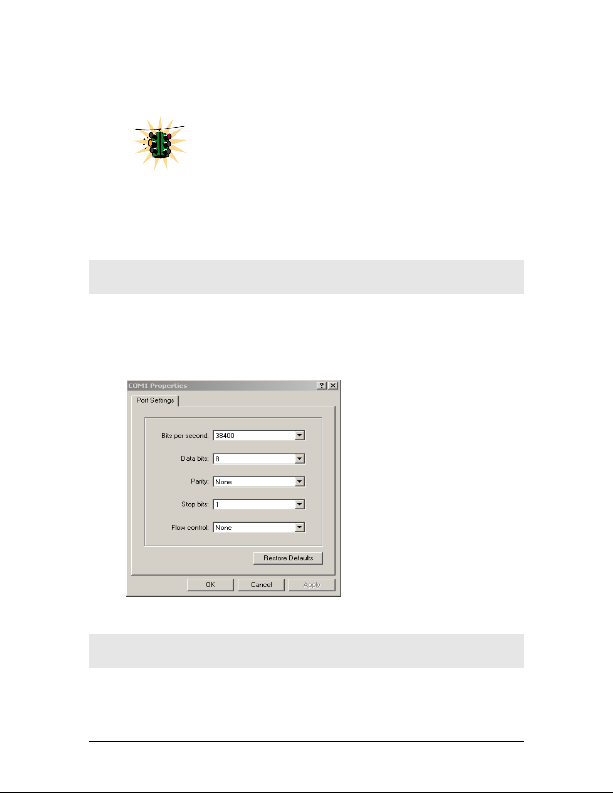
Console setup
Connect the console port on the switch to the serial port on the computer using the
serial cable listed above. The settings for the HyperTerminal software emulating a
VT100 are shown in Figure 1 below. Make sure the serial parameters are set as
shown (or bps = 38400, data bits=8, parity=none, stop bits=1, flow control=none).
FIGURE 1 - HyperTerminal screen showing the serial settings
Console screen
Once the console cable is connected to the PC and the software configured, MNS6K legal disclaimers and other text scrolls by on the screen.
24
Page 26

MAGNUM 6K SWITCHES, MNS-6K USER GUIDE
The switch has three modes of operation – Operator (least privilege), Manager and
Configuration. The prompts for the switches change as the switch changes modes
from Operator to Manager to Configuration. The prompts are shown in Figure 2
below, with a brief explanation of what the different prompts indicate.
Magnum6K> Operator Level – for running operations queries
Magnum6K# Manager Level – for setting and reviewing commands
Magnum6K## Configuration Level – for changing the switch parameter values
FIGURE 2 - Prompt indicating the switch model number as well as mode of operation – note the
commands to switch between the levels is not shown here.
The prompt can be changed by the user. See the Chapter on Miscellaneous
Commands, sub section Prompt for more details. This manual was documented on a
Magnum 6K25 switch, and for clarity, the prompt shown in the manual will be
Magnum6K25
For additional information on default users, user levels and
j
more, see User Management in this guide.
Logging in for the first time
For the first time, use the default user name and passwords assigned by GarrettCom
for the Magnum 6K family of switches. They are:
Username – manager Password – manager
Username – operator Password – operator
We recommend you login as manager for the first time to set up the IP address as
well as change user passwords or create new users.
Setting the IP parameters
To setup the switch, the IP address and other relevant TCP/IP parameters have to
be specified. A new GarrettCom Magnum switch looks for a DHCP or a BootP
server. If a DHCP or a BootP server is present, the switch will be assigned an IP
address from those servers. Failing to find these servers, the IP address is
automatically assigned to 192.168.1.2 with a netmask of 255.255.255.0.
25
Page 27

MAGNUM 6K SWITCHES, MNS-6K USER GUIDE
Should a situation arise when there are multiple new switches powered up at the
same time, there could be a situation of duplicate IP addresses. In this situation, only
one Magnum switch will be assigned the IP address of 192.168.1.2 and netmask of
255.255.255.0. The other switches will not be assigned an IP address till the static IP
address of 192.168.1.2 is freed up or reassigned.
To change the IP address, please ensure that the IP address to be assigned to the
switch is known or contact your system/network administrator to get the IP address
information. Follow the steps listed below to configure the IP address manually.
• Ensure the power is off
• Follow the steps described above
for connecting the console cable and setting
the console software
• Power on the switch
• Once the login prompt appears, login as manager using default password
(manager)
• Configure the IP address, network mask and default gateway as per the IP
addressing scheme for your network
• Set the Manager Password (recommended–refer to next section)
• Save the settings (without saving, the changes made will be lost)
• Power off the switch (or a software reboot as discussed below)
• Power on the switch – login with the new login name and password
• From the PC (or from the switch) ping the IP address specified for the switch to
ensure connectivity
• From the switch ping the default gateway specified (ensure you are connected to
the network to check for connectivity) to ensure network connectivity
Syntax ipconfig [ip=<ip-address>] [mask=<subnet-mask>]
[dgw=<gateway>] [add|del]
Magnum6K25# ipconfig ip=192.168.1.150 mask=255.255.255.0
dgw=192.168.1.10
Magnum6K25# save
FIGURE 3 - Setting IP address on the switch
This document assumes the reader is familiar with IP
addressing schemes as well as how net mask is used and how
default gateways and routers are used in a network.
26
Page 28

MAGNUM 6K SWITCHES, MNS-6K USER GUIDE
Reboot gives an opportunity to save the configuration prior to shutdown. For a
reboot – simply type in the command “reboot”. (Note – even though the passwords
are not changed, they can be changed later.)
Magnum6K25# reboot
Proceed on rebooting the switch? [ 'Y' or 'N' ] Y
Do you wish to save current configuration? [ 'Y' or 'N' ] Y
Magnum6K25#
FIGURE 4 - Rebooting the switch
MNS-6K forces an answer the prompts with a “Y” or a “N” to prevent accidental
keystroke errors and loss of work.
The parameters can be viewed at any time by using the ‘show’ command. The show
command will be covered in more detail later in various sections throughout the
document.
Magnum6K25# show setup
Version : Magnum 6K25 build 3.7.1 Sep 27 2007 16:41:37
MAC Address : 00:20:08:03:05:09
IP Address : 192.168.5.5
Subnet Mask : 255.255.255.0
Gateway Address : 192.168.5.1
CLI Mode : Manager
System Name : Magnum 6K25
System Description : 25 Port Modular Ethernet Switch
System Contact : support@garrettcom.com
System Location : Fremont, CA
System ObjectId : 1.3.6.1.4.1.553.12.6
System Serial No : 43576812
Original Factory Config Code : 6K25-8TP
Magnum6K25# show sysconfig
System Name : Magnum6K25
System Contact : support@garrettcom.com
System Location : HO, Fremont, CA
Boot Mode : manual
Inactivity Timeout(min) : 10
Address Age Interval(min) : 300
Inbound Telnet Enabled : Yes
Web Agent Enabled : Yes
Time Zone : GMT-08hours:00minutes
Day Light Time Rule : USA
System UpTime : 36 Days 7 Hours 49 Mins 48 Secs
Magnum6K25#
FIGURE 5 - Viewing the basic setup parameters. You can use ‘show setup’ or ‘show sysconfig’ to
view setup parameters
27
Page 29

MAGNUM 6K SWITCHES, MNS-6K USER GUIDE
Some of the parameters in the Magnum 6K family of switches are shown above. The
list of parameters below indicates some of the key parameters on the switch and the
recommendations for changing them (or optionally keeping them the same).
Privilege levels
Two privilege levels are available - Manager and Operator. Operator is at privilege
level 1 and the Manager is at privilege level 2 (the privilege increases with the levels).
For example, to set up a user for basic monitoring capabilities use lower number or
operator level privilege (Level 1)
The Manager level provides all Operator level privileges plus the ability to
perform system-level actions and configuration commands. To select this level, enter
the ‘enable <user-name>’ command at the Operator level prompt and enter the
Manager password, when prompted.
Syntax enable <user-name>
For example, switching from an Operator level to manager level, using the ‘enable’
command is shown below in Figure 6
Magnum6K25> enable manager
Password: *******
Magnum6K25#
FIGURE 6 - Switching users and privilege levels. Note the prompt changes with the new privilege
level.
Operator Privileges
Operator privileges allow views of the current configurations but do not allow
changes to the configuration. A ">" character delimits the Operator-level prompt.
Manager Privileges
Manager privileges allow configuration changes. The changes can be done at the
manager prompt or for global configuration as well as specific configuration. A “#”
character delimits any Manager prompt.
User management
A maximum of five users can be added per switch. Users can be added, deleted or
changed from a manager level account. There can be more than one manager
account, subject to the maximum number of users on the switch being restricted to
five.
28
Page 30

MAGNUM 6K SWITCHES, MNS-6K USER GUIDE
Add User
To add a user, use the command “add” as shown below. The user name has to be a
unique name and can be up to 24 characters long. The password is recommended to be at
least 8 characters long with a mix of upper case, lower case, numbers and special
characters.
Syntax add user=<name> level=<number>
Magnum6K25# user
Magnum6K25(user)## add user=peter level=2
Enter User Password:******
Confirm New Password:******
Magnum6K25(user)##
FIGURE 7 - Adding a user with Manager level privilege
In this example, user ‘peter’ was added with Manager privilege.
Delete User
Syntax delete user=<name>
Magnum6K25(user)##delete user=peter
Confirm User Deletion(Y/N): Y
User successfully deleted
Magnum6K25(user)##
FIGURE 8 - Deleting a user
In this example, user ‘peter’ was deleted.
Modify Pass word
Syntax passwd user=<name>
Magnum6K25(user)## passwd user=peter
Enter New Password:******
Confirm New Password :******
Password has been modified successfully
Magnum6K25(user)##
FIGURE 9 - Changing the password for a specific user
In this example, password for ‘peter’ was modified.
Modify the Privilege Level
Syntax chlevel user=<name> level=<number>
29
Page 31

MAGNUM 6K SWITCHES, MNS-6K USER GUIDE
Magnum6K25(user)## chlevel user=peter level=1
Access Permission Modified
Magnum6K25(user)##
FIGURE 10 - Changing the privilege levels for a user
In this example, user ‘peter’ was modified to Operator privileges.
Modify Access Privileges for a user
Syntax useraccess user=<name> service=<telnet|web> <enable|disable>
Where
user=<name> specifies the user id
service=<telnet|web> specifies which service (telnet or web) the user has access
to
<enable|disable> specifies whether the services are allowed or not allowed.
Magnum6K25# user
Magnum6K25(user)## add user=peter level=2
Enter User Password :*****
Confirm New Password :*****
Magnum6K25(user)## useraccess user=peter service=telnet disable
Telnet Access Disabled.
FIGURE 11 – Creating user access privileges
After this command, user Peter will not have telnet access to the switch. User Peter
only has console access or SWM access.
The user “peter” has to be added before this command can be
successfully executed.
30
Page 32

MAGNUM 6K SWITCHES, MNS-6K USER GUIDE
Help
Typing the ‘help’ command lists the commands you can execute at the current privilege
level. For example, typing ‘help’ at the Operator level shows
Magnum6K25> help
logout ping set
terminal telnet walkmib
Contextless Commands:
! ? clear
enable exit help
show whoami
alarm
Magnum6K25>
FIGURE 12 - Help command
Displaying Help for an Individual Command
Help for any command that is available at the current context level can be viewed by
typing help followed by enough of the command string to identify the command.
Syntax help
<command string>
For example, to list the Help for the ‘set time’ command
Magnum6K25# help set time
set time : Sets the device Time
Usage
set time hour=<0-23> min=<0-59> sec=<0-59> [zone=GMT[+/-]hh:mm]
Magnum6K25#
FIGURE 13 - Help for a specific command
Viewing options for a command
The options for a specific command can be displayed by typing the command and
pressing enter.
Syntax command
Magnum6K25# show <Enter>
<Enter>
31
Page 33

MAGNUM 6K SWITCHES, MNS-6K USER GUIDE
Usage
show active-stp
show active-snmp
show active-vlan
show address-table
show age
show alarm
show arp
show auth <config|ports>
show backpressure
show bootmode
--more--
FIGURE 14 - Options for the ‘show’ command
Context help
Other ways to display help, specifically, with reference to a command or a set of
commands, use the TAB key.
Syntax <TAB>
Syntax <Command string> <TAB>
Syntax <First character of the command> <TAB>
For example, following the syntax listed above, the <TAB> key will list the available
commands in the particular privilege level:
Magnum6K25> <TAB>
?
alarm
clear
enable
exit
help
logout
ping
set
show
telnet
terminal
walkmib
whoami
Magnum6K25>
FIGURE 15 - Listing commands available (at the operator level)
OR
Magnum6K25> s <TAB>
set
show
Magnum6K25>
FIGURE 16 - Listing commands starting with a specific character
32
Page 34

MAGNUM 6K SWITCHES, MNS-6K USER GUIDE
OR
Magnum6K25> se<TAB>
password
timeout
vlan
Magnum6K25> set
FIGURE 17 - Listing commands options – note the command was not completed and the TAB key
completed the command.
Exiting
To exit from the CLI interface and terminate the console session use the ‘logout’
command. The logout command will prompt you to ensure that the logout was not
mistakenly typed.
Syntax logout
Magnum6K25# logout
Logging out from the current session...[ 'Y' or 'N'] Y
Connection to the host lost
FIGURE 18 – logout command
List of commands in this chapter
Syntax ipconfig [ip=<ip-address>] [mask=<subnet-mask>] [dgw=<gateway>]
[add|del] – to set IP address on the switch
Syntax save – save changes made to the configuration
Syntax reboot – restart the switch – same effect as physically turning off the power
Syntax show setup – show setup parameters
Syntax show config – show setup parameters configured
Syntax enable <user-name> - changing the privilege level
Syntax add user=<name> level=<number> - adding a user
Syntax delete user=<name> - deleting a user
33
Page 35

MAGNUM 6K SWITCHES, MNS-6K USER GUIDE
Syntax passwd user=<name> - changing a password for a user
Syntax chlevel user=<name> level=<number> - changing the user privilege level
Syntax help
<command string>
- help for a specific command
Syntax command
<Enter>
- options for a command
Syntax <TAB> - listing all commands available at the privilege level
Syntax <command string> <TAB> - options for a command
Syntax <first character of the command> <TAB> - listing commands starting with the character
Syntax logout – logout from the CLI session
Syntax useraccess user=<name> service=<telnet|web> <enable|disable>
34
Page 36

3 – IP Address and System
Information
First simple steps to follow…
his section explains how the Magnum 6K family of switches can be setup using other
automatic methods such as bootp and DHCP. Besides this, other parameters required for
T
proper operation of the switch in a network are discussed.
Chapter
3
IP Addressing
j
It is assumed that the user has familiarity with IP addresses, classes
of IP addresses and related netmask schemes (e.g. class A, Class B
and Class C addressing).
Importance of an IP address
Without an IP address, the switch will operate as a standalone Layer 2 switch. Without an IP
address, you cannot
• Use the web interface to manage the switch
• Use telnet to access the CLI
• Use any SNMP Network Management software to manage the switch
• Use NTP protocol or an NTP server to synchronize the time on the switch
• Use TFTP or FTP to download the configurations or upload software updates
• Run ping tests to test connectivity
To set the IP address, please refer to the section in Chapter 2 – Setting IP Parameters.
Once the IP address is set, the CLI can be accessed via the telnet programs as
well as the console interface. From now on – all commands discussed are
accessible from the CLI – irrespective of the access methods – serial port or in
band using telnet.
35
Page 37

MAGNUM 6K SWITCHES, MNS-6K USER GUIDE
To verify the IP address settings, the ‘show ipconfig’ command can be used.
Magnum6K25> show ipconfig
IP Address : 192.168.1.150
Subnet Mask : 255.255.255.0
Default Gateway : 192.168.1.10
Magnum6K25>
FIGURE 19 - Checking the IP settings
Besides manually assigning IP addresses, there are other means to assign an IP address
automatically. The two most common procedures are using DHCP and bootp.
DHCP and bootp
j
networking devices such as switches, routers, VoIP phones and more. Both of them can
work independent of each other. Both of them are widely used in the industry. It’s best to
check with your network administrator as to what protocol to use and what the related
parameters are. DHCP and bootp require respective services on the network. DHCP and
bootp can automatically assign an IP address. It is assumed that the reader knows how to
setup the necessary bootp parameters (usually specified on Linux/UNIX systems in
/etc/boopttab1).
DHCP is commonly used for setting up addresses for computers,
users and other user devices on the network. bootp is the older
cousin of DHCP and is used for setting up IP addresses of
Bootp Database
Bootp keeps a record of systems supported in a database – a simple text file. On most
systems, the bootp service is not started as a default and has to be enabled. A sample entry
by which the bootp software will look up the database and update the IP address and
subnet mask of the switch would be as follows
M6k25switch:\
ht=ether:\
ha=002006250065:\
ip=192.168.1.88:\
sm=255.255.255.0:\
gw=192.168.1.1:\
hn:\
vm=rfc1048
where
M6k25switch: is a user-defined symbolic name for the switch
1
Note – on Windows systems – the location of the file will vary depending on which software is being used.
36
Page 38

MAGNUM 6K SWITCHES, MNS-6K USER GUIDE
ht: is the “hardware type”. For the Magnum 6K family of switches, set this to ether (for
Ethernet).
This tag must precede the “
ha” tag.
ha: is the “hardware address”. Use the switch’s 12-digit MAC address
ip: is the IP address to be assigned to the switch
sm: is the subnet mask of the subnet in which the switch is installed
Configuring Auto/DHCP/Bootp/Manual
By default, the switch is configured for ‘auto’. As describer earlier in Chapter 2, in the
auto mode, the switch will first look for a DHCP server. If a DHCP server is not found, it
will then look for a BootP server. If that server is not found, the switch will first inspect to
see if the IP address 192.168.1.2 with a netmask of 255.255.255.0 is free. If the IP address
is free, MNS-6K will assign the switch that IP address. If the address is not free, MNS-6K
will poll the network for DHCP server then BootP server then check if the IP address
192.68.1.2 is freed up. This mode of assigning the IP address can be changed by using the
‘set bootmode’ command.
Syntax set bootmode type=<dhcp|bootp|manual|auto>
[bootimg=<enable|disable>] [bootcfg=[<enable|disable>] – assign the boot mode
for the switch
Where
<dhcp|bootp|manual|auto> - where
dhcp – look only for DHCP servers on the network for the IP address. Disable
bootp or other modes
bootp – look only for bootp servers on the network. Disable dhcp or other mode
manual – do not set the IP address automatically
auto - the switch will first look for a DHCP server. If a DHCP server is not found,
it will then look for a BootP server. If that server is not found, the switch will
check to see if the switch had a pre-configured IP address. If it did, the switch
would be assigned that IP address. If the switch did not have a pre-configured
IP address, it would inspect if the IP address 192.168.1.2 with a netmask of
255.255.255.0 is free. If the IP address is free, MNS-6K will assign the switch
that IP address. If the address is not free, MNS-6K will poll the network for
DHCP server then BootP server then check if the IP address 192.68.1.2 is freed
up
bootimg=<enable|disable> - valid with type=bootp only. This option allows the
switch to load the image file from the BootP server. This is useful when a new switch
is put on a network and the IT policies are set to load only a specific MNS-6Kimage
which is supported and tested by IT personnel.
bootcfg=<enable|disable> - valiad with type=bootp only. This option allows the
switch to load the configuration file from the BootP server. This is useful when a new
37
Page 39

MAGNUM 6K SWITCHES, MNS-6K USER GUIDE
switch is put on a network and the specific configurations are loaded from a
centralized BootP server
Magnum6K25# set bootmode type=dhcp
Save Configuration and Restart System
Magnum6K25# set bootmode type=auto
Save Configuration and Restart System
Magnum6K25# set bootmode type=bootp bootimg=enable bootcfg=disable
Network application image download is enabled.
Network application config download is disabled.
Save Configuration and Restart System
Magnum6K25#
FIGURE 20 - Changing the boot mode of the switch
Using T elnet
By default, the telnet client is enabled on the GarrettCom Magnum 6K family of switches.
MNS-6K supports five simultaneous sessions on a switch – four telnet sessions and one
console session. This allows many users to view, discuss or edit changes to the MNS-6K.
This also becomes useful as two remote people want to view the commands and other
settings on the switch. The telnet client can be disabled by using the “telnet disable”
command. Telnet can also be disabled for a specific user by using the “useraccess”
command discussed in Chapter 2.
Multiple telnet sessions started from the CLI interface or the command line are serviced
by MNS-6K in a round robin fashion – i.e. one session after another. If one telnet session
started from MNS-6K interface is downloading a file, the other windows will not be
serviced till the file transfer is completed.
Syntax telnet <enable|disable>
Magnum6K25# configure access
Magnum6K25(access)## telnet enable
Access to Telnet already enabled
Magnum6K25(access)## exit
Magnum6K25#
FIGURE 21 - Changing telnet access – note in this case, the enable command was repeated without
any effect to the switch
The ‘show console’ command can show the status of the telnet client as well as other
console parameters.
38
Page 40

MAGNUM 6K SWITCHES, MNS-6K USER GUIDE
Magnum6K25# show console
Console/Serial Link
Inbound Telnet Enabled : Yes
Outbound Telnet Enabled : Yes
Web Console Enabled : Yes
SNMP Enabled : Yes
Terminal Type : VT100
Screen Refresh Interval (sec) : 3
Baud Rate : 38400
Flow Control : None
Session Inactivity Time (min) : 10
Magnum6K25#
FIGURE 22 - Reviewing the console parameters – note telnet is enabled
Users can telnet to a remote host from the Magnum 6K family of switches.
Syntax telnet <ipaddress> [port=<port number>]
The default port for telnet is 23.
Magnum6K25# show ipconfig
IP Address : 192.168.1.11
Subnet Mask : 255.255.255.0
Gateway Address : 192.168.1.1
Magnum6K25# telnet 192.168.1.1 port=2097
FIGURE 23 - Example of a telnet session
While MNS-6K times out an idle telnet session, it may be useful to see who is currently connected to
the switch. It may also be useful for a person to remotely terminate a telnet session. To facilitate this,
MNS-6K supports two commands
Syntax show session
Syntax kill session id=<session> - terminate a telnet session
39
Page 41

MAGNUM 6K SWITCHES, MNS-6K USER GUIDE
Magnum6K25# user
Magnum6K25(user)## useraccess user=peter service=telnet enable
Telnet Access Enabled.
Magnum6K25(user)## exit
Magnum6K25# show session
Current Sessions:
SL # Session Id Connection User Name User Mode
1 1 163.10.10.14 manager Manager
2 2 163.11.11.15 peter Manager
3 3 163.12.12.16 operator Operator
Magnum6K25# kill session id=3
Session Terminated.
Magnum6K25#
FIGURE 24 – managing and viewing multiple telnet sessions
In the above example, the user with user-id peter is given telnet access (which was disabled earlier in
Chapter 2). Then multiple users telnet into the switch. This is shown using the “show session”
command. The user operator session is then terminated using the “kill session” command.
The default port – port 23 is used for telnet.
A maximum of four simultaneous telnet sessions are allowed at any time on the
switch. The commands in these telnet windows are executed in a round robin – i.e.
if one window takes a long time to finish a command, the other windows may
encounter a delay before the command is completed. For example, if one window
is executing a file download, the other windows will not be able to execute the
command before the file transfer is completed. Another example, if a outbound
telnet session is started from the switch (through a telnet window) then the other
windows will not be able to execute a command till the telnet session is completed.
Setting serial port parameters
To be compliant with IT or other policies the console parameters can be changed from the CLI
interface. This is best done by setting the IP address and then telnet over to the switch. Once
connected using telnet, the serial parameters can be changed. If you are using the serial port,
remember to set the VT-100 emulation software properties to match the new settings.
Syntax set serial [baud=<rate>] [data=<5|6|7|8>] [parity=<none|odd|even>]
[stop=<1|1.5|2>] [flowctrl=<none|xonxoff>]
Where <rate> = standard supported baud rates
40
Page 42

MAGNUM 6K SWITCHES, MNS-6K USER GUIDE
Warning – changing these parameters through the serial port will cause loss
of connectivity – the parameters of the terminals software (e.g. Hyper
Terminal etc.) will also have to be changed to match the new settings.
To see the current settings of the serial port, use the ‘show serial’ command.
Magnum6K25# show serial
Baud Rate : 38400
Data : 8
Parity : No Parity
Stop : 1
Flow Control : None
FIGURE 25 - Querying the serial port settings
System parameters
The system parameters can be queried and changed. To query the system parameters, two
commands are used frequently. They are ‘show sysconfig’ and ‘show setup’. Both the
commands are shown below.
Magnum6K25# show setup
Version : Magnum 6K25 build 3.7.1 Sep 27 2007 16:41:37
MAC Address : 00:20:08:03:05:09
IP Address : 192.168.5.5
Subnet Mask : 255.255.255.0
Gateway Address : 192.168.5.1
CLI Mode : Manager
System Name : Magnum 6K25
System Description : 25 Port Modular Ethernet Switch
System Contact : support@garrettcom.com
System Location : Fremont, CA
System ObjectId : 1.3.6.1.4.1.553.12.6
System Seriial No. : 43576812
Original Factory Config Code : 6K25-8TP
Magnum6K25#
FIGURE 26 - System parameters using the show setup command. Most parameters here cannot be
changed
41
Page 43

MAGNUM 6K SWITCHES, MNS-6K USER GUIDE
Magnum6K25# show sysconfig
System Name : Magnum6K25
System Contact : support@garrettcom.com
System Location : HO, Fremont, CA
Boot Mode : manual
Inactivity Timeout(min) : 10
Address Age Interval(min) : 300
Inbound Telnet Enabled : Yes
Web Agent Enabled : Yes
Time Zone : GMT-08hours:00minutes
Day Light Time Rule : USA
System UpTime : 7 Days 12 Hours 30 Mins 46 Secs
Magnum6K25#
FIGURE 27 - System parameters using the show sysconfig command. Most parameters here can be
changed.
System variables can be changed. Below is a list of system variables which GarrettCom
recommends changing.
System Name: Using a unique name helps you to identify individual devices in a
network.
System Contact and System Information: This is helpful for identifying the
administrator responsible for the switch and for identifying the locations of individual
switches.
To set these variables, change the mode to be SNMP configuration mode from the
manager mode.
Syntax snmp
Syntax setvar [sysname|syscontact|syslocation]=<string> where string is a character
string, maximum 24 characters long
Magnum6K25# snmp
Magnum6K25(snmp)## setvar ?
setvar : Configures system name, contact or location
Usage:
setvar [sysname|syscontact|syslocation]=<string>
Magnum6K25(snmp)## setvar syslocation=Fremont
System variable(s) set successfully
Magnum6K25(snmp)## exit
Magnum6K25#
FIGURE 28 - Setting the system name, system location and system contact information
42
Page 44

MAGNUM 6K SWITCHES, MNS-6K USER GUIDE
Date and time
It may be necessary to set the day, time or the time zone manually. This can be done by
using the ‘set’ command with the necessary date and time options. These are listed below:
Syntax set timezone GMT=[+ or -] hour=<0-14> min=<0-59>
Syntax set date year=<2001-2035> month=<1-12> day=<1-31>
[format=<mmddyyyy|ddmmyyyy|yyyymmdd>]
Syntax set time hour=<0-23> min=<0-59> sec=<0-59> [zone=GMT[+/-]hh:mm]
Thus to set the time to be 08:10 am in the -8 hours from GMT (PST or time zone on west
coast of USA) and to set the date to be 15 October 2003, the following set of commands
are used.
Magnum6K25# set time hour=8 min=30 sec=0 zone=GMT-8:00
success in setting device time
Magnum6K25# show time
Time : 8:30:04
Magnum6K25# show timezone
Timezone : GMT-08hours:00minutes
Magnum6K25# set date year=2003 month=10 day=15
Success in setting device date
Magnum6K25# show date
System Date : Wednesday 10-15-2003 (in mm-dd-yyyy format)
Magnum6K25#
FIGURE 29 - Setting the system date, time and time zone
Rebooting the switch resets the time to the default. Synchronizing with the time server
resets the time. Other relevant date and time commands are:
Syntax set timeformat format=<12|24>
Syntax set daylight country=< country name>
Magnum6K25# set daylight ?
set daylight : Sets the day light location
Usage
set daylight country=<name>
Magnum6K25# set daylight country=USA
Success in setting daylight savings to the given location/country USA
Magnum6K25# show daylight
43
Page 45

MAGNUM 6K SWITCHES, MNS-6K USER GUIDE
Daylight savings location name : USA
Magnum6K25#
FIGURE 30 - Setting the system daylight saving time
See Appendix 3 for additional information on Daylight Savings Time. The lists of countries for the time
zone are
Australia, Belgium, Canada, Chile, Cuba, Egypt, France, Finland, Germany, Greece, Iraq, Italy, London,
Namibia, Portugal, Russia, Spain, Sweden, Switzerland, Syria, USA
Network time
Many networks synchronize the time using a Network time server. The network time
server provides time to the different machines using the Simple Network Time Protocol
(SNTP). To specify the SNTP server, one has to
1) Set the IP parameters on the switch
2) Define the SNTP parameters
To set the SNTP parameter, enter the SNTP configuration mode from the manager. The
‘setsntp, sync, sntp’ commands can then be used to setup the time synchronization
automatically from the SNTP server. Note it is not sufficient to setup the SNTP variables.
Make sure to setup the synchronization frequency as well as enable SNTP. The list of
relevant commands is listed below.
Syntax setsntp server = <ipaddress> timeout = <1-10> retry = <1-3>
Syntax sync [hour=<0-24>] [min=<0-59>] (default = 24 hours)
The time zone and daylight savings time information have to be set
for SNTP server to set the proper time
Syntax sntp [enable|disable]
2
For example, to set the SNTP server to be 204.65.129.201
and a number of retries set to 3 times); allowing the synchronization to be ever 5 hours, the
following commands are used
(with a time out of 3 seconds
2
There are number of public NTP servers. Search on the internet using ‘NTP Servers’ yields the necessary server IP addresses.
44
Page 46

MAGNUM 6K SWITCHES, MNS-6K USER GUIDE
y
Magnum6K25# sntp
Magnum6K25(sntp)## setsntp server=204.65.129.201 timeout=3 retry=3
SNTP server is added to SNTP server database
Magnum6K25(sntp)## sync hour=5
Magnum6K25(sntp)## sntp enable
SNTP is already enabled.
Magnum6K25(sntp)## exit
Magnum6K25(sntp)#
Do not forget to enable sntp
for time s
nchronization.
FIGURE 31 - Setting up SNTP services
Saving and loading configuration
After configuration changes are made, all the changes are automatically registered but not
saved i.e. the effect of the change is immediate, however, if power fails, the changes are
not saved and restored, unless the changed are saved using the save command. It is also a
good practice to save the configuration on another server on the network using the tftp or
ftp protocols. Once the configuration is saved – the saved configuration can be loaded to
restore back the settings. At this time the configuration parameter saved or loaded are not
in a human readable format. The commands for saving and loading configurations on the
network are:
Syntax saveconf mode=<serial|tftp|ftp> [<ipaddress>] [file=<name>]
Syntax loadconf mode=<serial|tftp|ftp> [<ipaddress>] [file=<name>]
Make sure the machine specified by the IP address has the necessary services running on
it. For serial connections, x-modem or other alternative methods can be used. File name
in many situations has to be a unique file name as over-writing files is not permitted by
most ftp and tftp servers (or services). Only alpha-numeric characters are allowed in the
file name – special characters like !@#$%&*(\|){/};[,’]” (or other control characters e.g.
^G) are not allowed
Magnum6K25# saveconf mode=tftp 192.168.10.1 file=mag6Kmain
Do you wish to upload the configuration? [ 'Y' or 'N'] Y
FIGURE 32 - Saving the configuration on a tftp server
The “saveconf” and “loadconf” commands are used often to update new software to
the Magnum 6K family of switches. These commands will be obsoleted in the next release
and replaced with the “ftp” or “tftp” or “xmodem” commands listed below. It is advised
to start using these commands instead of “saveconf” and “loadconf”. Before the
45
Page 47

MAGNUM 6K SWITCHES, MNS-6K USER GUIDE
software is updated, it is advised to save the configurations. The re-loading of the
configuration is not usually necessary; however, in certain situations it maybe needed and
it is advised to save configurations before a software update. The ‘loadconf’ command
requires a reboot for the new configuration to be active. Without a reboot the older
configuration is used by the Magnum 6K family of switches. When Reboot is selected,
the user is prompted: ‘Reboot Y/N’. Select ‘Y’, the prompt is then: ‘Save Current
Configuration?’ You must select ‘No’.
Along with the ftp command listed below, MNS-6K also supports normal ftp as well as
passive ftp. Passive FTP is used by many companies today to work with firewall policies
and other security policies set by companies. The commands for setting the type of ftp
are:
Syntax set ftp mode=<normal|passive> - set the ftp mode of operation3
Syntax show ftp- display the current ftp operation mode
With MNS-6K additional capabilities have been added to save and load configurations.
The commands are:
Syntax ftp <get|put|list|del> [type=<app|config|oldconf|script|hosts|log>]
[host=<hostname>] [ip=<ipaddress>] [file=<filename>] [user=<user>]
[pass=<password>] – upload and download information using ftp command
Where
<get|put|list|del> - different ftp operations
[type=<app|config|oldconf|script|hosts|log>] – optional type field. This
is useful to specify whether a log file or host file is uploaded or downloaded.
This can also perform the task of exporting a configuration file or uploading a
new image to the switch
[host=<hostname>] [ip=<ipaddress>] [file=<filename>] [user=<user>]
[pass=<password>] – parameters associated with ftp server for proper
communications with the server
Syntax tftp <get|put> [type=<app|config|oldconf|script|hosts|log>]
[host=<hostname>] [ip=<ipaddress>] [file=<filename>] – upload and
download information using tftp command
Where
<get|put> - different tftp operations – get a file from the server or put the
information on the server
3
FTP uses a set of separate ports for the data stream and command stream. This causes problems in security conscious companies
who prefer that the client initiate the file transfer as well as the stream for the commands. To accommodate that, ftp added the
capability called “passive ftp” in which the client initiating the connection initiates both the data and command connection request.
Most companies prefer passive ftp and GarrettCom MNS-6K provides means to operate in those environments.
46
Page 48

MAGNUM 6K SWITCHES, MNS-6K USER GUIDE
[type=<app|config|oldconf|script|hosts|log>] – optional type field. This
is useful to specify whether a log file or host file is uploaded or downloaded.
This can also perform the task of exporting a configuration file or uploading a
new image to the switch
[host=<hostname>] [ip=<ipaddress>] [file=<filename>] – parameters
associated with tftp server for proper communications with the server
Syntax xmodem <get|put> [type=<app|config|oldconf|script|hosts|log>] –
upload and download information using xmodem command and console connection
Where
<get|put> - different xmodem file transfer operations – get a file from the server
or put the information on the server
[type=<app|config|oldconf|script|hosts|log>] – optional type field. This
is useful to specify whether a log file or host file is uploaded or downloaded.
This can also perform the task of exporting a configuration file or uploading a
new image to the switch
The details are conceptually explained in the figure below.
app
MNS-6K
MNS-6K
image
image
CLI
CLI
commands
commands
ftp
ftp
or
or
tftp Server
tftp Server
xmodem
xmodem
connection
connection
F
IGURE 33 – Based on the ftp or tftp or xmodem commands – the MNS-6K based switch can upload
or download different types of files and images .Other files such as log files, hosts file can also be saved or
loaded onto a switch
or
or
Configuration
Configuration
parameters
parameters
app
script
script
config
config
47
Page 49

MAGNUM 6K SWITCHES, MNS-6K USER GUIDE
Prior to Release 3.2, the configuration was saved only as a binary object (file). With
Release 3.2 and beyond, the configuration can be saved in the older format – binary
object or in a newer format as an ASCII (readable) file. The new format is preferred by
GarrettCom and GarrettCom recommends all configuration files be saved in the new
format. GarrettCom recommends saving the configuration in the old format only if
there are multiple Magnum 6K family of switches on the network and they all run
different versions of MNS-6K. GarrettCom recommends to upgrade all switches to the
most current release of MNS-6K.
Config files
As shown in the figure above, MNS-6K can now use the ftp, tftp or xmodem commands to
upload and download information to the server running the proper services. One useful capability
provided in MNS-6K is the capability to export the CLI commands (as described in this manual)
used to configure the switch. To do that, for example, using the tftp command, the sequence of
commands are shown below
Magnum 6K25# show ftp
Current FTP Mode: NORMAL
Magnum 6K25# set ftp mode=passive
FTP Set to Passive Mode
Magnum 6K25# show ftp
Current FTP Mode: PASSIVE
Magnum 6K25# set ftp mode=normal
FTP Set to Normal Mode
Magnum 6K25# show ftp
Current FTP Mode: NORMAL
Magnum6K25# ftp put type=config ip=192.168.5.2 file=config
Do you wish to export configuration file? [ 'Y' or 'N'] Y
Successfully exported the configuration
Magnum6K25#
FIGURE 34 – commands to save the configuration using ftp. Similar options will be specified using tftp etc.
When using the ftp command, use the host command discussed later in this section to define the ftp server
After saving the contents of the saved configuration file are as follows
################################################################
# Copyright (c) 2001-2005 GarrettCom, Inc All rights reserved.
# RESTRICTED RIGHTS
# ---------------------------------
# Use, duplication or disclosure is subject to U.S. Government
# restrictions as set forth in Sub-division (b)(3)(ii) of the
48
Page 50

MAGNUM 6K SWITCHES, MNS-6K USER GUIDE
# rights in Technical Data and Computer Software clause at
# 52.227-7013.
#
# This file is provided as a sample template to create a backup
# of Magnum 6K switch configurations. As such, this script
# provides insights into the configuration of Magnum 6K switch's
# settings. GarrettCom recommends that modifications of this
# file and the commands should be verified by the User in a
# test environment prior to use in a "live" production network.
# All modifications are made at the User's own risk and are
# subject to the limitations of the GarrettCom software End User
# License Agreement (EULA). Incorrect usage may result in
# network shutdown. GarrettCom is not liable for incidental or
# consequential damages due to improper use.
################################################################
#Magnum 6KQ build 3.7.1 Sep 27 2007 16:41:37
#Modules: 39 99 86 0
#Slot A: 4 Port TP-MDIX Module
#Slot B: 2 Port Fiber10 Module
#Slot C: 4 Port Fiber100 Module
#Slot D: 1 10/100/1000T 1 Giga SFP-1000
##########################################################
# System Manager - This area configures System related #
# information. #
##########################################################
set bootmode type=auto
set timeout=10
access
telnet enable
snmp enable
web enable
ssl enable
exit
##########################################################
# User Accounts - This area configures user accounts for #
# accessing this system. #
##########################################################
user
add user=manager level=2 pass=manager
useraccess user=manager service=telnet enable
useraccess user=manager service=web enable
useraccess user=manager service=acl enable
add user=operator level=1 pass=operator
##########################################################
<additional lines deleted for succinct viewing>
FIGURE 35 – Contents of the config file
Note 1 – the config file only allows certain portions of the file to be edited by a user.
Changing any other part of the file will not allow the file to be loaded as the CRC
49
Page 51

MAGNUM 6K SWITCHES, MNS-6K USER GUIDE
computed and stored in the file will not be matched. Should you want to edit, edit the System portion
of the file only. GarrettCom recommends editing the “script” file (see below)
Note 2 – File names cannot have special characters such as *#!@$^&* space and control characters.
To ease the process of uploading and executing a series of commands, the MNS-6K
commands are:
Syntax host <add|edit|del> name=<host-name> [ip=<ipaddress>] [user=<user>]
[pass=<password>] – create a host entry for accessing host. This is equivalent
to creating a host table on many systems. Maximum of 10 such entries are
allowed
Syntax show host – displays the host table entries
Magnum6K25# access
Magnum6K25(access)## host
Usage
host <add|edit|del> name=<host-name> [ip=<ipaddress>] [user=<user>] [pass=<password>]
Magnum6K25(access)## host add name=server ip=192.168.5.2
Host added successfully
Magnum6K25(access)## show host
No Host Name IP Address User Password
====================================================================
1 server 192.168.5.2 -- ******
2 -- -- -- - 3 -- -- -- - 4 -- -- -- - 5 -- -- -- - 6 -- -- -- - 7 -- -- -- - 8 -- -- -- - 9 -- -- -- - 10 -- -- -- --
Magnum 6K25(access)##
FIGURE 36 – Creating host entries on MNS-6K
Displaying configuration
To display the configuration or to view specific modules configured, the ‘show config’ command is
used as described below.
Syntax show config [module=<module-name>]
50
Page 52

MAGNUM 6K SWITCHES, MNS-6K USER GUIDE
Where module-name can be
Name Areas affected
system IP Configuration, Boot mode, Users settings (e.g.
login names, passwords)
event Event Log and Alarm settings
port Port settings, Broadcast Protection and QoS
settings
bridge Age time setting
stp STP, RSTP, S- Ring and LLL settings
ps Port Security settings
mirror Port Mirror settings
sntp SNTP settings
llan VLAN settings
gvrp GVRP settings
snmp SNMP settings
web Web and SSL/TLS settings
tacacs TACACS+ settings
auth 802.1x Settings
igmp IGMP Settings
smtp SMTP settings
If the module name is not specified the whole configuration is displayed.
Magnum6K25# show config
[HARDWARE]
type=Magnum6K25
slotB=8 Port TP Module
########################### ###### ######### ######### #######
# System Manager - This area configures System related #
# information. #
########################### ###### ######### ######### #######
[SYSTEM]
***Edit below this line only****
system_name=Main
system_contact=someone@joe.com
system_location=Sunnyvale, CA
boot_mode=manual
system_ip=192.168.1.15
system_subnet=0.0.0.0
system_gateway=192.168.1.11
idle_timeout=10
telnet_access=enable
snmp_access=enable
web_access=enable
--more—
51
Page 53

MAGNUM 6K SWITCHES, MNS-6K USER GUIDE
<additional lines deleted for succinct viewing>
FIGURE 37 – ‘
show config’
command output
Magnum6K25# show config module=snmp
[HARDWARE]
type=Magnum6K25
slotB=8 Port TP Module
########################### ###### ######### ######### #######
# Network Management - This area configures the S NMPv3 #
# agent. #
########################### ###### ######### ######### #######
[SNMP]
engineid=6K_v3Engine
defreadcomm=public
defwritecomm=private
deftrapcomm=public
authtrap=disable
com2sec_count=0
group_count=0
view_count=1
view1_name=all
view1_type=included
view1_subtree=.1
view1_mask=ff
--more—
<additional lines deleted for succinct viewing>
FIGURE 38 – displaying specific modules using the
‘show config’
command
Magnum6K25# show config module=snmp,system
[HARDWARE]
type=Magnum6K25
slotB=8 Port TP Module
########################### ###### ######### ######### #######
# System Manager - This area configures System related #
# information. #
########################### ###### ######### ######### #######
[SYSTEM]
***Edit below this line only****
system_name=Main
system_contact=someone@joe.com
system_location=Sunnyvale, CA
boot_mode=manual
system_ip=192.168.1.15
system_subnet=0.0.0.0
system_gateway=192.168.1.11
idle_timeout=10
telnet_access=enable
52
Page 54

MAGNUM 6K SWITCHES, MNS-6K USER GUIDE
snmp_access=enable
web_access=enable
--more—
<additional lines deleted for succinct viewing>
FIGURE 39 – displaying configuration for different modules. Note – multiple modules can be specified on the
command line
Erasing configuration
To erase the configuration and reset the configurations to factory default, you can use the
command ‘kill config’. This command is a “hidden command” i.e. the on-line help and other
help functions normally do not display this command. The ‘kill config’ command resets
everything to the factory default. The reset does not take place till the switch reboots.
It is recommended to save the configuration (using ‘saveconf’
command discussed above) before using the ‘kill config’ command.
The ‘kill config’ will also reset the IP address and all other parameters
as well unless the save option described below is used.
Syntax kill config [save=module-name] – resets the system configuration. The module-name
option does not reset the specific module parameters. The modules are listed below
The module-name can be
Name Areas affected
system IP Configuration, Boot mode, Users settings (e.g.
login names, passwords)
event Event Log and Alarm settings
port Port settings, Broadcast Protection and QoS
settings
bridge Age time setting
stp STP, RSTP, S- Ring and LLL settings
ps Port Security settings
mirror Port Mirror settings
sntp SNTP settings
llan VLAN settings
gvrp GVRP settings
snmp SNMP settings
web Web and SSL/TLS settings
53
Page 55

MAGNUM 6K SWITCHES, MNS-6K USER GUIDE
tacacs TACACS+ settings
auth 802.1x Settings
igmp IGMP Settings
smtp SMTP settings
If the module name is not specified the whole configuration is erased.
For example, ‘kill config save=system’ preserves the system IP address, netmask and
default gateway.
Magnum6K25# kill config save=system
Do you want to erase the configuration? [ 'Y' or 'N'] Y
Successfully erased configuration...Please reboot.
FIGURE 40 – Erasing configuration without erasing the IP address
Once the configuration is erased, please reboot the switch for the changes to take effect.
Displaying Serial Number
To display the serial number of the unit, use the command “show setup” as shown below. The
command also displays other information related to the switch.
Syntax show setup – display the setup, serial number, factory code information and more
Magnum 6K25# show setup
Version : Magnum 6K25 build 3.7.1 Sep 27 2007 16:41:37
MAC Address : 00:20:08:03:05:09
IP Address : 192.168.5.5
Subnet Mask : 255.255.255.0
Gateway Address : 192.168.5.1
CLI Mode : Manager
System Name : Magnum 6K25
System Description : 25 Port Modular Ethernet Switch
System Contact : support@garrettcom.com
System Location : Fremont, CA
System ObjectId : 1.3.6.1.4.1.553.12.6
System Seriial No. : 43576812
Original Factory Config Code : 6K25-8TP
Magnum 6K25#
FIGURE 41 – Display the serial number, factory code and other relevant setup information
54
Page 56

MAGNUM 6K SWITCHES, MNS-6K USER GUIDE
List of commands in this chapter
Syntax set bootmode type=<dhcp|bootp|manual|auto> [bootimg=<enable|disable>]
[bootcfg=[<enable|disable>] – assign the boot mode for the switch
Where
<dhcp|bootp|manual|auto> - where
dhcp – look only for DHCP servers on the network for the IP address. Disable
bootp or other modes
bootp – look only for bootp servers on the network. Disable dhcp or other mode
manual – do not set the IP address automatically
auto - the switch will first look for a DHCP server. If a DHCP server is not found,
it will then look for a BootP server. If that server is not found, the switch will
check to see if the switch had a pre-configured IP address. If it did, the switch
would be assigned that IP address. If the switch did not have a pre-configured
IP address, it would inspect if the IP address 192.168.1.2 with a netmask of
255.255.255.0 is free. If the IP address is free, MNS-6K will assign the switch
that IP address. If the address is not free, MNS-6K will poll the network for
DHCP server then BootP server then check if the IP address 192.68.1.2 is freed
up
bootimg=<enable|disable> - valiad with type=bootp only. Allows the switch to load
the image file from the BootP server. This is useful when a new switch is put on a
network and the IT policies are set to load only a specific MNS-6Kimage which is
supported and tested by IT personnel.
bootcfg=<enable|disable> - valiad with type=bootp only. Allows the switch to load
the configuration file from the BootP server. This is useful when a new switch is put
on a network and the specific configurations are loaded from a centralized BootP
server
Syntax telnet <enable|disable> - enables or disables telnet sessions
Syntax telnet <ipaddress> [port=<port number>] – telnet from the switch
Syntax set serial [baud=<rate>] [data=<5|6|7|8>] [parity=<none|odd|even>]
[stop=<1|1.5|2>] [flowctrl=<none|xonxoff>] – sets serial port parameters
Syntax snmp – enter the snmp configuration mode
Syntax setvar [sysname|syscontact|syslocation]=<string> - sets the system name, contact and
location information
Syntax set timezone GMT=[+ or -] hour=<0-14> min=<0-59> - sets the timezone
Syntax set date year=<2001-2035> month=<1-12> day=<1-31>
[format=<mmddyyyy|ddmmyyyy|yyyymmdd>] – sets the date and the format in which the
date is displayed
55
Page 57

MAGNUM 6K SWITCHES, MNS-6K USER GUIDE
Syntax set time hour=<0-23> min=<0-59> sec=<0-59> [zone=GMT[+/-]hh:mm] – sets the
time (as well as the timezone)
Syntax set timeformat format=<12|24> - sets the display time in the 12/24 hour mode
Syntax set daylight country=< country name> - sets the daylight saving time
Syntax setsntp server = <ipaddress> timeout = <1-10> retry = <1-3> - setup the SNTP server
Syntax sync [hour=<0-24>] [min=<0-59>] – setup the frequency at which the SNTP server is queried
Syntax sntp [enable|disable] – enables or disables the SNTP services
Syntax saveconf mode=<serial|tftp|ftp> [<ipaddress>] [file=<name>] – saves the
configuration on the network using tftp, ftp or serial protocols
Syntax loadconf mode=<serial|tftp|ftp> [<ipaddress>] [file=<name>] – loads the previously
saved configuration from the network using tftp, ftp or serial protocols
Syntax kill config [save=module_name] – resets the system configuration. The module_name option does not
reset the specific module parameters. The modules are system, event, port, bridge, stp, ps, mirror, sntp, vlan, gvrp
and snmp
Syntax show session – display telnet sessions active on the switch
Syntax kill session id=<session> - kill a specific telnet session
Syntax set ftp mode=<normal|passive> - set the ftp mode of operation
Syntax show ftp- display the current ftp operation mode
Syntax ftp <get|put|list|del> [type=<app|config|oldconf|script|hosts|log>]
[host=<hostname>] [ip=<ipaddress>] [file=<filename>] [user=<user>]
[pass=<password>] – upload and download information using ftp command
Where
<get|put|list|del> - different ftp operations
[type=<app|config|oldconf|script|hosts|log>] – optional type field. This is useful
to specify whether a log file or host file is uploaded or downloaded. This can also
perform the task of exporting a configuration file or uploading a new image to the
switch
[host=<hostname>] [ip=<ipaddress>] [file=<filename>] [user=<user>]
[pass=<password>] – parameters associated with ftp server for proper
communications with the server
56
Page 58

MAGNUM 6K SWITCHES, MNS-6K USER GUIDE
Syntax tftp <get|put> [type=<app|config|oldconf|script|hosts|log>]
[host=<hostname>] [ip=<ipaddress>] [file=<filename>] – upload and download
information using tftp command
Where
<get|put> - different tftp operations – get a file from the server or put the information
on the server
[type=<app|config|oldconf|script|hosts|log>] – optional type field. This is useful
to specify whether a log file or host file is uploaded or downloaded. This can also
perform the task of exporting a configuration file or uploading a new image to the
switch
[host=<hostname>] [ip=<ipaddress>] [file=<filename>] – parameters associated
with tftp server for proper communications with the server
Syntax xmodem <get|put> [type=<app|config|oldconf|script|hosts|log>] – upload and
download information using xmodem command and console connection
Where
<get|put> - different xmodem file transfer operations – get a file from the server or put
the information on the server
[type=<app|config|oldconf|script|hosts|log>] – optional type field. This is useful
to specify whether a log file or host file is uploaded or downloaded. This can also
perform the task of exporting a configuration file or uploading a new image to the
switch
Syntax host <add|edit|del> name=<host-name> [ip=<ipaddress>] [user=<user>]
[pass=<password>] – create a host entry for accessing host. This is equivalent to
creating a host table on many systems. Maximum of 10 such entries are allowed
Syntax show host – displays the host table entries
Syntax climode <script|console|show> - set the interactive CLI mode on (console) or off
(script). To see the mode – use the show option
Syntax more <enable|disable|show> - enable or disable the scrolling of lines one page at a time
Syntax show config [module=<module-name>] – displays the configuration
Other commands
Syntax configure access – sets the access parameters (e.g. disable telnet session)
57
Page 59

MAGNUM 6K SWITCHES, MNS-6K USER GUIDE
Syntax show ipconfig – shows IP parameters set
Syntax show console – reviews console settings
Syntax show serial – reviews serial settings
Syntax show setup – reviews system parameters
Syntax show sysconfig – reviews settable system parameters
Syntax show time – shows the system time
Syntax show timezone – shows the system timezone
Syntax show date – shows the system date
Syntax show uptime – shows the amount of time the switch has been operational
Syntax show setup – display the setup, serial number, factory code information and more
58
Page 60

4 – IPv6
Next generation IP addressing
his section explains how the access to the GarrettCom Magnum MNS-6K can setup using
IPv6 instead of IPv4 addressing described earlier. IPv6 provides a much larger address space
T
and is required today by many.
Chapter
4
Assumptions
It is assumed here that the user is familiar with IP addressing
j
schemes and has other supplemental material on IPv6,
configuration, routing, setup and other items related to IPv6. This
user guide does not dwell or probe those details.
Introduction to IPv6
IPv6 is short for "Internet Protocol Version 6". IPv6 is the "next generation" protocol or
IPng and was recommended to the IETF to replace the current version Internet Protocol,
IP Version 4 ("IPv4"). IPv6 was recommended by the IPv6 (or IPng) Area Directors of
the Internet Engineering Task Force at the Toronto IETF meeting on July 25, 1994 in
RFC 1752, The Recommendation for the IP Next Generation Protocol. The
recommendation was approved by the Internet Engineering Steering Group and made a
proposed standard on November 17, 1994. The core set of IPv6 protocols were made an
IETF draft standard on August 10, 1998.
IPv6 is a new version of IP which is designed to be an evolutionary step from IPv4. It is a
natural increment to IPv4. It can be installed as a normal software upgrade in internet
devices and is interoperable with the current IPv4. Its deployment strategy is designed to
not have any dependencies. IPv6 is designed to run well on high performance networks
(e.g. Gigabit Ethernet, OC-12, ATM, etc.) and at the same time still be efficient for low
bandwidth networks (e.g. wireless). In addition, it provides a platform for new internet
functionality that will be required in the near future.
IPv6 includes a transition mechanism which is designed to allow users to adopt and
deploy IPv6 in a highly diffuse fashion and to provide direct interoperability between IPv4
59
Page 61

MAGNUM 6K SWITCHES, MNS-6K USER GUIDE
and IPv6 hosts. The transition to a new version of the Internet Protocol is normally
incremental, with few or no critical interdependencies. Most of today's internet uses IPv4,
which is now nearly twenty years old. IPv4 has been remarkably resilient in spite of its age,
but it is beginning to have problems. Most importantly, there is a growing shortage of
IPv4 addresses, which are needed by all new machines added to the Internet.
IPv6 fixes a number of problems in IPv4, such as the limited number of available IPv4
addresses. It also adds many improvements to IPv4 in areas such as routing and network
auto configuration. IPv6 is expected to gradually replace IPv4, with the two coexisting for
a number of years during a transition period.
What’s changed in IPV6?
The changes from IPv4 to IPv6 fall primarily into the following categories:
• Expanded Routing and Addressing Capabilities – IPv6 increases the IP address size
from 32 bits to 128 bits, to support more levels of addressing hierarchy and a much
greater number of addressable nodes, and simpler auto-configuration of addresses.
The scalability of multicast routing is improved by adding a "scope" field to multicast
addresses.
• A new type of address called a "anycast address" is defined, to identify sets of nodes
where a packet sent to an anycast address is delivered to one of the nodes. The use of
anycast addresses in the IPv6 source route allows nodes to control the path which
their traffic flows.
• Header Format Simplification - Some IPv4 header fields have been dropped or made
optional, to reduce the common-case processing cost of packet handling and to keep
the bandwidth cost of the IPv6 header as low as possible despite the increased size of
the addresses. Even though the IPv6 addresses are four time longer than the IPv4
addresses, the IPv6 header is only twice the size of the IPv4 header.
• Improved Support for Options - Changes in the way IP header options are encoded
allows for more efficient forwarding, less stringent limits on the length of options, and
greater flexibility for introducing new options in the future.
• Quality-of-Service Capabilities - A new capability is added to enable the labeling of
packets belonging to particular traffic "flows" for which the sender requests special
handling, such as non-default quality of service or "real- time" service.
• Authentication and Privacy Capabilities - IPv6 includes the definition of extensions
which provide support for authentication, data integrity, and confidentiality. This is
included as a basic element of IPv6 and will be included in all implementations.
60
Page 62

MAGNUM 6K SWITCHES, MNS-6K USER GUIDE
IPv6 Addressing
IPv6 addresses are 128-bits long and are identifiers for individual interfaces and sets of
interfaces. IPv6 addresses of all types are assigned to interfaces, not nodes. Since each
interface belongs to a single node, any of that node's interfaces' unicast addresses may be
used as an identifier for the node. A single interface may be assigned multiple IPv6
addresses of any type.
There are three types of IPv6 addresses. These are unicast, anycast, and multicast. Unicast
addresses identify a single interface. Anycast addresses identify a set of interfaces such that
a packet sent to an anycast address will be delivered to one member of the set. Multicast
addresses identify a group of interfaces, such that a packet sent to a multicast address is
delivered to all of the interfaces in the group. There are no broadcast addresses in IPv6,
their function being superseded by multicast addresses.
IPv6 supports addresses which are four times the number of bits as IPv4 addresses (128
vs. 32). This is 4 Billion times 4 Billion times 4 Billion (296) times the size of the IPv4
address space (232). This works out to be:
340,282,366,920,938,463,463,374,607,431,768,211,456
This is an extremely large address space. In a theoretical sense this is approximately
665,570,793,348,866,943,898,599 addresses per square meter of the surface of the planet
Earth (assuming the earth surface is 511,263,971,197,990 square meters). In the most
pessimistic estimate this would provide 1,564 addresses for each square meter of the
surface of the planet Earth. The optimistic estimate would allow for
3,911,873,538,269,506,102 addresses for each square meter of the surface of the planet
Earth. Approximately fifteen percent of the address space is initially allocated. The
remaining 85% is reserved for future use.
The details on the addressing are covered by numerous articles on the WWW as well as
other literature and are not covered here.
Configuring IPv6
The commands used for IPv6 are the same as those used for IPv4. Some of the
commands will be discussed in more details later. The only exception is the ‘ping’
command where there is a special command for IPv6. That commands is ‘ping6’ and the
syntax is as
Syntax ping6 <IPv6 address> - pings an IPv6 station
There is also a special command to ping the status of IPv6. That command is
Syntax show ipv6 - displays the IPv6 information
To configure IPv6, the following sequence of commands can be used.
61
Page 63

MAGNUM 6K SWITCHES, MNS-6K USER GUIDE
Magnum 6K25# ipconfig ?
ipconfig : Configures the system IP address, subnet mask and gateway
Usage
ipconfig [ip=<ipaddress>] [mask=<subnet-mask>] [dgw=<gateway>]
Magnum 6K25# ipconfig ip=fe80::220:6ff:fe25:ed80 mask=ffff:ffff:ffff:ffff::
Action Parameter Missing. "add" assumed.
IPv6 Parameters Set.
Magnum 6K25# show ipv6
IPv6 Address : fe80::220:6ff:fe25:ed80 mask : ffff:ffff:ffff:ffff::
Magnum 6K25# show ipconfig
IP Address : 192.168.5.5
Subnet Mask : 255.255.255.0
Gateway Address : 192.168.5.1
IPv6 Address : fe80::220:6ff:fe25:ed80 mask : ffff:ffff:ffff:ffff::
IPv6 Gateway : ::
Magnum 6K25#
FIGURE 42 – Configuring IPv6
In addition to the commands listed above, the commands which support IPv6 addressing are
Syntax ftp <IPv6 address> - ftp to an IPv6 station
Example
– ftp fe80::220:6ff:fe25:ed80
Syntax telnet <IPv6 address> - telnet to an IPv6 station
Example
– telnet fe80::220:6ff:fe25:ed80
Besides, if the end station supports IPv6 addressing (as most Linux and Windows systems do),
one can access the switch using the IPv6 addressing as shown in the example below
http://fe80::220:6ff:fe25:ed80
List of commands in this chapter
Syntax ipconfig [ip=<ip-address>] [mask=<subnet-mask>] [dgw=<gateway>]
[add|del] – configure and IPv6 address. The add/delete option can be used to add or delete
IPv4/IPv6 addresses
Syntax show ipconfig – display the IP configuration information – including IPv6 address
62
Page 64

MAGNUM 6K SWITCHES, MNS-6K USER GUIDE
Syntax ping6 <IPv6 address> - pings an IPv6 station
Syntax show ipv6 - displays the IPv6 information
Syntax ftp <IPv6 address> - ftp to an IPv6 station
Syntax telnet <IPv6 address> - telnet to an IPv6 station
63
Page 65

MAGNUM 6K SWITCHES, MNS-6K USER GUIDE
5 – Access Considerations
Securing the switch access….
his section explains how the access to the GarrettCom Magnum MNS-6K can be secured.
Further security considerations are also covered such as securing access by IP address or MAC
T
address.
Chapter
5
Securing access
It is assumed here that the user is familiar with issues concerning
j
security as well as securing access for users and computers on a
network. Secure access on a network can be provided by
authenticating against an allowed MAC address as well as IP
address.
Passwords
Magnum 6K family of switches comes with a factory default password for the manager as
well as the operator account. Passwords can be changed from the user id by using the
command ‘set password’ command.
Syntax set password
Example
Magnum6K25# set password
Enter New Password :*******
Confirm New Password :*******
Password has been modified successfully
Magnum6K25#
FIGURE 43 – Changing password for a given account
Other details on managing users and the passwords are covered in Chapter 2, User
Management.
64
Page 66

MAGNUM 6K SWITCHES, MNS-6K USER GUIDE
Port Security
The port security feature can be used to block computers from accessing the network by
requiring the port to validate the MAC address against a known list of MAC addresses.
This port security feature is provided on an Ethernet, Fast Ethernet, or Gigabit Ethernet
port. In case of a security violation, the port can be configured to go into the disable
mode or drop mode. The disable mode disables the port, not allowing any traffic to pass
through. The drop mode allows the port to remain enabled during a security violation and
drop only packets that are coming in from insecure hosts. This is useful when there are
other network devices connected to the Magnum 6K family of switches. If there is an
insecure access on the secondary device, the Magnum 6K family of switches allows the
authorized users to continue to access the network; the unauthorized packets are dropped
preventing access to the network.
Network security
j
contained in packets, such as the IP address, MAC address, or other content. Planning for
access is a key architecture and design consideration. For example, which ports are
configured for port security? Normally rooms with public access e.g. lobby, conference
rooms etc. should be configured with port security. Once that is decided, the next few
decisions are – who are the authorized and unauthorized users? What action should be
taken against authorized as well as unauthorized users? How are the users identified as
authorized or unauthorized?
Network security hinges on the ability to allow or deny access to
network resources. The access control aspect of secure network
services involves allowing or disallowing traffic based on information
Configuring Port Security
Login as a level 2 user or as a manager to configure port security. Once logged in, get to
the port-security configuration level to setup and configure port security.
Syntax configure port-security
Or
Syntax port-security
For example
Magnum6K25# configure port-security
Magnum6K25(port-security)##
FIGURE 44 – Port security configuration mode
Alternately, the following commands can also be used to enter the port-security
configuration mode:
65
Page 67

MAGNUM 6K SWITCHES, MNS-6K USER GUIDE
Magnum6K25# port-security
Magnum6K25(port-security)##
FIGURE 45 – Port security configuration mode
From the port-security configuration mode, the switch can be configured to:
1) Auto-learn the MAC addresses
2) Specify individual MAC addresses to allow access to the network
3) Validate or change the settings
The commands for doing the above actions are:
Syntax allow mac=<address|list|range> port=<num|list|range>
Syntax learn port=<number-list> <enable|disable>
Syntax show port-security
Syntax action port=<num|list|range> <none|disable|drop>
Syntax signal port=<num|list|range> <none|log|trap|logandtrap>
Syntax ps <enable|disable>
Syntax remove mac=<all|address|list|range> port=<num|list|range>
Syntax signal port=<num|list|range> <none|log|trap|logandtrap>
Where
allow mac – configures the switch to setup allowed MAC addresses on specific ports
learn port – configures the switch to learn the MAC addresses associated with specific
port or a group of ports
show port-security – shows the information on port security programmed or learnt
action port – specifies the designated action to take in case of a non authorized access
ps – port security – allows port security to be enable or disabled
remove mac – removes specific or all MAC addresses from port security lookup
signal port=<num|list|range> - observe list of specified ports and notify if there is a
security breach on the list of port specified. The signal can be a log entry, a trap to the trap
receiver specified as part of the SNMP commands (where is that specified) or both
66
Page 68

MAGNUM 6K SWITCHES, MNS-6K USER GUIDE
Note 1: There is a limitation of 200 MAC addresses per port
and 500 MAC addresses per Switch for Port Security.
Note 2: All the commands listed above have to be executed
under the port-security configuration mode.
Syntax clear <history|log [1..5 |informational |activity |critical |fatal |debug]
|terminal |arp|portstats|addr] – clear command to clear various aspects of the MNS-6K
information – most notably clear addr – clears the addresses learnt
Let’s look at a few examples.
Magnum6K25(port-security)## allow mac=00:c1:00:7f:ec:00,00:60:b0:88:9e:00
port=18
FIGURE 46 – Port security – allowing specific MAC addresses on a specified port. (No spaces between
specified MAC addresses)
Magnum6K25(port-security)## action port=9,10 none
Magnum6K25(port-security)## learn port=9,10 enable
FIGURE 47 – Port security - the port learns the MAC addresses. Note – a maximum of 200 MAC
addresses can be learnt per port and a maximum of 500 per switch. Also, the ‘action’ on the port must be
set to none before the port ‘learns’ the MAC address information.
Magnum6K25(port-security)## ps enable
Port Security is already enabled
Magnum6K25(port-security)## ps disable
Port Security Disabled
Magnum6K25(port-security)## ps enable
Port Security Enabled
FIGURE 48 – Enabling and disabling port security
Magnum6K25(port-security)## show port-security
PORT STATE SIGNAL ACTION LEARN COUNT MAC ADDRESS
-------- ---------- ----------- ------------ ---------- ---------- --------------------- 9 ENABLE LOG NONE ENABLE 6 00:e0:29:2a:f1:bd
00:01:03:e2:27:89
00:07:50:ef:31:40
00:e0:29:22:15:85
00:03:47:ca:ac:45
00:30:48:70:71:23
67
Page 69

MAGNUM 6K SWITCHES, MNS-6K USER GUIDE
10 ENABLE NONE NONE DISABLE 0 Not Configured
11 ENABLE NONE NONE DISABLE 0 Not Configured
12 ENABLE NONE NONE DISABLE 0 Not Configured
13 ENABLE NONE NONE DISABLE 0 Not Configured
14 ENABLE NONE NONE DISABLE 0 Not Configured
15 ENABLE NONE NONE DISABLE 0 Not Configured
16 ENABLE NONE NONE DISABLE 0 Not Configured
Magnum6K25(port-security)##
FIGURE 49 – Viewing port security settings on a switch. On port 9, learning is enabled. This port has 6
stations connected to it with the MAC addresses as shown. Other ports have learning disabled and the
MAC addresses are not configured on those ports
Magnum6K25(port-security)## learn port=11 enable
Port Learning Enabled on selected port(s)
Magnum6K25(port-security)## show port-security
PORT STATE SIGNAL ACTION LEARN COUNT MAC ADDRESS
-------- ---------- ----------- ----------- ---------- ---------- --------------------- 9 ENABLE LOG NONE ENABLE 6 00:e0:29:2a:f1:bd
00:01:03:e2:27:89
00:07:50:ef:31:40
00:e0:29:22:15:85
00:03:47:ca:ac:45
00:30:48:70:71:23
10 ENABLE NONE NONE DISABLE 0 Not Configured
11 ENABLE NONE NONE ENABLE 0 Not Configured
12 ENABLE NONE NONE DISABLE 0 Not Configured
13 ENABLE NONE NONE DISABLE 0 Not Configured
14 ENABLE NONE NONE DISABLE 0 Not Configured
15 ENABLE NONE NONE DISABLE 0 Not Configured
16 ENABLE NONE NONE DISABLE 0 Not Configured
Magnum6K25(port-security)##
FIGURE 50 – Enabling learning on a port. Note – after the learning is enabled, the port security can be
queried to find the status of MAC addresses learnt. If there were machines connected to this port, the
MAC address would be shown on port 11 as they are shown on port 9
Magnum6K25(port-security)## allow mac=00:c1:00:7f:ec:00 port=9,11,13
Specified MAC address(es) allowed on selected port(s)
Magnum6K25(port-security)## show port-security port=9,11,13
PORT STATE SIGNAL ACTION LEARN COUNT MAC ADDRESS
-------- ---------- ----------- ----------- ---------- ---------- --------------------- 9 ENABLE LOG NONE ENABLE 6 00:e0:29:2a:f1:bd
68
Page 70

MAGNUM 6K SWITCHES, MNS-6K USER GUIDE
00:01:03:e2:27:89
00:07:50:ef:31:40
00:e0:29:22:15:85
00:03:47:ca:ac:45
00:30:48:70:71:23
00:c1:00:7f:ec:00
11 ENABLE NONE NONE ENABLE 0 00:c1:00:7f:ec:00
13 ENABLE NONE NONE DISABLE 0 00:c1:00:7f:ec:00
FIGURE 51 – Allowing specific MAC address on specific ports. After the MAC address is specified, the
port or specific ports or a range of ports can be queried as shown
Magnum6K25(port-security)## remove mac=00:c1:00:7f:ec:00 port=13
Specified MAC address(es) removed from selected port(s)
Magnum6K25(port-security)## show port-security port=13
PORT STATE SIGNAL ACTION LEARN COUNT MAC ADDRESS
-------- ---------- ----------- ----------- ---------- ---------- --------------------- 13 ENABLE LOG NONE ENABLE 0 Not Configured
Magnum6K25(port-security)##
FIGURE 52 – Removing a MAC address from port security
Magnum6K25(port-security)## signal port=11 logandtrap
Port security Signal type set to Log and Trap on selected port(s)
FIGURE 53 – Setting the logging on a port
The figures listed above show the necessary commands to setup port security. The
recommended steps to setup security are:
1) Set the MNS-6K software to allow port security commands (Use ‘port-security’
command)
2) Enable port security (Use ‘enable ps’ command)
3) Enable learning on the required ports (Use ‘learn port=11 enable’ command for port 11)
4) Verify learning is enables and MAC addresses are being learnt on required ports (Use
‘show port-security port=11’ command)
5) Save the port-security configuration (Use ‘save’ command)
6) Disable learning on required ports (Use ‘learn port=11,15 disable’ command)
7) (Optional step) Add any specific MAC addresses, if needed, to allow designated devices to
access the network (Use ‘add mac=00:c1:00:7f:ec:00 port=11,15’ command)
69
Page 71

MAGNUM 6K SWITCHES, MNS-6K USER GUIDE
8) Disable access to the network for unauthorized devices (Use ‘action port=11
<diable|drop>’ depending on whether the port should be disabled or the packed
dropped. Follow that with a ‘show port-security’ command to verify the setting)
9) (Optional step) Set the notification to notify the management station on security breach
attempts (Use command ‘signal port’ to make a log entry or send a trap)
Magnum6K25# port-security
Magnum6K25(port-security)## ps enable
Port Security is already enabled
Magnum6K25(port-security)## learn port=11 enable
Port Learning Enabled on selected port(s)
Magnum6K25(port-security)## show port-security
PORT STATE SIGNAL ACTION LEARN COUNT MAC ADDRESS
-------- ---------- ----------- ----------- ---------- ---------- --------------------- 9 ENABLE LOG NONE ENABLE 6 00:e0:29:2a:f1:bd
00:01:03:e2:27:89
00:07:50:ef:31:40
00:e0:29:22:15:85
00:03:47:ca:ac:45
00:30:48:70:71:23
10 ENABLE NONE NONE DISABLE 0 Not Configured
11 ENABLE NONE NONE ENABLE 0 00:c1:00:7f:ec:00
12 ENABLE NONE NONE DISABLE 0 Not Configured
13 ENABLE NONE NONE DISABLE 0 Not Configured
14 ENABLE NONE NONE DISABLE 0 Not Configured
15 ENABLE NONE NONE DISABLE 0 Not Configured
16 ENABLE NONE NONE DISABLE 0 Not Configured
Magnum6K25(port-security)## save
Saving current configuration
Configuration saved
Magnum6K25(port-security)## learn port=11 disable
Port Learning Disabled on selected port (s)
Magnum6K25(port-security)## action port=11 drop
Port security Action type set to Drop on selected port(s)
Magnum6K25(port-security)## show port-security port=11
PORT STATE SIGNAL ACTION LEARN COUNT MAC ADDRESS
-------- ---------- ----------- ----------- ---------- ---------- --------------------- 11 ENABLE NONE DROP DISABLE 0 00:c1:00:7f:ec:00
Magnum6K25(port-security)## signal port=11 logandtrap
Port security Signal type set to Log and Trap on selected port(s)
Magnum6K25(port-security)## exit
70
Page 72

MAGNUM 6K SWITCHES, MNS-6K USER GUIDE
Magnum6K25#
FIGURE 54 – Steps for setting up port security on a specific port
Once port security is setup, it is important to manage the log and review the log often. If the
signals are sent to the trap receiver, the traps should also be reviewed for intrusion and other
infractions.
Logs
All events occurring on the Magnum 6K family of switches are logged. The events can be
as shown below
Code Description
0 Emergency: system is unusable – called “fatal” in show log
command
1 Alert: action must be taken immediately
2 Critical: critical conditions
3 Error: error conditions
4 Warning: warning conditions
5 Notice: normal but significant condition – called “note” in show log
command
6 Informational: informational messages
7 Debug: debug-level messages
A few point to note about logs
• By default, the logging is limited to the first six levels
• The event log is now automatically saved to flash, so rebooting will not loose
them. NOTE – since the event logs are written on the flash, once the flash
memory is full, the logs stop writing. It is important to erase the log periodically
or use syslog capability to download the logs to a syslog server
• The event log now includes more information, because of the additional
flexibility built into the log engine. For example, it now logs the IP address and
user name of a remote user login
• The log size parameter is now redefined as the max size of the log that is saved to
flash. More events might appear in the log as they happen, but the whole list will
be trimmed to the specified max size when a save command is issued, or the
system rebooted.
These logs are in compliance with the definitions of RFC 3164, though not all the nuances
of the syslog are implemented as specified by the RFC.
71
Page 73

MAGNUM 6K SWITCHES, MNS-6K USER GUIDE
The ‘show log’ command displays the log information and the ‘clear log’ command
clears the log entries.
Syntax show log [fatal|alert|crit|error|warn|note|info|debug] – display the log
Syntax clear log [fatal|alert|crit|error|warn|note|info|debug]– clear the log
Syntax set logsize size=<1-1000> - set the number of line to be collected in the log before the oldest
record is re-written
Magnum6K25# show log
S Date Time Log Description
-- ------- ------- -----------------------Note 04-17-2007 09:57:27 P.M CLI:Session Timed Out for User manager on Telnet:
Note 04-17-2007 09:57:27 P.M CLI:Session Term. User manager on Telnet:
Note 04-17-2007 10:00:06 P.M CLI:Session Started from Telnet: 192.168.5.2
Note 04-17-2007 10:00:12 P.M CLI:User manager Login From Telnet: 192.168.5.2
Note 04-17-2007 10:08:58 P.M CLI:User manager Logout From Telnet: 192.168.5.2
Note 04-17-2007 10:08:58 P.M CLI:Session Term. User manager on Telnet:
Note 01-01-2001 12:00:00 A.M SYSMGR:System Was Rebooted By power cycle
Note 01-01-2001 12:00:00 A.M SNTP:System Clock Set to Default
Note 01-01-2001 12:01:32 A.M WEB:Session Started from SWM: 192.168.5.2
Note 01-01-2001 12:01:47 A.M WEB:User manager Login From SWM: 192.168.5.2
Note 01-01-2001 12:04:16 A.M SYSMGR:Loaded Application Ver 3.7
Note 01-01-2001 12:00:00 A.M SYSMGR:System Was Rebooted By HW Watchdog
Note 01-01-2001 12:00:00 A.M SNTP:System Clock Set to Default
Note 01-01-2001 12:01:13 A.M WEB:Session Started from SWM: 192.168.5.2
Note 01-01-2001 12:01:25 A.M WEB:User manager Login From SWM: 192.168.5.2
Note 04-23-2007 09:57:01 A.M SNTP:System Time Zone Set to -08:00
Note 04-23-2007 05:59:02 P.M SNTP:SNTP Client Started
Note 04-23-2007 05:59:09 P.M SNTP:SNTP Time Synchronized
Note 04-23-2007 05:59:10 P.M SNTP:SNTP Time Synchronized
Note 04-23-2007 05:59:36 P.M CLI:Session Started from Telnet: 192.168.5.2
Note 04-23-2007 05:59:39 P.M SNTP:SNTP Time Synchronized
Note 04-23-2007 05:59:40 P.M SNTP:SNTP Time Synchronized
Note 04-23-2007 05:59:49 P.M CLI:User manager Login From Telnet: 192.168.5.2
Note 04-23-2007 06:11:32 P.M CLI:Session Timed Out for User manager on Telnet:
Note 04-23-2007 06:11:32 P.M CLI:Session Term. User manager on Telnet:
Note 04-23-2007 06:18:05 P.M CLI:Session Started from Telnet: 192.168.5.2
Note 04-23-2007 06:18:16 P.M CLI:User manager Login From Telnet: 192.168.5.2
Magnum6K25# clear log
Clear Logged Events? [ 'Y' or 'N'] Y
Magnum6K25# show log
Magnum6K25#
72
Page 74

MAGNUM 6K SWITCHES, MNS-6K USER GUIDE
FIGURE 55 – Show log and clear log command. The show log command indicates the type of log activity
in the S column
The log shows the most recent intrusion at the top of the listing. If the log is filled when the
switch detects a new intrusion, the oldest entry is dropped off the listing.
As discussed in the prior section, any port can be set to monitor security as well as make a
log on the intrusions that take place. The logs for the intrusions are stored on the switch.
When the switch detects an intrusion on a port, it sets an “alert flag” for that port and
makes the intrusion information available.
The default log size is 50 rows. To change the log size, use the
“set logsize” command.
When the switch detects an intrusion attempt on a port, it records the date and time
stamp, the MAC address, the port on which the access was attempted and the action taken
by MNS-6K software. The event log lists the most recently detected security violation
attempts. This provides a chronological entry of all intrusions attempted on a specific
port.
The event log records events as single-line entries listed in chronological order, and serves
as a tool for isolating problems. Each event log entry is composed of four fields
Severity – the level of severity (see below)
Date – date the event occurred on. See Chapter 3 on setting the date and time
switch
Time – time the event occurred on. See Chapter 3 on setting the date and time on the
switch
Log Description – description of event as detected by the switch
Severity
is one of 8 severities described at the beginning of this section.
on the
Authorized managers
Just as port security allows and disallows specific MAC addresses from accessing a network, the
MNS-6K software can allow or block specific IP addresses or a range of IP addresses to access
the switch. The command used for that is
Syntax access – access configuration mode
Syntax allow ip=<ipaddress> mask=<netmask> service=<name|list> - authorize
managers
Syntax deny ip=<ipaddress> mask=<netmask> service=<name|list> - deny access
to a specific IP address(s) or a subnet
73
Page 75

MAGNUM 6K SWITCHES, MNS-6K USER GUIDE
Syntax remove ip=<ipaddress> mask=<netmask> - remove specific IP address(s) or
subnet
Syntax removeall - remove all managers
Syntax show ip-access – display list of authorized managers
access – context are the access commands
allow – allow specified services for specified IP addresses – IP addresses can be individual
stations, a group of stations or subnets. The range is determined by the IP address and
netmask settings
deny – deny specified services for specified IP addresses – IP addresses can be individual
stations, a group of stations or subnets. The range is determined by the IP address and
netmask settings
remove – eliminate specified entry from the authorized manager list
removeall – remove all authorized managers
service – the services allowed or denied are telnet, web and SNMP
It is assumed here that the user is familiar with IP addressing schemes
(e.g. Class A, B, C etc.), subnet masking and masking issues such as
how many stations are allowed for a given subnet mask.
In the examples – any computer on 192.168.5.0 network is allowed (note how the subnet
mask is used to indicate that). Also a specific station with IP address 192.168.15.25 is
allowed (again note how the subnet mask is used to allow only one specific station in the
network.) Older station with IP address 192.168.15.15 is removed.
Magnum6K25# access
Magnum6K25(access)## allow ip=192.168.5.0 mask=255.255.255.0 service=telnet
Service(s) allowed for specified address
Magnum6K25(access)## allow ip=192.168.15.25 mask=255.255.255.255 service=telnet
Service(s) allowed for specified address
Magnum6K25(access)## remove ip=192.168.15.15 mask=255.255.255.255
Access entry removed
Magnum6K25(access)## exit
74
Page 76

MAGNUM 6K SWITCHES, MNS-6K USER GUIDE
Magnum6K25# show ip-access
==========================================================================
IP Address | Mask | Telnet | Web | SNMP |
==========================================================================
192.168.5.0 255.255.255.0 ALLOWED DENIED DENIED
192.168.15.25 255.255.255.255 ALLOWED DENIED DENIED
FIGURE 56 – Steps to allow deny or remove specific services
List of commands in this chapter
Syntax set password – set or change password
Syntax configure port-security – sets the port authorization based on MAC addresses
Syntax port-security – configure port security settings
Syntax allow mac=<address|list|range> port=<num|list|range> - specify a specific
MAC address or MAC address list
Syntax learn port=<number-list> <enable|disable> - learn MAC addresses connected to the
Magnum 6K switch
Syntax show port-security – display port security settings
Syntax action port=<num|list|range> <none|disable|drop> - action to perform in case of
breach of port security
Syntax signal port=<num|list|range> <none|log|trap|logandtrap> - port to monitor
and signal to send in case of breach of port security
Syntax ps <enable|disable> - enable or disable port security
Syntax remove mac=<all|address|list|range> port=<num|list|range> - remove a
MAC address entry
Syntax show log [fatal|alert|crit|error|warn|note|info|debug] – display logs and
specific types of logs
Syntax clear log [fatal|alert|crit|error|warn|note|info|debug] – clear logs or specific
type of logs
Syntax set logsize size=<1-1000> - set the log buffer size
Syntax access – setup access configuration parameters
Syntax allow ip=<ipaddress> mask=<netmask> service=<name|list> - allow specific
IP address or range of addresses as a trusted host(s)
Syntax deny ip=<ipaddress> mask=<netmask> service=<name|list> - deny specific
IP address or range of IP addresses
Syntax remove ip=<ipaddress> mask=<netmask> - delete a specific IP address from the
access or trusted host list
75
Page 77

MAGNUM 6K SWITCHES, MNS-6K USER GUIDE
Syntax removeall – remove all IP addresses of trusted hosts
Syntax show ip-access – display all trusted hosts
Syntax clear <history|log [1..5 |informational |activity |critical |fatal |debug]
|terminal |arp|portstats|addr] – clear command to clear various aspects of the MNS6K information – most notably “clear addr” – clears the addresses learnt or “clear log” to clear
the logs (and the type of logs)
76
Page 78

6 – Access Using RADIUS
Using a RADIUS server to authenticate access….
he IEEE 802.1x standard, Port Based Network Access Control, defines a mechanism for portbased network access control that makes use of the physical access characteristics of
T
IEEE 802 LAN infrastructure. It provides a means of authenticating and authorizing
devices attached to LAN ports that have point-to-point connection characteristics. It also
prevents access to that port in cases where the authentication and authorization fails.
Although 802.1x is mostly used in wireless networks, this protocol is also implemented in
LANs. The Magnum 6K family of switches implements the authenticator, which is a
major component of 802.1x.
Chapter
6
j
RADIUS
Remote Authentication Dial-In User Service or RADIUS is a server that has been
Enterprises to authenticate dial in users. Today, many businesses use the RADIUS server for
authenticating users connecting into a network. For example, if a user connects a PC into the
network, whether the PC should be allowed access or not provides the same issues as to
whether or not a dial in user should be allowed access into the network or not. A user has to
provide a user name and password for authenticated access. A RADIUS server is well suited
for controlling access into a network by managing the users who can access the network on a
RADIUS server. Interacting with the server and taking corrective action(s) is not possible on
all switches. This capability is provided on the Magnum 6K family of switches.
RADIUS servers and its uses are also described by one or more RFCs.
802.1x
There are three major components of 802.1x: - Supplicant, Authenticator and
Authentication Server (RADIUS Server). In the figure below, the PC acts as the
supplicant. The supplicant is an entity being authenticated and desiring access to the
services. The switch is the authenticator. The authenticator enforces authentication before
traditionally used by many Internet Service Providers (ISP) as well as
77
Page 79

MAGNUM 6K SWITCHES, MNS-6K USER GUIDE
allowing access to services that are accessible via that port. The authenticator is
responsible for communication with the supplicant and for submitting the information
received from the supplicant to a suitable authentication server. This allows the
verification of user credentials to determine the consequent port authorization state. It is
important to note that the authenticator’s functionality is independent of the actual
authentication method. It effectively acts as a pass-through for the authentication
exchange.
802.1x
802.1x
Switch
Switch
Authenticator
Authenticator
Supplicant
Supplicant
Authentication
Authentication
Server (RADIUS)
Server (RADIUS)
F
IGURE 57 – 802.1x network components
The RADIUS server is the authentication server. The authentication server provides a
standard way of providing Authentication, Authorization, and Accounting services to a
network. Extensible Authentication Protocol (EAP) is an authentication framework which
supports multiple authentication methods. EAP typically runs directly over data link
layers such as PPP or IEEE 802, without requiring IP. EAP over LAN (EAPOL)
encapsulates EAP packets onto 802 frames with a few extensions to handle 802
characteristics. EAP over RADIUS encapsulates EAP packets onto RADIUS packets for
relaying to RADIUS authentication servers.
The details of the 802.1x authentication are shown below
78
Page 80

MAGNUM 6K SWITCHES, MNS-6K USER GUIDE
EAPOL
EAPOL
X
X
Port Connected
Port Connected
Y
Y
EAP Request Id
EAP Request Id
\
\
EAP Request
EAP Request
]
]
EAP Response
EAP Response
`
`
EAP Success
EAP Success
Access Blocked
Access Blocked
Access Allowed
Access Allowed
EAP over RADIUS
EAP over RADIUS
802.1x
802.1x
Switch
Switch
Z
Z
RADIUS Access Request
RADIUS Access Request
[
[
RADIUS Access Challenge
RADIUS Access Challenge
^
^
RADIUS Access Request
RADIUS Access Request
_
_
RADIUS Access Accept
RADIUS Access Accept
FIGURE 58 – 802.1x authentication details
1. The supplicant (laptop/host) is initially blocked from accessing the network. The
supplicant wanting to access these services starts with an EAPOL-Start frame
2. The authenticator (Magnum 6K switch), upon receiving an EAPOL-start frame, sends a
response with an EAP-Request/Identity frame back to the supplicant. This will inform
the supplicant to provide its identity
3. The supplicant then sends back its own identification using an EAP-Response/Identity
frame to the authenticator (Magnum 6K switch.) The authenticator then relays this to the
authentication server by encapsulating the EAP frame on a RADIUS-Access-Request
packet
4. The RADIUS server will then send the authenticator a RADIUS-Access-Challenge packet
5. The authenticator (Magnum 6K switch) will relay this challenge to the supplicant using an
EAP-Request frame. This will request the supplicant to pass its credentials for
authentication
6. The supplicant will send its credentials using an EAP-Response packet
7. The authenticator will relay using a RADIUS-Access-Request packet
8. If the supplicant’s credentials are valid, RADIUS-Access-Accept packet is sent to the
authenticator
9. The authenticator will then relay this on as an EAP-Success and provides access to the
network
10. If the supplicant does not have the necessary credentials, a RADIUS-Access-Deny packet
is sent back and relayed to the supplicant as an EAP-Failure frame. The access to the
network continues to be blocked
79
Page 81

MAGNUM 6K SWITCHES, MNS-6K USER GUIDE
The Magnum MNS-6K software implements the 802.1x authenticator. It fully conforms to the
standards as described in IEEE 802.1x, implementing all the state machines needed for portbased authentication. The Magnum MNS-6K Software authenticator supports both EAPOL and
EAP over RADIUS to communicate to a standard 802.1x supplicant and RADIUS authentication
server.
The Magnum MNS-6K software authenticator has the following characteristics:
• Allows control on ports using STP-based hardware functions. EAPOL frames are
Spanning Tree Protocol (STP) link Bridge PDUs (BPDU) with its own bridge multicast
address.
• Relays MD5 challenge (although not limited to) authentication protocol to RADIUS
server
• Limits the authentication of a single host per port
• The Magnum 6K family of switches provides the IEEE 802.1x MIB for SNMP
management
Configuring 802.1x
On enabling 802.1x ports, make sure the port which connects to the RADIUS servers needs to be
manually authenticated. To authenticate the port, use the “setport” command. The CLI
commands to configure and perform authentication with a RADIUS server are
Syntax auth - configuration mode to configure the 802.1x parameters
Syntax show auth <config|ports> - show the 802.1x configuration or port status
Syntax authserver [ip=<ip-addr>] [udp=<num>] [secret=<string>] - define the RADIUS
server – use UDP socket number if the RADIUS authentication is on port other than 1812
Syntax auth <enable|disable> - enables or disables the 802.1x authenticator function on MNS-6K switch
Syntax setport port=<num|list|range> [status=<enable|disable>]
[control=<auto|forceauth|forceunauth>] [initialize=<assert|deassert>] - setting the
port characteristic for an 802.1x network
Syntax backend port=<num|list|range> supptimeout=<1-240>] [servertimeout=<1-240>]
[maxreq=<1-10>] - configure parameters for EAP over RADIUS
port – [mandatory] – port(s) to be configured
supptimeout – [optional] This is the timeout in seconds the authenticator waits for the
supplicant to respond back. Default value is 30 seconds. Values can range from 1 to 240
seconds.
servertimeout – [optional] This is the timeout in seconds the authenticator waits for the
backend RADIUS server to respond back. The default value is 30 seconds. Values can
range from 1 to 240 seconds.
80
Page 82

MAGNUM 6K SWITCHES, MNS-6K USER GUIDE
M
maxreq – [optional] The maximum number of times the authenticator will retransmit an
EAP Request packet to the Supplicant before it times out the authentication session. Its
default value is 2. It can be set to any integer value from 1 to 10.
Syntax portaccess port=<num|list|range> [quiet=<0-65535>] [maxreauth=<0-10>]
[transmit=<1-65535>] - set port access parameters for authenticating PCs or supplicants
port – [mandatory] – ports to be configured
quiet – [optional] This is the quiet period, the amount of time, in seconds, the supplicant
is held after an authentication failure before the authenticator retries the supplicant for
connection. The default value is 60 seconds. Values can range from 0 to 65535 seconds.
maxreauth – [optional] The number of re-authentication attempts that are permitted
before the port becomes unauthorized. Default value is 2. Values are integers and can
range from 0 to 10.
transmit – [optional] This is the transmit period, this is the time in seconds the
authenticator waits to transmit another request for identification from the supplicant.
Default value is 30. Values can be from 1 to 65535 seconds
Syntax reauth port=<num|list|range> [status=<enable|disable>] [period=<10-86400>] -
set values on how the authenticator (Magnum 6K switch) does the re-authentication with the supplicant or
PC
port – [mandatory] – ports to be configured
status – [optional] This enables/disables re-authentication
period – [optional] this is the re-authentication period in seconds. This is the time the
authenticator waits before a re-authentication process will be done again to the supplicant.
Default value is 3600 seconds (1 hour). Values can range from 10 to 86400 seconds.
Syntax show-stats port=<num> - displays 802.1x related statistics
Syntax trigger-reauth port=<num|list|range> - manually initiate a re-authentication of supplicant
Magnum6K25# show auth config
802.1X Authenticator Configuration
========================================
Status : Disabled
RADIUS Authentication Server
==============================
IP Address : 0.0.0.0
UDP Port : 1812
Shared Secret :
Magnum6K25# auth
Magnum6K25(auth)## setport port=2 status=enable control=forceauth initialize=assert
Successfully set port control parameter(s)
ake sure there is no 802.1x or Radius server
defined. Note only one RADIUS server can be
defined for the whole network.
The RADIUS server is on port #2. This port is
authenticated manually. If the RADIUS server is
several hops away, it may be necessary to
authenticate the interconnection ports. Note make
sure this command is executed before auth enable
command.
81
Page 83

MAGNUM 6K SWITCHES, MNS-6K USER GUIDE
–
E
Magnum6K25(auth)## auth disable
802.1X Authenticator is disabled.
This command is not necessary, however is shown for
completeness in case there was a RADIUS server
defined and a previously set authentication scheme
Magnum6K25(auth)## authserver ip=192.168.1.239 secret=secret
Successfully set RADIUS Authentication Server parameter(s)
Magnum6K25(auth)##auth enable
nable the authentication
802.1X Authenticator is enabled.
Magnum6K25(auth)## show auth ports
Port Status Control Initialize Current State
================================================================
1 Enabled Auto Deasserted Authorized
2 Enabled ForcedAuth Asserted Unauthorized
3 Enabled Auto Deasserted Authorized
4 Enabled Auto Deasserted Unauthorized
Port #2 iswhere
RADIUS server
is connected
5 Enabled Auto Deasserted Unauthorized
6 Enabled Auto Deasserted Unauthorized
7 Enabled Auto Deasserted Unauthorized
8 Enabled Auto Deasserted Unauthorized
9 Enabled Auto Deasserted Unauthorized
10 Enabled Auto Deasserted Unauthorized
11 Enabled Auto Deasserted Unauthorized
12 Enabled Auto Deasserted Unauthorized
13 Enabled Auto Deasserted Unauthorized
14 Enabled Auto Deasserted Unauthorized
15 Enabled Auto Deasserted Unauthorized
16 Enabled Auto Deasserted Unauthorized
-- Port not available
Magnum6K25(auth)## show auth config
Command included for completeness
validate the RADIUS server settings
802.1x Authenticator Configuration
========================================
Status : Enabled
RADIUS Authentication Server
========================================
IP Address : 192.168.1.239
UDP Port : 1812
Shared Secret : secret
Magnum6K25(auth)## backend port=2 supptimeout=45 servertimeout=60 maxreq=5
Successfully set backend server authentication parameter(s)
Backend command is used for setting
characteristics of the timeouts and number
of requests before access is denied.
82
Page 84

MAGNUM 6K SWITCHES, MNS-6K USER GUIDE
shows.
g
Magnum6K25(auth)## show-port backend
Port Supp Timeout Server Timeout Max Request
(sec) (sec)
=================================================
1 30 30 2
2 45 60 5
3 30 30 2
4 30 30 2
5 30 30 2
6 30 30 2
7 30 30 2
8 30 30 2
9 30 30 2
10 30 30 2
11 30 30 2
12 30 30 2
13 30 30 2
14 30 30 2
15 30 30 2
16 30 30 2
Magnum6K25(auth)## portaccess port=2 quiet=120 maxreauth=7 transmit=120
Successfully set port access parameter(s)
Magnum6K25(auth)## show-port access
Port Quiet Period Max Reauth Tx Period
(sec) (sec)
=================================================
1 60 2 30
2 120 7 120
3 60 2 30
4 60 2 30
5 60 2 30
6 60 2 30
7 60 2 30
8 60 2 30
9 60 2 30
10 60 2 30
11 60 2 30
12 60 2 30
13 60 2 30
14 60 2 30
15 60 2 30
16 60 2 30
Magnum6K25(auth)## reauth port=1 status=enable period=300
Successfully set re-authentication parameter(s)
The authenticator waits for the
supplicant to respond back for 45
seconds; the authenticator waits for
60 seconds for the backend
RADIUS server to respond back
and the authenticator will
retransmit an EAP request packet
5 times to the Supplicant before it
times out the authentication session
The amount of time, in seconds, the
supplicant is held after an
authentication failure before the
authenticator retries the supplicant
for connection is changed to 120
seconds, the number of reauthentication attempts that are
permitted before the Port becomes
Unauthorized is set to 7 and the
time in seconds the authenticator
waits to transmit another request
for identification from the
supplicant is changed to 120
seconds. These values can be
changed on all ports depending on
devices bein
authenticated.
Force the authentication
period on port #1 every 5
minutes – all other ports
are force authenticated
every hour as the showport reauth command
83
Page 85

MAGNUM 6K SWITCHES, MNS-6K USER GUIDE
e
-
Magnum6K25(auth)## show-port reauth
Port Reauth Status Reauth Period (sec)
=================================================
1 Enabled 300
2 Enabled 3600
3 Enabled 3600
4 Enabled 3600
5 Enabled 3600
6 Enabled 3600
7 Enabled 3600
8 Enabled 3600
9 Enabled 3600
10 Enabled 3600
11 Enabled 3600
12 Enabled 3600
13 Enabled 3600
14 Enabled 3600
15 Enabled 3600
16 Enabled 3600
Magnum6K25(auth)## show-stats port=3
Port 3 Authentication Counters
authEntersConnecting : 3
authEapLogoffsWhileConnecting : 0
authEntersAuthenticating : 3
authAuthSuccessesWhileAuthenticating : 2
authAuthTimeoutsWhileAuthenticating : 0
authAuthFailWhileAuthenticating : 0
authAuthReauthsWhileAuthenticating : 0
authAuthEapStartsWhileAuthenticating : 1
authAuthEapLogoffWhileAuthenticating : 0
authAuthReauthsWhileAuthenticated : 0
authAuthEapStartsWhileAuthenticated : 0
authAuthEapLogoffWhileAuthenticated : 0
backendResponses : 5
backendAccessChallenges : 2
backendOtherRequestsToSupplicant : 0
backendNonNakResponsesFromSupplicant : 2
backendAuthSuccesses : 2
backendAuthFails : 0
See Figure 47 for meaning of
these statistics.
Force r
Magnum6K25(auth)## trigger-reauth port=3
authentication on port #3.
Successfully triggered re-authentication
FIGURE 59 – securing the network using port access
84
Page 86

MAGNUM 6K SWITCHES, MNS-6K USER GUIDE
List of commands in this chapter
Syntax auth - configuration mode to configure the 802.1x parameters
Syntax show auth <config|ports> - show the 802.1x configuration or port status
Syntax authserver [ip=<ip-addr>] [udp=<num>] [secret=<string>] - define the RADIUS
server – use UDP socket number if the RADIUS authentication is on port other than 1812
Syntax auth <enable|disable> - enables or disables the 802.1x authenticator function on MNS-6K switch
Syntax setport port=<num|list|range> [status=<enable|disable>]
[control=<auto|forceauth|forceunauth>] [initialize=<assert|deassert>] - setting the
port characteristic for an 802.1x network
Syntax backend port=<num|list|range> supptimeout=<1-240>] [servertimeout=<1-240>]
[maxreq=<1-10>] - configure parameters for EAP over RADIUS
port – [mandatory] – port(s) to be configured
supptimeout – [optional] This is the timeout in seconds the authenticator waits for the
supplicant to respond back. Default value is 30 seconds. Values can range from 1 to 240
seconds.
servertimeout – [optional] This is the timeout in seconds the authenticator waits for the
backend RADIUS server to respond back. The default value is 30 seconds. Values can
range from 1 to 240 seconds.
maxreq – [optional] The maximum number of times the authenticator will retransmit an
EAP Request packet to the Supplicant before it times out the authentication session. Its
default value is 2. It can be set to any integer value from 1 to 10.
Syntax portaccess port=<num|list|range> [quiet=<0-65535>] [maxreauth=<0-10>]
[transmit=<1-65535>] - set port access parameters for authenticating PCs or supplicants
port – [mandatory] – ports to be configured
quiet – [optional] This is the quiet period, the amount of time, in seconds, the supplicant
is held after an authentication failure before the authenticator retries the supplicant for
connection. The default value is 60 seconds. Values can range from 0 to 65535 seconds.
maxreauth – [optional] The number of re-authentication attempts that are permitted
before the port becomes unauthorized. Default value is 2. Values are integers and can
range from 0 to 10.
transmit – [optional] This is the transmit period, this is the time in seconds the
authenticator waits to transmit another request for identification from the supplicant.
Default value is 30. Values can be from 1 to 65535 seconds
85
Page 87

MAGNUM 6K SWITCHES, MNS-6K USER GUIDE
Syntax reauth port=<num|list|range> [status=<enable|disable>] [period=<10-86400>] -
set values on how the authenticator (Magnum 6K switch) does the re-authentication with the supplicant or
PC
port – [mandatory] – ports to be configured
status – [optional] This enables/disables re-authentication
period – [optional] this is the re-authentication period in seconds. This is the time the
authenticator waits before a re-authentication process will be done again to the supplicant.
Default value is 3600 seconds (1 hour). Values can range from 10 to 86400 seconds.
Syntax show-stats port=<num> - displays 802.1x related statistics
Syntax trigger-reauth port=<num|list|range> - manually initiate a re-authentication of supplicant
86
Page 88

7 – Access Using TACACS+
Using a TACACS+ server to authenticate access….
ACACS+, short for Terminal Access Controller Access Control System, protocol provides
access control for routers, network access servers and other networked computing devices via
T
one or more centralized servers. TACACS+ provides separate authentication, authorization
and accounting services.
Chapter
7
TACACS – flavors and history
j
The host would determine whether to accept or deny the request and sent a response back.
The TACACS+ protocol is the latest generation of TACACS. TACACS is a simple UDP based
access control protocol originally developed by BBN for the MILNET (Military Network).
Cisco’s enhancements to TACACS are called XTACACS. XTACACS is now replaced by
TACACS+. TACACS+ is a TCP based access control protocol. TCP offers a reliable connectionoriented transport, while UDP offers best-effort delivery.
TACACS+ improves on TACACS and XTACACS by separating the functions of
authentication, authorization and accounting and by encrypting all traffic between the Network
Access Server (NAS) and the TACACS+ clients or services or daemon. It allows for arbitrary
length and content authentication exchanges, which allows any authentication mechanism to be
utilized with TACACS+ clients. The protocol allows the TACACS+ client to request very finegrained access control by responding to each component of a request.
The Magnum 6K family of switches implements a TACACS+ client.
TACACS allows a client to accept a username and password and send a query to
a TACACS authentication server, sometimes called a TACACS daemon (server)
or simply TACACSD. This server was normally a program running on a host.
1. TACACS+ servers and daemons use TCP Port 49 for listening to client
requests. Clients connect to this port number to send authentication and
authorization packets.
2. There can be more than one TACACS+ server on the network. MNS-
6K supports a maximum of five TACACS+ servers
87
Page 89

MAGNUM 6K SWITCHES, MNS-6K USER GUIDE
TACA CS+ Flow
TACACS works in conjunction with the local user list on the MNS-6K software (operating
system.) Please refer to User Management for adding users on the MNS-6K software. The
process of authentication as well as authorization is shown in the flow chart below.
Start
Login as Operator
Login as Operator
No
No
Is User Manager?
Is User Manager?
Yes
Yes
Yes
Yes
Start
Login
Login
User in Local
User in Local
User List?
User List?
Login as Manager
Login as Manager
Logout
Logout
Logout
Logout
Login as Operator
Login as Operator
No
No
Authentication failure
Authentication failure
Authorized as
Authorized as
Operator or
Operator or
Authorization Failure
Authorization Failure
No
No
TACACS+ Enabled?
TACACS+ Enabled?
Yes
Yes
Connect to
Connect to
Connect to
TACACS server to
TACACS server to
TACACS server to
authenticate
authenticate
authenticate
Authenticated
Authenticated
TACACS+
TACACS+
authorization
authorization
Authorized as
Authorized as
Manager
Manager
Login as Manager
Login as Manager
Connection failure
Connection failure
Yes
Yes
Additional
Additional
Additional
Servers?
Servers?
Servers?
Logout
Logout
No
No
FIGURE 60 – Flow chart describing the interaction between local users and TACACS authorization
The above flow diagram shows the tight integration of TACACS+ authentication with the local
user-based authentication. There are two stages a user goes through in TACACS+. The first stage
88
Page 90

MAGNUM 6K SWITCHES, MNS-6K USER GUIDE
is authentication where the user is verified against the network user database. The second stage is
authorization, where it is determined whether the user has operator access or manager privileges.
TACA CS+ Packet
Packet encryption is a supported and is a configurable option for the Magnum MNS-6K software.
When encrypted, all authentication and authorization TACACS+ packets are encrypted and are
not readable by protocol capture and sniffing devices such as EtherReal or others. Packet data is
hashed and shared using MD5 and secret string defined between the Magnum 6K family of
switches and the TACACS+ server.
32 bits wide
4 4 8 8 8 bits
Major
Version
Minor
Version
Packet type Sequence no. Flags
Session ID
Length
FIGURE 61 – TACACS packet format
• Major Version – The major TACACS+ version number.
• Minor version – The minor TACACS+ version number. This is intended to allow
revisions to the TACACS+ protocol while maintaining backwards compatibility
• Packet type – Possible values are
TAC_PLUS_AUTHEN:= 0x01 (Authentication)
TAC_PLUS_AUTHOR:= 0x02 (Authorization)
TAC_PLUS_ACCT:= 0x03 (Accounting)
• Sequence number – The sequence number of the current packet for the current
session
• Flags – This field contains various flags in the form of bitmaps. The flag values signify
whether the packet is encrypted
• Session ID – The ID for this TACACS+ session
• Length - The total length of the TACACS+ packet body (not including the header)
Configuring TACA CS+
CLI commands to configure TACACS+ are
89
Page 91

MAGNUM 6K SWITCHES, MNS-6K USER GUIDE
Syntax show tacplus <status|servers> - show status of TACACS or servers configured as TACACS+
servers
Syntax tacplus <enable|disable> [ order=<tac,local | local,tac>] - enable or disable TACACS
authentication, specifying the order in which the server or local database is looked up where “tac,local”
implies, first the TACAS+ server, then local logins on the device. Default order is Local then
TACACS+ server.
Syntax tacserver <add|delete> id=<num> [ip=<ip-addr>] [port=<tcp-port>]
[encrypt=<enable|disable>] [key=<string>] [mgrlevel=<level>]
[oprlevel=<level>] – adds a list of up to five TACACS+ servers where
<add|delete> – [mandatory] adds or delete a TACACS+ server.
id=<num> – [mandatory] the order in which the TACACS+ servers should be polled for
authenticaton
[ip=<ip-addr>] – [mandatory for add] the IP address of the TACACS+ server
[port=<tcp-port>] – [optional for add] TCP port number on which the server is listening
[encrypt=<enable|disable>] – [optional for add] enable or disable packet encryption
[key=<string>] – [optional for add, mandatory with encrypt] when encryption is enabled,
the secret shared key string must be supplied
[mgrlevel=<level>] and [oprlevel=<level>] – [optional] specifies the manager and
operator level as defined on the TACACS+ server for the respective level of login
Magnum6K25# show tacplus servers
ID TACACS+ Server Port Encrypt Key
================================================
1 10.21.1.170 49 Enabled secret
2 -- -- -- - 3 -- -- -- - 4 -- -- -- - 5 -- -- -- --
Magnum6K25# user
Magnum6K25(user)##
Magnum6K25(user)## show tacplus status
TACACS+ Status : Disabled
Magnum6K25(user)## tacplus disable
TACACS+ Tunneling is disabled.
Magnum6K25(user)## tacserver add id=2 ip=10.21.1.123 encrypt=enable key=some
TACACS+ server is added.
Magnum6K25(user)## show tacplus servers
To configure TACACS+ enter the user configuration mode
This command works in the user configuration
mode as well. Note – maximum of five
TACACS+ servers.
Check the status of TACACS+ authentication.
Note – this command was run in the user
configuration mode.
90
Page 92

MAGNUM 6K SWITCHES, MNS-6K USER GUIDE
ID TACACS+ Server Port Encrypt Key
================================================
1 10.21.1.170 49 Enabled secret
2 10.21.1.123 49 Enabled some
3 -- -- -- - 4 -- -- -- - 5 -- -- -- --
Magnum6K25(user)## tacserver delete id=2
TACACS+ server is deleted.
Magnum6K25(user)## show tacplus servers
ID TACACS+ Server Port Encrypt Key
================================================
1 10.21.1.170 49 Enabled secret
2 -- -- -- - 3 -- -- -- - 4 -- -- -- - 5 -- -- -- --
Magnum6K25(user)## tacplus enable
TACACS+ is enabled.
Magnum6K25(user)##
FIGURE 62 – Configuring TACACS+
List of commands in this chapter
Syntax show tacplus <status|servers> - show status of TACACS or servers configured as TACACS+
servers
Syntax tacplus <enable|disable> [ order=<tac,local | local,tac>] - enable or disable TACACS
authentication, specifying the order in which the server or local database is looked up where “tac,local”
implies, first the TACAS+ server, then local logins on the device
Syntax tacserver <add|delete> id=<num> [ip=<ip-addr>] [port=<tcp-port>]
[encrypt=<enable|disable>] [key=<string>] [mgrlevel=<level>]
[oprlevel=<level>] – adds a list of up to five TACACS+ servers where
<add|delete> – [mandatory] adds or delete a TACACS+ server.
id=<num> – [mandatory] the order in which the TACACS+ servers should be polled for
authenticaton
[ip=<ip-addr>] – [mandatory for add] the IP address of the TACACS+ server
91
Page 93

MAGNUM 6K SWITCHES, MNS-6K USER GUIDE
[port=<tcp-port>] – [optional for add] TCP port number on which the server is listening
[encrypt=<enable|disable>] – [optional for add] enable or disable packet encryption
[key=<string>] – [optional for add, mandatory with encrypt] when encryption is enabled,
the secret shared key string must be supplied
[mgrlevel=<level>] and [oprlevel=<level>] – [optional] specifies the manager and
operator level as defined on the TACACS+ server for the respective level of login
92
Page 94

8 – Port Mirroring and Setup
Setup the ports for network speeds, performance as well as for monitoring….
his section explains how individual characteristics of a port on the GarrettCom Magnum 6K
family of switches are setup. For monitoring a specific port, the traffic on a port can be
T
mirrored on another port and viewed by protocol analyzers. Other setup includes
automatically setting up broadcast storm prevention thresholds.
Chapter
8
Port monitoring and mirroring
An Ethernet switch sends traffic from one port to another port,
j
all the traffic for a specific port is “reflected” on another port, typically a monitoring port.
The Magnum 6K family of switches can be instructed to repeat the traffic from one port
onto another port. This process - when traffic from one port is reflecting to another port is called port mirroring. The monitoring port is also called a “sniffing” port. Port
monitoring becomes critical for trouble shooting as well as for intrusion detection.
unlike a hub or a shared network device, where the traffic is
“broadcast” on each and every port. Capturing traffic for protocol
analysis or intrusion analysis can be impossible on a switch unless
Port mirroring
Monitoring a specific port can be done by port mirroring. Mirroring traffic from one port
to another port allows analysis of the traffic on that port. The set of commands for port
mirroring are
Syntax show port-mirror – displays the status of port mirroring
Syntax port-mirror - enter the port mirror configuration mode
Syntax setport monitor=<monitor port number> sniffer=<sniffer port number> setup a prot mirrior port
Syntax prtmr <enable|disable> - enable and disable port mirroring
93
Page 95

MAGNUM 6K SWITCHES, MNS-6K USER GUIDE
The set of commands show how port 11 is mirrored on port 13. Any traffic on port 11 is
also sent on port 13.
Magnum6K25# show port-mirror
Sniffer Port : 0
Monitor Port : 0
Mirroring State : disabled
Magnum6K25# port-mirror
Magnum6K25(port-mirror)## setport monitor=11 sniffer=13
Port 11 set as Monitor Port
Port 13 set as Sniffer Port
Magnum6K25(port-mirror)## prtmr enable
Port Mirroring Enabled
Magnum6K25(port-mirror)## exit
Magnum6K25# show port-mirror
Sniffer Port : 13
Monitor Port : 11
Mirroring State : enabled
Magnum6K25#
FIGURE 63 – Enabling port mirroring
Once port monitoring is completed, for security reasons, GarrettCom strongly
recommends that the port mirroring be disabled using the “prtmr diable” command.
1) Only one port can be set to port mirror at a time
2) Both the ports (monitored port and sniffer port) have to belong to
the same VLAN
3) The mirrored port shows both incoming as well as outgoing traffic
4) When port mirror is active, to change mirrored port, first disable
port mirror and then assign the new port as described above
Port setup
Each port on the GarrettCom Magnum 6K family of switches can be setup specific port
characteristics. The command for setting the port characteristics are:
Syntax device – enter the device configuration mode
Syntax setport port=<port#|list|range> [name=<name>] [speed=<10|100>]
[duplex=<half|full>] [auto=<enable|disable>] [flow=<enable|disable>]
[bp=<enable|disable>] [status=<enable|disable>]
where
device – sets up the Magnum 6K switch in the device configuration mode
name – assigns a specific name to the port. This name is a designated name for the port
and can be a server name, user name or any other name
94
Page 96

MAGNUM 6K SWITCHES, MNS-6K USER GUIDE
speed – specifically sets the speed to be 10 or 100Mbps. Note – this works only with
10/100 ports – with 10Mbps ports, the option is ignored. No error is shown. See speed
settings section below.
flow – sets up flow control on the port. See Flow Control section below
bp – back pressure – enables back pressure signaling for traffic congestion management
status – disable – disables the port from operation
Syntax show port[=<port number>]
In the example listed below, the ports 11 and 12 are given specific names. Ports 9 and 13
are active, as shown by the link status. Port 13 is set to 100 Mbps – all other ports are set
to 10Mbps. All ports are set with auto sensing (speed)
Magnum6K25# device
Magnum6K25(device)## setport port=11 name=JohnDoe
Magnum6K25(device)## setport port=12 name=JaneDoe
Magnum6K25(device)## show port
Keys: E = Enable D = Disable
H = Half Duplex F = Full Duplex
M = Multiple VLANs NA = Not Applicable
LI = Listening LE = Learning
F = Forwarding B = Blocking
Port Name Control Dplx Media Link Speed Part Auto VlanID GVRP STP
------------------------------------------------------------------------------------------------------------ 9 B1 E H 10Tx UP 10 No E 1 - 10 B2 E H 10Tx DOWN 10 No E 1 - 11 JohnDoe E H 10Tx DOWN 10 No E 1 - 12 JaneDoe E H 10Tx DOWN 10 No E 1 - 13 B5 E F 100Tx UP 100 No E 1 - 14 B6 E H 10Tx DOWN 10 No E 1 - 15 B7 E H 10Tx DOWN 10 No E 1 - 16 B8 E H 10Tx DOWN 10 No E 1 - -
Magnum6K25(device)## exit
Magnum6K25#
FIGURE 64 – Port setup
The port’s speed and duplex (data transfer operation) setting are summarized below.
Speed settings
Auto (default) – Senses speed and negotiates with the port at the other end of the link
for data transfer operation (half-duplex or full-duplex). “Auto” uses the IEEE 802.3u
auto negotiation standard for 100Base-T networks. If the other device does not comply
95
Page 97

MAGNUM 6K SWITCHES, MNS-6K USER GUIDE
with the 802.3u standard, then the port configuration on the switch must be manually set
to match the port configuration on the other device.
Possible port setting combinations for copper ports are:
• 10HDx: 10 Mbps, Half-Duplex
• 10FDx: 10 Mbps, Full-Duplex
• 100HDx: 100 Mbps, Half-Duplex
• 100FDx: 100 Mbps, Full-Duplex
Possible port settings for 100FX (fiber) ports are:
• 100FDx (default): 100 Mbps, Full-Duplex
• 100HDx: 100 Mbps, Half-Duplex
Possible port settings for 10FL (fiber) ports are:
• 10HDx (default): 10 Mbps, Half-Duplex
• 10FDx: 10 Mbps, Full-Duplex
Gigabit fiber-optic ports (Gigabit-SX and Gigabit-LX):
• 1000FDx (default): 1000 Mbps (1 GBPS), Full Duplex only
• Auto: The port operates at 1000FDx and auto-negotiates flow control with the
device connected to the port
Flow Control
Flow control is for full duplex operation and the controls provided indicates the number
of buffers allowed for incoming traffic before a Rxon or Rxoff information is sent. RXon
is sent when the number of buffers used by the traffic falls below the specified level
(default is 4). Rxoff is sent when the number of buffers used goes above the specified
value (default is 6). The "flowcontrol" command is used to set the above thresholds. It
DOES NOT enable or DISABLE flow control
Disabled (default) – The port will not generate flow control packets and drops received
flow control packets
Enabled: The port uses 802.3x Link Layer Flow Control, generates flow control packets,
and processes received flow control packets.
With the port speed set to auto (the default) and flow control set
to enabled; the switch negotiates flow control on the indicated
port. If the port speed is not set to auto, or if flow control is
To set flow control
Syntax flowcontrol xonlimit=<value> xofflimit=<value>
disabled on the port, then flow control is not used.
96
Page 98

MAGNUM 6K SWITCHES, MNS-6K USER GUIDE
where
xonlimit can be from 3 to 30, default value is 4
xofflimit from 3 to 127, default value is 6
Syntax show flowcontrol
Back Pressure
Back Pressure is for half duplex operations and the controls provided indicates the
number of buffers allowed for incoming traffic before a xon/xoff message is sent.
Disabled (default) – The port will not use back pressure based flow control mechanisms.
Enabled – The port uses 802.3 Layer 2 back off algorithms. Back pressure based
congestion control is possible only on half-duplex, 10-Mbps Ethernet ports. Other
technologies are not supported on Magnum 6K family of switches.
Syntax backpressure rxthreshold=<value>
where
rxthreshold value can be from 3 to 127, default is 28
Syntax show backpressure
Backpressure and Flow control are to be used in networks in
which all devices and switches can participate in the flow control
and back pressure recognition. In most networks, these techniques
are widely used today.
In the example below, the Magnum 6K family of switches are setup with flow control and
back pressure.
are not used as not all devices can participate in the flow control
methods and notifications. Alternately, QoS and other techniques
97
Page 99

MAGNUM 6K SWITCHES, MNS-6K USER GUIDE
Magnum6K25# device
Magnum6K25(device)## show flowcontrol
XOnLimit : 4
XOffLimit : 6
Magnum6K25(device)## flowcontrol xonlimit=10 xofflimit=15
XOn Limit set successfully
XOff Limit set successfully
Magnum6K25(device)## show flowcontrol
XOnLimit : 10
XOffLimit : 15
Magnum6K25(device)## show backpressure
Rx Buffer Threshold : 28
Magnum6K25(device)## backpressure rxthreshold=45
Rx Buffer Threshold set successfully
Magnum6K25(device)## show backpressure
Rx Buffer Threshold : 45
Magnum6K25(device)## show port
Keys: E = Enable D = Disable
H = Half Duplex F = Full Duplex
M = Multiple VLAN's NA = Not Applicable
LI = Listening LE = Learning
F = Forwarding B = Blocking
Port Name Control Dplx Media Link Speed Part Auto VlanID GVRP STP
------------------------------------------------------------------------------------------------------------ 9 B1 E H 10Tx UP 10 No E 1 - 10 B2 E H 10Tx DOWN 10 No E 1 - 11 JohnDoe E H 10Tx DOWN 10 No E 1 - 12 JaneDoe E H 10Tx DOWN 10 No E 1 - 13 B5 E F 100Tx UP 100 No E 1 - 14 B6 E H 10Tx DOWN 10 No E 1 - 15 B7 E H 10Tx DOWN 10 No E 1 - 16 B8 E H 10Tx DOWN 10 No E 1 - -
Magnum6K25(device)## show port=11
Configuration details of port 11
-------------------------------------------------Port Name : JohnDoe
Port Link State : DOWN
Port Type : TP Port
Port Admin State : Enable
Port VLAN ID : 1
Port Speed : 10Mbps
Port Duplex Mode : half-duplex
Port Auto-negotiation State : Enable
Port STP State : NO STP
Port GVRP State : No GVRP
Port Priority Type : None
Port Security : Enable
98
Page 100

MAGNUM 6K SWITCHES, MNS-6K USER GUIDE
Port Flow Control : Disable
Port Back Pressure : Disable
Magnum6K25(device)## setport port=11 flow=enable bp=enable
Magnum6K25(device)## show port
Keys: E = Enable D = Disable
H = Half Duplex F = Full Duplex
M = Multiple VLAN's NA = Not Applicable
LI = Listening LE = Learning
F = Forwarding B = Blocking
Port Name Control Dplx Media Link Speed Part Auto VlanID GVRP STP
------------------------------------------------------------------------------------------------------------ 9 B1 E H 10Tx UP 10 No E 1 - 10 B2 E H 10Tx DOWN 10 No E 1 - 11 JohnDoe E H 10Tx DOWN 10 No E 1 - 12 JaneDoe E H 10Tx DOWN 10 No E 1 - 13 B5 E F 100Tx UP 100 No E 1 - 14 B6 E H 10Tx DOWN 10 No E 1 - 15 B7 E H 10Tx DOWN 10 No E 1 - 16 B8 E H 10Tx DOWN 10 No E 1 - -
Magnum6K25(device)## show port=11
Configuration details of port 11
-------------------------------------------------Port Name : JohnDoe
Port Link State : DOWN
Port Type : TP Port
Port Admin State : Enable
Port VLAN ID : 1
Port Speed : 10Mbps
Port Duplex Mode : half-duplex
Port Auto-negotiation State : Enable
Port STP State : NO STP
Port GVRP State : No GVRP
Port Priority Type : None
Port Security : Enable
Port Flow Control : Enable
Port Back Pressure : Enable
Magnum6K25(device)## exit
Magnum6K25#
Note –the flow control and back pressure is
shown as enabled for the specific port. The
global “show port” command does not show
this detail. The back pressure and flow control
parameters are global – i.e. the same for all
the ports.
FIGURE 65 – Setting up back pressure and flow control on ports
Broadcast Storms
j
One of the best features of the Magnum 6K family of switches is its
ability to keep broadcast storms from spreading throughout a network.
Network storms (or broadcast storms) are characterized by an excessive
number of broadcast packets being sent over the network. These storms can occur if network
equipment is configured incorrectly or the network software is not properly functioning or
badly designed programs (including some network games) are used. Storms can reduce
network performance and cause bridges, routers, workstations, servers and PC's to slow down
or even crash.
99
 Loading...