

Corporate Headquarters
GarrettCom, Inc.
47823 Westinghouse Drive
Fremont, CA 94539
Phone: 510.438.9071
Fax: 510.438.9072
Web: http://www.GarrettCom.com
Email: support@garrettcom.com
:
Magnum Mini-Transceivers
TP1 / CT1
..
www GarrettCom com
www G a rre ttC o m co m
..
Installation & User Guide
Magnum Mini-Transceivers
Installation & User Guide
TP1 / CT1
TECHNICAL SPECIFICATIONS
PERFORMANCE
Data Rate: 10 Mbits/second
NETWORK STANDARDS
Ethernet V1.0 and 2.0, IEEE 802.3:
10BASE-T, 10BASE2
MECHANICAL
Enclosure: High strength fabricated metal
Dimensions: TP1: 2.35 in x 1.75 in x 0.75 in
(5.95 cm x 4.45 cm x 1.90 cm)
CT1: 3.40 in x 1.75 in x 0.85 in
(8.65 cm x 4.45 cm x 2.15 cm)
Weight: TP1: 3.4 oz. (97.2g)
CT1: 4.2 oz. (120 g)
MEDIA INTERFACES
TP (10BASE-T): RJ-45 mod. 8-pin female connector
BNC (10BASE2): Standard BNC connector, RG-58 ThinNet
AUI: D-Sub 15-pin Male (w/slide lock)
OPERATING ENVIRONMENT
Ambient t emperature: 32°- 122 F° (0° - 50° C)
Ambient relative humidity: 10% to 95%
(non-condensing)
SAFETY APPROVALS
UL Listed (UL 1950) EMI: Meets FCC
Class A standard
WARRANTY
Three Years Made in USA
Magnum Mini-Transceivers are equipped with an AUI port and either a
10BASE-T (RJ-45) connector or a BNC (10BASE2) connector. The AUI port
can be used to connect directly to the workstation or device in most cases. If
this is not possible, an AUI drop cable (which does not exceed 3 feet in length)
can be used.
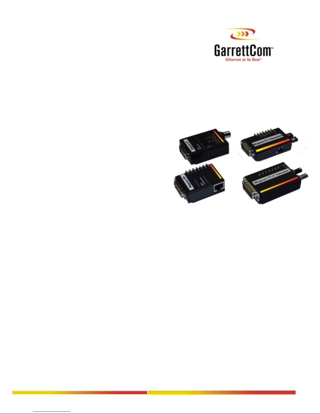
LED/SWITCH SETTING DESCRIPTION & OPERATION
Each Magnum Mini-Transceiver is equipped with switches and LEDs to allow
for configuration and quick visual assessment of its operating condition.
Magnum TP1
LED Color Indication
LINK green Connectivity est ablished / normal operation
COL yellow Collision has occurred
REC green Data is being received from attached segment;
TRAN green Data is currently transmitted by attached station
POL yellow Polarity error on the TP segment.
SQE yellow SQE Test feature enabled
PWR green Unit receiving power
SWITCH SETTING
POL On=Automatic correction for reversed
RED. S QUELCH On=Shie lded Twisted Pair (STP);
LINK On=10BASE-T; Off=Starlan 10 (ATT)
SQE Enables or Disables the SQE Test feature
FACTORY SETTING OF SWITCHES
RED. SQUELCH Off
AUTO POL On
LINK On
SQE On
10BASE-T MODULAR JACK PINOUT
RJ45 PIN SIGNAL
1 Transmit Data + 5 no connec tion
2 Transmit Data - 6 Receive Data 3 Receive Data + 7 no connection
4 no connection 8 no connection
AUI
Connector
flashes to indicate data traffic
Off=Uns hielded Twisted Pair (UTP)
polarity on the segment.
Link
Magnum TP1
Figure 2: Front View - Magnum TP1
(when lit)
RJ45 PIN SIGNAL
Col
Rec
Tran
Pol
Sqe
Pwr
Switches
Mini
Transceiver
TP
Connector
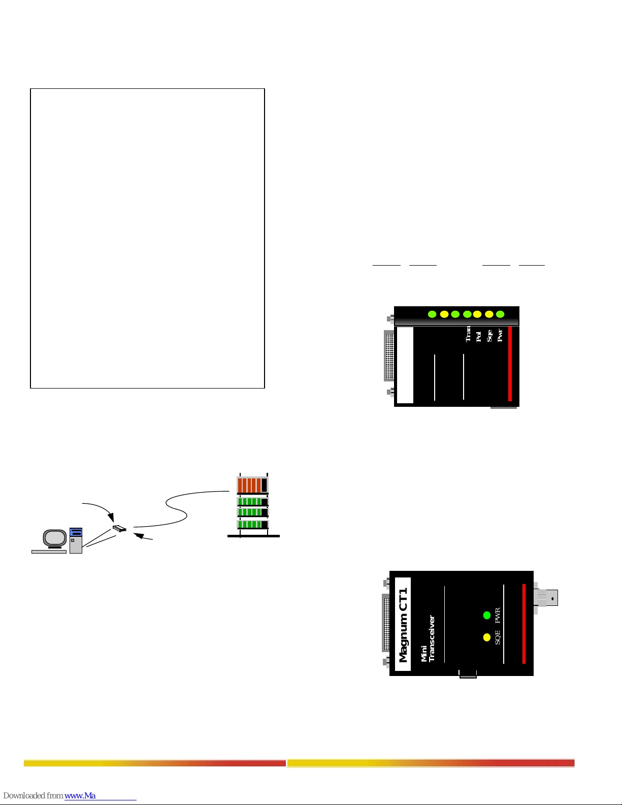
Magnum CT1
LED Color Indication
SQE yellow SQE enabled
PWR green Unit receiving power
(when lit)
AUI
Connector
.
.
.
.
.
Figure 1: Magnum TP1 Provides Connectivity Between
Workstation and 10BASE-T Network
RJ-45
Connector
OPERATION
The function of a Magnum Mini-Transceiver converts the station signal to
appropriate network media; i.e. it converts traffic signaling between station
signaling a nd 10BASE-T signaling.
The TP1 Twisted Pair Mini-Transceiver is designed to connect an existing AUI
device to a 10BASE-T (TP) network. (Note: By using a shielded AUI extension
cable, and selecting RED SQUELCH function switch to ON position, the unit
can be used on shielded twisted pair (STP) networks.)
The CT1 10BASE2 ThinNet Mini-Transceiver is intended to be used with
ThinNet coaxial, 50 Ohm, RG-58 A/U cable. Cable runs should not exceed 180
meters in total length. A 50 Ohm terminator is required at both ends of the
segment. Taps should be at least 0.5 meters apart.
..
www GarrettCom com
SWITCH SETTING
SQE Enables or Disables the SQE Test feature
FACTORY SETTING OF SWITCH
SQE On
AUI
Connector
www G a rre ttC o m co m
..
Figure 3: Front View - Magnum CT1
SQE PWR
Mini
Transceiver
Magnum CT1
OFF
SQE
ON
SQE
Enable/Disable
Switch
BNC
Connector
 Loading...