

Page 1

Magnum DX940
Configurable Industrial
Router
Installation
Guide
GarrettCom, Inc.
47823 Westinghouse Drive,
Fremont, CA 94539, US A
Phone (5 10) 438-9071
Fax (510) 43 8-9072
$5.00 USD
Page 2

Declarations
DOCUMENT N
OTICE
Copyright
Copyright 2010 by GarrettCom Inc. Printed in the US. All rights reserved.
This manual may not be reproduced or disclosed in whole or in part by any means without the written
consent of GarrettCom. DynaStar is a trademark of GarrettCom Inc. All other trademarks mentioned in
this document are the property of their respective owners.
This document has been prepared to assist users of equipment manufactured by GarrettCom and
changes are made periodically to the information in this manual. Such changes are published in
Software Release Notices. If you have recently upgraded your software, carefully note those areas
where new commands or procedures have been added. The material contained in this manual is
supplied without any warranty of any kind. G arrettCom therefore assumes no responsibility and shall
incur no liability arising from the supplying or use of this document or the material contained in it.
Rights
Except as set forth in the Software License Agreement, GarrettCom makes no representation that
software programs and practices described herein will not infringe on existing or future patent rights,
copyrights, trademarks, trade secrets or other proprietary rights of third parties and GarrettCom makes
no warranties of any kind, either express or implied, and expressly disclaims any such warranties,
including but not limited to any implied warranties of merchantability or fitness for a particular purpose
and any warranties of non- infringement. The descriptions contained herein do not imply the granting of
licenses to make, use, sell, license or otherwise transfer GarrettCom products described herein.
GarrettCom disclaims responsibility for errors which may appear in this docume
right, in its sole discretion and without notice, to make substitutions and modifications in the products
and practices described in this document.
nt, and it reserves the
Part Number Information
Part Number: 84-00187Z
Last Update: July 2010
Page 3

DECLARATIONS
W
ARRANTY
GarrettCom warrants equipment manufactured by it to be free from defects in materials and
workmanship for a period of three (3) years from date of shipment. If within the warranty period the
purchaser discovers such item was not as warranted above and promptly notifies GarrettCom in
writing, GarrettCom shall repair or replace the items at the company's option. This warranty shall not
apply to: (a) equipment not manufactured by GarrettCom; (b) equipment which shall have been
repaired or altered by anyone other than GarrettCom; (c) equipment which shall have been subjected
to negligence, accident, or damage by circumstances beyond GarrettCom control, or to improper
operation, maintenance or storage,
sold but not manufactured by GarrettCom, the warranty obligation of GarrettCom shall, in all aspects,
conform and be limited to the warranty actually extended to GarrettCom by its supplier.
The
foregoing warranties do not cover reimbursement for labor, transportation, removal, installation,
or other
THE FOREGOING WARRANTIES ARE EXCLUSIVE AND IN LIEU OF ALL OTHER EXPRESS AND
IMPLIED WARRANTIES EXCEPT WARRANTIES OF TITLE, INCLUDING, BUT NOT LIMITED TO,
IMPLIED WARRANTIES OF MERCHANTABILITY AND FITNESS FOR A PARTICULAR PURPOSE.
expenses that may be incurred in connection with repair or replacement.
or to ot
her than normal use or service. With respect to equipment
LIMITATION OF L
Anything to the contrary herein contained notwithstanding, GarrettCom, ITS CONTRACTORS AND
SUPPLIERS OF ANY TIER, SHALL NOT BE LIABLE IN CONTRACT, IN TORT (INCLUDING
NEGLIGENCE OR STRICT LIABILITY) OR OTHERWISE FOR ANY SPECIAL, INDIRECT,
INCIDENTAL OR CONSEQUENTIAL DAMAGES WHATSOEVER. The remedies of the purchaser set
forth herein are exclusive where so stated and the total cumulative liability of GarrettCom its contractors
and suppliers of any tier, with respect to this contract or anything done in connection therewith, such as
the use of any product covered by or f urnished und er the contract, whether in contract, in tort (including
negligence or strict liability) or otherwise, shal l not exceed the price of the product or part on which such
liability is based.
Un
less otherwise agreed to in writing by an authorized official of GarrettCom, products sold hereunder
are not intende d for use in or in connection with a nuclear facility or activity. If so used, GarrettCom
disclaims all liability for nuclear damage, injury or contamination, and purchaser shall indemnify
GarrettCom against any su ch liabi lity, whether as a result of breach of contract, warranty, tort (including
negligence) or otherwise.
IABILITY
Page 3
Page 4

DECLERATIONS
P
ATENTS
As to equipment proposed and furnished by GarrettCom, GarrettCom shall defend any suit or
proceeding brought against purchaser so far as based on a claim that said equipment constitutes an
infringement of any patent of the United States, if notified promptly in writing and given authority,
information, and assistance at GarrettCom's expense for the defense of the claim. In event of a final
award of costs and damages from such a suit, GarrettCom shall pay such award. In event the use of
said equipment by purchaser is enjoined in such a suit, GarrettCom shall, at its own expense, a nd at its
sole option either (a) procure for purchaser the right to continue using equipment, (b)
equipment to render it non-infringing, (c) replace said equipment with non-infringing equipment, or (d)
refund the purchase price (less depreciation) and transportation and installation costs of said
equipment. GarrettCom will not be responsible for any compromise or settlement made without its
written consent. The foregoing states the entire liability of GarrettCom for patent infringement, and in no
event shall GarrettCom be liable if the infringement charge is based on the use of GarrettCom
equipment for a purpose other than that for which it was sold by GarrettCom As to any equipment
furnished by GarrettCom to purchaser and manufactured in accordance with designs proposed by
purchaser, purchaser shall indemnify GarrettCom against any award made against GarrettCom for
patent, trademark
, or copyright infringement.
modify said
RETURN OF E
No equipment may be r eturned without purchaser first obtaining written Return Material Authorization
(RMA) from GarrettCom. An RMA can be obtained by contacting Sales at 510-438-9071.
Equipment accepted for credit, not involving a GarrettCom error, shall be subject to all the terms of the
original purchase contract and to a service charge. Returned equipment must be of current
manufacture, unused, and in reasonable condition, securely packed to reach GarrettCom without
damage, shipped F.O.B. GarrettCom facilit y with transportation charges paid, and labeled with Return
Material Authorization (RMA) number. Any cost incurred by GarrettCom to put equipment in first class
condition will be charged to purchaser.
COMPLIANCE N
QUIPMENT
OTICES
FCC Part 15
This device complies with part 15 of the FCC Rules. Operation is subject to the following two
conditions: (1) This device may not cause harmful interference, and (2) this device must accept any
interference received, including interference that may cause undesired operation.
Note: This equipment has been tested and found to comply with the limits for a Class A digital device,
pursuant to part 15 of the FCC Rules. These limits are designed to provide reasonable protection
against harmful interference when the equipment is operated in a commercial environment. This
equipment generates, use s and can radiate radio frequency energy and, if not installed and used in
accordance with the instruction manual, may cause harmful interference to radio communications.
Operation of this equipment in a resident ial area is likely to cause harmful interference in which case
the user will be required to correct the interference at his/her own expense.
In order to maintain compliance with FCC regulations shielded cables must be used for electrical I/O
with this equipment. Operation with non-approved equipment or unshielded cables may result in
interference to radio and television reception.
Page 4
Page 5

DECLERATIONS
Changes or modifications could void the user’s authority to operate the equipment. The user is
cautioned not to change or modify this product.
FCC Part 68
This device complies with part 68 of the FCC rules and the requirements adopted by the ACTA. On the
bottom of this equipment is a label that contains, among other information, a product identifier in the
format US:AAAEQ##TXXXX. If requested, this number must be provided to the telephone company.
Note: REN (Ringer Equivalence Number) does not apply to this equipment.
IC CS03 (Industry Canada)
This digital apparatus does not exceed the Class A limits for radio noise emissions from digital
apparatus set out in the interference-causing equipment entitled “Digital Apparatus”, ICES-003 of the
department of Communications (Cet appareil numérique respecte les limites bruits radioélectriques
applicables aux appareils numériques de Class A prescrites dans la norme sur le materiel brouilleur:
“Appareils Numériques”, NMB-003 édictée par le ministre des Communications).
This product meets the applicable Industry Canada technical specifications/Le présent materiel
conforme
aux specifications techniques applicables d’Industrie Canada.
est
EN55022
Warning: This is a Class A product. In a domestic environment this product may cause radio
interference, in which case the user may be required to take adequate measures.
S
AFETY
WARNING: Service to this unit can be made only by factory authorized personnel. Failure to observe
this caution can result in malfunction to the unit as well as electrocution to personnel.
Avertissement: Cet appareil ne peut être examiné ou réparé que par un employé autorisé du
fabricant. Si cette consigne n’est pas respectée, il y a risque de panne et d’électrocution.
Vorsicht: Dieses Gerät darf nur durch das bevollmächtigte Kundendienstpersonal der
instandgehalten
führen und das Personal durch Stromschläge gefährden.
fabrik
werden. Die Nichtbeachtung dieser Vorschrift kann zu Fehlfunktionen des Gerätes
Page 5
Page 6

DECLERATIONS
Industry Canada Warnings Avis d’Industrie Canada
Notice:
Before installing this equipment, users should
ensure that it is permissible to be connected to
the facilities of the local telecommunications
company. The equipment must also be installed
using an acceptable method of connection. The
customer should be aware that compliance with
the above conditions may not prevent
degradation of service in some situations.
Repairs to certified equipment should be
coordinated by a representative designated by the
supplier. Any repairs or alterations made by the
user to this equipment, or equipment
malfunctions, may give the telecommunications
company cause to request the user to disconnect
the equipment.
Users should ensure for their own protect ion th at
the electrical ground connections of the power
utility, telephone lines, and internal metallic water
pipe system, if present, are connected together.
The precaution may be particularly important in
rural areas.
Avis:
Avant d’installer ce matériel, l’utilisateur doit
s’assurer qu’il est permis de le raccorder aux
installations de l’entr eprise locale de
télécommunication. Le matériel doit également
être installé en suivant une méthode acceptée
de raccordement. L’abonné ne doit pas oublier
qu’il est possible que la conformité aux
conditions énoncées ci-dessus n’empêche pas
la dégradation du service dans certaines
situations.
Les réparations de matériel homologué doivent
être coordonnées par un représentant désigné
par le fournisseur. L’entreprise de
télécommunications peut demander à l’utilisateur
de débrancher un appareil à la suite de
réparations ou de modifications effectuées par
l’utilisateur ou à cause de mauvais
fonctionnement.
Pour sa propre protection, l’utilisateur doit
s’assurer que tous les fils de mise à la terre de la
source d’énergie électrique, des lignes
téléphoniques et des canalisations d’eau
métalliques, s’il y en a, sont raccordés ensemble.
Cette précaution est particulièrement importante
dans les régions rurales.
Service
The DX940 device may be AC or DC powered. Remove all power connections at the circuit panel
before removing the unit.
The installation of this product must comply with all applicable codes and practices specified by the
country, city, and operating company in which it is installed.
Personnel Warning
Grounding
All units require grounding. Use a grounding wire with a minimum size of 14 AWG at a maximum
length of five feet.
The DX940 is equipped with an external grounding bolt (#10/32 UNF-2B). The ground lug bolt torque
rating is 32 inch pounds (3.6 Nm).
Page 6
Page 7

CONTACTING G ARRETTCOM
CONTACTING G
ARRETTCOM
Website: www.garrettcom.com
By Mail: GarrettCom Inc.
47823 Westinghouse Drive,
Fremont, CA 94539, USA
Telephone: 510-438-9071
Fax: 510-438-9072
Email:
support@garrettcom.com
Page 7
Page 8
Preface
ABOUT THIS M
This document provides instructions for installing the Magnum DX940 hardware. This docum ent gives
product descriptions, specifications, detailed information on ports and pin-outs, all site preparation
required to install the product, complete installation procedures, power up instructions, and instructions
for removing and maintaining the product. This document is arranged as follows:
Chapter 1, “Overview” - Contains a brief product description, a list of applicable specifications,
description of all controls and indicators and pin-outs for connectors.
Chapter 2, “Installation” - Contains all site preparation that must be accomplished prior to installing the
DX940, installation in a rack, panel, or DIN-Rail system, powering the unit up, and making all external
connections. This chapter also includes maintenance procedures.
C
ONVENTIONS
Graphically distinctive alerts labeled either “Note” or “Caution” (illustrated below) are
interspersed throughout this manual. These alerts call your attention to useful information
related to the text immediately following the alert. Notes provide supplemental information or
provide a point of emphasis. Cautions warn you of the risk of poor system performance or of
system failure.
NOTE: Notes provide you with helpful information about an upcoming step or action.
If you do not use the information contained in a Note there is no risk of harm to the
system, but using the information will improve performance and/or increase your
understanding.
ANUAL
and
CAUTION: A caution warns you that you should take some action to avoid poor
system performance or system failure.
LASER WARNING: This Warning is used to call attention to the fact that Laser
output can cause serious damage to the eye.
ELECTRICAL WARNING: This format is used for Electrical Warnings.
Callouts of this format are used to notify that a potential of electrocution
exists and that a defined action could cause personal injury or death to occur.
a
WEB A
All of the DX940 installation guide is also available in a PDF format on the GarrettCom website,
http://www.garrettcom.com/techsupport/hardware/userguides/dx940ug.pdf. See Datasheet and
Administrator Guide sections in this guide for information on other related documents.
CCESS
Page 9

PREFACE
YOUR C
If you find an error or have a helpful tip on the layout or informational content of this or any other
GarrettCom manual please feel free to contact us via email with any problems or helpful
information. All enquiries will be responded to with a correction or whatever resolution is
required. Please make all comments to support@garrettcom.com or phone a support engineer
510-438-9071.
at
OMMENTS
Page 9
Page 10

Chapter 1
Overview
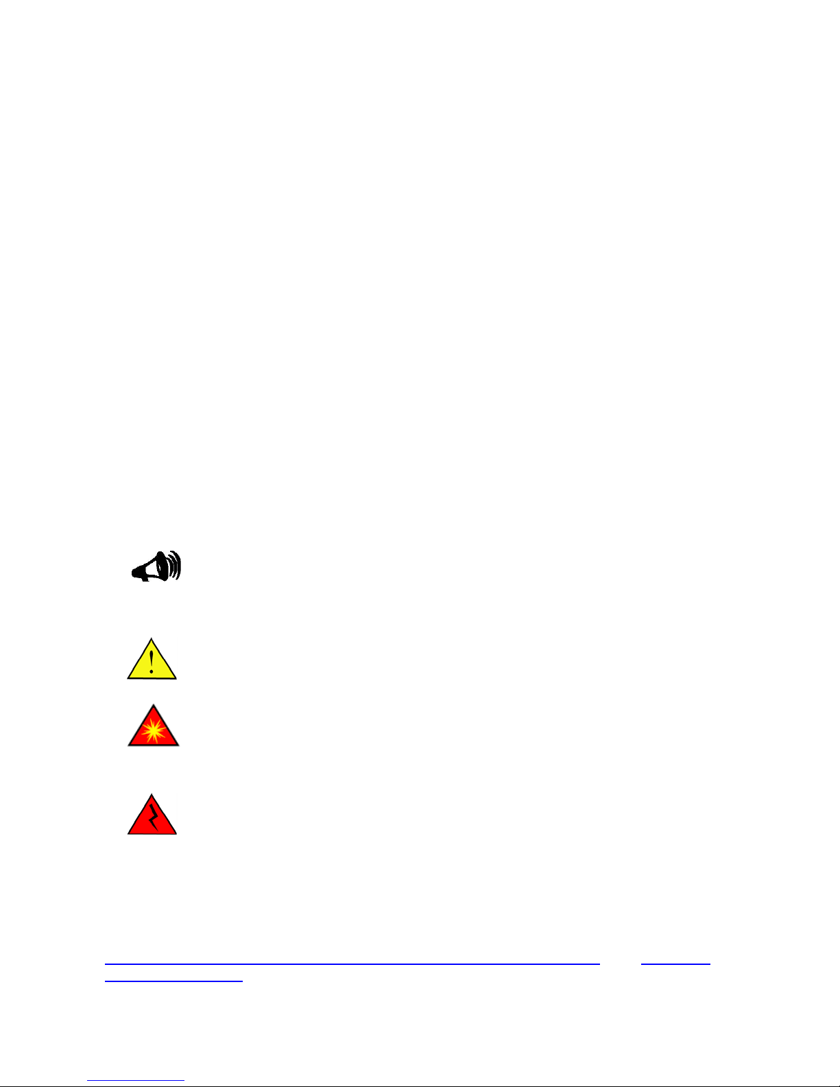
1.1 Overview
The Magnum DX940 can be configured at order time and provides connectivity to Ethernet via four
10/100 Base-T Ethernet p orts or 100Mbps Fiber por ts via SFP's. Additiona lly, two 10/100/ 1000 Base-T
ports can be added for Gigabit connectivity or 1000Mbps fiber ports (via SFP) can be added for
1000Mbps fiber connectivity. Other connectivity options includes optional four programmable serial
ports, and one DDS or T1/E1 WAN port. Optionally a 3G cellular wireless interface can be added as
well.
1.2 Configuration
The following sections describe the features and requirements of the DX940.
1.2.1 Connectivity
The DX940 is equipped with:
• (Optional) 1 DDS or T1/E1 WAN port. Instead of the DDS or T1/E1 port or a 3G cellular
wireless interface.
• 4 Ethernet ports 10/100 Base-T, RJ45 OR 4 SFP 100Mbps ports. These are labeled E3
through E6. All ports are disabled by default, except E6.
• (Optional) 2 Ethernet 10/100/100 Base-T ports OR 2 SFP 1000Mbps ports. These ports
are labeled E1 and E2. These ports are disabled by default.
• (Optional) 4 Serial programmable RS232/485 ports.
These ports are all located on the front face of the device, as shown below in Figure 1-1.
Page 11
CHAPTER 1 - OVERVIEW
Figure 1-1. Different ports and capabilities of DX940
Figure 1-1(a) - Front View of DX940 (without the WAN port). This view shows the optional
Gigabit Ethernet ports E1, E2; 10/100 Eth ernet port E 3 to E6 and optio nal seria l ports S1 to
S4.
1.2.2 Power and Ground
The DX940 can be ordered with a high (90 -250 VAC or VDC) or Low (24-48 VDC) voltage power
supply. The connection point for the power supply is located at the rear of the chassis. The rear face
also contains the primary ground stud and labels including serial num ber, model
power specifications.
For detailed power specifications see
Power Requirements.
number, and
port and
Page 11
Page 12

CHAPTER 1 - OVERVIEW
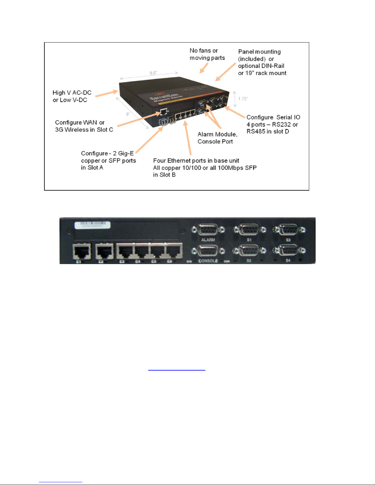
Figure 1-2. Rear
View
NOTE: The hot surfaces warning label (
because the device is rated to operate at ambient temperatures as high as 85
o
F). Clearly, if
(185
temperatures at the
the device
upper end
were to be installed in an environment in which
of its operating rang e were attained, the metal
) is affixed to this device
o
C
surfaces of the device would become too hot to touch.
1.2.3 Indicators
The operational status of the ports of the DX940 is indicated by LEDs located near the physical ports on
the front of the DX940, as illustrated in Figure 1-1, and a bank of LEDs on the top of the chassis, as
illustrated in Figure 1-3.
Figure 1-3. Top View of DX940. See below for LED details.
In Figure 1-3, the LEDs ar e sho wn for Console Port; Alarm Port; and E3 throug h E6. Ethernet Ports E3
through E6 are 10/100 copper ports or 100Mbps Fiber ports (using SFPs).
Depending on the options order ed, additional LED's may be displayed in the boxes labeled "A" and " B"
(shown by the red dotted line) in Fig ure 1-3 abo ve. "A" and " B" (as s hown in Figu re 1-3 above) can have
possible combinations of LEDs as shown in Fi gure 1-3(a) below.
Page 12
Page 13

CHAPTER 1 - OVERVIEW
Figure 1-3(a). Possible LEDs in posit ions "A " and "B" sho wn in Figure 1-3 above.
The LEDs shown in Figure 1-3(a) are as follows:
• E1, E2 - Gigabit Ethernet ports.
• C1 - Cellular Interface.
• W1 - WAN Port.
• S1 through S4 - Four Serial ports labeled S1, S2, S3 and S4.
1.2.4 Mounting Options
There are three mounting options for the DX940:
• 19” rack mount (see
• Panel mount (see
• DIN-Rail mount (see
Each of these options requires specific accessory hardware. Each type of accessory hardware
mates up with a specific set of screw holes on the sides of the chassis, illustrated in Figure 1-4.
Mounting in a 19" Rail Sy ste m)
Mounting on a Pa nel )
Mounting in a DIN-Rail System)
View
Figure 1-4. Side
Page 13
Page 14

CHAPTER 1 - OVERVIEW
1.3 Specifications
The following sections provide detailed information about the physical, electronic,
specifications of the DX940.
1.3.1 Physical
The physical dimensions and weight of the DX940 are defined in Table 1-1.
Height:
Width:
Depth:
Weight:
Table 1-1. Physical
1.75 inches (4.45 cm)
9.5 inches (24.13 cm)
9.0 inches (22.86 cm)
5.0 lbs (2.3 kg)
Specifications
1.3.2 Environmental
The environmental specifications of the DX940 are defined in Table 1-2.
Table 1-2. Environmental Specifications
and industrial
o
-40
C to 85oC (-40oF to 185oF)
Operating Temperature:
Storage Temperature:
Operating Humidity:
IAW 60950-1, installations in
restricted access locations.
No fans
o
-40
C to 85oC (-40oF to 185oF)
95% non-condensing
Page 14
Page 15

CHAPTER 1 - OVERVIEW
1.3.3 Compliance
The industry compliance profile of the DX940 is defined in Table 1-3.
Industrial:
Emissions:
Immunity:
Safety
Table 1-3. Compliance With Standards
IEEE 1613, IEC 61850-3
EN55022A, FCC Part 15A
EN55024 EN61000-4-6 (CRF)
EN61000-6-2 EN61000-4-10 (MagField)
EN61000-6-5 EN61000-4-11 (VDI)
EN61000-4-2 (ESD) EN61000-4-12 (Oscillatory)
EN61000-4-3 (RF) EN61000-4-16 (CCM)
EN61000-4-4 (EFT) EN61000-4-17 (Ripple)
EN61000-4-5 (SURGE) EN61000-4-29 (VDI)
UL60950, EN60950
1.3.4 Power Requirements
The power requirements of the DX940 are defined in Table 1-4.
Table 1-4. Power
High Voltage AC/DC Low Voltage DC
Requirements
Voltage Input Range:
Max. Power (Watts):
Typical Power (Watts):
Max. Amperage (Amps):
90-250 VAC/VDC 24-48 VDC
27 27
10 10
0.5 2.0
Page 15
Page 16

CHAPTER 1 - OVERVIEW
T1/E1 – CSU/DSU WAN connection.
ed
1.3.5 Ports and External Connectors
The ports and external connectors of the DX940 are defined in Table 1-5.
Port Name Connector
Table 1-5. Ports and External Connectors
• DDS – 56/64 Kbps DDS CSU/DSU WAN
WAN, W1 RJ48
connection.
•
10/100/1000 Mbps Ethernet port for connection to
Ethernet, E1 – E2 RJ45 or SFP
Ethernet, E3 – E6 RJ45 or SFP
Serial, S1 through S4 DB9, female
Power Connection
Facility Ground Point Lug bolt Facility ground connection point.
Console
Terminal block Non-polarized power input.
DB9, female
copper Ethernet capable devices. With SFP, the spe
is set to 1000Mbps. SFP provides the LC connector.
10/100 Mbps Ethernet port for connection to copper
Ethernet capable devices. With SFP, the speed is set
to 100Mbps. SFP provides the LC connector.
Connection to serial async devices. Configurable to
300, 600,1200, 2400, 4800, 9600, and 19.2, 28.8,
33.6, 38.4, 57.6, 115.2, 230.4 Kbps.
Configured to operate at 38400 Baud, 8 bits, No
parity, one stop bit and is configured as a DTE.
Description
Alarm
DB9, female
Carries alarm signals to provide notification of events
specified by software configuration.
NOTE: All copper I/O c onnections must be made with s hielded cables and
connectors.
1.3.6 Indicators
The status indicators of the DX940 are described in Table 1-6. There are two sets of LEDs so
can conveniently monitor activity regardless of the orientation of the device. See
details.
Figure 1-3 for more
that
you
Page 16
Page 17

CHAPTER 1 - OVERVIEW
Table 1-6.
Indicators
LED Name Condition
Green Indicates an active circuit.
W1
(WAN DDS or
T1/E1 Port)
S1 – S4
(Serial
Ports)
E1 – E6
(Ethernet
Ports)
Console
Off
Flashing Data is passing through the port.
Green Port is connected to an active serial device.
Off Port is down.
Flashing Data is passing through the port.
Green Port is connected to an active Ethernet device.
Off Port is down.
Flashing Data is passing through the port.
Green Connected to an active local ter minal.
Off Not connected.
Flashing Data is passing through the port.
Off No power is applied to unit.
Indicates circuit is down or not configured
properly.
Indication
Alarm
Red Reset state: System is not loaded
Orange System is being booted.
Green Normal operation.
Green Indicates an active circuit.
C1
(Cellular Wireless
Interface)
Off
Flashing Data is passing through the port.
Indicates circuit is down or not configured
properly.
Page 17
Page 18

CHAPTER 1 - OVERVIEW
Pin
4
5
6
7
Pin
Rx Data - Tip
not used
1.4 Pin-outs
The following subsections describe the pin-outs of the connectors used with the DX940.
1.4.1 RJ48 DDS Connection
Table 1-7 defines the pin-out of the RJ48 connector used on port W1 with the DDS
Table 1-7. RJ48 DDS Pin-out
1
2
3
8
Signal
Tx Data - Ring
Tx Data - Tip
not used
not used
not used
not used
Rx Data - Tip
Rx Data - Ring
connection.
1.4.2 RJ48 T1/E1 Connection
Table 1-8 defines the pin-out of the RJ48 connector used on port W1 with the T1/E1 connection.
Table 1-8. RJ48 T1/E1 Pinout
1
2
3
4
5
6
7
8
Signal
Rx Data - Ring
Tx Data - Ring
Tx Data - Tip
not used
not used
not used
Page 18
Page 19

CHAPTER 1 - OVERVIEW
Pin
Pin
1.4.3 RJ45 for 10/100 Ethernet Ports
Table 1-9 defines the pin-out of the RJ45 connector used with the DX940.
RJ45 connectors
are used on ports E3 though E6 for 10/100 Base-T connections to copper Ethernet-capable
devices.
Table 1-9. RJ45 Pin-out
Signal
Tx +
1
Tx -
2
Rx +
3
not used
4
not used
5
Rx -
6
not used
7
not used
8
1.4.4 RJ45 for 10/100/1000 Ethernet Ports
Table 1-10 defines the pin-out of the RJ45 connector used with the DX940.
are used on ports E1 and E2 for 10/100 Base-T connections to copper Ethernet-capable
devices.
Table 1-10. RJ45 Pin-out
Signal
TD0+
1
TD0-
2
TD1+
3
TD2+
4
TD2-
5
TD1-
6
TD3+
7
TD3-
8
RJ45 connectors
Page 19
Page 20

CHAPTER 1 - OVERVIEW
In
In
In
NC1 - normally closed 1
COM2 - common 2
Reserved for future use
GND - signal ground
COM1- common 1
NC2 - normally closed 2
NO2 - normally opened 2
Reserved for future use
1.4.5 DB9 (Female) – RS232 Serial Ports and Console Port
Table 1-11 defines the pin-out of the DB9 female connector for the console port and for ser ial por ts S1 S4 when they are configured for the RS232 interface. DB9 connectors are used on RS232 serial ports
S1 - S4 and the console port, for asynchronous connections.
Pin Name Dir. Description
1
2
3
4
5
6
7
8 CTS In Clear to Send.
9 RI In Ring Indicator from DCE.
DCD
RXD
TXD
DTR
GND
DSR
RTS
Table 1-11. DB9 Pin-out
Data Carrier Detect from DCE.
Receive Data from DCE.
Out
Out
Pwr
Out
Transmit Data to DCE.
Data Terminal Ready to DCE.
Signal Ground.
Data Set Ready from DCE.
Request To Send.
1.4.6 DB9 (Female) – Alarm Port
Table 1-12 defines the pin-out of the DB9 female connector used with the alarm port on the
Table 1-12. DB9 Pin-out
Pin Signal
1
2
3
4
5
6
7
8
9
NO1 - normally opened 1
DX940.
Page 20
Page 21

CHAPTER 1 - OVERVIEW
RX+
In 3 TX-
Out TX+
Out 5 GND
Power
Not Used
7 Not Used
8 Not Used
9 Not Used
1.4.7 DB9 (Female) – RS485 Serial Ports
Table 1-13 defines the pin-out of the DB9 female connector used with serial ports on the
DX940 when they are configured for the RS485 interface.
Table 1-13. DB9 RS485 Pin-out
Pin Signal
1
RX_ In
2
6
Page 21
Page 22

Chapter 2
Installation
This chapter provides specific procedures for installing the Magnum DX940, preparing for installation, and
uninstalling the device.
2.1 Preparing for Installation
The DX940 is designed to be installed in standard 19" racks, on a DIN-Rail system, or on a panel.
2.1.1 Tools
Regardless of the mounting system you are using you will need the following tools:
• Two screw drivers – one Phillips head and one slot.
• A torque wrench (rated for ten and 32 inch pounds, or 1.1 Nm and 3.6 Nm)
• A wrench to connect a ground wire from the device chassis to a ground
The instructions in this manual cover only the physical installation. System configuration is handled through
a web-based interface and is described in the
MNS-DX
Administrator’s Guide.
2.1.2 Site Suitability
Be sure that your installation site meets the following criteria:
Conforms with the temperature and humidity ranges detailed in Table 1-2.
Can meet the power requirements detailed in Table 1-4.
Will remain stable after the addition of the 5 lb. DX940.
Permits at least two inches of space between the DX940 and any other heat
producing device.
2.1.3 Wiring and Grounding Guidelines
The DX940 requires several different types of connectors, cables, and wires. Requirements and
recommendations are listed below:
Grounding
Facility Power
The primary ground stud located on the rear of the chassis
must be used to connect to an approved ground with a wire
meeting the following criteria:
• 14 AWG (minimum)
• a maximum of five feet in length
• terminated on the ground lug side with a #10 ring lug
The facility power cabling attached to the DX940 chassis must meet the
following
criteria:
Page 23

CHAPTER 2 - INSTALLATION
• cabling constructed using 14 AWG stranded wire
• cable firmly attached to the terminal holes of the
• non-polarized power unit, as illustrated in Figure 2-11.
• cable routed and strain relieved to the chassis according to
Copper
good wiring practices
Copper I/O cables and connectors must be shielded.
2.1.4 External
You can speed up the installation of the DX940 by having the following equipment and information on
hand before beginning:
• A supply of cables and connectors of the required types.
• IP addresses for new devices and any existing devices you will be
connecting to.
• Your notes on naming conventions and end point information.
Connections
2.2 Unpacking
Unpack and inspect the DX940.
The DX940 is shipped with the following items in the box:
• DX940 unit
• Appropriate mounting brackets (19’ rail, or DIN-Rail, or panel as ordered), with screws
• Console Cable - DB9 terminations, 10' long
•
Be sure that all the equipment you have ordered is included in the shipment.
Remove the unit from the styrofoam end caps and inspect the DX940 chassis for dents or other shipping
related damage. Report any damage immediately to GarrettCom customer support and DO NOT INSTALL
the unit.
Ethernet cable - RJ45 terminations, 10' long
2.3 Installation of the DX940 Unit
To install the DX940 you must first
• Mount it
• Make the ground and power connections.
• Connect the network cables
2.3.1 Mounting
Your DX940 shipment includes the mounting hardware you have ordered as appropriate to your
site. This hardware is one of:
• A pair of L-shaped brackets (2.12” x 4.5”) for conventional mounting in a 19” rail
system (that is, with I/O connections on the “aisle side” of the
• A pair of L-shaped brackets (8.75” x 4.5”) for reverse mounting in a 19” rail system
rack).
Page 23
Page 24

CHAPTER 2 - INSTALLATION
(that is, with I/O connections on the “wire side” of the rack).
• A pair of 1.5” brackets for mounting on a panel.
• A DIN-Rail mounting bracket.
2.3.1.1 Mounting in a 19” Rail System
The DX device can be mounted in a 19” rail system with the I/O connectors on the aisle side and the power
and ground connectors on the wire side (conventional mounting) or in the reverse configuration.
Figure 2-1 - Top View: 19” Rail Conventional and Reverse Mounting
Conventional Mounting
The brackets for mounting in a 19-inch rail system attach with two screws to the screw holes
located toward the front of the DX (see
Figure 1-4
within the mounting system to four positions:
• By your selection of which pair of screw holes on the short side of
t (that is, the side that attaches to the DX940) to use.
bracke
• By setting the long side of the bracket (that is, the side that attaches to the
rail system) toward the front of the DX940 or toward the rear.
). You can adjust the depth of the device
the
Page 24
Page 25

CHAPTER 2 - INSTALLATION
Figure 2-2. 19” Rail Mounting brackets
Figure 2-3. 19” Rail Conventional Mounting - Dimensional Drawing
Page 25
Page 26

CHAPTER 2 - INSTALLATION
Reverse Mounting
The brackets provided for reverse mounting have an opening in their forward projecting parts
to accommodate the power cable.
Figure 2-4. 19” Rail Reverse Mounting brackets
Figure 2-5. 19” Rail Reverse Mounting - Dimensional Drawing
Page 26
Page 27

CHAPTER 2 - INSTALLATION
2.3.1.2 Mounting on a Panel
Each bracket for mounting on a panel attaches with two screws to the screw holes located toward the rear
of the DX940 (see
your selection of which pair of screw holes to use in attaching the bracket to the DX940.
Figure 1-4). You can adjust the distance of the DX940 from the panel to two positions by
Figure 2-6. Panel Mounting brackets
Page 27
Page 28

CHAPTER 2 - INSTALLATION
Figure 2-7. Panel Mounting - Dimensional Drawing
2.3.1.3 Mounting in a DIN-Rail System
To mount the DX-940 on the DIN-Rail follow the following steps:
1) Purchase the SCC -DX-00-DM part which provides the DIN-Rail for DX940.
2) Unpack the ACC-DX-00-DM kit.
3) Discard the Panel mounts as shown below.
Discard the two Panel Mount brackets and the four 10-32x3/8” screws.
Page 28
Page 29

CHAPTER 2 - INSTALLATION
4) Remove the Panel Mount Brac kets pre-installed on t he system by removing the two 6-32x1/4"
screws for each bracket as shown below.
5) Attach the DIN-Rail Latches to the Panel Moun t Brac kets with th e latc h p lu ngers or ient ed to t h e
rear of the DX using two 10-32x3/8" screws as shown below.
6) Reattach the Panel Mount Brackets with DIN-Rail Latches to the DX using the 6-32x1/4"
screws removed in step 3
Page 29
Page 30

CHAPTER 2 - INSTALLATION
2.3.2 Connecting Facility Power
The DX940 comes in either high or low voltage models. The unit does not have a power on/off switch and
is active when the power is connected.
ELECTRICAL WARNING: Always ensure that the ground connection is
made prior
provides a protective circuit connection to ground in cases of transients
and power surges. Connect the facility power to a DC or AC unit as described
in the following sections.
2.3.2.1 Making the Ground and Power Connections
The DX940 provides a hardened DC or AC power supply for industrial applications and/or hostile
environments. The ground lug and power supply connector are located on the rear of the unit as shown
below.
to connecting facility power to the DX940. The ground
Figure 2-10. Ground and Power Connections
ELECTRICAL WARNING: Verify that a proper ground connection is made from
the ground lug to facility ground prior to connecting power to the DX940.
Failure to have a proper ground path could cause serious injury or death to
personnel in cases of power surges.
Making the Ground Connection
The ground wire should be 14 AWG terminated with a #10 ring lug.
Make the facility ground connection as follows:
1. Loosen the ground bolt on the chassis, insert the #10 ring lug, and tighten the ground
bolt.
2. Connect the other end of the ground wire to the facility ground.
Making the Power Connection
The power wires should be 14 AWG. Smaller wires may be used, down to 18 AWG, but verify
that they meet your local electrical requirements.
Connect the power to the unit as follows.
Page 30
Page 31

CHAPTER 2 - INSTALLATION
ELECTRICAL WARNING: Ensure that power is disconnected from wiring
prior to handling! Check the voltage rating next to the power connector
- verify that it matches the power source.
1. Remove the plug portion of the power connector by loosening the two captive
mounting screws.
2. Strip back 1/4" off the insulation of the wires that will connect the unit to the
power source.
3. Loosen saddle screws and insert each conductor firmly into a terminal hole of
the plug (note: this connection is not polarity sensitive.)
4. Visually inspect that no strands of wire are straying out of the hole, potentially
shorting to ground or the other conductor. Tighten the saddle screws until the
wires
are secure.
5. Re-insert the plug into the power connector and secure the two captive
mounting screws.
Figure 2-11. Non-Polarized Power Input
2.3.3 Connecting to the Console Port and the Alarm Port
2.3.3.1 Console Port
The Console Port enables configuration of the device and is connected by a serial cable to a PC.
For hardware installation see
information see
MNS-DX
2.3.3.2 Alarm Port
The alarm port carries alarm signals to provide notification of events specified by software configuration.
The events that can be set to trigger alarms are described in the
Wire the pins of the alarm port appropriately depending on whether your downstream alarm s ystem expects
normally open or normally closed operation. See
the ratings of the alarm port contacts.
"Connecting Network Cables", below. For startup and configuration
Administrator’s Guide.
MNS-DX
Table 1-11 for alarm port pin-out. Table 2-1 below defines
Administrator’s Guide.
Page 31
Page 32

CHAPTER 2 - INSTALLATION
Table 2-1. Alarm Port Contacts Ratings
Nominal Switching Capacity (resistive load)
0.5A at 30VDC, 0.25A at 125VAC
Maximum Switching Power (resistive load)
Maximum Switching Voltage
Maximum Switching Current
15W, 31VA
110 VDC, 125 VAC
0.5A
2.3.4
There are two types of connections that can be made to the DX940. They are serial and Ethernet copper.
The following sections describe each type of connection separately.
Connecting Network
Cables
2.3.4.1 Connecting Serial Cables
This procedure assumes that one end of the serial device cable is already attached to the end unit. Be
aware of the serial port numbering scheme when installing the cables. The ports are configured in software
later on and if a device is accidentally connected to the wrong port it will be difficult to detect.
Connect cables to the Serial ports as described below:
1. Align the DB9 connector with appropriate serial port and push gently until the
connector is completely mated to the port.
2. Tighten the two extended capture screws hand tight.
3. Make sure that the connector is not supporting the whole weight of the cable. Providing strain
relief on these cables will ensure a stable
4. Return to step one above and connect the remainder of the serial cables.
connection.
2.3.4.2 Connecting Ethernet Copper Ca bles
The Ethernet ports are standard RJ45 ports or SFP ports. Connect the shielded Ethernet cables to the
Ethernet ports. For SFP ports make sure the proper SFP is purchased from GarrettCom as well.
Installing the RJ45 ports
1. Install the RJ45 connector into the port with the clip facing down.
2. Push the RJ45 connector into the slot until you hear a click.
3. Give the cable a gentle tug to ensure that the connector clip is firmly seated.
4. Verify that the connection has been made by checking the LED associated with this port
on the top of the DX940 chassis. It should be illuminated. If the link LED is not
illuminated verify that the equipment on the other end of the cable is powered up and
properly connected.
5.
Return to step one above and connect the remainder of the cables.
Installing the SFP ports
1. Install the SFP in the SFP slot in DX940
2. Install the fiber connector in the SFP. Make sure the fiber connector matches the SFP fiber
port type.
3. Gently push the fiber port in till a click is heard. This ensures the fiber connector and the
SFP have mated properly
4. Return to step 1 and install the other fiber ports.
Page 32
Page 33

CHAPTER 2 - INSTALLATION
2.3.4.3 Connecting the WAN Cable
The single WAN connection on the DX940 can be a DDS or a T1/E1 port. An RJ48 is used for both the
DDS and the T1/E1 ports. This is a modular connector that connects the DX940 to the external
telecommunications network. The following procedure assumes that the line and telecom equipment are
ready to accept data traffic from the DX940 and the interfacing cable is already attached to this gear.
Connect the RJ48-terminated cable to the WAN port as follows
1. Install the RJ48 connector into the port with the clip facing down.
2. Push the RJ48 connector into the slot until you hear a click.
3. Give the cable a gentle tug to ensure that the connector clip is firmly seated.
4. Verify that the connection has been made by checking the LED associated with this port
on the top of the DX940 chassis. It should be illuminated. If the link LED is not
illuminated verify that the equipment on the other end of the cable is powered up and
properly connected.
:
2.4 Maintenance
The DX940 is designed to be replaced as a unit. There are no servicing requirements and there
repairable components in this device. Maintenance is limited to replacing the unit.
The following sections detail disconnecting all connections to the chassis, removing the chassis, cleaning
optical devices and packing the DX940 for return to the manufacturer. If it is still possible to connect a
terminal to the malfunctioning DX940 and retrieve any configuration data from the device, do so prior to
removing power.
are
no user-
2.4.1 Removing the DX940
Removing the DX940 entails disconnecting the network cabling, disconnecting the power and ground
lines, and removing the chassis from the rack or other installation location. The unit can then be
packed for shipment to the manufacturer.
2.4.1.1 Disconnecting Network Cable s
The sequence for removal of the serial and Ethernet cables is not important, but it is im por tant to note
that there are active devices connected to each end of the cable.
1. Remove all of the Async DB9 connectors from the serial ports by unscrewing the two
captive screws on each cable and pulling the connector off the port. (Label the
connector with the port number if the cable is to be reconnected at some later time.)
2. Remove the Ethernet RJ45 connectors from the Ethernet ports by pressing on the clip
on the underside of the modular connector and pulling the connector straight out.
(Label the connector with the port number if the cable is to be reconnected at some
later time.) Repeat for the RJ48 WAN connector.
2.4.1.2 Disconnecting Pow er and Ground Line s
ELECTRICAL WARNING: Before disconnecting either AC or DC power
Page 33
Page 34

CHAPTER 2 - INSTALLATION
connections at the DX940 ensure that the facility power has first been turned
off. Failure to shut power off prior to removing the power connections
could expose you to dangerous voltages causing injury or death.
Follow the procedure below to disconnect the power and ground lines.
1. Verify that power to the DX940 is turned off.
2. Use a screw driver to loosen the two screws that tighten the wire clamps in the nonpolarized power connector. Remove the wires from the connector.
ELECTRICAL WARNING: If the wires are not to be used immediately properly
insulate them to ensure that an accidental turning on of the power will not
cause a short or electrical hazard.
3. Remove the ground wire from the chassis by loosening the Ground Lug.
2.4.1.3 Packing the DX940 for Shipment
If you have saved the shipping box that your DX940 was received in then add the end Styrofoam pieces
around the chassis and place the unit in the box. Please contact customer support to receive a valid RMA
number so that this item is either repaired and returned or credited to your account. Products without a
proper RMA number will not be accepted for repair by GarrettCom.
If you have not saved the original shipping container then place the unit in a box so that normal shipp ing
activities will not cause any damage to the unit. GarrettCom has no responsibility for the product during
return shipping. For more warranty information, see
returning equipment, see
Return Of Equipment.
Warranty and for details for the requirements for
2.5 Datasheet
The datasheet for the DX940 is available on the GarrettCom website and is available at
http://www.garrettcom.com/techsupport/hardware/datasheets/dx940ds.pdf
2.6 Administrator Guide
The Administrator Guide for the DX940 is available on the GarrettCom website and is available at
http://www.garrettcom.com/mns_dx.htm - click on MNS-DX Soft ware Manual f or the latest Administrator
Guide.
Page 34
Page 35

Corporate H ea dq u ar t ers
GarrettCom Europe
GarrettCom, Inc.
47823 Westinghouse Drive
Fremont, CA 94539-7437
Phone (510) 438-9071• Fax (510) 438-9072
Email – Tech support – support@garrettcom.com
Email – Sales – sales@garrettcom.com
WWW – http://www.garrettcom.com/
Waterside House
Haslar Marine Technology Park
Haslar Rd, Gosport,
Hants PO12 2AU, UK
Tel: +44 (0) 2392-603-950 • Fax: +44 (0) 2392-603-959
WWW – http://www.garrettcom.co.uk/
 Loading...