

Page 1
Corporate Headquarters
GarrettCom, Inc.
47823 Westinghouse Drive
Fremont, CA 94539
Phone: 510.438.9071
Fax: 510.438.9072
Web: http://www.GarrettCom.com
Email: support@garrettcom.com
:
Magnum Mini-Transceivers
TP1 / CT1
..
www GarrettCom com
www G a rre ttC o m co m
..
Installation & User Guide
Page 2
Magnum Mini-Transceivers
Installation & User Guide
TP1 / CT1
TECHNICAL SPECIFICATIONS
PERFORMANCE
Data Rate: 10 Mbits/second
NETWORK STANDARDS
Ethernet V1.0 and 2.0, IEEE 802.3:
10BASE-T, 10BASE2
MECHANICAL
Enclosure: High strength fabricated metal
Dimensions: TP1: 2.35 in x 1.75 in x 0.75 in
(5.95 cm x 4.45 cm x 1.90 cm)
CT1: 3.40 in x 1.75 in x 0.85 in
(8.65 cm x 4.45 cm x 2.15 cm)
Weight: TP1: 3.4 oz. (97.2g)
CT1: 4.2 oz. (120 g)
MEDIA INTERFACES
TP (10BASE-T): RJ-45 mod. 8-pin female connector
BNC (10BASE2): Standard BNC connector, RG-58 ThinNet
AUI: D-Sub 15-pin Male (w/slide lock)
OPERATING ENVIRONMENT
Ambient t emperature: 32°- 122 F° (0° - 50° C)
Ambient relative humidity: 10% to 95%
(non-condensing)
SAFETY APPROVALS
UL Listed (UL 1950) EMI: Meets FCC
Class A standard
WARRANTY
Three Years Made in USA
Magnum Mini-Transceivers are equipped with an AUI port and either a
10BASE-T (RJ-45) connector or a BNC (10BASE2) connector. The AUI port
can be used to connect directly to the workstation or device in most cases. If
this is not possible, an AUI drop cable (which does not exceed 3 feet in length)
can be used.
LED/SWITCH SETTING DESCRIPTION & OPERATION
Each Magnum Mini-Transceiver is equipped with switches and LEDs to allow
for configuration and quick visual assessment of its operating condition.
Magnum TP1
LED Color Indication
LINK green Connectivity est ablished / normal operation
COL yellow Collision has occurred
REC green Data is being received from attached segment;
TRAN green Data is currently transmitted by attached station
POL yellow Polarity error on the TP segment.
SQE yellow SQE Test feature enabled
PWR green Unit receiving power
SWITCH SETTING
POL On=Automatic correction for reversed
RED. S QUELCH On=Shie lded Twisted Pair (STP);
LINK On=10BASE-T; Off=Starlan 10 (ATT)
SQE Enables or Disables the SQE Test feature
FACTORY SETTING OF SWITCHES
RED. SQUELCH Off
AUTO POL On
LINK On
SQE On
10BASE-T MODULAR JACK PINOUT
RJ45 PIN SIGNAL
1 Transmit Data + 5 no connec tion
2 Transmit Data - 6 Receive Data 3 Receive Data + 7 no connection
4 no connection 8 no connection
AUI
Connector
flashes to indicate data traffic
Off=Uns hielded Twisted Pair (UTP)
polarity on the segment.
Link
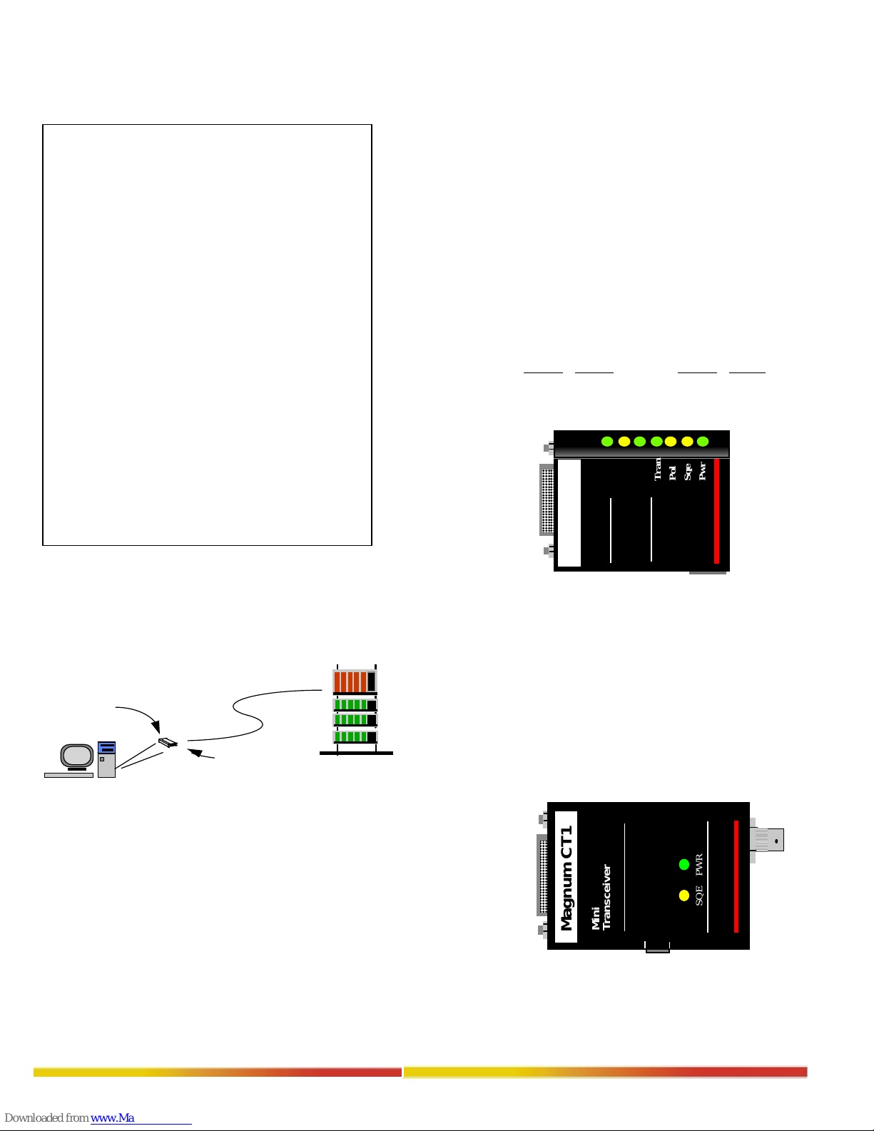
Magnum TP1
Figure 2: Front View - Magnum TP1
(when lit)
RJ45 PIN SIGNAL
Col
Rec
Tran
Pol
Sqe
Pwr
Switches
Mini
Transceiver
TP
Connector
Magnum CT1
LED Color Indication
SQE yellow SQE enabled
PWR green Unit receiving power
(when lit)
AUI
Connector
.
.
.
.
.
Figure 1: Magnum TP1 Provides Connectivity Between
Workstation and 10BASE-T Network
RJ-45
Connector
OPERATION
The function of a Magnum Mini-Transceiver converts the station signal to
appropriate network media; i.e. it converts traffic signaling between station
signaling a nd 10BASE-T signaling.
The TP1 Twisted Pair Mini-Transceiver is designed to connect an existing AUI
device to a 10BASE-T (TP) network. (Note: By using a shielded AUI extension
cable, and selecting RED SQUELCH function switch to ON position, the unit
can be used on shielded twisted pair (STP) networks.)
The CT1 10BASE2 ThinNet Mini-Transceiver is intended to be used with
ThinNet coaxial, 50 Ohm, RG-58 A/U cable. Cable runs should not exceed 180
meters in total length. A 50 Ohm terminator is required at both ends of the
segment. Taps should be at least 0.5 meters apart.
..
www GarrettCom com
SWITCH SETTING
SQE Enables or Disables the SQE Test feature
FACTORY SETTING OF SWITCH
SQE On
AUI
Connector
www G a rre ttC o m co m
..
Figure 3: Front View - Magnum CT1
SQE PWR
Mini
Transceiver
Magnum CT1
OFF
SQE
ON
SQE
Enable/Disable
Switch
BNC
Connector
Page 3

POWER REQUIREMENTS
The Magnum Mini-Transceiver derives power directly from the AUI port on the
device to which it is connected. No external power supply is required.
WORKSTATION INSTALLATION
Magnum Mini-Transceivers attach directly to the AUI connector of the
workstation. Note the following table of pin assignments for the AUI
connector:
Table 1: Pin Assignments for Ethernet Electrical Connectors
Pin Function Pin Function
1 Control in Circuit Shield 9 Control in Circuit B
2 Control in Circuit A 10 Data out Circuit B
3 Data out Circuit A 11 Data out Circuit shield
4 Data in Circuit Shield 12 Data in Circuit B
5 Data in Circuit A 13 Voltage Plus (+)
6 Voltage Common 14 Voltage Shield
7 Control out Circuit A 15 Control out Circuit B
8 Control out Circuit ShieldSHELL Protective Ground
(conductive shell)
NOTES: 1) Voltage Plus (pin #13) and Voltage Common (pin #6) use a single
twiste d pair in the AUI cable
2) Pins 4, 8, 11, and 14 may be connected to pin #1
10BASE-T Wiring Connection - Twisted Pair Segment
The following procedure describes how to connect a 10BASE-T twisted pair
segment to the Magnum TP1. The procedure is the same for both unshielded
and shielded twisted pair segments.
1) Using standard 10BASE-T media, insert either end of the cable with an
RJ-45 plug into the RJ-45 connector. Note that, even though the TP
connector is shielded, either unshielded or shielded 10BASE-T cables
and wiring may be used.
2) Connect the other end of the cable to the corresponding network
device.
3) When proper connection and power have been established, the TP1’s
LINK LED will illuminate GREEN.
RMA (RETURN MATERIAL AUTHORIZATION)/WARRANTY
REPAIR
All returns for repair are required to have an RMA number assigned to it.
Obtain an RMA number by calling GarrettCom, Inc. at ph: 510-438-9071. You
must have the following information ready:
1) Name, phone number of contact person
2) Company name
3) Shipping address
4) Product name
5) Serial Number
6) Sales Order Number
7) Date of installation
8) Failure symptoms including description of problem
GarrettCom, Inc. will carefully test and evaluate all returned product. If the
problem or condition cannot be duplicated, the unit will be returned as: No
Problem Found.
GarrettCom, Inc. reserves the right to charge for the testing of non-defective
units under warranty. Testing and repair of product that is not under warranty
will result in a customer (user) charge.
Should you need to ship the unit back to GarrettCom, Inc., package accordingly:
1) Use “bubble wrap” plastic sheet/bag and/or original container.
Retain all connectors and this user guide.
CAUTION: DO NOT pack unit in styrofoam/”popcorn” type material. This
may cause electro-static shockdamage to unit.
2) Mark RMA number clearly on outside of shipping container.
NOTE: GarrettCom, Inc. is not liable for shipping charges
3) Ship to address:
GarrettCom, Inc.
47823 Westinghouse Drive
Fremont, CA 94539
Attn: Customer Service
ph: 510-438-9071 fax: 510-438-9072
BNC Connection - ThinNet Segment
The following procedure describes how to connect a ThinNet (10BASE2)
segment to a Magnum CT1.
1) Attach a ThinNet BNC “T” connector to the BNC connector of the CT1.
2) Attach the ThinNet cable to each side of the “T” connector.
3) Ensure that the ThinNet cable segment is terminated with a cable
terminator at both ends.
TROUBLESHOOTING
If difficulty is encountered during installation or operation, double check
instructions and specifications as mentioned on previous page. Also, verify the
following:
1) Cables/connectors: Check that they have been properly connected
-- wires & cables not crimped or impaired.
2) Power to unit: Use PWR LED to verify that unit is receiving
power
3) Problem isolated to Mini-Transceiver: Replace with a
known working device. Verify if the problem has been corrected.
If problem continues after completing all above steps, contact your supplier or
GarrettCom, Inc. for assistance.
CALLING FOR ASSISTANCE
Be prepared to have complete information ready when calling for assistance.
1) Description of problem:
a. Nature & duration of problem
b. Situations when problem occurs
c. Components involved in problem
d. Applications that appear to create problems
e. Equipment model & serial numbers
f. Date item purchased
g. Other equipment hardware or related media used
h. Record of changes made to network configuration
prior to occurrence of problem & system administration
procedures changes should be noted.
WARRANTY INFORMATION
GarrettCom, Inc. warrants its products to be free from defects in materials and
workmanship for a period of three (3) years from the date of shipment by
GarrettCom, Inc..
During this warran t y period , Garret t Com, Inc. will rep a ir or a t i ts opt i on rep lac e
components in the products that prove to be defective at no charge other than
shipping and handling, provided that the product is returned pre-paid to
GarrettCom, Inc..
This warranty will not be effective if, in the opinion of GarrettCom, Inc., the
product has been damaged by misuse, misapplication, or as a result of service or
modification other than by GarrettCom, Inc.
GarrettCom, Inc. reserves the right to make a charge for handling and inspecting
any product returned for warranty repair which turns out not to be faulty.
Please complete the warranty card as this acts as a product registration and mail
it to GarrettCom, Inc. within 2 weeks of purchase.
IMPORTANT:
Magnum Mini-Transceivers contain no user serviceable parts.
Attempted service by unauthorized personnel shall render any and all warranties
null and void.
FEDERAL COMMUNICATIONS COMMISSION RADIO FREQUENCY INTERFERENCE
STATEMENT
This equipment generates, uses, and can radiate frequency energy and if not installed and used properly, that
is in strict accordance with the manufacturer’s instructions, may cause interference to radio communication.
It h as been tested and found to comply with the limits for a Class A computing device in accordance with the
specifications in Subpart J of Part 15 of FCC rules, which are designed to provide reasonable protect ion
against such interference when operated in a commercial environment. Operation of this equipment in a
resid en t ial ar ea is like ly to ca us e int e rfe re nc e, in wh ich c as e t he us er at his o wn exp en se w ill be re qu ir ed to
take whatever measures may be required to correct the interference.
UL is a registered trademark of Underwriters Laboratories
Magnum Mini-Transceivers Ins tallation and Us er Guide
Part #: 84-00021 Rev. (05/2000)
2000 GarrettCom, Inc. All rights reserved. No part of this publication may be reproduced without prior
written pe rmission fr om Garr ettCom, Inc. Printed in the United States of America.
GarrettCom, Inc.
47823 Westinghouse Drive
Fremont, CA 94539
Phone (510) 438-9071
FAX (510) 438-9072
email support@garrettcom.com
..
www GarrettCom com
www G a rre ttC o m co m
..
 Loading...