

Page 1
www GarrettCom com
..
Magnum 8000X
Mixed-Media Fiber Hubs
Installation and User Guide
Page 2

Magnum 8000X Mixed-Media Fiber Hubs Installation and User Guide (05/02)
www GarrettCom com
..
Magnum 8000X
Mixed-Media Fiber Hubs
Installation and User Guide
Part #: 84-000122 (Rev C 04/02)
Trademarks
Ethernet is a trademark of Xerox Corporation
NEBS is a trademark of Telcordia Technologies
UL is a registered trademark of Underwriters Laboratories
GarrettCom, Magnum and Personal Switch are trademarks and Personal Hub is a
registered trademark of GarrettCom, Inc.
Important: The Magnum 8000X Mixed-Media Fiber Hub contains no user
serviceable parts. Attem
pted service by unauthorized personnel shall render
all warranties null and void. If problems are experienced with Magnum
8000X Mixed-Media Fiber Hub products, consult Section 6,
Troubleshooting, of this User Guide.
Copyright 2002 GarrettCom, Inc. All rights reserved. No part
of this publication may be reproduced without prior written permission from
GarrettCom, Inc.
Printed in the United States of America.
Page 3

Magnum 8000X Mixed-Media Fiber Hubs Installation and User Guide (05/02)
www GarrettCom com
..
Contacting GarrettCom, Inc
Please use the mailing address, phone and fax numbers and email address listed
below:
GarrettCom, Inc.
47823 Westinghouse Drive
Fremont, CA 94539
Phone (510) 438-9071
Fax (510) 438-9072
Website: http://www.GarrettCom.com
email support@garrettcom.com
Federal Communications Commission
Radio Frequency Interference Statement
This equipment generates, uses and can radiate frequency energy and if not
installed and used properly, that is in strict accordance with the manufacturer's
instructions, may cause interference to radio communication. It has been tested and
found to comply with the limits for a Class A computing device in accordance with the
specifications in Subpart J of Part 15 of FCC rules, which are designed to provide
reasonable protection against such interference when operated in a commercial
environment. Operation of this equipment in a residential area is likely to cause
interference, in which case the user at his own expense will be required to take
whatever measures may be required to correct the interference.
Page 4

Magnum DS80 Dual-Speed Personal Hub Installation and User Guide (05/ 02)
www GarrettCom com
..
The Magnum Line
ETHERNET CONNECTIVITY PRODUCTS
"DESIGNED AND MANUFACTURED IN THE USA"
OVERVIEW
GarrettCom, Inc.offers the premium-quality Magnum line of Ethernet LAN
connectivity products with industry-standard functionality and built-in fiber
configurability. Magnum products are designed for use in demanding Carrier Class,
Industrial Grade and OEM applications where reliability is a primary consideration.
6K25 Managed Fiber Switches, Gigabit, 100 and 10 Mbps, fiber and copper ports,
mix-and match. Features SFF fiber for up to 25 fiber ports in a 1U unit.
4K-Series Switches, 100 and 10 Mbps, copper ports with optional fiber port, with
auto-negotiating full switching performance.
Quad-Series Fiber Switches, 100 & 10Mbps, fiber and copper ports, mixed-speed
and mixed-media types, full switching performance.
“Outdoor” Ethernet Switch, for temperature uncontrolled locations
6 10/100 and 2 100Mb fiber ports, can be connected in strings
Mixed-Media Fiber Hub, 16-port Stackable,10/100 auto-sensing
Dual Speed 8-port and 16-port Stackables, 10/100 auto-sensing
Stackable Hubs, SNMP Optional
10Mb series and 100Mb series, both w/ optional port modules
Personal Switches, 10/100Mb
8 port dual speed, Auto-negotiable with fiber option
Personal Hubs, 100Mb or 10/100Mb
8-port, with two switched ports (1 fiber built in)
Personal Hubs, 10Mb series
8-port + AUI, stackable to 5 high, + optional BNC of fiber port
8 or 9-port and 4 or 5-Port Personal Hubs, w/ man. up-link sw.
Media Converters, 10Mb and 100Mb series
All media combinations, incl. fiber ST, SC, mm., single mode
The “X-line” of configurable MiXed Media products:
Stackable Concentrators, SNMP optional, 13-Ports
Mini-Concentrators, 7 Ports, Repeaters, 2-Ports
Repeater Port Modules (RPMs), 6 types for Ethernet media
Bridge Port Modules (BPMs), 4 types, for segment isolation
Transceivers, 10Mb series Mini-Transceivers and Coax Models Apr, 02
Page 5

Magnum 8000X Mixed-Media Fiber Hubs Installation and User Guide (05/ 02)
www GarrettCom com
..
TABLE OF CONTENTS............................................................................................. PAGE
1.0 TECHNICAL SPECIFICATIONS ............................................................................... 1
1.1 Specifications - Port Modules (PMs) for front ports
.................................... 3
1.2 Specifications - Switch Port Module (SPM) for bonus port
.......................... 3
1.3 Ordering Inform
ation......................................................................................4
2.0 I
NTRODUCTION - MAGNUM 8000X MIXED-MEDIA FIBER HUB .......................... ……5
2.1 Inspecting the Package and Product
................................................................ 5
2.2 General Inform
ation........................................................................................ 6
2.3 Product Description - Magnum
8000X Fiber Hub..........................................6
2.3.1 The Magnum 8000X Fiber Hub Chassis
............................................. 7
2.4 Port Modules (PMs)
....................................................................................... 8
2.5 Switch Port Modules (SPMs)........................................................................ 9
2.5.1 Magnum SPM-FDST
........................................................................ 12
2.5.2 Magnum SPM-FDSC
........................................................................ 13
2.5.3 Magnum SPM-FDSSC......................................................................
13
2.5.4 Magnum SPM-TTX ..........................................................................
14
2.5.5 Magnum SPM Specificatons Summary Table ................................. 14
2.6 10/100 Speed Auto-Sensing (front ports, copper only
)................................. 15
2.7 Stacking Magnum Mixed-Media 8000X ......................................................
15
2.8 Bridge module between 10/100Mbps dom
ain .............................................. 16
2.9 Feature & Benefits
........................................................................................ 18
2.10 Applications
................................................................................................ 19
3.0 INSTALLATION - M
AGNUM 8000X INSTALLATION..................................... ……21
3.1 Locating the Magnum
8000X ...................................................................... 21
3.2 Connecting Ethernet M
edia.......................................................................... 21
3.3 Connecting Fiber Optic S
T-type “twist-lock”..............................................22
3.4 Connecting Fiber Optic S
C-type “snap-in”..................................................22
3.5 Connecting Fiber Optic S
ingle-Mode ........................................................23
3.6 Connecting Twisted-Pair, RJ-45 ................................................................23
3.6.1 100Mbps collision domain diameter, cable distances and PDV *
..... 24
3.6.2 Connection to NICs, that support Auto-negotiation
.......................... 27
3.7 Table-Top or S
helf Mounting ...................................................................... 27
3.8 Rack-Mounting
............................................................................................ 27
3.9 Port Module (PM) Installation* ..................................................................
28
3.9.1 Preparation for Installing and Removing P
Ms .................................. 28
3.9.2 Installing PM Cards in the Magnum
8000X*.................................... 30
3.9.3 Rem
oving PM cards..........................................................................31
3.10 Preparation for Installing and Removing SPMs * ...................................... 32
Page 6

Magnum 8000X Mixed-Media Fiber Hubs Installation and User Guide (05/ 02)
www GarrettCom com
..
3.10.1 Installing SPM module in Magnum 8000X *................................. 34
3.10.2 Removing SPM module *............................................................... 35
3.11 Powering the Magnum
8000X .................................................................. 35
4.0 OPERATION - .................................................................................................... 37
4.1 Repeater F
unctionality......................................................................... 37
4.2 Dual S
peed Functionality .................................................................... 37
4.3 Auto-negotiation and s
peed sensing .................................................... 39
4.4 Chasis LEDs...................................................................................... 39
4.5 Power Budget Calculations for Fiber Media *.………………
....... .40
5.0 I
NTRODUCTION - MAGNUM PORT MODULES (AS SEPARATE ITEMS IN A SHIPMENT). 41
5.1 Inspecting the Package and Product .............................................................
41
5.2 Product Description
...................................................................................... 41
5.2.1 FPM-MST (FX), FPM10-MST (FL), Fiber ST “twist-lock” connec . 42
5.2.1a FPM10-MST ,10Mbps multimode, FC- ST “
twist-lock” connec.... 42
5.2.2 FPM-MSC (FX), FPM10-MSC (FL), Fiber SC “snap-in” connect . 42
5.2.2a FPM10-MSC 10Mbps multimode FC- SC “snap-in” connector..... 43
5.2.3 Single-Mode FPMs, 10 and 100Mbps ............................................... 43
5.2.3a FPM10-SSC, 10Mbps Singlemode FC- SC “snap-in” connector.... 43
5.2.3b FPM10-SST,10Mbps Singlemode FC-ST “snap-in” connector...... 44
5.2.4 FPM-MTRJ, FX small-form-factor “
plug -in” connector ................. 44
5.2.5 FPM-MV45, FX small-form-factor “
plug -in” connector................. 44
5.2.6 FPM-SXMST and -SXMSC (100BASE-SX short wavelength)
....... 45
5.2.7 PM-RJ45 & PM-RJ45U (Tw
isted Pair).......................................... 46
5.2.8 PM-FP............................................................................................... 47
6.0 TROUBLESHOOTING .................................................................................. 48
6.1 Before Calling for Assistance....................................................................... 48
6.2 When Calling for A
ssistance........................................................................ 49
6.3 Return Material Authorization (RM
A) Procedure........................................ 49
6.4 Shipping and Packaging Information ......................................................... 50
APPENDIX A: WARRANTY IN
FORMATION ………........................................... 50
APPENDIX B: O
PTIONAL 48VDC POWER SUPPLY * ............................................……51
APPENDIX C
: INTERNAL DC DUAL-SOURCE POWER OPTION ............................……53
Page 7

Magnum 8000X Mixed-Media Fiber Hubs Installation and User Guide (05/ 02)
www GarrettCom com
..
Revisions
Rev D 05/02 : Updated the Rack Mounting and Appendix B & C with 24VDC &
125VDC Power Supply option
Rev C 05/01 : Change the company name to GarrettCom, Inc. (Formerly it was Garrett
Communications). There are no changes to the content of the material at this time
Rev B 01/01 : Added or changed
100Mbps collision domain diameter, cable
distances and PDV; Port Module (PM) Installation; Installing PM Cards in the
Magnum 8000X; Preparation for Installing and Removing SPMs; Installing
SPM module in Magnum 8000X; Removing SPM module; Power Budget
Calculations for Fiber Media;
Optional 48VDC power supply; Optional 48V DualSource DC power; Optional Dual Power Supply, AC Power; Optional Dual Power
Supply, 48VDC Power.
Rev A 03/99 : This revision is the initial release of the Magnum 8000X Mixed-Media
Fiber Hub user manual.
Page 8

Magnum 8000X Mixed-Media Fiber Hubs Installation and User Guide (05/ 02)
1
www GarrettCom com
..
1.0 Technical Specifications
Performance (hub supports both 10 and 100Mb domains, ports individually selected)
When a port is operating at 100Mbps
Data Rate: 100Mbps
PDV (Path Delay Value): 80BT, exceeds Class II
When a port is operating at 10 Mbps :
Data Rate: 10 Mbps
Partitioning: Enforced after 63 consecutive collisions
Auto-reconnect: Occurs after one packet of error-free reception
Network Standards
100Mbps : Ethernet IEEE 802.3u , 100BASE-TX, 100BASE-FX, 100BASE-SX
10 Mbps : Ethernet IEEE 802.3, 10BASE-T, 10BASE-FL
RJ-45 ports are auto-sensing for speed: IEEE 802.3u
Packet-Processing Between Domains (internal 10/100 sw
itch or bridge)
Filtering and Forwarding Rate from 100Mbps ports : 148,800 pps max
Filtering and Forwarding Rate from 10 Mbps ports : 14,880 pps m
ax.
Processing type : Store and Forward
Auto-learning : 8K address table, shared for both traffic domains
Packet buffers : 2MB,dynamically allocated & shared on both domains
Latency (not including packet time) : 100 to 10 Mbps : 5µs
10 to 100Mbps : 5µs
CPU Type : State Machine
Maximum Ethernet Segment (or Domain) Lengths
10BASE-T (CAT 3, 4, 5 UTP) - 100 m (328 ft)
100BASE-TX (CAT 5 UTP) - 100 m (328 ft)
Shielded twisted pair - 150 m (492 ft)
10BASE-FL multi-mode fiber optic - 2 km (6,562 ft)
10BASE-FL single-mode fiber optic
- 10 km (32,810 ft)
100BASE-FX, half-duplex:(multi-mode) - 412 m (1350 ft)
100BASE-SX, short wavelength hdx (m.m.) - 300 m ( 935 ft)
100BASE-FX, full duplex:(multi-mode) - 2.0 km (6,562 ft)
100BASE-FX, half-duplex:(single-mode) - 412 m (1350 ft)
100BASE-FX, full duplex:(single-mode) - 15.0 km (49,215 ft)
Operating Environment
Ambient Temperature: 32ºF to 122ºF (0ºC to 70ºC)
Storage Temperature: -20ºC to 70ºC
Ambient Relative Humidity: 5% to 95% (non-condensing)
Power Supply, AC (Internal)
AC Power connector : IEC-type, male recessed, rear of chassis
Power Input Voltage : 90 to 260 VAC (auto ranging)
Power Input Frequency : 47-63 Hz
Power Consumption :
25 watts typical, 30 watts max. P.S. rating
Page 9

Magnum 8000X Mixed-Media Fiber Hubs Installation and User Guide (05/ 02)
2
www GarrettCom com
..
DC Power Supply (Options)
-48VDC Power Input Voltage : 36 to 70 VDC
24VDC Power Input Voltage : 20 to 36VDC
125VDC Power Input Voltage : 120 to 160VDC
Std. Terminal Block : “ -, GND, + ”
Power Consumption: same as for AC models, see above
For Dual Source and Redundant DC for –48VDC, 24VDC Power & 125VDC
supply options (Optional), see Appendices
For optional 23” Telco rack-mount brackets, order Model # RMB-23W
Network Cable Types (Modular on a per-port basis)
Fiber ports at 100Mbps and/or at 10 Mbps:
Multi-mode (62.5/125 typical) and single-mode (9/125 typical)
100Mbps copper (RJ-45): Category 5 UTP/STP
10 Mbps copper: Cat 3, 4, 5 UTP (Note: auto-neg. doesn’t sense cable ty
pe)
Stacking Cable - stacking may be up to three units (48 ports) of mixed-media
8000X hubs and/or DS8016-A Dual-Speed hubs.
A stacking cable with 25 pin DB25 male connectors, shielded, 9 inches (23
cm
) long, is included with each Magnum 8000X-A add-on unit.
Manual Switches
Up-link Switch: RJ-45U Port Module only
(for crossover and cascading)
Auto/100 Switch: RJ-45 and RJ-45U port Module (for auto-negotiation or
fixed 100Mbps speed operation)
Packaging
Enclosure: High strength metal. 1U rack-mounting brackets included.
Suitable for wiring closet shelf, 19” rack or desktop mounting.
Dimensions: 1.75 in H x 17 in W x 9 in D ( 4.4cm x 43.2cm x 22.9cm)
Weight: 4.0 lb. ( 1.8 Kg)
Cooling method: Fan cooled, internal @ 9 cfm
LED Indicators
PWR : Steady On when power applied
BR : Steady On, unit has bridge module inside
COL 10 and 100 : Collision LEDs, one for each speed domain
ACT 10 and 100 : Activity LEDs, one for each speed domain
Agency Approvals
Safety :UL Listed (UL 1950), cUL, CE
Emissions: meets FCC Part 15, Class A
Warranty
Three years, return to factory Made in USA
Page 10

Magnum 8000X Mixed-Media Fiber Hubs Installation and User Guide (05/ 02)
3
www GarrettCom com
..
1.1 Specifications - Port Modules, for front ports of the Magnum 8000X
(For Power Budget data, see Section 4.5)
PM Model # IEEE Standard Speed Connector type -Mode
FPM-MST FX 100Mbps ST “twist-lock” multi-
FPM-MSC FX 100Mbps SC “snap-in” multi-
FPM-SSC FX 100Mbps SC “snap-in” single-
FPM-MTRJ FX 100Mbps MT-RJ “plug-in” multi-
FPM-MV45 FX 100Mbps VF-45 “plug-in” multi-
FPM-SXMST SX 100Mbps ST “twist-lock” multi-
FPM-SXMSC SX 100Mbps SC “snap-in” multi-
FPM10-MST FL
10Mbps ST “twist-lock” multi-
FPM10-MSC FL
10Mbps SC “snap-in” multi-
FPM10-SST FL
10Mbps ST “twist-lock” single-
FPM10-SSC FL
10Mbps SC “snap-in” single-
FPM-MFC FL
10Mbps FC “screw-on” multi-
PM-RJ45 -T, TX 10/100 auto-neg. RJ-45 twisted pair
PM-RJ45U -T, TX 10/100 auto-neg. RJ-45 with up-link sw. TP
PM-BLNK Blank cover for an unused port slot
Two LED indicators per fiber port, in each PM, are “L” for LINK is made, “A” for traffic Activity.
Additional L
ED for RJ-45 ports are “S” for Speed, where flashing indicates auto-negotiation is
ready (or nothing is connected), steady ON indicates 100Mbps operation and OFF means
10 Mbps
operation has been selected by the last auto-negotiation session.
1.2 Specifications - Switching Port Modules (SPMs) for bonus port
* PDV (path delay value) of an SPM is the same as a user-node i.e. , 50 BT
SPM Type * SPM-TTX SPM-FDSC SPM-FDST SPM-FDSSC
Physical Signaling Type
100BASE-TX
& 10BASE-T
100BASE-FX
mm* f. duplex
100BASE-FX
mm* f. duplex
100BASE-FX
sgl.mode, fdx
Connector Type
RJ-45 Fiber-SC Fiber-ST Fiber-SC
LINK LED
yes yes yes yes
Receive (RX) LED
yes yes yes yes
Up-link switch
yes n.a. n.a n.a.
10/100Mb switch
yes n.a. n.a. n.a.
(For power budget data, see Section 4.5)
Page 11

Magnum 8000X Mixed-Media Fiber Hubs Installation and User Guide (05/ 02)
4
www GarrettCom com
..
1.3 Ordering Information (see Appendices for DC power supply options)
Magnum 8000X Mixed-Media Fiber Hubs **
Magnum 8000X Base Chassis with 16 Port Module (PM) slots for 10/100
operation per port. Any mix of 100Mbps and 10 Mbps Fiber PMs (see list below) may be
factory or field configured. Includes a switch inside that bridges the two internal traffic
domains. Has a bonus port for an optional switched fiber or copper (SPM) backbone
connection. May be stacked with up to two DS8016-A or -E or 8000X-A add-on units for up
to 3 units (48 front ports for users) in a stack. Internal universal power supply.
Magnum 8000X-A Add-on Chassis, 16 PM slots, no switch inside, use for stacking
8000X Front Port Modules (PMs):
FPM-MST Module w/ 100Mbps mm* Fiber FX ST connector
FPM-MSC Module w/100Mbps mm* Fiber FX SC connector
FPM-SSC Module w/100Mbps sgl.m* Fiber FX SC connector
FPM-MTRJ Module w/100Mbps mm* Fiber FX MT-RJ connector
FPM-MV45 Module w/100Mbps mm* Fiber FX VF-45 connector
FPM-SXMST Module w/100Mbps mm* Fiber SX ST connector (when available)
FPM-SXMSC Module w/100Mbps mm* Fiber SX SC connector (when available)
FPM10-MST Module w/10Mbps mm* Fiber FL ST connector
FPM10-MSC Module w/10Mbps mm* Fiber FL SC connector
F PM10-SST Module w/10Mbps sgl.m* Fiber FL ST connector
FPM10-SSC Module w/10Mbps sgl.m* Fiber FL SC connector
FPM-MFC Module w/10Mbps mm* Fiber FX FC “screw-on” connector
PM-RJ45 Module w/ RJ-45 for TP copper, supports 10/100 auto-negotiation
PM-RJ45U Same as PM-RJ45 except includes an up-link (crossover) switch
PM-BLNK Blank cover for an unused port.
Switch Port Modules (SPMs) for the Bonus Port:
SPM-FDSC SPM w/ full-duplex multi-mode fiber FX SC connector, includes
a separate switch with packet buffers and filter/forward operation
SPM-FDST Same as -FDSC, but with ST connector
SPM-FDSSC SPM w/ full-duplex single-mode fiber FX SC connector, includes
a separate switch with packet buffers and filter/forward operation
SPM-TTX SPM with RJ-45, manually selected as 10Mb or 100Mb speed
* mm = multi-mode, sgl.m = single-mode
** To convey configuration information to the factory, order chassis units followed by the
PMs to be configured in it. For example, to order a Model 8000X Hub with a ten FPM10MST ports factory installed, call out “Qty 1 Model 8000X" and then in sequence “Qty 10
Model FPM10-MST” as separate line items. This signifies that the ten FPM-MST modules
are to be factory-configured in the 8000X unit. To order loose modules for field
configuration, order “Qty 10 Model FPM10-MST (do not configure)”, for example.
GarrettCom, Inc. reserves the right to change specifications, performance characteristics
and/or model offerings without notice.
Page 12

Magnum 8000X Mixed-Media Fiber Hubs Installation and User Guide (05/ 02)
5
www GarrettCom com
..
2.0 Introduction - Magnum 8000X Mixed-Media Fiber Hub
2.1 Inspecting the Package and Product
Examine the shipping container for obvious damage prior to installing this
product; notify the carrier of any damage which you believe occurred during shipment
or delivery. Inspect the contents of this package for any signs of damage and ensure that
the items listed below are included.
This package should contain:
1 - Magnum 8000X Base Unit (may have PMs factory configured)
1 - AC Power Cord (U.S. and other 115 vac only)
1 - Set of metal "Ears" for optional 19” rack mounting
1 - (Model 8000X-A only) Stacking Cable, 9” length
1 - Installation and User Guide
1 - Product Registration Card
Note: Port Modules (PMs) purchased with the 8000X unit are usually factory
configured and installed, and may be included as part of the 8000X unit
when it is received.
Port Modules purchased for field installation w
ill be boxed in a “bar-of-
soap-size” cardboard carton with labeling to indicate the contents.
Remove the unit from the shipping container. Be sure to keep the shipping
container should the unit need to be shipped at a later date. To validate the product
warranty, please complete and return the enclosed Product Registration Card to
GarrettCom, Inc. as soon as possible.
In the event there are items missing or damaged contact the supplier. If the
unit needs to be returned please use the original shipping container. Refer to Chapter 5,
Troubleshooting, for specific product return procedures.
Page 13

Magnum 8000X Mixed-Media Fiber Hubs Installation and User Guide (05/ 02)
6
www GarrettCom com
..
2.2 General Information
Designed for “fiber-to-the-desktop” applications that are economical and
high performance, the Magnum 8000X accepts a variety of fiber modules so that users
can choose the fiber port types desired. A dozen different 100Mbps and 10 Mbps fiber
port module types are supported, and they are factory or field configurable.
Rich with configuration options, the 8000X units support either 10 or
100Mbps fiber modules per port, a rear bonus port accepts optional Switch Port
Modules for switched backbone connections, stacking up to 3 units high (48 ports) is
supported with DS8016-A Hubs configurable in the stacks, rack-mounting is standard,
optional 48V DC power supplies (even dual-source DC or redundant DC) are available
for telecom equipment applications, and RJ-45 ports when used are auto-sensing for
speed.
2.3 Product Description
The Magnum 8000X brings you the future of Fiber Optic connectivity. The
Magnum 8000X based on new technology is a highly versatile, cost effective Mixed-
Media Fiber hubs that provides the flexibility of configurable fiber and RJ-45 ports, of
10 Mbps or 100Mbps Ethernet speed per hub. Each RJ-45 port is independently auto-
sensing for 10/100 speed, adapting to match the speed of the connecting device. These
capabilities provide the ultimate in flexibility for small to medium sized “fiber to
desktop” and “fiber-for-security” networks that are gradually transitioning from 10
Mbps Ethernet to 100Mbps Fast Ethernet. Sixteen port slots are located on the front of
the unit, are accommodated in a 1U rack-mount package.
Combinations of standard Ethernet media ty
pes are supported. These
include 10BASE-FX, 10BASE-T, 100BASE-FX, 100BASE-TX, and (proposed)
100BASE-SX. The Magnum Dual -Speed 8000X supports almost all the popular fiber
port connector i.e. ST, SC, FC, MT-RJ, and VF-45 in multi-mode or single-mode as
applicable, and can be installed as 100Mbps or 10 Mbps speed (10Mb port connector
types are ST, SC and FC only). The Magnum 8000X hubs support two shared traffic
domains, one at 100Mbps and one at 10 Mbps, with an internal bridge or switch
interconnecting the two domains. The automatic per-port speed-sensing is continuous,
allowing a connected device to change speed and re-LINK at any time without
impairing the operation of the other ports and connected devices.
The Magnum 8000X is designed with the capability to be stacked with other
Magnum 8000X-A’s and/or with Magnum 8016-A’s. Magnum 8000X units may be
Page 14
Magnum 8000X Mixed-Media Fiber Hubs Installation and User Guide (05/ 02)
7
www GarrettCom com
..
configured in a stack with as many as 3 total units. The two shared traffic domains
automatically expand to support all of the ports in the stack. Any combination of 10 and
100Mbps ports, up to the maximum 48 ports (3units) in one stack, can be use at any
time. In a stacked configuration, the complete stack operates as one logical dual-speed
repeater. Depending upon the stack configuration (any mix of Magnum 8000Xs,
Magnum 8016s units), up to 48 front Ethernet segments with any mix of fiber and
copper ports is supported.
The Magnum 8000X is compact in design at only 1.75 in. (4.4 cm) high, and
has a lightweight metal enclosure. It is easily rack mounted in a standard 19" rack and
typically operates as the central hub for a multiple-backbone Ethernet network.
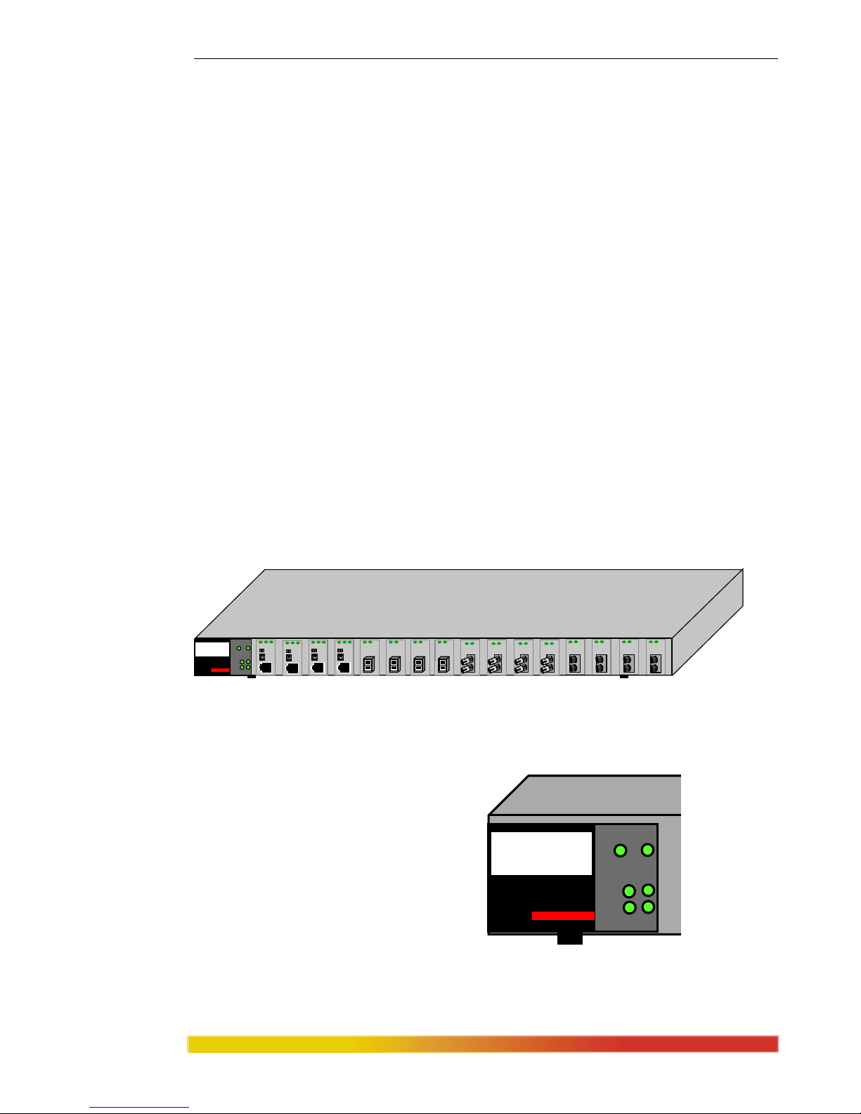
2.3.1 The Magnum 8000X Fiber Hub Chassis
The Magnum 8000X chassis houses one main PC board and an internal
bridge module (daughter board). There are 16 front slots for mixed-media modules.
Each front slot in the dual-speed chassis can accept any
8000X Port Module (PM)
which will provide either 10 or 100Mbps operation over either fiber or twisted pair
cabling. The 8000X is configured by selecting individual PMs, one per Ethernet port to
be used. Configured 8000X units provide two traffic domains, one each with IEEE
802.3 and 802.3u repeater functionality.
Figure 2.3.a: Magnum 8000X, Front View
LEDs to indicate operating status are on the left front side. There are power
(PWR) and bridge-inside (BR) indicators for the unit. There are collision (COL)
indicators for each of the 10 Mbps and
100Mbps domains for visual indication
of the operating status of each domain,
and two activity (ACT) indicators for
traffic activity on each domain. These
LEDs provide a visual assessment of the
operational condition and aggregate
network activity of all segments installed in the unit.Figure 2.3.b: Front Panel LEDs
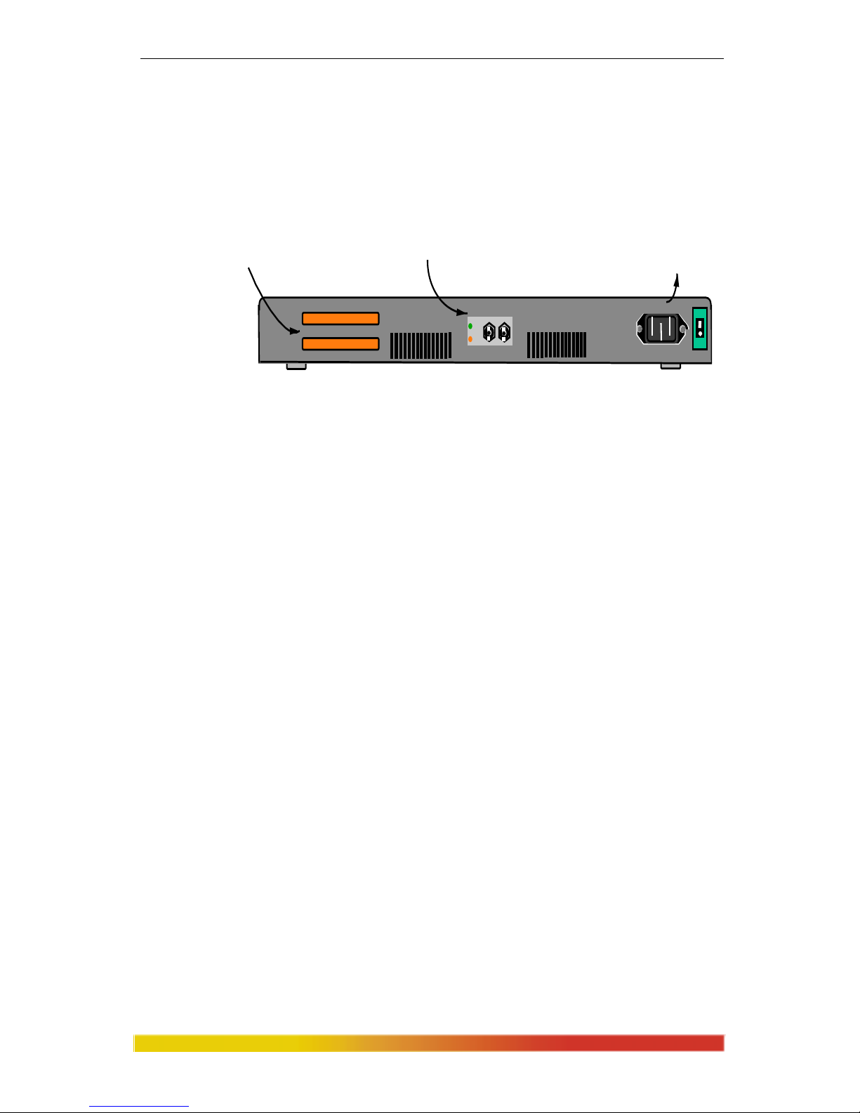
AC Power Connector: On the right side rear of the unit is the connection to
the auto-ranging internal power supply that automatically adapts to the AC voltage of
10 10 0
PWR BRD
ACT
COL
Magnum 8000X
Mixed Media Hub
GARRETT
1
R L SR L S
R L S
R L S R L
R L
R L
R LR L R L
R LR LR L
R LR L R L
10 100
A
CT
COL
Magnum 8000X
Mixed-Media Hub
PWR BRD
Page 15
Magnum 8000X Mixed-Media Fiber Hubs Installation and User Guide (05/ 02)
8
www GarrettCom com
..
the AC power system into which it is being installed. An ON/OFF power switch is used
for powering the hub on and off when it is placed in or taken out of service, or when it
needs to be reset. AC Power input is auto-ranging, from 100 to 240vac with a frequency
of 47
to 63 Hz. When shipped for use in U.S. and Canada, a 115vac power cord is included.
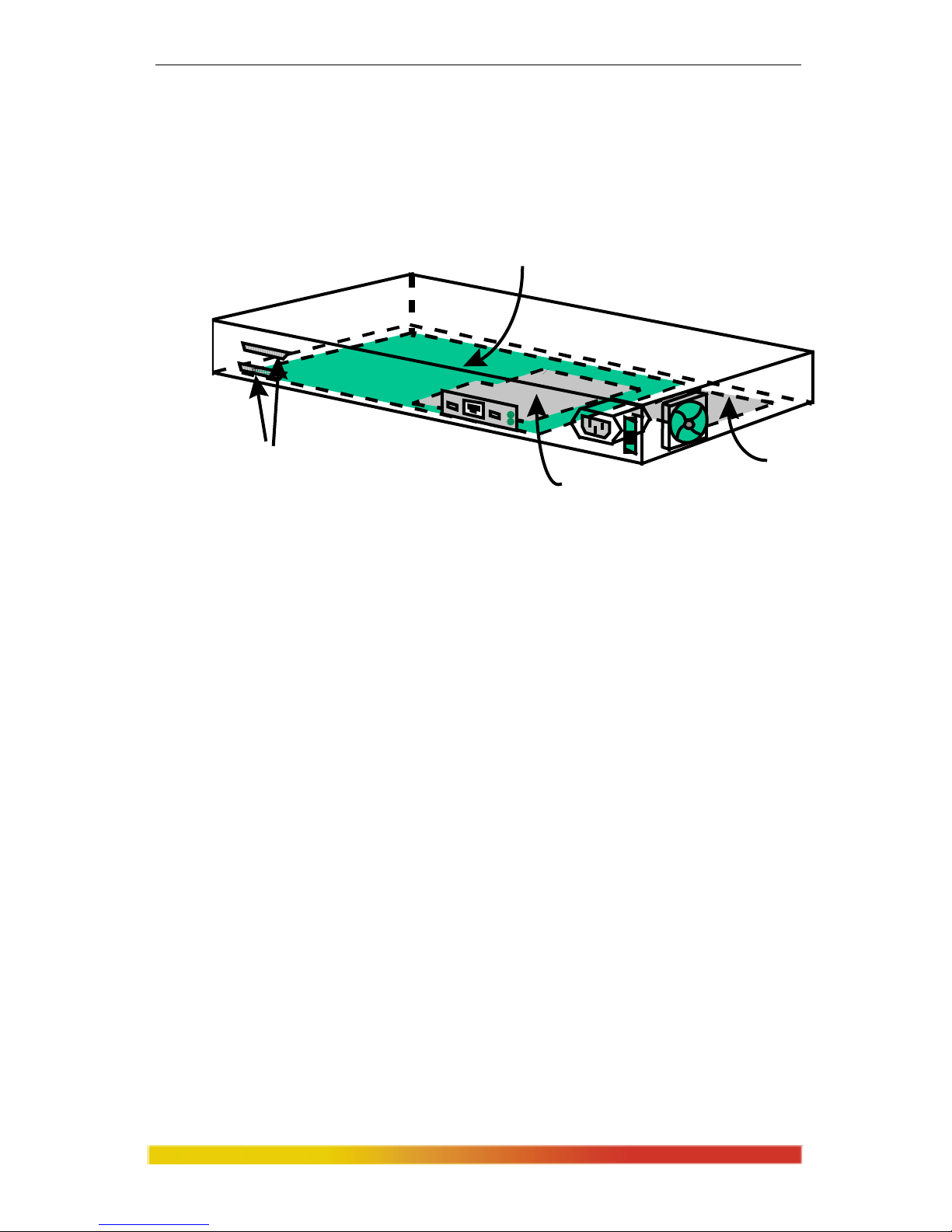
Figure 2.3.c: Magnum 8000X Rear Panel View
Cooling Fan: The Magnum 8000X is equipped with a low noise 9 cfm
fan. The fan will maintain low temperature operation inside the unit to
maximize reliability, even in wiring closets with ambient temperatures up to 50°C.
Bonus Port: The Magnum 8000X features a bonus port slot that is rear-
mounted and is optionally
configured with any one of the Switch Port Module (SPM)
types. An SPM will segment the 8000X from the other parts of the network connected
to it, providing flexibility in the network topology. This flexibility is especially
desirable for 100Mb traffic domains which are Path Delay Value (PDV) limited.
PMs for the front slots may not be used in the rear Bonus Port slot.
Inter-Repeater Bus (IRB): The IRB allows a Magnum 8000X unit to be
stacked with up to two Magnum 8000X-A and/or Magnum DS8016-A units to form
one logical dual-speed repeater. Instructions for the using the IRB connectors on the
Magnum 8000X are discussed in detail in Section 2.6, "Stacking Magnum 8000Xs".
2.4 Port Modules (PMs)
To provide maximum application flexibility, individual Port Modules
(PMs) are used with the Magnum 8000X. The Magnum 8000X features 16 PM slots on
the front of the unit and a bonus port slot on the rear of the unit, some (minimum of 2)
or all of which may
be configured at a given time. The bonus slot allows for an optional
rear-mounted switched Ethernet segment connection, typically to a backbone.With the
bonus slot, the 8000X becomes a 16-port dual-speed hub with one switched up-link.
There are a total of six standard PM cards, each for a specific media cable
connector. A seventh m
odule type is used as a face plate when any front slot is not
AC Powe r
Con ne c t o r
Bonus Port Sl ot, confi gurable vi a
Port Module ( PM)
(SPM - FST shown)
1 8
Inter-Repeater Bus (IRB)
P3 - Interface to unit above.
P4 - Interface to unit below.
R L
OUT
IN
ON
OFF
Page 16
Magnum 8000X Mixed-Media Fiber Hubs Installation and User Guide (05/ 02)
9
www GarrettCom com
..
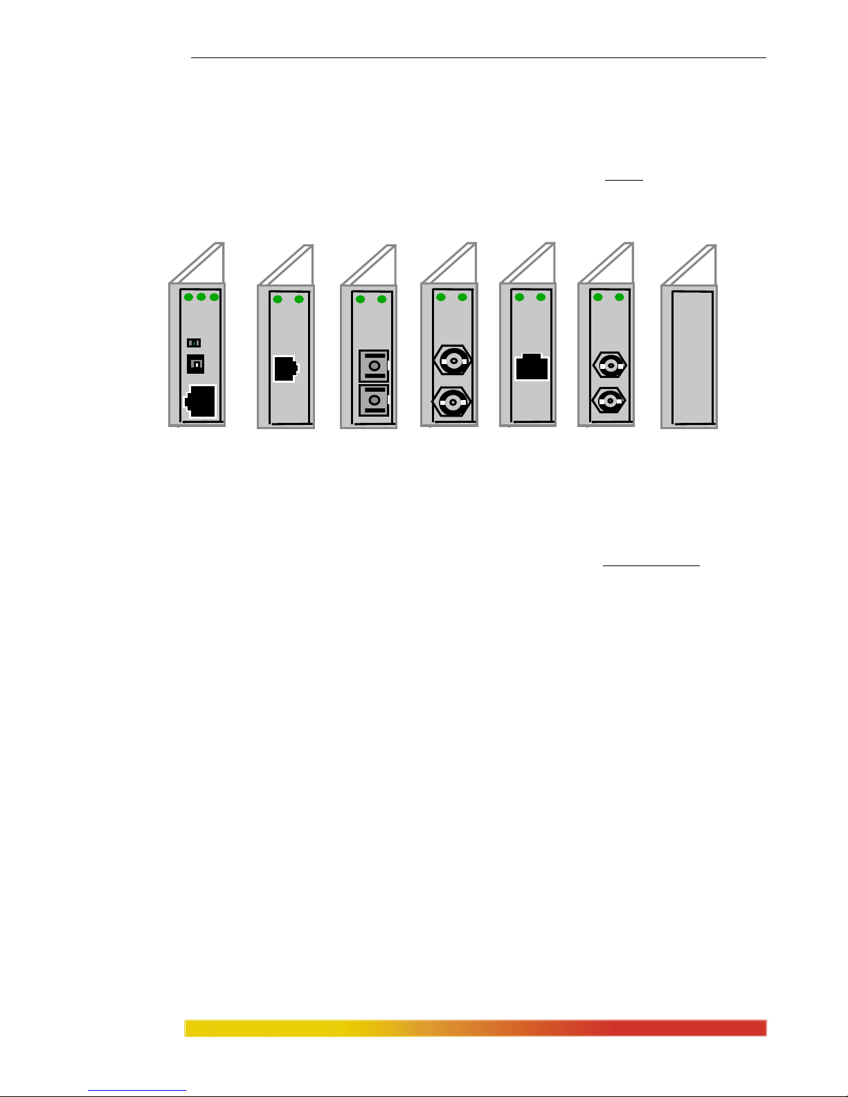
used. The Magnum 8000X PM network connector types, shown left-to-right in Figure
2.3a below, are “PM-RJ45U” for RJ-45s (10BASE-T or 100BASE-TX, UTP and STP)
with an up-link switch, “FPM-MTRJ” for fiber MT-RJ (small form factor 100BASE-FX
multi-mode), “FPM-MSC” for 100Mb fiber SC (100BASE-FX multi-mode) and same-
in-appearance “FPM-SSC” for 100Mb fiber SC (100BASE-FX single-mode), “FPM-
MST” for 100Mb FX fiber ST m.m., “FPM-MV45” for fiber VF-45 (small form factor
100BASE-FX multi-mode), the “FPM-SXMST” for 100BASE-SX (short-wavelength
Figure 2.4: Magnum Port Modules: PM-RJ45U, FPM-MTRJ,
FPM-MSC, FPM-MST, FPM-MV45, FPM-SXMST, & PM-FP
multi-mode ST), designed to be compatible with 10 Mbps FL, when available), and
“PM-FP” for the face plate to cover blank slots. PM-RJ-45 (not shown) looks like PM-
RJ45U but without the up-link switch. For additional details and descriptions of each
Port Module, see Section 5 of this manual.
PMs for other fiber port types (for example, 10 Mbps FC-type) are possible as
specials. If you need a different port type from those shown, contact GCI
Magnum PMs are normally installed in the front of Magnum 8000Xs at the
factory
prior to shipment, but may be installed or changed or removed in the field by a
careful technician. The PM removal / addition procedures are described in Section
5.2.1.- 5.2.7.
2.5 Switch Port Modules (SPMs)
Magnum Switch Port Modules (SPMs) provide a compact switching port that
filters and forwards packets, thus separating internal and external collision dom
ains and
enhancing the performance and configurability of the network. Unless specified at the
time of order, each Magnum 8000X is shipped from the factory with no bonus port
SPM installed. For application flexibility, any of the Magnum SPMs may be specified
1
A L S
A L A L
A L A L A L
Page 17
Magnum 8000X Mixed-Media Fiber Hubs Installation and User Guide (05/ 02)
10
www GarrettCom com
..
for factory configuration at time of order. It is also possible for the rear bonus port to be
re-configured in the field by a trained technician to add or exchange a Switching Port
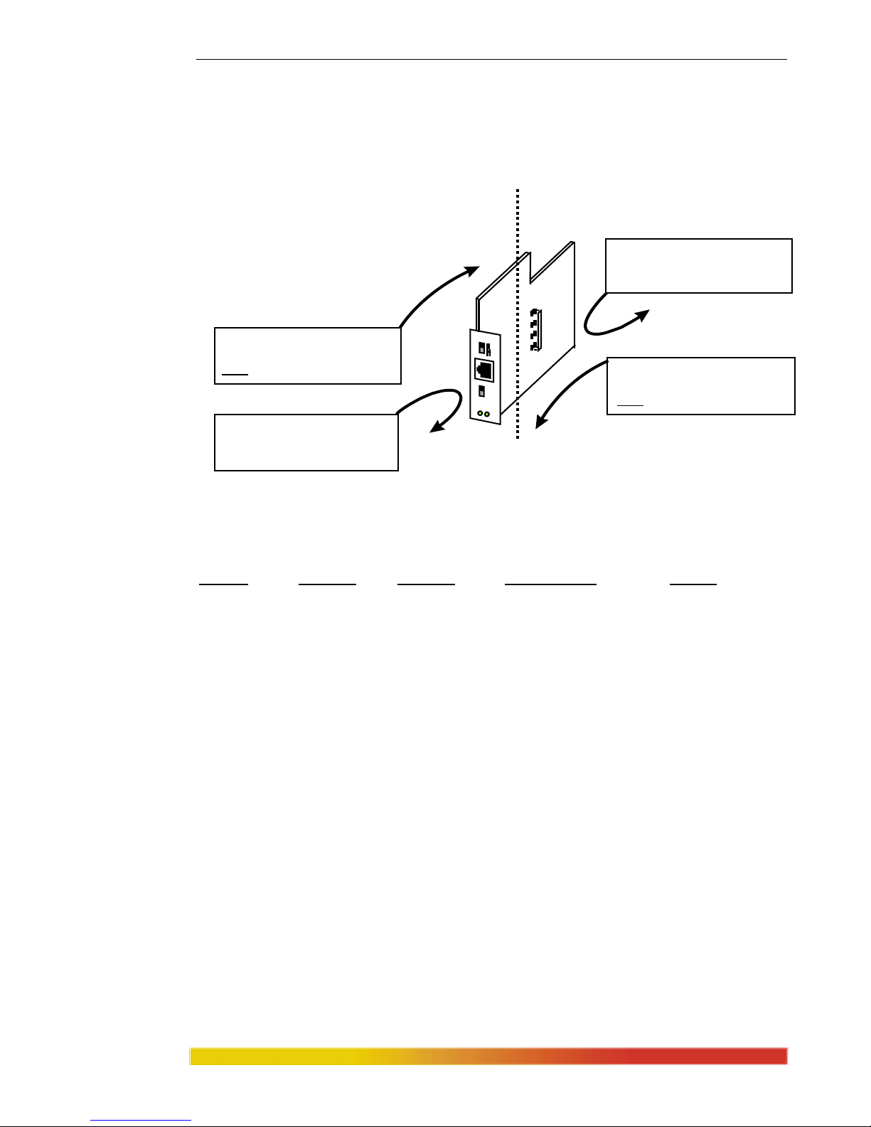
Module. Figure 2.5a below shows the internals of the Magnum 8000X with an SPM
installed in the Bonus Port, accessible from the rear.
Figure 2.5a: Inside view of Magnum 8000X with SPM installed. (Rear view)
For the specifications of available Switch Port Modules (SPMs), see Section
1.3. The functions of an SPM are described below.
1. Filtering and Forwarding / Address Learning
The SPM has two ports - one where media attaches, and one connecting into
the inside of the m
ixed-media fiber hub in which the SPM is mounted. For each packet
received by either port of the SPM, a decision is made to either filter the packet or to
forward the packet to the other port. Error packets are always filtered. For good packets,
the filter or forward decision is made based on the destination address contained in each
packet. If the destination address is on the segment from which the packet originated,
then it is filtered and not forwarded to the other segment. If the destination address
didn’t find a match in the address table, then is it forwarded to the other segment. If it is
a new address which the SPM didn’t previously didn’t know about, it “learns” the new
address and puts it in the port’s address table. The address tables have a capacity of 1K
addresses for each port.
MAIN BOARD
SPM
MODULE
POWER
SUPPLY
F
A
N
STACK ING
CONNECTO RS
Page 18
Magnum 8000X Mixed-Media Fiber Hubs Installation and User Guide (05/ 02)
11
www GarrettCom com
..
With this large address table, SPM port modules can serve the needs of
medium-sized to large networks. The address tables are flushed periodically to update
the network status and to purge any inactive stations from the tables. See the figure and
table that follows:
Packet Source Destination Address Table Filter/Forward
Source Address Address Maintenance Action
Seg. 1 Not in table Not in table Add source to table Forward
Seg. 1 Not in table In table Add source to table Filter
Seg. 1 In table Not in table None Forward
Seg. 1 In table In table None Filter
Seg. 2 Not in table Not in table Add source to table Forward
Seg. 2 Not in table In table Add source to table Filter
Seg. 2 In table Not in table None Forward
Seg. 2 In table In table None Filter
Table 2.5: SPM Port Module Functionality
2. Throughput Increase / Software Transparency
By selectively forwarding packets from the mixed-media hub’s ports (or hub stack’s
ports) to the rear-connector port based on its s
witching logic, an SPM increases the
available bandwidth for the users on both the hub side and the rear-segment side of the
network. As shown in Figure 2.5b, it keeps the local traffic on each side contained,
preventing unnecessary packets and bad packets from traveling to the other segment
and using up bandwidth needlessly. This results in more available network bandwidth
on both sides and a throughput increase for all users on both segments. An SPM needs
Figure 2.5b: Forwarding vs. Filtering in SPM Modules
Segment 1’s packets are forwarded
when the destination addresses are
NOT
in its address table.
Segment 2’s packets are forwarded
when the destination addresses are
NOT
in its address table.
Segment 1’s packets are filtered
when the destination addresses are
in its address table.
Segment 2’s packets are filtered
when the destination addresses are
in its address table.
SPM Module
100
1
0
Segment 1 Segment 2
(Bonus Port)
(Inside of Hub)
Page 19
Magnum 8000X Mixed-Media Fiber Hubs Installation and User Guide (05/ 02)
12
www GarrettCom com
..
no software configuring and is transparent to system and application software, including
network management software.
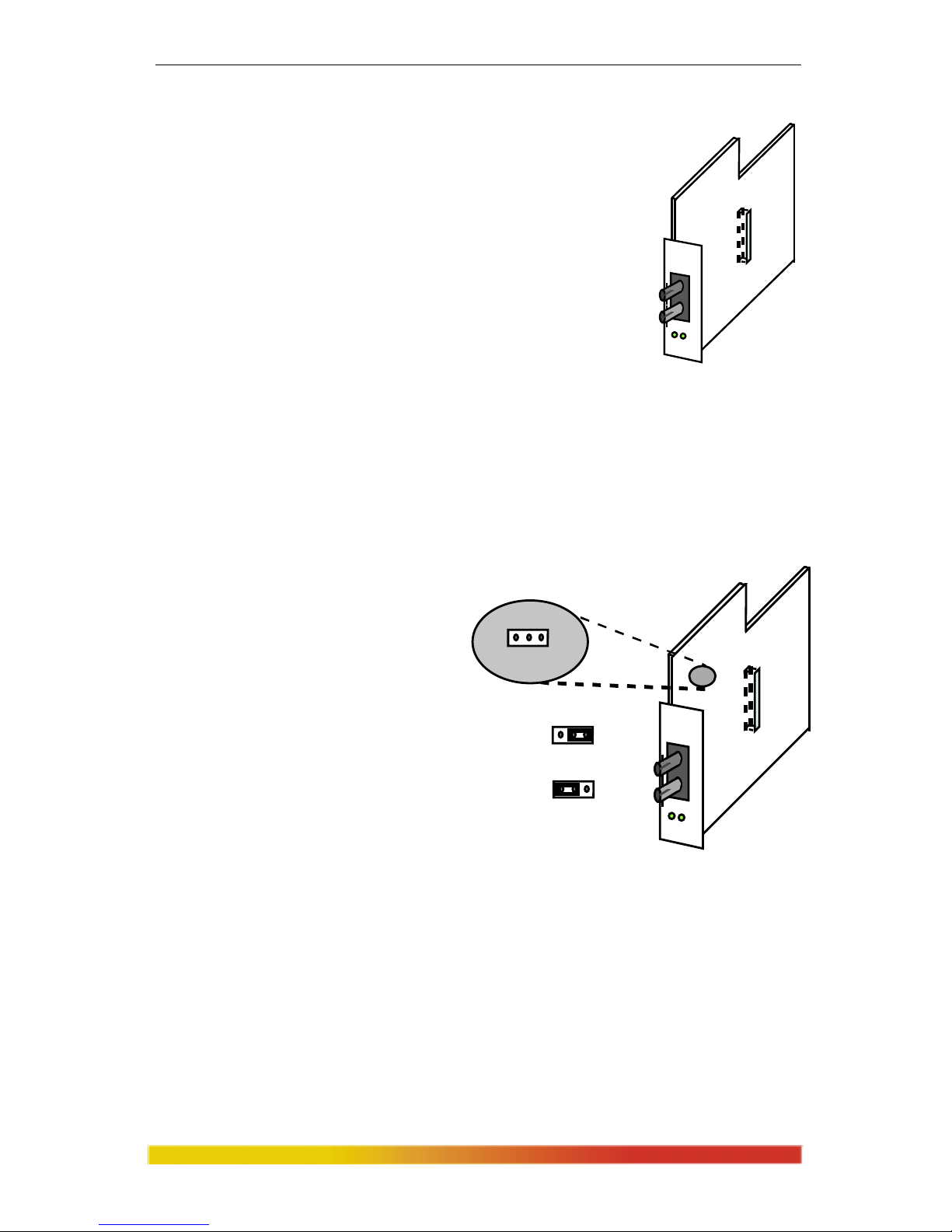
2.5.1 Magnum SPM-FDST
The significant feature of the SPM-FDST is that the fiber
bonus port operates in full-duplex mode, sending packets on
one fiber filament while simultaneously and independently
receiving packets on the other. There is no “collision
domain” with full- duplex, and while this violates the specs
of traditional Ethernet, it is accepted in most situations.
Therefore, the SPM-FDST extends the distance limits of Fast
Ethernet. In particular, with multi-mode fiber, it permits Fast
Ethernet cable distances of up to 2km, much more than the 412m half-duplex distance
limit otherwise obtainable.
These SPMs can also be configured to operate as a half-duplex switch port.
As shown in the figure, the jumper located on the SPM board by default is factory set
to full-duplex mode (position 2-3).
By setting the jumper in position 1-
2, it will operate as shared (half
duplex). To operate properly in
either half- or full-duplex mode, the
device on the other end of the fiber
segment must also be a
corresponding device. Since full-
duplex Fast Ethernet (802.3x) is a
recent 1997 standard, it is
recommended that the device on the
other end of the segment be another
full-duplex fiber SPM or equal.
As is typical for bridges and switches, the internal packet buffer space of the
SPM-FDST tem
porarily stores unfiltered packets. It is desirable to have a large packet
buffer for temporary storage, particularly when operating at different speeds (such as 10
and 100) or with different traffic types (shared and full-duplex). The SPM-FDST packet
Magnum SPM-FDST
R
X
L
I
N
K
F
U
L
L
D
U
P
L
E
X
Magnum SPM-FDST
R
X
L
I
N
K
F
U
L
L
D
U
P
L
E
X
HALF FULL
DUPLEX MODE
1
HALF FULL
1
HALF DUPLEX
HALF FULL
1
FULL DUPLEX
(Default)
FULL/HALF JUMPER
Page 20

Magnum 8000X Mixed-Media Fiber Hubs Installation and User Guide (05/ 02)
13
www GarrettCom com
..
buffer is 1Mbps to maintain high network performance. The MAC address memory is
8KB, suitable for medium to large networks.
In summary, the Magnum SPM-FDST is a multi-mode fiber optic switching
port module. It has 100Mb ST-type connectors. There are two LEDs, LINK and RX,
to allow monitoring of LINK and packet reception (Activity) status of the SPM. The
SPM may be used to connect to another full-duplex 100Mbps hub or switch using
fiber cabling and using the 100BASE-FX protocol. It filters and forwards packets in
both directions at Fast Ethernet wire speed.
2.5.2 Magnum SPM-FDSC
The Magnum SPM-FDSC is a multi-mode, full-
duplex fiber optic switching port module with a
100Mb SC-type connector. The module may be used
to connect to another 100Mbps hub or switch using
fiber cabling and the 100BASE-FX protocol. It filters
and forwards packets in both directions at Fast
Ethernet wire speed.
The operation and application of the SPM-
FDSC is the same as the SPM-FDST described
above, except for the connectors on the fiber cable.
2.5.3 Magnum SPM-FDSSC
The Magnum SPM-FDSSC is a single-mode, full-duplex fiber optic switching port
module with a 100Mb SC-ty
pe connector. The module may be used to connect to
another 100Mbps hub or switch using fiber cabling and
using the 100BASE-FX protocol. It filters and forwards
packets in both directions at Fast Ethernet wire speed.
Since the SPM module segments the network, it also
maintains its address tables to know what node
addresses are on which side of the unit.
The Magnum SPM-FDSSC includes full
switching functionality
and has two LED’s -
LINK and RX - to allow monitoring of link and
activity status of the SPM. The Magnum SPM-
FDSSC is a full duplex module. Thus, two
Magnum SPM-FDS
C
RX
LINK
F
X
SHARED
Magnum SPM-
FDSSC
RX
LINK
FX
SHARED
Page 21

Magnum 8000X Mixed-Media Fiber Hubs Installation and User Guide (05/ 02)
14
www GarrettCom com
..
SPM-FDSSC’s can be used together on each end of a fiber segment to get the
maximum distance of 15km of single-mode fiber optic cable in a Fast Ethernet
network. For an SPM-FDSSC used to connect into a separate collision domain,
the cable distances and hop-counts allowable would have to be calculated
taking into account all the devices’ Path Delay Values (PDVs) that are part of
that domain.
An SPM operating at 100Mbps has a PDV of 50 BT, i.e., the same PDV as a
DTE or NIC card in a Fast Ethernet collision domain.
2.5.4 Magnum SPM-TTX
The Magnum SPM-TTX is a 10 Mbps or 100Mbps device equipped with
one RJ-45 port which supports either 10BASE-T and 100BASE-TX. The
10/100 speed selection is done with a manual switch on
the unit to prevent ambiguity where it may be used with
other devices such as NICs that are auto-sensing.
The SPM-TTX filters and forwards packets, m
aintains
its address tables, and segments the network when used as a
10BASE-T or a 100BASE-TX switch port. See Sections 2.5 and
2.5.1 for a general description of an SPM. The SPM-TTX
includes an up-link switch to allow for connection to either user
nodes or for cascaded up-link connections to other hubs. The
attached devices may be either 10 Mb or 100Mbps.
The Magnum SPM-TTX has two LED’s - LINK and
RX - to allow monitoring of link and packet reception status of the SPM’s operation.
2.5.5 SPM Specification Summary Table
(See also “Specifications - SPMs,” Section 1.3)
Magnum SPM-TTX
100 10
M
b
/
s
U
P
L
I
N
K
R
X
L
I
N
K
Connector Standard Mb/s Traffic Pkt Buffer Address
SPM-FDST
Fiber-ST 100BASE-FX 100/200
full-duplex
1MB 8K total
SPM-FDST
Fiber-SC 100BASE-FX 100/200 full-duplex 1MB 8K total
SPM-SSC
Fiber-SC 100BASE-FX 100/200 full-duplex 1MB 8K total
SPM-TTX
RJ-45
10BASE-T & 100 -TX
10 or 100 shared 256KB 1024/port
Page 22

Magnum 8000X Mixed-Media Fiber Hubs Installation and User Guide (05/ 02)
15
www GarrettCom com
..
2.6 10 /100 Speed Auto-sensing (8000X front copper ports only)
Twisted pair copper ports (PM-RJ45 or PM-RJ45U only) support auto-
sensing for speed, independent of the other ports. Speed-sensing is performed by the
Magnum 8000X’s electronics in accordance with the standards of the IEEE 802.3u
auto-negotiation standard. If the connected device or node indicates that it is capable of
100Mbps speed, then operation on that port will be at 100Mbps. If the connected
device does not positively indicate that it is capable of 100Mbps speed, then the
operation on that 8000X port will be at 10Mbps. Of course, the hubs’ auto-negotiation
technique is only for 10 / 100 speed, and does not provide for any full-duplex operation.
When a twisted-pair port is connected and LINK is
present, the speed on that
port that has been sensed by the Magnum 8000X Mixed-Media Fiber Hub will be
indicated by the ‘S’ LED for that port. The ‘S’ LED is steady ON when 100Mbps speed
is sensed, and is steady OFF when 10Mbps speed is in use. When the port is not
connected, the ‘S’ LED on that port will be blinking to indicate that it is trying to auto-
negotiate. (See section 4.3 for the LED’s).
2.7 Stacking Magnum Mixed-Media 8000X Fiber Hubs
The rear of the Magnum 8000X Mixed-Media Fiber Hubs have an Inter-
Repeater Bus
(IRB) connector on the left side. The IRB interconnects stacked units with
a stacking cable, enabling all stacked Magnum 8000X units to operate as a single dual-
speed repeater. There are two 25-pin IRB connectors on each unit: the bottom IRB
connector which is used to daisy chain the IRB to the stacked unit below (unused on
bottom unit in a Magnum 8000X stack); and the top IRB connector which is used to
daisy chain the IRB to the stacked unit above (unused on top unit in a Magnum 8000X
stack). The IRB connectors for non-stacked units are unused.
The IRB stacking shielded cables supplied with each Magnum 8000X-A unit
are slightly
longer than the base unit height. The operation of the stack will not be
impaired by longer IRB RS232 cables. Stacks with total IRB lengths of as much as 9-
inch long shielded cables can be implemented. However, non-standard IRB cable
lengths, longer cables or unshielded cables are not permitted as they will not operate
properly at 100Mbps speeds.
The 8000X Mixed-Media Fiber Hub can be stacked with Magnum DS8016-A
m
odels, too. (But not with DS8016-B because of the “bridge-inside” conflict)
Page 23

Magnum 8000X Mixed-Media Fiber Hubs Installation and User Guide (05/ 02)
16
www GarrettCom com
..
Normally, one Magnum 8000X hub is needed to provide a switch between the 10 and
100Mbps domains.
With one base model Magnum 8000X, up to two additional 8000X-A “add-
on” units or two DS8016-A hub units can be stacked to operate as one 10/100 Dual-
Speed repeater with up to 48 dual-speed ports, with any mix of fiber and copper port
types.
When connecting mixed-media 8000X’s in a stack, use the stacking RS232
cable to connect the “OUT” stacking port from one 8000X unit to the “IN” stacking
port of the other. Push in the cable connectors until they
seat in firmly. Also, leave
space along the left-side area for the exhaust of the internal cooling fan in each 8000X
unit.
Figure 2.7b Magnum 8000X’s stacked. Cables connect “Out” and “In”
2.8 Bridge Module between the 10 Mbps and 100Mbps Domains
Magnum 8000X’s contain a factory-installed bridge module to interconnect
the two traffic domains, filtering and selectively forwarding packets to allow only
necessary packets to cross between the domains. This enables all of the users and nodes
connected into either domain, whether 100Mbps or 10 Mbps , to communicate to each
other, and it keeps local traffic on one domain from consuming any of the bandwidth of
the other domain.
Fig.2.7a A stack of one Magnum 8000X and two DS-8016-A’s
10 100
PWR BRD
ACT
COL
Magnum 8000X
Mixed Media Hub
GARRETT
1
R L SR L S
R L S
R L S R L
R L
R L
R LR L R L
R LR LR L
R LR L R L
1 2 3 4 5 6 7 8 9 10 11 12 13 14 15 16
1 X
LK/RX
PORT
100
1
2 3 4 5 6 7 8 9 10 11 12 13 14 15 16
PWR
BR
COL 10
COL 100
Magnum DS8016 Stackable Hub
1 2 3 4 5 6 7 8 9 10 11 12 13 14 15 16
1 X
LK/RX
PORT
100
1
2 3 4 5 6 7 8 9 10 11 12 13 14 15 16
PWR
BR
COL 10
COL 100
Magnum DS8016 Stackable Hub
IN
ON
OFF
BONUS PORT
IN
IN
ON
OFF
BONUS PORT
ON
OFF
BONUS PORT
FAN
EXHAUST
OUT
IN
OUT
IN
OUT
IN
Page 24

Magnum 8000X Mixed-Media Fiber Hubs Installation and User Guide (05/ 02)
17
www GarrettCom com
..
The bridge operates in the store-and-forward mode, which filters out bad
packets and maintains optimum performance in both domains. Packet forwarding delay
is only 5µs (plus packet time), much less than traditional store-and-forward bridge
products, enabling the 8000Xs to maintain high network performance. The bridge has
8K node address capacity, suitable for use in large networks. Addresses are self-
learning so that filtering / forwarding of 10 Mbps and of 100Mbps packets is
maintained correctly even when users move their connection, or change speed, or power
down.
Figure 2.8 : Internal view of 8000X with bridge module installed
The Magnum 8000X’s bridge module is implemented as a daughter board. 8000X units
have an LED on the front labeled BR that will be ON when the module is installed
internally. (The Model 8000X-A is an “add-on” unit for stacking, and has no bridge
inside, so it’s BR LED will be off). In a stack of Magnum 8000X’s and / or other
compatible hubs, only one unit with a bridge inside may be operating in any one stack.
Bridge Module
Page 25

Magnum 8000X Mixed-Media Fiber Hubs Installation and User Guide (05/ 02)
18
www GarrettCom com
..
2.9 Features and Benefits
! Supports 10 or 100Mb network connections on each of sixteen ports
Magnum 8000X Dual-Speed Fiber Hubs combine two logical hubs --- one at 10 Mbps
and one at 100Mbps --- in one physical box supporting two traffic domains. Each port
can operate at either 10 or 100Mbps, independently of the other ports.
! Mixed-Media 10 & 100Mb fiber port ty
pes in one unit for maximum flexibility
The Magnum 8000X is configurable with up to 16 economical port modules, and any or
all of the ports may be either 10 or 100Mbps fiber. RJ-45 ports may also be configured,
with per-port selection. Port Modules with all kinds of fiber connector types are
supported, making the 8000X Fiber Hub ideal for “fiber-to-the-desktop” applications.
! Switched port in the rear Bonus Port for a FDX fiber backbone, optional
To segment a Magnum 8000X (or stack) from a connected hub or switch using full-
duplex fiber operating at 100Mbps, an optional SPM may be installed. This provides
distances up to 2Km for the fiber link, and improved performance for the 8000X’s
users.
! Stackable and Scaleable Configurations
The Magnum 8000X is equipped with an inter-repeater bus that allows multiple units
(one 8000X and up to two 8000X-A units or two DS8016-A) to be stacked, thus
supports up to 48 ports with all ports operating as a single dual-speed mixed-media
repeater.
! Auto-sensing for speed, 10 or 100Mbps, on each RJ-45 front port
All RJ-45 ports support 10/100 auto-negotiation for speed, IEEE802.3u. compliant.
! LEDs for Chassis and PM Cards
The Magnum 8000X chassis and each of the 16 front-mounted PM cards are equipped
with traffic activity and segment-status LEDs, conveniently monitored from the front.
! Installation is “Plug and Play”, Operation is Transparent to Softw
are
The Magnum 8000X operates as a hardware switch between domains, only forwarding
those packets from each domain that are needed on the other domain. Internal address
tables are self-learning, enabling users to change port connections or 10 or 100Mbps
domains without affecting operations.
! Inte
rnal Power Supply, Auto-ranging AC voltage and frequency
An internal universal power supply allows any Magnum 8000X unit to be used with the
normal AC power types found around the world. (A 48VDC power supply is optional)
Page 26

Magnum 8000X Mixed-Media Fiber Hubs Installation and User Guide (05/ 02)
19
www GarrettCom com
..
2.10 Applications
The 8000X Port Modules are factory and field configurable. This (and the
stacking feature) provides for easy expansion of the network, and it provides flexibility
to adapt to new fiber port connector types as technology changes. The flexibility of the
Magnum 8000X makes it the choice for applications that require a flexible and
adaptable 10/100 hub.
See also Section 1.0, Technical Specifications, for additional Magnum 8000X
inform
ation that may indicate suitable applications.
Example 1: Upgrade, Expansion, Fiber Flexibility : A University
library has fiber
cabling installed in the building from the wiring closet to each PC. They have operated
the network setup at 10 Mbps. They have five users, a 10Mbps print server, and
Internet access. Now they require higher bandwidth to accelerate their network. They
want to upgrade three of their present users to 100Mbps speed and expand for another
five 100Mbps users (all with fiber), and they expect a few more users next year.
A Magnum 8000X Dual-Speed Fiber Hub handles all of the users at 10 Mbps
and 100Mbps over fiber and copper in the same hub unit. Port modules can be changed
or added over tim
e to suit expansion and additional changes. The 8000X is initially
configured with eight ports at 100Mbps fiber, two ports at 10Mbps fiber, and three
10/100 RJ-45 copper ports. The Magnum 8000X not only increases the network’s
bandwidth and efficiency, but it also handles existing 10Mbps nodes over fiber in a
economical way. The print server stays at 10Mbps over twisted pair wiring, and is
accessible by all users. The file server and the Internet access, devices located adjacent
to the 8000X, operate over twisted pair at 100Mbps.
A diagram of the installation is shown here.
Example 2: Security, Fiber Flexibility: In a governm
ent intelligence agency where a
secure network is the first priority, the possibility of eavesdropping (as is possible with
copper wiring) must be prevented. Fiber LANs are regularly used to connect to each
desktop and each node.
Magnum 8000X configured here with
8 100Mb fiber, 2 10Mb fiber, 3 10/100 RJ-45
Print Server
10
UPLINK
Server
Router
100
100
100
100
100
100
100
100
100
8 100Mb fiber segments
1
0
0
M
b
R
J
-
4
5
10Mb RJ-45
Magnum ST80-F
1
0
M
b f
i
be
r
Page 27

Magnum 8000X Mixed-Media Fiber Hubs Installation and User Guide (05/ 02)
20
www GarrettCom com
..
The Magnum 8000X Fiber Hubs support all of the fiber port types (including the latest
models), adapting the fiber LAN to changing technology. The Dual- Speed feature
provides for growth in performance to higher bandwidth 100Mbps speed, and the perport modularity plus stacking provide for port expansion.
Example 3: Future-proofing, industrial environments: In heavy industrial plants
(such as steel mills, electrical generating stations, telecom central offices, hospitals,
etc.), fiber LAN cables are usually used for noise immunity and electrical groundisolation. In this kind of environment where computer systems are used to monitor and /
or manage operations, an Ethernet fiber link is used to collect real-time data via SNMP
agents in the equipment. The SNMP management fiber network almost always operates
at 10 Mbps. Network management workstations and network servers use 100Mbps
ports to the high performance nodes.
The Magnum 8000X Dual-Speed Fiber Hub is ideal in these situations. The
fiber ports are economical and may
be a mix of 10 and 100Mbps, and may be any
quantity or mix of standard port connector types. Individual 10/100 RJ-45 ports may be
configured also, and an optional SPM can segment local users from the rest of the
network. Stacking provides capacity for up to 48 ports, and the 8000X can be stacked
with a DS8016-A for a mix of RJ-45 and fiber ports. The flexibility results in a
“future-proof” fiber hub. The illustration below shows this type of installation.
Magnum 8000X has 16 ports per unit,
is stackable u
p
to 3 units, and economicall
y
supports all fiber types to the desktop for
maximu
m
security and flexibilit
y
.
Server
100
100
100
100
100
100
Router
Print Server
Fiber segments, 100Mb or 10Mb
Magnum 8000X offers a full range of fiber port
modules (both 10Mb and 100Mb), 10/100 RJ-45,
and stackability for the ultimate in “future-proofing”,
even noisy specialty environments
Server
100
100
100
100
100
100
Router
Print Server
Magnum DS80
101/00 Personal Hub
10BASE-FL
Fiber Segment
1
0
10
100
100
Page 28

Magnum 8000X Mixed-Media Fiber Hubs Installation and User Guide (05/ 02)
21
www GarrettCom com
..
3.0 Magnum 8000X Installation
Before installing the equipment, it is necessary to take the
following precautions:
1.) If the equipment is mounted in an enclosed or multiple rack
assembly, the environmental temperature around the equipment
must be less than or equal to 50
0
C.
2.) If the equipment is mounted in an enclosed or multiple rack
assembly, adequate air flow must be maintained for proper and
safe operation.
3.) If the equipment is mounted in an enclosed or multiple rack
system placement of the equipment must not overload or load
unevenly the rack system.
4.) If the equipment is mounted in an enclosed or multiple rack
assembly, verify the equipment’s power requirements to prevent
overloading of the building/s electrical circuits.
5.) If the equipment is mounted in an enclosed or multiple rack
assembly verify that the equipment has a reliable and
uncompromised earthing path.
Installation: This section describes installation of the Magnum Mixed-Media 8000X
Hub, as well as connection of the various Ethernet media types.
3.1 Locating the Magnum 8000X
The location of the Magnum 8000X is dependent on the physical layout of the
network and the area to be served. The unit is ty
pically rack mounted in a
wiring closet but because it has rubber feet it can also be installed on a shelf
or table top. While stacks of up to 3 units and the associated cabling can be
accommodated on a shelf or table top, it is recommended that larger stacks be
rack mounted. Each unit is shipped with a pair of metal "ears" that attach to
each side of the unit to easily accommodate mounting in standard 19"
RETMA racks. (Brackets for 23” telco racks are optional at extra cost).
3.2 Connecting Ethernet Media
The Magnum 8000X Mixed-Media Fiber Hub is specifically
designed to support all standard Ethernet media ty
pes within a single hub
unit. This is accomplished by using a family of Port Modules (PMs) which
can be individually selected and configured per-port. See Section 2.4 for a
description of the PMs.
Page 29

Magnum 8000X Mixed-Media Fiber Hubs Installation and User Guide (05/ 02)
22
www GarrettCom com
..
The various media types supported along with the corresponding IEEE
802.3 and 802.3u standards and connector types are as follows:
IEEE Standard Media Type Max. Distance 8000X Port Module
Fiber:
10BASE-FL mm
1
Fiber 2.0km(6562 ft) FPM10-MST, FPM10-MSC
sgl.m
2
Fiber 10.0km(65620ft) FPM10-SST, FPM10-SSC
100BASE-FX
mm1 Fiber 200 m
3
(650 ft) FPM-MSC, FPM-MST
small form factor “ “ FPM-MTRJ, FPM-MV45
sgl.m
2
Fiber 200 m
3
(650 ft) FPM-SSC
100BASE-SX (proposed, 850nm mm1) 150 m3 (500 ft) FPM-SXMST, -SXMSC -
short wavelength
Copper:
10BASE-T & 100BASE-TX twisted pair 100m (328 ft) PM-RJ45, PM-RJ45U
1
mm = multi-mode
2
sgl.m = single-mode
3
max. each for two segments in a 100Mb collision domain. Single segment is 412m for FX and 300m for
SX.
3.3 Connecting Fiber Optic ST-type, “twist-lock”
The following procedure applies to installations using an PM with
ST-type fiber connectors. This procedure applies to ports using an FPM-MST,
FPM10-MST, FPM10-SST single-mode, FPM-SXMST, and to SPM-FDST.
1. Before connecting the fiber optic cable, remove the protective dust caps from
the
tips of the connectors on the FPM. Save these dust caps for future use.
2. Wipe clean the ends of the dual connectors with a soft cloth or lint-free lens
tissue dampened in alcohol. Make certain the connectors are clean before
connecting.
Note: One strand of the duplex fiber optic cable is coded using color
bands at regular intervals; you must use the color-coded strand on the
associated ports at each end of the fiber optic segment.
3. Connect the Transmit (TX) port (light colored post) on the Magnum FPM to the
Receive (RX) port of the remote device. Begin with the color-coded strand of
the cable for this first TX-to-RX connection.
4. Connect the Receive (RX) port (dark colored post on the PM) to the Transmit
(TX) port of the remote device. Use the non-color coded fiber strand for this.
5. The LINK LED on the front of the PM will illum
inate when a proper connection
has been established at both ends (and when power is ON in the unit). If LINK
is not lit after cable connection, the normal cause is improper cable polarity.
Swap the fiber cables at the Port Module connector to remedy this situation.
3.4 Connecting Fiber Optic SC-type, "Snap-In"
The following procedure applies to installations using an PM with SC-type
fiber connectors. This procedure applies to ports using an FPM-MSC, FPM-SSC single-
mode, FPM10-MSC, FPM10-SSC, FPM-SXMSC, and to SPM-FDSC and -FDSSC
single-mode.
Page 30

Magnum 8000X Mixed-Media Fiber Hubs Installation and User Guide (05/ 02)
23
www GarrettCom com
..
When connecting fiber media to SC connectors, simply snap on the two
square male connectors into the SC female jacks of the PM until it clicks and secures.
3.5 Connecting Single-Mode Fiber Optic
When using single-mode fiber cable, be sure to use single-mode
fiber port connectors. Single-mode fiber cable has a smaller diameter than multi-mode
fiber cable (9/125 microns for single-mode, 50/125 or 62.5/125 microns for multi-mode
where xx/xx are the diameters of the core and the core plus the cladding respectively).
Single-mode fiber allows full bandwidth at longer distances, and may be used to
connect 10Mb nodes up to 10 Km apart, or 15Km with the SPM-FDSSC.
The same procedures as for multi-mode fiber applies to single-m
ode fiber connectors.
Follow the steps listed in Section 3.3 and 3.4 above.
3.6 Connecting Twisted Pair (RJ-45,CAT3,
CAT5, Unshielded or Shielded)
The RJ-45 ports of the Magnum 8000X Dual-Speed Hubs can be connected to
the following two media ty
pes: 100BASE-TX and 10BASE-T. CAT 5 cables should be
used when making 100BASE-TX connections. When the ports are used as 10BASE-T
ports, CAT 3 may be used. In either case, the maximum distance for unshielded
twisted pair cabling is 100 meters (328 ft).
Media IEEE Standard Connector
Twisted Pair (CAT 3, 4, 5) 10BASE-T RJ-45
Twisted Pair (CAT 5) 100BASE-TX RJ-45
NOTE : It is recommended that high quality CAT. 5 cables (which work for both
10Mb and 100Mb) be used whenever possible in order to provide flexibility in
a mixed-speed network, since dual-speed ports are auto-sensing for either 10
and 100Mb/s.
The following procedure describes how to connect a 10BASE-T or
100BASE-TX twisted pair segment to the RJ-45 port. The procedure is the
same for both unshielded and shielded twisted pair cables.
1. Using standard twisted pair media, insert either end of the cable with an RJ
-45
plug into the RJ-45 connector of the port. Note that, even though the connector
is shielded, either unshielded or shielded cables and wiring may be used.
2. Connect the other end of the cable to the corresponding device
3. Use the LINK LED to ensure proper connectivity
by noting that the LED will be
illuminated when the unit is powered and proper connection is established
Page 31

Magnum 8000X Mixed-Media Fiber Hubs Installation and User Guide (05/ 02)
24
www GarrettCom com
..
4. For Port #1, if the LINK LED is not illuminated, change to port 1X. If this does
not help, ensure that the cable is connected properly and that the device on the
other end is powered on and is not defective.
3.6.1 100Mbps Collision Domain Diameter, Cable Distances and PDV
Calculations
The 100Mbps Collision Domain Diameter is the length of the longest path
between any
two devices in a single collision domain. A collision domain is defined as
a cluster of network devices which are connected by means of a repeater or repeaters
such that no bridging devices are present between any two devices in the cluster. In
order to install an IEEE 802.3u compliant Fast Ethernet network, the collision domain .
. regardless of the actual network topology . . must be less than 512 BT (Bit Times).
Bit Times are related to media type as shown in Table 3.6.1a.
Table 3.6.1a: Worst case round-trip delay for Fast Ethernet media*
Media Type Round-trip delay in
Bit Time per Meter (BT/m)
Fiber Optic 1.000
Shielded TP cable 1.112
Category 5 Cable 1.112
Category 3, 4 Cable 1.140
*Worst case delays taken from IEEE Std 802.3u-1995, actual delays may be less for a particular
cable. Contact your cable supplier for exact cable specifications.
Each Fast Ethernet device component also has an associated BT delay which
depends on the physical signaling system employed. Table 3.6.1b shows each Fast
Ethernet device component and the associated BT delay. A “DTE” is an end node, such
as a user station. Note that there is only one DTE pair associated with any device-to-
device path.
Table 3.6.1b: Worst case round-trip delay for Fast Ethernet device components*
Component Round-trip delay in Bit Times (BT)
2 TX DTEs 100
2 FX DTEs 100
1 FX and 1 TX DTE 100
1 T4 and 1 TX or FX DTE 127
Class I Repeater 140
Class II Repeater with any
combination of TX and FX ports
92 **
**Note, the delay is only 80 Bit Times for
the 8000X, front-port-to-front-port.
*Worst case delays taken from IEEE Std 802.3u -1995.
Page 32

Magnum 8000X Mixed-Media Fiber Hubs Installation and User Guide (05/ 02)
25
www GarrettCom com
..
To determine whether a prospective network topology adheres to the collision
domain diameter specification, the following formula should be applied to the worst
case path through the network. The worst case path is the path between the two Fast
Ethernet devices (DTEs) which have the longest round-trip time.
PDV = (sum of cabling delays) + (sum of repeater delays) +
(DTE pair delay) + (safety margin)
PDV is the Path Delay Value of the worst case path. For the network to
adhere to IEEE standard, this value m
ust be less than 512 BT. The safety margin is
specified in BT and may be a value between 0 and 5. This margin can be used to
accommodate unexpected delays such as extra long patch cable. A safety margin of
about 2 to 4 BT is recommended.
A typical example of a PDV calculation is shown below, and is illustrated in
Figure 3.6.1a. Here, an integrator wishes to cascade the 100Mbps collision dom
ains of
two Magnum 8000X Mixed-Media Hubs (each having a PDV of 80 BT) for use with
standard 100m Category 5 user cable segments (i.e. from computer to hub) and needs to
know how long the inter-repeater Category 5 cable segment, used to cascade the hubs,
can be. The variable “X” represents the unknown maximum cascade cable delay.
PDV = X + ((111 + 111) + (80 + 80) + (100) + 2 ) BT < 512 BT
512 > (X + 486) BT
X < (512 - 486 ) BT, X < 28 BT
Twisted Pair cable length, TL < (28 BT) / (1.112 m/BT)
TL < 25 meters
⇒ 25 m maximum total length for Category 5 inter-repeater segment,
where 111 is the BT delay for 100m of Category 5 cable (1.112 BT/m* 100m), 80 is the
BT delay for each Magnum 8000X , 100 is the BT delay for the TX DTE pair, and a
safety margin of 2 was used. Figure 3.6.1a: Two cascaded Magnum 8000X hubs
100 m Cat. 5 cables
to user devices
100 m Cat. 5 cables
to user devices
Cat. 5 cable for
cascading
1010 0
PWR BRD
ACT
COL
Magnum 8000X
Mixed Media Hub
GARRETT
1
R L SR L S
R L S
R L S R L
R L
R L
R LR L R L
R LR LR L
R LR L R L
1010 0
PWR BRD
ACT
COL
Magnum 8000X
Mixed Media Hub
GARRETT
1
R L SR L S
R L S
R L S R L
R L
R L
R LR L R L
R LR LR L
R LR L R L
Page 33

Magnum 8000X Mixed-Media Fiber Hubs Installation and User Guide (05/ 02)
26
www GarrettCom com
..
The resulting value tells us that a Category 5 cable with a length of up to 25
meters may be used to cascade the Magnum 8000Xs. Note that this inter-repeater cable
length may be increased by shortening the lengths of the 100m hub-to-user cable
segments.
It is also possible to cascade a group of up to nine Magnum 8000Xs (serving
up to 56 users with full-length 100m cables to each) by using short inter-repeater cable
segments. The following is an example of how to calculate the maximum allowable
cascade cable segment length. An illustration of this example is shown in Figure 3.6.1b,
where the hub-to-user cable lengths are up to 75 meters for Cat 5 twisted pair. The
variable “X”, the maximum hub-to-hub cable delay, is calculated as follows:
PDV = X + ((100) + (80 + 80 + 80 )+ (83 + 83) + 2 ) BT < 512 BT
512 > (X + 508) BT, X < 4 BT
Twisted pair user cable length, TL < (4 BT) / (1.112 m/BT)
TL < 3.6 meters for two hub-to-hub cascading cables
⇒ 2 meters (6 ft.) length max. for each of the cascade segments,
In the above example, 75 is the BT delay for 70m of Category
5 cable (1.112 BT/m), 80
is the bit time delay for each Magnum 8000X front-to-front ports, 100 is the BT delay
for the TX DTE pair in the user
stations, and 2 BT is the safety margin
applied.
Figure 3.6.1b: Multiple cascaded
Magnum 8000X
Mixed-Media hubs
Note that the cascading of multiple
Magnum 8000X Mixed-Media hubs is a
capability
beyond what industry
standards normally permit, and is different from what competitive 100Mbps Class II
hub products normally allow. This additional cascading level and cable length is due to
the relatively shorter bit time (80 BT actually measured, for front-port-to-port) delay of
the Magnum 8000X vs. the industry standard delay of 92 BT for Class II repeaters. The
installation flexibility and network growth potential is accordingly better with Magnum
8000Xs than with hubs that merely meet the standard. Table 3.6.1c shows maximum
cable lengths for common network configurations using industry standard repeater PDV
numbers. Calculations such as above should be performed using measured PDV data
supplied by the equipment manufacturer in important installations.
2 meter Cat. 5 cable
for cascadi ng
All user devices connected
via Cat. 5 twisted pair cable
of up to 75m length.
10100
PWR BRD
ACT
COL
Magnum 8000X
Mixed Media Hub
GARRETT
1
R L SR L S
R L S
R L S R L
R L
R L
R LR L R L
R LR LR L
R LR L R L
10100
PWR BRD
ACT
COL
Magnum 8000X
Mixed Media Hub
GARRETT
1
R L SR L S
R L S
R L S R L
R L
R L
R LR L R L
R LR LR L
R LR L R L
10100
PWR BRD
ACT
COL
Magnum 8000X
Mixed Media Hub
GARRETT
1
R L SR L S
R L S
R L S R L
R L
R L
R LR L R L
R LR LR L
R LR L R L
Page 34

Magnum 8000X Mixed-Media Fiber Hubs Installation and User Guide (05/ 02)
27
www GarrettCom com
..
Table 3.6.1c: Maximum segment lengths for common network configurations
Number
of Hubs
Repeater
Hop Count
Max. User
Segment
Lengths (m)
Max. Inter-
Repeater (Cascade)
Length (m)
Notes
1 1 100.0 n.a. All ports TX
2 2 100.0 5.0 All ports TX
2 2 92.0 20.0 All ports TX
3+ 3 60.0 1.0 All ports TX
Instructions for connecting the Magnum 8000X Mixed-Media Hubs to the
various Fast Ethernet media are given in the following sections.
3.6.2 Connections to NICs which support Auto-Negotiation
The Magnum 8000X Mixed-Media Hub will function properly with NICs
(Network Interface Cards) which support Auto-Negotiation. The Magnum
8000X will
establish link with any NIC which can send and receive the Fast Link Pulse (FLP)
coding for the 100BASE-TX signaling system. When connecting a NIC to the 8000X, it
may be necessary to reload the NIC drivers on the user device if the NIC has been
communicating with a protocol other than 100BASE-TX (such as 10BASE-T). When
100Mb operation is agreed and in use, the 100Mb LINK/ACT LED is illuminated,
steady ON if no traffic or blinking when there is traffic.
3.7 Table-Top or Shelf Mounting
The Magnum 8000X fiber Hub can be easily
mounted on a table-top or any
suitable horizontal surface, and has four rubber feet to provide stability without
scratching finished surfaces.
3.8 Rack-Mounting
Installation of a
Magnum 8000X mixed-
media fiber Hub in a 19” rack is a simple procedure. The units are 1U (1.70”) high.
When properly
installed, the front-mounted LED status indicators should be in plain
view and easy to read. Rack-mount installation requires special 19” rack-mounted
brackets and screws (included with each 8000X unit). The brackets attach to the front
sides of the hub, which is then fastened into a standard 19” RETMA rack.
10100
PWR
BRD
ACT
COL
Magnum 8000X
Mixed Media Hub
GARRETT
1
R L SR L S
R L S
R L S R L
R L
R L
R LR L R L
R LR LR L
R LR L R L
Page 35
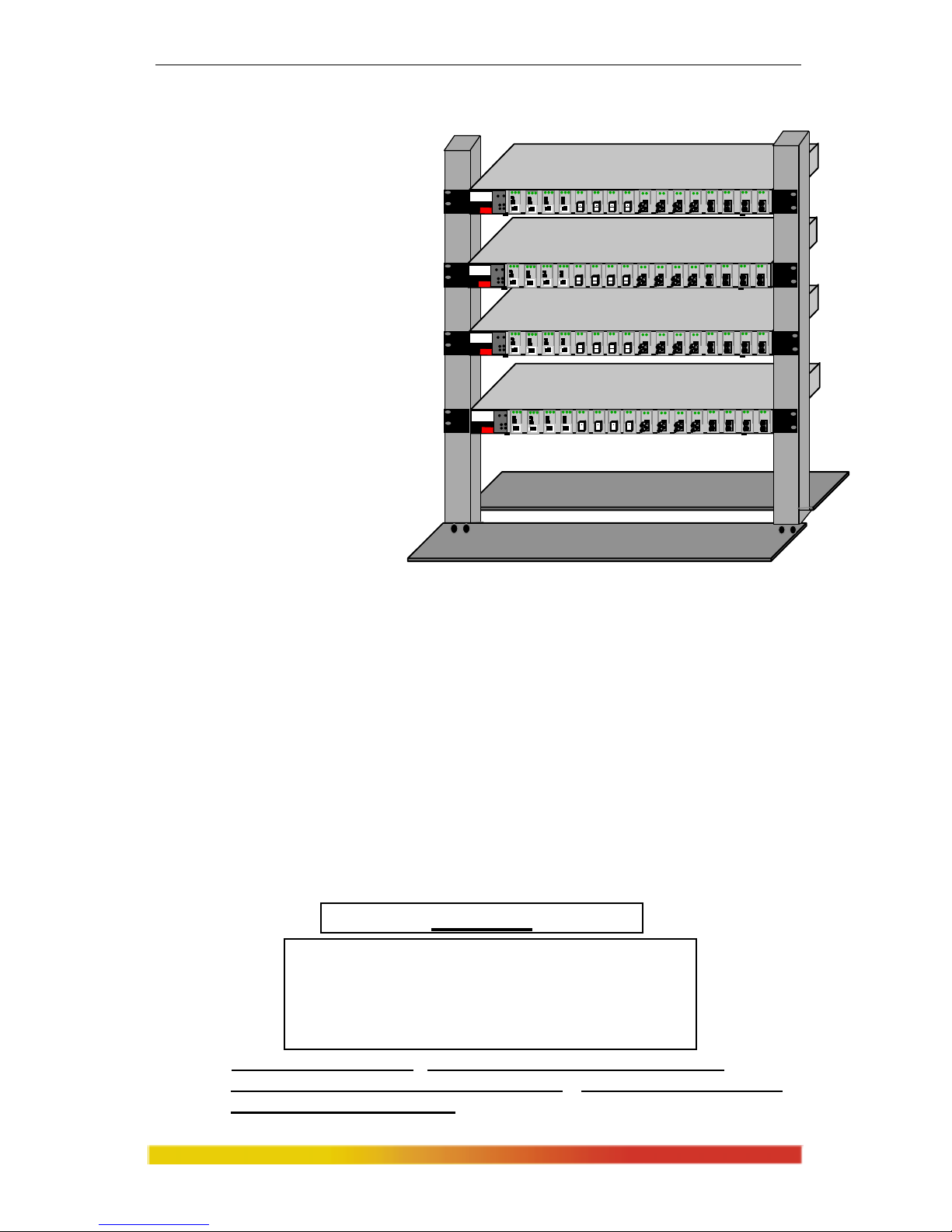
Magnum 8000X Mixed-Media Fiber Hubs Installation and User Guide (05/ 02)
28
www GarrettCom com
..
The 23” brackets and ETSI brackets are also available (optional) for Rackmounting of Magnum 8000X Hubs. The 23” brackets are more popular in Telco
industry where they are
standard for Central Office
rack-mounting purposes. The
23” brackets are mainly used
for larger equipment
assemblies in rack-mounting
frames, and are frequently
accessed in operation from both
sides.
The ETSI (European
Telephone standard) brackets
are similar to the 19” brackets
but use metric dimensions.
The optional 23” brackets and
the ETSI brackets come as a
pair in a package, along with
the necessary screws for
attaching the brackets to the sides of the Magnum Switch unit.
Fig 3.8 Multiple Magnum 8000X
units rack-mounted in a 23”
frame
3.9 Port Module (PM) Installation
The Magnum 8000X is normally received from the factory with all required
PM modules installed. There may
be situations where PM cards need to be added or
replaced. In cases where additional PM cards are needed, the face plate for an available
front-mounted slot must be removed. The following procedure describes this operation.
3.9.1 Preparation for Installing and Removing PMs
Caution- Avoid Static Discharge: The port modules (like most electronic
equipment) are sensitive to static discharge. Use proper ESD measures
when handling port modules.
STOP!!!
Be sure the power cord is unplugged
from the chassis before attempting to remove
and/or replace any PM cards.
Failure to do so may result in damage to the unit
and will void the warranty.
10 100
PWR
BRD
ACT
COL
Magnum 8000X
Mixed Media Hub
GARRETT
1
R L SR L S
R L S
R L S R L
R L
R LR LR L R L
R LR LR L
R LR L R L
10 100
PWR
BRD
ACT
COL
Magnum 8000X
Mixed Media Hub
GARRETT
1
R L SR L S
R L S
R L S R L
R L
R LR LR L R L
R LR LR L
R LR L R L
10 100
PWR
BRD
ACT
COL
Magnum 8000X
Mixed Media Hub
GARRETT
1
R L SR L S
R L S
R L S R L
R L
R LR LR L R L
R LR LR L
R LR L R L
10 100
PWR
BRD
ACT
COL
Magnum 8000X
Mixed Media Hub
GARRETT
1
R L SR L S
R L S
R L S R L
R L
R LR LR L R L
R LR LR L
R LR L R L
Page 36
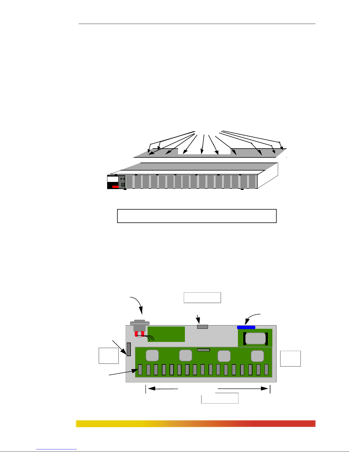
Magnum 8000X Mixed-Media Fiber Hubs Installation and User Guide (05/ 02)
29
www GarrettCom com
..
Step 1. Remove Chassis Cover
To make the installation of port module easy, the top cover is made in two
parts called “front-top” and “rear-top”. There are 6 screws located on front-
top of the unit and two screws each on the left and right edges. Remove these
screws. Once these are removed, the front-top cover is easily lifted off the
chassis base.
When the front-top cover has been removed, the front-interior is exposed.
Figure 3.9.1a: Removing Chassis Cover
Caution: Be careful not to disturb the power supply.
Looking down into the Magnum 8000X unit, notice that there are individual
PM connector sockets for each PM card position. There are 16 PM slots located on the
front of the unit and a bonus slot for an SPM in the rear of the unit. A total of seventeen
slots for seventeen Ethernet segment connections are available. The extreme left
header-position in front is used by the LED Status module. (See Figure 3.9.1b).
Figure 3.9.1b: Magnum 8000X, Top View with Chassis Cover
10100
PWR
BRD
ACT
COL
Magnum 8000X
Mixed Media Hub
GARRETT
1
Front-topChassis Cover
10 Phillips Head
Screws on Front-top
Front of Unit
Inter-Repeater Bus
Power Input
Sixteen PM Slots
Back of Unit
Right
Side
Left
Side
SPM Bonus Slot
Cooling Fan
Power Supply Board
Bridge
LED Status Slot
Page 37

Magnum 8000X Mixed-Media Fiber Hubs Installation and User Guide (05/ 02)
30
www GarrettCom com
..
Step 2. Remove bottom-front Retaining Screws in any PM or Face Plates
On the bottom-front of the unit, there is one retaining screw for each PM card slot.
These screws are used to secure a PM face plate in position. These screws are also used
to secure the individual PM cards, which can be subjected to significant forces from the
attached cables. (See Figure 3.9.1c)
Figure 3.9.1c: Front View - PM Retaining Screws hold Face Plates
PM card installation is covered in Section 3.9.2. PM card removal is covered in
S
ect.3.9.3.
3.9.2 Installing PM Cards in the Magnum 8000X
Up to sixteen front-mounted PM cards may be installed in one Magnum
8000X Fiber Hub unit. Follow these steps to install a PM.
Step 1. Remove front-top chassis cover. See procedure in Section 3.9.1 above.
Step 2. The figure here
illustrates the basic
lay
out of an
individual PM card.
Each PM card fits
into the selected PM
connector socket
slot. Align the
BOTTOM-Front PM
Retaining Screws
10100
PWR
BRD
ACT
COL
Magnum 8000X
Mixed Media Hub
GARRETT
1
Bottom PM Retaining
Screw Hole
Ten(10) Pin
PM Connector
(inserts into main board
)
Printed Circuit card
FRONT
TOP
LED
Page 38

Magnum 8000X Mixed-Media Fiber Hubs Installation and User Guide (05/ 02)
31
www GarrettCom com
..
connector pins on the bottom of the PM card with the connector socket inside
the unit. The pins are slightly angled to facilitate the installation. (Do NOT
straighten the pins before insertion !!)
Step 3. Be sure the pins are precisely aligned with the holes in the header, and the
PM front panel is guided into the front slot cut-out. Then, slowly and
carefully apply enough pressure to insert the PM card’s pins into position,
see Figure 3.9.2b. (If you force the PM down when the pins are not properly
aligned with the holes in the header, the pins will become bent and the PM is
damaged).
Once inserted, the PM card will be secured by the header connector,
the front panel port slot cut-out, and retaining screws.
NOTE: If a PM is difficult to install, try it in another port slot. Some of the
port modules may fit easily in one port slot and be very hard to install in
another.
Figure 3.9.2b: Inserting PM Cards into a Magnum 8000X
NOTE: All PM slots need not be filled in order for the Magnum 8000X unit
to be operational. When leaving PM slots empty, always use a face plate
(M
agnum PM-FP) to cover the slot opening in the front panel. This will
maintain proper cooling air flow, safety, and operation as required by
FCC, CE, and other regulations.
Step 4. Once all P
M cards have been installed (including face plates for empty slots),
the chassis cover should be replaced.
3.9.3 Removing PM Cards
To properly remove a PM card from the Fiber Hub, follow the 3 steps below.
Step 1. Remove chassis cover See procedure in Section 3.9.1 above.
Caution: Be sure the power cord is unplugged.
Step 2. Remove bottom-front retaining screws for the PM and Face Plate
10100
PWR
BRD
ACT
COL
Magnum 8000X
Mixed Media Hub
GARRETT
1
PM CARDS
Page 39

Magnum 8000X Mixed-Media Fiber Hubs Installation and User Guide (05/ 02)
32
www GarrettCom com
..
On the bottom-front of the unit there is one retaining screws for each PM card
and face plate slot. These screws are used to secure a PM card in position (see
Figure 3.9.3a). Remove the front screws of the PM to be removed.
Figure 3.9.3a: Front View - Face Plate & PM Retaining Screws
Step 3. Remove PM Card
Gently pull the PM card up and out of the connector socket (see Figure
3.9.3b).
Figure 3.9.3b: Removing a PM Card
If the slot from which the PM card has been removed is to remain unused, be
s
ure to install a PM face plate cover in it. If another PM card is replacing the
one that has been removed, follow the steps as described for installing an PM
card discussed in Section 3.9.1.
3.10 Preparation for Installing and Removing SPMs
Step 1. Remove Chassis Top Cover
Caution: Be sure the power cord is unplugged.
The 8000X chassis is connected with 20 screws on the top cover. There are
several screws located on top front and back of the unit, and four screws each
on the top left and right sides. Remove these 20 screws from the top edges.
Once these are removed, the top cover is easily lifted off the chassis base.
BOTTOM-Front PM
Retaining Screws
10100
PWR
BRD
ACT
COL
Magnum 8000X
Mixed Media Hub
GARRETT
1
10100
PWR
BRD
ACT
COL
Magnum 8000X
Mixed Media Hub
GARRETT
1
PM CARDS
Page 40

Magnum 8000X Mixed-Media Fiber Hubs Installation and User Guide (05/ 02)
33
www GarrettCom com
..
When the
chassis top cover
has been removed,
the interior of the
unit is exposed.
Figure 3.10a: Removing Chassis Cover
Caution: Be sure the power cord is unplugged.
Caution: Be careful not to disturb the power supply.
Looking down into the Magnum 8000X unit, notice that there is one SPM
connector header located on the rear part of the main board. (See Figure 3.10b).
Figure 3.10b: Magnum 8000X, Top View with Chassis Cover Off
Step 2. Remove Retaining Screws in Face Plates of SPM Bonus Port
On the rear side of the unit there are two retaining screws for Bonus Port slot.
These screws are used to secure an SPM face plate in position. These screws are also
used to secure the SPM modules, which can be subjected to significant forces from the
attached cables. (See Figure 3.10c)
Figure 3.10c: Rear View - SPM Retaining Screws in Face Plates
10100
PWR
BRD
ACT
COL
Magnum 8000X
Mixed Media Hub
GARRETT
1
TopChassis Cover
20 Phillips Head
Screws on Top
Front of Unit
Media Connector
with electronic elements
Inter-Repeater Bus
AC Power Input
Sixteen PM Slots
Back of Unit
Right
Side
Left
Side
SPM Bonus Slot
Cooling Fan
Power Supply Board
Bridge
Inter-Repeater Bus (IRB)
P3 - Interface to unit above.
P4 - Interface to unit below.
AC Power
Connector
Bonus Port Slot,
1 8
OUT
IN
ON
OFF
Screw Holding the SPM face plate
Page 41
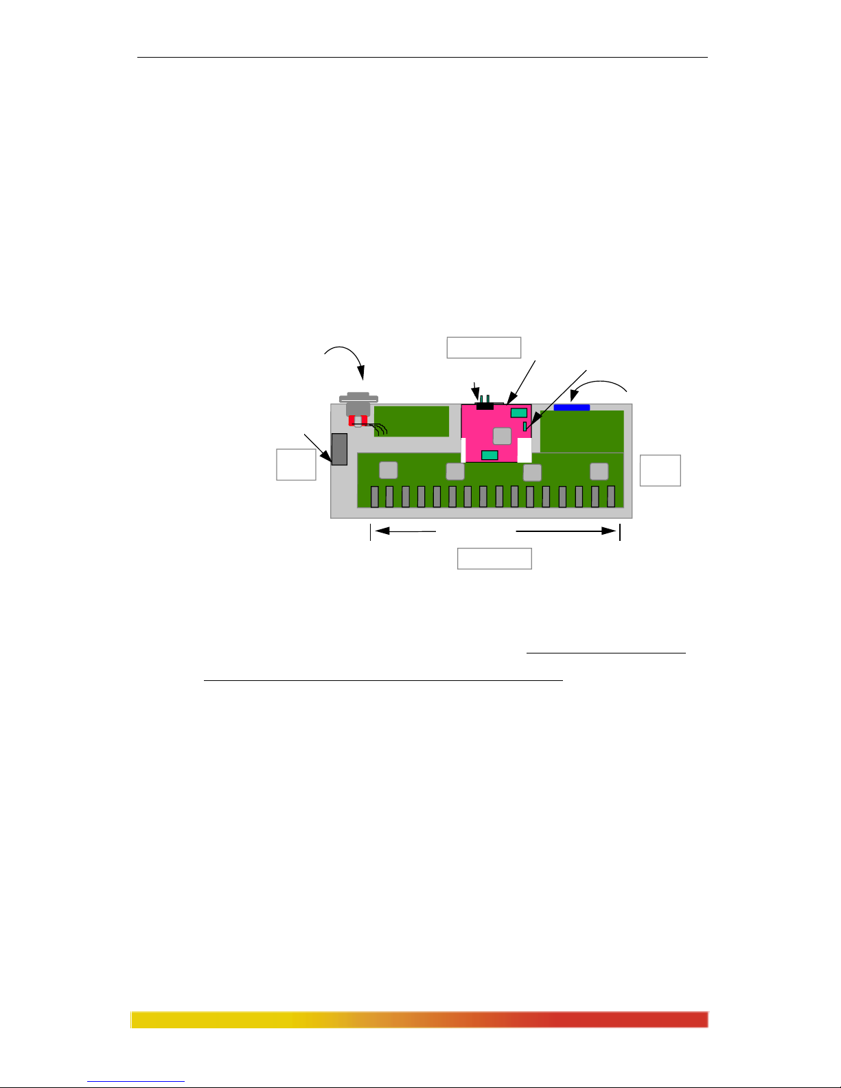
Magnum 8000X Mixed-Media Fiber Hubs Installation and User Guide (05/ 02)
34
www GarrettCom com
..
SPM card installation is covered in Section 3.10.1, PM card removal in Sect3.10.2.
3.10.1 Installing an SPM Module in the Magnum 8000X
There is only one SPM module may be installed in the Magnum 8000X Fiber
Hub unit. The SPM bonus port slot is accessible on the rear of the unit
Follow these steps to install an SPM.
Step 1. Remove top chassis cover. See procedure in Section 3.10a above.
Step 2. The figure 3.10.1a below illustrates the lay
out of an SPM module installed in
a 8000X unit. The SPM module fits easily into the SPM header.
Fig. 3.10.1a Top View : SPM Module Installed in a 8000X
Align the 40-pin male header on the main board of the Magnum 8000X with
the female sockets on the SPM module carefully. Any misalignment of the
pins will prevent proper functioning of the SPM module.
Step 3. Slowly and firmly push the SPM into position. Once inserted, the SPM card
is then secured by the header connector. Re-insert the retaining screws on the
SPM module cover plate to provide stability .
NOTE: The SPM Bonus Port slot need not be populated in order for the
Magnum 8000X unit to be operational. When leaving SPM slots empty, always
use a face plate (supplied and factory-installed in all non-SPM units)) to cover
the slot opening in the rear panel. This will maintain proper cooling air flow for
safety, and operation as required by FCC, CE, and other regulations.
Step 4. Once S
PM card has been installed, the user can adjust the jumper settings
either to half or full duplex. The SPM module, by default, comes with half-
duplex settings. Finally the chassis cover should be replaced and screwed
down.
Inter-Repeater Bus
AC Power Input
Sixteen PM Slots
Back of Unit
Front of Unit
Right
Side
Left
Side
SPM Bonus Slot
Cooling Fan
Power Supp ly Board
SPM Module installed
Jumper Settings For Half/Full duplex
Page 42

Magnum 8000X Mixed-Media Fiber Hubs Installation and User Guide (05/ 02)
35
www GarrettCom com
..
Note: Do not use any other screws(except provided from the factor on the fan side.
Non-standard screws may stop the fan from working, and the heat build-up may
cause serious hazard to the unit.
3.10.2 Removing an SPM Bonus Port Module
To properly remove an SPM module from the Magnum 8000X Stackable
Concentrator follow the three steps below.
Step 1. Remove chassis cover
See procedure in Section 3.10 above.
Caution: Be sure the power cord is unplugged.
Step 2. Remove retaining screws for the SPM, face-plate only
On the rear side of the hub there are two retaining screws for the Bonus Port
slot. These are used to secure an SPM m
odule in position. Remove them.
Step 3. Remove SPM Card
Keep the face-plate screws available. Gently pull the SPM card up and out of
the connector header . If the bonus port from which the SPM card has been
rem
oved is to remain unused, be sure to install an SPM face plate cover in it.
If another SPM card is replacing the one that has been removed, follow the
steps as described for installing an SPM card discussed in Section 3.10 on the
preceding pages.
3.11 Powering the Magnum 8000X
The Magnum 8000X incorporates an internal universal power supply, and has
a male IEC connector for the AC power cord at the right-rear. A six foot 115vac power
MAIN BOARD
SPM
MODULE
POWER
SUPPL Y
STAC KING
CONNECTORS
Retaining
Screws
Fan
Page 43

Magnum 8000X Mixed-Media Fiber Hubs Installation and User Guide (05/ 02)
36
www GarrettCom com
..
cord is supplied with each unit. (Units shipped from the GCI factory to outside the
United States and Canada will not include a 115 vac power cord.)
The Magnum 8000X supports installation environments where the AC
voltage ranges from 90 - 260 volts with a power input frequency of between 47 - 63 Hz
and will consume no more than a maximum of 30 watts. The power connector is located
on the back of the unit. In order to power down the unit, simply unplug the unit’s power
cable In a stacked configuration, this will NOT affect the operation of other units in the
stack. When connecting various Ethernet media, there is no need to power down the
8000X unit. Individual segments of any media type can be connected or disconnected
from PMs without concern for AC power -related problems or damage to the unit.
Page 44

Magnum 8000X Mixed-Media Fiber Hubs Installation and User Guide (05/ 02)
37
www GarrettCom com
..
4.0 Operation
The operation of the Magnum 8000X is described in this section.
4.1 Repeater Functionality
The Magnum 8000X operates as a Mixed-Media Ethernet Hub to support
m
ultiple port segments within two (10 and 100Mbps) collision domains. The
following describes the basic functionality of the Magnum 8000X Fiber Hub.
1. Repeater Functions: Each front port operates in conjunction with the
controller functions of the 8000X chassis as a fully
compliant Ethernet repeater.
The entire hub (or a stack of multiple units) counts as one Dual-Speed repeater.
2. Collisions: W
hen a collision is detected at a port other than the original
receiving port, it generates a jam pattern to the other ports in that domain.
When a collision signal is detected at a receiving port, it generates a jam pattern
to the other ports. The sequence of jam signals depends on the sequence and
location of collisions.
3. Partitioning and Re-connection: An Magnum
8000X will automatically
disconnect (partition) any segment (port) when 64 consecutive collisions occur
or after 6.5 ms of continuous transmissions. Network integrity is checked every
800 ms and segment (port) reconnection occurs after a 512-bit packet is
transmitted without error.
4. Link Status: The Magnum 8000X PMs indicate link integrity for fiber
optic and twisted pair segments. LINK is normally lit. Broken cables or a
loss of power at any point in such segments will turn off the LINK LED.
4.2 Dual-Speed Functionality
The Magnum 8000X handles the two different traffic domains separately
. The
8000X provides switched (bridged) connectivity between the Ethernet (10 Mbps) and
Fast Ethernet (100Mbps) domains. It joins the two network domains for unified
operation, and filters/ forwards packets in both directions to maximize bandwidth
utilization and performance. Magnum 8000Xs are hardware plug-and-play devices.
There is no software set-up to be done at installation or for maintenance. The functions
of the Magnum 8000X are described in this manual.
Each time a packet is received on one domain of the bridge module, the decision is
taken to either to filter or forward the packet. Errored packets are alway
s filtered. For
good packets, the filter and forward decisions are made based on the destination address
contained in each packet. If the destination address is on the same domain from which
the packet originated, then it is filtered and not forwarded to the other domain. If the
destination address is not found to be a match in the address table for the originating
domain, then it is forwarded to the other domain. If it is a new node address coming in
which the switch did not previously know about, it “learns” the new address and puts it
in the correct port address table. See “Address Learning” for more details. This
diagram below shows the filter / forward logic for both domains.
Page 45
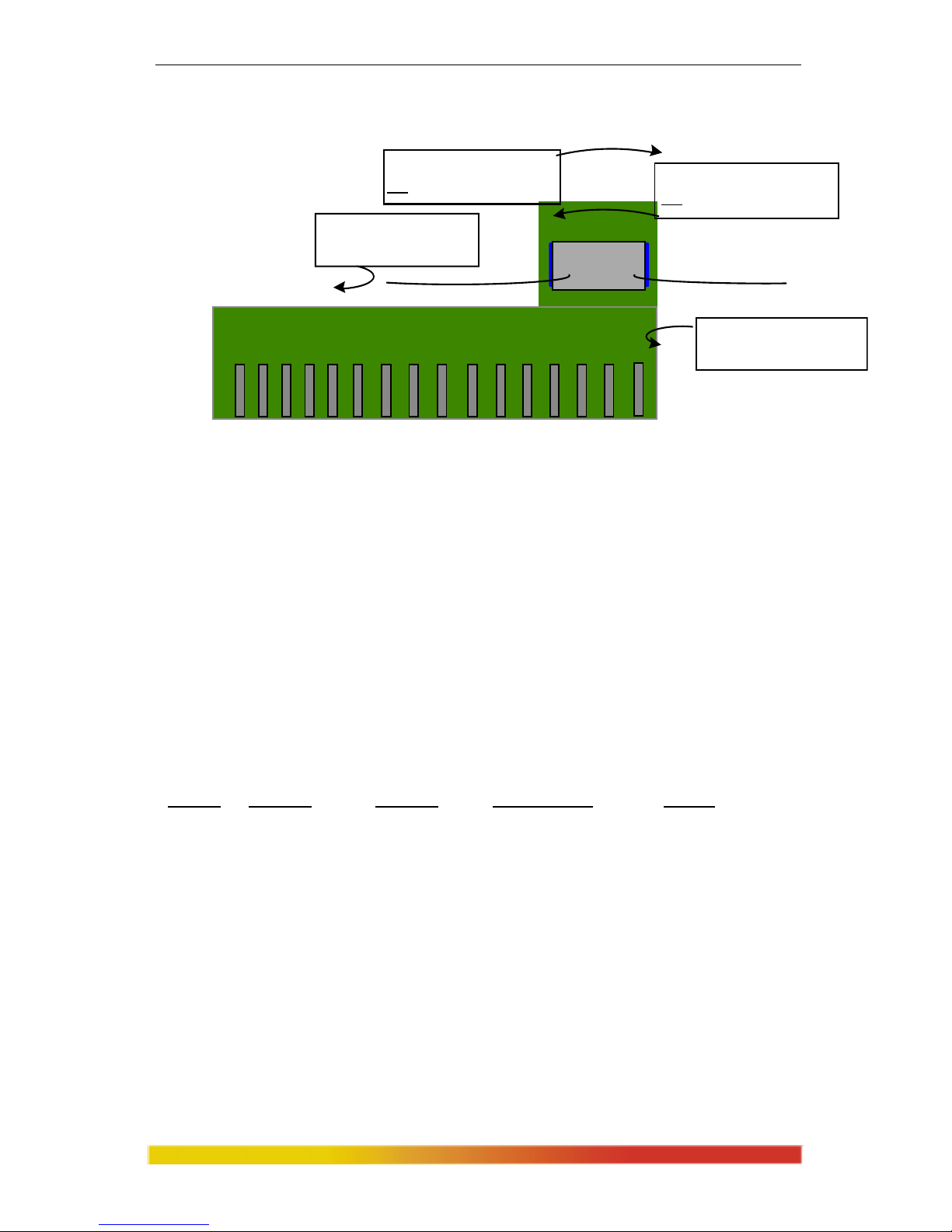
Magnum 8000X Mixed-Media Fiber Hubs Installation and User Guide (05/ 02)
38
www GarrettCom com
..
1. Address Learning (Address Table Maintenance)
The Magnum 8000X bridge module is a state machine design which has a total
address table capacity of 8K addresses. With a large address table, a Magnum 8000X
can serve the needs of a medium-sized to large network. Table 4.2 shows what filter /
forward action the Magnum 8000X will take in each packet-processing situation, and
when a new node address will be added to the internal Address Table. When a new
node-address packet comes into a port for the first time, then the new source address is
“learned” at the same time that the packet is forwarded. After learning, subsequent
packets from the same node address are routinely processed. The address tables are
flushed periodically to update the network status and to purge any inactive stations from
the tables of both domains.
Figure 4.2 : Filtering vs. Forwarding in Dual Speed 8000X
Packet Source Destination Address Table Filter/Forward
Source Address Address Maintenance Action
10 Mbps Not in table Not in table Add source to table Forward
10 Mbps Not in table In table Add source to table Filter
10 Mbps In table Not in table None Forward
10 Mbps In table In table None Filter
100Mbps Not in table Not in table Add source to table Forward
100Mbps Not in table In table Add source to table Filter
100Mbps In table Not in table None Forward
100Mbps In table In table None Filter
Table 4.2: 8000X Dual-Speed Hub Functionality
2. Throughput Increase
By selectively forwarding packets from each domain to the other domain
based on its switching (bridging) logic, the Magnum 8000X increases the available
bandwidth for the users on both sides of the network. As shown in Figure 4.2, it keeps
the local traffic on each side contained, preventing unnecessary
packets and bad packets
from traveling to the other domain and using up bandwidth needlessly over there. This
Bridge Module
100 Mb Traffic
100Mb Domain : 100Mb packets are
filter ed when the destination address is
in the 100Mb domain address table.
100Mb Domain : 100Mb packets are
forwarded when the destination address is
NOT
in the 100Mb domain address tabl e.
10 Mb Domain 100 Mb Domain
10Mb Domain : 10Mb packets are
forwarded when the destination addresse is
NOT
in the 10Mb domain address table.
10Mb Domain : 10Mb packets are
filt ered when the destination address is
in the 10Mb domain address tabl e.
10 Mb Traffic
10 BUS 100
1
0
B
U
S
1
0
0
Page 46

Magnum 8000X Mixed-Media Fiber Hubs Installation and User Guide (05/ 02)
39
www GarrettCom com
..
results in more available network bandwidth on both sides and a throughput increase on
for all users on both domains.
3. Software Transparency
The Magnum 8000X Dual-Speed Hubs need no software set-up and are transparent
to sy
stem and application software, including network management software.
4.3 Auto-negotiation and speed-sensing
The PM-RJ45 and PM-RJ45U ports independently
support auto-negotiation
for shared 10BASE-T and 100BASE-TX modes. When the ‘S’ LED is flashing on a
port, it means that the hub is sending out auto-negotiation pulses on that port. When a
LINK connection is initially made, the other device should respond and both sides
should agree on the speed capability being signaled. The device connected, depending
on what it is, will either signal that it is capable of 10 Mbps or 100Mbps speeds.
Silence means the port defaults to 10 Mbps.
When the ‘S’ LED is steady
ON, the port has auto-negotiated for 100Mbps
operation and is running at 100Mbps. When it is steady OFF, it is at 10 Mbps. If a
8000X copper port is connected to a non-negotiating device, it will default to 10 Mbps
speed. Since Magnum 8000Xs are hubs, front ports always operate in half-duplex
mode.
General information -
Auto-negotiation per-port for dual-speed hubs occurs when:
the devices at both ends of the cable are capable of operation at either 10Mb or
100Mb speed, and can send/receive auto-negotiation pulses, and . . .
-- when the second of the two connected devices is powered up*, i.e., when LINK
is established for a port, or
-- when LINK is re-established on a port after being lost temporarily.
NOTE
– some NIC cards only auto-negotiate when the computer system that they are
in is powered up. These are exceptions to the “negotiate at LINK – enabled” rule, but
may be occasionally encountered
.
4.4 Chassis LEDs
The Magnum 8000X is equipped with six LEDs located on the front of the
chassis unit (see Figure 2.3b). These LEDs are Power (PWR), Bridge(BRD), Collision
(COL) and Activity (ACT) for 10 and 100Mbps speed. They are used to provide visual
indication about the operational condition and traffic activity of the 8000X unit and its
associated PM cards.
Magnum 8000X chassis unit LEDs
LED Description
PWR Illuminates GREEN to indicate that the unit is receiving power.
BR GREEN, Steady ON, unit has bridge inside
COL Flashes YELLOW to indicate a collision, one each for 10 and 100Mbps
ACT Flashes for packet activity, one each for 10 and 100Mbps domains
Page 47

Magnum 8000X Mixed-Media Fiber Hubs Installation and User Guide (05/ 02)
40
www GarrettCom com
..
4.5 Power Budget Calculations for 8000X FPM’s and Fiber Media
Receiver Sensitivity and Transmitter Power are the parameters necessary to
compute the power budget. To calculate the power budget of different fiber media
installations using Magnum products, the following equations should be used:
OPB (Optical Power Budget) = P
T
(min) - PR(min)
where P
T
= Transmitter Output Power, and PR = Receiver Sensitivity
Worst case OPB = OPB - 1dB(for LED aging) - 1dB(for insertion loss)
Worst case distance = {Worst case OPB, in dB} / [Cable Loss, in dB/Km]
where the “Cable Loss” for 62.5/125 and 50/125
µm (M.m) is 2.8 dB/km,
and the “Cable Loss” for 100/140 (Multi-mode) is 3.3 dB/km,
and the “Cable Loss” for 9/125 (Single-mode) is 0.5 dB/km
The following data has been collected from component manufacturer’s (HP’s and
Siemens’) web sites and catalogs to provide guidance to network designers and
installers.
Fiber
Port
Module
Speed,
Std.
Mode
Std.
km
fdx
(hdx)
Wave
-
length
nm
Cable
Size
µm
X’mitr
Output
P
T
,
dB
R’cvr
Sens.
P
R
,
dB
Worst
OPB,
dB
Worst*
distance
Km, fdx
typical
OPB,
dB
typical*
distance
Km, fdx
FPM10-
MST, MSC
10 Mb
FL
Multi-
mode
2
(2)
850
62.5/125
100/140
50/125
-15.0
-9.5
-19.5
-31
-31
-31
14
19.5
9.5
5
5.9
3.4
17
23.5
13.5
6
7
4.8
FPM10-
SST, SSC
10 Mb
FL
Single-
m
ode
10
(5)
1300 9/125 -30 -39 7 14 13 26
FPM-
MST, MSC
100Mb
FX
Multi-
m
ode
2
(0.4)
1300
62.5/125
50/125
-20
-23.5
-31
-31
9.0
5.5
2.5
2.0
14
12
5
4
FPM-SSC
100Mb
FX
Single-
m
ode
18+
(0.4)
1300 9/125 -15 -31 14 28 17.5 35
FPM-MTRJ
100Mb
FX
Multi-
m
ode
2
(0.4)
1300
62.5/125
50/125
-20
-23.5
-31
-31
9.0
5.5
3.0
2.0
15.8
12.2
5.5
4.0
FPM-MV45
100Mb
FX
Multi-
m
ode
2
(0.4)
1300 62.5/125 -14 -31 15 5 16 5.7
FPM-SX
MST, MSC
10/100
Mb SX
Multi-
mode
0.3
(0.3)
850 62.5/125 -12 -15 1 0.3 1.5 0.5
SPM-FDST
SPM-FDSC
100Mb
FX
Multi-
m
ode
2
(n.a.)
1300
62.5/125
50/125
-20
-23.5
-31
-31
9.0
5.5
2.5
2.0
14
12
5
4
* Note: The use of either multi-mode or single-mode fiber to operate at 100Mbps speed
over long distances (i.e., over approx. 400 meters) can be achieved only if the
following factors are both applied:
• The 100Mb fiber segment must operate in full-duplex (FDX) mode, i.e. an
SPM (or equal external unit such as 300ES-FDX) must be used, and
• The worst-case OPB of the fiber link must be greater than the fiber cable’s
passive Attenuation.
(Attenuation = Cable loss + LED aging loss + Insertion loss + safety factor)
Page 48

Magnum 8000X Mixed-Media Fiber Hubs Installation and User Guide (05/ 02)
41
www GarrettCom com
..
5.0 Introduction - Magnum 8000X Port Modules
This chapter describes each Port Module (PM), including appearance,
functionality, and status displays.
5.1 Inspecting the Package and Product
This section applies only to PMs shipped as separate items, i.e., PMs not
factory
installed in a Magnum 8000X PM slot or in bonus port slot.
Examine the shipping container for obvious damage prior to installing a PM;
notify
the carrier of any damage which you believe occurred during shipment
or delivery. Inspect the contents of this package for any signs of damage and
ensure that the items listed below are included.
This package should contain:
One or more PMs.
Remove the PM(s) from the shipping container. Be sure to keep the shipping
container should you need to ship any of the PMs separately at a later date.
In the event there are items missing or damaged contact your supplier. If you
need to return the unit, use the original shipping container if possible. Refer to
Chapter 5 for specific return procedures.
5.2 Product Description
An important feature of the Magnum 8000X Hub is the use of individual Port
Modules (PMs) for flexible mixed-media connectivity to RJ-45 and fiber
media. Since the Magnum 8000X’s have dual-speed capability per-port, the
front port slots are designed to support all standard Ethernet media types at 10
or 100Mps speed. Each PM provides one port for connecting one Ethernet
segment with its individual connector type and media.
For a list and brief illustration of Port Module ty
pes, refer to Section 2.4
Each PM is individually described in the following sections.
Page 49

Magnum 8000X Mixed-Media Fiber Hubs Installation and User Guide (05/ 02)
42
www GarrettCom com
..
5.2.1 FPM-MST, 100Mbps multi-mode FX-ST-type, “twist-lock” connector
The Magnum FPM-MST is a
multi-mode 100Mbps fiber optic module
equipped with a dual ST-type connector. It
functions as a fiber optics transceiver to
support 100BASE-FX network segments.
When installed in an 8000X half-duplex
hub, it supports fiber optic cable distances
only up the IEEE-specified 100Mbps
shared-collision-domain distance limits,
i.e., typically 200 meters.
The module is equipped with an Activity (A) LED, and a Link (L) LED
which indicates proper connectivity with the remote device when lit. Lettering on the
front of the module identifies it as “100 FX” to avoid confusion with other similar-
looking FPMs.
5.2.1a FPM10-MST, 10 Mbps multi-mode FL-ST-type, “twist-lock” connector
The Magnum FPM10-MST is a multi-mode 10 Mbps fiber optic module
equipped with a dual ST-type connector. It looks similar to the 100Mb FPM-MST, but
has the lettering “10 Mb” on the front to distinguish it.
5.2.2 FPM-MSC 100Mbps multi-mode FX
-SC-type, “snap-in” connector
The Magnum FPM-MSC is also
a multi-mode 100Mbps fiber optic
transceiver module, similar to the FPM-
MST. It has the same LEDs indicating port
activity (A), and Link (L) operational, and
the same face-plate lettering.
While the functionality of the
these two modules is the same, the FPM-
MSC is equipped with an SC-ty
pe "snap-
in" connector instead of an ST-type.
1
ACTIVITY
LINK
2
100BASE-FX, -SX and 10BASE-FL
ST Connectors
1
2
A L
1
ACTIVITY
LINK
2
100BASE-FX, -SX and 10BASE-FL
SC Connectors
1
2
A L
Page 50

Magnum 8000X Mixed-Media Fiber Hubs Installation and User Guide (05/ 02)
43
www GarrettCom com
..
5.2.2a FPM10-MSC, 10 Mbps multi-mode FL-SC-type, “snap-in” connector
The Magnum FPM10-MSC is a multi-mode 10 Mbps fiber optic module
equipped with a dual SC-type connector. It looks the same as the 100Mb FPM-MSC,
but has lettering “10 Mb” on the front to distinguish it.
5.2.3 FPM-SSC 100Mbps single-mode FX
-SC-type, “snap-in” connector
The Magnum FPM-SSC is a single-mode 100Mbps fiber optic module
equipped with a dual SC-type connector. It functions as a full fiber optic transceiver to
support single-mode fiber
networks.
The FPM-SSC, when
installed in a Magnum 8000X
hub, supports fiber distances the
same as 100Mbps multi-mode
ports because of the 100Mbps
collision domain limitations, so
it is only practical for use where
single-mode fiber cable is
already installed and must be used.
Note - to support long fiber distance with the Magnum 8000X, use either
10Mbps modules in front ports (which can go up to 2Km), or use a 100Mbps full-
duplex SPM in the bonus port which has no collision dom
ain limits.
The FPM-SSC is equipped with an Activity
(A) LED, and LINK(L) LEDs
identical to those of the FPM-MSC. To distinguish the single-mode FPM-SSC from the
multi-mode FPM-MSC, the label “Sgl. M.” is at the top of the faceplate of the FPM-
SSC.
5.2.3a FPM10-SSC, 10Mbps single-mode FL-SC-type, “snap-in” connector
The Magnum FPM10-SSC is a single-mode 10 Mbps fiber optic module equipped with
a dual SC-type connector. It looks the same as the 100Mbps FPM-SSC, but has
lettering “10 Mbps” on the front to distinguish it.
1
ACTIVITY
LINK
2
100BASE-FX, 10BASEFL sgl.mode
SC Connectors
1
2
A L
Page 51

Magnum 8000X Mixed-Media Fiber Hubs Installation and User Guide (05/ 02)
44
www GarrettCom com
..
5.2.3b FPM10-SST, 10Mbps single-mode FL-ST-type, “twist-lock” connector
The Magnum FPM10-SST is a single-mode 10 Mbps fiber optic module equipped with
a dual ST-type connector. To distinguish the single-mode FPM10-SST from the multi-
mode FPM10-MST, the label “Sgl. M.” is at the top of the faceplate of the FPM10-SST.
5.2.4 FPM-MTRJ, 100Mb multi-mode FX, MTRJ small-form-factor
connector
Magnum FPM-MTRJ is a multi-mode fiber optic module equipped with a
small-form-factor MTRJ-type connector. It looks almost like an RJ-45 port, but it is
black in color. The MT-RJ’s small size and
ease of connection make it a good choice for
100Mbps “fiber-to-the-desktop” Ethernet
connectivity. When installed in an 8000X
half-duplex hub, it supports fiber optic cable
distances only up the 100Mbps shared-
collision-domain distance limits, i.e., typically
200 meters.
The functionality of this 100BASE-
FX multi-mode FPM is same as the ST and
SC-types, and it is equipped with the same
ACTIVITY (A) and LINK (L) LEDs to indicate proper connectivity with the remote
device. It has the same “100Mb FX” lettering on the faceplate. Note that the other end
of the fiber cable may have a different connector, not necessarily an MT-RJ type.
5.2.5 FPM-MV45, 100Mbps multi-mode FX, VF-45 small-form-factor
connector
Magnum FPM-MV45 is a multi-mode fiber
FX “small-form-factor” VF-45 connector used primarily
in 100Mbps fiber-to-the-desktop links. Its size is
similar to the MT-RJ port, but the VF-45 shell is
slightly larger. When not in use, its appearance is
distinctive because it has a tiny hinged door over the
port hole to act as a dust cover.
A L
1
2
100BASE-FX MT-RJ
Connector
1
ACTIVITY
2
LIN
K
“small-form-factor”
1
2
1
ACTIVITY
2
LINK
LINK
100BASE-FX MV-45
Connector
“small-form-
”
A L
Page 52

Magnum 8000X Mixed-Media Fiber Hubs Installation and User Guide (05/ 02)
45
www GarrettCom com
..
When installed in a Magnum 8000X half-duplex hub, it supports fiber optic
cable distances only up the 100Mbps shared-collision-domain distance limits, i.e.,
typically 200 meters.
The small size, about the same as an RJ-45, reduces the size of wiring panels
in wiring closets while providing the advantage of “future-proof” fiber optic
technology.
The cable port is a “plug-in” connector, with both fiber strands terminated in
one housing that cannot be improperly
inserted. The module is equipped with a LINK
(L) LED to indicate proper connectivity with the remote device, and an ACTIVITY (A)
LED that flashes to show when Fast Ethernet packets are being received.
5.2.6 FPM-SXMST and SXMSC (100BASE-SX) when available !!
The FPM-SXMST port module,
better known as “short wavelength Fast
Ethernet,” looks essentially
identical to other
ST and SC connectors. The FPM-SXMST
based on 870 nm wavelength comes in multi-
mode only, and may eventually become a
cheaper solution for Fast Ethernet fiber-to-
the-desktop segments.
FPM-SXMST supports fiber
transmission connectivity
up to 300m distance is suitable for the users requiring higher
bandwidth in their LANs.
However, the connection of fiber
cable to the FPM-SXMST is the same as other
ST-ty
pe “Twist-lock” connectors. The module
is equipped with Activity(A) and Link(L)
LEDs to indicate proper connectivity with the
remote device.
As an additional indicator, a multi-
m
ode SX port emits light (red in color) that is
in the visible spectrum and which can be seen
by looking into the port with the power on
1
100BASE-SX with ST
Connectors
2
1
ACTIVITY
LINK
2
SX “short wavelength”
A L
1
ACTIVITY
LINK
2
100BASE-SX, with
SC Connectors
1
2
A L
Page 53

Magnum 8000X Mixed-Media Fiber Hubs Installation and User Guide (05/ 02)
46
www GarrettCom com
..
and with no cable connected. The FX port emits light outside of the visible spectrum
and will always look dark to the human eye.
5.2.7 PM-RJ45 and RJ45U (Twisted Pair)
The PM-RJ45 card supports Ethernet twisted pair segments of any standard
length. It is equipped with a single RJ-45 connector and an Auto/100 switch. The RJ-45
connector is shielded to minimize emissions and will allow both unshielded twisted pair
(UTP) and shielded twisted pair (STP) cable connections. The Auto/100 switch is
provided for user selection between operation in the auto-negotiation mode (Auto) or
fixed-at-100Mb (100) with no auto-negotiation and no 10 Mbps.
The PM-RJ45U module is equipped with a Media Dependent Interface-
Crossover (MDI-X) push switch to allow for cas
caded connections. This feature
eliminates the need for a special twisted
pair crossover cable.
With the switch in the IN
position, the PM-TP port is used for
cascaded and up-link connections (i.e.: a
connection to another repeater or hub or
concentrator typically.) When used for
segments going to workstations and
other user device connections, the MDI-
X switch should be in the OUT position.
The PM-RJ45 will support 10BASE-T unshielded twisted pair wiring (UTP)
environments with maximum segment distances up to 100m (325 ft.), or shielded
twisted pair wiring (STP) of 150m (500 ft.). This module is designed with internal
transceiver functionality
. The PM-RJ45 has ACTIVITY, LINK and SPEED LEDs.
Important Note: For the PM-RJ45U Crossover Switch -
OUT for workstations and user connections.
IN for Up-Link connections to other hubs, etc.
The RJ-45 pins normally (TP crossover switch DOWN) are per the
standard for hubs-to-users twisted pair wiring: 1 = receive+, 2 = receive-,
3 = transmit+, 6 = transmit-, other pins not used. When the TP crossover
switch is UP, the pins of the RJ-45 port are per the standard for up-links
using twisted pair wiring, i.e., the transmit and the receive pairs are
exchanged: 1 = transmit+, 2 = transmit-, 3 = receive+, 6 = receive-, other
pins not used.
1
ACTIVITY
SPEED
2
3
LIN
K
Shielded RJ-45
Connector
Auto/100 Switch
1
2
3
RJ45U
Cross-Over
Push Switch
PM-RJ45U
1
Page 54

Magnum 8000X Mixed-Media Fiber Hubs Installation and User Guide (05/ 02)
47
www GarrettCom com
..
5.2.8 PM-FP
The PM-FP is a blank face plate
that must be installed in any empty PM slot.
When the Magnum 8000X chassis contains
less than twelve front-mounted PMs, the
empty front slots must be covered with the PM-FP face plate PM-FP
in order to maintain proper cooling air flow, and for safety, etc.
Note:
The PM-FP
must be installed in
each em
pty
PM slot.
Page 55

Magnum 8000X Mixed-Media Fiber Hubs Installation and User Guide (05/ 02)
48
www GarrettCom com
..
6.0 TROUBLESHOOTING
All Magnum Ethernet products are designed to provide reliability and
consistently high performance in all network environments. The installation of
Magnum 8000X Mixed-Media Fiber Hub is a straightforward procedure (see
INSTALLATION, Section 2.6); the operation is also straightforward and is discussed
in Section 4.
Should problems develop during installation or operation, this section is
intended to help locate, identify
and correct these types of problems. Please follow the
suggestions listed below prior to contacting your supplier. However, if you are unsure
of the procedures described in this section or if the Magnum 8000X Mixed-Media Fiber
Hub is not performing as expected, do not attempt to repair the unit; instead contact
your supplier for assistance or contact GarrettCom Customer Support.
6.1 Before Calling for Assistance
1. If difficulty is encountered when installing or operating the unit, refer back to
the Installation Section of the applicable chapter of this
manual. Also check
to make sure that the various components of the network are interoperable.
2. Check the cables and connectors to ensure that they have been properly
connected and the cables/wires have not been crimped or in some way
impaired during installation. (About 90% of network downtime can be
attributed to wiring and connector problems.)
3. Make sure that an AC power cord is properly attached to each Magnum
8000X Mixed-Media Fiber Hub unit. Be certain that each AC power cord is plugged
into a functioning electrical outlet. Use the PWR LEDs to verify each unit is receiving
power.
4. If the problem is isolated to a network device other than the Magnum 8000X
Mixed-Media Fiber Hub product, it is recommended that the problem device is replaced
with a known good device. Verify whether or not the problem is corrected. If not, go
to Step 5 below. If the problem is corrected, the Magnum 8000X Mixed-Media
Fiber Hub and its associated cables are functioning properly.
5. If the problem continues after completing Step 4 above, contact y
our supplier
of the Magnum 8000X Mixed-Media Fiber Hub unit or if unknown, contact
GarrettCom, Inc.by fax, phone or email (support@garrettcom.com) for assistance.
Page 56

Magnum 8000X Mixed-Media Fiber Hubs Installation and User Guide (05/ 02)
49
www GarrettCom com
..
6.2 When Calling for Assistance
Please be prepared to provide the following information.
1. A complete description of the problem, including the following points:
a. The nature and duration of the problem;
b. Situations when the problem occurs;
c. The components involved in the problem;
d. Any particular application that, when used, appears to create the problem;
2. An accurate list of GarrettCom product model(s)involved, with serial
number(s). Include the date(s) that you purchased the products from your
supplier.
3. It is useful to include other network equipment models and related hardware,
including personal computers, workstations, term
inals and printers; plus, the
various network media types being used.
4. A record of changes that have been made to your network configuration prior
to the occurrence of the problem. Any changes to system administration
procedures should all be noted in this record.
6.3 Return Material Authorization (RMA) Procedure
All returns for repair must be accompanied by a Return Material
Authorization (RMA) number. To obtain an RMA number, call GarrettCom
Customer Service at (510) 438-9071 during business hours in California or email to
support@garrettcom.com). When calling, please have the following information
readily available:
Name and phone number of your contact person.
Name of your company / institution
Your shipping address
Product name
Serial Number (or Invoice Number)
Packing List Number (or Sales Order Number)
Date of installation
Failure symptoms, including a full description of the problem.
Page 57

Magnum 8000X Mixed-Media Fiber Hubs Installation and User Guide (05/ 02)
50
www GarrettCom com
..
GarrettCom will carefully test and evaluate all returned products, will
repair products that are under warranty at no charge, and will return the warrantyrepaired units to the sender with shipping charges prepaid (see Warranty
Information, Appendix A, for complete details). However, if the problem or
condition causing the return cannot be duplicated by GarrettCom, the unit will be
returned as:
No Problem Found.
GarrettCom reserves the right to charge for the testing of non-defective
units under warranty. Testing and repair of product that is not under warranty will
result in a customer (user) charge.
6.4 Shipping and Packaging Information
Should you need to ship the unit back to GarrettCom, please follow these
instructions:
1. Package the unit carefully. It is recommended that you use the original
container if available. Units should be wrapped in a "bubble-wrap" plastic
sheet or bag for shipping protection. ( You may retain all connectors and
this Installation Guide.)
CAUTION: Do not pack the unit in Styrofoam "popcorn" type packing
material. This material may cause electro-static shock damage to the unit.
2. Clearly mark the Return Material Authorization (RMA) number on the
outside of the shipping container.
3. GarrettCom is not responsible for y
our return shipping charges.
4. S
hip the package to:
GarrettCom, Inc.
47823 Westinghouse Drive
Fremont, CA 94539
Attn.: Customer Service
APPENDIX A: WARRANTY INFORMATION
GarrettCom, Inc. warrants its products to be free from defects in
materials and workmanship for a period of three (3) years from the date of
shipment by GarrettCom.
During this warranty period, GarrettCom will repair or, at its option,
replace components in the products that prove to be defective at no charge other
than shipping and handling, provided that the product is returned pre-paid to
GarrettCom.
This warranty
will not be effective if, in the opinion of GarrettCom, the
product has been damaged by misuse, misapplication, or as a result of service or
modification other than by
GarrettCom.
GarrettCom reserves the right to make a charge for handling and
inspecting any product returned for warra
nty repair which turns out not to be
faulty.
Please complete the warranty card as this acts as a product registration,
and ma
il it to GarrettCom within two weeks of your purchase.
Page 58
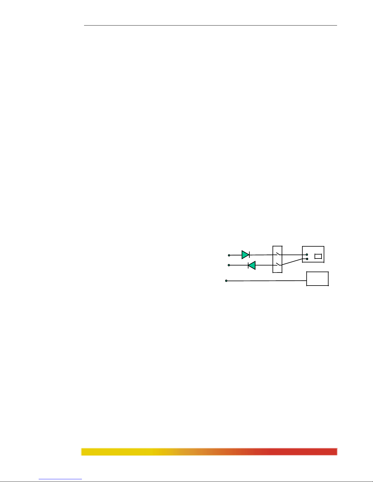
Magnum 8000X Mixed-Media Fiber Hubs Installation and User Guide (05/ 02)
51
www GarrettCom com
..
APPENDIX B : Internal DC Power Supply Option
B1.0 SPECIFICATIONS - FOR MAGNUM MIXED -MEDIA 8000X HUBS
Power Supply (Internal -48 VDC Option)
DC Power Connector: 3 terminals: “
-“, “GND”, “+”
Input Voltage: 36 - 70 VDC
Power Consumption: Model 8000X: 30 watt typical, 50 watts max.
Power Supply (Internal 24 VDC Option)
DC Power Connector: 3 terminals: “
-“, “GND”, “+”
Input Voltage: 20-36 VDC
Power Consumption: Model 8000X: 30 watt typical, 50 watts max.
Power Supply (Internal 125 VDC Option)
DC Power Connector: 3 terminals: “
-“, “GND”, “+”
Input Voltage: 120 - 160 VDC
Power Consumption: Model 8000X: 30 watt typical, 50 watts max.
With the
exception of the power supply, all specifications and functions of
Magnum 8000X-48VDC models are identical to those listed in the main manual.
B2.0 -48VDC, 24VDC & 125VDC POWER OPTION, THEORY OF OPERATION
The -48VDC, 24VDC & 125VDC power options are designed using diodes
inside on each DC power input line
behind the two external power
connection term
inals, so that the power
from an external source can only flow
into the unit. This allows the 8000X to
operate only whenever DC power is
correctly applied to the two inputs. It protects the 8000X from incorrect DC input
connections. An incorrect polarity connection, for example, will neither affect the
8000X, its internal power supply, nor will it blow the fuse in the internal power supply.
The manual power “On-Off” Switch (optional) is used for powering the unit
on and off when it is
placed into or taken out of service.
B3.0 APPLICATIONS FOR DC POWERED ETHERNET HUBS
Magnum 8000X’s are easily installed in a variety
of applications where 48VDC, 24VDC & 125VDC power is used as the primary power source. The- 48VDC,
24VDC & 125VDC power configuration provides an Ethernet networking solution
utilizing a special power supply in hubs with a proven track record.
The –48VDC solution is particularly useful in the telecom
munication
industry, where it is common for facilities to operate on -48VDC power. Such
companies include regular and wireless telephone service providers, Internet Service
Providers (ISPs) and other communication companies. In addition, many high
A+
A-
GND
GND
CHASSIS
FUSE
+
-
SUPPLY
HUB
POWER SWITCH
Page 59

Magnum 8000X Mixed-Media Fiber Hubs Installation and User Guide (05/ 02)
52
www GarrettCom com
..
availability equipment services, such as broadcasters, publishers, newspaper operations,
brokerage firms and other facilities often use a battery backup system to maintain
operations in the event of a power failure. It is also frequently used for computer system
backup, management and operations monitoring equipment.
The 24VDC & 125VDC solution are particularly useful in the Industrial environment,
where it is common for facilities to operate on 24VDC or 125VDC power. The
125VDC solution is mainly used in power utilities, such as electrical substations,
electrical generating plants, etc. The 24VDC applications are mainly in the Industrial
environment, such as factory floor, HVAC equipment, military equipment, etc.
B4.0 INSTALLATION
This section describes the
installation of the -48 VDC, 24VDC &
125VDC power s
ource leads to the -48
VDC, 24VDC & 125VDC power terminal
block on the Magnum 8000X. (see figure at
the right).
Figure B4.1: -48VDC Terminal Block on Magnum 8000X -48VDC
In this picture, the -48VDC terminal block on the Magnum 8000X is located
on the rear of the unit and is equipped with three (3) screw-down lead posts. It is
similar for 24VDC and 125VDC options on the 8000X. The leads are identified as
negative (-), positive (+), and chassis ground (GND).
The actual connection procedure is very straightforward. Simply connect the
leads to the Magnum
unit, beginning with ground. Ensure that each lead is securely
tightened.
Note: The GND should be hooked up first. The 8000X unit has a floating ground, so
th
e user may elect to Ground either + or = terminal to suit the customer’s use.
Before connecting hot lines to the Terminal Block of –48VDC, 24VDC or
125VDC, always use a digital voltmeter to measure the output voltage of the power
supply and determine the lead which is more “+
ve potential”. The more “+ve”
voltage lead from 48V or –48V supply must be connected to the post labeled “+”.
An ON-OFF manual switch is optional for DC power. This can be used to cut off power
connections, and as a RESET for the Hub.
B4.1 UL Requirements
1. Minimum 14 AWG cable for connection to a Centralized DC power source.
2. Fastening torque of the lugs on the terminal block: 9 inch pound max.
3. Centralized DC Power Source cable securement, use at least four cable ties
to secure the cable to the rack at least 4 inches apart with the first one
located within 6 inches of the terminal block.
36-70VDC
_
+
GND
ON
OFF
Page 60

Magnum 8000X Mixed-Media Fiber Hubs Installation and User Guide (05/ 02)
53
www GarrettCom com
..
B5.0 OPERATION
Operation of the Magnum 8000X with the optional -48VDC, 24VDC &
125VDC power supply is identical to that of the AC-powered models.
B6.0 ORDERING INFORMATION
To order the optional –48VDC power supply factory installed, add a suffix of
“-48VDC” after the product’s standard model # Example: Magnum 8000X
-48VDC.
Similarly, to order the optional 24VDC or 125VDC industrial specific power
supply
factory installed, add a suffix of “–24VDC or “–125VDC” after the product’s
standard model #. Example: Magnum 8000X-24VDC or Magnum 8000X-125VDC.
B7.0 TROUBLESHOOTING P
lease refer to Section 6.0
APPENDIX C: Internal DC Dual-Source Power Option
C1.0 SPECIFICATIONS - FOR 8000X MIXED-MEDIA FIBER HUBS
Power Supply (Internal, -48VDC Dual-Source, model # Dual-Src48V)
DC Power Connector: First Source: “A+”, “A-“, 2nd Source “B-“, “B+”
GND: Terminal for “earth” or ground wire connection to the hub chassis
Input: Two separate sources, each at 36 - 70 VDC
Power Consumption: Model 8000X: 30 watt typical, 50 watts max.
Power Supply (Internal, 24VDC Dual-Source, model # Dual-Src24V)
DC Power Connector: First Source: “A+”, “A
-“, 2nd Source “B-“, “B+”
GND: Terminal for “earth” or ground wire connection to the hub chassis
Input: Two separate sources, each at 20 - 36 VDC
Power Consumption: Model 8000X: 30 watt ty
pical, 50 watts max.
Power Supply (Internal, 125VDC Dual-Source, model # Dual-Src125V)
DC Power Connector: First Source: “A+”, “A-“, 2nd Source “B-“, “B+”
GND: Terminal for “earth” or ground wire connection to the hub chassis
Input: Two separate sources, each at 120 - 160 VDC
Power Consumption: Model 8000X: 30 watt ty
pical, 50 watts max.
With the exception of the dual DC input power connections and the power
supply, all specifications and configuration options for the Magnum 8000X-48VDC,
8000X-24VDC & 8000X-125VDC with this Dual-Source option are identical to those
listed in the Magnum 8000X Fiber Hubs Installation and User Guide, including
Appendix B “Internal DC Power Supply Option”
C2.0 MAGNUM 8000X , with -48VDC, 24VDC & 125VDC Dual-Source option
Page 61

Magnum 8000X Mixed-Media Fiber Hubs Installation and User Guide (05/ 02)
54
www GarrettCom com
..
The hub models with the internal -48VDC, 24VDC &125VDC Dual-Source
power supply are designed for installations where a battery plant is the power source,
and where two separate power sources are utilized in order to increase operational
uptime and to simplify maintenance.
The functionality of the Magnum 8000X-48VDC, 24VDC or 125VDC DualSource Option hubs are identical to the standard AC-powered models. All Port
Module, SNMP and stacking options are available for configuration with Dual-Source
Option units. Refer to the main sections of this Installation and User Guide for a
detailed description of the Magnum 8000X Hubs.
C3.0 DUAL-SOURCE OPTION, THEORY OF OPERATION
The Dual-Source DC power option is designed using diodes inside of the hub
on each DC power input line. A diode is
placed in each of the four input lines
(behind the four external power connection
terminals) so that power from an external
source can only flow into the hub. This
allows the hub to operate whenever DC
power is correctly applied to either or both
of the two inputs.
C4.0 FEATURES AND BENEFITS OF THE DUAL-SOURCE DESIGN
a) The hub can receive power from either input, “A” or “B”. The hub will normally draw its
power from the DC source with the highest voltage at a given time.
b) The hub will not allow power to flow from a higher voltage input to a lower voltage input, i.e.
the two DC power sources are not mixed together by the hub.
c) When one correct DC input is present, the hub will receive power if the other DC input is
absent, or even if it is connected with reverse polarity or shorted or grounded.
d) Reverse polarity connections, if they should accidentally occur on either input, will not
damage the hub or power supply internally (nor will it blow the fuse in the internal power
supply) because of the blocking action of the diodes. This is true even if one input connection
is reversed while the hub is operating from the other source.
e) The hub will not receive power (and will not work) when both inputs are simultaneously
absent or are both incorrectly connected.
C5.0 INSTALLATION
This section describes the proper connection of the -48VDC, 24VDC &
125VDC dual source leads to the -48VDC, 24VDC & 125VDC power terminal block
on the Magnum 8000X hub (shown in Figure C4.0).
The -48VDC terminal block on the Magnum 8000X is located on the right
rear of the unit and is equipped with five (5) screw-down lead posts (see Figure C5.0).
The primary terminals are identified as positive (A+), negative (A-), and the secondary
power terminals as negative (B-), positive (B+). The chassis “earth” or ground (GND),
is a threaded post with a #6 nut. The dual source terminal block for 24VDC and
125VDC are similar.
GND
FUSE
+
-
SUPPLY
A+
A-
B-
B+
GND
CHASSIS
HUB
Page 62

Magnum 8000X Mixed-Media Fiber Hubs Installation and User Guide (05/ 02)
55
www GarrettCom com
..
Figure C5.0: -48V DC Dual-Source, wiring connections to the External
Terminal Block on a Magnum 8000X 48VDC with Dual-Source option
Note: The GND should be hooked up first. The 8000X unit has a floating
ground, so the user may elect to Ground either + or = terminal to suit the customer’s
use.
Before connecting to Terminal Block of –48VDC, 24VDC or 125VDC,
always use a digital voltmeter to measure the output voltage of the power supply and
determine the lead which is more “+
ve potential”. The more “+ve” voltage lead from
48V or –48V supply must be connected to the post labeled “+”.
The connection procedure is straightforward. Simply connect the DC leads to
the hub’s power term
inals, positive (+) and negative (-) screws. The use of Ground
(GND) is optional; it connects to the hub chassis. Ensure that each lead is securely
tightened.
The 24VDC & 125VDC terminal block on Magnum 8000X is similar to that
described in the –48VDC info above.
C5.1 UL Requirements
The following must be adhered to in order to conform to UL requirements:
1. Minimum 14 AWG cable for connection to a Centralized DC power source.
2. Fastening torque of the lugs on the terminal block: 9 inch pound max.
3. Centralized DC Power Source cable securement, use at least four cable ties
to secure the cable to the rack at least 4 inches apart with the first one
located within 6 inches of the terminal block.
C6.0 ORDERING INFORMATION
To order the optional Dual-Source -48VDC power supply factory installed,
order “Dual-Src-48V” as a separate line item following the product model.
Example: Magnum 8000X-48VDC
Dual-Src48V for regular model with no ON-OFF switch
or Dual-Src48V-SWITCH for m
odel with ON-OFF switch
Similarly to order “Dual-Src 24V” or “Dual-Src 125V” as a separate line
item following the product model.
Example: Magnum 8000X
-24VDC or Magnum 8000X-125VDC
Dual-Src48V for regular model with no ON-OFF switch
or Dual-Src48V-SWITCH for m
odel with ON-OFF switch
36-70VDC
GND
A+ A- B- B+
36-70VDC
Page 63

Magnum 8000X Mixed-Media Fiber Hubs Installation and User Guide (05/ 02)
56
www GarrettCom com
..
C7.0 OPERATION
Operation of the Dual-Source Magnum 8000X-48VDC, 24VDC & 125VDC
hub models are identical to that of the standard models. Please refer to the applicable
sections of the “Installation and User Guide” for more information on the basic hubs.
 Loading...