

Page 1

www GarrettCom com
..
Magnum 3000
Stackable Hubs
Installation and User Guide
Page 2

Magnum 3000 Stackable Hubs Installation and User Guide (07/06)
i
www GarrettCom com
..
Magnum 3000
Stackable Hubs
Installation and User Guide
Part #: 84-00060 (Rev. 04/02 )
Trademarks
Ethernet is a trademark of Xerox Corporation
NEBS is a trademark of Telcordia Technologies
UL is a registered trademark of Underwriters Laboratories
GarrettCom, Magnum and Personal Switch are trademarks and Personal Hub is a
registered trademark of GarrettCom, Inc.
Important: The Magnum 3000 Stackable Hubs family contains no user
serviceable parts. Attempted service by unauthorized personnel shall render all
warranties null and void. If problems are experienced with Magnum 3000
Stackable products, consult Section 6, Troubleshooting, of this User Guide.
Copyright 2006 GarrettCom, Inc. All rights reserved. No part
of this publication may be reproduced without prior written permission from
GarrettCom, Inc.
Printed in the United States of America.
Page 3

Magnum 3000 Stackable Hubs Installation and User Guide (07/06)
ii
www GarrettCom com
..
Contacting GarrettCom, Inc
Please use the mailing address, phone and fax numbers and email address listed below:
GarrettCom, Inc.
47823 Westinghouse Dr.
Fremont, CA 94539-7437
Phone (510) 438-9071
Fax (510) 438-9072
Website: http://www.GarrettCom.com
email support@garrettcom.com
Federal Communications Commission
Radio Frequency Interference Statement
This equipment generates, uses and can radiate frequency energy and if not
installed and used properly, that is in strict accordance with the manufacturer's
instructions, may cause interference to radio communication. It has been tested and
found to comply with the limits for a Class A computing device in accordance with the
specifications in Subpart J of Part 15 of FCC rules, which are designed to provide
reasonable protection against such interference when operated in a commercial
environment. Operation of this equipment in a residential area is likely to cause
interference, in which case the user at his own expense will be required to take whatever
measures may be required to correct the interference.
Page 4

Magnum 3000 Stackable Hubs Installation and User Guide (07/06)
iii
www GarrettCom com
..
PREFACE
This user guide is divided into six main sections:
SECTION 1 covers the product specifications for Magnum 3000 Stackable
Hubs family, and also provides ordering information.
SECTION 2 covers the Magnum 3024 and 3012 Stackable Hubs.
SECTION 3
d
escribes Magnum Repeater Port Modules (RPMs) and Bridge
Port Modules (BPMs) including features, installation and operation.
SECTION 4 describes management options for the Magnum 3000 family;
the SNMP agents, how they are installed and used.
SECTION 5 discusses troubleshooting and warranty procedures for all
of the Magnum 3000 Stackable Hubs .
REVISIONS
R07/06: Updated Rack-mounting and Appendix B & C with 24VDC and 125VDC
Power Supply Option as per UL instructions.
R05/02: Updated Rack-mounting and Appendix B & C with 24VDC and 125VDC
Power Supply Option
R01/02: Updated Operating Environment Specifications
R07/01: -48VDC (OPTIONAL) and Fuse info. added in Specifications
R03/01 : Change the company’s name to GarrettCom, Inc.(formerly it was Garrett
Communications). There are no changes made to the content material at this time.
R3/99 : This revision revises the appendices covering 48V power options.
R10/98: This revision separates the Magnum 3000 hubs manual from the 3000X
Concentrator manual, and revises the appendices covering 48V power options.
R9/97: This revision includes a safety precaution at the beginning of both Installation
sections for the 3012 / 3024, and the RPM-FSC
R3/97: This revision includes a new Appendix A: the 48VDC power option; the
previous Appendix A: Warranty Information is now labeled as Appendix B.
R1/96:The following revisions have been made to the Magnum 3000 product line
and Users’ Guide since the (02/95) release: An IRB Segmenting Cable has been
developed (see Section 2.3.2) which allows 3000s to be physically stacked together
and controlled by a single SNMP agent, while remaining isolated from each other;
The distance jumpers on the Magnum RPM-FST and RPM-FSM have been
documented (see Sections 3.2.4 and 3.2.5); Installation of PMs for the 3012 and 3024
Bonus Ports is now documented (see Section 2.5).
Page 5

Magnum 3000 Stackable Hubs Installation and User Guide (07/06)
iv
www GarrettCom com
..
Table of Contents Page
1.0
SPECIFICATIONS - MAGNUM 3024, MAGNUM 3012................ 1
1.1
Specifications - Repeater Port Modules (RPMs); Bonus Ports........... 3
1.2
Specifications - Bridge Port Modules (BPMs); Bonus Ports............. 3
1.3
Ordering Information........................................................................... 4
2.0
INTRO - MAGNUM 3012 AND 3024 STACKABLE HUBS............ 5
2.1
Inspecting the Package and Product .................................................... 5
2.2
Product Description - Magnum 3000 Stackable Hubs......................... 6
2.3
Magnum 3024 Hub - 24 RJ-45 Ports, One PM bonus port slot........ 7
2.3.1
Stacking Magnum 3000s.............................................................. 7
2.3.2
Segmenting a Magnum 3000 Stack with a Special Cable............ 8
2.3.3
Group # Address Switch Settings, for Managed Units and Stacks10
2.4
Magnum 3012 Hub - 12 RJ-45 Ports, One PM bonus port slot....... 11
2.5
Rear Bonus Slot, Port Modules (PMs).............................................. 12
2.6
Features and Benefits, Magnum 3024 and 3012 Hubs...................... 15
2.7
Applications....................................................................................... 16
3.0 INSTALLATION AND OPERATION.................................................. 17
3.1
Connecting Ethernet Media ............................................................... 17
3.1.1
Connecting Twisted Pair (RJ-45, Unshielded or Shielded)....... 17
3.1.2
Connecting ThickNet 10BASE5 (AUI).................................... 18
3.1.3
Connecting ThinNet 10BASE2 (BNC)..................................... 18
3.1.4
Connecting Drop Cable 10BASE5 (DTE)................................ 18
3.1.5
Connecting Fiber Optic 10BASE-FL and FOIRL ................... 18
3.1.6
Connecting Fiber Optic (SC-type, "Snap-On").......................... 19
3.1.7
Connecting Single-Mode Fiber Optic (SMF) ............................ 19
3.1.8
Power Budget Calc for Magnum 3000s RPM’s with Fiber Media19
3.1.9 Rack-mounting ............................................................................ 20
4.0
INTRODUCTION - MAGNUM PORT MODULES...................... 22
4.1
Inspecting the Package and Product .................................................. 22
4.2
Product Description, Port Modules.................................................... 22
4.2.1
RPM-BNC.................................................................................. 23
4.2.2
RPM-AUI................................................................................... 23
4.2.3
RPM-DTE.................................................................................. 25
4.2.4
RPM-FST (Fiber ST, Twist-lock Connector) .......................... 26
4.2.5
RPM-FSC (Fiber SC, Snap-in Connector)............................... 27
4.2.6
RPM-SMF (Single-mode Fiber) ............................................ 27
4.2.7
RPM-TP (Twisted Pair)........................................................ 28
4.2.8
BPM-BNC.................................................................................. 29
4.2.9
BPM-AUI................................................................................... 30
4.2.10 BPM-FST................................................................................... 30
4.2.11 BPM-TP..................................................................................... 31
Page 6

Magnum 3000 Stackable Hubs Installation and User Guide (07/06)
v
www GarrettCom com
..
5.0
INTRO SIMPLE NTWRK MGMT PROTOCOL (SNMP) AGENTS32
5.1
SNMP Agents Description................................................................. 32
5.1.1
Embedded SNMP Agent, Model 3000-MB.............................. 32
5.1.2
Separate Agent Box, Model 3000-AGT ................................... 33
5.1.3
Standard Repeater MIB and Extensions .................................... 33
5.2
Installation, General Information....................................................... 36
5.3
Installing the Embedded Agent Board, "MB"................................... 36
5.4
Agent Configuration, Embedded Agent and Agent Box Versions... 39
5.4.1
Automatic Agent IP Address Configuration............................. 40
5.4.2
Manual IP Address Configuration. ............................................ 40
5.4.3
Other Convenience Commands..................................................43
6.0
TROUBLESHOOTING...................................................................... 44
6.1
Before Calling for Assistance............................................................ 44
6.2
When Calling for Assistance ............................................................. 45
6.3
Return Material Authorization (RMA) Procedure............................. 45
6.4
Shipping and Packaging Information................................................. 46
APPENDIX A: WARRANTY INFORMATION......................................... 46
APPENDIX B : INTERNAL DC POWER SUPPLY OPTION................... 47
APPENDIX C : INTERNAL DC DUAL-SOURCE POWER OPTION..... 49
Page 7

Magnum 3000 Stackable Hubs Installation and User Guide (07/06)
www GarrettCom com
..
The Magnum Line
ETHERNET CONNECTIVITY PRODUCTS
"DESIGNED AND MANUFACTURED IN THE USA"
OVERVIEW
GarrettCom, Inc.offers the premium-quality Magnum line of Ethernet LAN
connectivity products with industry-standard functionality and built-in fiber
configurability. Magnum products are designed for use in demanding Carrier Class,
Industrial Grade and OEM applications where reliability is a primary consideration.
4K-Series Switches, 100 & 10Mbps, copper ports with optional fiber
port, with auto-negotiating full switching performance
Quad-Series Fiber Switches, 100 & 10Mbps, fiber and copper ports,
mixed-speed and mixed-media types, full switching performance
“Outdoor” Ethernet Switch, for temperature uncontrolled locations
6 10/100 and 2 100Mb fiber ports, can be connected in strings
Mixed-Media Fiber Hub, 16-port Stackable, 10/100 auto-sensing
Dual Speed 8-port and 16-port Stackables, 10/100 auto-sensing
Stackable Hubs, SNMP Optional
10Mb series and 100Mb series, both w/ optional port modules
Personal Switches
, 10/100Mb
8 port dual speed, Auto-negotiable with fiber option
Personal Hubs
, 100Mb or 10/100Mb
8-port, with two switched ports (1 fiber built in)
Personal Hubs, 10Mb series
8-port + AUI, stackable to 5 high, + optional BNC of fiber port
8 or 9-port and 4 or 5-Port Personal Hubs, w/ man. up-link sw.
Media Converters, 10Mb and 100Mb series
All media combinations, incl. fiber ST, SC, mm., single mode
The “X-line” of configurable MiXed Media products:
Stackable Concentrators, SNMP optional, 13-Ports
Mini-Concentrators, 7 Ports, Repeaters, 2-Ports
Repeater Port Modules (RPMs), 6 types for Ethernet media
Bridge Port Modules (BPMs), 4 types, for segment isolation
Fan-Outs, 10Mb series
2, 4 and 8 Port Models
Transceivers, 10Mb and 100Mb series 10Mb Mini-Transceivers
and Coax Models, All Types -
July, 06
Page 8

Magnum 3000 Stackable Hubs Installation and User Guide (07/06)
1
www GarrettCom com
..
1.0 Specifications - Magnum 3024, Magnum 3012
Performance
Data Rate: 10 Mbps
RPM Partitioning: Enforced after 32 consecutive collisions
RPM Reconnect: Occurs after 512 bits error-free reception
BPM Auto-Learning Address List: 256 nodes capacity
BPM Filtering and Forwarding Rate: 14,880 pps max.
Maximum Ethernet Segment Lengths
DTE (AUI Drop Cable) - 50 m (164 ft)
10BASE-T (twisted pair) - 100 m (328 ft)
Shielded twisted pair - 150m (492 ft)
10BASE2 ThinNet (BNC) - 185 m (607 ft)
10BASE5 ThickNet - 500 m (1,640 ft)
FOIRL multi-mode Fiber optic - 1 km (3,281 ft)
10BASE-FL multi-mode Fiber optic - 2 km (6,562 ft)
Single-mode Fiber optic - 10 km (32,810 ft)
Network Standards
Ethernet V1.0/2.0 IEEE 802.3: 10BASE-T, 10BASE5,
10BASE2, 10BASE-FL & FOIRL, and DTE
Operating Environment
Ambient Temperature: 25ºF to 120ºF (-5ºC to 50ºC)
Storage Temperature: -40ºF to 185ºF (-40ºC to 85ºC)
Ambient Relative Humidity: 5% to 95% (non-condensing)
Altitude: -200 to 13,000 Ft. (-60 to 4000 m)
Conformal coating option: Request quote
Port Connector Types
RJ-45: Shielded, 8-Pin Female (Note: Shielded 10BASE-T
connectors accept either unshielded or shielded wiring
plugs for standard twisted pair media wiring.)
Fiber Optic: ST (Twist-Lock Connector, for single and multi-mode)
Fiber Optic: SC (Snap-in Connector, for multi-mode fiber cables only)
ThinNet: BNC
AUI: D-Sub 15-Pin Female (with slide lock)
DTE: D-Sub 15-Pin Male (with lock posts)
Power Supply (Internal)
AC Power Connector: IEC-type, male recessed, rear of chassis
Input Voltage: 100 - 240 vac (auto-ranging)
Input Frequency: 47 - 63 Hz (auto-ranging)
Power Consumption: Model 3024: 18 watts typical; 30 watts max,
Model 3012: 10 watts typical; 20 watts max,
3000-AGT: 9 watts typical; 20 watts max,
Page 9

Magnum 3000 Stackable Hubs Installation and User Guide (07/06)
2
www GarrettCom com
..
DC Power Supply (Options)
-48VDC Power Input Voltage : 36 to 72 VDC
24VDC Power Input Voltage : 20 to 36VDC
125VDC Power Input Voltage : 120 to 300VDC
Std. Terminal Block : “ -, GND, + ”
Power Consumption: same as for AC models, see above
For Dual Source and Redundant DC for –48VDC, 24VDC Power &
125VDC supply options (Optional), see Appendices.
Packaging
Enclosures: High strength sheet metal, suitable for wiring closet
shelf, rack or table-top mounting.
Dimensions: Models 3024, 3012, 3000-AGT: 9.0 in x 17.0 in x 1.75 in
(22.9 cm x 43.2 cm x 4.45 cm)
Weight: Model 3024: 5.0 lbs (2.3 Kg), Model 3012 and
3000-AGT:4.0 lbs (1.8 Kg)
Cooling method: Models 3024, 3012, 3000-AGT: Convection except
3012 and 3024 w/ embedded agent: Fan cooled, internal @ 7cfm
LED Indicators on Chassis Front
PWR - Power, Green LED, steady on when AC power is applied.
LINK - (Models 3024 & 3012) Per RJ-45 port, Steady On when twisted
pair link is operational, flashing if the port is partitioned by hardware
RX - (Models 3024 and 3012) Per RJ-45 port, Receive, Green LED,
blinks to indicate activity of data being received on the port.
Agency Approvals
UL Listed (UL 1950), cUL, CE
Emissions: meets FCC Part 15 Class A
Optional: ETSI and NEBS L3 Certified
Warranty
Three years, return to factory Made in USA
Page 10

Magnum 3000 Stackable Hubs Installation and User Guide (07/06)
3
www GarrettCom com
..
1.1 Specifications - Repeater Port Modules (RPMs); Bonus Ports
RPM Type : BNC AUI DTE Fiber-mm Fiber-sgl.m TP*
Front Access yes yes yes yes yes yes
Connector Type BNC-f DB-15 f DB-15 m Fiber-ST Fiber-ST RJ-45
Partition (PART)LED yes yes yes yes yes yes
Receive (RX) LED yes yes yes yes yes yes
LINK LED n.a. n.a. n.a. yes yes yes
Switch on Face Plate yes** n.a. n.a. n.a. n.a. yes***
“Fiber-mm” is multi-mode cable, normally used for 10BASE-FL installations, up to
2.0Km.
“Fiber-sgl.m” is single-mode cable, used for distant installations, up to 10.0Km.
* The RJ-45 connector is shielded; it accepts RJ-45 eight-pin plugs for unshielded
and shielded twisted pair wiring.
** Internal termination switch for BNC, no "T" connector is required.
*** MDI-X (Media Dependent Interface - Crossover) switch for RJ-45 uplink,
no crossover cable is required.
1.2 Specifications - Bridge Port Modules (BPMs); Bonus Ports
BPM Type : BNC AUI Fiber TP*
Connector Type BNC(f) DB-15(f) ST RJ-45
Switch on FP yes** n.a. n.a. yes***
FWD-I LED yes yes yes yes
FWD-X LED yes yes yes yes
LINK LED n.a. n.a. yes yes
* The RJ-45 connector is shielded; it accepts RJ-45 eight-pin plugs for unshielded
and shielded twisted pair wiring.
** Internal termination switch for BNC, no "T" connector is required.
*** MDI-X (Media Dependent Interface - Crossover) switch for RJ-45 uplink,
no crossover cable is required.
Page 11

Magnum 3000 Stackable Hubs Installation and User Guide (07/06)
4
www GarrettCom com
..
1.3 Ordering Information
Magnum 3000 Stackable Hubs and Concentrators
Magnum 3024 Base Chassis with 24 RJ-45 ports, shielded connectors
Magnum 3012 Base Chassis with 12 RJ-45 ports, shielded connectors
ETSI and NEBS-certified models, -48VDC powered
Magnum 3012-NEBS NEBS Level 3 tested and certified with -48VDC power supply
Base Chassis with 12 RJ-45 ports
Magnum 3024-NEBS NEBS Level 3 tested and certified with -48VDC power supply
Base Chassis with 24 RJ-45 ports
Note: for Dual-Source DC and other special options, RFQ to sales@garrettcom.c om
Network Management Options:
Magnum 3000-MB SNMP option, Embedded Agent Board
Magnum 3000-AGT SNMP option, E mbedded Agent Box as a separate stack unit
Magnum 3000-NMS "SNMPc" PC / Windows-based Network Management
Software product from Castle Rock Computing.
Port Modules (PMs)**:
Magnum RPM-BNC Module with 1 BNC connector, internal termination switch
Magnum RPM-TP Module w/ 1 shielded female RJ-45 connector + up-link switch
Magnum RPM-AUI Module with 1 AUI (DB-15 female) connector, with slide lock
Magnum RPM-DTE Module with 1 DTE (D B-15 male) connector, with lock posts
Magnum RPM-FST Module w/ mm* Fiber ST “twist” 10BASE-FL dual connector
Magnum RPM-SMF Module w/
single-mode
Fiber connector
Magnum BPM-BNC Local Bridge Module with 1 BNC connector
Magnum BPM-AUI Local Bridge Module with 1 AUI connector
Magnum BPM-FST Local Bridge Module with mm* Fiber ST connector
Magnum BPM-TP Local Bridge Module with 1 RJ-45 connector + uplink switch
Magnum PM-FP Face Plate - cover for unused front slots
* mm = multi-mode.
** These items must be included to convey configuration information to the factory. For
example, to order a Model 3024 Hub with a BNC-type RPM option factory installed in the
rear bonus port slot, you must include Model "3024-PM" and Model RPM-BNC as separate
line items on the same order, in order to specify that the RPM-BNC is to be factory-configured
in the rear bonus port.
GARRETTCOM, INC
.
reserves the right to change specifications, performance
characteristics and/or model offerings without notice.
Page 12

Magnum 3000 Stackable Hubs Installation and User Guide (07/06)
5
www GarrettCom com
..
2.0 Introduction - Magnum 3012 and 3024 Stackable Hubs
This section describes the features and capabilities of the Magnum 3012 and
3024 Stackable Hubs, including bonus ports, applications, installation, and
operation.
2.1 Inspecting the Package and Product
Examine the shipping container for obvious damage prior to installing this
product; notify the carrier of any damage which you believe occurred during shipment or
delivery. Inspect the contents of this package for any signs of damage and ensure that
the items listed below are included.
This package should contain:
1 - Magnum 3012 or Magnum 3024 Base Unit
1 - AC Power Cord (U.S. and other 115 vac only)
1 - Set of metal "Ears" for optional rack mounting
1 - Inter-Repeater Bus (IRB) ribbon cable with connectors
1 - Installation and User Guide
1 - Product Registration Card
Remove the items from the shipping container. Be sure to keep the shipping
container should the unit need to be re-shipped at a later date. To validate the product
warranty, please complete and return the enclosed Product Registration Card to
GarrettCom as soon as possible.
In the event there are items missing or damaged, contact the party from whom
you purchased the product. If the unit needs to be returned, please use the original
shipping container if possible. Refer to Section 6, Troubleshooting, for specific return
procedures.
Caution:
Be sure to see Section 2.3.2 about switch settings before installing with
3000 units in a managed
Magnum 3000 stack.
Page 13

Magnum 3000 Stackable Hubs Installation and User Guide (07/06)
6
www GarrettCom com
..
2.2 Product Description - Magnum 3000 Stackable Hubs
Magnum 3000 Stackable Hubs are suitable for small- to medium-size
enterprises needing an Ethernet local area network, either managed or unmanaged. They
will operate, individually or combined in a stack, as self-sufficient devices to provide
10BASE-T Ethernet connectivity for all local users and devices. Small independent
networks built using Magnum 3000 Stackable Hubs are easily expanded by adding units
in a modular (stacking) manner, interconnected via the Inter-Repeater Bus.
Magnum 3000 Stackable Hubs are available in two building-block models: the
3024, with 24 ports for low cost per port and high port density, and the 3012, with 12
ports for low entry-level or add-on cost. Both units have an internal power supply, a
metal enclosure for stand-alone or rack mounting, and convenient front access statusindicator LEDs and RJ-45 port connectors.
Magnum 3000 Stackable Hubs are equipped with shielded RJ-45 connectors,
and support full length segments of Ethernet twisted pair media. An additional rearmounted bonus port may be configured for any media type using a Magnum Port Module
(PM), for applications such as connecting to a backbone up-link and segment isolation.
Only 1.75 (4.45 cm) high, the compact Magnum 3000 Hubs economize on rack and
wiring closet space.
Status-indicator LEDs consist of Power On (PWR) for the unit, and
Link/Partition (LINK) and Receive (RX) for each individual port. The LEDs for each
port are located immediately above the port connector for clear coordination of status
data with the associated port. Each LINK LED is steady ON when that twisted pair link
is operational, and flashing when that port is partitioned by hardware. Each RX LED
blinks when packets are received on the port.
The internal power supply is auto-ranging to handle any AC power type
worldwide, and each unit is normally convection-cooled for silent operation. Magnum
3000 Stackable Hubs operate in compliance with the IEEE 802.3 specification for
repeater functionality to perform signal amplification, re-timing, and regeneration of
preamble bits for each packet received. Consistent with IEEE 802.3 specifications,
Magnum 3000 Stackable Hubs will detect collisions, generate jam signals, extend
collision fragments, and automatically partition and re-connect individual ports.
Page 14
Magnum 3000 Stackable Hubs Installation and User Guide (07/06)
7
www GarrettCom com
..
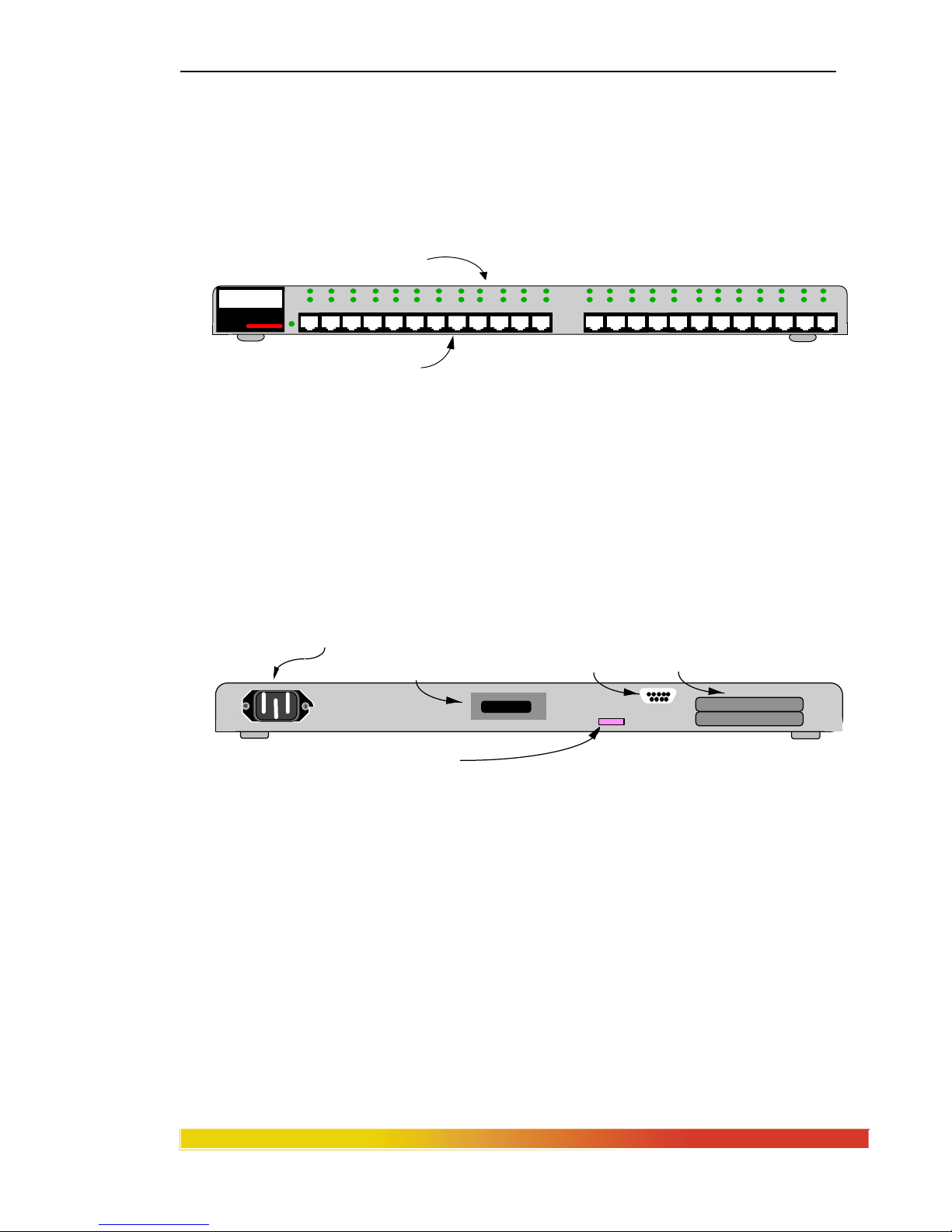
2.3 Magnum 3024 Hub - 24 RJ-45 Ports, One PM bonus port slot
The Magnum 3024 Hub provides 24 RJ-45 ports on the front of the unit plus a
Bonus Port slot on the rear which may be configured with any Magnum Port Module
(PM). User-segment wiring connections are made on the front of the unit, and statusindicator LEDs are located immediately above each of the 24 ports.
Figure 2.3a, Magnum 3024 Hub, Front View
The shielded RJ-45 port connectors on the front are electrically connected to
the metal case of the unit, and are helpful in reducing electromagnetic noise radiation
from the unit. (Note that the 10BASE-T wiring cable to the user may be unshielded or
shielded, Category 3 or 4 or 5. The choice of wiring type is left to the installer based on
preferences, standard practices and local or national wiring codes.)
Figure 2.3b, Magnum 3024 (and 3012), Rear View
2.3.1 Stacking Magnum 3000s
The rear of the Magnum 3000 Stackable Hubs have an Inter-Repeater Bus
(IRB) connector on the right side. The IRB interconnects stacked units with a shielded
ribbon cable, enabling all stacked Magnum 3000 units to operate as a single repeater.
There are two 34-pin IRB connectors on each unit: the bottom IRB connector
which is used to daisy chain the IRB to the stacked Magnum 3000 unit below (unused on
bottom unit in a Magnum 3000 stack); and the top IRB connector which is used to daisy
chain the IRB to the stacked Magnum 3000 unit above (unused on top unit in a Magnum
3000 stack). The IRB connectors for an non-stacked unit are unused.
Magnum 3000
Stackable Hub
GARRETT
Two LEDs (RX & LINK)
for each RJ-45 10BASE-T port.
Twenty-four RJ-45 10BASE-T Ports
Flashing LINK LED = Port is Partitioned
Flashing RX LED = Port Activity
Steady On LINK LED = Port is Operational
P1: Remote Terminal
RS-232 Port
(Embedded Agent Only)
AC Power
Connector
. . . . .
. . . .
Bonus Port Slot- C onfigurable via
Port Module (PM)
1 8
Inter-Repeater Bus (IRB)
P3 - Interface to unit above.
P4 - Interface to unit below.
P3
P
4
NOTE: P1 also used to setup IP address
and configuration files.
Eight (8) position dip switch.
1 - 6 = Address of Repeate r Unit (1-20)
7 = Not Used - Previously used to allow PC based SNMP Agent
8 = Not Used
Page 15

Magnum 3000 Stackable Hubs Installation and User Guide (07/06)
8
www GarrettCom com
..
The IRB ribbon cables supplied with each Magnum 3000 base unit are slightly
longer than the base unit height. Thus, an IRB cable segment has a small arc shape when
it is properly installed. It is possible to have some long IRB ribbon cable segments, up to
a few meters in length, for service loops and such. The operation of the stack will not be
impaired by longer IRB ribbon cables. Stacks with total IRB lengths of as much as ten
meters can be implemented. However, non-standard IRB cable lengths must be specially
made.
The IRB ribbon cables may be installed and/or removed while a Magnum 3000
unit is powered without causing damage to the electronic circuits in that unit or any
others in a Magnum 3000 stack. This is convenient for expanding a stack without
shutting down the network, and for performing diagnostics and service on potentially
faulty units operating in a stack. CAUTION
: disconnecting an IRB ribbon cable can
cause operational upsets by breaking the interconnection among the stacked units
previously operating as a single repeater and/or with one SNMP agent.
2.3.2 Segmenting a Magnum 3000 Stack with a Special Segmenting
Cable
Magnum 3000 Stackable Hubs are typically stacked as described in Section
2.3.1. However, it may be desirable to stack the 3000s so that they operate as separate
repeater units. This will normally be done to manage several separate hubs (or small
stacks) with a single 3000 AGT SNMP Agent box. In this situation, single units or
several small stacks of units may be connected using SRC Segmenting Cables (part
numbers SRC-2 and SRC-4, available as a spare part from GCI). Hubs connected via an
IRB Segmenting Cable do not transmit or receive normal Ethernet traffic through the
IRB.
GCI supports this non-standard configuration, making special stacking cable
available (see Models SRC-2 and SRC-4 in the Spare Parts Price List) to provide the
flexibility to break apart managed stacks into multiple collision domains for higher
performance, while still maintaining the advantages of one SNMP agent.
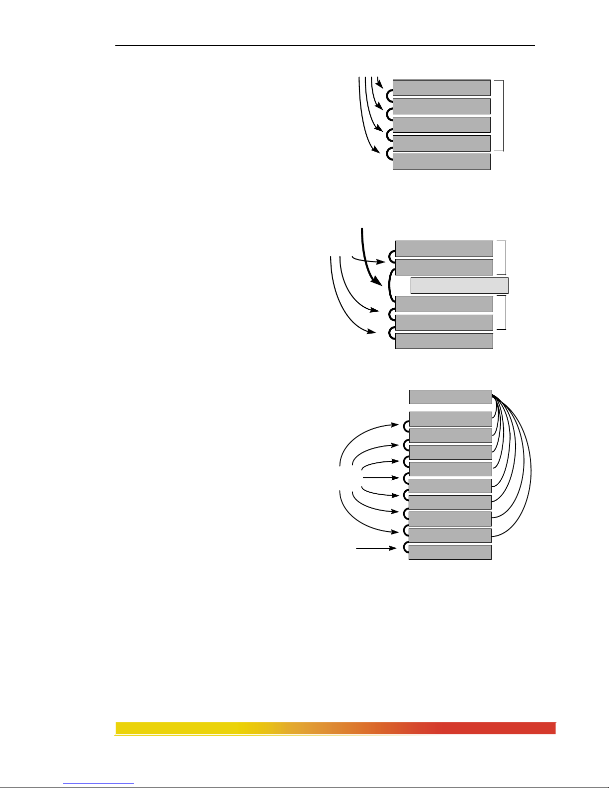
Consider the case where it is desired to divide a managed stack into two
segments and insert a local bridge to increase performance (see Figure 2.3.2a).
Normally, it would be necessary to add another SNMP agent to maintain full
management. However, using the special Segmenting cable option, it is possible to
remove one standard IRB cable and replace it with an SRC cable. This divides the stack
Page 16
Magnum 3000 Stackable Hubs Installation and User Guide (07/06)
9
www GarrettCom com
..
into two logical repeaters with separate
collision domains, while still passing SNMP
management data through the SRC so that the
agent can manage both repeaters. Then, a local
bridge can be installed between the two
repeaters using a port from each (for example,
using a bonus port from each repeater) to
provide traffic service between the
repeaters while maintaining full 10Mbps
bandwidth for the users on each repeater
stack. Figure 2.3.2a:
Stack
segmentation using an SRC
cable
The same result could also be
achieved by installing a Magnum
Bridge Port Module (BPM) into the
Bonus Port of one of the repeaters and
connecting it to a port on the other
repeater.
In another example, eight
3024 hubs in a managed stack are
individually segmented and a switching
hub is used as the traffic center.
Figure 2.3.2b: SRC cables segment a managed stack
for connection to switching hub ports.
This special configuration provides high bandwidth for the users on each 3024 hub, but
also provides the efficiency of a single SNMP agent for all of the 3024s. Note also that
Magnum 3012 units can be used with the special SRC segmenting cable, mixing with the
3024 models in configurations as desired.
Magnum 3024 hub
Magnum 3024 hub
Magnum 3024 hub
Magnum 3000-AGT
Magnum 3024 hub
frontrear
special
SRC cable
one
repeater
one
repeater
BRIDGE
IRB
cables
AFTER
one
repeater
Magnum 3024 hub
Magnum 3024 hub
Magnum 3024 hub
Magnum 3000-AGT
Magnum 3024 hub
frontrear
IRB
cables
BEFORE
Switching hub
Magnum 3024 hub
Magnum 3024 hub
Magnum 3024 hub
Magnum 3024 hub
front
rear
Magnum 3024 hu b
Magnum 3024 hu b
Magnum 3024 hu b
Magnum 3000-AG T
Magnum 3024 hu b
special
SRC cables
IRB
cable
Page 17
Magnum 3000 Stackable Hubs Installation and User Guide (07/06)
10
www GarrettCom com
..
NOTE: To differentiate the SRC cable from the IRB cable, GCI uses colored
ribbon cable for the SRC. The standard IRB cables are gray in color.
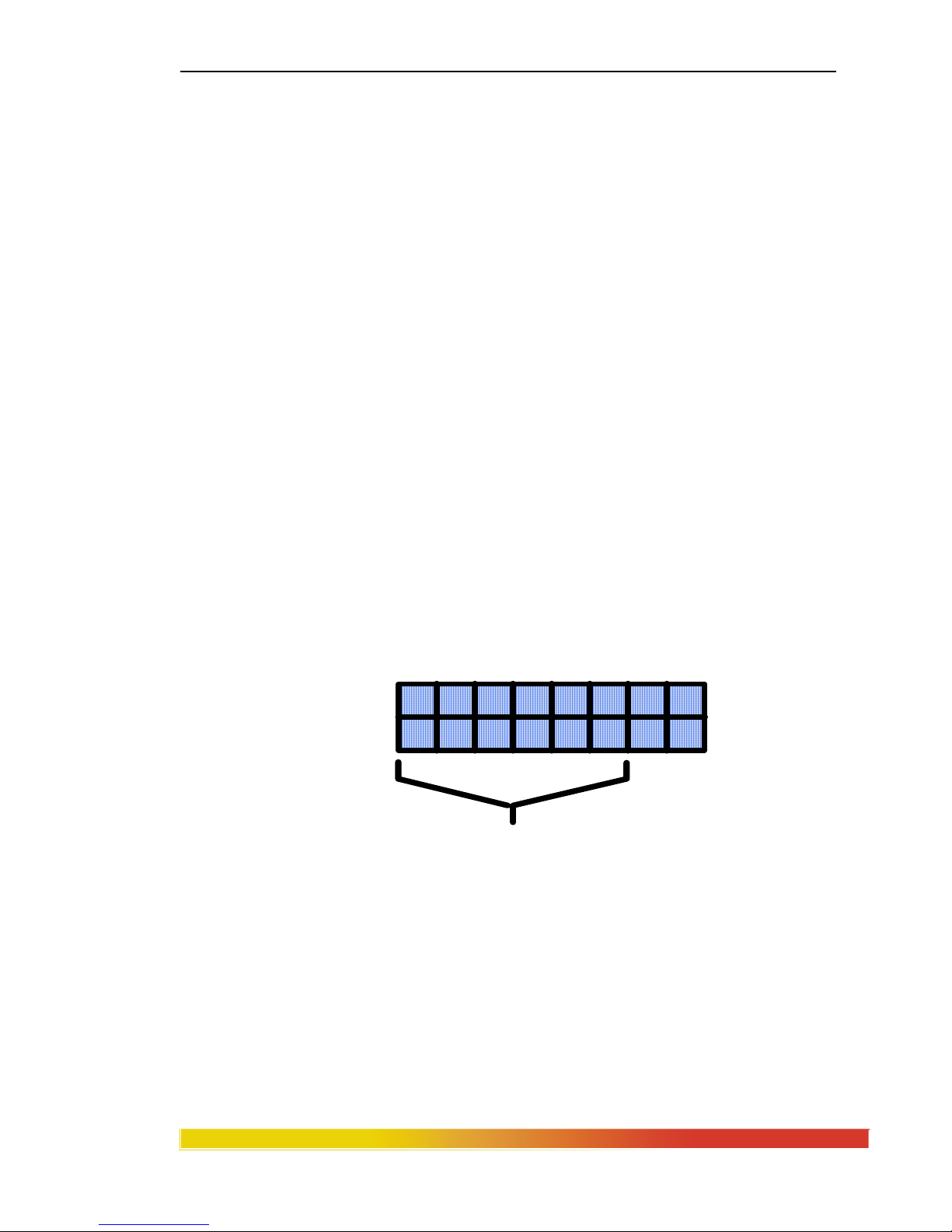
2.3.3 Group # Address Switch Settings, for Managed Units and Stacks
The eight-position DIP switch on the rear panel is used to give each unit in a
Magnum 3000 managed stack a unique Group # or "stack address". This Group #
follows the SNMP definition. (Group # addresses and the associated switch settings do
not matter if the units are unmanaged or "dumb"). See the illustration in Figure 2.3.3a.
Switches one through six are set at the time of installation to form a binary
number from 1 to 20. The switch positions may be moved using an instrument such as a
small screw driver, a pencil eraser or a fingernail. See Section 5.3 for a table of switch
settings vs. Group # address numbers.
The units in a managed stack should have Group # addresses beginning at 1
and proceeding up to the number of stacked units configured as one logical repeater at
the particular installation. The factory default address switch setting is usually "1", i.e.,
switch 1 ON and switches 2 through 6 OFF.
Figure 2.3.3a, Group # Address Switches, Enlarged Illustration
1 2 3 4 5 6 7 8
ON
OFF
Group # ADDRESS SWITCHES
Page 18

Magnum 3000 Stackable Hubs Installation and User Guide (07/06)
11
www GarrettCom com
..
The Group # switch settings must not be the same for any two Magnum 3000
units operating in one managed stack. Factory default switch settings cannot be relied
upon, and the user must check and/or change the Group # address switch settings for
each managed Magnum 3000 unit installed.
If a network management software package is in use, the Group # addresses set
for each Magnum 3000 physical unit will be reflected in the NMS displays, statistics and
controls that correspond to that unit's Group # address. (While non-sequential Group #
addresses will not prevent the units in a stack from working properly in the network, such
numbering tends to create problems for network administration and are therefore
discouraged accordingly.)
A Magnum 3000 stack may have from 2 to 20 active units (not including an
optional 3000-AGT unit, which could be the 21st box in a large stack). The stacked units
may be any combination of Magnum 3024s, 3012s,3000X and they may be arranged in
any order, physically and logically, for Group numbering purposes. Switch settings for
Group # addresses of zero and from 21 to 31 are not recognized by the NMS software in
a managed system, and the use of such Group # addresses is discouraged.
Switch 7 of the eight-position DIP switch is no longer used. In previous
versions of the product line it allowed the use of a PC-based SNMP AGENT. Switch 8
of the eight-position DIP switch is also unused.
The "P1" DB-9 connector on the upper part of the rear panel is used for a serial
port into the optional embedded SNMP agent board. If there is no embedded agent board
in a unit, "P1" is not present. See Section 5.1 for operational information on the optional
SNMP embedded agent board.
2.4 Magnum 3012 Hub - 12 RJ-45 Ports, One PM bonus port slot
The Magnum 3012 Hub provides 12 shielded RJ-45 ports on the front of the
unit, and is otherwise like the Model 3024 described above. Refer to the descriptive
material in Section 2.3 above.
Figure 2.4a, Magnum 3012 Hub, Front View
Magnum 3000
Stackable Hub
GARRETT
Two LEDs (RX & LINK)
for each RJ-45 10BASE-T port.
Twelve RJ-45 10BASE-T Ports
LINK
RX
Steady On LINK LED = Port is Operational
Flashing LINK LED = Port is Partitioned
Flashing RX LED = Port Activity
Page 19

Magnum 3000 Stackable Hubs Installation and User Guide (07/06)
12
www GarrettCom com
..
There is no upgrade from a Model 3012 to a Model 3024 since it would not
provide an economical method of adding ports. Note that the high degree of stacking of
Magnum 3000s - up to 20 units! - provides essentially unlimited expansion of the number
of users by adding more units to the stack.
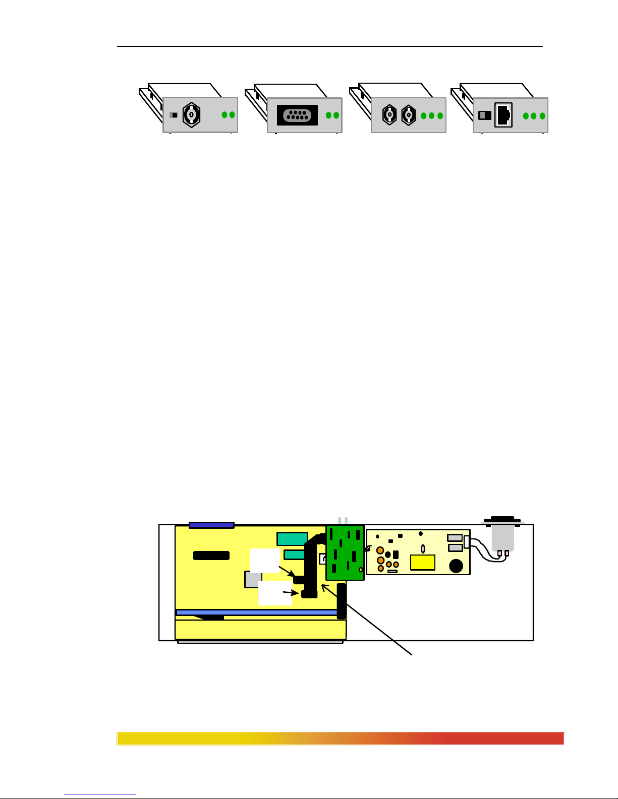
2.5 Rear Bonus Slot, Port Modules (PMs)
The Magnum 3012s and 3024s are each equipped with a bonus slot on the rear
of the unit. This slot may be optionally configured at the time of order with any one of
six Repeater Port Modules (RPMs) or four Bridge Port Modules (BPMs) to implement an
extra port. The optional bonus port may be used for any purpose, such as an Ethernet
coax backbone connection, or as a micro-bridge segment isolation unit. The RPMs
support any of six different media types: BNC (ThinNet), AUI (ThickNet), DTE (male
AUI), ST & SC (multi-mode Fiber), SMF (single-mode Fiber), and RJ-45 (UTP and
STP). The BPMs support any of four media types: BNC, AUI, ST, and RJ-45 (UTP and
STP). Normally, a maximum of one BPM should be used in a stack.
Each PM is equipped with its own media connector type. (For additional
information and specifications of individual PMs, see Section 4 of this manual.) The
assortment of standard network connector types for each RPM is shown in Figure 2.5a.
Figure 2.5a: Magnum RPM Modules for Bonus Ports
Left to right above: RPM-BNC, RPM-AUI (female),
RPM-DTE (male), RPM-FST, RPM-FSC, RPM-TP
Page 20
Magnum 3000 Stackable Hubs Installation and User Guide (07/06)
13
www GarrettCom com
..
The family of standard connector types for BPMs is shown in Figure 2.5b.
Figure 2.5b: Magnum BPM Modules for Bonus Ports
(left to right above) BPM-BNC, BPM-AUI, BPM-FST, BPM-TP
(Note: When an RPM-AUI type is configured as a bonus port, it is typically
implemented at the factory as an AUI connector with a ribbon cable to header pins on the
main board. The functionality is the same as the RPM-AUI card.)
For application flexibility, any of the Magnum PMs may be specified for
factory configuration at the time of order. It is also possible for the Bonus Port slot to be
configured in the field by a trained technician.
NOTE: When adding a Port Module to the Bonus Port slot in the field, it is necessary to
have a Port Module connector cable (part number PM-CBL available as a spare part from
GCI) in addition to the desired PM. See Figure 2.5a and 2.5b.
Figures 2.5a and 2.5b show the internal layout of the Magnum 3012 and 3024,
respectively. When installing a PM into the Bonus Port slot of the Magnum 3012, the
16-pin header labeled J1/B (also labeled RPM) should be used. The red stripe of the
PM connector cable should connect to pin 1of header J1/B.
Figure 2.5c: Magnum 3012 internal layout with configured Bonus Port
Bonus port for optional
PM card (BPM shown)
(Included only when PM is factory installed
May be ordered separately as part #CBL-PM
NOTE:
Use J1 (AUI) and for Basic AUI ports
Use J1/B (RPM) for PMs
J1
(AUI)
J1/B
(RPM)
Page 21

Magnum 3000 Stackable Hubs Installation and User Guide (07/06)
14
www GarrettCom com
..
When installing a PM into the Bonus Port slot of the Magnum 3024, use the
16-pin header labeled P1 (also labeled RPM) on the circuit board corresponding to ports
13-24. The red stripe of the connector cable should connect to pin 1 of header P1.
NOTE: The PM will still function if connected to header J1/B of the circuit board
corresponding to ports 1-12. However, this is not advised, as the port will not be
recognized by an SNMP Agent (if one is present).
Figure 2.5d: Magnum 3024 internal layout with configured Bonus Port
CBL-AUI
When the RPM-AUI is factory configured as a bonus port, it is implemented
with CBL-AUI, an AUI
connector with a ribbon cable, to
the 16-pin header J1 (AUI) on
the main board (Shown in both
figure 2.5a and 2.5b). Since the
AUI functionality is build onto
the main board, using CBL-AUI
is identical to the RPM-AUI. GCI recommends that RPM-AUI units should not get
installed in the bonus port of both 3012’s and 3024’s.
Bonus port for optional
PM card
(
BPM shown
)
PM Ribbon cable wi th 16 pin c onnec t or.
(Included only when PM is factory
Ma
y
be ordered separately as part # CBL-PM)
NOTE:
Use J1 (AUI) and for Basic AUI ports
Use P1 (RPM) for PMs
J1
(AUI)
P1
(RPM)
Pin 1 (red)
CBL-AUI
Page 22

Magnum 3000 Stackable Hubs Installation and User Guide (07/06)
15
www GarrettCom com
..
2.6 Features and Benefits, Magnum 3024 and 3012 Hubs
24 Port and 12 Port "Building Block" Hub Models
The 24 port units provide high density and low cost-per-port. The 12 port
units provide minimum add-on and entry-level system cost. The two units
may be combined and mixed in one stack.
Optional SNMP Management
Magnum 3000 Stackable Hubs may optionally be configured with an
SNMP agent. The SNMP agent is available as an embedded daughter
board mounted inside of a 3024 or 3012, or as a separate unit which is the
same physical size as a 3024 or 3012 unit and which supports a 3000
Stack. One SNMP agent serves all the Magnum 3000 units in one stack.
Stackable and Scaleable Configurations
Up to twenty Magnum 3000 units may be stacked, thus supporting up to
500 Ethernet segments operating as a single repeater. Both Hubs and an
SNMP Agent Box may easily be added to the stack for expansion of the
system. This provides for low initial cost and for graceful growth of
network systems.
Bonus Ports for any Ethernet Media Type
An optional rear-mounted bonus port may be configured with an RPM of
any media type, providing flexible connectivity to backbones or other
devices and nodes.
Optional Bridge Port Modules
The Magnum 3000 Stackable Hubs can be optionally configured with a
BPM as the bonus port. BPMs contain a miniature, self-learning local
bridge module capable of filtering and forwarding packets at full Ethernet
wire speed. A BPM may be used to bridge-isolate a local segment (such
as all of the nodes connected to a stack) having significant local inter-node
traffic, thus boosting overall network performance.
Rack-mount or Table-top, Front-ac cess Connectors and Status LEDs
Match the installation requirements of any environment with stacking
flexibility. Magnum 3000 Hubs may be mounted in a standard RETMA
rack or stacked on a shelf or table-top. The 10BASE-T ports and the
associated LEDs are adjacent to each other on the front of the units for
convenient status monitoring.
Small, compact units, 1 U
At only 1.75 inches (4.45 cm) high, Magnum 3024 and 3012 Hubs save
rack space and provide high port density in the wiring closet.
Proven reliability
Thousands of Magnum 3012 and 3024 Stackable Hubs have been installed
in critical applications world-wide for multiple years, and have
demonstrated exceptionally low failure rates. Calculated MTBF is up to
140,000 hours, depending on specific configuration and methodology.
Page 23

Magnum 3000 Stackable Hubs Installation and User Guide (07/06)
16
www GarrettCom com
..
2.7 Applications
The Magnum 3000 Stackable Hubs provide a flexible and cost-effective
solution to a variety of Ethernet networking applications. The combination of Stackable
Hubs and Stackable Mixed-Media Concentrators with optional SNMP is unique and
powerful.
Figure 2.7, taken from an installation in a small educational institution
building, illustrates some of the capabilities. The task was to economically network two
workgroups of PCs in Wing A and Wing C, and to consolidate them with an existing
group of UNIX workstation users in Wing B.
Here, a Magnum 3024 hub for 18 UNIX users in Wing B is being used to add
to and to support a ThinNet (10BASE2) segment. The BNC port is implemented via an
RPM-BNC in the rear bonus port. This hub is connected to a stack of two Magnum
3024's and one Magnum 3012 for 56 PC users in Wing A. A second segment of Fiber
(10BASE-FL) cable provides a link from the Wing A Magnum stack to an additional 22
users in Wing C. The optional future SNMP-based network manager can be connected to
any unit of the Magnum stack in Wing A. (A single SNMP agent may be added to the
Wing A stack as a future enhancement, for use with network management software.
Also note that BPMs in the bonus ports at Wings B and C can bridge-isolate this network
into 3 segments, each with essentially full bandwidth for high performance).
Because the high quality Magnum 3000s adhere to industry standards for
physical layer connectivity and for network management, they are popular choices for
small-to-medium-sized Ethernet networks where reliability and economy are required.
Figure 2.7: Magnum 3000s Consolidate an Educational Network System
Optional future
SNMP NMS
Magnum 3024 fo
r
22 PC users via UTP.
Magnum 3024 for
18 UNIX workstations
via AUI and BNC
(2) Magnum 3024’s & (1) Magnum 3012
stacked, for 56 PC users via UTP.
10BASE2
ThinNet
10BASE-FL
Fiber Segment
Win
g
A
Win
g
C
Win
g
B
Page 24

Magnum 3000 Stackable Hubs Installation and User Guide (07/06)
17
www GarrettCom com
..
3.0 Installation and Operation
Before installing the equipment, it is necessary to take the following precautions:
1) If the equipment is mounted in an enclosed or multiple rack assembly, the
environmental temperature around the equipment must be less than or equal to 50C.
2) If the equipment is mounted in an enclosed or multiple rack assembly, adequate air flow
must be maintained for proper and safe operation.
3) If the equipment is mounted in an enclosed or multiple rack system placement of the
equipment must not overload or load unevenly the rack system.
4) If the equipment is mounted in an enclosed or multiple rack assembly, verify the
equipment’s power requirements to prevent overloading of the building/s electrical circuits.
5) If the equipment is mounted in an enclosed or multiple rack assembly verify that the
equipment has a reliable and uncompromised earthing path.
6) If the intra-building wiring (cabling) is involved with this product(NEBS), then it is
recommended to have shielded cable and the shield is grounded at both ends.
7) This equipment is for installation only in a Restricted Access Location (dedicated
equipment room service closet and the like) in accordance with the National Electrical
Code.
3.1 Connecting Ethernet Media
The Magnum 30000 Hubs are specifically designed to support all Ethernet
media types via the Bonus Port options. There is a family of Port Modules (PMs). The
procedures for connecting each media and connector type are as follows:
3.1.1 Connecting Twisted Pair (RJ-45, Unshielded or Shielded)
The following procedure describes how to connect a 10BASE-T twisted pair
segment to the RJ-45 port on the front panel of the 3000 hub or to the RPM-TP or BPMTP of the 3000X or bonus port. The procedure is the same for both unshielded and
shielded twisted pair segments.
1. Using standard 10BASE-T media, insert either end of the cable with an RJ-45
plug into the RJ-45 connector. Note that, even though the TP connector is
shielded, either unshielded or shielded 10BASE-T cables and wiring may be
used.
2. Connect the other end of the cable to the corresponding device.
3. When proper connection and power have been established, the port’s LINK LED
will illuminate GREEN.
NOTE: The Magnum RPM-TP and BPM-TP are equipped with a cross-over slide
switch to accommodate repeater-to-repeater connections without special crossover connectors. Set the slide switch to the “down” position for normal twisted
pair cable segments from the hub port to a user device. Set the slide switch to
the “up” position for cascaded or up-link segment connections to another
repeater or hub in the network. Verify proper switch position by noting that the
port’s LINK LED will illuminate when proper link is established.
Page 25

Magnum 3000 Stackable Hubs Installation and User Guide (07/06)
18
www GarrettCom com
..
3.1.2 Connecting ThickNet 10BASE5 (AUI)
Using the steps below as a guide, attach a new or existing 10BASE5 ThickNet
drop-cable directly to the AUI connector on the RPM-AUI or BPM-AUI port.
1. Plug the cable’s male end into the female AUI connector on the PM-AUI card.
2. Engage the AUI connector slide lock to insure maximum connectivity.
3. Connect the opposite end of the cable into a network AUI port. (This could be a
network backbone transceiver, a hub or fan-out with an AUI port, or an AUI Port
Module in a concentrator.)
The AUI port may also used for connecting to other Ethernet devices using
standard AUI cabling. In this type of situation, it is important to consider the AUI
segment length to the attached device, including any cascading. See “Product
Description, RPM-AUI” for additional details.
3.1.3 Connecting ThinNet 10BASE2 (BNC)
Connect the ThinNet coax cable to the BNC connector on the Magnum RPMBNC or BPM-BNC card in the same manner as is done for any standard BNC
connection. The PM-BNC port is specially equipped with an internal termination switch
on the front of the card (see Section 4.1 for a description of this switch). This eliminates
the need to use a "tee" connector when the BNC cable is ending at the connection to this
PM. Some applications may require a "tee" connector, used as a tap, to allow the
10BASE2 coax segment to continue on past the PM-BNC connection.
3.1.4 Connecting Drop Cable 10BASE5 (DTE)
Using the steps below as a guide, attach the 10BASE5 drop-cable directly to the
DTE connector on the RPM-DTE port.
1. Plug the cable’s female end into the male DTE connector on the RPM-DTE card.
2. Engage AUI connector slide lock (on the cable) to insure maximum connectivity.
3. Connect the opposite end of the cable into a network AUI port. (This
could be a server, router, bridge, hub, or UNIX workstation.)
3.1.5 Connecting Fiber Optic 10BASE-FL and FOIRL (ST-type,
“Twist-Lock")
The following procedure applies to FOIRL and 10BASE-FL applications
using an RPM-ST or BPM-ST card with ST-type fiber connectors. (The
primary difference between FOIRL and 10BASE-FL for users is the
maximum distance allowed. 10BASE-FL is used for a fiber segment length
of up to 2000m, while FOIRL is used for fiber segments of up to 1000m in
length.)
Page 26

Magnum 3000 Stackable Hubs Installation and User Guide (07/06)
19
www GarrettCom com
..
1. Before connecting the fiber optic cable, remove the protective dust caps from the
tips of the connectors on the PM-ST. Save these dust caps for future use.
2. Wipe clean the ends of the dual connectors with a soft cloth or lint-free lens tissue
dampened in alcohol. Make certain the connectors are clean before connecting.
Note: One strand of the duplex fiber optic cable is coded using color bands
at regular intervals; you must use the color-coded strand on the
associated ports at each end of the fiber optic segment.
3. Connect the Transmit (TX) port (light colored post) on the Magnum PM-FST to
the Receive (RX) port of the remote device. Begin with the color-coded strand
of the cable for this first TX-to-RX connection.
4. Connect the Receive (RX) port (dark colored post) on the PM-FST to the (TX)
Transmit port of the remote device. Use the non-color coded fiber strand for this.
5. The LINK LED on the front of the PM-FST will illuminate when a proper
connection has been established at both ends (and when power is ON in the
unit). If LINK is not lit after cable connection, the normal cause is improper
cable polarity. Swap the fiber cables at the Port Module connector to remedy
this situation.
3.1.6 Connecting Fiber Optic (SC-type, "Snap-On")
The same five-step procedure as for fiber ST-type applies to FOIRL and
10BASE-FL applications using an RPM-SC card used with SC-type fiber connectors.
Follow the five steps as described in the Section 3.3.5 above.
When connecting fiber media to SC connectors, simply snap on the square
male connector into the SC female jack of the device until it clicks and secures.
3.1.7 Connecting Single-Mode Fiber Optic (SMF)
When using the RPM-SMF, be sure to use single-mode (small diameter) fiber
cable. The same five-step procedure as for multi-mode ST-type applies to single-mode.
3.1.8 Power Budget Calculations for Magnum 3000s RPM’s with Fiber
Media
Receiver Sensitivity and Transmitter Power are the parameters necessary to
compute the power budget. To calculate the power budget of different fiber media
installations using Magnum products, the following equations should be used:
OPB (Optical Power Budget) = P
T
(min) - PR(min)
where P
T
= Transmitter Output Power, and PR = Receiver Sensitivity
Worst case OPB = OPB - 1dB(for LED aging) - 1dB(for insertion loss)
Worst case distance = {Worst case OPB, in dB} / [Cable Loss, in dB/Km]
where the “Cable Loss” for 62.5/125 and 50/125
m
(M.m) is 2.8 dB/km,
Page 27

Magnum 3000 Stackable Hubs Installation and User Guide (07/06)
20
www GarrettCom com
..
and the “Cable Loss” for 100/140 (Multi-mode) is 3.3 dB/km,
and the “Cable Loss” for 9/125 (Single-mode) is 0.5 dB/km
The following data has been collected from component manufacturer’s (HP’s and
Siemens’) web sites and catalogs to provide guidance to network designers and installers.
Fiber
Port
Module
Speed,
Std.
Mode
Std.
km
fdx
(hdx)
Wave
-
length
nm
Cable
Size
m
X’mitr
Output
P
T ,
dB
R’cvr
Sens.
P
R ,
dB
Worst
OPB,
dB
Worst*
distance
Km, fdx
typical
OPB,
dB
typical*
distance
Km, fdx
RPM-FST,
FSC
10 Mb
FL
Multi-
mode2 (2)
850
62.5/125
100/140
50/125
-15.0
-9.5
-19.5
-31
-31
-31
14
19.5
9.5
5
5.9
3.4
17
23.5
13.5
6
7
4.8
RPM-
SMF(ST)
10 Mb
FL
Single-
mode
10
(5)
1300 9/125 -30 -39 7 14 13 26
* Note: The use of either multi-mode or single-mode fiber to operate at 100Mbps speed
over long distances (i.e., in excess of approx. 400 meters) can be achieved
only
if the following factors are both applied:
The 100Mb fiber segment must operate in full-duplex (FDX) mode, i.e. the
full-duplex (factory default) setting for 100Mbps fiber ports must be used,
and
The worst-case OPB of the fiber link must be greater than the fiber cable’s
passive Attenuation.
(Attenuation = Cable loss + LED aging loss + Insertion loss + safety factor)
3.1.9 Rack-mounting
Installation of a Magnum 3000s Hub in a 19” rack is a simple procedure. The
units are 1U (1.70”) high. When properly installed, the front-mounted LED status
indicators should be in plain view and easy to read. Rack-mount installation requires
special 19” rack-mounted
brackets and screws
(included with each 3000s
unit). The brackets attach to
the front sides of the Hub,
which is then fastened into a standard 19” RETMA rack.
The 23” brackets and ETSI brackets are also available (optional) for Rackmounting of Magnum 3000 units. The 23” brackets are more popular in the Telco
industry where they are a standard for Central Office Rack-mounting purposes. The 23”
brackets are mainly used for larger equipment assemblies in rack mounting frames, and
are frequently accessed in operation from both sides.
Magnum 3000
Stackable Hub
GARRETT
Page 28

Magnum 3000 Stackable Hubs Installation and User Guide (07/06)
21
www GarrettCom com
..
The ETSI (European Telephone Standard) brackets are similar to the 19”
brackets but use
metric dimensions.
The
optional 23”
brackets and the
ETSI brackets
come as a pair in a
package along with
the necessary
screws for
attaching the
brackets to the
sides of the
Magnum Hub unit.
Fig 3.1 Multiple Magnum 3000 units rack-mounted in a 23” Rack-mount frame
The following instructions need to be follow up before installationsA) Elevated Operating Ambient - If installed in a closed or multi-unit rack assembly, the
operating ambient temperature of the rack environment may be greater than room
ambient. Therefore, consideration should be given to installing the equipment in an
environment compatible with the maximum ambient temperature (Tma) specified by the
manufacturer.
B) Reduced Air Flow - Installation of the equipment in a rack should be such that the
amount of air flow required for safe operation of the equipment is not compromised.
C) Mechanical Loading - Mounting of the equipment in the rack should be such that a
hazardous condition is not achieved due to uneven mechanical loading.
D) Circuit Overloading - Consideration should be given to the connection of the
equipment to the supply circuit and the effect that overloading of the circuits might have
on overcurrent protection and supply wiring. Appropriate consideration of equipment
nameplate ratings should be used when addressing this concern.
E) Reliable Earthing - Reliable earthing of rack-mounted equipment should be
maintained. Particular attention should be given to supply connections other than direct
connections to the branch circuit (e.g. use of power strips)."
Magnum 3000
Stackable Hub
GARRETT
Magnum 3000
Stackable Hub
GARRETT
Magnum 3000
Stackable Hub
GARRETT
Magnum 3000
Stackable Hub
GARRETT
Page 29

Magnum 3000 Stackable Hubs Installation and User Guide (07/06)
22
www GarrettCom com
..
4.0 Introduction - Magnum Port Modules
This chapter describes each Port Module (PM), including appearance,
functionality, and status displays.
4.1 Inspecting the Package and Product
This section applies only to PMs shipped as separate items, i.e., only to PMs
not factory installed in a Magnum 3000 Stackable Hubs bonus port slot.
Examine the shipping container for obvious damage prior to installing a PM;
notify the carrier of any damage which you believe occurred during shipment or delivery.
Inspect the contents of this package for any signs of damage and ensure that the items
listed below are included.
This package should contain:
One or more PMs.
Remove the PM(s) from the shipping container. Be sure to keep the shipping
container should you need to ship any of the PMs separately at a later date.
In the event there are items missing or damaged contact your supplier. If you
need to return the unit, use the original shipping container if possible. Refer to Chapter 5
for specific return procedures.
4.2 Product Description, Port Modules
An important feature of the Magnum 3000 Stackable Hubs is the use of
individual Port Modules (PMs) for flexible mixed-media connectivity. The Magnum
PMs are compact interface cards designed to support every standard Ethernet media type.
Each PM provides one port for connecting one Ethernet segment with its individual
connector type and media. There are a total of six Repeater Port Module (RPM) cards,
plus a face plate. They are:
RPM-BNC, RPM-AUI, RPM-DTE RPM-FST (or FSC), RPM-SMF, RPM-TP
There are also four different Bridge Port Module (BPM) cards. They are:
BPM-BNC BPM-AUI BPM-TP BPM-FST
Each PM is individually described as follows.
Page 30

Magnum 3000 Stackable Hubs Installation and User Guide (07/06)
23
www GarrettCom com
..
4.2.1 RPM-BNC
The Magnum RPM-BNC repeater module is equipped with a standard
10BASE2 coax connector. This RPM performs full IEEE 802.3 repeater functionality
and is used for 10BASE2 ThinNet (commonly referred to as BNC) connections.
The RPM-BNC module is designed with a special switch-selectable internal
termination function that eliminates the need for a "tee" connector and a 50 ohm
terminator. To take advantage of internal termination, the slide switch should be in the
"DOWN" (or right-side) position. In this configuration, the 10BASE2 segment is
directly Magnum RPM-BNC
attached to the BNC port where it is internally terminated. When the switch is in the
"UP" (or left-side) position, the BNC port requires a "tee" connector (not supplied) and a
50 ohm terminator for proper termination. Certain applications may require a "tee"
connector, used as a tap, to allow the 10BASE2 coax segment to continue on past the
RPM-BNC connection.
The RPM-BNC module includes one partition (PART) and one receive (RX)
LED, which are visible beside the connector. The PART LED illuminates AMBER to
indicate that the segment
has been automatically
partitioned. As soon as
normal reception resumes,
the segment will be
automatically reestablished. The RX LED
illuminates GREEN
intermittently to indicate data is being received.
Important Note:
for the RPM-BNC Termination Switch -
DOWN (or right) = Internally Terminated, UP (or left) = "T" Connector required.
4.2.2 RPM-AUI
1
2
Internal Termination
Slide Switch
Standard BNC
10BASE2 Connector
Partition LE D
Receive LED
1
2
Page 31

Magnum 3000 Stackable Hubs Installation and User Guide (07/06)
24
www GarrettCom com
..
The RPM-AUI is equipped with a 15 pin female AUI connector and a slidelock, and performs full IEEE 802.3 repeater functionality. It is used to provide
connectivity with a 10BASE5
(ThickNet) backbone or to any AUI
segments. A transceiver is required
when connecting to a ThickNet
segment and the RPM-AUI supports
this convention. The RPM-AUI is
also a "universal" Ethernet media
interface as it may be used with a
variety of different mini-transceivers
to provide connectivity to any media type. The Magnum RPM-AUI card is also used for
connecting Ethernet devices using standard AUI cabling. In this situation, it is important
to consider the AUI segment length or distance to the attached device (see details below).
RPM-AUI cards are equipped with Partition (PART) and Receive (RX) LEDs which
function the same as the identical LEDs on the RPM-BNC (see above).
NOTE: When the RPM-AUI is factory configured as a bonus port, it is
implemented as an AUI connector with a ribbon cable to special pins on
the main board. The functionality of this is identical to the RPM-AUI.
The maximum transmission distance between a backbone transceiver equipped
with an AUI connector and an RPM-AUI port will vary. When an AUI cable is used to
connect the Magnum RPM-AUI directly to a backbone transceiver, the maximum AUI
segment length is allowed. If the RPM-AUI is connected to a transceiver that has been
cascaded from another transceiver, the maximum AUI segment length is reduced.
According to Ethernet standards, the maximum distance from the transceiver
AUI connector and the attached device (Magnum RPM-AUI) is 50m (165 ft.). The AUI
segment maximum length is reduced in cascaded configurations. See the following note.
Important Note: The maximum transmission distance is decreased by 6m
(20 ft.) for every additional level of network transceiver device "dropped"
or "cascaded" from the original backbone transceiver tap.
Standard 15-pin
female AUI,
Partition LED
Receive LED
1
2
2
1
Magnum RPM-AUI
with slide-lock
Page 32

Magnum 3000 Stackable Hubs Installation and User Guide (07/06)
25
www GarrettCom com
..
The RPM-AUI connector supports standard IEEE signals, as follows:
Table 3.2.2: AUI Pin Assignments
Pin Function Pin Function
1 Control In Circuit Shield 10 Data Out Circuit B
2 Control In Circuit A 11 Data Out Circuit Shield
3 Data Out Circuit A 12 Data In Circuit B
4 Data In Circuit Shield 13 Voltage Plus (+)
5 Data In Circuit A 14 Voltage Shield
6 Voltage Common 15 Control Out Circuit B
7 Control Out Circuit A SHELL Protective Ground
8 Control Out Circuit Shield (conductive shell)
9 Control In Circuit B
NOTES:
1) Voltage Plus (pin #13) and Voltage Common (pin # 6) use a single
twisted pair in the AUI cable.
2) Pins 4, 8, 11 and 14 may be connected to pin #1.
4.2.3 RPM-DTE
The Magnum RPM-DTE is a module equipped with a 15-pin male DTE
connector with lock posts. (The RPMDTE is a mating connector for the
RPM- AUI which has a 15-pin female
connector and slide locks. The pin
assignments of
the two are the same). The RPM-DTE
card is designed to support direct
connections (no transceiver Magnum RPM-DTE
required) using AUI drop cables to
any device that is equipped with an AUI port. Examples of such devices include servers,
router, bridges, hubs, and UNIX workstations.
1
2
Partition LED
Receive LED
1
2
Standard 15-pin
male "AUI"
Page 33

Magnum 3000 Stackable Hubs Installation and User Guide (07/06)
26
www GarrettCom com
..
4.2.4 RPM-FST (Fiber ST, Twist-lock Connector)
The Magnum RPM-FST is a multi-mode fiber optic module equipped with a
dual ST-type connector. It functions as
an IEEE 802.3 full repeater to support
10BASE-FL and FOIRL network
segments. When used for 10BASE-FL
segments, this module supports fiber
optic transmission distances up to
2000m. For FOIRL applications, it
supports fiber segments of up to 1000m
in length. The RPM-FST includes full
transceiver Magnum RPM-FST
functionality and does not require an external transceiver device. In addition to Partition
(PART) and Receive (RX) LEDs, a LINK LED indicates proper connectivity with the
remote device.
NOTE: The RPM-FST/FSC circuit board contains a six pin jumper which controls the
intensity of the transmitted signal. By default, the jumper is placed across pins 1 and 2.
The jumper may be set as follows to accommodate distances of up to 4 km:
JUMPER ACROSS
DISTANCES SUPPORTED
1 - 2 0 - 2 km
3 - 4 0.5 - 3 km*
5 - 6 1.5 - 4 km*
When distances of less than 2
km are needed, the jumper
should be placed across pins 1
and 2.
*When fiber cable distances
of more than 2 km are
selected, the minimum cable
length must also be increased,
as shown in the table above.
1
2
3
1
LINK Partition Receive
2
3
10BASE-FL, FOIRL
ST Connectors
1 2
3 4
5 6
J1
DEFAULT
Page 34
Magnum 3000 Stackable Hubs Installation and User Guide (07/06)
27
www GarrettCom com
..
4.2.5 RPM-FSC (Fiber SC, Snap-in Connector)
The Magnum RPM-FSC is also a multi-mode fiber optic repeater module,
similar to the RPM-FST. It has the same LEDs
indicating port partitioned (PART), receive activity
(RX), and link operational (LINK). It has the same
jumper settings for extra distance in certain
circumstances.
While the functionality of the these two
modules is the same, the RPM-FSC is equipped with
an SC-type "snap-in" connector instead of an ST-type "twist-lock" connector. Please
refer to Section 3.2.4. for details.
Magnum RPM-FSC
4.2.6 RPM-SMF (Single-mode Fiber)
The Magnum RPM-SMF is a single-mode fiber optic module equipped with a
dual ST-type connector. It functions as a full repeater to support single-mode fiber
networks. The RPM-SMF supports fiber
optic transmission distances of up to 10
Km. The RPM-SMF includes full
transceiver functionality and does not
require an external transceiver device.
This module is equipped with
PART, RX, and LINK LEDs identical to
those of the RPM-FST. To distinguish
the single-mode RPM-SMF from the multi-mode Magnum RPM-SMF
RPM-FST, the label “Sgl. M.” is at the top of the faceplate of the RPM-SMF. As an
additional indicator, a multi-mode TX port emits light (red in color) that is in the visible
spectrum and which can be seen by looking into the port with the power on and with no
cable connected. The single-mode TX port emits light outside of the visible spectrum
and will always look dark to the human eye.
Note: Be sure to use single-mode fiber optic cable with this module. Single-mode fiber
cable has a smaller diameter than multi-mode fiber cable (2/15 - 8/60 microns for singlemode, 50/125 or 62.5/125 microns for multi-mode, where xx/xx are the diameters of the
core and the core plus the cladding respectively).
10BASE-FL, FOIRL
SC Connectors
1
3
2
1
2
3
1
LIN K Partitio n Re ceiv e
2
3
Single-mode
ST C o nn ec tors
Page 35

Magnum 3000 Stackable Hubs Installation and User Guide (07/06)
28
www GarrettCom com
..
NOTE: The RPM-SMF circuit board contains a six pin 3-position jumper, but
the jumper is only to be placed across pins 5 & 6. The others are not used.
JUMPER ACROSS
DISTANCES
SUPPORTED
1 - 2 not used
3 - 4 not used
5 - 6 0 - 10 Km
4.2.7 RPM-TP (Twisted Pair)
The Magnum RPM-TP card supports Ethernet twisted pair segments of any
standard length. It is equipped with a single RJ-45 connector. The RJ-45 connector is
shielded to minimize
emissions and will
allow both unshielded
twisted pair (UTP) and
shielded twisted pair
(STP) segment
connections.
Magnum RPM-TP
The RPM-TP module is also equipped with a Media Dependent
Interface-Crossover (MDI-X) slide switch to allow for cascaded connections. This
feature eliminates the need for a special twisted pair crossover cable.
With the switch in the UP position, the RPM-TP port is used for cascaded and
up-link connections (i.e.: a connection to another repeater or hub or concentrator
typically.) When used for segments going to workstations and other user device
connections, the MDI-X switch should be in the DOWN position.
The RPM-TP will support 10BASE-T unshielded twisted pair wiring (UTP)
environments with maximum segment distances up to 100m (325 ft.), or shielded twisted
pair wiring (STP) of 150m (500 ft.). This module is designed with internal transceiver
functionality. The RPM-FST has LINK, PART, and RX LEDs.
1 2
3 4
5 6
J1
DEFAULT
Shielded RJ-45
Connector
1
2
3
1
LINK Partition Receive
2
3
MDI-X
Cross-Over
Slide Switch
Page 36

Magnum 3000 Stackable Hubs Installation and User Guide (07/06)
29
www GarrettCom com
..
Important Note: For the RPM-TP MDI-X Crossover Switch DOWN(or Right) for workstations and user connections.
UP (or Left) for Up-Link connections to other hubs, etc.
(To help recall the right TP switch position, remember "up for up-link" ! )
The RJ-45 pins normally (TP crossover switch DOWN) are per the standard for hubs-tousers twisted pair wiring: 1 = receive+, 2 = receive-, 3 = transmit+, 6 = transmit-, other
pins not used. When the TP crossover switch is UP, the pins of the RJ-45 port are per the
standard for up-links using twisted pair wiring, i.e., the transmit and the receive pairs are
exchanged: 1 = transmit+, 2 = transmit-, 3 = receive+, 6 = receive-, other pins not used.
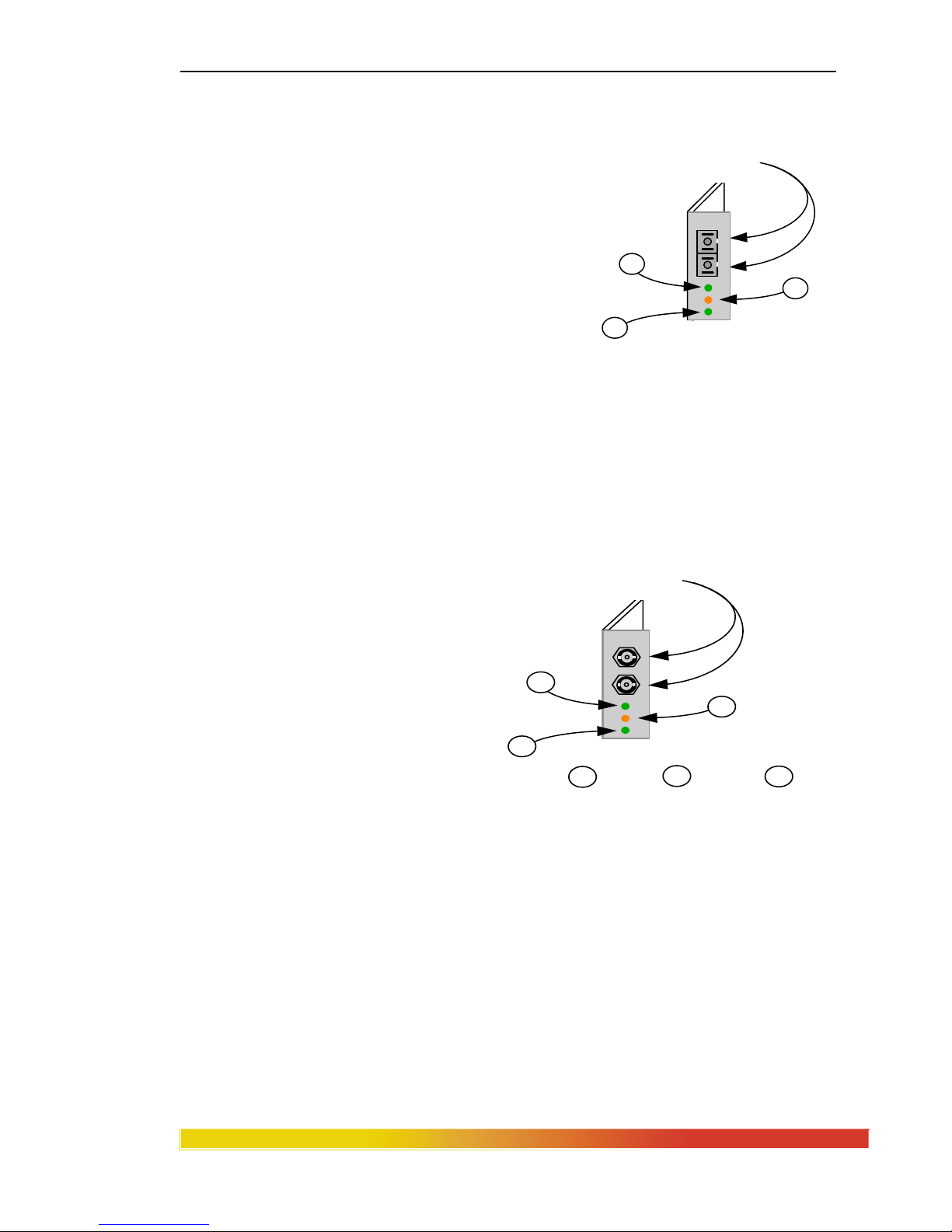
4.2.8 BPM-BNC
The Magnum BPM-BNC bridge module is equipped with a standard 10BASE2
coax BNC connector. This BPM is self-learning and filters and forwards packets at full
Ethernet wire speed. This module is used for 10BASE2 connections and is designed to
isolate the local segment (i.e., the local nodes connected to the Magnum unit housing the
BPM internally) from the connecting network (i.e., the nodes of external users and
devices connected through the BPM’s media connector).
The BPM-BNC module is designed with a special switch -selectable internal
termination function that eliminates the need for a "tee" connector and a 50 ohm
terminator. For switch details, refer to the RPM-BNC section, 3.2.1
The BPM-BNC module includes an FWD-I LED and an FWD-X LED, which
are visible from the front. The FWD-I
LED blinks GREEN to indicate that
packets are being forwarded INTO the
local Magnum hub or stack.. The FWDX LED blinks GREEN to indicate that
packets are being forwarded OUT of the
local Magnum hub or stack.
Magnum BPM-BNC
Standard BNC
10BASE2 Connector
Internal Termination
Slide Switch
1
2
FWD-X LED
FWD-I LED
2
1
Page 37

Magnum 3000 Stackable Hubs Installation and User Guide (07/06)
30
www GarrettCom com
..
4.2.9 BPM-AUI
This local-bridge module is equipped with a 15 pin female AUI connector and
a slide-lock. It is self-learning and filters and forwards packets at full Ethernet wire
speed. It is used to provide segment
isolation from a 10BASE5 (ThickNet)
backbone or any AUI segments. A
transceiver is required when connecting to a
ThickNet segment and the BPM-AUI
supports this convention.
The BPM-AUI card is equipped
with one FWD-I LED and one Magnum BPM-AUI
FWD-X LED, which are identical to those of the BPM-BNC (Section 2.2.7).
The RPM-AUI connector supports standard IEEE signals, which are
summarized in Table 3.2.2 of Section 3.2.2.
4.2.10 BPM-FST
The Magnum BPM-FST is a multi-mode fiber optic local-bridge module
equipped with a dual ST-type connector. It is self-learning and filters and forwards
packets at full Ethernet wire speed. When
used for 10BASE-FL segments, this module
supports fiber optic transmission distances
up to 2000m. For FOIRL applications, it
supports fiber segments of up to 1000m in
length. The BPM-FST includes full
transceiver functionality and does not
require an external
Magnum BPM-FST
transceiver device. The BPM-FST has three status LEDs. FWD-I and
FWD-X are identical to those of the BPM-BNC (Section 2.2.7). In addition, this module
has a GREEN LINK LED, that is always on when the attached fiber link is operational.
FWD-X LED
FWD-I LED
2
1
Standard 15-pin
female AUI
with slide-lock
1
2
10BASE-FL, FOIRL
ST Connectors
FWD-X LED
FWD-I LED
LINK LED
2
1
3
3
2
1
Page 38

Magnum 3000 Stackable Hubs Installation and User Guide (07/06)
31
www GarrettCom com
..
4.2.11 BPM-TP
The Magnum BPM-TP card is equipped with a single RJ-45 connector and
supports Ethernet twisted pair segments of any standard length. The RJ-45 connector is
shielded to minimize emissions and will allow both unshielded twisted pair (UTP) and
shielded twisted pair (STP) segment connections.
The BPM-TP module is also equipped with a Media Dependent InterfaceCrossover (MDI-X) slide switch to allow for cascaded connections. This feature
eliminates the need for a special twisted-pair crossover cable. For MDI-X switch details,
refer to the RPM-TP section, 3.2.7.
The BPM-TP will support 10BASE-T unshielded twisted pair wiring (UTP)
environments with maximum
segment distances up to 100m (325
ft.), or shielded twisted pair wiring
(STP) of 150m (500 ft.). This
module is designed with internal
transceiver functionality. The
LINK, FWD-I, and FWD-X LEDs
of this BPM are the same as those of the Magnum BPM-TP
BPM-FST (Section 3.2.10).
Shielded RJ-45
Connector
FWD-X LED
FWD-I LED
LINK LED
2
1
3
MDI-X Cross-over
Slide Switch
3
1
2
Page 39

Magnum 3000 Stackable Hubs Installation and User Guide (07/06)
32
www GarrettCom com
..
5.0 Introduction - Simple Network Management Protocol (SNMP)
Agents
This chapter describes the Magnum 3000 SNMP agent products.
5.1 SNMP Agents Description
There are two configuration options (versions) of the Magnum SNMP
hardware agent. Both versions follow standard MIB I and MIB II protocol conventions.
In one version, the Magnum SNMP agent is offered as an embedded board
(Model 3000-MB) which resides directly within the Magnum 3024 or 3012 box. In the
alternate version, the Magnum SNMP agent board is available in a separate box (Model
3000-AGT) that is the same size as a 3024 or 3012 unit, and has its own internal power
supply and Inter Repeater Bus (IRB) connections to fit it into a Magnum 3000 stack.
The "MB" version is ideal for agents that are part of the initial configuration, and for the
smaller stacks and single-unit systems. The "AGT" version is convenient for field addons of the SNMP agent option and for large stacks.
Magnum SNMP agents support all standard basic SNMP commands
(GetRequest, GetNextRequest, GetRespose, SetRequest and Trap), and allow monitoring
and changing of the target device's configuration and parameters as well as reporting the
device alarms from a network management station.
5.1.1 Embedded SNMP Agent, Model 3000-MB
The embedded Magnum SNMP agent is a daughter board that is directly
attached to the master printed circuit board inside each Magnum 3012 or 3024 unit. The
embedded agent essentially consists of an embedded computer configuration built around
a 386 CPU, and is designed with an interface to the Inter-Repeater-Bus (IRB). This
allows all units within a Magnum stack to be managed from a single SNMP agent via the
IRB that interconnects the stack.
The embedded agent board is equipped with an externally accessible 9-pin RS232 serial connector, referred to as "P1". This connector may be used to set the IP
address and configuration files of the Magnum agent if necessary.
EPROMs on the agent board contain fixed data and program firmware. The
Standard Repeater MIB ( MIB I & MIB II) and the Monitor and Address Tracking MIB
Page 40

Magnum 3000 Stackable Hubs Installation and User Guide (07/06)
33
www GarrettCom com
..
extensions data are in this firmware. The firmware in the EPROMs performs the data
collection and execution functions, and operates as the local controller and interface to
the network manager.
5.1.2 Separate Agent Box, Model 3000-AGT
The Magnum 3000 SNMP Agent Box operates the same as the embedded
board agent. It is packaged as a separate unit, enclosed in a box that is the same
dimensions as a 3024 or 3012 so that it fits neatly into a Magnum 3000 stack. It is a
complete modular unit with its own internal auto-ranging power supply.
The Magnum 3000-AGT agent box is connected into a stack by the InterRepeater Bus (IRB). There are two IRB connectors at the right-rear, permitting the agent
box unit to be installed at the bottom or top of a stack using one IRB connector, or to be
inserted into the middle of a stack using two IRB connectors. The IRB cable connectors
are made with "notches / keys" to insure a proper connection.
The agent logically resides on the IRB and will not be visible to network
management software packages as a separate port or user. For network integrity, the
agent is designed so that it cannot be disconnected by network managers accidentally or
purposefully. Similarly, the agent operates in the stack attached to the IRB and does not
need to use a port in any attached Magnum 3000 unit to be connected.
5.1.3 Standard Repeater MIB and Extensions
Magnum 3000
SNMP Agent
GARRETT
Figure 5.1a: Magnum 3000 Agent Box, Model 3000-AGT, Front View
PWR
P3
P4
P1: Also used to setup IP addresses and
configuration files for complex networks.
P1: Remote Terminal
RS-232 Port
Figure 5.1b: Magnum 3000 Agent Box, Model 3000-AGT, Rear View
Page 41

Magnum 3000 Stackable Hubs Installation and User Guide (07/06)
34
www GarrettCom com
..
Both the Magnum 3000-MB and 3000-AGT SNMP Agents are in compliance
with MIB1, MIB2, and the RFC 1368 Standard Repeater MIB, and fully support all
Repeater MIB functionality as defined by IEEE 802.3 specifications. In addition to the
basic Standard Repeater MIB, the Magnum 3000 SNMP Agents include the Port Monitor
and Port Address Tracking MIB extensions. Magnum SNMP Agents also comply with
RFC 1155-SMI, RFC 1212, RFC 1213-MIB, and RFC 1215.
The completeness of the Magnum SNMP Agents allows for in depth network
statistics generation and monitoring by LAN manager software products. While the
basic Standard Repeater MIB only provides repeater statistics, the MIB Monitor
extensions allow for individual port statistics, including readable frames and octets, FCS
errors, alignment errors, runts, collisions, as well as other performance-related port
conditions. These MIB Monitor extensions can prove helpful as diagnostics in many
ways, such as understanding why a port is not receiving packets.
The Magnum SNMP Agents’ Address Tacking MIB extensions allow the LAN
manager to poll for the source address of the most recent packet received on an
individual port, as well as the number of times the source of the port’s packets has
changed. This feature is useful in the compilation of network traffic statistics, since the
LAN manager is able to see not only how many frames were received, but also where
they came from. (This may be very helpful in determining the need for local segment
isolation by means of a local bridge or BPM.)
Most SNMP network management software packages (including Castle Rock’s
“SNMPc” product) allow both the standard repeater and enhanced port statistics to be
viewed as a graph, chart or table.
In addition to statistics compilation, Magnum SNMP Agents also allow the
LAN manager software to remotely disable ports if necessary. For example, it may be
necessary to temporarily remove ports from the network, such as during network testing.
With the Magnum SNMP Agents Standard Repeater MIB commands, this can easily be
accomplished through the LAN manager software.
A list of specific commands supported by the Magnum SNMP agent appears in
Table 5.1.3.
Page 42

Magnum 3000 Stackable Hubs Installation and User Guide (07/06)
35
www GarrettCom com
..
Table 5.1.3: Magnum SNMP Agent Commands
Variable
Type
Repeater ID ATTRIBUTE GET
Repeater Group Capacity ATTRIBUTE GET
Group Map ATTRIBUTE GET
Repeater Health State ATTRIBUTE GET
Repeater Health Text ATTRIBUTE GET
Repeater Health Data ATTRIBUTE GET
Transmit Collisions ATTRIBUTE GET
Reset Repeater ACTION
Execute Non disruptive self Test ACTION
Repeater Health NOTIFICATION
Repeater Reset NOTIFICATION
Group Map Change NOTIFICATION
Resource Type ID Name ATTRIBUTE GET
Resource Info. ATTRIBUTE GET
Group ID ATTRIBUTE GET
Group Port Capacity ATTRIBUTE GET
Port Map ATTRIBUTE GET
Port Map Change NOTIFICATION
Port ID ATTRIBUTE GET
Port Admin. State ATTRIBUTE GET
Auto Partition State ATTRIBUTE GET
Collisions ATTRIBUTE GET
Readable Frames ATTRIBUTE GET
+
Readable Octets ATTRIBUTE GET
+
Frame Check Sequence Error ATTRIBUTE GET
+
Alignment Error ATTRIBUTE GET
+
Frame Too Long ATTRIBUTE GET
+
Short Events ATTRIBUTE GET
+
Runts ATTRIBUTE GET
+
Late Events ATTRIBUTE GET
+
Very Long Events ATTRIBUTE GET
+
Data Rate Mismatches ATTRIBUTE GET
+
Last Source Address ATTRIBUTE GET
+
Source Address Changes ATTRIBUTE GET +
Auto Partitions ATTRIBUTE GET
Port Admin. Control ACTION
note: “
+”
indicates a statistic added via MIB extension
Page 43

Magnum 3000 Stackable Hubs Installation and User Guide (07/06)
36
www GarrettCom com
..
5.2 Installation, General Information
The Magnum SNMP agent is an option with the Magnum 3000 Stackable Hubs
and Concentrators. The SNMP embedded agent, Model 3000-MB, will be configured
and tested as part of a Magnum 3000 stack or single unit at the factory when specified at
the time of order. In order to satisfy network growth and changing network
requirements, Magnum 3000 Stackable Hubs may also be upgraded in the field with the
addition of a Magnum SNMP agent box such as Model 3000-AGT.
With either of the two agent implementations, the agent's operation and
performance is the same. The selection of the desired version is entirely a function of
user preference. For one Magnum 3000 stack (which may be from one to twenty units,
and may be any combination of 3024 and 3012 units), only one SNMP agent is required,
and only one SNMP agent may be in use at any given time.
5.3 Installing the Embedded Agent Board, "MB"
The embedded agent board, Model 3000-MB, is normally factory installed.
The procedure for installing the Magnum 3000-MB in the field is a moderately
complex process. (To avoid complex field installation and test procedures, it is
recommended that a Magnum 3000-AGT agent box unit be chosen and added to the
existing stack when a field upgrade from non-managed to embedded-agent-managed is
desired).
The following step-by-step procedure should be followed to properly install
the Magnum SNMP embedded agent board.
STOP!!!
Be sure the power cord is unpl ugged
from the chassis before attempting to remove
and/or replace an RPM card.
Failure to do so may result in damage to the unit
and will void the warranty.
Page 44

Magnum 3000 Stackable Hubs Installation and User Guide (07/06)
37
www GarrettCom com
..
Step 1. Remove Chassis Cover of the hub
The chassis cover is made in one piece, forming the top and the front of the
unit. There are 7 screws located on top and 3 on the front of the unit as shown below.
Remove these screws. Once these are removed, the chassis cover/front is easily lifted
forward and off of the chassis base. (See Figure 5.3a).
Figure 5.3a: Removing Magnum 3024 / 3012 Chassis Cover
Step 2. Insert the Agent Board (Magnum 3024 and 3012 Hubs)
Looking down into the Magnum 3024 or 3012 hub as shown in the illustration
Figure 4.3c below, the Embedded Agent Board mounts on top of the other printed circuit
boards in the left-rear area of the unit. Three screws with stand-offs hold it firmly in
place in the correct position.
Figure 5.3b: Magnum 3024, Top View with Cover Off
The Magnum SNMP embedded agent daughter board, Figure 4.3d, connects
into the DB-9 connector "P1" on the back of the Magnum 3000 unit with a cable, and
One piece cover,
top and front
10 Phillips Head Screws
Magnum 3024
Ventilation
Slots
Chassis Cover
Magnum 3000
Stackable Hub
GARRETT
1 2 3 4 5 6 7 8 9 10 11 1213 14 15 16 17 18 19 20 21 22 23 24
Back of Unit
Front of Unit
Right Side
Left Side
Power Supply
AC Power
Input
Optional Bonus Port
Page 45

Magnum 3000 Stackable Hubs Installation and User Guide (07/06)
38
www GarrettCom com
..
plugs into the main board and into the power supply with other assorted cables. The
exact type and number of cables and connectors for this installation varies depending
upon the vintage of the hub unit being upgraded. Kits may sometimes be available from
GCI's Spare Parts List with parts and instructions to suit the different unit revs. Consult
with GCI Tech Support for additional information.
Figure 5.3c: Embedded Agent Board
If in doubt about the vintage of your 3012 upgrade candidate, use the "AGT"
box model for the upgrade.
Step 3. Set Group # (Stack) Address - Magnum 3024/3012
On the back of Magnum 3000 Stackable hubs is an eight position DIP switch.
The first six positions are used to identify each unit in binary code as a Group # address.
Switches 7 and 8 are not used.
Figure 5.3d, Magnum 3024 and 3012, Rear View
For managed stacks, the unit configured with the embedded SNMP agent in it
should be set to the # 1 Group address. The "AGT" agent box unit, if used in a stack, has
no Group # address itself. See also Table 4.3 and Section 2.3.2, "Group # Address
Switch Settings".
From the perspective of the network manager, the Magnum SNMP agent board
or box is not visible as a separate user or port. It cannot be disabled either accidentally or
purposefully. This prevents the agent itself from being disconnected, causing an
irreversible loss of control of the entire stack from the network manager.
Magnum SNMP
Agent Board
pwr
. . . . . . . .
. . . . . . .
1 8
Page 46

Magnum 3000 Stackable Hubs Installation and User Guide (07/06)
39
www GarrettCom com
..
Table 5.3: Eight-Position DIP Switc h Confi gur ation Table
address\switch 123456
1 on
2 on
3 on on
4 on
5 on on
6 on on
7 on on on
8 on
9 on on
10 on on
11 on on on
12 on on
13 on on on
14 on on on
15 on on on on
16 on
17 on on
18 on on
19 on on on
20 on on
- The Group # Address is used by the network manage r to distinguish among the
physical units that are combined (or grouped) in the stack to operate as one repeater
managed by one SNMP agent. The NMS display will show the stack units arranged in
sequence according to the Group #. (The SNMP standard defines the term "Group #" for
data collection and control operations.)
It is desirable to use Group Address # 1 for the Magnum 3024 or 3012 unit
which houses the embedded agent.
- Switch # 7 and Switch # 8 are not used.
See also Section 2.3.3, Address Switch Settings, for further information on this topic.
5.4 Agent Configuration, Embedded Agent and Agent Box Versions
The SNMP Agent software resides in ROM chips on the hardware agent board.
After power up, the software begins a number of tests that check the system for normal
Page 47

Magnum 3000 Stackable Hubs Installation and User Guide (07/06)
40
www GarrettCom com
..
operations: CPU test, EPROM CRC test, DRAM test, Network Interface Controller
test and NVRAM test.
During the configuration process, an ANSI compatible terminal or a PC
running ANSI terminal emulation software should be connected (through a null modem
cable) to the serial port "P1" located on the rear panel of the Magnum 3000 unit. The
terminal characteristics should be set to: 9600 Baud, 8 bit data, no parity, 1 stop bit.
If the agent board (either embedded in a unit, or in a box by itself) is operating
properly, the following (example
) message will appear on the terminal screen:
Performing Self Diagnostics . . . (pause for 30 to 60 seconds typically)
Garrett Communications Embedded Agent Version 02.05 (example)
Processor 3003 Controller 14 Ethernet Controller 30003003 (example)
Ethernet address 00 00 1A 18 0E 18 IP address 45.9.0.5 (example)
5.4.1 Automatic Agent IP Address Configuration.
At power up, the agent software program will search for an IP address in
NVRAM. A legitimate IP address is set into the NVRAM at the factory, permitting the
unit or stack when new to automatically go into operation as a stand-alone network.
For more complex networks where the IP address is to be set from a server on
an existing network, set the NVRAM IP address to a blank using the procedure in
"Function Listing, Address" below. Then, at power up when the agent software program
does not find an IP address, it will try to get configuration information from a boot server
by using the BOOTP protocol. If this attempt fails, it will try RARP protocol. This
process may require up to one minute.
Next, the agent automatically determines the configuration of the Magnum
3000 stack by reading the group # addresses of all of the units in the stack. The stacked
units, from one to twenty in number which operate as one repeater, will have one
repeater agent and its IP address. (Note that a group # address should be set for each unit
by using switches on the back of each unit. See Section 4.3, Table 4.3.
5.4.2 Manual IP Address Configuration.
If the network does not support BOOTP or RARP, or if you need to manually
change the agent's IP address to a user-specified address, it can be done from a terminal
(see 4.4 above) connected to the serial port P1 on the back of the Magnum 3000 unit
containing the embedded agent, or to P1 on the agent box.
Page 48

Magnum 3000 Stackable Hubs Installation and User Guide (07/06)
41
www GarrettCom com
..
From the top menu prompt > , type: C {Cr}.
On the terminal, the prompt will appear: CFG>
The agent configuration menu consists of the following commands:
ADDRESS
BOOTP
COMMUNITY
DISPLAY
GATEWAY
MANAGER
NAMESERVER
SUBNETMASK
EXIT
To see a command selection menu, type: help {Cr}. On the terminal screen, a menu with
command lines and the meaning of each command will appear:
A[DDRESS] [ IP/ NAME] IP address
B[OOTP] [IP/NAME] Bootp Server
C[OMMUNITY] [# [NAME[S] [MANAGER....]]] Communities access:
S - Allow Set operations
Managers - list of IP addresses and/or names
D[ISPLAY] Display whole configuration
E[XIT] Exit configuration
G[ATEWAY] [# [IP [SUBNETIP [MASKIP]]]] Gateways
M[ANAGER] [# [IP/NAME [PORT] COMMUNITY]] Managers
N[AMESERVER] [# [IP/NAME]] Name Servers
S[UBNETMASK] [IP] Subnet mask
(end of “terminal screen” illustration)
Command or Function Listing
1. ADDRESS:
A[DDRESS] [ IP/ NAME]
The "Address" command is used to define and/or display an agent's IP address.
To set an IP address, type: A [ address value ] {Cr}
( Example: >A 45.9.0.38 {Cr} )
To display the current IP address, type: A{Cr}
2. BOOTP
B[OOTP] [IP/NAME]
Used to define or display the IP address and/or name of your BOOTP server.
To set, type: B [address value/name] {Cr}
( Example: >B 45.9.0.171 )
Page 49

Magnum 3000 Stackable Hubs Installation and User Guide (07/06)
42
www GarrettCom com
..
3. COMMUNITY
C[OMMUNITY] [# [NAME [S] [MANAGER....]]]
Used to set the community string for GET and SET operations.
# -- number of community. (Up to 10 different communities may be set)
S -- allow SET operations. (If you do not "S" this command, this community will allow
only GET operations)
MANAGER -- the network manager IP addresses list, up to 10. (If the manager IP
addresses list is not present in a command line, any network manager can
communicate with this agent using this community string)
Example of two managers: >C 3 MAGNUM S 45.9.0.122 45.9.1.3{Cr}
To display community, type: C{Cr}
To delete community, type: C [#] {Cr}
3. DISPLAY
To display the whole configuration file, type: D{Cr}
Example: >D{Cr} ( All configuration information will appear )
4. EXIT
To exit from the configuration menu, type E{Cr}
Example: >E{Cr}
5. GATEWAY
G[ATEWAY] [# [IP [SUBNETIP [MASKIP]]]]{Cr}
Used to set the gateway IP address and mask. Up to 10 gateways may be set.
Example: >G 3 45.9.0.112 255.255.255.0 255.0.0.0{Cr}
6. MANAGER
M[ANAGER] [# [IP/NAME [PORT] COMMUNITY]]]
Used to set the number of network manager IP addresses, and the community to which
TRAPS should be sent. Up to 10 managers may be set. If "PORT" is absent, then
TRAPS are sent to port 162, as specified in RFC 1157. If "COMMUNITY" is absent, the
community string "public" is used by default.
Example: M 2 45.9.1.125 Magnum{Cr}
7. SUBNETMASK
S[UBNETMASK] [IP]{Cr}
To set IP mask, type: S [ mask value] {Cr}
Example: >S 255.255.255.0 {Cr}
NOTE: After entering information using the commands above, to make the new configuration
operative, exit from the configuration menu by typing: E {Cr}. If the agent's IP address has
been changed, reset the agent (via a unit power down) to install the change.
Page 50

Magnum 3000 Stackable Hubs Installation and User Guide (07/06)
43
www GarrettCom com
..
After new subnet configuration information is set in operation, it will reside in
NVRAM. Powering down the Magnum 3000 will not destroy it, and at power up the
agent will read the configuration information from NVRAM and start operations with it.
5.4.3 Other Convenience Commands
From the top menu, one can also set the time and date. The time and date
do NOT reside in NVRAM and will be lost at power down. From the prompt, type:
T [ mm/dd/yy] [hh:mm] {Cr}
Example: >T 11/12/93 11:45 {Cr} sets the date and (military) time.
To display the version and Ethernet physical address, from the prompt, type: V {Cr}
On the terminal, a message with version number and information about the processor,
system controller, Ethernet controller, and physical Ethernet address will appear in
response.
Example: >V{Cr}
Garrett Communication Embedded Agent Version 01.01
Processor 3003 Controller 13
Ethernet Controller 30003003 Ethernet address 00 00 1A 18 0E 05
>
Page 51

Magnum 3000 Stackable Hubs Installation and User Guide (07/06)
44
www GarrettCom com
..
6.0 TROUBLESHOOTING
All Magnum Ethernet products are designed to provide reliability and
consistently high performance in all network environments. The installation of Magnum
3000 Stackable Hubs is a straightforward procedure (see INSTALLATION, Section
2.6); the operation is also straightforward and is discussed in Section 4.
Should problems develop during installation or operation, this section is
intended to help locate, identify and correct these types of problems. Please follow the
suggestions listed below prior to contacting your supplier. However, if you are unsure of
the procedures described in this section or if the Magnum 3000 product (3024 or 3012) is
not performing as expected, do not attempt to repair the unit; instead contact your
supplier for assistance or contact GarrettCom Customer Support.
6.1 Before Calling for Assistance
1. If difficulty is encountered when installing or operating the unit, refer back to
the Installation Section of the applicable chapter of this manual. Also check
to make sure that the various components of the network are interoperable.
2. Check the cables and connectors to ensure that they have been properly
connected and the cables/wires have not been crimped or in some way
impaired during installation. (About 90% of network downtime can be
attributed to wiring and connector problems.)
3. Make sure that an AC power cord is properly attached to each Magnum 3000
unit. Be certain that each AC power cord is plugged into a functioning
electrical outlet. Use the PWR LEDs to verify each unit is receiving power.
4. If the problem is isolated to a network device other than the Magnum 3000
product, it is recommended that the problem device is replaced with a known
good device. Verify whether or not the problem is corrected. If not, go to
Step 5 below. If the problem is corrected, the Magnum 3000 and its
associated cables are functioning properly.
5. If the problem continues after completing Step 4 above, contact your supplier
of the Magnum 3000 unit or if unknown, contact GarrettCom, Inc.by fax,
phone or email (support@garrettcom.com) for assistance.
Page 52

Magnum 3000 Stackable Hubs Installation and User Guide (07/06)
45
www GarrettCom com
..
6.2 When Calling for Assistance
Please be prepared to provide the following information.
1. A complete description of the problem, including the following points:
a. The nature and duration of the problem;
b. Situations when the problem occurs;
c. The components involved in the problem;
d. Any particular application that, when used, appears to create the problem;
2. An accurate list of GarrettCom product model(s)involved, with serial
number(s). Include the date(s) that you purchased the products from your
supplier.
3. It is useful to include other network equipment models and related hardware,
including personal computers, workstations, terminals and printers; plus, the
various network media types being used.
4. A record of changes that have been made to your network configuration prior
to the occurrence of the problem. Any changes to system administration
procedures should all be noted in this record.
6.3 Return Material Authorization (RMA) Procedure
All returns for repair must be accompanied by a Return Material Authorization
(RMA) number. To obtain an RMA number, please use this URL -
https://rma.garrettcom.com/rma/rma_request_noaccount.php
to fill out the form.
Please have the following information readily available:
Name and phone number of your contact person.
Name of your company / institution
Your shipping address
Product name
Serial Number (or Invoice Number)
Packing List Number (or Sales Order Number)
Date of installation
Failure symptoms, including a full description of the problem.
GarrettCom will carefully test and evaluate all returned products, will repair products
that are under warranty at no charge, and will return the warranty-repaired units to
the sender with shipping charges prepaid (see Warranty Information, Appendix A,
for complete details). However, if the problem or condition causing the return
cannot be duplicated by GarrettCom, the unit will be returned as:
No Problem Found.
Page 53

Magnum 3000 Stackable Hubs Installation and User Guide (07/06)
46
www GarrettCom com
..
GarrettCom reserves the right to charge for the testing of non-defective
units under warranty. Testing and repair of product that is not under warranty will
result in a customer (user) charge.
6.4 Shipping and Packaging Information
Should you need to ship the unit back to GarrettCom, please follow these
instructions:
1. Package the unit carefully. It is recommended that you use the original
container if available. Units should be wrapped in a "bubble-wrap" plastic
sheet or bag for shipping protection. ( You may retain all connectors and this
Installation Guide.)
CAUTION
:
Do not pack the unit in Styrofoam "popcorn" type packing
material. This material may cause electro-static shock damage to the unit.
2. Clearly mark the Return Material Authorization (RMA) number on the
outside of the shipping container.
3. GarrettCom is not responsible for your return shipping charges.
4. Ship the package to:
GarrettCom, Inc.
47823 Westinghouse Dr.
Fremont, CA 94539-7437
Attn.: Customer Service
APPENDIX A: WARRANTY INFORMATION
GarrettCom, Inc. warrants its products to be free from defects in materials
and workmanship for a period of three (3) years from the date of shipment by
GarrettCom.
During this warranty period, GarrettCom will repair or, at its option,
replace components in the products that prove to be defective at no charge other
than shipping and handling, provided that the product is returned pre-paid to
GarrettCom.
This warranty will not be effective if, in the opinion of GarrettCom, the
product has been damaged by misuse, misapplication, or as a result of service or
modification other than by GarrettCom.
GarrettCom reserves the right to make a charge for handling and
inspecting any product returned for warranty repair which turns out not to be
faulty.
Please complete the warranty card as this acts as a product registration,
and mail it to GarrettCom within two weeks of your purchase.
Page 54

Magnum 3000 Stackable Hubs Installation and User Guide (07/06)
47
www GarrettCom com
..
APPENDIX B : Internal DC Power Supply Option
B1.0 SPECIFICATIONS - FOR MAGNUM 3000S
Power Supply (Internal -48VDC Option)
DC Power Connector: 3 terminals: “
-
“, “GND”, “+”
Input Voltage: 36 - 70 VDC
Power Consumption: Model 3024 NEBS: 18 watt typical, 30 watts max.
Power Consumption: Model 3012 NEBS: 10 watt typical, 20 watts max.
Power Supply (Internal 24 VDC Option) Industrial Application
DC Power Connector: 3 terminals: “
-
“, “GND”, “+”
Input Voltage: 20 - 36 VDC
Power Consumption: Model 3024 NEBS: 18 watt typical, 30 watts max.
Power Consumption: Model 3012 NEBS: 10 watt typical, 20 watts max..
Power Supply (Internal 125 VDC Option) Industrial Application
DC Power Connector: 3 terminals: “
-
“, “GND”, “+”
Input Voltage: 120 - 160 VDC
Power Consumption: Model 3024 NEBS: 18 watt typical, 30 watts max.
Power Consumption: Model 3012 NEBS: 10 watt typical, 20 watts max.
With the exception of the power supply, all specifications and functions of
Magnum 3000s-48VDC, 24VDC and 125VDC models are identical to those listed in
the main manual.
B2.0 -48VDC, 24VDC & 125VDC POWER OPTION, THEORY OF
OPERATION
The -48VDC, 24VDC & 125VDC power options are designed using diodes
inside on each DC power input line behind the two external power connection terminals,
so that the power from an external
source can only flow into the hub.
This allows the 3000s to operate only
whenever DC power is correctly
applied to the two inputs. It protects
the 3000s from incorrect DC input connections. An incorrect polarity connection, for
example, will neither affect the 3000s, its internal power supply, nor will it blow the fuse
in the internal power supply.
The manual power “On-Off” Switch (optional) is used for powering the unit on
and off when it is placed into or taken out of service.
B3.0 APPLICATIONS FOR DC POWERED HUBS
Magnum 3000’s are easily installed in a variety of applications where -48VDC,
24VDC & 125VDC power is used as the primary power source. The- 48VDC, 24VDC &
125VDC power configuration provides an Ethernet networking solution utilizing a
special power supply in hubs with a proven track record.
A+
A-
GND
GND
CHASSIS
FUSE
+
-
SUPPLY
HUB
POWER SWITCH
Page 55

Magnum 3000 Stackable Hubs Installation and User Guide (07/06)
48
www GarrettCom com
..
The –48VDC solution is particularly useful in the telecommunication industry,
where it is common for facilities to operate on -48VDC power. Such companies include
regular and wireless telephone service providers, Internet Service Providers (ISPs) and
other communication companies. In addition, many high availability equipment services,
such as broadcasters, publishers, newspaper operations, brokerage firms and other
facilities often use a battery backup system to maintain operations in the event of a power
failure. It is also frequently used for computer system backup, management and
operations monitoring equipment.
The 24VDC & 125VDC solution are particularly useful in the Industrial
environment, where it is common for facilities to operate on 24VDC or 125VDC power.
The 125VDC solution is mainly used in power utilities, such as electrical substations,
electrical generating plants, etc. The 24VDC applications are mainly in the Industrial
environment, such as factory floor, HVAC equipment, military equipment, etc.
B4.0 INSTALLATION
This section describes the
installation of the -48 VDC, 24VDC &
125VDC power source leads to the -48
VDC, 24VDC & 125VDC power terminal
block on the Magnum 3000 hubs. (see
figure at right).
Figure B4.1: -48VDC Terminal Block on Magnum 3000 hubs
In this picture, the -48VDC terminal block on the Magnum 3000s is located on
the rear of the unit and is equipped with three (3) screw-down lead posts. It is similar for
24VDC and 125VDC options on the Magnum 3000s. The leads are identified as
negative (-), positive (+), and chassis ground (GND).
The actual connection procedure is very straightforward. Simply connect the
leads to the Magnum unit, beginning with ground. Ensure that each lead is securely
tightened.
Note: The GND should be hooked up first. The 3000s unit has a floating ground, so
the user may elect to Ground either + or = terminal to suit the customer’s use.
Before connecting hot lines to the Terminal Block of –48VDC, 24VDC or
125VDC, always use a digital voltmeter to measure the output voltage of the power
supply and determine the lead which is more “+ve potential”. The more “+ve” voltage
lead from 48V or –48V supply must be connected to the post labeled “+”.
An ON-OFF manual switch is optional for DC power . This can be used in to cut off
power connections and as a RESET for the Hub and / or SNMP Management Agent.
36-70VDC
_
+
GND
ON
OFF
Page 56

Magnum 3000 Stackable Hubs Installation and User Guide (07/06)
49
www GarrettCom com
..
B4.1 UL Requirements
1. Minimum 14 AWG cable for connection to a Centralized DC power source.
2. Fastening torque of the lugs on the terminal block: 9 inch pound max.
3. Centralized DC Power Source cable securement, use at least four cable ties to
secure the cable to the rack at least 4 inches apart with the first one located
within 6 inches of the terminal block.
4. Disconnect Device Statement - Statement indicating that a readily accessible
disconnect device shall be incorporated in the building installation wiring.
(Instruction).
5. This product shall be provided with a Listed fuse or circuit breaker, rated 5
A, in the supply circuit when connected to a 48 V centralized dc source.
B5.0 OPERATION
Operation of the Magnum 3000s with the optional -48VDC, 24VDC &
125VDC power supply is identical to that of the AC-powered models.
B6.0 ORDERING INFORMATION
To order the optional –48VDC power supply factory installed, add a suffix of
“-48VDC” after the products standard model # Example: Magnum 3012-48VDC.
Similarly, to order the optional 24VDC or 125VDC industrial specific power
supply factory installed, add a suffix of “-24VDC” or “-125VDC” after the product’s
standard model #. Example: Magnum 3024-24VDC, or 3012-125VDC.
B7.0 TROUBLESHOOTING Please refer to Section 6.0
APPENDIX C : Internal DC Dual-Source Power Option
C1.0 SPECIFICATIONS - FOR MAGNUM 3000S HUBS
Power Supply (Internal, -48VDC Dual-Source, model # Dual-Src-48V)
DC Power Connector: First Source: “A+”, “A
-“
, 2nd Source “B-“, “B+”
GND: Terminal for “earth” or ground wire connection to the hub chassis
Input: Two separate sources, each at 36 - 70 VDC
Power Consumption: Model 3024 NEBS: 18 watt typical, 30 watts max.
Power Consumption: Model 3012 NEBS: 10 watt typical, 20 watts max..
Power Supply (Internal, 24VDC Dual-Source, model # Dual-Src-24V)
DC Power Connector: First Source: “A+”, “A
-“
, 2nd Source “B-“, “B+”
GND: Terminal for “earth” or ground wire connection to the hub chassis
Input: Two separate sources, each at 20 - 36 VDC
Power Consumption: Model 3024 NEBS: 18 watt typical, 30 watts max.
Power Consumption: Model 3012 NEBS: 10 watt typical, 20 watts max..
Power Supply (Internal, 125VDC Dual-Source, model # Dual-Src-125V)
DC Power Connector: First Source: “A+”, “A
-“
, 2nd Source “B-“, “B+”
Page 57

Magnum 3000 Stackable Hubs Installation and User Guide (07/06)
50
www GarrettCom com
..
GND: Terminal for “earth” or ground wire connection to the hub chassis
Input: Two separate sources, each at 120 - 160 VDC
Power Consumption: Model 3024 NEBS: 18 watt typical, 30 watts max.
Power Consumption: Model 3012 NEBS: 10 watt typical, 20 watts max..
With the exception of the dual DC input power connections and the power supply, all
specifications and configuration options for the Magnum 3000s -48VDC with this DualSource option are identical to those listed in the Magnum 3000’s Installation and User
Guide, including Appendix B “Internal DC Power Supply Option”
C2.0 Magnum 3000 hubs with -48VDC, 24VDC & 125VDC Dual-Source option
The 3000s Hub with the internal -48VDC, 24VDC & 125VDC Dual-Source
power supply are designed for installations where a battery plant is the power source, and
where two separate power sources are utilized in order to increase operational uptime and
to simplify maintenance.
The functionality of the Magnum 3000s unit with the -48VDC, 24VDC &
125VDC Dual-Source Option is identical to the standard AC-powered model. Refer to
the main sections of this Installation and User Guide for a detailed description of the
Magnum 3000s units and Configuration options.
C3.0 DUAL-SOURCE OPTION, THEORY OF OPERATION
The Dual-Source DC power option is designed using diodes inside of the
chassis on each DC power input line.
A diode is placed in each of the four
input lines (behind the four external
power connection terminals) so that
power from an external source can
only flow into the unit. This allows
the unit to operate whenever DC
power is correctly applied to either or both of the two inputs
C4.0 FEATURES AND BENEFITS OF THE DUAL-SOURCE DESIGN
a) The 3000s unit can receive power from either input, “A” or “B”. The hub will normally draw
its power from the DC source with the highest voltage at a given time.
b) The 3000s unit will not allow power to flow from a higher voltage input to a lower voltage
input, i.e. the two DC power sources are not mixed together by the hub.
c) When one correct DC input is present, the 3000s will receive power if the other DC input is
absent, or even if it is connected with reverse polarity or shorted or grounded.
d) Reverse polarity connections, if they should accidentally occur on either input, will not damage
the 3000s or power supply internally (nor will it blow the fuse in the internal power supply)
because of the blocking action of the diodes. This is true even if one input connection is
reversed while the 3000s is operating from the other source.
e)
The 3000s will not receive power (and will not work) when both inputs are simultaneously
absent or are both incorrectly connected.
GND
FUSE
+
-
SUPPLY
A+
A-
B-
B+
GND
CHASSIS
HUB
Page 58

Magnum 3000 Stackable Hubs Installation and User Guide (07/06)
51
www GarrettCom com
..
C5.0 INSTALLATION
This section describes the proper connection of the -48VDC, 24VDC &
125VDC dual source leads to the –48 VDC, 24VDC and 125VDC power terminal block
on the Magnum 3000s (shown in Figure C5.0 )
The -48VDC terminal block on the Magnum 3000s, as shown in Fig C5.0 is
located on the left rear of the unit and is equipped with five (5) screw-down lead posts.
The primary terminals are identified as positive (A+), negative (A-), and the secondary
power terminals as negative (B-), positive (B+). The chassis “earth” or ground (GND), is
a threaded post with a #6 nut. The Dual source terminal blocks for 24VDC and 125VDC
are similar.
Figure C5.0: -48VDC Dual-Source, wiring connections to the External Terminal
Block on a Magnum -48VDC with Dual-Source option
Note: The GND should be hooked up first. The 3000s unit has a floating ground, so
the user may elect to Ground either + or = terminal to suit the customer’s use.
Before connecting hot lines to the Terminal Block of –48VDC, 24VDC or
125VDC, always use a digital voltmeter to measure the output voltage of the power
supply and determine the lead which is more “+ve Potential”. The more “+ve” voltage
lead from 48V or –48V Power supply must be connected to the post labeled “+”.
The connection procedure is straightforward. Simply connect the DC leads to
the 3000’s power terminals, positive (+) and negative (-) screws. The use of Ground
(GND) is optional; it connects to the 3000s chassis. Ensure that each lead is securely
tightened.
The 24VDC & 125VDC terminal block on Magnum 3000s is similar to that
described in the –48VDC info above.
C5.1 UL Re quirements
The following must be adhered to in order to conform to UL requirements:
1. Minimum 14 AWG cable for connection to a Centralized DC power source.
2. Fastening torque of the lugs on the terminal block: 9 inch pound max.
3. Centralized DC Power Source cable securement, use at least four cable ties to
secure the cable to the rack at least 4 inches apart with the first one located
within 6 inches of the terminal block.
36-70VDC
GND
A+ A- B- B+
36-70VDC
Page 59

Magnum 3000 Stackable Hubs Installation and User Guide (07/06)
52
www GarrettCom com
..
C6.0 ORDERING INFORMATION
To order the optional Dual-Source
-48VDC power supply factory installed,
order “Dual-Src48V” as a separate line item following the product model.
Example: Magnum 3012-48VDC
Dual-Src-48V for the regular dual-source model
or Dual-Src48V-SWITCH for the model with the ON-OFF switch.
Similarly to order “Dual-Src24V” or “Dual-Src125V”, add it as a suffix
following the product model. Also order for Regular or Manual Switch as
mentioned above.
Example: Magnum 3024-24VDC or Magnum 3012-125VDC
Dual Src24V for regular model with no ON-OFF switch
or Dual Src125V-SWITCH for the model with the ON-OFF switch.
C7.0 OPERATION
Operation of the Magnum 3000s units with -48VDC, 24VDC & 125VDC Dual
Source options is identical to that of the standard models.
 Loading...