

Page 1

DynaStar 2000
Secure Terminal Server
(DS2000-TS)
Administrator's
Guide
GarrettCom, Inc.
25 Commerce Way #1
North Andover, MA 01845
Phone: 978.688.8807
Fax: 978.688.8771
Part Number: 4-62-0111-00 Rev AA
$25.00 USD
Page 2

Page 3
ECLARATIONS
OCUMENTNOTICE
D
Copyright
Copyright 2005 by Dymec, Inc. Printed in the US. All rights reserved.
This manual may not be reproduced or disclosed in whole or in part by a ny means without the written consent of Dymec,
Inc. DynaStar is a trademark of Dymec, Inc. All other trademarks mentioned in this document are the property of their
respective owners .
This document has been prepared to assist users of equipment manufactured by Dymec, Inc., and changes are made
periodically to the information in this manual. Such changes are published in Software Re lease Notices. If you have
recently upgraded your software, carefully note those areas where new commands or procedures have been added. The
material contained in this m anual is supplied without any warranty of any kind. Dymec, Inc. therefore assumes no
responsibili ty and shall inc ur no liability ari sing from the supplying or use of this document or the material contained in it.
Rights
Except as set forth in the Software License Agreement, Dymec, Inc. makes no representation that software progr ams and
practices described herein will not infringe on existing or future patent rights, copyrights, trademarks, trade secrets or
other proprietary rights of third parties and Dymec, Inc. makes no warranties of any kind, either express or implied, and
expressly disclaims any such warranties, including but not limited to any implied warranties of merchantability or fitness
for a particular purpose and any warranties of non infringement. The descriptions contained herein do not imply the
granting o f li censes to make, use, sell, license or otherwise tran sfer Dy mec, Inc. products described herein. Dymec, Inc.
disclaims responsibility for errors which may appear in this document, and it reserves the right, in its sole discretion and
without notic e, to make substitutions and modifications in the products and practices described in this document.
Part Number Information
CD (pdf) Version Pa rt Number: 4-62-0111-00 Rev AA
Revision History
Release Date
Dec 2005 AA 7.2 New product release, Hardware and
Document
Revision
Software
Release
Change Note
Software
DS2000-TS Administrator’s Guide
i
Page 4
D
ECLARATIONS
Warranty
ARRANTY
W
Dymec, Inc. warra nts equipment manufactured by it to be free from defects in material s and w orkmanship f or a peri od of
one (1) year from date of shipment. If within the warranty period the purchaser discovers such item was no t as warranted
above and promptly notifies Dymec, Inc. in writing, Dymec, Inc. shall repair or replace the items at the company's option.
This warranty shall not apply to: (a) equipment not manufactured by Dymec, Inc.; (b) equipment which shall have been
repaired or altered by anyone other than Dymec, Inc.; (c) equipment which shall have been subjected to negligence,
accident, or damage by circums tances beyond Dymec, Inc. control, or to improper operation, maintenance or stor age, or
to other than normal use or service. With respec t to equipment sold but not manufactured by Dymec, Inc., the warranty
obligation of Dymec, Inc. shall, in all aspects, conform and be limited to the warranty actually ext ended to Dymec, Inc. by
its supplier.
The fore g oing warr anties do not cover re i mbursemen t for labor, transportation, rem oval, insta l l at ion, or ot her expens es
that may be incurred in connection with repair or replacement.
THE FOREGOING WARRANTIES ARE EXCLUSIVE AND IN LIEU OF ALL OTHER EXPRESS AND
IMPLIED WARRANTIES EXCEPT WARRANTIES OF TITLE, INCLUDING, BUT NOT LIMITED TO,
IMPLIED WARRANTIES OF MERCHANTABILITY AND FITNESS FOR A PARTICULAR PURPOSE.
IMITATIONOFLIABILITY
L
Anything to the contrary herein contained notwithstanding, Dymec, INC., ITS CONTRACTORS AND SUPPLIERS
OF ANY TIER, SHALL NOT BE LIABLE IN CONTRACT , IN TOR T (INCLUDING NEGLIGENCE OR
STRICT LIABILITY) OR OTHERWISE FOR ANY SPECIAL, INDIRECT, INCIDENTAL OR
CONSEQUENTIAL DAMAGES WHATSOEVER. The remedies of the purchaser set forth herein are exclusive where
so stated and the total cumulative liability of Dymec , Inc. its contractors and suppliers of any tier, with respect to this
contract or anything done in connection therewith, such as the use of any product c overed by or furnished under t he
contract, whethe r in contract, in tort (including negli gence or strict li abili ty) or otherwise , shall not exceed the price of the
product or part on which such liability is based.
Unless otherwise agreed to in writing by an authorized official of Dymec, Inc., products sold hereunde r are not intended
for use in or in connection with a nuclear facility or activity. If so used, Dymec, Inc. disclaims all liabilit y for nuclear
damage , in jur y or co n tami nat ion, and purc has er shall ind emnif y Dyme c, Inc. agai nst any suc h li ab ili ty, whether a s a res ul t
of breach of contract, warranty, tort (including negli gen ce) or otherwise.
DS2000-TS Administrator’s Guide
ii
Page 5
D
ECLARATIONS
Patents
ATENTS
P
As to equipment proposed and furnished by Dymec, Inc., Dymec, Inc . shall defend any suit or proceedi ng broug ht against
purchaser so far as b ased on a claim that sai d equipment constitutes an infringement of any patent of the United States, if
noti fied promptly in writing and given authority, information, and assistance at Dymec, Inc.'s expense for the defense of
the claim. In eve nt of a final award of costs and damages fro m such a suit, D ymec, Inc. shall pay such award. In event t he
use of said eq u ipment by p u rchase r i s enjoined in such a suit, Dymec, Inc. shall, at its own expense, and at its sole option
either (a) procure for purchaser the right to continue using equipment, (b) modify said equipment to render it noninfringing, (c) replace said equipment with non-infringing equipment, or (d) refund the purchase price (less depreciation)
and transportation and installation costs of said equipment. Dymec, Inc. will not be responsible for any c ompromise or
settlemen t made without its written consent. The foregoing states the entire liabilit y of Dymec, Inc. for patent
infringement, and in no event shall Dymec, Inc. be liable if the infringement charge is based on the use of Dymec, Inc.
equipment for a purpose other than that for which it was sold by Dymec, Inc. As to any equipment furnished by Dymec,
Inc. to purchaser and manufactured in accordance with designs proposed by purchaser, purchaser shall indemnify Dymec,
Inc. again st any award ma d e ag ai n s t D y mec, Inc. f o r patent, trademark, or co py r i g ht i n fringement.
ETURNOFEQUIPMENT
R
No equipment may be returned without purchaser first obtaining Dymec, Inc.'s written Return Material
Authorization (RMA).
Equipment accepte d for credit, not involving a Dymec, Inc. error, shall be subject to all the terms of the original purchase
contract and to a service cha rge. Returned equipment must be of current manufa cture, unused, and in reasonable
condition, securely packed to reach Dymec, Inc. without damage, shipped F.O.B. Dymec, Inc. facility with transportation
charges paid, and labeled with Return Material Authorization (RMA) number. Any cost incurred by Dymec, Inc. to put
equipment in f i r s t class condition will be charged to purchaser.
OMPLIANCENOTICES
C
FCC Part 15
This device complies with part 15 of the FCC Rules. Operation is subject to the following two conditions: (1) This device
may not cause harmful in t e rf er ence, and ( 2 ) t his device must acc ep t any inte rference recei ved, inclu d in g i n terferenc e th at
may cause undesired operation.
Note: This equipment has been tested and found to comply with the limits for a Class A digital device, pursuant to part 15
of the FCC Rules. These limits are designed to provide reasonable protection against harmful interference when the
equipment is operated in a commercial environment . This equipment generates, uses and can radiate radio frequency
energy and, if not installed and used in accordance with the instruction manual, may cause harmful interference to radio
communications. Operatio n of this equipment in a resident ial ar ea is lik ely to cause h armful interferenc e in which case the
user will be required to correct the interference at his/her own e xpense.
Changes or modifications could void the user’s authority to operate the equipment. The user is cautioned not to change or
modify this product.
DS2000-TS Administrator’s Guide
iii
Page 6
D
ECLARATIONS
Safety
ACTA TIA/EIA IS-968A (Formerly FCC Part 68)
This equipment complies with ACTA TIA/EIA IS-968A rules. On the devic e is a la bel that contains, among other
information, the FCC registration number for this equipment. If requested, this information must be provided to the
telephone company. (Note: REN [Ringer Equivalence Number] does not apply to this equipment.)
The telephone company may make changes in its facilities, equipment, operations, or proce dures that could affect the
operation of this equipment. If this happens, the telephone company will provide advance notice in order for you to make
necessary modific ations to maintain uninterrupted service.
IC CS03 (Industry Canada)
This digital apparatus does not exceed the Class A limits for radio noise emissions from digital apparatus set out in the
interference-causing equipment entitled “Digital Apparatus”, ICE S-003 of the departm ent of Communications (Cet
appareil numérique respe cte les li mites brui ts radioél ectri ques applic abl es aux appareil s numéri ques de Class A prescrites
dans la norme sur le materiel brouilleur: “Appareils Numériques”, NMB-003 édictée par le ministre des
Communications).
EN55022
Warning: This is a C lass A product. In a domestic environment this product may cause radio interference, in which case
the user may be required to take adequate measures.
AFE
S
WARNING: Service to this unit can be made only by factory authorized personn el. Failure to observe this caution can
result in malfunction to the unit as well as electroc ution to personne l.
Avertissement: Cet appareil ne peut être exa miné ou réparé que par un employé autorisé du fabri cant. Si cette consigne
n’est pas respecté e, il y a risque de panne et d’électrocution.
Vo rs ic ht: Dieses Gerät darf nur durch das bevollmächtigte Kundendienstpersonal der fabrik ins tandgehalten werden. D ie
Nichtbeachtung dieser Vorschrift kann zu Fehlfunktionen des Gerätes führen und das Personal durch Stromschläge
gefährden.
TY
DS2000-TS Administrator’s Guide
i
v
Page 7
Industry Canada Warnings Avis d’Industr ie Canada
D
ECLARATIONS
Safety
Notice:
Befor e in st alling this equi pm ent, users should en s ur e th at it is
permi ss ible to be c onnected to the facilities of the local
telecommunications company. The equipment must also be
insta lle d us in g an accepta bl e me tho d of connection. The
custom er shou ld be aware that compliance with the above
conditions may not prevent degradation of service in some
situations.
Repairs t o certified equipment should be coordinated by a
representative designated by the s up plier. Any repair s or
alterations made by the user to this equipment, or equipment
malfunctions, may give the telecommunications company
cause to request the user to disconnect the equipment.
Users should ens ure for their ow n pro t e cti on that the ele ctrical
ground connections of the power utility, telephone lines, and
internal metallic water pipe system, if present, are connected
together. The precau ti o n ma y be particula rly important in rural
areas.
Avis:
Avant d’installer ce matériel, l’utilisateur doit s’assurer qu’il est
permi s de le ra cc order aux ins tal la tions de l’entr ep ris e locale
de téléc o mm u nication. Le m atériel doit égaleme nt êtr e ins ta llé
en suivant une méthode acceptée de raccordement. L’abonné
ne doit pas ou bl ier qu’il est pos si bl e qu e la co nfo r m ité au x
conditions énoncées ci-dessus n’empêche pas la dégradation
du service dans certaines situations.
Les réparations de matériel homologué doivent être
coordonnées par un représentant désigné par le fournisseur.
L’entreprise de té lécommunications peut demander à
l’utilisateur de débrancher un appareil à la suite de réparations
ou de modifications effectuées par l’utilisateur ou à cause de
mauvais fonctionnement.
Pour sa propre protection, l’utilisateur doit s’assurer que tous
les fils de mise à la ter re de la source d’é nergie électrique, des
lignes téléph oniq ues et des canal isat ions d’eau mé tall iqu es, s’il
y en a, sont raccordés e ns e mble. Cette précaution est
particulièrement importante dans les régions rurales.
Service Personnel Warning
The D
YNASTAR
unit.
The installation of this product must comply with all applicable codes and practices sp eci fi ed b y the country , city, and
operating company in which it is installed.
1500 may be AC or DC powered. Remove all p ower connections at the circuit panel before removing the
Conformité UL (E.-U. et Canada)
Dans le cas des unités devant fonctionner sous 120 V c.a., utilisez un cordon d’alimentation homologue UL constitué au
minimum d’un cordon de calibre 14 AWG (0,83 mm
de 15 pieds muni d’une prise à lames parallèles avec mise à la terre et pouvant supporter 15 A à 125 V. Dans le cas des
unités d eva nt fonctionner sous 250 V c.a. conformément aux normes internationales, utilisez un cordon d’alimentation
homologue UL constitué au minimum d’un cordon d e c alibre 14 AWG (0,83 mm
pouvant supporter 15 A à 240 V, marqué HA R et conforme aux normes de securité en vigueur dans le pays où le materiel
doit être utilisé.
3
) de type SVT ou SJT à trois co nducteurs d’une longueur maximale
3
) muni d’une prise avec mise à la terre
Grounding
This equipment is equipped with an external grounding bolt (#10/32 UNF-2B). All units requiring grounding, use a
grounding wir e a minim um size of 14 AWG at a maximum lengt h of five fe et. The ground lug bolt should be t orqu ed to 32
inch pounds.
DS2000-TS Administrator’s Guide
v
Page 8

D
ECLARATIONS
Contacting Dymec
C
By Mail:
Telephone:
Fax:
Website:
Email:
ONTACTINGDYMEC
Dymec, Inc.
25 Commerce Way #1
North Andover, MA 01845
978.688-8807
978.688-8771
www.dymec.com
support@dymec.com
Customer support representatives are available during normal business hours, 8 - 5pm EST.
DS2000-TS Administrator’s Guide
vi
Page 9
D
ECLARATIONS
Document Notice .................................................................................................................................................................................. i
Copyright ................................................................................................................................................................................i
Rights ....................................................................................................................................................................................... i
Part Number Information .................................................................................................................................................... i
Revision History .................................................................................................................................................................... i
Warranty ................................................................................................................................................................................................. ii
Limitation Of Liability ......................................................................................................................................................................... ii
Patents ................................................................................................................................................................................................... iii
Return Of Equipment ......................................................................................................................................................................... iii
Compliance Notices ............................................................................................................................................................................iii
FCC Part 15 .......................................................................................................................................................................... iii
ACTA TIA/EIA IS-968A (Formerly FCC Part 68) ......................................................................................................iv
IC CS03 (Industry Canada) ................................................................................................................................................ iv
EN55022 ............................................................................................................................................................................... iv
Safety ...................................................................................................................................................................................................... iv
Service Personnel Warning ................................................................................................................................................. v
Conformité UL (E.-U. et Canada) ..................................................................................................................................... v
Grounding ............................................................................................................................................................................. v
Contacting Dymec ...............................................................................................................................................................................vi
REFACE
P
About This Manual .............................................................................................................................................................................. xi
Conventions ......................................................................................................................................................................................... xii
Related Documents ............................................................................................................................................................................ xii
Web Access .......................................................................................................................................................................................... xii
Comments ............................................................................................................................................................................................ xii
HAPTER
C
1.1 Principal Features And Benefits ..........................................................................................................................................1-1
1.2 Terminal Server Overview ...................................................................................................................................................1-2
1.3 IP Routing ..............................................................................................................................................................................1-3
1.4 DS2000-TS Management Features .....................................................................................................................................1-4
1:
1.2.1 Local Terminal Server ..........................................................................................................................................1-2
1.2.2 Reverse Terminal Server ......................................................................................................................................1-3
1.2.3 Back-to-Back Terminal Server ............................................................................................................................1-3
1.4.1 DynaStar Supervisor .............................................................................................................................................1-4
1.4.2 LEDs andAlarms .................................................................................................................................................1-4
1.4.3 SNMP and MIBs ..................................................................................................................................................1-4
1.4.4 Security ...................................................................................................................................................................1-4
YNASTAR
D
2000 S
ECURE TERMINAL SERVER
RODUCTOVERVIEW
P
DS2000-TS Administrator’s Guide
vii
Page 10
C
ONTENTS
C
HAPTER
2.1 Supervisor .............................................................................................................................................................................. 2-1
2.2 Universal Commands For Supervisor Menu Navigation ............................................................................................... 2-1
2.3 Accessing the DynaStar Supervisor ................................................................................................................................... 2-3
2.4 Supervisor Menus ................................................................................................................................................................. 2-5
C
HAPTER
3.1 Terminal Server Configuration Example .......................................................................................................................... 3-1
2: S
2.2.1 Command Notation ............................................................................................................................................ 2-1
2.2.2 Navigation ............................................................................................................................................................. 2-2
2.2.3 Saving Changes..................................................................................................................................................... 2-2
2.3.1 Accessing the System Operator Console......................................................................................................... 2-3
2.3.2 Logging In ............................................................................................................................................................. 2-4
2.4.1 Port Menus ............................................................................................................................................................ 2-7
2.4.2 Network Menus ................................................................................................................................................... 2-9
2.4.3 System Menus ......... ........ ......... ........ ........ ......... ........ ........ ......... ........ ........ ......... ........ .. ........................................ 2-9
2.4.4 Security Menus ................................................................................................................................................... 2-11
3: C
3.1.1 Assigning an IP Address to the System f or Terminal Server Functionality ............................................... 3-2
3.1.2 Configure the Serial Ports for Terminal Server ............................................................................................... 3-3
UPERVISOROVERVIEW
ONFIGURATIONBASICS
C
HAPTER
4.1 Troubleshooting .................................................................................................................................................................... 4-1
4.2 Boot Process .......................................................................................................................................................................... 4-3
4.3 Initializing an IP Address .................................................................................................................................................... 4-4
4.4 Software Maintenance .......................................................................................................................................................... 4-5
PPENDIX
A
A.1 Port Menus ............................................................................................................................................................................A-2
A.2 Configuration ........................................................................................................................................................................A-5
A.3 Statistics ............................................................................................................................................................................... A-12
4: T
4.1.1 Port ......................................................................................................................................................................... 4-1
4.1.2 Network ................................................................................................................................................................. 4-2
4.1.3 Buffer Usage ......................................................................................................................................................... 4-2
4.4.1 FTP Commands ................................................................................................................................................... 4-6
4.4.2 TFTP Commands ................................................................................................................................................ 4-7
4.4.3 Creating a Compressed Configuration File...................................................................................................... 4-7
4.4.4 Placing a Compressed Configuration File on a
4.4.5 Placing a Software Load on a
4.4.6 Reinitializing the System ................................................................................................................................... 4-11
4.4.7 Deleting Files from the
A: P
A.1.1 Functions for Port n Menu ................................................................................................................................A-3
A.2.1 Ethernet Port Configuration ..............................................................................................................................A-5
A.2.2 Async Port Configuration ...................................................................................................................................A-6
A.2.3 Virtual PAD Configuration ................................................................................................................................A-9
A.2.4 Console Port Configuration ............................................................................................................................ A-10
A.3.1 Ethernet Port Statistics .................................................................................................................................... A-12
A.3.2 Serial Port Statistics .......................................................................................................................................... A-14
ROUBLESHOOTING ANDSOFTWAREMAINTENANCE
DS2000-TS
DS2000-TS
DS2000-TS
.................................................................................................... 4-10
.............................................................................................................. 4-12
........................................................................ 4-9
ORTFUNCTIONS
viii
DS2000-TS Administrator’s Guide
Page 11
C
ONTENTS
A.3.3 Console Port Statistics ......................................................................................................................................A-15
A.4 Disable, Enable, Busy, And Initialize Ports ...................................................................................................................A-18
A.5 Protocol Monitoring ..........................................................................................................................................................A-19
PPENDIX
A
B.1 Networking Setup And Status Menu .................................................................................................................................B-3
B.2 Router (IP) .............................................................................................................................................................................B-4
B.3 Terminal Server ...................................................................................................................................................................B-23
B.4 Async Services .....................................................................................................................................................................B-26
A
PPENDIX
C.1 Sy stem Functions And Commands ................................................................................................................................... C-2
C.2 Code Versions ....................................................................................................................................................................... C-2
C.3 Restarting the
C.4 Event Log ..............................................................................................................................................................................C-5
C.5 Buffer Usage ..........................................................................................................................................................................C-6
C.6 Sy stem Name and Herald ...... ......... ........ ........ ......... ........ ........ ......... ........ ........ ......... ........ ....... ........................................... C-7
C.7 Date & Time .........................................................................................................................................................................C-8
C.8 SNMP .....................................................................................................................................................................................C-9
B: N
B.2.1 Assign IP Addresses And Protocols .................................................................................................................B-5
B.2.2 IP Routes Display ................................................................................................................................................B-6
B.2.3 Static Routing .......................................................................................................................................................B-6
B.2.4 IP Filters ................................................................................................................................................................ B-7
B.2.5 TCP/IP Status ....................................................................................................................................................B-10
B.2.6 DHCP ..................................................................................................................................................................B-11
B.2.7 Virtual Private Networks .................................................................................................................................. B-16
B.4.1 PAD Profiles ......................................................................................................................................................B-26
B.4.2 Logon Screen ......................................................................................................................................................B-32
C: S
C.3.1 Cold Restart ..........................................................................................................................................................C-3
C.3.2 Warm Restart ........................................................................................................................................................C-4
C.3.3 Reinitialize ............................................................................................................................................................. C-4
ETWORKCOMMANDS
YSTEMFUNCTIONS
DS2000-TS
.................................................................................................................................................C-3
A
PPENDIX
D.1 Security .................................................................................................................................................................................. D-2
D.2 Password Change ................................................................................................................................................................ D-3
D.3 Define Access Permissions ................................................................................................................................................ D-4
D.4 Security Options .................................................................................................................................................................. D-6
D: S
ECURITYCOMMANDS
DS2000-TS Administrator’s Guide
i
x
Page 12

C
ONTENTS
DS2000-TS Administrator’s Guide
x
Page 13

REFACE
BOUTTHIS
A
This manual provides the Administrator with ins tructions to configure, monitor and maintain the
D
YNASTAR
DS2000-TS uses, the basics of using the Supervisor application and the hierarchical menu structure, and
instructions for configuring the DS2000-TS for spec ific applications. The specific applications and
configuration cover IP Routing and Terminal Serv er operation. The Appendices define each menu option in
the Supervisor application. The chapters are presente d as f ollows:
Chapter 1, “D
specific features of the DS2000-TS.
Chapter 2, “Supervisor Overview” - This chapter describes the Supervisor a pplication menu hierarchy and
defines each of the highe r level sub-men us and how to configure, monitor, and control the DS2000-TS. This
chapter al so includes methods for navigating through the menus, Login procedure s and an overview of the
Supervisor ma in subsections.
Chapter 3, “Configuration Basi cs” - This chapte r descri bes the basic s of configu r ing th e DS2000-TS for IP
Routing and Terminal Server setup.
Chapter 4, “Troubleshooting and Software Maintenance” - This chapter explains how to check for
configuration and status information relating to the network and device. Also included are some basic
instructions for using tftp and ftp commands for software maintenance.
Appendix A, “P ort Functions” - This appendix describes the Port Menu hierarchy and, using menu screen
illustrations, defines the fields and capabilities for each.
2000 S
YNASTAR
ECURE TERMINAL SEVER
M
2000 S
ANUAL
(DS2000-TS). This manua l conta ins: a basic desc ript ion of the
ECURE TERMINAL SERVER
Product Overview” - This chapter describes the
Appendix B, “Network Commands” - This appendix describes the Network Menu hierarchy and, using
menu screen illustrations, defines the fields and capabilities for each.
Appendix C, “System Functions” - This appendix describes the Security Menu hierarchy and, using menu
screen illustrations, defines the fields and capabilities for each.
Appendix D, “Security Commands” - This appendix describes the System Menu hierarchy and, using menu
screen illustrations, defines the fields and capabilities for each.
DS2000-TS Administrator’s Guide
xi
Page 14
D
ECLARATIONS
Conventions
&
&
&&
ONVENTIONS
C
One common convention used throughout the manu al is the us e of callouts intersper sed i n the text of the
document. These callouts, shown and described below, draw the use r’s attention to a condition or situation
that ma y re q u ire ac t io n o r at least awarene ss. All callout s a pp ea r im me diately before the step to which the
callout information pert ains. The callouts are listed below with descriptions of their uses and information
conte n t in th e tex t f ie lds.
NOTE: Notes are to provide the user with helpful information pertaining to an upcoming step
or action. Not following the information contained in a Note will not adversely affect the
operation of the unit but following the note may save time or increase the understanding of
the user.
CAUTION: Cautions inform the user that a condition may exist such that inaction may cause
the system to operate poorly or cause the system to cease operating.
ELATEDDOCUMENTS
R
None
•
EBACCESS
W
All of the D
www.dymec.com
OMMENTS
C
If you find an error or have a helpful tip on the layout or infor mational content of this or any other Dymec
manual please feel free to contact us via email with any problems or helpful information. All enquiries will
be responded to with a correction or whatever resolution is required. Please make all comments to
support@dymec.com or phone a support e ngineer at (877) 463-9632.
YNASTAR
2000 man uals are also available in .pdf format on the Dymec website,
.
xii
DS2000-TS Administrator’s Guide
Page 15
+$37(5
DYNASTAR 2000 SECURE TERMINAL
SERVER
The D
industrial automation applications. This chapter provides an overview of the primary feature s and
benefits of the product and describes the Terminal Server networking service.
1.1 P
The D
networking platform that is purpose-built for distributed indu s t rial automation applications such as
Supervisory Control and Data Acquisition (SCADA) system s. The DS2000-TS operates effectively in
extremely hars h environm ental conditions such as those within power utility substations, pumping stations,
treatment plants and transportati on systems. This robustness is primarily due to extended range
specifications in areas such as electromagnetic interference, te mperature, and electrical surges. Most other
networking products will fail when facing these conditions.
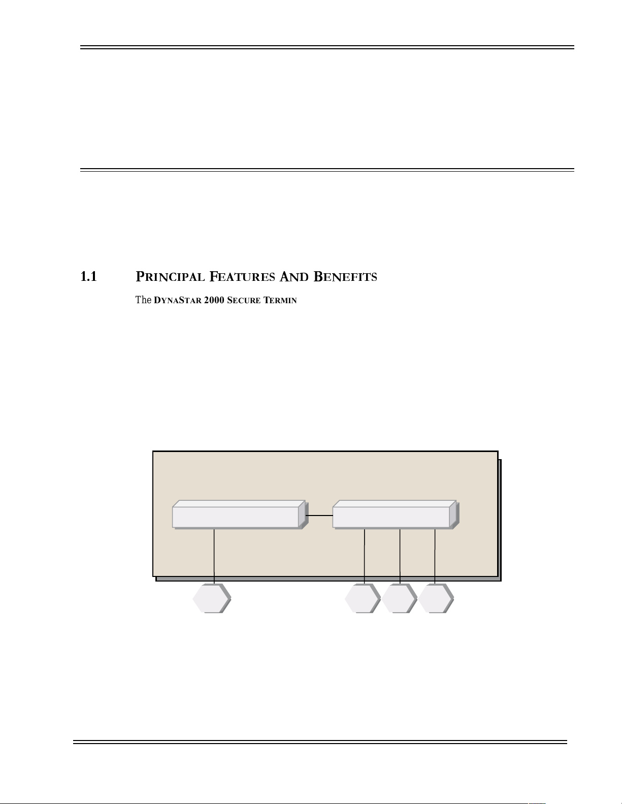
The DS2000-TS combines the c apabilities of an Async-to-TCP/IP Terminal Server and an IP Router in a
single inte grated device. This feature set, depicted in Figure 1-1, is used primarily in a Terminal Server
application as explained in the next section.
YNASTAR
RINCIPALFEATURESANDBENEFITS
2000 S
YNASTAR
ECURE TERMINAL SERVER
2000 S
ECURE TERMINAL SERVER
DynaStar 2000 Secure Terminal Server
is a purpose -bui lt networki ng pl atfor m for d istr ib uted
(DS2000-TS) is a multi-function, multi-protocol
Ethernet Router Terminal Server
Ethernet Connection Serial Devices
DS2000-TS Administrator’s Guide
S1 Sn
Figure 1-1. DS2000-TS Functional Integration
1 - 1
S2 E0
Page 16
C
HAPTER
Terminal Server Overview
D
1 -
YNASTAR
The DS2000-TS's device integration provides investment and operational savings compa red to alternative
solutions involving multiple less-integrated devices. Investment savings include both acquisition cost as
well as space allocation and engineering requirement s. Power system requirements are consolidated and
simplified, with the DS2000-TS supporting dir ect feeds from a wide range of DC power sour ces commonly
used at ind us trial s it es. Opera tio nal savings come from reduce d maintenance and administration , including
having fewer different software-based devices to coordinate for network configuration, diagnostics and
software upgrades.
2000 S
ECURE TERMINAL SERVER
Product Overview
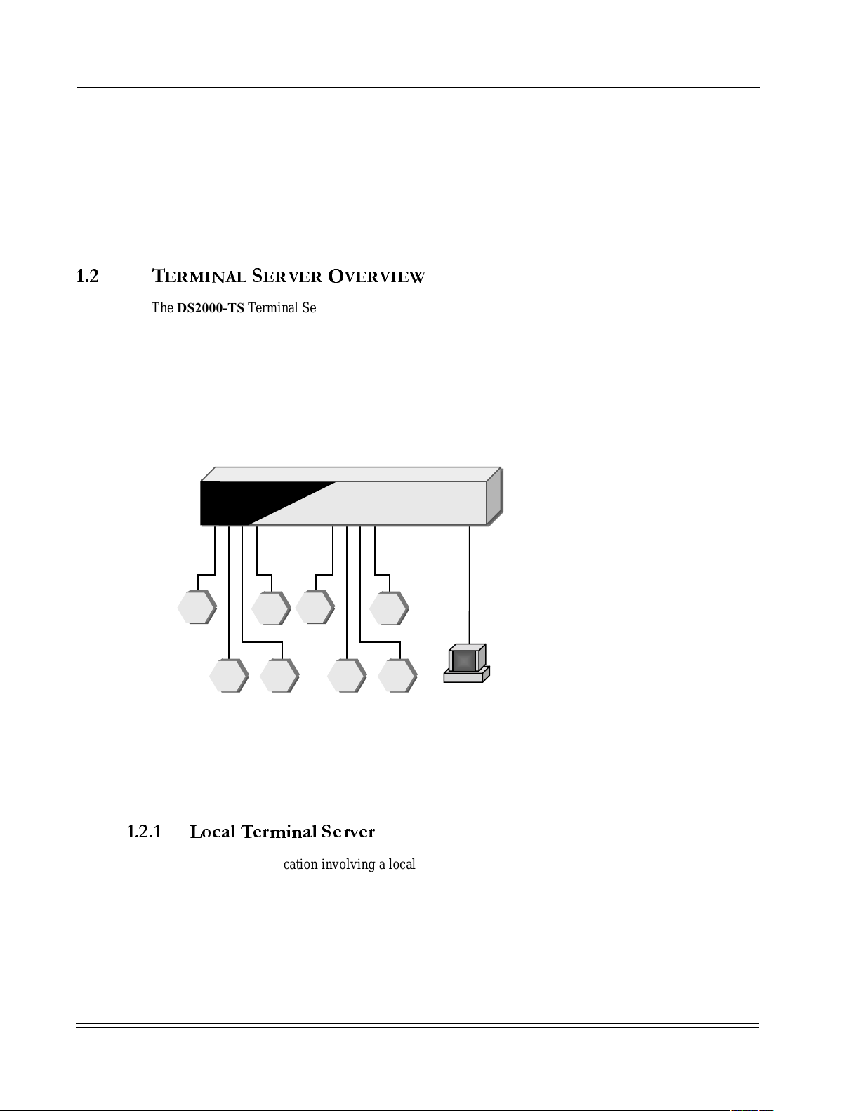
1.2 T
The DS2000-TS Terminal Server feature is typically used to enable a host-computer application based on
TCP/IP protocol to communicate with remote industrial devices that have an Async serial network interface
(see Figure 1-2). All communication is in IP-format from the central host to/from the remote site. The
DS2000-TS Terminal Server feature at the remote site disassembles each TCP/IP packet and provides an
Async seria l stream to the remo te device. In the reverse direction, Async responses from t he device are
assembled into TCP/IP packets, appropriate ly addressed and routed to the host application. More
specifically, all traffic on a DS2000-TS seria l interface is mappe d to /from an IP address and a s pecific TCP/
IP port or socket number.
ERMINALSERVEROVERVIEW
DynaStar 2000-TS
S1
S2
S3
S6 S5
S4
S8 S7
Serial Devices
Figure 1-2. Local Terminal Server
IP addr: x.x.x.x
Socket #s, e.g.: 10101,
10102, ...10132
TCP/IP
Ethernet Host
Application
There are se veral variations of the Terminal Server application, describ ed in the following para graphs.
1.2.1 Local Terminal Server
This is the typical application involving a local IP-host, i.e., a host collocated with the serial devices and
attached to a DS2000-TS port either directly or via a Local Area Network (LA N ) . The IP host may be a
distributed application server or a PC-based HMI device at the remote site.
DS2000-TS Administrator’s Guide
1 - 2
Page 17
C
HAPTER
1 -
D
YNASTAR
2000 S
ECURE TERMINAL SERVER
Product Overview
1.2.2 Reverse Terminal Server
This application has the same physical topology as the Local Terminal Server, but the communications
connection is initiated on-demand by the Serial device, rath er than by the host application. This requires
that th e DS2000-TS formulate a TCP/IP sess i on reques t to the host on behalf o f the serial device. In the
DS2000-TS, this is configured as an “Async-IP” terminal server connection, as differentiated from the more
common and default “IP-Async” terminal server connection.
1.2.3 Back-to-Back Terminal Server
This application uses two Terminal Server capabilities at both the host end an d async-device end of the
connection, providing serial interfaces to both the host system and remote device. The devices may be
attach ed to the same DS2000-TS or to different DS2000-TSs connected over a network. Back-to-Back
terminal server a llows end-to-end serial connections to be consolidated onto an al l IP -oriented network
infrastructure, keeping with the spirit of “IP Convergence,” at least at the transport layer of the network. In
this config uration , th e host end conne ction wou ld t ypical ly use an “Async-I P” con necti on ty pe, initi ating t he
TCP/IP session. T he other industrial device would be connected to a DS2000-TS using the default “IP-
Async” Terminal Server as described above.
The principal variant of Terminal Server used with the DS2000-TS is the Local Terminal Server.
Configuration guidelines for this service are provid ed in Chapter 3.
IP Routing
1.3 IP R
The DS2000-TS includes an integral IP router capability that enables a numbe r of applications and
enhancements to reliability and security.
IP Routing can be used locally within a site. Local routing is an alternative to layer-2 Ethernet switching
among Ethernet ports. IP routing provides communication among devices in different Ethernet VLANs and
can provide additional ne tw ork security using IP address filtering and IPsec encryption.
IP Routing is also us ed by the Terminal Server application described above. The Terminal Server feature
converts Async seria l communications to/from IP packet s. IP routing provides routing of these packets
either locally or rem otely.
The default mode for IP rout ing uses the RIP protocol to exch ange avail able rout e inf ormation wit h adjacent
routers. Advanced fe atures available with IP Routing include:
The Configuration Basics described in Chapter 3 d eal primarily with default IP routing using RIP,
suppor ting Terminal S er ver traffic. Other IP R outing feat ures a re described prim arily in the re f erence
sections of Appendix B.
OUTING
• IP address filtering (sel ective blocking of permitted sources a nd destinations)
• VPNs using IPsec with DES or 3DES enc ryption
Static routing (explicit next hops, not using a routing protocol like RIP)
•
DHCP client and server (automati c assignment of IP addresses)
•
DS2000-TS Administrator’s Guide
1 - 3
Page 18
C
HAPTER
DS2000-TS Management Features
1 -
D
YNASTAR
2000 S
ECURE TERMINAL SERVER
Product Overview
1.4 DS2000-TS M
This s ec tion pro v id es summa ri e s of selected managemen t capabilities for all DS2000-TS services.
1.4.1
1.4.2 LEDs and Alarms
1.4.3 SNMP and MIBs
1.4.4 Security
DynaStar Supervisor
Chapter 3 provides details on the DynaStar Supervisory application. This menu-based m anagement
application supports configuration, diagnostics, performance monitoring and security functions for the
DS2000-TS. The Supervisor is accessed over the local console port or remotely via an IP network.
The DS2000-TS has a number of visual alarm and status indicators implemented as LEDs on the wiring
panel of the dev ice. The re is als o an ala rm port th at pr ovides a hard con tact sta tus i ndicat ion of major s ystem
failure.
The DS2000-TS provides an SNMP MIB interface for status, statis tic s and provisioning. Alarms may be
formatted as SNMP traps to central network management systems.
ANAGEMENTFEATURES
A number of security options are available fo r management interfaces to the DS2000-TS. Mana gement
access securit y includ es both logi cal acce ss (e.g ., IP address filt ering, IPsec/VPN), and mul ti-le vel password
protections. Management data may be encrypted using IPsec with DES or 3DES.
1 - 4
DS2000-TS Administrator’s Guide
Page 19
+$37(5
UPERVISOR
This chapter provides an overview of the management application included in all DynaStars to
configure, administer, and troubleshoot the equipment and the network. The following sections
introduce the management application, describe access and login procedures, provide navigation
details and com mon commands, outline the menu hier archy, and provide an o verview of the sup erv i so r
capabilities.
This chapte r also describes a number of standard ta sks asso ciat ed with th e administration of the
D
YNASTAR
and not dependent on any particular configuration of the network or interfacing equipment.
2000 S
ECURE TERMINAL SERVER
in particular. These standard tasks are general in nature
2.1 S
The Supervisor a pplication running on the DS2000-TS manages the device. The Supervisor application is a
hierarchical menu-driven system allowing users to manag e and configure the DS2000-TS. Through the
super v is or ap p li cation, the user ca n co n f ig u r e po rt s, service s , an d fe at u r es; view sta t is t ic s ; c ar r y out
maintena nce activities and perf orm troubleshooting. The Supervis or application is accessible thr ough the
local console port or by using Telnet to connect to the DS2000-TS from the network.
2.2 U
This section describes the command notation used i n this manual and the methods for navig ation within the
Supervisor, along with how to select configuration settings, enter or modify data, and save changes.
2.2.1 Command Notation
This manual uses the following notations and conventions:
UPERVISOR
NIVERSALCOMMANDSFORSUPERVISORMENUNAVIGATION
The names of keys are bold and contained in angle brackets, for example <Enter>
•
Two keys pressed simultaneously appear in a n gle brackets separ ated by a hyphen (i.e.
•
<CTRL-D>)
Commands you must enter appear in italics
•
The names of menu fields also appear in boldface
•
Representative text in a command line appears in italics. For example, the word filename
•
indicates that an actual filename should replace the italicized word.
System messages appear in italics
•
DS2000-TS Administrator’s Guide
2 - 1
Page 20

C
HAPTER
Supervisor Overview
2 -
Universal Commands For Supervisor Menu Navigation
2.2.2 Navigation
To navigate down to a submenu:
• Type the command number and press <Enter>.
- or -
• Use the cursor keys (left, right, up and down arrows) to move to the desired function, and
press <Enter>.
To return to a previous menu:
• Press the <Esc> key.
- or In m enus with no modifiable field s, press ing the left arrow will display the previous menu.
•
To navigate within a modifiable menu:
Use the cursor keys to move ar ound the fields
•
Use the <Tab> key to send the cursor to the next modifiable field.
•
Press <Tab> repe at edly to get to the Pro cess selections field. Or , while in the leftmost field
•
of the screen, press t he lef t arrow ke y. This sends the curs or to th e bo ttom ri ght corner, which
is the Process selections field. The Process selections field appears on each screen where
there are modifiabl e parameters and is used to save the changes to volatile memory.
Although selecting Y and pressing <Enter> in the Process selections field saves the
changes, the user must also save the change s to F lash memory.
To change a modifiable field:
• To modify fields containing multiple toggle options, move the c ursor with the arrow keys or
<Tab> key until it is in the field to be modified. Pressing <Enter> toggles the parameter to
the next option. Pressing the <Enter> key repeatedly cycles through all the field options.
Moving out of the field temporar ily sets t he field to the value en tered. The change will
become permanent when the user saves the changes .
• To enter information in a text or number field, place the cursor in the field and type the
desired information. Moving the cursor out of the field stops editing the data field, and
temporar ily sets the field to t h e v alue entered. Th e change will become permanent w h en t h e
user saves the changes.
To edit input
The Supervisor Console is preconfigured to use the <Backspace> and <Delete> keys for
•
editing characters.
2.2.3 Saving Changes
Before a change can be saved to Flash memory it must first be processed. This adds the information to the
system from which the Flash memory is updated. The Process selections field is in the lower right corner of
all modifiabl e menus. To proc ess the changed configuration information, move the cursor to the Pro c ess
selections field. The Process selections field should contain a <Y> but if it is <N> type in the letter <Y> an d
press the <Enter> key. If the user does not wi s h to save the changes made, either press <Esc> to go back to
the previous m enu, or type <N> in the Process selections field and press <Enter>.
2 - 2
DS2000-TS Administrator’s Guide
Page 21
C
HAPTER
Accessing the DynaStar Supervisor
Once the informati on is processed, the system will display a reminder to save the changes to Flash memory
by this highlighted message : Config has changed: use <CTRL-W> to save. Pressing the <CTRL-W> saves
the system to Flash Memory. Once the save is complete, the message disappears and normal operation
resumes. If the system is re started by the Warm rest art method, or a power interruption, prior to saving the
changes to Flash memory, all unsaved change s will be lost.
Supervisor Overview
2 -
2.3 A
This section describes how to access and login to the DS2000-TS Supervisor application. The System
Operator Consol e is acces sed eithe r dire ctly fro m the consol e port on the DS2000-TS, or from a workst ation
on any connected IP device using Telnet, a ssuming that the DS2000-TS has a proper IP address assigned.
The user can manage m ultiple DS2000-TSs from a single workstation when using Telnet. All mode s of
access provide Password-based security.
2.3.1 Accessing the System Operator Console
For dir ect termi na l mode access to the console port:
For access via an IP network:
If you are connecting from a LAN, the Telnet connection screen, shown in Figure 2-1, appears before the
Login screen. Select <1> and press <Enter> for access to the Login screen. Upon direct connection via the
Console port, the Login screen displays the supervisory herald, the software version number, and a prompt
for a password as shown in Figure 2-2. You receive a prompt for the Supe rvisor’s password.
DynaStar_26 services
CCESSING THEDYNASTARSUPERVISOR
The required console terminal device is 9600 Baud, 7 bits, even parity, and 1 stop bit.
•
Telnet to the DS2000-TS's IP addre ss from a Telnet client (on standard port 23).
•
1 Console
2 Virtual Async Port
Enter service selection:
DS2000-TS Administrator’s Guide
Figure 2- 1. Telnet Screen
2 - 3
Page 22
C
HAPTER
Accessing the DynaStar Supervisor
Supervisor Overview
2 -
DynaStar Supervisor
DynaStar 2000
Software Version number 7.2 (RC38)
Copyright (C) 1990-2005 Dymec, Inc. All rights reserved.
Press ESC to exit, Ctrl-W for Wyse Terminal
To return to Supervisor, type 9999 <RET>
Enter Password:
Figure 2-2. Login Screen
NOTE: If the DS2000-TS was already booted before the console device was connected, you
&
&
&&
2.3.2
may see a simple “*“ prompt and not the supervisory herald as shown above. This indicates
that the logon screen timed out, terminating the active session and switching to a pure
listening mode. Type “9999" to display the logon/supervisory herald as shown in
Figure 2-2.
Logging In
At the Enter Password prompt, type the password and press <Enter>. The password is case sensitive. The
factory default password is “secret” and a first-time login requires using the default login pass word. Type
secret and press <Enter>. If a valid password is not received in three attempts, the connection to the
Supervisor clears, and the message CLR PAD is displayed. To reconnect to the Supervisor, type in “9999”
and press <Enter>. Check the Cap s Lock setting if a password fails unexpectedly.
Instructio ns for changing the default password and establi shing multiple user levels and differ ent passwords
for each level are provided in Appendix D, “Security Commands”.
2 - 4
DS2000-TS Administrator’s Guide
Page 23

C
HAPTER
Supervisor Overview
2 -
Supervisor Menus
2.4 S
UPERVISORMENUS
The Main Menu, shown in Figure 2-3, shows the four main branches of the Supervisor command hiera rchy.
The submenus in these four main areas of the Supervisor provide a full set of menu-driven commands.
The four subsections shown in the Main menu are:
• Port
• Network
• System
• Security
*** Main Menu ***
1 - Port Configuration, statistics, activation, monitoring
2 - Network TCP/IP, Bridge, Terminal Server and Frame Relay
3 - System Event log, buffer status, restart, SNMP, clock set
4 - Security Passwords, menu access and security options
__________[DynaStar_24]___________
Terminate input with <RET> Press ESC to return to previous menu
Enter command number:
Figure 2-3. Main Menu
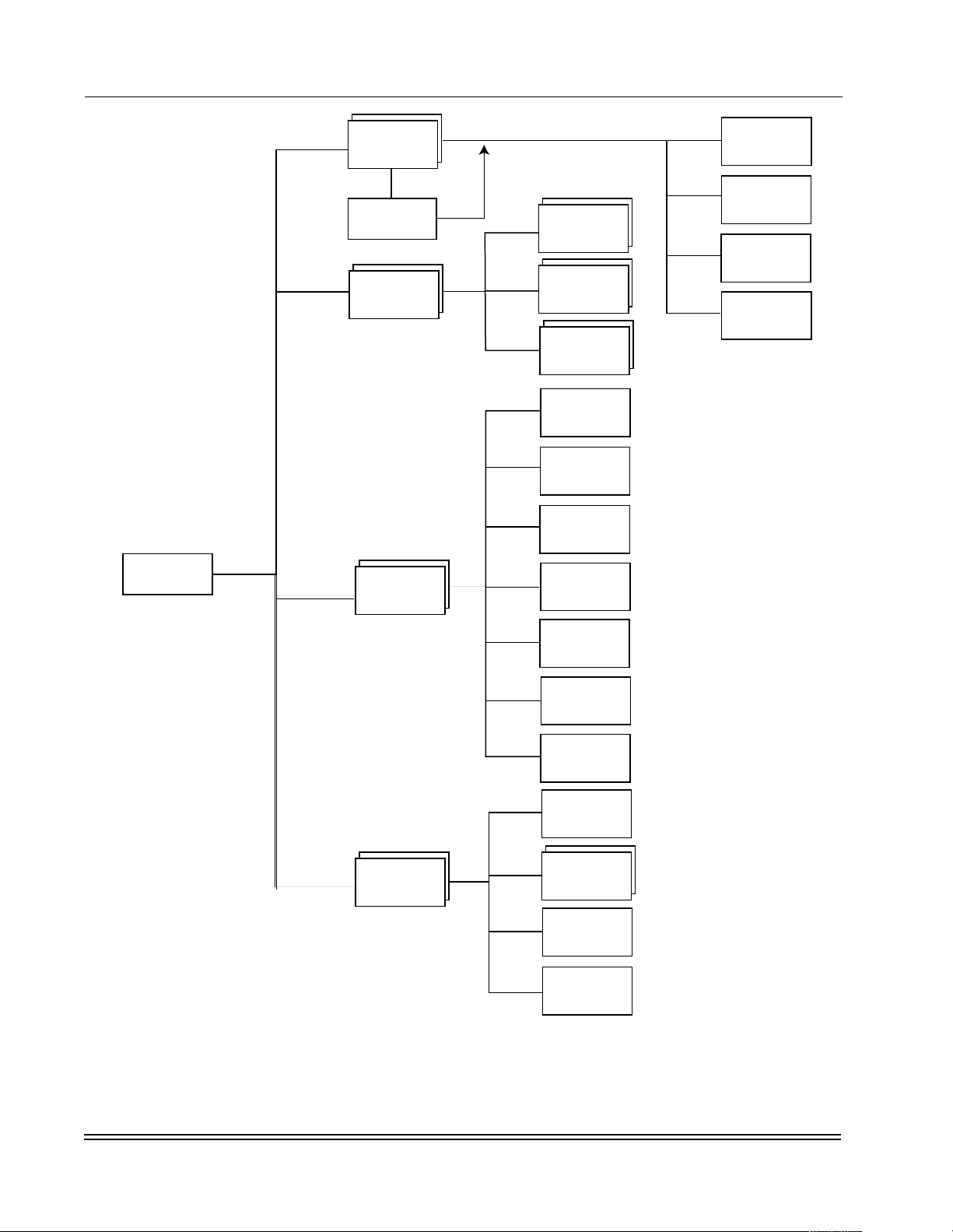
An overview of the Supervisor application menu structure is shown in Figure 2-4. The menu structure is
divided into four se ctions: Port, Network, System and Security. The figure gives only the top level view of
the menu structure. The following subsections provide high-level descriptions of the structure and uses for
each of these four subsections. The Appendices provide an in-depth reference for each of the Main m enu
comman d areas.
DS2000-TS Administrator’s Guide
2 - 5
Page 24
C
HAPTER
2 -
Supervisor Menus
Supervisor Overview
MAIN MENU
<1>
<2>
<3>
Port
<Enter>
Port Status
Network
System
<1>
<2>
<3>
<1>
<2>
<3>
<4>
Router
Terminal
Server
Async
Services
Code Versions
Restart
Event Log
Buffer Usage
<1>
<2>
<3>
<4>
Configuration
Statistics
Disable/
Enable
Protocol
Monitor
System
<5>
Parameters
<6>
Date & Time
<4>
Security
<7>
<1>
<2>
<4>
<3>
SNMP
Password
Change
Access
Security
Security
Options
Console
Monitor
Figure 2-4. Supervisor Menu Hierarchy Overview
2 - 6
DS2000-TS Administrator’s Guide
Page 25

C
HAPTER
Supervisor Overview
2 -
Supervisor Menus
2.4.1 Port Menus
Selecting <1> Port on the Main menu takes you to the Port Selection menu where the user selects a port to
configure, enable/disable, view statistics, or display the current data being transferred (using the built-in
Protocol Monitor). The Port Menu (Figure 2-5) displays a list of the DS2000-TS ports listing the port
number and port name al ong with a prompt a sking the user t o spec if y a port. Entering a port number presents
the user with the Port Function menu (Figure 2-7) showing the functions that are available on t hat port.
*** Port Menu ***
Port Name
E0 Ethernet S13 SERIAL-S13 S29 SERIAL-S29
S0 Sync/Async S14 SERIAL-S14 S30 SERIAL-S30
CON Console S15 SERIAL-S15 S31 SERIAL-S31
10 Virtual PAD S16 SERIAL-S16 S32 SERIAL-S32
S1 SERIAL-S1 S17 SERIAL-S17
S2 SERIAL-S2 S18 SERIAL-S18
S3 SERIAL-S3 S19 SERIAL-S19
S4 SERIAL-S4 S20 SERIAL-S20
S5 SERIAL-S5 S21 SERIAL-S21
S6 SERIAL-S6 S22 SERIAL-S22
S7 SERIAL-S7 S23 SERIAL-S23
S8 SERIAL-S8 S24 SERIAL-S24
S9 SERIAL-S9 S25 SERIAL-S25
S10 SERIAL-S10 S26 SERIAL-S26
S11 SERIAL-S11 S27 SERIAL-S27
S12 SERIAL-S12 S28 SERIAL-S28 Enter Port Number:
_________[DynaStar_6b2c]__________
Press ESC to return to previous menu Press <RET> for port status
Figure 2-5. Port Menu
There is an advanced menu selection accessible from the Port Menu called the Port Status menu, and
shown in Figure 2-6. The advanced menu shows the current status of all ports and is reached by pressing
<Enter> while in the Port Menu. From the Port Status menu, the user may either select the port number to
jump to the Port Function screen or press <Esc> to exit to the Port Selection menu.
DS2000-TS Administrator’s Guide
2 - 7
Page 26

C
HAPTER
2 -
Supervisor Menus
*** Port Status ***
DynaStar 2000 12-11-05 7:33:55
Ethernet SLOT 1 SLOT 2
Port number: E0 S1 - S16 S17 - S32
Name: Ethernet MUSART MUSART
Interface: IS-Enet
Protocol: Ethernet
State: Enabled
Status: Link Down
Sync/Async HS WAN 1 HS WAN 2 Console
Port number: S0 CON
Name: Sync/Async No board No board Console
Interface: RS-232 RS-232
Protocol: PAD Console
State: Enabled Enabled
Status: Down Up - 1
Enter slot # to view status of multiple-port module:
_________[DynaStar_6b2c]__________ Enter Port Number:
Press ESC to return to previous menu
Supervisor Overview
Figure 2-6. Port Status Menu
Selecting a port from either the Port Selection menu or the Port Status menu, displays the Port Functions
menu as shown in Figure 2-7. From the Port Functions menu the user can select to:
• Configure the port
• Obtain Statistics on the port
• Disable or Enable the por t
• Use the Protocol monitor to view the traffic being passed o n the port
Appendix A, “P ort Functions” in the rear of this manual provides details on the Port related menus.
*** Functions For Port S1 ***
1 - Configuration Configure protocol and port parameters
2 - Statistics Display port statistics
3 - Disable/Enable Disable, enable, initialize or busy
4 - Protocol Monitor Display transmitted/received data packets
Enter command number:
_________[DynaStar_6b2c]__________
Terminate input with <RET> Press ESC to return to previous menu
Figure 2-7. Port Functions Menu
DS2000-TS Administrator’s Guide
2 - 8
Page 27

C
HAPTER
Supervisor Overview
2 -
Supervisor Menus
2.4.2 Network Menus
The Network menu and it s sub menus provi de the means t o conf igur e and ch eck the lo ca l area network s etup
(e.g., IP Router and Ethernet switch). Selecting the <2> Network submenu from the Main menu displays
the Networking Setup and Status menu shown in Figure 2-8.
*** Networking Setup and Status ***
1 - Router Configure and display router options
2 - Terminal Server Configure Async-TCP/IP terminal server
3 - Async Services Configure Async options
Enter command number:
_________[DynaStar_6b2c]__________
Terminate input with <RET> Press ESC to return to previous menu
Figure 2-8.Networking Setup and Status Menu
Through these setup and status menu items, the user can configure the system Router, Terminal Server, and
Async settings for all of the ports and connections to the DS2000-TS. The conf iguration options include:
• Router - Setup and Status
• IP port configuration
• IP Routes and display
• IP static route setu p
• IP filters
• TCP/IP status
• OSPF (Open Shortest Path First) (not opera tional in the DS2000-TS)
• DHCP (Dynamic Host Configuration Protocol)
• VPN (Virtual Private Network)
• VRRP (Virtual Router Redundancy Protocol) (not operational in the DS2000-TS
• TCP Multicast
• Terminal Server - Configuration
• Async - Services
• PAD ( Packet Assembler Disassembler) profile settings
• Logon screen settings
A complete re ference for the Networking Setup and Status menus is in Appendix B, “Network Commands ”.
2.4.3 System Menus
Selecting option <3> Systems from the Main menu displays the System Functions sub-menu shown in
Figure 2-9. Within these submenus, the user can:
DS2000-TS Administrator’s Guide
2 - 9
Page 28

C
HAPTER
2 -
Supervisor Menus
Selecting <1> Code Versions from the Systems Funct ions menu shows the file structure held in memory,
including the configuration files. This also allows the user to delete files from memory. The file system can
hold multipl e copie s of t he Operating Syst em in th e Flash memory. The operator can delete unwante d cop ies
of the file system and free up space by enabling defragmentation of the file system.
Selecting <2> Restart from the Systems Functions menu allows the Administrator to restart the system
using a Warm restar t, Co ld re sta rt, or Reini ti aliz e (Re ini tial iz e wil l on ly appe ar i f the re is a cnfgload.cmp file
present ) . All o p t io n s wi l l r eb o ot t he sys tem an d r es t art a ctive operations; however, they differ in the source
used for the operating software and active configuration file during, and after, the restart operation.
Selecting <3> Event Log from the Systems Functions menu displays the event log for the DS2000-TS. The
event log contains status, information, and error messages with date and time stamp.
Selecting <4> Buffer Usage from the Systems Functions menu displays the Buffer Pool Status screen
containing information on the installed memory and the current buffer utilization.
Supervisor Overview
Vie w the current versions of software running and stored on the DS2000-TS
•
Restart the system with WARM and COLD start commands
•
Vie w the event log
•
Check the buffe r usage
•
Set a unique system name and screen herald
•
Configure the system clock and time
•
• Setup the SNMP pa rameters.
Selecting <5> System Parameters from the Systems Functions menu brings up a screen where the user can
set the Serv er name and Supervisor console herald.
Selecting <6> Date & Time from the Systems Functions menu to modify the on-boa rd Real Time Clock.
The time an d date are initially preset. The Real Time Clock is ba t t ery backed up so this adjustment only
needs periodic adjustments to compensate for leap years, etc.
Selecting <7> SNMP from the Systems Functions menu gives the user acces s to SNMP information and
settings including system information, read/write community strings, and SNMP trap addresses.
For a detailed description of the Supe rvisor System level hierarchy refer to Appendix C, “System
Functions”.
2 - 10
DS2000-TS Administrator’s Guide
Page 29
C
HAPTER
*** System Functions ***
1 - Code Versions Display downloaded software versions
2 - Restart Restart or initialize system
3 - Event Log Display system event log
4 - Buffer Usage Display system buffer usage
5 - System Parameters Configure system-wide parameters
6 - Date & Time Set the system date and time
7 - SNMP Configure community strings, trap IP addresses
Supervisor Overview
2 -
Supervisor Menus
__________[DynaStar_24]___________
Terminate input with <RET> Press ESC to return to previous menu
Enter command number:
Figure 2-9. System Functions Menu
2.4.4 Security Menus
The Supervisor Security menu al lows the Admini strator (Roo t) to set va rious le vels of security. The security
is assigned based on the user (operator) and also by setting access levels to functions. Selecting <4>
Security from the Main Menu accesses the Security Functions menu shown in Figure 2-10.
In addition to the standard root access, the DS2000-TS supports access for up to five additional operators.
The root user defines the names and access authorizations of these operators. Three levels of access are
configurable : No Access (N), Read -Only Acce ss (R), and W rit e Access (W). No Access , bloc ks the operator
from accessing a given group of commands. Read-Only Access, allows the operator to view parameters, but
not change them. Write Access, provides the ability to read and modify parameters. The root user has Write
Access to all commands. By default, the operator settings a r e No Acce s s fo r al l g roups of commands. There
are no default pa sswords for the five operators. The root user must configure these passwords, and it is also
recommended that a new root user password be assigned once the DS2000-TS is installed.
DS2000-TS Administrator’s Guide
2 - 11
Page 30

C
HAPTER
2 -
Supervisor Menus
*** Security Functions ***
1 - Password Change Set console user names & passwords
2 - Access Security Set operator menu access permissions
3 - Security Options Set validation options and methods
4 - Console Monitor Display or configure console monitor log
Enter command number:
_________[DynaStar_6b2c]__________
Terminate input with <RET> Press ESC to return to previous menu
Supervisor Overview
Figure 2-10. Security Functions Menu
To change the password of the root user or operat ors, Select <1> Password Change from the Security
Functions menu.
T o set the access security parameters for the various system login accounts (user/operators), select <2>
Access Security from the Security Functions menu. The Access Control m enu for the de signa ted operato rs
appears. T here are three types of securi ty at the s ystem level implemented on the DS2000-TS. These give
access by function and also by user password.
By selecting <3> Security Options from the Security menu the administrator can enable Enforce Secure
passwords. By selecting this method the system prompts for a user name as well as the use of minimum
length password and to use a mix of alpha and numeric characters, when new passwords are entered. To
enable the Enforce Se cure password policy, select <3> Security Options from the Security menu.
<4> Console Monitor displa ys the monitor log and lets the operator configure which events are monitored.
CAUTION: If the root password is lost the user must contact Dymec customer support. For
contact instructions refer to “Contacting Dymec” on pagevi.
Refer to Appendix D, “Security Commands” for details on setting other security options.
2 - 12
DS2000-TS Administrator’s Guide
Page 31

+$37(5
This chapter provides basic configuration guidelines for the D
S
ERVER
chapter illustrates how to configure a basic Terminal Server application. It is assumed that the physical
network connections have been made to the DS2000-TS, that the ne twork designs are comple te, and
that all configuration data ar e available.
3.1 T
The Terminal Server feature allows for TCP/IP applications to interact with Async serial-based devices over
an IP-based network. Asynchronous data stre ams are packetized into TCP/IP formatted frames using
traditional terminal server functions. The frame is then routed over an IP network.
To configure the DS2000-TS to act as a terminal server, the user must do the following:
YNASTAR
. The DS2000-TS c an be configured for Terminal Server and IP routing applications. This
2000 S
ECURE TERMINAL
ERMINALSERVERCONFIGURATIONEXAMPLE
Configure the Router features
•
Enter the IP address for the Ethernet port (example in Figure 3-1, 192.168.1.1)
•
Select the discovery protocol being used
•
Configure the serial ports
•
Assign a port name
•
Assign loca l socke t num ber
•
Set line speed and parity
•
Assign DSS usage
•
Assign the proper profile
•
Figure 3-1 shows a very basic network. The following procedure describes how to configure the
DS2000-TS on the r ight, i.e. a typi cal remote site. The configuration allows the IP-based host system on the
left, labeled B, to send and receive data from all serial devices configured on the DS2000-TS, labeled A.
Refer to this figure during the configuration to understand the connection process. The procedures use the
configuratio n dat a from t he figure be low. Note that the Rou ter at location B (whi ch can al so be a D
2000) also requires configuration to complete the end-to-end network path.
DS2000-TS Administrator’s G uide
3 - 1
YNASTAR
Page 32

C
HAPTER
Configuration Basics
3 -
Terminal Server Configuration Example
B
192.168.10.1
255.255.255.0
Ethernet
192.168.10.2
255.255.255.0
Management
Device
DynaStar
Serial
Socket 10201
192.168.1.2
255.255.255.0
Ethernet LAN
A
DynaStar 2000-TS
Port E1
192.168.1.1
255.255.255.0
Serial
Socket 10202 (S2)
Socket 10201 (S1)
Figure 3-1. Terminal Server Configuration Example
3.1.1
Assigning an IP Address to the System for TerminalServer Functionality
In this section the use r wi ll configure the IP port information for the Router and the se rial port. This section
configures IP information for the local DS2000-TS.
1. From the Main menu select <2> Network, <1> Router. The Router Setup and Status menu
appears, as shown in Figure 3-2.
*** Router Setup and Status ***
1 - IP Port Configuration Configure port IP addresses
2 - IP Routes Display Display IP routing table contents
3 - IP Static Routes Configure static IP routes
4 - IP Filters Configure IP address filters
5 - TCP/IP Status Display TCP connection status
6 - OSPF Configuration Configure OSPF
7 - DHCP Configure and display DHCP
8 - VPN Configure and display VPNs
9 - VRRP Configure and display VRRP groups
10 - TCP Multicast Configure and display TCP Multicast groups
Enter command number:
_________[DynaStar_6b2c]__________
Terminate input with <RET> Press ESC to return to previous menu
Figure 3-2. Router Setup And Status Menu
3 - 2
DS2000-TS Administrator’s Guide
Page 33

C
HAPTER
Configuration B asics
3 -
Terminal Server Configuration Example
For basic applications of the DS2000-TS, the only IP-related functions that require configuration are the
local IP address and sometimes the version of routing protocol to be used. A number of advanced IP options
are also supported. For descriptions and instructions concerning these advanced options, refer to “Router
(IP)” on page B-4.
2. In the Router Commands menu sele ct <1> IP Port Configuration. The IP Port Information menu
appears, see Figure 3-3.
*** IP Port Information ***
Last changed: 12-11-05 6:10:53
Port(s) Interface IP Address IP Mask |-Use RET to toggle|
x.x.x.x x.x.x.x Protocol Encaps
E0 Ethernet 192.168.1.1 255.255.255.0 RIP II Enet II
_________[DynaStar_6b2c]__________ Process IP Addresses (Y/N): Y
Lines with port ranges are multiport interfaces. Configure these ports together
on one line. Or with cursor on line, press <CTRL-O> to configure separately.
*Fields are blank on this screen if ports are configured separately.
Figure 3-3 . IP Port Information Menu
3. On the first line, ente r the IP address to be associated with the local DS2000-TS in the IP Address
field. A default subnet mask will be filled in automa tically. Make changes to the default mask as
needed.
4. Select the discover y protocol to be used , based on the network us age. Options are RIP (defaul t ),
RIP II, NONE, and RIP RX.
5. With the cursor at the bottom of the menu with a Y in the Process IP Addresses field, press the
<Enter> key.
6. Save changes to flas h by pressing <CTRL-W>.
3.1.2 Configure the Serial Ports for Terminal Server
In this s ection the user will c on figure the serial p o r ts in th e Terminal Server Configuration menu.
1. The path to the Terminal Server m enu is Main menu, <2> Network, <3> Terminal Server. The
Terminal Server Configuration menu, shown in Figure 3-4, is displayed.
DS2000-TS Administrator’s G uide
3 - 3
Page 34

C
HAPTER
Configuration Basics
3 -
Terminal Server Configuration Example
*** Terminal Server Configuration ***
Last changed: 0-0-90 0:00:00
Port Name Type Local Tel Async Parity DSS Profile
(14) (Fixed) Socket Raw Speed Ignore
S0 Sync/Async IP-ASY 10003 N 9600 Baud 7-EVEN N 89(14) CRT
S1 SERIAL-S1 IP-ASY 10101 N 9600 Baud 7-EVEN N 89(14) CRT
S2 SERIAL-S2 IP-ASY 10102 N 9600 Baud 7-EVEN N 89(14) CRT
S3 SERIAL-S3 IP-ASY 10103 N 9600 Baud 7-EVEN N 89(14) CRT
S4 SERIAL-S4 IP-ASY 10104 N 9600 Baud 7-EVEN N 89(14) CRT
S5 SERIAL-S5 IP-ASY 10105 N 9600 Baud 7-EVEN N 89(14) CRT
S6 SERIAL-S6 IP-ASY 10106 N 9600 Baud 7-EVEN N 89(14) CRT
S7 SERIAL-S7 IP-ASY 10107 N 9600 Baud 7-EVEN N 89(14) CRT
S8 SERIAL-S8 IP-ASY 10108 N 9600 Baud 7-EVEN N 89(14) CRT
S9 SERIAL-S9 IP-ASY 10109 N 9600 Baud 7-EVEN N 89(14) CRT
S10 SERIAL-S10 IP-ASY 10110 N 9600 Baud 7-EVEN N 89(14) CRT
S11 SERIAL-S11 IP-ASY 10111 N 9600 Baud 7-EVEN N 89(14) CRT
S12 SERIAL-S12 IP-ASY 10112 N 9600 Baud 7-EVEN N 89(14) CRT
S13 SERIAL-S13 IP-ASY 10113 N 9600 Baud 7-EVEN N 89(14) CRT
S14 SERIAL-S14 IP-ASY 10114 N 9600 Baud 7-EVEN N 89(14) CRT
_________[DynaStar_6b2c]__________ Process selections (Y/N): Y
<RET> to toggle or type value Press ESC to return to previous menu
Cursor up/down for more entries Press <CTRL-O> for more options
Use <CTRL-D> to delete entry
Figure 3-4. Terminal Server Configuration Menu
2. In the Terminal Server Configuration menu set the following parame t ers for ea ch serial port to be
configured for Terminal Server operation:
• Name - The default name for this port can be change d. Enter a new name as de sired,
maximum length is 14 characters
• Local Socket - the default socket number assigned is 10100 + the port number. Move to this
field and type in a new value if required.
• Tel Raw - N disables all Telnet negotiation parameters on the IP side of the connection
• Async Sp eed used by t he serial device connected to the seria l port of the DS2000-TS.
Toggle the values by pressing the enter key.
• Parity - default 7-Even, toggle the values by pressing the enter key
• DSS Ignore - toggle to Y if the device connected to this port does not supply data set signals
(DCD).
• Typically, in the Profile field type in 85, which is preconfigured as a SCADA profile, and
press <Enter>. To define or use other profiles refer to section “PAD Profiles” on page B-2 6.
3. While in the Terminal Server Configuration menu press <CTRL-O>. The Advanced Terminal
Server Configuration menu will be shown, as seen in Figure 3-5.
3 - 4
DS2000-TS Administrator’s Guide
Page 35

C
HAPTER
Configuration B asics
3 -
Terminal Server Configuration Example
*** Advanced Terminal Server Configuration ***
Last changed: 0-0-90 0:00:00
Port Name Type Local Remote Remote FR (Fixed) VRRP
(14) Socket Socket IP Address Port DLCI V.R.ID
S0 Sync/Async IP-ASY 10003
S1 SERIAL-S1 ASY-IP 10101 0.0.0.0
S2 SERIAL-S2 ASY-IP 10102 0.0.0.0
S3 SERIAL-S3 IP-ASY 10103
S4 SERIAL-S4 IP-ASY 10104
S5 SERIAL-S5 IP-ASY 10105
S6 SERIAL-S6 IP-ASY 10106
S7 SERIAL-S7 IP-ASY 10107
S8 SERIAL-S8 IP-ASY 10108
S9 SERIAL-S9 IP-ASY 10109
S10 SERIAL-S10 IP-ASY 10110
S11 SERIAL-S11 IP-ASY 10111
S12 SERIAL-S12 IP-ASY 10112
S13 SERIAL-S13 IP-ASY 10113
S14 SERIAL-S14 IP-ASY 10114
_________[DynaStar_6b2c]__________ Process selections (Y/N): Y
<RET> to toggle or type value Press ESC to return to previous menu
Cursor up/down for more entries Use <CTRL-D> to delete entry
Figure 3-5. Advanced Terminal Server Configuration Menu
4. If using the revers e terminal server feature, toggle the IP-ASY field which will then display ASY-
IP and the Rem ote Socket and Remote IP Address fields will also need to be completed.
5. Repeat the previous step for all othe r serial ports to be configured for T erminal Server.
6. Cursor down to the Process selections field, ensure that a Y is displayed in th e field and press
<Enter>.
7. Save changes to Flash by pr essing <CTRL-W>.
DS2000-TS Administrator’s G uide
3 - 5
Page 36

C
HAPTER
Terminal Server Configuration Example
Configuration Basics
3 -
3 - 6
DS2000-TS Administrator’s Guide
Page 37

+$37(5
This chapter provides ideas and suggestions for troubleshooting and maintaining the DS2000-TS by
using featu r es in the Supe rvisor applic ati on. This inf orm ation is only a gui de for spec ific s ituat ion s. The
troubleshooting suggestions make reference to the Appendices that provide detailed scree n and
parameter information. The Software Maintenance section of this chapter is concerned with software
maintenance and the creation of software backups and loading new code versions.
4.1 T
The Supervisor application allows you to troubleshoot the DS2000-TS and determine the current status at
each of the following levels:
The user/operator can go into each of the listed areas to troubleshoot or verify proper operation. The
following sections discuss the above menu item s and give m enu path information to reach them, along with
cross-references to descriptions.
4.1.1 Port
The user can examine the Ports on the DS2000-TS to determine the current status, s ta tistic al details, and
monitor live traffic.
The Port Status menu provides th e current s tatus of port s on the DS2000-TS. This data is c urr en t a t th e t ime
the menu is loaded and shows at a glance the status of all of the ports. To reach the Port Status menu press
<1> Port in the Main Menu and then press <Enter> from the Port Menu that is displaye d to display the
Port Status menu. Thi s scre en provides the user with the Port number, name, type of connection, current
availability, and current operating status. The Port Status menu is shown in Figure A-3 on page A-3. To
check for changes press <Enter>, whi ch will refresh and updat e th e screen, or wait for the automat ic sixty-
second upda te.
ROUBLESHOOTING
Port
•
Network
•
System Level - Buffer Usage
•
Event Log
•
4.1.1.1 Port Status
DS2000-TS Administrator’s G uide
4 - 1
Page 38

C
HAPTER
Troubleshooting
4 -
Troubleshooting and Software Maintenance
4.1.1.2 Port Statistics
The Port Statistics menus provide a host of information for troubleshooting most port-based problems. The
informatio n on th is screen s hows the curre nt status of the port (Up or Down), Tx and Rx rates, error counts,
details on tr an smissions, an d a c omplete list of port -related data. To reach the Port Statistics menu, press
<1> Port in the Main Menu, and enter the port number: E0, CON for Console or S1 - S32 for Serial
(Async) ports, followed by <Enter>. Then press <2> Statistics. This screen displays statistics specific to
the type of port selected.
The following list e xplains where in this manual to find figures and tables describing statistics for each port
type.
• Console -Figure A-12 on page A-16, TableA-8 on pageA-16
• Serial (Async) - Figure A-11 on page A-14, Table A-7 on pag eA-14
4.1.1.3 Port Protocol Monitor
The Pro to col Moni tor shows the current data bein g transmit ted and received on any selected port to assist
you in determining the location of a fault somewhere in the network. To reach the Protocol Monitor Menu,
press, <1> Port in the Main Menu to enter the Port Menu. Next enter the port number to view (E0, CON
for Console or S1 - S32 for Serial), and press <Enter>. Then press <4> Protocol Monitor. More detail on
the Protocol monitor appears in ”Protocol Monitoring” on page A-19.
4.1.2 Network
Using Network menus in conjunction with Port statistics and status helps determine if the Routing and IP
connections are operatin g as configured. The IP Addresses and TCP/IP Status menus displ ay the ARP table,
routing table , and the connec tion s tatus of all IP-ba sed c onnect ions t o the DS2000-TS. To reac h the se m enu s
press <2> Network from the Main Menu, then <1> Router, followed by either <2> IP Routes Display or
<5> TCP/IP Status. The IP Addresses menu is shown in Figure B-5 on page B-6 and the TCP Connection
Status screen is shown in Figure B-9 on page B-10.
4.1.3 Buffer Usage
The Buffer Usage menu informs you of a possible DS2000-TS buffer resource overload due to line,
transmission, or protocol problems. Climbing In Use counts with declining Free buffer counts could be an
indication of a problem. To reach the Buffer Pool Status menu, enter <3> System from the Main Menu,
and then <4> Buffer Usage. Figure C-6 on page C-6 shows the Buffer Pool Status menu.
4 - 2
DS2000-TS Administrator’s Guide
Page 39

C
HAPTER
Troubleshooting and Software Maintenance
4 -
Boot Process
4.2 B
The onboard ROM is the source of the BOOT process; this ROM is based o n a copy of the full operating
system and is normally fixed for the lifetime of the product. With a console port connected, the BOOT
process resembles information contained in Figure 4-1.
OOTPROCESS
DYMEC, Inc.
Flash 0 is 4MB AMD top boot [ID = 01f6]
DS1500 ROM version 7.1 (RC47)
Serial number b441334
Ethernet address 00206100c1f6
*** Press ESC to boot download immediately ***
*** Press CR to enter LAN monitoring mode ***
Test 8MB RAM addresses
Test 8MB RAM pattern
Monitoring LAN for ROM commands
Get IP address from SRAM copy #1 of 2
Current IP address is 0.0.0.0
Enter different IP address:
Loading DOWNLOAD.BIN
Decompressing 7.1 (RC47)... Done!
#portVars=182, #link=150, #pad=20, #packet=151
Using SRAM #1, length = 369882, (181 ports)
******* Error Log *******
2005-02-11 16:44:39 System reset (may be power up or deliberate restart)
2005-02-12 11:45:08 System reset (may be power up or deliberate restart)
2005-02-13 17:14:23 System reset (may be power up or deliberate restart)
2005-02-14 8:06:12 System reset (may be power up or deliberate restart)
******* Error Log End *******
Figure 4-1. BOOT Process Example
After initia ting the boot process, the system temporarily halts for 20 seconds. The reason for pausing is to
provide the ability to configure the DS2000-TS if no runtime operating system has been loade d. In
particular, the pause provides an opportunity to set an initial IP address for downloading software and
establishi ng Telnet command sessions. If an op erati ng system already exists , then pre ssing <Esc> before the
end of the 20-s econd pause will resume the boot process. If no key is pressed and 20 seconds elapses, the
system will boot automatically.
This com pletes the boot process and the screen will display the opening banner and login menu. The current
contents of the event log are the last part of the boot process and can be useful in diagnosing boot problems
in the unli kely event t he system fails to boot.
DS2000-TS Administrator’s G uide
4 - 3
Page 40

C
HAPTER
Initializing an IP Address
Troubleshooting and Software Maintenance
4 -
4.3 I
NITIALIZING AN
If an ope rating sy stem doe s not already exist, then you must establish the “Local/ROM Address” during the
Boot process. The “Local/ROM Address” requires an IP address assigned to it in order to rem otely
download software to the Super visor and/or permit SNMP communica tions with the DS2000-TS. If the
system is already running under an operating system, assignment of the Local/ROM Addre s s is th rough the
console command menus. (Refer to ”Assign IP Addresses And Protocols” on page B-5.) If no operating
system exists on the DS2000-TS, execute the Boot process as de scribed in ”Boot Process” on page 4-3. The
Boot process will pause for 20 seconds right after the following message appears:
Current IP address is 0.0.0.0
During this time, the Console displays a prompt to enter an IP address. The IP assignment allows IP
applications like TFTP and Telnet to communicate with the DS2000-TS from a remote location in order to
make configur ati on changes and/or upgrade the Operating System to a newer version.
Enter different IP address:
The IP address can be entered in a normal IP address format e.g. 100.1.1.1 <Enter>. The system displays a
prompt with the IP addres s just ent ere d.
100.1.1.1 <Enter>
Enter different IP address:
The system has accepte d the IP address entered but not fully proce ssed it at this point . The IP address can be
changed by typing in another IP address or, if the address displayed is acceptable, just press <Enter> to
commit this address to Flash and complete the install process.
IP A
DDRESS
4 - 4
DS2000-TS Administrator’s Guide
Page 41

C
HAPTER
Troubleshooting and Software Maintenance
4 -
Software Maintenance
4.4 S
OFTWAREMAINTENANCE
To dis cuss the software maintenance tasks it is important that the user understand how the system operates.
A description of the software files is also required. For descriptions of the files stored on the system and
restarting methods refer to Appendix C, “System Functions” before continuing.
The system softw are resides in Flash memory on the D
YNASTAR
factory, will includ e Download.bin and if the system has been in operation, then the SRAM1 and SRAM2
files will also be present. The SRAM files will appear after configurations are made in the unit. The
Download.bin file is the decompressed operational software loaded on the system at the factory. The SRAM
files are copies of memory that contain the current and previous configurations. The SRAM acts as a
temporary notepad to write s ystem changes. When a <CTRL-W> Flash save operation is performed, the
system copies the current SRAM to Flash thereby changing the active configuration of the DS2000-TS. The
other SRAM contains a copy of the last configuration. In this way the SRAMs maintain copies of both the
current and last configurat ions. As an example, a user on a DS2000-TS makes changes to the configuration
without saving the changes to Fla sh. These changes are resident on one of the SRAMs, for this example let
us assume SRAM1. Warm restarting the DS2000-TS flushes SRAM1, and SRAM2 becomes the active
notepad. T he changes made and not saved to Flash are lost, and the SRAM2 now contains the current
configuration information for the system.
The Download.bin file, which is the operational software, will also have a version number associated with it
and sho wn in the Dir ectory Manag ement men u . The version w i ll also have a Bui ld num b er in parenthesis,
such as (RC47), this designates the numerical sequenc e of the file creation, therefore the higher the build
number the newer the software within each version. There can be up to two Download.bin files on the
system at any one time. Attempting to add a new Download.bin file will not be allowed by the system. The
system renames the software load saved to the system to DOWNLOAD.BIN. The software file loaded is
named alfload.bin and when saved to the system the system rena mes it DOWNLOAD.BIN.
2000. The system, as received fro m the
The cnfgload.cmp file is a compressed file containing the con fi guration data from the DS2000-TS. This file
is created to maintain a backup of the configured s ystem should it become ne cessary to restore this
configuration on a replacement system and also to reinitialize a system to and maintain the desired
configuration. The reinitialize restart type will only be present (shown to the user) if a cnfgload.cmp file is
present on the system. It should be observed that there is no information shown to the user about when or
what version of softwar e the cnfgload.cmp file was created under. The cnfgload.cmp file must be generated
by the user by issu ing a GET command, CHECK THISusing TFTP (Trivial File Transfer Protocol) or FTP
(File Transfer Protocol), to the D
YNASTAR
2000 which then create s th e file. When the DS2000-TS receives
the GET cnfgload.cmp command it creates the file and sends it to the requestor, but does not store it on the
system. This file is the co mplete configuration of the system as entered by the use r. To place the
cnfgload.cm p configuration on the system the user must place the file on the system using either the
appropriate TFTP PUT or FTP PUT command. To utilize th e cnfgload.cmp configuration the user Boots the
system usi ng t he reinitialize command. During the Re initialize Boot, the s ystem sees the cnfgload.cmp file
in Flash and uses it to rebuild the configuration data. Refer to t he release notes on any software upgrade to
ensure that the configuration data is portable to the newer version. There are two methods for transf erring
files to the D
YNASTAR
2000 using either TFTP or FTP comman ds. Use whichever met hod is ap propriat e for
the network design.
The following sections describe the steps necessary to:
Use FTP commands and syntax, definitions
•
Use TFTP commands and syntax, definitions
•
• Use FTP/TFTP commands to create and download the cnfgload.cmp file
• Use FTP/TFTP commands to save the cnfgload.cmp file to the DS2000-TS Flash memory
• Use FTP/TFT P commands to load a new software build on the DS2000-TS
• Reinitializing the system using a new software build
DS2000-TS Administrator’s G uide
4 - 5
Page 42

C
HAPTER
Troubleshooting and Software Maintenance
4 -
Software Maintenance
4.4.1 FTP Commands
Fallback to a previous software load - The system is capabl e of storing multiple operating
•
system images which allows the user to revert to a prior version should compatibility issues
arise.
The FTP facility allows standard FTP clients to connect to the D
YNASTAR
2000 FTP host system using a
command line interface (CLI) such as MicroSoft DOS command window, Unix, or Linux. This facility is
restricted to line-by-line command input mode. Not all of the standard FTP commands are supported on the
D
YNASTAR
2000. FTP works by entering the “ftp IP a ddress” string from a client FTP work station. When
the receiving h ost sees its IP address, it asks for the User Name and Password. The user name and password
are the same as the user names alr eady designated on the system. Once accepted the user is logged into the
system and can perform get and put commands . Note that the use r is logged into the system and should quit
or disconnect the session when tasks are completed. The system will timeout after a short interval of
inactivity. The following commands are supported: (Note that the user entered parameters are in italics.)
ftp Entering FTP followed by the remote server’s IP address starts a client FTP
session on the remote server. The server will then prompt t he us er for a user nam e
and password.
ftp connection example:
c:\localdirectory\user> ftp (IP Address of Dynastar host)
Connected to 10.0.0.1
220 Connected to DY MEC ftp Server.
User (10.0.0.1:(none)): (Enter the User Name - Root is default)
331 Password?
Password: (Enter password - secret is default not echoed to screen)
230 User logged on.
ftp>
user Used to change the user, while connected in an FTP session, on the remote server.
ascii Sets the file transf er mode to ascii. Entering ascii from the ftp> prompt sets the
transfer mode. T he server will respond with a 200 Command Okay. Note that all
file transfers to the D
YNASTAR
2000 must be in binary mode.
binary Sets the file transfer mode to binary (bin). Entering bin from the ftp> prompt sets
the transfer mode. The server will respond with a 200 Command Okay. Note that
all file transfers to and from the D
YNASTAR
2000 must be in binary mode.
get Gets a r emote file from the re mote host to the local client. No te that the user
password is also required following the name of the file being retrieved from the
remote host. The get command syntax is:
ftp> get filename/password filename
Where:
get (retrieve a file from a remote host)
filename (nam e o f file on the remote host)
password (the user’s password)
filename (name of file being sto r ed on the loca l sy s tem, files can be
renamed as they are stored)
get example:
ftp> get cnfgload.cmp/secret cnfgload.cmp
200 port command Okay.
150 File status okay
226 Data transfer complete
ftp: nnnn bytes received in n.nSeconds n.nnKbytes/sec.
ftp>
4 - 6
DS2000-TS Administrator’s Guide
Page 43

C
HAPTER
put Puts a local file onto a remote host. Note that the user password is also required
following the file name of the file bein g p lac ed on the remot e hos t, not the file
name from the local system.
put example:
ftp> put cnfgload.cmp cnfgload.cmp/secret
200 port command Okay.
150 File status okay
226 Data transfer complete
ftp: nnnn bytes received in n.nnSeconds n.nnKbytes/sec.
ftp>
quit Termin ates the current FTP sess ion and returns the user to the local dir ectory an d
command prompt.
disconnect Termin ates the FTP session while maintaining the ftp> prompt.
open Used from the FTP prompt to open an FTP connection to a remote host. Same
syntax and command structure as FT P above.
help Lists all sta ndard FTP commands although most are not supported.
? When used preceding a co mmand gives a short description of that command.
To perform FTP operations , the user logs into the system using a si mpl e FTP command to the IP address of
the host FTP server. This operation also requires a valid username and password.
Troubleshooting and Software Maintenance
4 -
Software Maintenance
4.4.2 TFTP Commands
There are various TFTP packages available and the syntax varies. The following syntax and command
structure is used in this manual for TFTP commands:
TFTP [-i] host [GET | PUT] source [filename] destination [filename]
-i Specifies bi nary image transfer. I n binary image mode the file is moved byte by
byte. Use this mode when tr ansf erring binary files.
host Specifies the remote host (i.e. 192.168. 42.5)
GET Retr ieves the file source from the remote source and saves the file in the current
local directory
PUT Sends the file source on the local host to the file destination on the remot e hos t
source Specifies the file to transfer
destination Specifies the destination for the transferred file
4.4.3 Creating a Compressed Configuration File
A compressed configuration file is created to store the current configuration of the D
event that a new system is required or a new softwa re build is implemented. When the cnfgload.cmp file is
present on the system, and the system is initiali zed, the cnfgload.cmp file will be used to configure the
system. This saves the time required to re-enter the user configurable parameters. This section describes
using F TP a nd TFTP co mmand s t o “ get ” a nd cr eate a c omp res sed cnfgload.cmp file on a DS2000-TS. When
the DS2000-TS receives a GET cnfgload.cmp command it creates the file and sends it to the requestor
without saving it to local memory. Once received, it is recommended that this file be saved elsewhere for
contingency purposes, approp riate ly label ed to indic at e its origin an d any other infor mation to help a system
administrat or iden tif y it. T his file i s very important as it cont ai ns all of the syste m confi gurati on in formation.
The following examples show both FTP commands and a generic TFTP progra m to create the file. Some of
the syntax and command structure may vary de pending on the platform or TFTP software vendor. You will
need to know the IP address of the DS2000-TS before proceeding. (Refer to the previous paragraphs , ”FTP
Commands” on page 4-6 and ”TFTP Commands” on page 4-7.)
YNASTAR
2000 in the
DS2000-TS Administrator’s G uide
4 - 7
Page 44

C
HAPTER
Software Maintenance
Troubleshooting and Software Maintenance
4 -
NOTE: The cnfgload.cmp file can be sent to the
&
&
&&
a copy of it on the system. Be sure to use the proper file naming when returning it to a
DS2000-TS. The system will only recognize and use a file with the exact file name of
cnfgload.cmp.
Also Note, the system will maintain several versions of the cnfgload.cmp but will use only
the last one saved.
If using FTP to create and get the file, perform the following steps:
1. To start an FTP session on the D
IP Address of the D
2. At the FTP prompt, use the following example as a guide to get the configuration f ile. Note that
the user password is required after the filename being retrieved.
YNASTAR
c:\localdirectory\user> ftp (IP Address of Dynastar host)
Connected to 10.0.0.1
220 Connected to DY MEC ftp Server.
User (10.0.0.1:(none)): (Enter the User Name - Root is default)
331 Password?
Password: (Enter password - secret is default not echoed to screen)
230 User logged on.
ftp>
ftp> get cnfgload.cmp/(User Password) cnfgload.cmp
200 port command Okay.
150 File status okay
226 Data transfer complete
ftp: nnnn bytes received in n.nSeconds n.nnKbytes/sec.
ftp>
YNASTAR
2000, enter the u ser name, and user pass wo rd.
2000 use the fol lowing example as a guide. FTP to the
DS2000-TS
it was received from to maintain
3. Verif y that the cnfgload.cmp file is present on the l ocal sys tem and quit the FTP session.
Store the file in a safe place .
If using TFTP to create and get the file perform the following steps:
1. Enter the following command using a TFTP software package:
tftp -i 192.168.10.10 get cnfgload.cmp cnfgload.cmp
2. A mes sage will appear stating th e f ile size and transfer rate, depending on the software used. It
would be wise to relabel the file indicating the origin of the DS2000-TS cnfgload.cmp file. Store
this file in a safe place.
4 - 8
DS2000-TS Administrator’s Guide
Page 45

C
HAPTER
Troubleshooting and Software Maintenance
4 -
Software Maintenance
4.4.4 Placing a Compressed Configuration File on a
Placing a compressed configuration file on the DS2000-TS is helpful when upgrading system software or
regressing to a previous build. The system uses the compressed configuration file to rebuild the old
configuration during the processing of the new operating s ystem. Ensure that the configuration file used is
the cor rect file created from the current co n f iguration of t he DS2000-TS since this file will recreate the IP
addresses on the new opera ting system.
CAUTION: Rebooting the system using a configuration file with unknown passwords and IP
addresses will lock everyone out of the system when the boot and reconfiguration is
completed. Ensure that the passwords are known for the cnfgload.cmp being used.
The DS2000-TS requires that the name of the downloaded c ompressed configuration file be cnfgload.cmp.
Correc t sp elling is mandato ry. Us e either FTP or TFTP commands to PUT the file on the DS2000-TS. The
user must then reinitialize the system using the required software build. If there is no cnfgload.cmp file on
the system then the reinitialize feature is not shown to the user. When the system begins to process the new
software build it will use the cnfgload.cmp file to restore the sys tem parameters to those saved in the
configuration file.
NOTE: If there are multiple copies of the cnfgload.cmp on the DS2000-TS, the system will
&
&
&&
use the latest version to restore the configuration.
If usin g FTP to place the cnfgload.cmp file use the following steps: (refer to ”F TP Commands” on page 4-6
for details on FTP commands.)
DS2000-TS
1. Start an FTP session on the D
IP address of the D
2. Put the cnfgload.cmp file on the remote D
3. Use the Supervisor commands to ensure that the file is on the DS2000-TS before taking any
further actions. To get to the Directory Management Menu enter <3> System in the Main
Menu, then press <1> Code Versions to display the Directory Management Menu, this menu is
shown in Figure C-3 on page C-3.
4. Ensure that the cnfgload.cmp is present with the correct date and timestamp before reinitializing
the system.
YNASTAR
c:\localdirectory\user> ftp (IP Address of Dynastar host)
Connected to 10.0.0.1
220 Connected to DY MEC ftp Server.
User (10.0.0.1:(none)): (Enter the User Name - Root is default)
331 Password?
Password: (Enter password - secret is default not echoed to screen)
230 User logged on.
ftp>
ftp> put cnfgload.cmp cnfgload.cmp/secret
200 port command Okay.
150 File status okay
226 Data transfer complete
ftp: nnnn bytes received in n.nnSeconds n.nnKbytes/sec.
ftp>
YNASTAR
2000, and at the prompt enter the user name and u ser password.
2000 using the following example as a guide. FTP to the
YNASTAR
2000 using the following example as a gui de.
DS2000-TS Administrator’s G uide
4 - 9
Page 46

C
HAPTER
Software Maintenance
Troubleshooting and Software Maintenance
4 -
4.4.5 Placing a Software Load on a
This section describes pla cing an op e r ating system on a DS2000-TS. One file, obtained from Dymec Inc.,
named alfload.bin contains the operating system for the DS2000-TS. The system renames the alfload.bin
file to download.bin while writing the file to the DS2000-TS. The system also checks the file to determine if
it is an appl ic abl e lo ad for the DS2000-TS. The system recogni zes the fi le and d isplays the build and version
numbers on the Supervisor menu system. Check the operating system loaded onto the DS2000-TS for
proper version and build numbers before booting the system with that load.
NOTE: The system can only store two versions of the operating system. If two are already
&
&
&&
present on the
to ”Deleting Files from the DS2000-TS” on page 4-12 before continuing.
If using FTP to place the alfload.bin file use the following step s: (refe r to ”FTP Commands” on page 4-6 for
details on FTP commands. )
1. Start an FTP session on the D
IP address of the D
DS2000-TS, the PUT command will fail prior to loading a new version. Refer
YNASTAR
YNASTAR
c:\localdirectory\user> ftp (IP Address of Dynastar host)
Connected to 10.0.0.1
220 Connected to DY MEC ftp Server.
User (10.0.0.1:(none)): (Enter the User Name - Root is default)
331 Password?
Password: (Enter password - secret is default not echoed to screen)
230 User logged on.
ftp>
2000 and a t the prompt enter the user name and user password.
DS2000-TS
2000 using the following example as a guide. FTP to the
2. Put the alfload.bin file on the remote D
ftp> put alfload.bin alfload.bin/secret
200 port command Okay.
150 File status okay
226 Data transfer complete
ftp: nnnn bytes received in n.nnSeconds n.nnKbytes/sec.
ftp>
3. Use the Supervisor commands to ensure that the file is on the DS2000-TS before taking any
further actions. To get to the Directory Management Menu enter <3> System in the Main
Menu, then press <1> Code Versions to display the Directory Management Menu, this menu is
shown in Figure C-3 on page C-3.
4. Ensure that the alfload.bin is present with th e co rrect date a nd t ime st amp before restarting the
system.
If using TFTP, perform the follow ing steps to load the new operating system. Refer to ”TFTP Commands”
on page 4-7 for the syntax and command structure used in the following steps.
1. U se the TFTP PUT c om mand to place the file on the DS2000-TS.
tftp -i 192.168.10.10 put alfload.bin alfload.bin
This will take a few mome n ts depen ding on the access speed
2. With the file received, go into the Supervisor m enu system and verify the proper load is present.
Note the file name is changed to download.bin by the system with a build number associated with
it. The path is as follows: press <3> System from the Main Menu, then press <1> Code Versions
to display the Directory Management menu. This menu appears in Figure C-3 on page C-3.
YNASTAR
2000 using the following example as a guide.
4 - 10
DS2000-TS Administrator’s Guide
Page 47

C
HAPTER
3. Check that the correct load is present on the system by verifying the version and build numbers of
the new download.bin file . If the system configurat ion is not goi ng to change , a good practice is to
create a new cnfgload.cmp file and put it on the sys tem prior to using a new software build. This
will take a few moments depend in g on the access speed. Refer to ”Creating a Compressed
Configuration File” on page 4-7 and ”Placing a Compressed Configuration File on a DS2000-TS”
on page 4-9 to create and save the current configuration before using the new software build.
Troubleshooting and Software Maintenance
4 -
Software Maintenance
4.4.6 Reinitializing the System
This section deals with booting the system using a new software build while maintaining the current
configuratio n on the sy stem. This proce dure is also used to fa ll ba ck to a pre vious load of software shoul d an
upgrade have unexpected results. Use the Supervisor menu system to reinitialize the DS2000-TS. You must
have loaded the new operati ng syste m and ver ified th at a curr ent confi gurati on (cnfgload.cmp) file is pres e nt
on the DS2000-TS before attempting to reinitializ e.
Although the system has enough memo ry space for several versions of oper ating sys tems, onl y two versions
are accessible using the reinitialize feature in the Supervisor menu system. If there are more than two
versions of the operating system on the DS2000-TS, remove the oldest from the system prior to using a new
version. This protects the system in case there is some error with a new build. If there are three versions of
the operating system prese nt on the system and there is a fault or error usi ng the newest build, then you will
be required to fall bac k to the previous version. This will not be possible using the reinitialize feature as the
system only shows the oldest and n ewe st vers ions of the operating system to you. Perform the following
steps to reinitialize the DS2000-TS.
&
&
&&
1. Verify that the new download.bin file is on the system. Se lect <3> System from the Main Menu,
and the <1> Code Versions to display Directory Management menu. This menu appears in
Figure C-3 on page C-3.
NOTE: If there are currently more than two versions of download.bin files present on the
system, delete the old est one before proceeding. Refer to ” D eleting Files from the DS2000-
TS” on page 4-12 before proceeding.
2. Using the Directory Management menu, verify that a current cnfgload.cmp file is present.
3. Ope n th e Restart me nu in the S upervis or appl ic ation. The path is as fol lows: select <3> System in
the Main Menu, then enter <2> Restart to display the Restart System menu. T h is m enu appears
in Figure C-4 on page C-4.
4. Place the cursor over the Restart Type field and press <Enter>. This is a toggle field and if the
cnfgload.cm p file is present then the Reinitialize option will be displayed.
5. Mov e down a line in t he men u to the Code Version field and press <Enter> to sel ect the versi on of
the software to load.
6. Move down to the next field named Password and enter the Root password for the DS2000-TS.
7. Move the cursor to the Proces s selections fi e ld and press <Enter>. The system will become
unavailable while loading the new operating system and restoring the old configuration. Wait
approximately one minute before attempting to reestablish contact with the DS2000-TS.
8. Upon reestablishing contact, you should go through the menus and verify proper port operation
and restoration of communications.
DS2000-TS Administrator’s G uide
4 - 11
Page 48

C
HAPTER
Software Maintenance
Troubleshooting and Software Maintenance
4 -
4.4.7 Deleting Files from the
It is recommended that the user actively manage the files stored on the DS2000-TS. As previously
discussed, the system can ma intain two versions of the operating syste m and numerous ve rsions of the
cnfgload.cmp files. The number of cnfgload.cmp files is not important since the system only uses the latest
version; however, seeing multiple ve rsions of the same file with varying timestamps can be confusin g. As
only the current version is r equired, older versions can be safely deleted. Th e following steps describe
deleting a file from t he system using the Supervisor menu application.
1. Open the Directory Management menu by selecting <3> System in the Main Menu and then
<1> Code Versions. The Directory Management menu opens, as shown in Figure C-3 on page
C-3.
2. De te rmine the fil es to era se and t oggl e the values, which toggl e from N (n o) to Y (yes) . Toggle this
field to Y to select files for deletion.
3. Scroll down to the Defragm ent Flash M emory field. If an op erating sy stem file , download.bi n , is
being deleted then it is recommended that you toggle this value to Y. Otherwise it is not required.
4. Scroll down to the Enter password to erase files field and enter the Root password for the system.
When the correct password is entered the files selected will be erased i t may take a moment for the
system to defragment the system if that has been sel ected.
DS2000-TS
4 - 12
DS2000-TS Administrator’s Guide
Page 49

PPENDIX
This section de scribe s the Port menu options and the tools availa ble in this subs ecti on of the Supervisor
management system. T h e Port features al low the user to configure, c h eck statistics, activate a por t, and
monitor traffic. All user activity in the Port menus is on a per-port basis as the user is directed to first
select the port of interest. The hierarc hy of Port functions is shown in Figure A-1. The remainder of this
chapter describes Port submenus.
<1>
Configuration
<2>
Statistics
<CON>
Functions for
Console (CON)
<3>
<4>
Disable/
Enable
Protocol
Monitor
<CTRL-O>
Port Monitor
MAIN MENU
<1>
Port Menu
<Enter>
Port Status
<10>
<E0>
<Sn>
Functions for
Port 10
(Virtual PAD)
Functions for
Port E0
Functions for
Port Sn
<1>
<1>
<2>
<3>
<4>
<1>
<2>
<3>
<4>
Configuration
Configuration
Statistics
Disable/
Enable
Protocol
Monitor
Configuration
Statistics
Disable/
Enable
Protocol
Monitor
<CTRL-O>
<CTRL-O>
<CTRL-O>
Port Monitor
Config
Options
Port Monitor
DS2000-TS Administrator’s G uide
Figure A-1. Port Menu Hierarchy
A - 1
Page 50

A
PPENDIX
Port Menus
Port Functions
A -
A.1 P
Access to the Port Menu is from the Main Menu by selecting <1> Port. The Port Menu is shown in
Figure A-2. The user either selects a port or enters the Port Status menu by pressing <Enter>. The Port
Status menu is shown in Figure A-3. From eith er the Port Menu or the Port Status menus, the user enters
the port number desire d and pr esses <Enter>. The Functions for Port n (where n is the port number)
appears. All of the port types displa y the same Functio n s for Port menu. The Functions for Port n menu is
shown in Figure A-4. Selecting the Virtual Pad port (10) shows only a configuration menu.
*** Port Menu ***
Port Name
E0 Ethernet S13 SERIAL-S13 S29 SERIAL-S29
S0 Sync/Async S14 SERIAL-S14 S30 SERIAL-S30
CON Console S15 SERIAL-S15 S31 SERIAL-S31
10 Virtual PAD S16 SERIAL-S16 S32 SERIAL-S32
S1 SERIAL-S1 S17 SERIAL-S17
S2 SERIAL-S2 S18 SERIAL-S18
S3 SERIAL-S3 S19 SERIAL-S19
S4 SERIAL-S4 S20 SERIAL-S20
S5 SERIAL-S5 S21 SERIAL-S21
S6 SERIAL-S6 S22 SERIAL-S22
S7 SERIAL-S7 S23 SERIAL-S23
S8 SERIAL-S8 S24 SERIAL-S24
S9 SERIAL-S9 S25 SERIAL-S25
S10 SERIAL-S10 S26 SERIAL-S26
S11 SERIAL-S11 S27 SERIAL-S27
S12 SERIAL-S12 S28 SERIAL-S28
ORTMENUS
_________[DynaStar_6b2c]__________
Press ESC to return to previous menu Press <RET> for port status
Figure A-2. Port Menu
The Port Status menu provides a n overview of each port on the DS2000-TS. The display shown when Port
Status is selected is shown in Figure A-3. The display pro vides the Port Number , Name, Prot oco l, Stat e, and
Status of each port in the DS2000-TS. The information is a s napshot of the port status when Port St atus is
selected and is updated every minute or by pressing the <Enter> key. Ta bl e A-1 provides a description of
the information provided in the Port Status menu.
A - 2
DS2000-TS Administrator’s Guide
Page 51

A
PPENDIX
*** Port Status ***
DynaStar 2000 12-11-05 7:33:55
Ethernet SLOT 1 SLOT 2
Port number: E0 S1 - S16 S17 - S32
Name: Ethernet MUSART MUSART
Interface: IS-Enet
Protocol: Ethernet
State: Enabled
Status: Link Down
Sync/Async HS WAN 1 HS WAN 2 Console
Port number: S0 CON
Name: Sync/Async No board No board Console
Interface: RS-232 RS-232
Protocol: PAD Console
State: Enabled Enabled
Status: Down Up - 1
Enter slot # to view status of multiple-port module:
_________[DynaStar_6b2c]__________ Enter Port Number:
Press ESC to return to previous menu
Port Functions
A -
Port Menus
Figure A -3. Port Status Menu
Table A-1. Port Status Attributes
Display Attribute Description
Port Number The port number is the physical location assigned to the ports. En designates an
Ethernet port and Sn designates a serial port.
Name Name assigned to the port by the user.
Interface The electrical interface of the port.
Proto co l Iden tifies the protocol assigned.
State Either Enabled or Disabled.
Status Indicates the current status of the physical and logica l connect ion to another device and
is designated by either Up or Down. If Spanning Tree pr ot ocols are being used on the
network, and the port is enabled, this fiel d provides the current state of the port within
the Spanning Tree, i.e., Forwarding, Bl ocking, Listening, or Learning.
A.1.1 Functions for PortnMenu
The Functions for Port menu allows the user to select the port function desired. The user can select from the
following:
Configuration
•
Statistics
•
• Disable/Enable
• Protocol Monitor
The Functions for Port menu is shown in Figure A-4.
DS2000-TS Administrator’s G uide
A - 3
Page 52

A
PPENDIX
Port Menus
Port Functions
A -
*** Functions For Port S1 ***
1 - Configuration Configure protocol and port parameters
2 - Statistics Display port statistics
3 - Disable/Enable Disable, enable, initialize or busy
4 - Protocol Monitor Display transmitted/received data packets
Enter command number:
_________[DynaStar_6b2c]__________
Terminate input with <RET> Press ESC to return to previous menu
Figure A-4. Functions For Port n Menu
A - 4
DS2000-TS Administrator’s Guide
Page 53

A
PPENDIX
Port Functions
A -
Configuration
A.2 C
Selecting <1> Configuration from the Functions for Port n menu allows the user to configure the protocol,
connection mode, line speed and addresses for the E thernet, Serial, and Console ports.
A.2.1 Ethernet Port Configuration
Selecting Configuration for the Ethernet port leads to a set of screens that configure the on-board Ethernet
port. From the Port menu, type <E0> and press <Enter>. From the Functions for Port E0 menu select <1>
Configuration and press <Enter>. The default p arameter set tings for t he po rt are shown in Figure A-5. The
only configurable parameters are Port Name, IP Routing and LAN Speed. Tab le A -2 describes the
parameters and options.
*** Ethernet Interface Parameters ***
Port: E0 On-board Ethernet
Port Name: Ethernet (14)
MAC Address: MAC address: 00200ab06b2c
IP routing: Y
LAN Speed: Auto Negotiate
ONFIGURATION
_________[DynaStar_6b2c]__________ Process selections (Y/N): Y
Use <TAB> and CURSOR to move fields Press ESC to return to previous menu
Use <CTRL-D> to delete entry
Figure A-5. Ethernet Switch Port Configuration Menu
DS2000-TS Administrator’s G uide
A - 5
Page 54

A
PPENDIX
Port Functions
A -
Configuration
.
T able A-2. Ethernet Interface Parameters
Parameter Definition Default Range
Port The physical port. E0 On-board
Ethernet
Port Name The name of the port. Ethernet 14
MAC Address The MAC address. The MAC
address of the
N/A
alphanumeric
characters
N/A
DS2000-TS
IP routing IP parameter allows this port to participate with the internal
IP router . The int ernal Router can be use d to support remote
IP access to the Console system or to route IP packets
between Ethernet ports.
LAN Speed Speed for copper 10/100 Mbps interfaces
100 Mbps for SFP ports
YY (Yes)
** enabled
N (No)
Auto Negotiate 10 Mb/s
100 Mb/s
Auto Negotiate
** Note: For IP routing t o be activ e , IP addresses m u s t be assigned. Other restrictions may also apply to IP
routing. See Appendix B,
A.2.2
A
sync Port Configuration
The Async Port Configuration menu is accessed from the Port menu by typing in <S1 - S32> and then
selecting <1> Configuration. The Async Port Configuration menu is shown in Figure A-6 and the
parameters are described in Tab le A -3 . An advanced menu is also available to set additiona l parameters for
the Async por t. This menu is accessed from the Async Port Configuration menu by pressing <CTRL-O>
and is shown in Figure A-7 and described in Ta bl e A -4 .
“Network Commands”
for IP Router configuration options.
A - 6
DS2000-TS Administrator’s Guide
Page 55

A
PPENDIX
*** Async Port Configuration ***
Port: S1 IS-232
Port Type: PAD
Port Name: SERIAL-S1 (14)
Line Speed: 9600 Baud
Parity 7-EVEN
Ignore DSS N
Profile 89(14) CRT
________[DynaStar_b441334]________ Process selections (Y/N): Y
Use <TAB> and CURSOR to move fields Press ESC to return to previous menu
Use <CTRL-D> to delete entry Press <CTRL-O> for more options
A -
Port Functions
Configuration
Figure A-6. Async Port Configuration Menu
Tab le A-3. Async Port Conf igura tion Menu
Parameter Definition Default Range
Port The inter nally assigned identification of this port Sn IS-232 N/A
Port Ty pe Allows user to define the por t type for t his int erfac e.
PAD al lows the user to select a predefined port
profile.
Port Name The display name for thi s port wi thin the Superv isor
application menus
Line Speed Speed of the port 9600 Toggle values
Parity Parity set ting for Async port . 7-EVEN Toggle values
Ignore DSS Allows the async port to ignore or not expect data
set signals from the connected device when set to
Y.
Settin g to N will cause the port to expect data set
signals (DCD).
PA D PAD or
Transparent
Serial-Sn 14 alphanumeric
characters
300 bps -
230.4 Kbps
7 - auto/even/odd/
mark/space
8 - even/odd/mark/
space/none
NN (No)
Y (Yes)
Profile Predefined parameters, using either preconfigured
or customer defi ned profile, for the async
connection.
DS2000-TS Administrator’s G uide
A - 7
89(14) Refer to PAD
profiles in
Appendix B,
work Commands”
“Net
.
Page 56

A
PPENDIX
Configuration
Port Functions
A -
*** Async Port Configuration ***
Port: S1 IS-232
Set M-bit on full Pkt: N Inactivity timer: 0
Max port forward limit: (1-1024) (0, 1-30min, 31-255 out)
Port signalling: TERM Forwarding Character: (0x00 - 0x7F)
Wait for DSS: N
DSS flow control: N
________[DynaStar_b441334]________ Process selections (Y/N): Y
Use <TAB> and CURSOR to move fields Press ESC to return to previous menu
Use <CTRL-D> to delete entry
Figure A-7. Advanced Async Port Configuration Menu
Table A-4. Advanced Async Port Configuration Parameters
Parameter Description Default Range
Port Internally assigned port identification Sn IS-232 N/A
Set M-bit on full Pkt Allows a port-by-port override of the systemwide
M-bit setting. When enabled, sets the M-bit on full
packets to indicate they are part of a sequence.
Max port forward limit Indicates when packets will be forwarded: either
every x bytes (1-1024) or according to X.3 values
(None)
Port si gnalling Determines the way in which t he port responds to
port ready on the interface and to changes i n the
packet state of the po rt. The Host option is used for
host computers that can place and receive calls on
the same port. The Term option is used for dial-up
modems, directly connected terminals, and host
computers that expect leased-line signals. DTR is
always up so attached modems will always answer
and attached terminals and computer ports can
transmit and r eceive. With the Modem option, the
port drops its Data Set Si gnals fo r one second after
a call is cleared and then brings them back up. The
Incomin g option is used for host computer ports
and terminals that can only receive calls. Half Dup
supports half-duplex signaling. To enable this
feature, enable DSS Fl ow Control.
NY/N
None None
1 - 1024 bytes
Ter m Ter m - terminal
Host - legacy host
Modem - modem
Incoming - limits
data to incoming
only
Half Duplex transmits in only
one direction at a
time
A - 8
DS2000-TS Administrator’s Guide
Page 57

A
PPENDIX
Port Functions
A -
Configuration
Table A-4. Advanced Async Port Configuration Parameters
Parameter Description Default Range
Inactivi ty timer Timer for inactivi ty, after which the port is logged off
automatically.
Forwarding Charact er Characters that indicate that data should be placed
in a packet and f orwarded. Used in addition to any
characters defined by X.3 p aramete rs 3 and 4.
Wait for DSS The Waiting for Data Set Signals option prevents
tail-ending onto the last call by guaranteeing that a
new call cannot arrive at the port until the terminal
user, modem, or host computer port has
acknowledged the unit’ s signal drop by dropping its
own signal. The available values depend on the
value of P ort signals opti on .
DSS flow contr ol Specifies that RTS/ CTS data set signals be use d. If
DSS flow control is set to Y, the PAD forces X.3
parameters 5 and 12 to values of 0 (i.e., flow
control using XON/ XOFF is not p ossible).
A.2.3 Virtual PAD Configuration
The Virtual PAD Port Configuration me nu is accessed from the Port menu by typing in <10> and then
selecting <1> Configuration. The Virtual PAD Port Configuration me nu is shown in Figure A-8.
Connection Mode2 can be set to 2-wire or 4-wire. The Profile parameter is th e same as tha t described above
for an async port. An advanced menu is also available to set additional parameters for the Virtual PAD port.
This menu is access ed from th e initi al confi gurati on menu by pre ssing <CTRL-O>. This screen is similar to
the one shown in Figure A-7 for async ports except that it has fewer parameters.
0 0 ( disable), 1-30
min (appli es to b oth
Tx and Rx traffic),
31-255 min
(appl ies to Tx tr affic
only)
None 0x00 - 0x7F
N N - disabled
Y (Yes)
NY/N
DS2000-TS Administrator’s G uide
A - 9
Page 58

A
PPENDIX
Configuration
Port Functions
A -
*** Async Port Configuration ***
Port: 10 Virtual PAD
Set M-bit on full Pkt: N Inactivity timer: 0
Max port forward limit: (1-1024) (0, 1-30min, 31-255 out)
Port signalling: TERM Forwarding Character: (0x00 - 0x7F)
_________[DynaStar_6b2c]__________ Process selections (Y/N): Y
Use <TAB> and CURSOR to move fields Press ESC to return to previous menu
Use <CTRL-D> to delete entry
Figure A-8. Virtual PA D Port Configur ation Screen
A.2.4 Console Port Configuration
From the Port Menu, type in <CON> and press <Enter>. From the Functions for Port n menu, select <1>
Configuration and press <Enter>. The parameters on this me nu (shown in Figure A-9) are described in
Table A -5 . This port is always configu red for the console and is a fixed DTE interface. Althoug h this port is
primarily used for access to the Supervisor Management system, this port can also be used to host Telnet
sessions (using port 23) and can be used to PING IP devic es.
A - 10
DS2000-TS Administrator’s Guide
Page 59

A
PPENDIX
*** Console Port Configuration ***
Port: CON IS-232
Port Name: Console (14)
Line Speed: 9600 Baud
Parity 7-EVEN
Inactivity timer: 30 (0, 1-30min, 31-255 out)
_________[DynaStar_6b2c]__________ Process selections (Y/N): Y
Use <TAB> and CURSOR to move fields Press ESC to return to previous menu
Use <CTRL-D> to delete entry
Port Functions
A -
Configuration
Figure A-9. Console Port Configuration Menu
Table A-5. Console Port Menu
Console Port Parameters
Parameter Definition Default Range
Port The inter nally assigned port identification. CON IS-2 32 N/A
Port Name The display name for thi s port wi thin the Superv isor
application menus
Speed Speed of the RS-232 port 9600 Baud Tog g le values
Parity Parity setti ng for console port. 7-EVEN Toggle values
Inactiv it y Time r Time r fo r in a ct iv ity, aft e r which the port will be
logged off automatically. Note that this is also the
value used for Telnet sessions and it is not
recommended to set this value to 0. A hung Telnet
session could lock-out the console until the
DS2000-TS
is restarted.
Console 14 alphanumeric
characters
300 bps -
230.4 Kbps
7 - auto/even/odd/
mark/space
8 - even/odd/mark/
space/none
5 minutes 0 (disable), 1-30
min (appli es to b oth
Tx and Rx traffic),
31-255 min
(appl ies to Tx tr affic
only)
DS2000-TS Administrator’s G uide
A - 11
Page 60

A
PPENDIX
Statistics
Port Functions
A -
A.3 S
A.3.1 Ethernet Port Statistics
TATISTICS
The Statistics menu is reached from the Functions for Port menu by selecting <2> Statistics. The Statistics
menu diffe rs depending on the port type previously selec ted. There ar e t hree port types in the DS2000-TS.
The following sections describe the menus and the characteristics for each port type. The port typ es are
Console (CON), Ethernet (E0), and Serial (ports S1 through S32).
The Ethernet P ort Statistics menu is shown in Figure A-10 and the fields are described in Ta bl e A -6 . The
statistics can be updated by pressing <Enter> while viewing this screen or cleared by pressing <CTRL-D>.
Statistics for Enet Switch port E3: Enet 3 Enabled: 7-14-04 12:33:29
Current status: Link Up
Frames: 4052 349526
Octets: 485280 68980088
Broadcasts: 15 42658
Multicasts: 0 0
64-byte frames: 194216 65-127 byte: 72846 128-255 byte: 39544
256-511 bytes: 19319 512-1023 bt: 4163 1024-1522 bt: 23490
Alignment errors: 0
CRC/alignment errors: 0
Frame too short: 22 Transmitter failure: 0
Frame too long: 0 Collisions: 19
PHY receive errors: 0 Late collisions: 0
Dropped frames: 0 Multiple collisions: 6
Jabber: 0 Excessive collisions: 0
OSPF clock: 0
__________[DynaStar_24]___________ Press <RET> for statistics update
Press ESC to return to previous menu Press <CTRL-D> to clear statistics
TX to LAN RX from LAN
Deferred transmissions: 22
Cleared: 7-31-04 10:56:01
Figure A-10. Ethernet Port Statistics Menu
T a ble A-6. Ethernet Port Statistics Attributes
Field Description
Port Number The number of the port being displ ayed.
Enabled Date and tim e the port was enabled.
Cleared Displays date and time when statistics were last cleared using the <CTRL-D> option.
Current status Indicates whether a connection is Up or Down. When Spanning Tree is active, shows
state in current spanning tree.
Frames Th e n u m ber of frames sent/rec e ived.
Octet s The n umber of octets (bytes) sent/received.
Broadcasts The number of LAN broadcast frames sent/received.
Multicasts The number of LAN multicast frames sent/received.
DS2000-TS Administrator’s Guide
A - 12
Page 61

A
PPENDIX
Port Functions
A -
Statistics
Tabl e A-6. Ethernet Port Statistics Attributes (Continued)
Field Description
Frame counts Frame counts by frame size.
Alignment Errors Number of frames that do not hav e an integral number of octets (LAN error c ondition).
CRC/Alignment errors The number of LAN frames received that are dropped due to CRC error or that frame is
not an integral number of octets (LAN err or condition).
Frame too short The number of LAN frames received that were less than 64 bytes (LAN error condition).
Frame too long The number of LAN frames received that were larger than 1514 bytes (LAN error
condition).
PHY Re ceive errors Receive errors re ported b y the MAC layer, typically illegal codes.
Dropped frames Number of frames dropped due to insufficient switch buffer resources.
Jabber Counts for when a device on the network continually transmits and does not r elease the
carrier.
Transmitter failure The number of times the LAN was not available to transmit a frame (congestion on the
LAN).
Collisions The number of LAN frames with one or more collisions during transmission (high traffic
loads on the LAN).
Late collisions In half-duplex mode, a collision occurs after the standard collision inte rval due to
misbehavior on the LAN, usually due to some station operating in full duplex.
Multiple collisions Count of more than one collision.
Excessive collisions Count when retries exceeds 16.
Deferred transmissions Count of transmissions that were deferre d.
OSPF Clock OSPF protocol timeout
DS2000-TS Administrator’s G uide
A - 13
Page 62
A
PPENDIX
Statistics
Port Functions
A -
A.3.2 Serial Port Statistics
The Serial Port Statistics menu, for ports S1 to S32, is shown in Figure A-11 and the fields are described in
Table A -7 . The statist i cs can be updated by pressing <Enter> while viewing this screen or cleared by
pressing <CTRL-D>.
Statistics for Async port S1: SERIAL1 Enabled: 7-14-04 12:33:29
Current status: Down (Ps 2 Cs 0) Connection type: DTE
Flow control status: Incoming signals:
Received = No CD = Off
Sent = No CTS = Off
Character discard = 0
Characters 0 0 Parity errors = 0
Breaks 0 Framing errors = 0
Call attempts 0 0 Overruns = 0
Succeeded 0 0 Unable to store character = 0
Failed 0 0
__________[DynaStar_24]___________ Press <RET> for statistics update
Press ESC to return to previous menu Press <CTRL-D> to clear statistics
To device From device
Cleared: 7-31-04 10:56:01
Figure A-11. Serial Port Statistics Menu
Tab le A-7. Serial Port Statistics Attributes
Field Description
Port Number The number of the port whose statistics are being displayed.
Enabled Date and tim e the port was enabled.
Cleared Displays date and time when statistics were last cleared using the <CTRL-D> option.
Current Status Indicated whether a connection is Up or Down. Also may show the Packet and Cell
states for diagnostic purposes.
Connection type Fixed DTE.
Flow Control Status Indicates whether flow control has been received (Yes /No) or sent (Yes/No) and shows
the number of characters discarded after flow cont rol is sent. Flow control can be XON/
XOFF or data set signals.
Incoming Signals Status (On/Off) of incoming data set signals.
Characters The number of asynchronous characters sent /received.
Breaks The number of line breaks received.
Call Attempts
Succeeded
Failed
The total number of call attempts, to and from, followed by the number of calls
successfully received (Succeeded) and Failed.
DS2000-TS Administrator’s Guide
A - 14
Page 63

A
PPENDIX
Port Functions
A -
Table A-7. Serial Port Statistics Attributes (Continued)
Field Description
Parity errors The number of parity errors (line erro rs ).
Framing errors The number of incorrect stop bits on asynchronous characters (line errors).
Overruns The number of times that an Interrupt service routine “cannot process character”
message was received from the hardware. This indicates there is more traffic than the
DS2000-TS
operation.
can process. Check the Configuration and verify proper flow control
Statistics
Unable to store
character
LCN The Logical Channel Number of the active virtual call.
Call From/Port The address assigned to the source port and the physical port number.
Call To/Port
Duration The calls durat ion in Hours:Minutes:Seconds
Data Packets The number of data packets sent/received (to net and from net, respectively)
Data Segments The number of accounting dat a seg ments sent/r eceiv ed. A data segment is defi ned as a
Data characters The number of data characters sent/received in Data packets
Interrupt packets The number of Interrupt packets sent/received.
Reset packets The number of Reset packets sent/received.
The number of t imes that an Interrupt service routine “cannot store character” message
was received from the hardware. This indicates there is more traffic than the
TS
can process. Check the Configuration and verify proper flow control operation.
With an active connection to the Serial Port the following
fields w i ll als o b e d is pl a ye d under the Current call information heading.
The destinat ion’s address and port in the
packet that is 64 bytes or less. A data packet which is 65 bytes or more is counted as
two data segments.
DS2000-TS
.
DS2000-
A.3.3 Console Port Statistics
The Console Port Statistics menu is shown in Figure A-12 and the f i elds are descr i b ed in Ta bl e A -8 . The
statistics can be updated by pressing <Enter> while viewing this screen or cleared by pressing <CTRL-D>.
DS2000-TS Administrator’s G uide
A - 15
Page 64

A
PPENDIX
Statistics
Port Functions
A -
Statistics for console port CON: Console Enabled: 2-12-05 12:08:06
Current status: Up (Ps 3 Cs 2) Connection type: DTE
Flow control status: Incoming signals:
Received = No CD = On
Sent = No CTS = On
Character discard = 0
Characters 104368 109 Parity errors = 0
Breaks 0 Framing errors = 0
Call attempts 0 2 Overruns = 0
Succeeded 0 2 Unable to store character = 0
Failed 0 0
Current connection information: To port From port
LCN = 1 Data packets 247 41
from = Data segments 422 41
port = CON Data characters 23119 70
to = 9999 Interrupt packets
port = VRT Reset packets 0 0
Duration = 0:54:38
________[DynaStar_b441334]________ Press <RET> for statistics update
Press ESC to return to previous menu Press <CTRL-D> to clear statistics
To device From device
Cleared: 2-15-05 8:10:04
Figure A-12. Statistics For Console Port Menu
Table A-8. Console Port Statistics Attributes
Field Description
Port Number The number of the port whose statistics are being displayed.
Enabled Date and tim e the port was enabled.
Cleared Displays date and time when statistics were last cleared using the <CTRL-D> option.
Current Status Indicated whether a connection is Up or Down. Also may show the Packet and Cell
states for diagnostic purposes and will di splay Disabled if port is disabled.
Connection Type Fixed DTE for Console port
Flow Control Status Indicated whether flow control has been received (Yes /No) or sent (Yes/No) and shows
the number of characters discarded after flow cont rol is sent. Flow control can be XON/
XOFF or data set signals.
Incoming Signals Status (On/Off) of incoming data set signals.
Characters The number of asynchronous characters sent /received.
Breaks The number of line breaks received.
Call Attempts
Succeeded
The total number of call attempts, to and from, followed by the number of calls
successfully received (Succeeded) and Failed.
Failed
Parity errors The number of parity errors (line erro rs ).
Framing errors The number of incorrect sto p bits on asynchronous character s (line errors).
A - 16
DS2000-TS Administrator’s Guide
Page 65

A
PPENDIX
Port Functions
A -
Tab le A-8. Conso le Port Statistics Attributes (Continued)
Field Description
Overruns The number of times that an Interrupt service routine “cannot process character”
message was received from the hardware. This indicates there is more traffic than the
DS2000-TS
operation.
can process. Check the Configuration and verify proper flow control
Statistics
Unable to store
character
LCN The Logical Channel Number of the active virtual call.
Call From/Port The address ass igned to the local port and the physical por t number.
Call To/Port
Duration The calls durat ion in Hours:Minutes:Seconds
Data Packets The number of data packets sent/received (to port and from port, respectively)
Data Segments The number of accounting dat a seg ments sent/r eceiv ed. A data segment is defi ned as a
Data characters The number of data characters sent/received in Data packets
Interrupt packets The number of Interrupt packets sent/received.
Reset packets The number of Reset packets sent/received.
Duration Hours minutes and seconds the current connection has been made.
The number of t imes that an Interrupt service routine “cannot store character” message
was received from the hardware. This indicates there is more traffic than the
TS
can process. Check the Configuration and verify proper flow control operation.
With an active connection to the Console Port the following
fields are displayed under the Current call information heading.
The destinat ion’s address and port in the
packet that is 64 bytes or less. A data packet which is 65 bytes or more is counted as
two data segments.
DS2000-TS
.
DS2000-
DS2000-TS Administrator’s G uide
A - 17
Page 66

A
PPENDIX
Disable, Enable, Busy, And Initialize Ports
Port Functions
A -
A.4 D
This selection allows the administrator to shut down, turn on, and initialize all connections on the DS2000TS. This function is on a port-by-port basis and must be instigated one port at a time. From the M ain Menu,
select <1>Port, select a port, and s elect <3> Disable/Enable. Select in g the Disable/Enable option displays
the menu shown in Figure A-13.
The Port Activation menu shows the current status of the port. To change the current status press the
<Enter> key; this toggles the Action field through the possible actions. The actions are Di sab le, Enable,
Busy, or Initialize based on the current state of the port. Use care not to Disable the port which the
Supervisor connec tion is being made on. This will cause a n immediate loss of contact and a new Supervisor
connection will have to made through another port. Initia lizing the port being used for a Supervisor session
will cause a momentary interruption and the user will have to log ba ck into the DS2000-TS but the
connection will return.
There are three possible current states for ea ch port. They are Enabled, Disabled, or Bu sy. Note that Busy
will prevent any new connections to the port but will not cancel current active connections.
To change the current status of the port or to initialize a po rt, toggle the Action variable to the correct setting
and move the cursor over the Y in the Process Selections entry at the bottom of th e menu. With the cursor
over the Y press the Enter key. This will activate the action selected. When disable is se lected, a Warning
appears notifying the user that the connection will be lost.
ISABLE
,E
NABLE
,B
USY
,ANDI
NITIALIZEPORTS
*** Port Activation Menu ***
Current State: Port CON is Enabled
Action: Initialize
__________[DynaStar_24]___________ Process selections (Y/N): Y
<RET> to toggle or type value Press ESC to return to previous menu
Cursor up/down for more entries
Figure A-13. Port Activation Menu
A - 18
DS2000-TS Administrator’s Guide
Page 67

A
PPENDIX
Port Functions
A -
Protocol Monitoring
A.5 P
The Monito r functi on all ows the op era tor t o r etr ieve r eal time trace s of tra ffi c flow ing on all por t s. Rea l time
protocol level trace s from any unit in the field can be seen and/or captured remotely. This fun ction will
replace the need for a datascope or protocol analyzer f or many diagnostic proc edur es, as well as allowing
these traces to be perform ed from a central console without manua l dispatch. Access the Monitoring fea ture
from the <4> Protocol Monitor selection of the Functions For Port n menu.
The foll owing display shows a sample ba sic real-tim e trace of an Ethernet por t as displayed to a Telnet
session. It provides source and destination addresses, Transmit and Receive data messages, and a HEX
printout of the data.
0020610060BA 0010C6188575 0800 1514 | 0010C61885750020610060BA0800450005DCC0
Source Destination Type Length Data (PORT E2)
------------+------------+----+-----+------------------------------------------0010C6188575 0020610060BA 0800 60 | 0020610060BA0010C618857508004500002846
0020610060BA 0010C6188575 0800 1514 | 0010C61885750020610060BA0800450005DCC0
Monitor Paused
ROTOCOLMONITORIN
1893121D7173D4C25010FFFFC9E10000485454502F312E3120323030204F4B0D0A446174
653A205468752C2032362041756720323030342031333A33333A333020474D540D0A5033
503A20706F6C6963797265663D22687474703A2F2F7033702E7961686F6F2E636F6D2F77...
189317D17173D4C25010FFFF7371000043144D9CCDCE0788554A38EEA7659F4B8A63B762
C7888DBED684F1D2D0029142CD0862615CCBB151C68C4782C569AF7BFCE4E1C529F9F1E2
E2D9E0E1AF2F1EFFE61AEC5D1EE150839CFDF2F4E2E1D30BD7B80811A3ED5DF213728E73...
7173D4C218931D85501044700E1D0000000000000000
18931D857173D4C25010FFFF5443000053EA1AADF8F7F2F4412B07389B2D41A823A5FF81
E97636B8351ACEA9A50EBCAC88B8ACA9B28200AD4F45D8607F387A77600FAE07F68E3D72
F6CC62169C00CE785717A78FDCEE962470ABDB5DA80391536BE41F97BB6341EE381E19E1...
G
B740003606AE4DD86D7E1641A137F200501092
B840003606AE4CD86D7E1641A137F200501092
0A40007F06E5AE41A137F2D86D7E1610920050
B940003606AE4BD86D7E1641A137F200501092
The monitor displays a notification message in the lower left corner of the screen when the operator pauses
and restarts the mo nitor. The indic ation will be either “Monitor Active” or “Monitor Paused”. Use <Esc> to
quit the monitor. Pres s <Enter> to p aus e or resume the monitor. Once in the monitor display t here are
further options to allow the operator to display select parts of the frames, display data in ASCII instead of
HEX, display ti mestamps and filter the information displayed. For example, one has the ability to get an IP
header decode, or filter to select only frames fro m a specif ic MAC addr ess, an IP address or IP address/
socket number. This Port Monitor menu is accessible by entering <CTRL-O> while in the protocol
monitor. The Port Monitor menu is shown in Figure A-15. Parameters are desc ribed in Tab le A -9 .
To return to the protocol monitor, enter <Y> to process selections (in the lower right) and enter <Enter>, or
press <Esc> to return to the protocol monitor.
DS2000-TS Administrator’s G uide
Figure A-14. Protocol Monitor Trace Log
A - 19
Page 68

A
PPENDIX
A -
Protocol Monitoring
*** Port Monitor CON ***
Display Packet
Format Hex
Number of lines 5 (0 = unlimited, 1-10)
Time Stamps None
Frame Numbering N
Filter on None
Mac Address (Ctrl-D to clear)
IP Address 0.0.0.0 (Ctrl-D to clear)
TCP Socket 0 (0-65535)
_________[DynaStar_6b2c]__________ Process selections (Y/N): Y
<RET> to toggle or type value Press ESC to return to previous menu
Cursor up/down for more entries Use <CTRL-D> to delete entry
Port Functions
Figure A-15. Port Monitor Menu
Tabl e A-9. Port Monitor Parameters
Parameter Definition Default Range
Display Indicates the type of display desired. Link/All Link/All
Packet
IP
IP-FULL
TCP
Format Indicates how the data will be displayed. Hex Hex
ASCII
Number of lines Sets the maximum number of lines to display. 5 0 (unlimited)
1-10
Tim e stamps Indicates whet her or not to use time s tamps and, if
used, the type to use.
Fram e N u m berin g For X.25 o nly, indicates wheth er to use frame
numbering
Packet Types Indicates the type of packets to display. Data Only All Frames
None None
Relative
Differential
NN/Y
Data Only
Control
Start Channel/
End Channel
Filter on Specifies the type of t raffic, if any, on which to filter. Both Both
Indicates the range of data to display (specified by
the DLCI or LCN).
N/A DLCI or LCN
number
None
Transmitted
Received
DS2000-TS Administrator’s Guide
A - 20
Page 69

A
PPENDIX
A -
Protocol Monitoring
Parameter Definition Default Range
MAC Address Filters traffic on the MAC address given. None
IP Address Filters IP traffic by the address given. 0.0.0.0 0.0.0.0 -
255.255.255.255
Port Functions
TCP Socket Filters TCP/IP traffic based on the given socket
number.
0 0 - 65535
DS2000-TS Administrator’s G uide
A - 21
Page 70

A
PPENDIX
Protocol Monitoring
A -
Port Functions
A - 22
DS2000-TS Administrator’s Guide
Page 71

This Appendix describes the Network menus available in the Supervisor management system. The
commands availa ble here allo w the user to configur e the Router functions, Terminal Server, and Async
Services. With these menus, the user can configure the external connection requirements and assign
protocol and interface information. The hierarchy of menus for the Net work portion of the Supervis or
application is shown in Figure B-1, below. The remaining sections of this Appendix describe the
submenus and screens.
DS2000-TS Administrator’s G uide
B - 1
Page 72

A
PPENDIX
Network C ommands
B -
<1>
<2>
<3>
<4>
<5>
IP Port
Configuration
IP Routes
Display
IP Static
Routes
IP Filters
TCP/IP Status
<CTRL-O>
UDP/TCP
Filter Table
MAIN MENU
<2>
Network Setup
and Status
<1>
Router
<6>
<7>
<8>
<9>
OSPF
Configuration
DHCP
VPN
VRRP
<1>
<2>
<3>
<4>
<5>
<1>
<2>
<3>
<1>
<2>
<1>
<2>
Global
Area
Port
Range
Virtual Link
Information
Client
Configuration
Server
Configuration
DHCP
Allocation
VPN
Configuration
VPN
Connection
Status
VRRP
Configuration
VRRP
Groups
<CTRL-O>
<Enter>
DHCP
Options
Configured
VPN Names
Configured
VRRP Groups
<2>
Terminal Server
Configuration
<3>
TCP
<10>
Multicast
<CTRL-O>
Advanced
Terminal Server
Configuration
<1>
PAD Profiles
Async
Configuration
<2>
Logon Screen
Figure B-1. Network Hierarchy Diagram
B - 2
<CTRL-O>
X.3
Params
DS2000-TS Administrator’s Guide
Page 73

A
PPENDIX
Network Commands
B -
Networking Setup And Status Menu
B.1 N
The Networking Setup and Status Menu has three options as shown in Figure B-2, below. The commands
available from this me n u allow the user to configure and monitor the netwo rk. The follow ing paragraphs
describe the Network submenus shown in the figure below.
*** Networking Setup and Status ***
1 - Router Configure and display router options
2 - Terminal Server Configure Async-TCP/IP terminal server
3 - Async Services Configure Async options
Enter command number:
_________[DynaStar_6b2c]__________
Terminate input with <RET> Press ESC to return to previous menu
ETWORKINGSETUPANDSTATUSMENU
Figure B-2. Networking Setup And Status Menu
DS2000-TS Administrator’s G uide
B - 3
Page 74

A
PPENDIX
Router (IP)
Network C ommands
B -
B.2 R
The DS2000-TS has an e mbedded IP router function used for connecting the DS2000-TS Supervisor
application to an IP network for remote operator access an d f o r re m ot e access to SNMP traps and operating
software downloads. The routing function may also be used by the other devices connected to the DS2000-
TS for routing traffic beyond their specific bridged group. The IP routing function is useful for networking
of telemetry, Telnet and other moderate bit rate applications to/from connected devices. In particular, the
routing function may be useful for allowing a single system operator to have Telnet supervisory acces s to a
number of remote devices which otherwise are segregated into different groups with no facility for crossgroup communications.
One key de cision in configuring DS2000-TS IP routing is to set the scope of access to the routing function.
By default, all Ethernet ports are in one group, share the assigned system IP address and have access to the
routing function for routing outsi de their bridged network. Individual ports may be disabled from the IP
routing function by using the Ethernet Switch Port Configuration screen described Appendix A, “Port
Functions”. Routing may be further restricted using the IP Filter feature s desc ribed in “IP Filters” on page
B-7. When Por t-based groups are used and you want these specific groups to participate in IP routing, IP
addresses must be ass ig ned separat ely for each g roup, as desc r ibed below. There are no defaul t IP addresses
for groups and ports assigned to groups will not be able to route (except to the DS2000-TS Supervisor) until
a group IP address is ass igned.
A second key decision is to define the ro ut i ng protocol. By default, route d ports are defined to use RIP as
their routing protocol. The other option is Static Routing. (OSPF is not available on the DS2000-TS.) Each
of these requires filling in additional configuration screens.
In addition to basic IP routing, the DS2000-TS also supports BootP Helper and DHCP Server functions to
assist devices that are attached to the DS2000-TS in obtaining IP addresses and other parameters required
for the opera tion. BootP and DHCP functions are configured in the DS2000-TS as part of this IP Router
section.
OUTER
(IP)
IP router configura tion is accessed selecting from the Main menu by <2> Network and then <1> Router.
Figure B-3 shows the various router setup and status commands.
The IP addres ses and routing protocols are assigned via the <1> IP Port Configuration submenu. The <3>
IP Static Routes submenu is required only when Static routing is used. <7> DHCP submenus are also
needed o n ly if the respec tive helper/server tools are to be u sed. T he defaults are that these services are not
enabled.
NOTE: Although <6> OSPF Configuration and <9> VRRP appea r on the Rout er Se tup menu, they a re not
available options in this version of the software.
B - 4
DS2000-TS Administrator’s Guide
Page 75
A
PPENDIX
*** Router Setup and Status ***
1 - IP Port Configuration Configure port IP addresses
2 - IP Routes Display Display IP routing table contents
3 - IP Static Routes Configure static IP routes
4 - IP Filters Configure IP address filters
5 - TCP/IP Status Display TCP connection status
6 - OSPF Configuration Configure OSPF
7 - DHCP Configure and display DHCP
8 - VPN Configure and display VPNs
9 - VRRP Configure and display VRRP groups
10 - TCP Multicast Configure and display TCP Multicast groups
Enter command number:
_________[DynaStar_6b2c]__________
Terminate input with <RET> Press ESC to return to previous menu
Network Commands
B -
Router (IP)
Figure B -3. Router Setup And Status Menu
B.2.1 Assign IP Addresses And Protocols
To assig n IP addresses to DS2000-TS ports that have been enabled for IP support, select option <1> IP Port
Configuration from the Router Setup and Status menu.
*** IP Port Information ***
Last changed: 12-11-05 6:10:53
Port(s) Interface IP Address IP Mask |-Use RET to toggle|
x.x.x.x x.x.x.x Protocol Encaps
E0 Ethernet 192.168.1.1 255.255.255.0 RIP II Enet II
_________[DynaStar_6b2c]__________ Process IP Addresses (Y/N): Y
Lines with port ranges are multiport interfaces. Configure these ports together
on one line. Or with cursor on line, press <CTRL-O> to configure separately.
*Fields are blank on this screen if ports are configured separately.
DS2000-TS Administrator’s G uide
Figure B-4. IP Port Information
B - 5
Page 76

A
PPENDIX
Router (IP)
Network C ommands
B -
The entr y “E0 ETHER” applies to the on-board Ethernet port. Providi ng an IP address for this port enables
Supervisor access via this port. Enter the designated IP address and sub-net mask.
When an address is entered, RIP w ill appear as the default protocol and Enet II will appear as the de fault
encapsulati on. If RIP is the desired routing protoc ol, no further action is nee ded.
If R IP is not the desire d routing protocol, toggle this field to select the desired entry: RIP, RIP-II, RIP-RX
(receive-only RIP) or “None.”
B.2.2 IP Routes Display
The IP Routes Display m enu provides detai l s on the internal IP router. The menu sh ows the A R P and
Routing tables. The Routing tables can be extensive and th e menu provides scrolling capabilities by using
the <CTRL-Q>, scroll, and <CTRL-S>, s top scrolling, to look at the complete table. The menu c an also be
updated by pressing the Enter key and can be flushed by pressing <CTRL-F>. Use caut ion when
considering flushing the learned tables. Immediately after flushing the tables, the router will be unable to
Route mess ages until the routing protocols rebuild the table . RIP disc overy typically takes at least 30
seconds. Refer to Figure B-5 for a sample IP Addresses menu.
Local MAC Address: 00200ab06b2c
ARP Table:
IP Address Port MAC Address Age
75.142.45.121 103 0020610012AA 120
Routing Table:
Network Address Network Mask Next Hop Port Metric Age VCN OWNER
75.142.45.240 255.255.255.240 E1 0 0 LOC
122.128.7.0 255.255.255.240 75.142.45.121 E1 1 238 RIP
__________[DynaStar_24]___________ Press <CTRL-F> to Flush the Tables
Use XOFF <CTRL-S> and XON <CTRL-Q> Press <RET> for update
to control scroll. Press ESC to return to previous menu
*** IP Addresses ***
Figure B-5. IP Addresses Menu
B.2.3 Static Routing
As described above, the IP router can use RIP (the de fault), RIP-II, RIP-RX, no routing p rotocol, or Static
Routing. This section describes how the Static Ro uting Table is def in ed.
To establish Static Routes for IP routing, enter <3> IP Static Routes at the Router Setup And Status sub-
menu. Figure B-6 will appear.
DS2000-TS Administrator’s Guide
B - 6
Page 77

A
PPENDIX
Network Commands
B -
Router (IP)
*** IP Static Routes ***
IP Address IP Mask Next Hop Hops
x.x.x.x x.x.x.x x.x.x.x (0 - 15)
1: 0.0.0.0 0.0.0.0 192.168.52.101 1
2:
3:
4:
5:
6:
7:
8:
9:
10:
11:
12:
13:
14:
15:
Note: x = 0-255
__________[DynaStar_24]___________ Process Static Routes (Y/N): Y
In IP address field, use UP/DOWN to scroll and LEFT to process selections.
To change or add entry, enter new value Use <CTRL-D> to delete entry
Use TAB & CURSOR keys to move among fields Press ESC to abort command & exit
Last changed: 7-23-04 9:07:52
Figure B-6. IP Static Routes Menu
This screen is used to define one static route per line of the table. Up to 120 static routes can be configured.
For each route, enter the following information on a single line:
• In the IP Address column, enter the IP address of the remote network.
• A default mask appears. If required, modify the IP mask for subnetting.
• Note: A static route of 0.0.0.0 can be used as a default route for routing any IP
address that does not have a match in the routing table.
• Under Next Hop, enter the IP address of the remote IP port used to access th e IP ne twork
specified in this procedure. This will generally be the IP address of a router directly
connected to the same switched Ethernet netw ork, but not necessarily directly attached to
this DS2000-TS.
• In the Hops colu mn, enter the number of hops to the remote network using this static route.
• If the number of hops entered here is greater than the number of hops in a dynami c
route (using RIP) to the same IP net work, then the dynamic route will be used.
• When you have completed your configuration, enter Y in the Process Static Routes field
and press <Enter>.
After entering IP routes, it is a good prac tice to verify the routing information. From the Main menu, select
<2> Network, <1> Router then <2> IP Routes Display. These are described in the previous section.
B.2.4 IP Filters
IP filtering allows traffic blocking or forwarding based on specific IP addresses or address masks, as well as
on TCP, UDP or ICMP ports or sockets. Subnet mask support is also available.
T o se t up IP Filt er s, enter <4> IP Filters on the Router Setup and Status menu. The IP Filter Table screen
is shown in Figure B-7.
DS2000-TS Administrator’s G uide
B - 7
Page 78

A
PPENDIX
Router (IP)
Network C ommands
B -
Use the IP Filter Table to specify up to 60 specific filtering actions and also to designate a default IP action
for frames not matching any filter specification. The IP Filter process searc hes from the top of the table
(after a sor t proc es s des cri bed below ) an d perfo rms a fi l ter ing ac ti o n based on the f irst mat ch that it f ind s for
an address. If no match is found for either the sourc e or destination address, the call is blocked or forwarded
based on the selection in the Default filter action field. This field is initially configured to forward all
traffic.
*** IP Filter Table ***
Type Source IP Mask Destination IP Mask VPN Protocol Filter
(Tog) (Address) (Bits) (Address) (Bits) (Tog) Ctrl O to configur
1 Forward
__________[DynaStar_24]___________ Process selections (Y/N): Y
Use <CTRL-D> to delete entry Use <TAB> and CURSOR to move fields
Press ESC to return to previous menu Press <CTRL-O> for more options
Last changed: 7-14-04 12:33:29
Figure B-7. IP Filter Table Menu
B.2.4.1 To Configure IP Filtering
First, place the cursor in the Type column and press <Enter> to select the desired type of filter being
define d on that line of the filter table:
• Both filters on both the source a nd destination addresses configured
• Src (Source) filters on onl y the speci fi c IP so u rce add ress configured
• Dest (Destination) filters on only the specific IP destination address configured
• NetB (Netboth) filters both the source and destination network addresses based on the
masks entered on the same line
• NetS (Netsource) filters the source network address based on the mask entered on the same
line
• NetD (Netdest) filters the destination network address based on the mask entered on the
same line
Next, tab to the Source IP, Destination IP, and/or Mask fields as appropriate and enter a complete address
or mask as required for the type of filtering you are configuring.
The V P N field has re served m eaning and is not utili zed at this time.
•
The Protocol Filter column entry is changed by pressing <CTRL-O> and toggling the Action field to
Block or Forward.
To set protocol-specific filters or to change the Default action from forward to block, enter <CTRL-O> to
access the optional UDP/TCP Filter Table screen shown in Figure B-8.
DS2000-TS Administrator’s Guide
B - 8
Page 79

A
PPENDIX
Network Commands
B -
Router (IP)
Toggle the Action column settings for the protocols shown, as desired.
•
The Def protocol entry refers to the default action for all frames not meeting a ny of the other filter
•
definitions (i.e., either do not appear in the t able or cannot be derived fro m masks that appear in the
table). The default setting is Forward
.
When all o f en t r ie s a r e co mp lete, enter <Y> in the Process selections field and press <Enter>. You will be
returned to the Router Setup and Status menu.
Redisplay the IP Filter Table by selecting the IP Filter option to verify the desired actions.
The IP Filter Table will have been resorted by class and address according to the following sorting rules:
1. Entries with specific addresses appear before ent ries with masks.
2. Addresses and masks are sorted from low to high values.
3. Actions are sorted (in order of decreasing priority) by cla ss as follows:
a.
B OTH (source and destination address)
b.
S O U R C E (sou rce ad dres s only)
c.
D EST INATION (d estination address o nly)
d.
N ET B O T H (both source and destination network m asks)
e.
N ET S O U R C E (source network m ask only)
f.
N ET D E ST IN ATION (destination network m ask only)
In the sorted table, an address or mask of *.*.*.* indicates “Don’t care” and is not used for filtering.
*** UDP/TCP Filter Table ***
Protocol Socket Name Action
(Toggle) (Toggle)
1 Def Forward
__________[DynaStar_24]___________ Process selections (Y/N): Y
Use <TAB> and CURSOR to move fields Press ESC to return to previous menu
Last changed: 7-14-04 12:33:29
DS2000-TS Administrator’s G uide
Figure B-8. UDP/TCP Filter Table Menu
B - 9
Page 80

A
PPENDIX
Router (IP)
Network C ommands
B -
B.2.5 TCP/IP Status
This screen is accessed from the Main Menu by selecting <2> Network, <1> Router, <5> TCP/IP Status.
The screen, shown in Figure B-9, displays the connection status of the TCP devices with current
connections to the DS2000-TS. The fields shown in th is scr ee n can he l p assist the user in determi ning if
connections are being made to the DS2000-TS as well as the port connections made and if traffic is passing.
*** TCP Connection Status ***
Local Remote Remote Protocol State Window Service/LCN or
Port IP Address Port TX RX Multicast Src
23 111.115.195.212 1905 TELNET CONNECTED 65135 1460
__________[DynaStar_24]___________
Press <RET> for update Cursor up/down for more entries
Press <CTRL-D> to clear call Press ESC to return to previous menu
Figure B-9. TCP Connection Status
B - 10
DS2000-TS Administrator’s Guide
Page 81

A
PPENDIX
Network Commands
B -
B.2.6 D HC P
The DS2000-TS can act as a BootP Helper and/or DHCP Server in order to provide tempor ary IP addresses
and other IP-related parameters to devices at t ac hed to the DS2000-TS. From the Router Setup And Status
menu, <7> DHCP leads to a BootP/DHCP s creen, shown in Figure B-10, that prom pts you to select eith er:
<1> Client Configuration (for BootP) or <2> Server Configuration or <3> DHCP Allocation to view the
DHCP settings.
The following sections describe these submenus.
*** BootP/DHCP ***
1 - Client Configuration Configure DHCP client and BootP helper
2 - Server Configuration Configure DHCP server
3 - DHCP Allocations Display IP address allocations
Router (IP)
Config has changed: use CTRL-W to save
Terminate input with <RET> Press ESC to return to previous menu
Enter command number:
Figure B-10. BootP/DHCP Menu
B.2.6.1 BootP Client/Helper
The DS2000-TS can act as a BootP relay agent to transfer BootP messages between clients and servers.
BootP (Bootstrap Protocol or Boot Protocol) provides to the requesting device the path and filename of its
bootstrap file, as well as its default router, its own IP address, and the BootP server’s IP Address. BootP
sends its messages in UDP headers enclosed in IP datagrams. In many cases, BootP clients and their
associated BootP server(s) do not reside on the s ame IP network or subnet. The actua l BootP server can be
several hops away from the BootP client system. In such a case, an DS2000-TS can act as a relay agent to
transfer BootP mess ages between clients and servers. To configure the DS2000-TS to act as a BootP relay
agent follow the procedure below , select <1> Client Configuration as described above. The screen, shown
in Figure B-11, will appear. The remote IP addresse s of up to three remot e BootP servers may be specified.
The helper can be enabled/disabled by operator command while keeping Server addresses stored for future
use.
DS2000-TS Administrator’s G uide
B - 11
Page 82

A
PPENDIX
Router (IP)
Network C ommands
B -
*** Helper/Client Configuration ***
DHCP Client Poll Interval: 0 0-Dis, 1-255 Secs.
BootP Server1: 0.0.0.0 IP Address
BootP Server2: 0.0.0.0 IP Address
BootP Server3: 0.0.0.0 IP Address
BootP Helper Enabled N
__________[DynaStar_24]___________ Process selections (Y/N): Y
Use <CTRL-D> to delete entry <RET> to toggle or type value
Use <TAB> and CURSOR to move fields Press ESC to return to previous menu
Figure B -11. Helper/Client Configuration Menu
B.2.6.2 DHCP Server
This feature allo ws ho sts connecting to the network to be automatically c onfi gur e d w ith a n IP add ress sent
by the DS2000-TS, d e fault r ou ter, and the addres ses of u p to three DNS servers. Optionally , an IP addr ess
can be st atically assigned to a particular MAC address.
NOTE: The total number of IP Addresses that the DS2000-TS DHCP server will assign is
&
&
&&
50. Addresses made available beyond a total of 50 w ill never be used. The operator is not
prevented from defining additional addresses, but only the first 50 will be assigned.
To configure the DHCP Server, select <2> Server Configuration, as described above. An example of the
screen is shown in Figure B-12.
This DHCP Configuration screen defi nes the IP addresses that are held by the DS2000-TS DHCP Server
and allocated upon request to the devic es attached to the DS2000-TS.
B - 12
DS2000-TS Administrator’s Guide
Page 83

A
PPENDIX
*** DHCP Configuration ***
Last changed: 0-0-90 0:00:00
Start Address End Address Subnet Mask Include Duration
IP Address IP Address x.x.x.x Toggle 0-255 Hours
1 0.0.0.0 0.0.0.0 0.0.0.0 Include 72
_________[DynaStar_6b2c]__________ Process selections (Y/N): Y
Use <CTRL-D> to delete entry Use <TAB> and CURSOR to move fields
Press ESC to return to previous menu Press <CTRL-O> for more options
Network Commands
B -
Router (IP)
Figure B-12. DHCP Configuration
This table c an be populated with up to 15 entries.
•
Each entry can be a singl e IP addre ss or a range of conti guou s IP addre ss es (define d
•
by the Start Address and End Address of the range.
To define a single address, enter the same address as both the Start and End address
•
of a range.
Each entry can represent addresses to Include or Exclude, indicated by toggling the Incl ude
•
field on each line.
For example, one line might provide a large range of addresses to be used by the
•
server . Another line may exclude one or more addresses within the range from
being assigned.
The duration of the address assignment (lease) is configurable in hours.
•
The default lease is 72 hours.
•
An ‘unlimited’ lease is specified by entering ‘0’ hours.
•
For each address or address range, additi onal parameters can be provided to the requesting device.
These include:
• One to three DNS server addresses
• A default router address
• A MAC address for static assignment
These are configured using the DHCP Options Screen. This involves:
Within the DHCP Configurati on screen, place the cursor on the IP address range with which
•
you want to associate additional parameters.
Note thi s pr ocedure can be repeated fo r each address or address range.
•
Press <CTRL-O>. The DHCP Options sc reen will appear (example shown in Figure B-
•
13).
Enter the IP and MAC addresses as appropriate.
•
DS2000-TS Administrator’s G uide
B - 13
Page 84

A
PPENDIX
Router (IP)
Network C ommands
B -
*** DHCP Options ***
DNS Server1: 0.0.0.0 IP Address
DNS Server2: 0.0.0.0 IP Address
DNS Server3: 0.0.0.0 IP Address
Default Router: 0.0.0.0 IP Address
Mac Address 000000000000 For Static Assignment
__________[DynaStar_24]___________ Process selections (Y/N): Y
Use <CTRL-D> to delete entry <RET> to toggle or type value
Use <TAB> and CURSOR to move fields Press ESC to return to previous menu
Figure B-13. DHCP Options Menu
B.2.6.3 DHCP Allocations
The DHCP Allocations option li st s the DHCP Server IP and MAC addresses to w h ic h t hey are allocated.
The DHCP Allocations Status menu is shown in Figure B-14. The fields shown in the DHCP Allocation
Status menu are des cribed in Ta bl e B - 1 . Note that w h i le in this scree n th e oper ato r can use the <CTRL-D>
command to release IP addresses in the pool one line item at a time. The <CTRL-D> command releases the
address on the line where the cursor is currently. The server may then assign the IP addresses to new
requests. The forced release does not relea se the addresses within the attached device s. The devices will
either ma ke a new DHCP request once the previously assigned IP address times out or by operator action.
Once an IP address has been assigned to a client, the IP address will be reserved for that client even if it
times out. The IP address will only be reused if all free IP addresses have been allocated.
B - 14
DS2000-TS Administrator’s Guide
Page 85

A
PPENDIX
*** DHCP Allocation Status ***
Client Assigned To Status Time
IP Address MAC Address Host Name (Hours)
__________[DynaStar_24]___________
Press <RET> for update Cursor up/down for more entries
Press <CTRL-D> to clear entry Press ESC to return to previous menu
Network Commands
B -
Router (IP)
Figure B-14. DHCP Allocation Status Menu
Table B-1. DHCP Allocations Status Menu Attributes
Field Description
Client IP Address
Assigned to MAC
Address
Hos t N ame Show s the nam e of the unit assigned an IP from the DHCP server and is identified by
Status Free -unassigned IP address
Time (Hours) Shows the remaining Lease time, in hours, for the assig ned IP address. At the end of
The IP addresses in this field are the pool of IP addresses held by the
assigned upon request from the client.
The MAC address of the device that has made a successful DHCP request.
the user when they make a request.
Expired - timed out
Alloc - (Allocated) Active and current IP address
the Lease, the assignment times out and the IP address is released and the DHCP will
assign it to another client on request.
DS2000-TS
and
DS2000-TS Administrator’s G uide
B - 15
Page 86

A
PPENDIX
Router (IP)
Network C ommands
B -
B.2.7 Virtual Private Networks
The Virtual Private Network (VPN) allows organizations to use s ervice provider networks for secure
exchanges wit h remote of fi ces, v endors , and pa rtners. VPN authentic ate peer systems an d opt ionall y encryp t
transmissions using key exchanges, hashing, and encrypt ion algorithms.
The DS2000-TS implementati on of the VPN conforms t o IPSec RFC 2401 (using DES and T riple DES) and
provides VPN solutions for both site-to-site (router-to-router) and remote access VPN deployments.
IPSec pr o vides secur it y services at the I P layer by enabling a s ys tem to select required se c ur ity proto cols,
determine the algorithm(s) to use for th e service(s), and set up any cryptographic keys required to provide
the requested services. IPSec can be used to protect one or more “paths” between a pair of hosts, between a
pair of security gateways, or between a security gateway and a host. The following sections describe the
VPN configuration and status screens.
B.2.7.1 VPN Configuration
To configure a VPN on the DS2000-TS, select <2> Network. from the Main Menu, the <1> Router, and
<8> VPN. The VPN Setup and Status screen (Figure B-15) appears.
*** VPN Setup and Status ***
1 - VPN Configuration Configure VPNs
2 - VPN Connection Status Display VPN connection status
Enter command number:
__________[DynaStar_24]___________
Terminate input with <RET> Press ESC to return to previous menu
Figure B-15. VPN Setup And Status Menu
Select <1> VPN Configuration; the menu shown in Figure B-16 appears. Press <Enter> to add a new
VPN entry, or type the number of a previously configured VPN and press <Enter>. The VPN
Configuration screen (Figure B-17) appears.
B - 16
DS2000-TS Administrator’s Guide
Page 87

A
PPENDIX
Network Commands
B -
Router (IP)
*** Configured VPN Names ***
__________[DynaStar_24]___________
To add entry, just press <RET> Press ESC to return to previous menu
To edit, enter service # <RET> Cursor up/down for more entries
To delete, enter service # <CNTL-D> NOTE: delete takes effect immediately
Enter command number:
Last changed: 0-0-90 0:00:00
Figure B-16. Configured VPN Names Screen
*** VPN Configuration ***
VPN name: (15)
Dest. IP address: 0.0.0.0
Src. IP address: 0.0.0.0
IKE Encryption: Null
IKE Hash: MD5
IKE Lifetime: 0 (Secs., 0=unlimited)
IKE Setup: MAIN
Key Exchange: Private
Phase 2 Keys: N
Private Key: (16 Ascii)
Diffie-Hellman: 768-bit
Encapsulation: TUNNEL
IPSec Protocol: AH
IPSec Lifetime: 0 (Secs., 0=Unlimited)
IPSec Encryption: Null
_________[DynaStar_6b2c]__________ Process selections (Y/N): Y
Use <CTRL-D> to delete entry <RET> to toggle or type value
Use <TAB> and CURSOR to move fields Press ESC to return to previous menu
Complete parameters as required. Parameters and their values are explained in Tabl e B -2 .
When entr ies are completed, e n ter Y in the Process selections field and press <Enter>. The Configured
VPN Names screen (Figure B-16) is displayed and the newly configured VPN is listed on the screen.
Set up IP filtering to define what traffic and what types of applications will use the VPN. See “IP Filters” on
page B-7 for more information.
DS2000-TS Administrator’s G uide
Figure B -17. VPN Configuration Screen
B - 17
Page 88

A
PPENDIX
Router (IP)
Network C ommands
B -
Table B-2. VPN Configuration Parameters
Parameter Description Values
VPN Name A name to identify the VPN. This name does not
need to match the name at the distant location, but
this is recommended for continuity
Dest. IP address The IP address of the remote device. 0.0.0.0 -
IKE Encryption Type of Internet Key Exchange encryption to be
used. Null is implemented as described in
RFC2401. DES is implemented as described in
RFC2405. 3DES, or Triple DES, is described in
ANSI X9.52-1998.
IKE Hash The method used to guarantee the integrity of your
data. MD5 is defined in RFC1321. SHA-1 is
described in FI PS180-1.
IKE Lifetime Sets the lifetime of an IKE security Association
(SA). Set to zero for un limited, or in full day
increments up to 9999 days. If the initiat or and
responder Lifetim e values are not the same, the
shortest duration will be adopted at b o th ends.
IKE Setup Main is a 6-step (3 round trip ) proce ss t hat provi des
identity prot ect ion by en cryp ting the identit ies of the
peers. Aggressive mode is somewhat faster than
Main, but it does not protect the identities of the
communicating parties.
Max 15 alphanumeri c
characters
255.255.255.255
(4 bytes)
Default = 0.0.0.0
Null (default)
DES
3DES
MD5 (default)
SHA-1
0 (= unlimited)
1- 9999 days
0 (default)
Main (default )
Aggressive (not
currently supported)
Key Exchange Manner in which keys are exchanged . Private (default)
Public (not currently
supported)
Private Key1 The key to exchange when Private is sel ected
above. It is required when Private is selected.
Diffie-Hellman This is a means for two pa rties to agree upon a
shared secret in such a way that the secret is
unavailable to eavesdropper s. The secr et can then
be converted into cryptographic keying material for
other algorithms. The length of the key could cau se
slower connection setup.
Encapsulation Type of encapsulation used. Only tunnel mode is
available at this time.
Max 16 hexadecim al
characters
768 (default), 1024, or
1536 bit.
Tunnel
DS2000-TS Administrator’s Guide
B - 18
Page 89

A
PPENDIX
B -
Tab le B-2. VPN C onfig urati on Parameters (Conti nu ed)
Parameter Description Values
Network Commands
Router (IP)
IPSec Protocol The protocol format used. The protocol formats for
IPSec’s Authentication Header (AH) and IP
Encapsulating Secu rity Payload (ESP) are
independent of the cryptographic algorithm,
although certain algorithm sets are specified as
mandatory for support in the inter est of
interoperability. The AH protocol de fines methods
of establishing the identity of the message
originator and ensures that the transmitted data
has not been tampered with. ESP protocol provi des
the same functions as the AH protocol but
additionally defines encryption methods for t he
data.
IPSec Lifetime Sets the lifetime of an IPSec Security Association
(SA). Set as zero for unlimited or in full day
increments up to 9999 days. If the initiat or and
responder Lifetim e values are not the same, the
shortest duration will be adopted at b o th ends.
IPSec Hash The method used to guarantee the integrity of your
data. MD5 is defined in RFC1321. SHA-1 is
described in FI PS180-1.
AH (default)
ESP
0 (= unlimited) (def ault)
1- 9999 days
MD5 (default)
SHA-1
B.2.7.2 VPN Status
VPN status is given in the VPN Connection Status screen. This screen is accessed from the VPN Setup And
Status screen by selecting <2> VPN Connection Status and is shown in Figure B-18.
The first entry (a ddress 0. 0.0.0) is looki ng for VPN setup atte mpts and should ne ver chan ge. If you clear thi s
entry with <CTRL-D>, no VPNs can be set up until the next warm start. Subsequent entries in the table
show setups for each configured VPN. Entries on this screen are explained in Ta bl e B -3 .
DS2000-TS Administrator’s G uide
B - 19
Page 90

A
PPENDIX
Router (IP)
Network C ommands
B -
*** VPN Connection Status ***
Dest. IP Addr. Phase 1 Phase 2 Proto. SPI Sequence
__________[DynaStar_26]___________
Press <RET> for update Cursor up/down for more entries
Press <CTRL-D> to clear call Press ESC to return to previous menu
State State TX RX
Figu r e B - 1 8 . VPN Connectio n Status Screen
Tab le B-3. VPN Connection Status Parameter s
Parameter Description Values
Dest IP Addr The destination IP address that the VPN tunnel
connects to.
0.0.0.0 -
255.255.255.255
Phase 1 State The state of the phase 1 Internet Key Exchange
(IKE) setup.
Phase 2 State The stat e of the phase 2 IKE setup.
Protocol The method of encapsulation. AH (authentication
SPI A unique identifier for each connection. Usually a random
Sequence TX/RX The current sequence number in each direction.
This also indicates how many fram es have been
sent and received since the last phase 2 rekeyi ng
occurred.
See
Table B -4
See
Table B -4
header)
ESP (encapsulati ng
security protocol)
number, displayed in
hexadecimal
Decimal number
.
.
B - 20
DS2000-TS Administrator’s Guide
Page 91

A
PPENDIX
Network Commands
B -
Table B-4. Phase 1 and Phase 2 Stat es
State Description
Phase 1 States
VPN IDLE No setup attempt is pending (not normally seen)
PRE-SETUP Waiting for t imeout to initiate setup
AGGR INIT Initiated aggr essive mode setup
AGGR RESP Aggressive mode response sent
MAIN SA IN Main mode security association initiated
INIT RX Main mode setup message received
MAIN SA RE Main mode security association response sent
MAIN KEY IN Main mode key setup set
MAIN KEY WT Waiting for key response (this can take seconds depending
on the processor speed at the other end)
Router (IP)
MAIN KEY RE Main mode key response sent
MAIN ID IN Main mode ID message sent
MAIN ID RE Main mode ID response sent
CONNECTED Phase 1 setup is co mplete
Phase 2 States
QK SETUP IN Phase 2 setup (quick mode) initiated
QK SETUP WT Waiting for phase 2 response (can take seconds depending
on the processor speed at the other end)
QK SETUP RE Phase 2 response sent
NEW GRP IN New group request initiated
VPN UP VPN is up and sending data
B.2.8 TCP Multicast
The DS2000-TS supports a broadcast fe ature t hat lets the user configure TCP multicast groups. A maximum
of 50 TCP sources can be defined, which can connect to a maximum of 60 destinations. Traffic received on
the source IP address and socket is sent to each of the destinations; any traffic received on the destinations is
sent only to the source. When a user conne cts to the source IP address and socket, TCP connections are
automatic al ly laun ched to th e des t inati ons . If a desti nat ion is cle are d, the DS2000-TS attempts to reestablish
the connection e v ery 10 s econds. I f th e source is cleared, all destinations are cleared.
The source must be configure d first ; th is is done by de fining a Mult icast a sync se rvic e type . The des tinat ions
are configured from the Multicast Destina tions screen, which is found under <2> Network, <1> Router,
<10> TCP Multicast. The Multicast Destinations screen is shown in Figure B-19.
DS2000-TS Administrator’s G uide
B - 21
Page 92

A
PPENDIX
Router (IP)
Network C ommands
B -
*** Multicast Destinations ***
Last changed: 0-0-90 0:00:00
IP Address Socket Source Socket Source Name
1 0.0.0.0 0 0
__________[DynaStar_11]___________ Process selections (Y/N): Y
Use <CTRL-D> to delete entry <RET> to toggle or type value
Use <TAB> and CURSOR to move fields Press ESC to return to previous menu
Figure B-19. TCP Multicast Screen
The destination IP address and socket are entered in the IP Address and Socket columns. Toggle the Source
Socket to obtain th e so urce sock et for th is de stina ti on. In the Sour ce Name, toggle to o bta in th e sou rce name .
Note that destinations can be terminated on the same DS2000-TS as the source. They can be converted to
X.25 via X25-OUT, or they can be routed to another device.
B - 22
DS2000-TS Administrator’s Guide
Page 93

A
PPENDIX
Network Commands
B -
Terminal Server
B.3 T
The path to the Terminal Server menu is Main menu, <2> Network, <2> Terminal Server, the Terminal
Server Configuration menu is shown in Figure B-20 and provides access to the serial port configuration
parameters. In the Terminal S erver m enu the Ty pe field is fixed unless you press <CTRL-O> which
displays the Advance d Terminal Configurati on menu , shown i n Figure B-21. The Port field is also fixed and
the menu in Figure B-20 shows the default values for the ports. The fiel ds in the Terminal Server
Configuration menus are descri bed in Tab le B -5 . The Advanced Terminal Server Configuration menu is
used to set the direction of the terminal server function. For terminal server out connections the default IPASY (IP to asynchronous) setting is correct. to configure for reverse operation the user toggles the Type
field value t o ASY-IP. For further discussion on this feature refer to “Terminal Server Overview” on page
1-2.
*** Terminal Server Configuration ***
Last changed: 0-0-90 0:00:00
Port Name Type Local Tel Async Parity DSS Profile
(14) (Fixed) Socket Raw Speed Ignore
S0 Sync/Async IP-ASY 10003 N 9600 Baud 7-EVEN N 89(14) CRT
S1 SERIAL-S1 IP-ASY 10101 N 9600 Baud 7-EVEN N 89(14) CRT
S2 SERIAL-S2 IP-ASY 10102 N 9600 Baud 7-EVEN N 89(14) CRT
S3 SERIAL-S3 IP-ASY 10103 N 9600 Baud 7-EVEN N 89(14) CRT
S4 SERIAL-S4 IP-ASY 10104 N 9600 Baud 7-EVEN N 89(14) CRT
S5 SERIAL-S5 IP-ASY 10105 N 9600 Baud 7-EVEN N 89(14) CRT
S6 SERIAL-S6 IP-ASY 10106 N 9600 Baud 7-EVEN N 89(14) CRT
S7 SERIAL-S7 IP-ASY 10107 N 9600 Baud 7-EVEN N 89(14) CRT
S8 SERIAL-S8 IP-ASY 10108 N 9600 Baud 7-EVEN N 89(14) CRT
S9 SERIAL-S9 IP-ASY 10109 N 9600 Baud 7-EVEN N 89(14) CRT
S10 SERIAL-S10 IP-ASY 10110 N 9600 Baud 7-EVEN N 89(14) CRT
S11 SERIAL-S11 IP-ASY 10111 N 9600 Baud 7-EVEN N 89(14) CRT
S12 SERIAL-S12 IP-ASY 10112 N 9600 Baud 7-EVEN N 89(14) CRT
S13 SERIAL-S13 IP-ASY 10113 N 9600 Baud 7-EVEN N 89(14) CRT
S14 SERIAL-S14 IP-ASY 10114 N 9600 Baud 7-EVEN N 89(14) CRT
_________[DynaStar_6b2c]__________ Process selections (Y/N): Y
<RET> to toggle or type value Press ESC to return to previous menu
Cursor up/down for more entries Press <CTRL-O> for more options
Use <CTRL-D> to delete entry
ERMINALSERVER
Figure B-20. Terminal Server Configuration Menu
Table B-5. Terminal Server Configuration Attributes
Parameter Description Default Range
Port Shows the port number None S1 through S32
Name Po rt name Serial-S1 through
Type (Fixed) Not changeable in this menu, see
advanced menu to toggle.
Local Socket Socket number assigned to port 10101 for Serial1,
DS2000-TS Administrator’s G uide
B - 23
As defined by
Serial-S32
IP-ASY IP-ASY
10102 for Serial2,
etc.
user - up to 14
characters
ASY-IP
1 - 16959
Page 94

A
PPENDIX
B -
Terminal Server
Parameter Description Default Range
Network C ommands
Table B -5 . Terminal S erver Configurat i on Att ri butes (Continued)
Tel Raw In normal terminal emulation mode, a
N N - Raw Mode
session starts out with a negotiat ion
sequence where the two ends negotiate
Y - negotiate
parameters. Most terminal server
connections do not require negotiation
and setting the value to N sets the por t to
Raw Mode or no n egotiation.
Asyn c Speed S ets the port s peed 9600 300 bps - 230.4
Kbps
Parity Sets the parity for the port 7-Even Toggle values
7 - auto/even/
odd/mark/space
8 - even/odd/
mark/space/none
DSS Ignore Specifies that RTS/CTS data set signals
NN, Y
not be used. If DSS flow contro l is set to N
then data set signals are ignored.
Profile Predefined parameters , using either
preconfigu red or customer defined profile ,
for the async conne ction.
89(1 4) Refer to PAD
profiles in
Appendix B,
“N
etwork
Commands”
.
*** Advanced Terminal Server Configuration ***
Last changed: 0-0-90 0:00:00
Port Name Type Local Remote Remote FR (Fixed) VRRP
(14) Socket Socket IP Address Port DLCI V.R.ID
S0 Sync/Async IP-ASY 10003
S1 SERIAL-S1 ASY-IP 10101 0.0.0.0
S2 SERIAL-S2 ASY-IP 10102 0.0.0.0
S3 SERIAL-S3 IP-ASY 10103
S4 SERIAL-S4 IP-ASY 10104
S5 SERIAL-S5 IP-ASY 10105
S6 SERIAL-S6 IP-ASY 10106
S7 SERIAL-S7 IP-ASY 10107
S8 SERIAL-S8 IP-ASY 10108
S9 SERIAL-S9 IP-ASY 10109
S10 SERIAL-S10 IP-ASY 10110
S11 SERIAL-S11 IP-ASY 10111
S12 SERIAL-S12 IP-ASY 10112
S13 SERIAL-S13 IP-ASY 10113
S14 SERIAL-S14 IP-ASY 10114
_________[DynaStar_6b2c]__________ Process selections (Y/N): Y
<RET> to toggle or type value Press ESC to return to previous menu
Cursor up/down for more entries Use <CTRL-D> to delete entry
Figure B-21. Advanced T erminal Server Configuration
B - 24
DS2000-TS Administrator’s Guide
Page 95

A
PPENDIX
Network Commands
B -
Terminal Server
Table B-6. Advanced Terminal Server Menu Attributes
Parameter Description Default Range
Port Shows the port number None S1 through S32
Name Port name Serial-S1
through
Serial-S32
Type IP-ASY setting used where the remote IP-
host initiates communications with the
attached serial devic e.
ASY-IP setting i s a reverse te rminal server
function where the
the TCP/IP session to the host in behalf of
the attached async client.
Local Socket Socket number assigned to port 10101 for Serial1,
Remote Socket This is the remote socket number of the
end devic e, not the local device. This field
is only accessible when the Type field
shows ASY-IP.
Remote IP Address The IP address of the next hop IP device.
This field is only accessi ble when the T ype
field shows ASY- IP.
FR Po r t
Fixed DLCI
Not applicable on the
Not applicable on the
DS2000-TS
DS2000-TS
DS2000-TS
creates
IP-ASY IP-ASY
10102 for Serial2,
etc.
None 1 -16959
0.0.0.0 Valid IP address
N/A N/A
N/A N/A
As defined by
user - up to 14
characters
ASY-IP
1 - 16959
VRRP V.R. ID The unique number , with the VRRP group,
assigned to the router group (not
functional in this software release)
DS2000-TS Administrator’s G uide
N/A 1 - 255
B - 25
Page 96

A
PPENDIX
Async Services
Network C ommands
B -
B.4 A
The Async Services menu provides access to the PAD profile menus, the X.3 Parameter V alues menu , and
the Logon Screen. The Async Services m enu is access ed from the Networking Setup and Status menu by
pressing <3> Async Services the menu shown in Figure B-22 is displayed.
SYNCSERVICES
*** Async Configuration ***
1 - Async Profiles Configure Async profiles
2 - Async Logon Screen Configure user connection screen
__________[DynaStar_24]___________
Terminate input with <RET> Press ESC to return to previous menu
Enter command number:
Figure B-22. Async Configuration Menu
B.4.1 PAD Profiles
Profiles are predefined s ets of X.3 parameters that are designed to be used with specific types of
asynchronous dev ices. Each profile is identified by a numbe r and, optionally, a name. The DS2000-TS has
two built- in p rofiles defin ed b y the IT U-T tha t cann ot be c hanged: the tr ansparen t pro fil e (91) an d the s impl e
profile (90). There are an additional 14 profiles (numbered 76 through 89) that you can confi gure. Five of
these profiles are predefine d: one for display devices (CRT), one for printing terminals (TTY), one for
T elnet clients (TELNET), one for an X.29 set command for a LAN (LAN) and one set up for SCADA traffic
(85). The remaining profiles are set to default values that match the CRT profile.
For convenience, all profiles can be referenced by a second set of numbers, from 1 to 16, as indicated on the
PAD Profiles screen.
The Async Port Configuration screen (see Figure B-24) lets you define an X.28 profile (local profile) and
an X.29 profile (remote profile) for the port you are configuring. The values in the X.28 profile govern the
internal operation of the local PAD port.
The X.29 profi le, if de fine d, governs the oper ati on of the remote PAD port. When a call is initiated, the loca l
PAD port sends an X.29 data packet to the device at the distant end requesting a change in the X.3
parameters to match the profile listed in this field.
You can temporarily override the local profile set for your port with the X.28 PROF co mmand, and you can
use the X.28 SET or SET? commands to temporarily change individua l X.3 parame ters.
B - 26
DS2000-TS Administrator’s Guide
Page 97

A
PPENDIX
Network Commands
B -
Async Services
1. To configure profiles, select <3> Async Services from the Networking Setup and Status menu.
Select <1> Async profiles. The PAD Profiles menu, shown in Figure B-23, appears. (The fields i n
this menu are described in Tab le B -7.)
2. Next to the number of the profile that you want to configure, enter a short name for the profile.
3. In the Profile # … colum n, enter the number of an existing profile that is the most similar to the
profile that you want to configure. This profile will be used as the starting point for the new
profile.
4. In the Optional Description colum n, enter a descripti on that wil l hel p identify the function of thi s
profile.
5. In the Enter profile number to view/change X.3 parameters field, enter the number of the new
profile being defined and press <Enter>. The X.3 Parameter Values scr een appears, as shown in
Figure B-24.
6. Change the parameters as required by entering the new value in the Enter value column of the
appropriate parameter. Press <tab> or <Enter> to go to the next field. Invalid values will not be
allowed.
7. When necessary changes are completed , enter Y in the Process Selections field and press
<Enter>. The X.3 parameters are NOT
saved until changes are saved in both screens.
Return to the PAD Profiles menu.
8. When completed with the configuration, enter Y in the Process Selections field and pres s
<Enter>. You must save your changes on both screens fo r t h e changes to take effe ct.
Built-in 91(16) - TRANS CCITT transparent Last changed: 7-14-04 12:33:29
profiles: 90(15) - SIMPLE CCITT simple
Profile name Profile # for Optional description
89(14)- CRT 90(15) Display terminal
88(13)- TTY 90(15) Printing terminal
87(12)- TELNET 91(16) Telnet client
86(11)- LAN 91(16) LAN X.29 SET
85(10)- SCADA 85(10) Transparent, 20mS idle
84(09)- 89(14)
83(08)- 89(14)
82(07)- 89(14)
81(06)- 89(14)
80(05)- 89(14)
79(04)- 89(14)
78(03)- 89(14)
77(02)- 89(14)
76(01)- 89(14)
__________[DynaStar_24]___________ Process selections (Y/N): Y
Profile name must not start with number.
Use TAB & CURSOR keys to move among fields Press ESC to abort command & exit
(1-8 chars) initial values (up to 32 characters)
*** PAD Profiles ***
Enter profile number to view/change X.3 parameters:
DS2000-TS Administrator’s G uide
Figure B-23. PAD Profiles
B - 27
Page 98

A
PPENDIX
Async Services
Network C ommands
B -
Built-in profiles Lists the two ITU-T (CCITT) defined profiles that
Profile Name The profile name is optional; it provides a brief
Table B-7. PAD Profile Parameters
Field Description
are available in the
and 90 [simple]). These profiles cannot be
changed.
identificati on for the profile. The name can also be
used in the X.28 PROF command instead of the
profile number.
DS2000-TS
(91 [transparent]
Profile # for Initial
Values
The profile number that you use as the basis for
setting the X.3 parameters. If the profile named in
this column is later changed or deleted, the
parameters for this profile do not change.
Optional Descr iption This field is optional and can be used to enter up to
32 ch a racters desc ribing the devi ce that uses the
profile or t he circumstances under which you use
the profile.
*** X.3 Parameter Values ***
Profile 89(14)CRT Enter value Permitted values
1: PAD recall 1 0-no escape, 1-DLE, 32-126 define char
2: PAD echo 1 0-no echo, 1-echo
3: Data forwarding chars 2 0, 1, 2, 4, 8, 16, 32, 64, 128, 3-255
4: Idle timer 0 0-disabled, 1-250 * 50mS, 251-255 10-50mS
5: Flow control by PAD 1 0-no use of XON/XOFF, 1-use XON/XOFF
6: PAD service signals 5 0-none, 1-no prompt, 5-prompt & *, 8-15
7: Break handling 0 0, 1, 2, 5, 8, 21
8: Discard output 0 0-normal delivery, 1-discard
9: Padding after CR 0 0-none, 1-255 padding characters
10: Line folding 0 0-none, 1-255 graphic characters per line
12: Flow control of PAD 1 0-no use of XON/XOFF, 1-use XON/XOFF
13: LF after CR 4 0, 1, 4, 5, 6, 7
14: Padding after LF 0 0-none, 1-255 padding characters
15: Editing 1 0-none, 1-editing in data transfer
16: Character delete 127 0-126 IA5 character, 127-DEL
17: Line delete 24 0-23 & 25-127 IA5 character, 24-CAN
18: Line display 18 0-17 & 19-127 IA5 character, 18-DC2
19: Editing signals 2 0-none, 1-printing, 2-display terminal
20: Echo mask 240 0, 1, 2, 4, 8, 16, 32, 64, 128, 3-255
21: Parity treatment 3 0-none, 3-checking and generation
22: Page wait 0 0-disabled, 1-255 LFs
Press ESC to abort command & exit Process selections (Y/N): Y
Figure B-24. X.3 Parameter Values
B - 28
DS2000-TS Administrator’s Guide
Page 99

A
PPENDIX
Table B-8. X.3 Parameter Values Menu Attributes
Network Commands
B -
Async Services
Parameter Number and
Name
1
PAD Recall Char
2
Echo
3
Data Forwarding Characters
4
Idle Timer
Description Possible Values
Indicates whether the terminal can communicate
directly wit h the PAD.
Indicates whether there is a local echo. 0 - No echo
Indicates what c haracters will signal that data
should be forwarded.
Indica te s that a par tially filled packet will be
forwarded if nothing is received from the terminal
for this amount of time.
0 - Not possible
1 - Possible using DLE (Ctrl-P)
char.
2-127 - Possible using selected
character
1 - Echo
0 - No data forwarding ch ars.
2 - CR
16 - EXT, EOT
18 - EXT, EOT, CR
126 - All chars + DEL
127 - Forward on every character
128+n -Forward after n
characters
0-250, the specified number is in
one-twentiet hs of a second
Also, special values:
251 - 3-10 ms
252 - 20 ms
253 - 30 ms
254 - 40 ms
255 - 50 ms
5
PAD t o Terminal Flow
Control
6
Control of PAD Service
Signals
Indicates if the PAD can send flow con trol signals to
the terminal.
Indicates whether PAD service signals (messages)
are sent from the PAD to the terminal.
DS2000-TS Administrator’s G uide
0 - No XON, XOFF
1 - XON, XOFF in data transfer
mode
2 - XON, XOFF in data transfer
and command modes
0 - Signals not sent
1 - Standard signals sent
5 - Signals + prompt sent
B - 29
Page 100

A
PPENDIX
Async Services
Network C ommands
B -
Table B-8. X.3 Parameter Values Menu Attributes (Continued)
Parameter Number and
Name
7
PAD Action on Receipt of
Break
8
Disregard output
9
Padd ing afte r CR
10
Line Folding
11
Baud Rate
Description Possible Values
Indicates how the PAD r eacts when it receives a
Break signal.
Works in conjunction with parameter 7 to indicate
what t o do with any o utput.
Indicates what p adding, if any, is used after a
carriage return.
Indicates t he number of characters to have per line. 0 - No line folding
The terminal speed. This is a read-only parameter. 0 - 110 bps
0 - Do nothing
1 - Send Interrupt packet
2 - Reset
8 - Escape from data transfer
mode
21 - Discar d output and send
Interrupt packet and Break
0 - Normal data delivery
1 - Discard output
0 - No padding
1-7 One to seven NULLs, as
indicated
1-255 The number of characters
per line
2 - 300 bps
3 - 1200 bps
4 - 600 bps
5 - 75 bps
13 - 4800 bps
14 - 9600 bps
15 - 19200 bps
12
Terminal to PAD Flow
Control
13
Linefeed Insertion
Indicates if the terminal can send flow control
signals to the PAD.
Indicates whether a linefeed is inserted after a CR. 0 - No LF
0 - No XON, XOFF
1 - XON, XOFF
1 - LF inserted after CR
transmitted to DTE
2 - LF inserted after CR from the
DTE
4 - LF inserted after CR echo
5 - 1+4
6 - 2+4
7 - 1+2+4
DS2000-TS Administrator’s Guide
B - 30
 Loading...