

Page 1

Magnum DX40
Serial Device Router
Installation Guide
GarrettCom Utility Networks
25 Commerce Way #1
North Andover, MA 01845
Phone: 978.688.8807
Fax: 978.688.8771
Page 2

Page 3

Declarations
DOCUMENT NOTICE
Copyright
Copyright 2007 by GarrettCom. Printed in the US. All rights reserved.
This manual may not be reproduced or disclosed in whole or in part by any mea ns without the written consent
of GarrettCom. DynaStar is a trademark of Garrett. All other trademarks mentioned in this document are the
property of their respective owners.
This document has been prepared to assist users of equi pment manufactured by GarrettCom and chang es are
made periodically to the information in this manual. Such changes are published in Software Release Notices.
If you have recently upgraded your software, carefully note those areas where new commands or procedures
have been added. The material contained in this manual is supplied without any warranty of any kind.
GarrettCom therefore assumes no responsibility and shall incur no liability arising from the supplying or use of
this document or the material contained in it.
Rights
Except as set forth in the Software License Agreement, GarrettCom makes no representation that software
programs and practices described herein will not inf rin ge on existing or future patent rights, copyrights,
trademarks, trade secrets or other propr ietary rights of third parties and GarrettCom makes no warranties of
any kind, either express or implied, and expressly disclaims any such warranties, including but not limited to
any implied warranties of merchantability or fitness for a particular purpose and any warranties of noninfringement. The descriptions contained herein do not imply the granting of licenses to make, use, sell, license
or otherwise transfer GarrettCom products described herein. GarrettCom disclaims responsibility for errors
which may appear in this document, and it reserves the right, in it s sole discretion and without notice, to make
substitutions and modifications in the products and practices described in this document.
Part Number Information
Paper Version Part Number: 3-01-2127-00 Rev AB
CD Part Number: 3-01-2115-00 Rev AB
DX40 Serial Device Router Installation Guide
i
Page 4

Warranty
Revision History
Release Date
October, 2006 01 1.1 New product release, Hardware and
January, 2007 02 1.2 New product release, Hardware and
February, 2007 AA 1.2 New product release, Hardware and
June, 2007 AB 1.3 Added dimensional drawings, minor edits.
Document
Revision
Software
Release
Change Note
Software
Software
Software
WARRANTY
GarrettCom warrants equipment manufactured by it to be free from defect s in materials and workmanship for a
period of one (1) year from date of shipment. If within the warranty period the purchaser discovers such item
was not as warranted above and promptly notifies GarrettCom in writing, GarrettCom shall repair or replace the
items at the company's option. This warranty shall not apply to: (a) equipment not manufactured by
GarrettCom; (b) equipment which shall have been repaired or altered by anyone other than GarrettCom; (c)
equipment which shall have been subjected to negligence, accident, or damage by circumstances beyond
GarrettCom control, or to improper operation, maintenance or storage, or to other than normal use or service.
With respect to equipment sold but not manufactured by GarrettCom, the warranty obligation of GarrettCom
shall, in all aspects, conform and be limited to the warranty actually extended to GarrettCom by its supplier.
The foregoing warranties do not cover reimbursement for labor, transport ation, removal, installation, or other
expenses that may be incurred in connection with repair or replacement.
THE FOREGOING WARRANTIES ARE EXCLUSIVE AND IN LIEU OF ALL OTHER EXPRESS AND IMPLIED
WARRANTIES EXCEPT WARRANTIES OF TITLE, INCLUDING, BUT NOT LIMITED TO, IMPLIED
WARRANTIES OF MERCHANTABILITY AND FITNESS FOR A PARTICULAR PURPOSE.
LIMITATION OF LIABILITY
Anything to the contrary herein contained notwithstanding, GarrettCom, ITS CONTRACTORS AND
SUPPLIERS OF ANY TIER, SHALL NOT BE LIABLE IN CONTRACT , IN TORT (INCLUDING NEGLIGENCE
OR STRICT LIABILITY) OR OTHERWISE FOR ANY SPECIAL, INDIRECT, INCIDENTAL OR
CONSEQUENTIAL DAMAGES WHA TSOEVER. The remedies of the pur chaser set forth herein are exclusive
where so stated and the total cumulative liability of GarrettCom its contractors and suppliers of any tier, with
respect to this contract or anything done in connection therewith, such as the use of any product covered by or
furnished under the contract, whether in contract, in tort (including negligence or strict liability) or otherwise,
shall not exceed the price of the product or part on which such liability is based.
Unless otherwise agreed to in writing by an authorized official of Garr ettCom , prod ucts sold hereunder are not
intended for use in or in connection with a nuclear facility or activity. If so used, GarrettCom disclaims all liability
for nuclear damage, injury or contamination, and purchaser shall indemnify GarrettCom against any such
liability, whether as a result of breach of contract, warranty, tort (including negligence) or otherwise.
DX40 Serial Device Router Installation Guide
ii
Page 5

Patents
PATENTS
As to equipment proposed and furnished by GarrettCom, GarrettCom shall defend any suit or proceeding
brought against purchaser so far as based on a claim that said equipment constitutes an infringement of any
patent of the United States, if notified promptly in writing and given authority, information, and assistance at
GarrettCom's expense for the defense of the claim. In ev ent of a final award of cost s and damages from such a
suit, GarrettCom shall pay such award. In event the use of said equipment by purchaser is enjoined in such a
suit, GarrettCom shall, at its own expense, and at its sole option either (a) procure for purchaser the right to
continue using equipment, (b) modify said equipment to render it non-infringing, (c) replace said equipment
with non-infringing equipment, or (d) refund the purchase price (less depreciation) and transportation and
installation costs of said equipment. GarrettCom will not be responsible for any compromise or settlement
made without its written consent. The foregoing states the entire liability of GarrettCom for patent infringement,
and in no event shall GarrettCom be liable if the infringement charge is based on the use of GarrettCom
equipment for a purpose other than that for which it was sold by Gar rettCom As to any equipment fur nished by
GarrettCom to purchaser and manufactured in accordance with designs proposed by purchaser, purchaser
shall indemnify GarrettCom against any award made against GarrettCom for patent, trademark, or copyright
infringement.
RETURN OF EQUIPMENT
No equipment may be returned without purchaser first obtaining GarrettCom's written Return Material
Authorization (RMA). An RMA can be obtained by contacting Sales at 978.688-8807.
Equipment accepted for credit, not involving a GarrettCom error, shall be subject to all the terms of the original
purchase contract and to a service charge. Returned equipment must be of current manufacture, unused, and
in reasonable condition, securely packed to reach GarrettCom without damage, shipped F.O.B. GarrettCom
facility with transportation charges paid, and labeled with Return Material Authorization (RMA) number. Any
cost incurred by GarrettCom to put equipment in first class condition will be charged to purchaser.
COMPLIANCE NOTICES
FCC Part 15
This device complies with part 15 of the FCC Rules. Operation is subject to the following two conditions: (1)
This device may not cause harmful interference, and (2) this device must accept any interference received,
including interference that may cause undesired operation.
Note: This equipment has been tested and found to comply with the limits for a Class A digital device, pursuant
to part 15 of the FCC Rules. These limits are designed to provide reasonable protection against harmful
interference when the equipment is operated in a commercial environment. This equipment generates, uses
and can radiate radio frequency energy and, if not installed and used in accordance with the instruction
manual, may cause harmful interference to radio communications. Operation of this equipment in a residential
area is likely to cause harmful interference in which case the user will be required to correct the interference at
his/her own expense.
In order to maintain compliance with FCC regulations shielded cables must be used for electrical I/O with this
equipment. Operation with non-approved equipment or unshielded cables may result in interference to radio
and television reception.
Changes or modifications could void the user’s authority to operate the equipment. The user is cautioned not to
change or modify this product.
DX40 Serial Device Router Installation Guide
iii
Page 6

Safety
IC CS03 (Industry Canada)
This digital apparatus does not exceed the Class A limits for radio noise emissions from digital apparatus set
out in the interference-causing equipm e nt entit l ed “Digital Apparatus”, ICES-003 of the department of
Communications (Cet appareil numérique r especte les limites bruit s radioélectriques applicables aux appareils
numériques de Class A prescrites dans la norme sur le materiel brouilleur: “Appareils Numériques”, NMB-003
édictée par le ministre des Communications).
EN55022
Warning: This is a Class A product. In a domestic environment this product may cause radio interference, in
which case the user may be required to take adequate measures.
SAFETY
WARNING: Service to this unit can be made only by factory authorized personnel. Failure to observe this
caution can result in malfunction to the unit as well as electrocution to personnel.
Avertissement: Cet appareil ne peut être examiné ou réparé que par un employé autorisé du fabricant. Si
cette consigne n’est pas respectée, il y a risque de panne et d’électrocution.
Vorsicht: Dieses Gerät darf nur durch das bevollmächtigte Kundendienstpersonal der fabrik instandgehalten
werden. Die Nichtbeachtung dieser Vorschrift kann zu Fehlfunktionen des Gerätes führen und das Personal
durch Stromschläge gefährden.
Table 2-1.
Industry Canada Warnings Avis d’Industrie Canada
Notice:
Before installing this equipment, users should ensure
that it is permissible to be connected to the facilities of
the local telecommunications company. The equipment
must also be installed using an acceptable method of
connection. The customer should be aware that
compliance with the above conditions may not prevent
degradation of service in some situations.
Repairs to certified equipment should be coordinated by
a representative designated by the supplier. Any repairs
or alterations made by the user to this equipment, or
equipment malfunctions, may give the
telecommunications company cause to request the user
to disconnect the equipment.
Users should ensure for their own protection that the
electrical ground connections of the power utility,
telephone lines, and internal metallic water pipe system,
if present, are connected together. The precaution may
be particularly important in rural areas.
Avis:
Avant d’installer ce matériel, l’utilisateur doit s’assurer
qu’il est permis de le raccorder aux installations de
l’entreprise locale de télécommunication. Le matériel
doit également être installé en suivant une méthode
acceptée de raccordement. L’abonné ne doit pas oublier
qu’il est possible que la conformité aux conditions
énoncées ci-dessus n’empêche pas la dégradation du
service dans certaines situations.
Les réparations de matériel homologué doivent être
coordonnées par un représentant désigné par le
fournisseur. L’entreprise de téléco mmunications peut
demander à l’utilisateur de débrancher un appareil à la
suite de réparations ou de modifications effectuées par
l’utilisateur ou à cause de mauvais fonctionnement.
Pour sa propre protection, l’utilisateur doit s’assurer que
tous les fils de mise à la terre de la source d’énergie
électrique, des lignes téléphoniques et des
canalisations d’eau métalliques, s’il y en a, sont
raccordés ensemble. Cette précaution est
particulièrement importante dans les régions rurales.
DX40 Serial Device Router Installation Guide
iv
Page 7

Contacting GarrettCom Utility Networks
Service Personnel Warning
The DX40 may be AC or DC powered. Remove all power connections at the circuit panel before removing the
unit.
The installation of this product must comply with all applicable codes and practices specified by the country,
city, and operating company in which it is installed.
Grounding
All units requiring grounding. Use a grounding wire with a minimum size of 14 AWG at a maximum length of
five feet.
The DX40 is equipped with an external grounding screw (6-32 pan head). The grounding screw should be
torqued to 10 inch pounds (1.1 Nm).
CONTACTING GARRETTCOM UTILITY NETWORKS
By Mail:
GarrettCom Utility Networks
25 Commerce Way #1
North Andover, MA 01845
Telephone:
978.688-8807
Fax:
978.688-8771
Website:
www.garrettcom.com
Email:
support@garrettcom.com
Customer support representatives are available during normal business hours, 8 - 5pm EST.
DX40 Serial Device Router Installation Guide
v
Page 8

Contacting GarrettCom Utility Networks
DX40 Serial Device Router Installation Guide
vi
Page 9

TABLE OF CONTENTS
Preface
About This Manual ............................................................................................................................ ix
Conventions ...................................................................................................................................... ix
Related Documents........................................................................................................................... ix
Web Access .................................. ... ... .......................................... ... ... .... ... ... ..................................... x
Your Comments ................................................................................................................................. x
CHAPTER 1: OVERVIEW
1.1 Overview ........................................................................................................................................... 1
1.2 Configuration ..................................................................................................................................... 1
1.2.1 Connectivity ........................ ......... .......... .......... .......... ......... .......... .......... ......... ..................... 1
1.2.2 Power and Ground ...... .... ... ... ... .......................................... ... .... ... ... ... .... ... ... ........................ 2
1.2.3 Indicators .................................. ............. ............. ............. ............. ............. ........................... 2
1.2.4 Mounting Options ................................................................................................................. 3
1.3 Specifications .................................................................................................................................... 4
1.3.1 Physical .............................. ....................................... ...................................... ..................... 4
1.3.2 Environmental ...................................................................................................................... 4
1.3.3 Optical ................................... ....................................................................... ........................4
1.3.4 Compliance .......................................................................................................................... 5
1.3.5 Power Requirements ....................... ... ... ... .... ... ... ... .... ... ... .......................................... ... ........ 5
1.3.6 Ports and External Connectors ............................................................................................ 6
1.3.7 Indicators .................................. ............. ............. ............. ............. ............. ........................... 6
1.4 Pinouts .............................................................................................................................................. 7
1.4.1 RJ45 ................................ .......................................... ......................................... .................. 7
1.4.2 SFP ...................................................................................................................................... 7
1.4.3 DB9 (Female) – RS232 Serial Ports .................................................................................... 8
1.4.4 DB9 (Female) – RS485 Serial Ports .................................................................................... 8
CHAPTER 2: INSTALLATION
2.1 Preparing for Installation ................................................................................................................... 9
2.1.1 Tools .................................................................................................................................... 9
2.1.2 Site Suitability .................. ... ... ... ... .... ... .......................................... ... ... .... ... ........................... 9
2.1.3 Wiring and Grounding Guidelines ...................................................................................... 10
2.1.4 Fiber Optic Safety .............................................................................................................. 11
2.1.5 Fiber Optic Handling .......................................................................................................... 11
2.1.6 External Connections ................................... .......................................... ... ... ... ... .... ............ 11
2.2 Unpacking ....................................................................................................................................... 12
2.2.1 Attaching Optional Ethernet Fiber Optic SFPs ................................ ................................... 12
2.3 Installation of the DX40 Unit .................................. .... ... ... ... .... ... ... ... ................................................ 13
2.3.1 Mounting ............................................................................................................................ 13
2.3.1.1 Mounting on a Panel ............................................................................................. 13
2.3.1.2 Mounting in a DIN Rail System ............................................................................. 14
2.3.2 Connecting Facility Power .................................................................................................. 15
2.3.2.1 Making the Ground and Power Connections ........................................................ 15
DX40 Serial Device Router Installation Guide
vii
Page 10

CONTENTS
2.3.3 Connecting Network Cables ...............................................................................................18
2.3.3.1 Connecting Serial Cables ..... .... ... ... ... .... ... ... ... .... ... ... .............................................18
2.3.3.2 Connecting Ethernet Copper Cables .................................. ... ... ... .... ... ... ... ... ..........18
2.3.3.3 Connecting Fiber Ethernet Cables ..................... ... ... ... ... .... ... ... ... .... ... ...................19
2.4 Maintenance ....................................................................................................................................19
2.4.1 Removing the DX40 ...........................................................................................................19
2.4.1.1 Disconnecting Network Cables .............................................................................20
2.4.1.2 Disconnecting Power and Ground Lines ...............................................................20
2.4.1.3 Packing the DX40 for Shipment ............................................................................20
2.4.2 Cleaning Fiber Optic Devices .............................................................................................21
2.4.2.1 Cleaning Connectors ... ... ... ... .... ... ... ... .... .......................................... ... ... ... ... .... ... ...21
2.4.2.2 Cleaning Optical Ports ........................................................................ ... ... .............21
viii
DX40 Serial Device Router Installation Guide
Page 11
Preface
ABOUT THIS MANUAL
This document provides instructions for installing the Magnum DX40 hardware. This
document gives product descriptions, specifications, detailed information on ports and
pinouts, all site preparation required to install the product, complete installation
procedures, power up instructions, and instructions for removing and maintaining the
product. This document is arranged as follows:
Chapter 1, “Overview” - Contains a brief product description, a list of applicable
specifications, and a description of all controls and indicators and pinouts for connectors.
Chapter 2, “Installation” - Contains all site preparation that must be accomplished prior to
installing the DX40, installation in a panel or DIN rail system, powering the unit up, and
making all external connections. This chapter also includes maintenance procedures.
CONVENTIONS
Graphically distinctive alerts labeled either “Note” or “Caution” (illustrated below) are
interspersed throughout this manual. These alerts call your attention to useful in formation
related to the text immediately following the alert. Notes provide supplemental information
or provide a point of emphasis. Cautions warn you of the risk of poor system performance
or of system failure.
8
NOTE: Notes provide you with helpful information about an upcoming step or action. If you
do not use the information contained in a Note there is no risk of harm to the system, but
using the information will improve performance and/or increase your understanding.
CAUTION: A caution warns you that you should take some action to avoid poor system
performance or system failure.
LASER WARNING: This Warning is used to call attention to the fact that Laser output can cause
serious damage to the eye.
ELECTRICAL WARNING: This format is used for Electrical Warnings. Callouts of this
format are used to notify that a potential of electrocution exists and that a defined action
could cause personal injury or death to occur.
RELATED DOCUMENTS
• Magnum DX Operating Software Administrator’s Guide
DX40 Serial Device Router Installation Guide
ix
Page 12

-
WEB ACCESS
All of the DX40 manuals are also available in .pdf format on the GarrettCom Utility
Networks website,
www.garrettcomun.com.
YOUR COMMENTS
If you find an error or have a helpful tip on the layout or informational content of this or
any other GarrettCom Utility Networks manual please feel free to contact us via email
with any problems or helpful information. All enquiries will be responded to with a
correction or whatever resolution is required. Please make all comments to
support@garrettcom.com or phone a support engineer at
978.688-8807.
DX40 Serial Device Router Installation Guide
x
Page 13

1.1 Overview
The Magnum DX40 provides connectivity to asynchronous and Ethernet traffic through
two programmable serial ports and two Ethernet ports for Fiber optic and (optionally)
copper line connections.
1.2 Configuration
The following sections describe the features and requirements of the DX40.
1.2.1 Connectivity
Depending on the DX40 Model ordered, the DX40 is equipped with:
Chapter 1
Overview
• 2 Ethernet ports,
either 2 100FX multi/single mode SFP
• 2 serial programmable RS232/485 ports
These ports are all located on the bottom of the device, along with the MAC address, as
illustrated in Figure 1-1.
This DX40 is configured with one
100FX multi/single mode port and
one 10/100 BaseT RJ45 port.
or One 100FX multi/single mode SFP and one 10/100 BaseT,
RJ45
Serial ports
MAC Address
Figure 1-1. Bottom View
DX40 Serial Device Router Installation Guide
1
Page 14
CHAPTER 1 - Overview
Configuration
1.2.2 Power and Ground
The DX40 can be ordered with a high (90 -250 VAC or VDC) or low (24-48 VDC) voltage
power supply. The connection point for the power supply is located at the top of the
chassis. The top surface also contains the primary ground stud and lab els including serial
number, model number, and power specifications, as illustrated in Figure 1-2.
For detailed power specifications see Table 1-5.
2-position Terminal Block Power Connection
Figure 1-2. Top View
1.2.3 Indicators
The operational status of the ports of the DX40 is indicated by a bank of LEDs on the
beveled corner of the chassis, visible from the front and the side, as illustrated in Figure
1-3.
Ground Connection
DX40 Serial Device Router Installation Guide
2
Page 15

Power
CHAPTER 1 - Overview
Configuration
Activity LEDs
Ethernet Ports
Serial Ports
Figure 1-3. Side View
1.2.4 Mounting Options
There are two mounting options for the DX40:
• Panel mount (see Section 2.3.1.1)
• DIN rail mount (see Section 2.3.1.2)
Each of these options requires specific accessory hardware. A DX40 intended for panel
mounting is delivered with a pair of panel mounting brackets that fa sten to screw ho les in
the DX40 as illustrated in Figure 2-2. A DX40 intended for DIN rail mounting is delivered
with a DIN rail mounting bracket permanently attached.
DX40 Serial Device Router Installation Guide
3
Page 16

CHAPTER 1 - Overview
Specifications
1.3 Specifications
The following sections provide detailed information about the physical, electronic, and
industrial specifications of the DX40.
1.3.1 Physical
The physical dimensions and weight of the DX40 are defined in Table 1-1.
Table 1-1. Physical Specifications
Height:
Width:
Depth:
Weight:
• Chassis only – 5.125 inches (13cm)
• Chassis + top and bottom connectors – 6.125 inches (16.56cm)
5.125 inches (13cm)
2.125 inches (5.4cm)
3.5 lbs (1.5 kg)
1.3.2 Environmental
The environmental specifications of the DX40 are defined in Table 1-2.
T able 1-2. Environmental Specifications
Operating Temperature:
Storage Temperature:
Operating Humidity:
-40C to 85C (-40F to 185F)
No fans
-40C to 85C (-40F to 185F)
95% non-condensing
1.3.3 Optical
The fiber optical specifications of the DX40 are defined in Table 1-3
Table 1-3. Fiber Opti c Specifications
Port Ty pe
100FXPluggableSFP
100FXPluggableSFP
100FXPluggableSFP
“Typical maximum distance” is an estimated projection based on typical fiber installations; actual distance will depend on actual network
attenuation. For all MM (multimode) optics, the recommended fiber cable type is 62.5 / 125 µm fiber. For all SM (single mode) optics, the
recommended fiber cable type is 9 µm SM fiber.
Conn.
Type
LC MM, 1310nM -19 -14 -32.5 -14 2 km
LC SM, 1310nM -15 -8 -24 -7 15 km
LC SM, 1310nM -5 0 -34 -7 40 km
Mode
Tx Power (dBm) Rx Sensitivity (dBm)
Min. Max. Min. Max.
Typical
Max, Dist.
DX40 Serial Device Router Installation Guide
4
Page 17

1.3.4 Compliance
The industry compliance profile of the DX40 is defined in table Table 1-4.
Table 1-4. Compliance With Standards
CHAPTER 1 - Overview
Specifications
Industrial:
Emissions:
IEEE 1613, IEC 61850-3
EN55022A, FCC Part 15A
Immunity:
EN55024 EN61000-4-6 (CRF)
EN61000-6-2 EN61000-4-10 (MagField)
EN61000-6-5 EN61000-4-11 (VDI)
EN61000-4-2 (ESD) EN61000-4-12 (Oscillatory)
EN61000-4-3 (RF) EN61000-4-16 (CCM)
EN61000-4-4 (EFT) EN61000-4-17 (Ripple)
EN61000-4-5 (SURGE) EN61000-4-29 (VDI)
Safety
UL60950, EN60950
1.3.5 Power Requirements
The power requirements of the DX40 are defined in Table 1-5.
Table 1-5. Power Requirements
High Voltage AC/DC Low Voltage DC
Voltage Input Range:
Max. Power (Watts):
Typical Power (Watts):
Max. Amperage (Amps):
90-250 VAC/VDC 24-48 VDC
18 18
66
0.2 0.75
DX40 Serial Device Router Installation Guide
5
Page 18

CHAPTER 1 - Overview
Specifications
1.3.6 Ports and External Connectors
The ports and external connectors of the DX40 are defined in Table 1-6.
Port Name Connector Description
Table 1-6. Ports and External Connectors
Ethernet, E1 and E2
Serial, S1 and S2
Power Connection
Facility Ground Point
NOTE: All copper I/O connections must be made with shielded cables and
8
connectors.
1.3.7 Indicators
The status indicators of the DX40 are described in Table 1-7. The operational status of
the ports of the DX40 is indicated by a bank of LEDs on the beve led corner of the chassis,
visible from the front and the side, as illustrated in Figure 1-3.
LC
or
LC + RJ45
DB9, female Connection to serial async devices. Configurable to
Terminal block Non-polarized power input.
Screw Facility ground connection point.
2 100FX multi/single mode small-format pluggables
(SFP) port for fiber optic Ethernet-capable devices or
Networks, or one 100FX SFP port and one 10/100
Mbps Ethernet port for connection to copper
Ethernet-capable devices.
300, 600,1200, 2400, 4800, 9600, and 19.2, 28.8,
33.6, 38.4, 57.6, 115.2, 230.4 Kbps.
Table 1-7. Indicators
LED Name Condition Indication
S1 – S2
(Serial Ports)
E1 – E2
(Ethernet Ports)
Power
Green Port is connected to an active serial device.
Off Port is down.
Flashing Data is passing through the port.
Green Port is connected to an active Ethernet device.
Off Port is down.
Flashing Data is passing through the port.
Green Normal functioning.
Off Power not connected.
Yellow Power on but diagnostics not yet run or
diagnostics failed.
Alternating Y ellow
and Green
Diagnostics in progress.
DX40 Serial Device Router Installation Guide
6
Page 19

1.4 Pinouts
The following subsections describe the pinouts of the connectors used with the DX40.
1.4.1 RJ45
Table 1-8 defines the pinout of the RJ45 connector used with the DX40. RJ45 connectors
can be used on one of the Ethernet ports for 10/100 BaseT connections to copper
Ethernet-capable devices.
Table 1-8. RJ45 Pinout
Pin Signal
1 Tx +
2 Tx 3 Rx +
4 not used
5 not used
6 Rx 7 not used
8 not used
Pin 8
CHAPTER 1 - Overview
Pinouts
Pin 1
E2
1.4.2 SFP
Table 1-9 defines the pinout of the SFP connector used with the DX40. SFP connectors
are used on ports E1 and E2 for 100FX multi/single mode for connections to fiber optic
Ethernet-capable devices or networks.
Table 1-9. SFP Pinout
Port Signal
Tx Transmit
Rx Receive
Rx
Tx
E1/E2
DX40 Serial Device Router Installation Guide
7
Page 20

CHAPTER 1 - Overview
S
S
Pinouts
1.4.3 DB9 (Female) – RS232 Serial Ports
Table 1-10 defines the pinout of the DB9 female connector used with serial ports on the
DX40 when they are configured for the RS232 interface. DB9 connectors are used on
serial ports S1 and S2 for asynchronous or bit-oriented connections.
Table 1-10. DB9 RS232 Pinout
Pin Name Dir. Description
1 DCD In Data Carrier Detect from DCE.
2 RXD In Receive Data from DCE.
3 TXD Out Transmit Data to DCE.
4 DTR Out Data Terminal Ready to DCE.
5 GND Pwr Signal Ground.
6 DSR In Data Set Ready from DCE.
7 RTS Out Request To Send.
8 CTS In Clear To Send.
9 RI In Ring Indicator from DCE.
1.4.4 DB9 (Female) – RS485 Serial Ports
Table 1-11 defines the pinout of the DB9 female connector used with serial ports on the
DX40 when they are configured for the RS485 interface.
Table 1-11. DB9 RS485 Pinout
Pin Signal Direction
1RX- In
2RX+ In
3TX- Out
4TX+ Out
5GND Power
6Not Used
7Not Used
8Not Used
9Not Used
6
1
6
1
8
3 4
8
3 4
9
5
9
5
S1/
S1/S2
S1/
S1/S2
7
2
7
2
DX40 Serial Device Router Installation Guide
8
Page 21

Chapter 2
Installation
This chapter provides specific procedures for installing the Magnum DX40, preparing for
installation, and uninstalling the device.
2.1 Preparing for Installation
The DX40 is designed to be installed on a DIN rail system or on a panel.
2.1.1 Tools
Regardless of which mounting system you are using, the only tools you will need are
screwdrivers: a small slotted screwdriver for the power connector and a medium slotted
screwdriver for wall mounting and the grounding screw. (The 6-32 pan head grounding
screw will accept both phillips head and slotted screwdrivers.)
The instructions in this manual cover only the physical installation. System configuration
is handled through a web-based interface and is described in the Magnum Network
Software – DX Administrator’s Guide.
2.1.2 Site Suitability
Be sure that your installation site meets the following criteria:
• Conforms with the temperature and humidity ranges detailed in Table 1-2.
• Can meet the power requirements detailed in Table 1-5.
• Will remain stable after the addition of the 3.5 lb. DX40.
• Permits at least two inches of space between the DX40 and any other heat-
producing device.
DX40 Serial Device Router Installation Guide
9
Page 22

CHAPTER 2 - Installation
Preparing for Installation
2.1.3 Wiring and Grounding Guidelines
The DX40 requires several different types of connectors, cables, and wires.
Requirements and recommendations are listed below:
Fiber
Grounding
Facility Power
The fiber cables connected to the DX40 must be:
• non-dispersion shifted, single mode (SM)
or
• multi-mode (MM) fiber cables defined by the Telcordia
Technologies General Recommendation 20-CORE
standard
and
• terminated with LC connectors (see Section 1.3.3.)
The primary ground stud located on the top of the chassis must
be used to connect to an approved ground with a wire meeting
the following criteria:
• 14 AWG (minimum)
• a maximum of five feet in length
• terminated on the ground lug side with a #6 ring lug
The facility power cabling attached to the DX40 chassis must
meet the following criteria:
• cabling constructed using 14 AWG stranded wire
Copper
• cable firmly attached to the terminal holes of the
non-polarized power unit, as illustrated in Figure 2-7.
• cable routed and strain relieved to the chassis according to
good wiring practices
Copper I/O cables and connectors must be shielded.
10
DX40 Serial Device Router Installation Guide
Page 23

CHAPTER 2 - Installation
Preparing for Installation
2.1.4 Fiber Optic Safety
Before installing the DX40 you should be aware that devices that employ laser
technology, such as the fiber optical SFP ports and associated cabling, can be
dangerous. Do not look directly into a fiber optic port or into the end of a fiber optic
line. Doing so could cause injury to your eye or blindness. Always assume that there is
laser activity in the line or port, even if the device is powered down. As a reminder,
whenever this manual calls for the handling of fiber optic lines, those instructions will be
accompanied by a “Laser Warning,” as follows:
LASER WARNING: DO NOT LOOK INTO A FIBER OPTIC CABLE OR PORT! These can
produce invisible light that may do serious eye damage. Always assume that fiber optic cables or
ports are actively radiating light energy.
2.1.5 Fiber Optic Handling
Contamination from dust, dirt, oils from the hands and other sources can impede the
transmission and reception of optical signals through the optical fibers.When handling the
optical connectors and fiber cables, follow these precautions to minimize the
contamination of the connectors and ports:
• Cover optical connectors and ports with dust caps when they are not in use.
• Do not touch fiber tips or the interior of optical ports when handling fiber
cables and connectors.
• Clean fiber optic connectors as described in Section 2.4.2.1, “Cleaning
Connectors” prior to making any optical connection.
• Clean optical ports as described in Section 2.4.2.2, “Cleaning Optical Po rts”
if contaminants or degraded performance are noted on the interface.
Fiber optic connectors should be cleaned after each use and optical ports should be
cleaned if you notice contamination or degraded performance.
Fiber optic cables and connectors are fragile and can be easily broken through rough
handling. When handling fiber optic media, take the following precautions:
• Do not strike the fiber cable with tools.
• Do not pinch, crimp, or compress the jacketing of the optical cable.
• Do not use less than the minimum bend radius of 3 inches (7.62 cm) when
routing or coiling cables.
2.1.6 External Connections
You can speed up the installation of the DX40 by having the following equipment and
information on hand before beginning:
• A supply of cables and connectors of the required types.
• IP addresses for new devices and any existing devices you will be
connecting to.
• Your notes on naming conventions and end point information.
DX40 Serial Device Router Installation Guide
11
Page 24

CHAPTER 2 - Installation
Unpacking
2.2 Unpacking
Unpack and inspect the DX40.
The DX40 is shipped with the following items in the box:
• DX40 unit
• Appropriate mounting brackets: for DIN rail applications the DIN mounting
bracket is permanently attached with rivets ; for panel mounting two bracket s
are attached with screws
• Document CD-ROM
• Optionally, Ethernet cable - RJ45 terminations, 10' long
• Optionally, two fiber optic SFPs
Be sure that all the equipment you have ordered is included in the shipment.
Remove the unit from the styrofoam end caps and inspect the DX40 chassis for dents or
other shipping related damage. Report any damage immediately to GarrettCom Utility
Networks customer support and DO NOT INSTALL the unit.
2.2.1 Attaching Optional Ethernet Fiber Optic SFPs
The SFPs are optional equipment for the DX40. Depending on the specifics of your order
these might have been installed at the factory. It is also possible that you have ordered
them separately from GarrettCom or from another manufacturer . If this is the case, before
proceeding with mounting the unit and making cable connections, you must install the
SFPs in Ethernet ports E1 and/or E2.
ELECTRICAL WARNING: SFPs are static-sensitive devices. Failure to handle these
devices properly can cause premature failure. Follow proper static safe handling
precautions (such as the use of static safe wrist straps) when working with SFPs.
All SFPs must conform to industry standards and they share a similar appearance.
SFPLC Connector
Figure 2-1. SFP and LC connector
DX40 Serial Device Router Installation Guide
12
Page 25

To install an SFP in port E1 or E2:
1.Slide the SFP into the Ethernet port until it is firmly seated.
2.Attach the protective cap to avoid contamination until you are ready to attach
cable.
2.3 Installation of the DX40 Unit
To install the DX40 you must first
• Mount it
• Make the ground and power connections.
• Connect the network cables
2.3.1 Mounting
Your DX40 shipment includes the mounting hardware you have ordered as appropriate to
your site.This hardware is one of:
CHAPTER 2 - Installation
Installation of the DX40 Unit
• A pair of 2” brackets for mounting on a panel.
• A DIN rail mounting bracket permanently attached to the chassis.
2.3.1.1 Mounting on a Panel
Each bracket for mounting on a panel is attached with two screws to the rear surface of
the DX40. Figure 2-2 illustrates the DX40 with panel mounting brackets in place.
2.625in
(6.668cm)
6.15in
(15.62cm)
2.625in
(6.668cm)
0.51in
(1.3cm)
Figure 2-2. DX40 configured for Panel Mounting
DX40 Serial Device Router Installation Guide
0.51in
(1.3cm)
13
Page 26

CHAPTER 2 - Installation
Installation of the DX40 Unit
2.3.1.2 Mounting in a DIN Rail System
The DIN rail bracket is attached with rivets to the narrow surface of the DX40 opposite the
LED display. The bracket attaches to the DIN rail by means of a pair of stationary prongs
near the top of the bracket and a single spring-loaded prong (the release mechanism)
toward the bottom of the bracket.
4.94in
(12.55cm)
PWR
E1
E2
1.76in
(4.47cm)
5.56in (14.12cm)
S1
S2
2.47in
(6.27cm)
Figure 2-3. DX40 configured for DIN Rail Mounting
To fasten the DX40 into a DIN rail system begin by slipping the upper pair of prongs over
the top of the rail. Then, while depressing the spring-loaded release mechanism (as
illustrated in Figure 2-4), press the DX40 flush against the DIN rail and remove the
screwdriver to allow the release mechanism to close. Check to make sure that the top
and bottom prongs on the bracket are securely attached to the DIN rail.
When the DX40 is fastened into the DIN rail system it can be released by downward
pressure on the release mechanism. To unmount the DX40 insert the tip of a screwdriver
into the slot in the metal “tail” that projects below the DX40 chassis and force the release
mechanism down (see Figure 2-4). Take care not to apply pressure to any I/O connector
or SFP transceiver.
14
DX40 Serial Device Router Installation Guide
Page 27

Apply pressure UP on the
screwdriver handle to
CHAPTER 2 - Installation
Installation of the DX40 Unit
DIN Rail
force the release mechanism DOWN to detach the
DX40 from the DIN rail.
Figure 2-4. Unmounting from a DIN Rail System
2.3.2 Connecting Facility Power
The DX40 comes in either high or low voltage models. The unit does not have a power
on/off switch and is active when the power is connected.
ELECTRICAL WARNING: Always ensure that the ground connection is made prior to
connecting facility power to the DX40. The ground provides a protective circuit
connection to ground in cases of transients and power surges. Connect the facility power
to a DC or AC unit as described in the following sections.
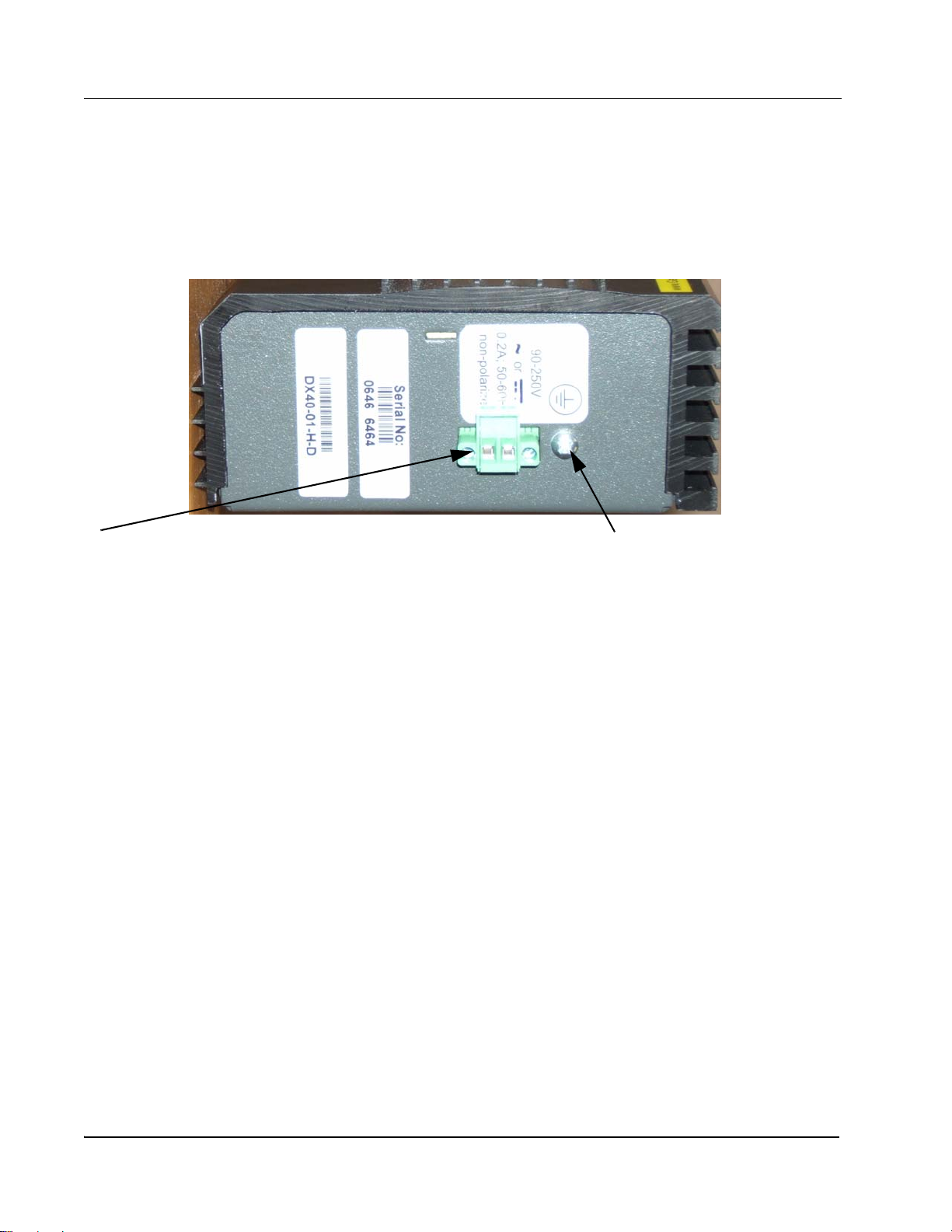
2.3.2.1 Making the Ground and Power Connections
The DX40 provides a hardened DC or AC power supply for industrial applications and/or
hostile environments. The grounding screw and power supply connector are located on
the top of the unit as shown in Figure 2-5.
DX40 Serial Device Router Installation Guide
15
Page 28

CHAPTER 2 - Installation
Installation of the DX40 Unit
Grounding screw
90-250V
~ or
0.2A;50-60Hz
non-polarized
Serial No:
0650 0034
DX40-01-H-D
Non-polarized power input.
Figure 2-5. Ground and Power Connections
ELECTRICAL WARNING: Verify that a proper ground connection is made from the
grounding screw to facility ground prior to connecting power to the DX40. Failure to have
a proper ground path could cause serious injury or death to personnel in cases of power
surges.
Making the Ground Connection
The ground wire should be 14 AWG terminated with a #6 ring lug.
Make the facility ground connection as follows:
1.Loosen the ground screw on the chassis, insert the #6 ring lug, and tighten the
ground screw.
2.Connect the other end of the ground wire to the facility ground.
DX40 Serial Device Router Installation Guide
16
Page 29

CHAPTER 2 - Installation
Installation of the DX40 Unit
#6 terminal lug
ground screw
14 AWG wires
terminal block
Figure 2-6. Power and Ground Properly Connected
Making the Power Connection
The power wires should be 14 AWG. Smaller wires may be used, down to 18 AWG, but
verify that they meet your local electrical requirements.
Connect the power to the unit as follows.
ELECTRICAL WARNING: Ensure that power is disconnected from wiring prior
to handling! Check the voltage rating next to the power connector - verify that
it matches the power source.
1.Remove the plug portion of the power connector by loosening the two captive
mounting screws.
2.Strip back 1/4" off the insulation of the wires that will connect the unit to the
power source.
3.Loosen saddle screw and insert each conductor firmly into a terminal hole of the
plug (note: this connection is not polarity sensitive.)
4.Visually inspect that no strands of wire are straying out of the hole, potentially
shorting to ground or the other conductor. Tighten the saddle screws until the
wires are secure.
5.Re-insert the plug into the power connector and secure the two captive
mounting screws.
DX40 Serial Device Router Installation Guide
17
Page 30

CHAPTER 2 - Installation
Installation of the DX40 Unit
saddle screws
captive mounting screws
2.3.3 Connecting Network Cables
There are three types of connections that can be made to the DX40. They are serial,
Ethernet copper, and Ethernet fiber optic. The following sections describe each type of
connection separately.
2.3.3.1 Connecting Serial Cables
terminal holes
Figure 2-7. Non-Polarized Power Input
This procedure assumes that one end of the Serial device cable is already att ached to the
end unit. Be aware of the serial port numbering scheme when installing the cables (see
Figure 1-1 on page 1). The ports are configured in software later on and if a device is
accidentally connected to the wrong port it will be difficult to detect.
Connect cables to the Serial ports as described below:
1.Align the DB9 connector with appropriate serial port and push gently until the
connector is completely mated to the port.
2.Tighten the two extended capture screws hand tight.
3.Make sure that the connector is not supporting the whole weight of the cable.
Providing strain relief on these cables will ensure a stable connection.
4.Return to step one above and connect the remainder of the serial cables.
2.3.3.2 Connecting Ethernet Copper Cables
If your DX40 is configured with port E2 as a standard RJ45 port, connect a shielded
Ethernet cable to the Ethernet port as follows.(see Figure 1-1 on page 1).
1.Install the RJ45 connector into the port with the clip facing up.
2.Push the RJ45 connector into the slot until you hear a click.
3.Give the cable a gentle tug to ensure that the connector clip is firmly seated.
4.Verify that the connection has been made by checking the LED associated with
this port on the DX40 chassis. It should be illuminated. If the link LED is not
illuminated verify that the equipment on the other end of the cable is powered
up and properly connected.
DX40 Serial Device Router Installation Guide
18
Page 31

CHAPTER 2 - Installation
Maintenance
2.3.3.3 Connecting Fiber Ethernet Cables
Ports E1 (and, optionally, E2) can be configured with SFPs to support fiber optic
connections. These ports accept LC type connectors. The procedure for installing these
connectors is given in Section 2.2.1, “Attaching Optional Ethernet Fiber Optic SFPs”.
Follow the fiber optic safety precautions and steps to install the fiber optic cables to these
ports and refer to Figure 1-1 for Ethernet port locations.
LASER WARNING: DO NOT LOOK INTO A FIBER OPTIC CABLE OR PORT! These can
produce invisible light that may do serious eye damage. Always assume that fiber optic cables or
ports are actively radiating light energy.
Connect cables to the fiber optic ports as described below:
1.Remove the dust cap from the optical port and from the fiber cable end.
2.Inspect the cable end and the port for contamination. If any contamination is
found clean the port or cable according to Section 2.4.2, “Cleaning Fiber Optic
Devices”.
3.Insert the fiber cable connector into the fiber port. Listen for the click that
signifies the connector is properly seated.
4.Give the cable a gentle tug to make sure it is securely installed.
5.Ensure that the cables are properly secured and do not hang freely. Excessive
bending could cause damage to the fiber strand.
6.Return to step one above and connect the remainder of the cables.
2.4 Maintenance
The DX40 is designed to be replaced as a unit. There are no servicing requirements and
there are no user-repairable components in this device. Maintenance is limited to
replacing the unit and cleaning any fiber optic connectors and ports.
The following sections detail disconnecting all connections to the chassis, removing the
chassis, cleaning optical devices and packing the DX40 for return to the manufacturer. If
it is still possible to connect a terminal to the malfunctioning DX40 and retrieve any
configuration data from the device, do so prior to removing power.
2.4.1 Removing the DX40
Removing the DX40 entails disconnecting the network cabling, disconnecting the power
lines and ground lines, and removing the chassis from the rack or other installation
location. The unit can then be packed for shipment to the manufacturer.
DX40 Serial Device Router Installation Guide
19
Page 32

CHAPTER 2 - Installation
Maintenance
2.4.1.1 Disconnecting Network Cables
The sequence for removal of the serial and Ethernet cables is not important, but it is
important to note that there are active devices connected to each end of the cable.
1.Remove all of the Async DB9 connectors from the serial ports by unscrewing
the two captive screws on each cable and pulling the connector off the port.
(Label the connector with the port number if the cable is to be reconnected at
some later time.)
2.Remove the Ethernet RJ45 connectors from the Ethernet ports by pressing on
the clip on the underside of the modular connector and pulling the connector
straight out. (Label the connector with the port number if the cable is to be
reconnected at some later time.)
LASER WARNING: DO NOT LOOK INTO A FIBER OPTIC CABLE OR PORT! These can
produce invisible light that may do serious eye damage. Always assume that fiber optic cables or
ports are actively radiating light energy.
3.Following the safe handling procedures for fiber optic cables and connectors,
remove any fiber optic cable connected to the Ethernet fiber ports. Immediately
install dust caps on the cable end and the fiber port. (Label the connector with
the port number if the cable is to be reconnected at some later time.)
2.4.1.2 Disconnecting Power and Ground Lines
ELECTRICAL WARNING: Before disconnecting either AC or DC power connections at the
DX40 ensure that the facility power has first been turned off. Failure to shut power off prior
to removing the power connections could expose you to dangerous voltages causing
injury or death.
Follow the procedure below to disconnect the power and ground lines.
1.Verify that power to the DX40 is turned off.
2.Use a screw driver to loosen the two screws that tighten the wire clamps in the
non-polarized power connector. Remove the wires from the connector.
ELECTRICAL WARNING: If the wires are not to be used immediately properly
insulate them to ensure that an accidental turning on of the power will not
cause a short or electrical hazard.
3.Remove the ground wire from the chassis by loosening the grounding screw.
2.4.1.3 Packing the DX40 for Shipment
If you have saved the shipping box that your DX40 was received in then add the end
styrofoam pieces around the chassis and place the unit in the box. Please contact
customer support to receive a valid RMA number so that this item is either repaired and
returned or credited to your account. Products without a proper RMA number will not be
accepted for repair by GarrettCom Utility Networks.
20
DX40 Serial Device Router Installation Guide
Page 33

CHAPTER 2 - Installation
Maintenance
If you have not saved the original shipping container then place the unit in a box so that
normal shipping activities will not cause any damage to the unit. GarrettCom Utility
Networks has no responsibility for the product during return shipping. For more warranty
information, see “Warranty” on page ii, and for details for the requirements for returning
equipment, see “Return Of Equipment” on page iii.
2.4.2 Cleaning Fiber Optic Devices
This section covers the cleaning requirements and procedures for the fiber optic cable
connectors and the optical ports on the DX40. Clean the connectors after each use and
the optical ports when contamination is suspected or there is a performance degradation
which may be attributable to contamination. All fiber optic connectors and optical ports
should be capped with dust caps when not in use.
The cleaning materials used should be rated for fiber optic devices. Specifically cloth,
wipes and swabs should be lint-free, non-abrasive and free of additives. Cleaning fluids
should be restricted to optical-grade isopropyl alcohol. Canned (compressed) air should
be used to blow out dust and particulate matter and to dry residual isopropyl alcohol after
cleaning.
2.4.2.1 Cleaning Connectors
These instructions are recommended each time a fiber optic connector is use d. Clean the
fiber optic connectors as follows:
1.Blow out any dust or particulate matter from the connector end, using canned
air.
2.Wipe out the connector end surfaces with a cloth or pad saturated in isopropyl
alcohol.
3.Blow dry the connector surfaces, using canned air, by directing the air flow
across the tip but not directly down onto the tip.
4.Using care not to touch the fiber tip, install a dust cap or connect to an optical
port.
2.4.2.2 Cleaning Optical Ports
These instructions are recommended only when there is evidence of contamination or
when reduced performance has been detected. Clean the optical ports as follows:
1.If required, remove the fiber optic connector from the optical port and clean the
connector as described in “Cleaning Connectors,” above.
2.Insert the extension tube, supplied with the canned air, into the canned air
nozzle and blow out the optical port. Use care not to touch the bottom of the
optical port.
3.Reconnect the fiber optic connector removed in step 1.
DX40 Serial Device Router Installation Guide
21
Page 34

CHAPTER 2 - Installation
Maintenance
If degraded performance persists, perform the following additional steps:
4.Remove the fiber optic connector and place a dust cap on the end.
5.Using a small-head, lint-free swab gently wipe out the optical port. Repeat steps
2 and 3.
22
DX40 Serial Device Router Installation Guide
 Loading...