

Page 1
Owner’s
Manual
&
Reference
GPS3 8
Personal
Navigator
®
Page 2

Software Version 3.0 or above
© 1997 GARMINCorporation
1200 E. 151st Street, Olathe, KS USA 66062
Tel: 913-397-8200 or 800-800-1020
Fax: 913-397-8282
Web Site Address: www.garmin.com
GARMIN (Europe) Ltd.
Unit 5, The Quadrangle, Abbey Park, Romsey, U.K. SO51 9AQ
Tel: 011-44-1794-519944
Fax: 011-44-1794-519222
All rights reserved. No part of this manual may be reproduced or transmitted in any
form or by any means, electronic or manual, including photocopying and recording, for
any purpose without the express written permission of GARMIN.
Information in this document is subject to change without notice. GARMIN reserves
the right to change or improve their products and to make changes in the content without obligation to notify any person or organization of such changes or improvements.
GARMIN, GPS 38, Personal Navigator, AutoLocate and MultiTrac8 are all trademarks of GARMIN Corporation, and may not be used without the expressed permission
of GARMIN.
June 1997 Part #190-00112-00 Rev. B Printed in Taiwan.
Page 3

I N T R O D U C T I O N
GPS 38
Personal Navigator
TM
Preface
OWNER’S MANUAL
Welcome to the smallest, easiest-to-use GPS navigator for recreational use!
The GPS 38 represents GARMIN’s continuing commitment to provide outdoors sports enthusiasts with quality navigation information in a versatile,
accurate and user-friendly design you’ll enjoy for years to come. To get the
most of your new GPS unit, it is important that you take the time to read
through this owner’s manual to understand the operating features of the GPS
38. The manual is organized into three sections for your convenience:
Section One takes provides step by step instructions to initialize the
receiver for first time use.
Section Two introduces you to the basic features of the unit and provides
a quick-start orientation to the GPS 38. It has been designed to acquaint you
with the unit and provide a basic working knowledge necessary to use the
unit in typical conditions.
Section Three provides a detailed reference to the advanced features and
operations of the GPS 38 in a topical format. This allows you to concentrate
on a specific topic quickly, without reading through entire sections of text that
you may not need.
Packing List
Before getting started with your GPS, check to see that your GARMIN
GPS 38 package includes the following items. If you are missing any parts,
please contact your dealer immediately.
Standard Package:
• GPS 38 Receiver • Wrist Strap
• GPS 38 Owner’s Manual • Quick Reference Card
Thanks for choosing the GARMIN GPS 38. We hope it will help you get
the most out of your outdoor recreation adventures.
i
Page 4

I N T R O D U C T I O N
Caution
The GPS system is operated by the government of the United States,
which is solely responsible for its accuracy and maintenance. The system is
subject to changes which could affect the accuracy and performance of all
GPS equipment. Although the GPS 38 is a precision electronic NAVigation
AID (NAVAID), any NAVAID can be misused or misinterpreted, and therefore
become unsafe.
Use the GPS 38 at your own risk. To reduce the risk of unsafe operation, carefully review and understand all aspects of this Owner’s Manual and
thoroughly practice operation using the simulator mode prior to actual use.
When in actual use, carefully compare indications from the GPS 38 to all
available navigation sources including the information from other NAVAIDs,
visual sightings, charts, etc. For safety, always resolve any discrepancies before
continuing navigation.
NOTE: This device complies with Part 15 of the FCC limits for Class B
digital devices for home or office use. This equipment generates, uses, and
can radiate radio frequency energy, and if not installed and used in accordance with the instructions, may cause harmful interference to radio communications. However, there is no guarantee that interference will not occur in a
particular installation. If this equipment does cause harmful interference to
other equipment, which can be determined by turning the equipment off and
on, the user is encouraged to try and correct the interference by relocating the
equipment or connecting the equipment to a different circuit than the affected
equipment. Consult an authorized dealer or other qualified service technician
for additional help if these remedies do not correct the problem. Operation is
subject to the following conditions: (1) This device may not cause harmful
interference, and (2) this device must accept any interference received,
including interference that may cause undesired operation. The GPS 38 does
not contain any user-serviceable parts. Repairs should only be made by an
authorized GARMIN service center. Unauthorized repairs or modifications
could void your warranty and your authority to operate this device under Part
15 regulations.
CAUTION
ii
Page 5

I N T R O D U C T I O N
Table of
Contents
SECTION ONE Introduction
GPS Overview/Navigation Basics . . . . . . . . . . . . . . . . . . . . . . . . . . . .2-3
Battery Installation . . . . . . . . . . . . . . . . . . . . . . . . . . . . . . . . . . . . . . .4
Initializing the Receiver . . . . . . . . . . . . . . . . . . . . . . . . . . . . . . . . . .5-8
SECTION TWO Getting Started
Power On/Satellite Page . . . . . . . . . . . . . . . . . . . . . . . . . . . . . . . . . . . .9
Sky View/Position Page . . . . . . . . . . . . . . . . . . . . . . . . . . . . . . . . . . .10
Marking a Position . . . . . . . . . . . . . . . . . . . . . . . . . . . . . . . . . . . . . .11
Position and Map Basics . . . . . . . . . . . . . . . . . . . . . . . . . . . . . . . . . .12
GOTO and Steering Guidance . . . . . . . . . . . . . . . . . . . . . . . . . . .13-14
Page Sequence and Menu Page . . . . . . . . . . . . . . . . . . . . . . . . . . . . . .15
Clearing the Track Log/Power Off . . . . . . . . . . . . . . . . . . . . . . . . . . . .16
SECTION THREE Reference
Satellite Page . . . . . . . . . . . . . . . . . . . . . . . . . . . . . . . . . . . . . . . .15-19
Position Page . . . . . . . . . . . . . . . . . . . . . . . . . . . . . . . . . . . . . . . . . . .20
Creating and Using Waypoints . . . . . . . . . . . . . . . . . . . . . . . . . . .21-27
GOTO and MOB Mode . . . . . . . . . . . . . . . . . . . . . . . . . . . . . . . . . . .28
TracBack Navigation . . . . . . . . . . . . . . . . . . . . . . . . . . . . . . . . . . .29-30
Creating and Using Routes . . . . . . . . . . . . . . . . . . . . . . . . . . . . . .31-36
Compass and Highway Page Steering Guidance . . . . . . . . . . . . . . .37-39
Map Plotting . . . . . . . . . . . . . . . . . . . . . . . . . . . . . . . . . . . . . . . .40-43
Menu Page and Auxiliary Functions . . . . . . . . . . . . . . . . . . . . . . .44-52
Simulator Mode . . . . . . . . . . . . . . . . . . . . . . . . . . . . . . . . . . . . . . . .53
Appendix A—Messages/Time Offsets . . . . . . . . . . . . . . . . . . . . . . .54-55
Appendix B—Map Datums . . . . . . . . . . . . . . . . . . . . . . . . . . . . . .56-57
Appendix C—Specifications and Wiring . . . . . . . . . . . . . . . . . . . .58-59
Appendix D—Accessories . . . . . . . . . . . . . . . . . . . . . . . . . . . . . . . . .60
Appendix E—Index . . . . . . . . . . . . . . . . . . . . . . . . . . . . . . . . . . .61-62
1
Page 6

I N T R O D U C T I O N
Glossary
Almanac Data—Satellite constellation information (including location and health of
satellites) that is transmitted to your receiver from every GPS satellite. Almanac data
must be acquired before GPSnavigation can begin.
Bearing—The compass direction from your position to a destination.
Course Made Good (CMG)—The bearing from the “active from” position (your start-
ing point) to your present position.
Crosstrack Error (XTE)—The distance you are off a desired course in either direction.
Desired Track (DTK)—The compass course between the “from” and “to” waypoints.
Differential GPS (DGPS)—An extension of the GPSsystem that uses land-based radio
beacons to transmit position corrections to GPS receivers.
Estimated Time of Arrival (ETA)—The time of day of your arrival at a destination.
Estimated Time Enroute (ETE)—The time left to your destination at your present
speed.
Grid—A coordinate system that projects the earth on a flat surface, using square zones
for position measurements. UTM/UPS and Maidenhead formats are grid systems.
Ground Speed—The velocity you are traveling relative to a ground position.
Latitude—A north/south measurement of position perpendicular to the earth’s polar
axis.
Longitude—An east/west measurement of position in relation to the Prime Meridian, an
imaginary circle that passes through the north and south poles.
Navigation—the process of traveling from one place to another and knowing where
you are in relation to your desired course..
Position—An exact, unique location based on a geographic coordinate system.
Track (TRK)—The direction of movement relative to a ground position.
Universal Transverse Mercator (UTM)— A grid coordinate system that projects
global sections onto a flat surface to measure position in specific zones.
Velocity Made Good (VMG)—The speed you are traveling in the direction of the
destination.
Waypoint—A specific location saved in the receiver’s memory.
The GPS 38 is a powerful navigation tool that can guide
you anywhere in the world. To better understand its operation and capabilities, it may be helpful to review the basic
terms and concepts briefly explained below.
Other navigation and GPS definitions used in the manual are defined in the appropriate sections of the reference
section of the manual.
2
Page 7
B
P
M
G
E
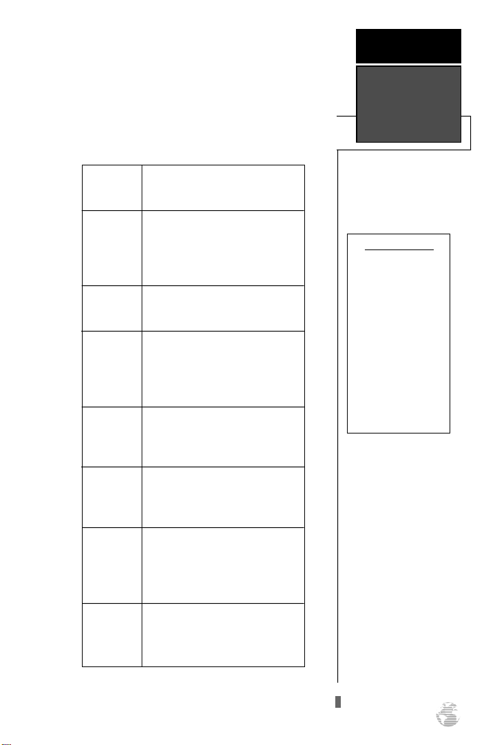
Turns the unit on and off and
activates screen backlighting.
Scrolls through the main data
pages in sequence and returns
display from a submenu page
to a primary page.
Captures a position and displays the mark position page.
Displays GOTO page with
the waypoint highlighted for
GOTO operation. Pressing
GOTO twice activates MOB.
Confirms data entry and
activates highlighted fields
to allow data entry.
I N T R O D U C T I O N
Keypad Usage &
Data Entry
DATA ENTRY
The arrow keypad is
used for all data entry.
Use the U and D
keys to select letters,
numbers, and menu
options; use the L and
R keys to move the cur-
sor forw a rd or backw a rd along the line.
Press E to confirm
your entry.
Q
UD
L R
Returns display to a previous
page, or restores a data field’s
previous value.
Selects alphanumerical
characters and menu choices
and moves the field highlight
from field to field.
Moves the selected character
field and moves the field
highlight from field to field.
3
Page 8
G E T T I N G
S TA R T E D
Battery
Installation
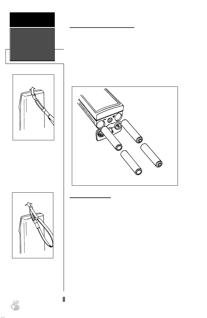
Wrist Strap Attachment
To attach the GPS 38’s wrist
strap, slide the small loop
end of the strap through the
slot at the top of the GPS.
Getting Started with your GPS
Welcome to the exciting world of GARMINGPS! The
GPS 38 represents GARMIN’s continuing commitment to
provide outdoor enthusiasts with quality navigation information in a versatile, user-friendly design you’ll enjoy for
years to come. To get the most out of your GPS, be sure to
read through the initialization and getting started sections
of this manual and refer to the reference section for complete details on the GPS 38’s advanced features.
T h read the strap thro u g h
the small loop eye and draw
the strap tight.
4
Battery Installation
The GPS 38 uses 4 AA batteries to provide up to 12
hours of operation in normal mode and up to 20 hours of
operation in battery saver mode using alkaline batteries.
Rechargeable Ni-Cad or lithium batteries may also be used.
Note that the battery level indicator is calibrated for alkaline batteries, and Ni-Cad or lithium batteries will only
show battery life at partial scale.
To install batteries:
1. Remove the battery cover by turning the thumb loop at the
bottom of the unit 1/4 turn counter-clockwise.
2. Insert batteries into position. The battery pole you can still
see should match the symbol marked on the case.
3. Replace and secure the battery cover by turning the thumb
loop 1/4 turn clockwise.
Page 9
Initializing Your GPS for First Time Use
The GPS 38 calculates your position and movement by
tracking signals sent from GPS satellites. Each of the 24
GPS satellites circle the earth twice a day in a very precise
orbit, and transmit information back to earth. In order to
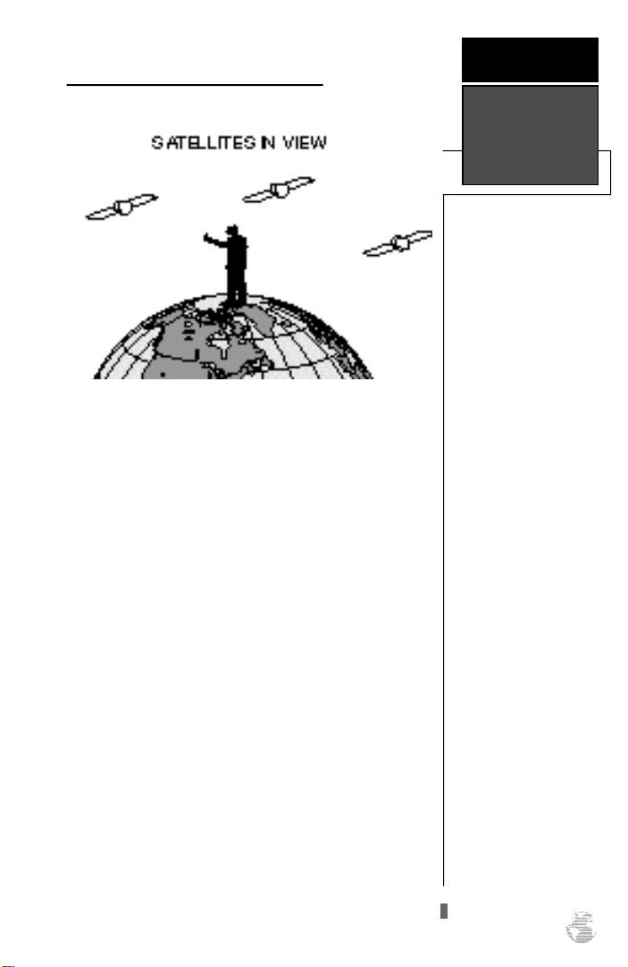
determine a position fix, your GPS receiver needs to continuously “see” at least three satellites.
Because a GPS receiver can only see satellites above the
horizon, it needs to know what satellites to look for at any
given time. By using an almanac (a timetable of satellite
numbers and their orbits) stored in the receiver’s memory,
the GPS 38 can determine the distance and position of any
GPS satellite.
To use this almanac data, your GPS needs to know
where you are, or be given the opportunity to “find itself”.
Once you initialize the unit to this position, the GPS 38
will usually compute a fix within a few minutes.
Remember, this process is only necessary under the
following conditions:
• First time use from the factory.
• The receiver has been moved over 500 miles from
the last calculated position with power off.
• The receiver’s memory has been cleared and all
stored data has been lost.
G E T T I N G
S TA R T E D
Initialization
5
Page 10
G E T T I N G
S TA R T E D
Acquiring
Satellites
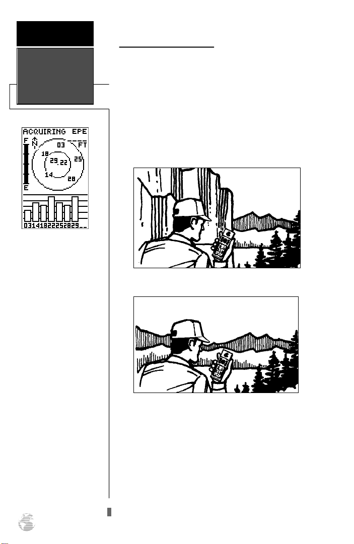
The GPS 38’s Satellite Page
will help you determ i n e
what satellites are in view,
and whether or not any
satellites are being “shaded”, or blocked from the
receiver’s antenna.
By monitoring the signal
strength bars at the bottom
of the page and the north up
sky view, you’ll be able to
see how moving to another
area with a clearer view of
the sky will improve satellite
reception and speed up sig-
nal acquisition.
Acquiring Satellite Signals
Because the GPS 38 relies on satellite signals to provide
you with navigation guidance, the receiver needs to have an
unobstructed, clear view of the sky for best performance.
What exactly does this mean? In a nutshell, the GPS receiver’s view of the sky will generally determine how fast you
get a position fix, or if you get a fix at all. GPSsignals are
relatively weak, and do not travel through rocks, buildings,
people, mountains and other significant structures, so you
need to make sure that you’re not standing next to a tall
building or a wall of cliffs when acquiring satellites.
Obstructed View of the Sky
Clear View of the Sky
Once the GPS has calculated a position fix, you’ll usually have anywhere from four to eight satellites in view. The
GPS 38 will now continuously select the best satellites in
view to update your position. If some of the satellites in
view get blocked or “shaded”, the receiver can simply use
an alternate satellite to maintain the position fix. Although
a GPS receiver needs four satellites to provide a 3D fix, the
GPS 38 can maintain a 2D fix with only three satellites.
6
Page 11
Before You Initialize
Take the GPS 38 outside and find a large, open area (try
a nearby park) that has a clear view of the sky from horizon
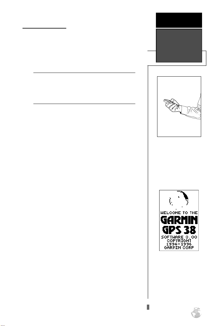
to horizon. Hold the receiver at a comfortable height, at
arm’s length from your body with the built-in antenna (the
top part above the display) parallel to the ground.
Do your best to stay away from buildings or other
!
structures that could block the path of signals to the
#
receiver. GPS signals do not travel through rocks,
mountains, buildings, metal surfaces or other significant structures.
To turn the GPS 38 on:
1. Hold the unit so the built-in antenna (the flat area above
the display) is parallel to the ground.
2. Press and hold Buntil the receiver turns on.
The welcome page will be displayed while the unit conducts a self test. Once testing is complete, the welcome
page will be replaced by the Satellite Page, with the EZinit
prompt ready for you to select one of two initialization
methods:
• Select Country— allows you to initialize the receiver
by selecting your present position from a list of coun-
tries in the GPS 38’s internal database. Usually provides a position fix in a few minutes.
• AutoLocateTM— allows the GPS 38 to initialize itself
and calculate a position fix without knowing your
present position. Usually provides a position fix in
7.5-15 minutes.
If the EZinit prompt has not automatically appeared
on the Satellite Page:
1. Press the Ekey.
If you’ve already initialized the GPS 38 and the EZinit
prompt appears, highlight the ‘NO RE-INIT’ selection with
the arrow keypad and press E. The EZinit prompt may
appear if you’ve had the unit on in normal mode while
indoors, or if the antenna is shaded while acquiring satellites in normal or battery saver mode.
G E T T I N G
S TA R T E D
Powering Up
Hold the receiver so the
built-in antenna is parallel
to the ground.
Welcome Page
7
Page 12
G E T T I N G
S TA R T E D
EZinit
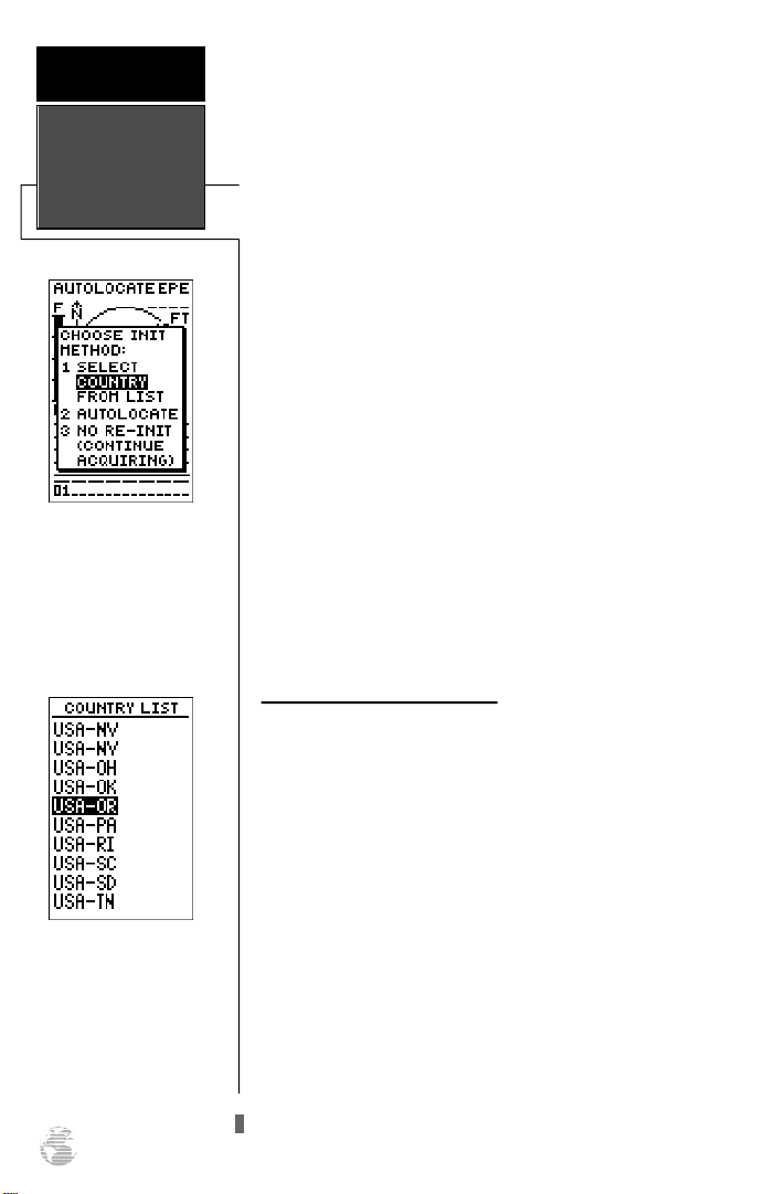
The EZinit prompt will
automatically appear if the
receiver needs to be initialized. The prompt may also
appear during normal use if
the antenna is shaded or the
unit is indoors.
Use the arrow keypad to
highlight the country and
region or state (if necessary)
of your present position
f rom the list and pre s s
ENTER. If the country is
not listed, select the closest
country instead.
8
To initialize the receiver:
1. If the ‘country’ option is not highlighted, press theDkey
repeatedly to move the field highlight to the ‘country’
option.
2. Press the Ekey.
3. Use theDkey to scroll through the list pages until the
country of your present position appears.
4. Use theU key to highlight the country/state/region
you’re in. If the country you’re in is not listed, select another country within 500 miles of your present position.
5. Press Eto finish.
The GPS 38 will now begin searching for the appropriate satellites for your position and should acquire a fix
within a few minutes. You can verify that you have acquired
a fix by watching the Satellite Page transition to the Position
Page (provided you haven’t pressed any other buttons) or
looking for a 2D or 3D NAV status at the top left corner of
the Satellite Page. To prevent accidental battery power loss,
the GPS 38 will automatically shut off 10 minutes after the
last keystroke if the unit is not tracking at least one satellite
and has never acquired a position fix.
Initialization Troubleshooting
If you have trouble initializing the receiver or getting a
position fix, check the following:
• Does the receiver have a clear view of the sky?
If there are large buildings, rocks, mountains, or heavy
tree cover, the receiver may not be receiving enough
satellite signals to calculate a fix.
• Have you selected the right country/state from the
EZinit list?
Check for the correct approximate lat/lon on the
Position Page or reselect the appropriate country from
the list to restart the initialization.
• Have you moved more than 500 miles from the last
calculated position with the receiver off?
Reinitialize the receiver, selecting the country/state of
your new location from the EZinit list.
Page 13
Getting Started Tour
Now that your GPS has been initialized, it’s time to take
a tour through the GPS 38’s basic features and functions.
The tour assumes that you have initialized the receiver and
have not changed any of the factory settings (units of measure, selectable fields, etc). If you have changed any of the
default settings, the pictures and descriptions may not
match your unit’s configuration.
Powering Up and Taking a Fix
Take the GPS 38 outside and find an open area where
the receiver will have a clear view of the sky. Hold the
receiver at a comfortable height, at arm’s length from your
body, with the internal antenna parallel to the ground.
To turn the unit on:
1. Press and hold Buntil the receiver turns on.
A welcome page will be displayed while the unit conducts a self test. Once testing is complete, the welcome
page will be replaced by the Satellite Page and the GPS 38
will begin acquiring satellites.
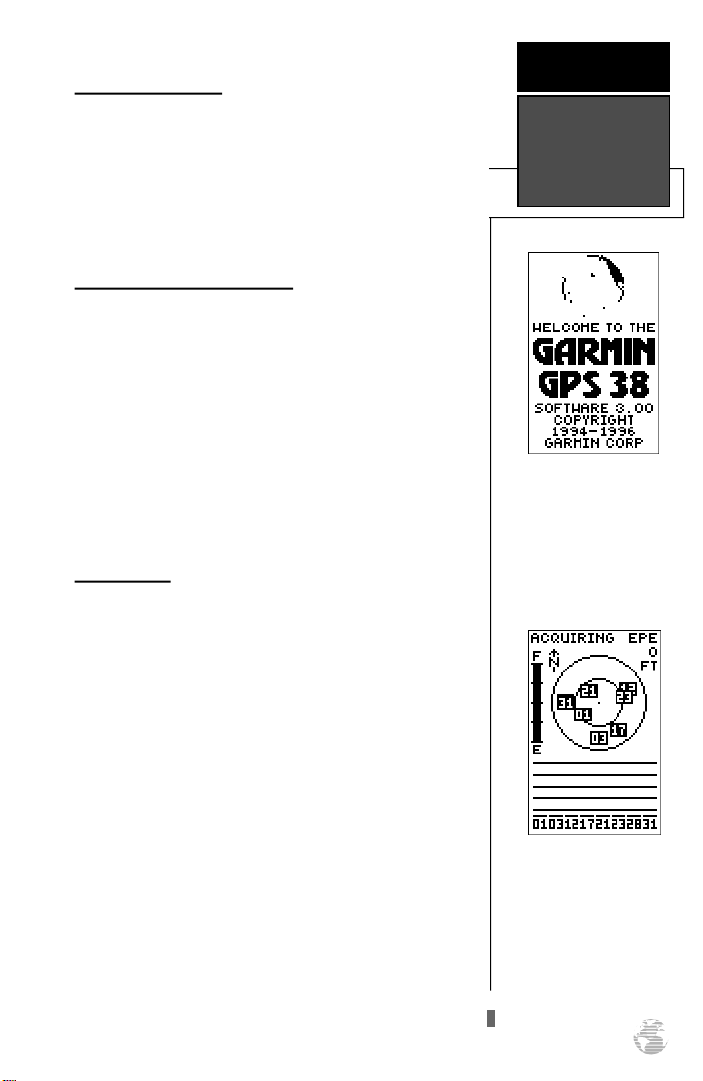
Satellite Page
The GPS 38’s Satellite Page provides a visual reference
of satellite acquisition and position. As the receiver locks
onto satellites, a signal strength bar will appear for each
satellite in view, with the appropriate satellite number (1-
32) underneath each bar. The progress of satellite acquisition is shown in three stages:
• No signal strength bars— the GPS 38 is looking
for the satellites indicated.
• Hollow signal strength bars— the GPS 38 has
found the satellite(s) and is collecting data.
• Solid signal strength bars— the GPS 38 has collected the necessary data and the satellite(s) is
ready for use.
Note that each satellite has a 30 second data transmission that must be collected (hollow bar status) before the
satellite may be used for navigation (solid bar status). Once
a fix has been calculated, the GPS can take on the easier
task of updating your position, track and speed by selecting
and using the best satellites in view.
G E T T I N G
S TA R T E D
Power On/
Satellite Status
Welcome Page
Satellite Page
The signal strength bars at
the bottom of the page will
not appear until the GPS 38
has found the sate llites
indicated at the bottom of
the screen.
9
Page 14
G E T T I N G
S TA R T E D
Status
Horizontal
Accuracy
Sky View &
Position Page
Once satellites have been
found, hollow signal strength
bars will be displayed while
data is being collected. The
hollow bars can be used to
help determine if satellites
are being shaded.
Battery
Indicator
Satellite
Number
Satellite
Sky View
Signal Strength
Indicators
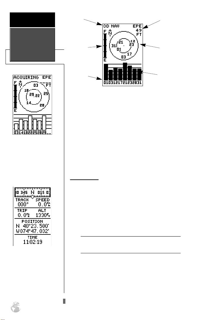
The Satellite Page shows a bird’s eye view of the position of each satellite relative to the unit’s last known position. The outer circle represents the horizon (north up); the
inner circle is 45º above the horizon; and the center point
is directly overhead. You can use the sky view to help
determine if any satellites are being blocked, and whether
you have a current position fix (indicated by a ‘2D NAV’ or
‘3D NAV’ in the status field.
Once sufficient signals have been acquired, the Satellite
Page will be replaced with the Position Page, provided you
have not pressed any other buttons.
Position Page
The second page in the GPS 38’s primary page sequence
is the Position Page. The Position Page shows you where
you are, what direction you’re heading and how fast you
are going, and is particularly helpful when you do not have
an active destination selected. The graphic display at the
top of the page indicates your heading (only while you’re
moving) with the track and speed indicated below.
Position Page
In addition to disp laying
your position coord i n a t e s ,
the Position Page shows
your track and speed over
the ground. Speed and altitude data may fluctuate due
to Selective Availability.
10
The graphic compass tape reflects your heading
!
#
only while you are moving.
The rest of the page shows your current position in
three dimensions: latitude, longitude and altitude. The
GPS 38 uses this basic information to mark exact positions
as waypoints, which help guide you from one place to
another. A trip odometer and 12/24 hour clock are also
provided.
Page 15
Marking a Position
G E T T I N G
S TA R T E D
Now that you’ve acquired a position, let’s mark it as a
waypoint for future reference.
1. Press the Mkey to capture and hold your position.
To mark a position, you must have obtained a 2D or
!
#
3D fix, or have the receiver in simulator mode. If
you try to mark a position without a position fix, you
will be alerted with a ‘No GPS Position’ message.
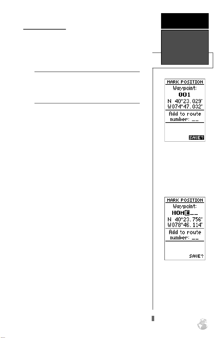
The mark position page will appear, showing the captured position and a default 3-digit waypoint name. Let’s
change the default name to something that’s a little more
meaningful, like ‘HOME’.
1. Press theUkey twice to move the field highlight from
the ‘SAVE?’ field to the name field.
2. Press Eand Lto clear the default waypoint name.
3. Press and hold theUkey to scroll through the alphabet
until the letter ‘H’ appears.
4. Press the Rkey once to move the character highlight to
the next character space.
5. Repeat steps 3 and 4 until the word ‘HOME’ is displayed.
Marking a
Position
To save a waypoint with the
default three digit n ame,
simply press the ENTER
key. The GPS 38 will return
to the page previously
displayed.
6. Press Eto complete entry of the name.
7. Press the Dkey once to return the field highlight to the
‘SAVE?’ field.
8. Press the Ekey to confirm that you want to save the
position as a waypoint named ‘HOME’.
The mark position page will now be replaced by the
Position Page (or the page displayed prior to pressing the
key). The ‘HOME’ waypoint is now stored in the GPS
M
38’s memory, and will remain there until you manually
remove it or clear the receiver’s memory. For more on way point management, see pages 21-27.
The arrow keypad is used
for all data entry. Use the
UP and DOWN k eys to
select letters, numbers or
menu options; use the LEFT
and RIGHT keys to move
the cursor forward or backward along the line.
11
Page 16
G E T T I N G
S TA R T E D
Using the Position and Map Pages
Position Page &
Map Page
Map Page
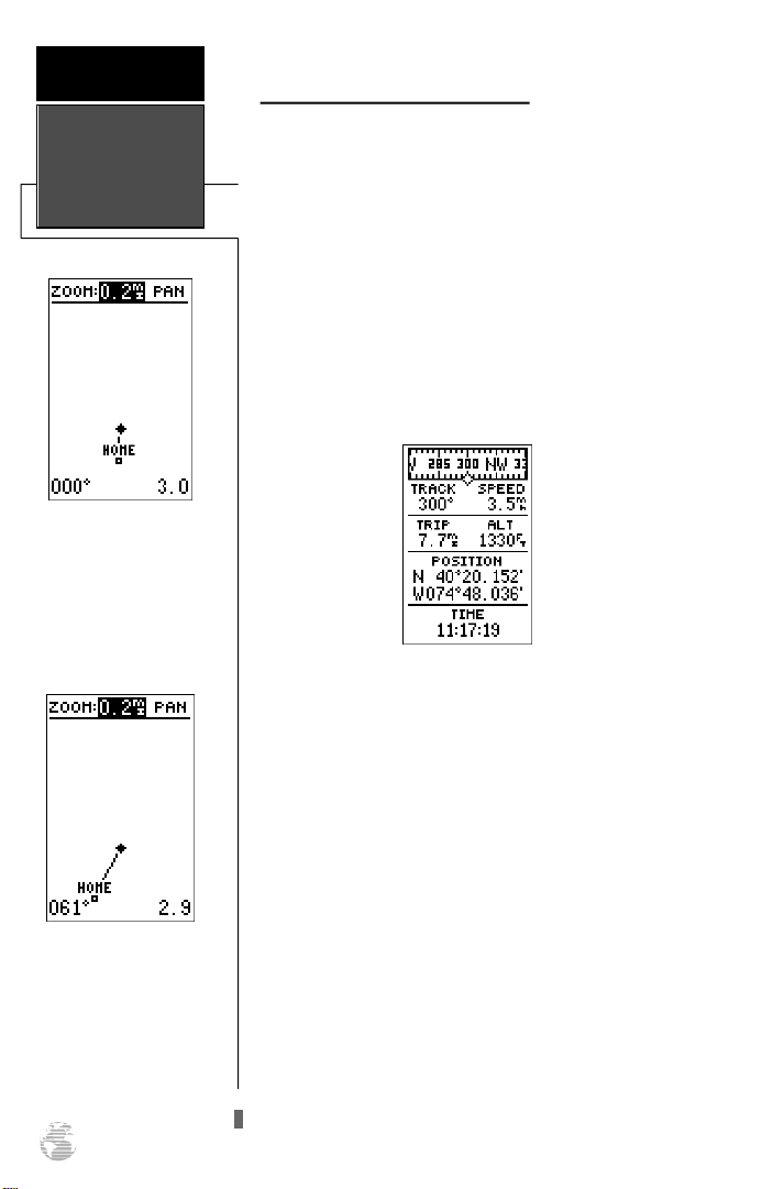
The Map Page displays
your present position as a
diamond icon and provides
a real time graphic “breadc rumb” display of your
track right on screen.
Now that you’ve marked a position, it’s time to take off
on a brisk walk, using the position and Map Pages to watch
your every move. To get the most out of this tutorial, be
sure to walk for at least the time noted for each step. This
way, you’ll reduce the chances of staying within the margin
of error of the GPS system (usually around 15 meters).
You’ll also get a much better indication of how the GPS38’s
steering guidance and mapping features work to guide you
wherever you go.
1. Walk in a straight line for 3-4 minutes at a fast pace and
watch the Position Page. You can time your distance with
the on-screen clock.
The direction you are moving (your track) and your
speed are displayed on the upper part of the screen, just
below the graphic compass tape. The latitude, longitude
and approximate altitude of your position; along with a
resettable trip odometer, are continuously displayed in the
middle of the page, with the time of day displayed below.
Now let’s change the display to the Map Page and watch
the track log of our walk:
The moving map’s default
setting is track up orienta-
tion. It can also be set for
north up, or desired track
up orientation through the
map setup page.
12
1. Press the Pkey to change from the Position Page to
the Map Page.
Your current position is shown as the diamond in the
middle of the screen. The dark circle below the diamond
represents the position you created, with the line between
the two showing your track.
1. Now turn 90º to your right and continue walking at a fast
pace for another 2-3 minutes. Notice how the display
changes, always keeping the direction you are moving at
the top of the map.
Page 17

Going To a Waypoint
G E T T I N G
S TA R T E D
Once you’ve stored a waypoint in memory, you can use
the GPS 38 to guide you to it by performing a simple
GOTO. A GOTO is really nothing more than the receiver
drawing a straight line course from your present position to
the destination you’ve selected. To see how it works, let’s
try navigating back to our starting position, the HOME
waypoint.
To select a GOTO destination:
1. Press the Gkey.
2. The go to waypoint page will appear, displaying all the
waypoints in memory in alphabetical order.
3. Use Uor Dto highlight the ‘HOME’ waypoint.
4. Press the Ekey to confirm that you want to navigate
to the displayed waypoint.
Destination
Waypoint
Graphic
Compass Ring
Speed Over
Ground
Going To A
Waypoint
The GOTOwaypoint page
allows you to select your
destination from a list of all
available waypoints in the
GPS 38’s memory.
Track Over
Ground
Compass Page
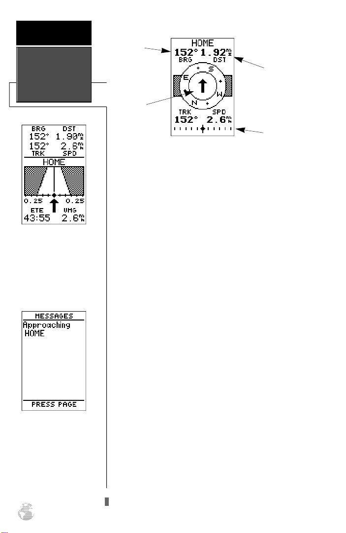
Whenever you select a destination waypoint, the GPS
38 will provide graphic steering guidance with the
Compass Page. As you begin walking again, the Compass
Page will display nav data and graphic steering guidance to
the destination. The bearing (BRG) and distance (DST) to
the waypoint are displayed at the top of the page, right
below the destination waypoint field. The distance displayed is always the straight line distance from your present
position to the destination waypoint. The bearing indicates
the exact compass heading from you to the destination.
Once a GOTO is activated,
the GPS 38 will pro v i d e
steering guidance to the destination until the GOTO is
cancelled. To cancel a
GOTO, highlight the cancel
prompt at the bottom of the
page and press ENTER.
13
Page 18
G E T T I N G
S TA R T E D
Using the
Compass Page
Highway Page
The GPS 38 will also provide steering guidance with
a graphic Highway Page. To
change the display from the
compass to the Highway
Page, press ENTER twice.
Message Page
Once you are one minute
from the destination (based
on your present speed and
course), an arrival message
will be appear on the mes-
sage page.
Bearing to
Waypoint
Distance to
Waypoint
Pointer to
Waypoint
CDIScale
The middle of the Compass Page features a rotating “compass” that shows your current heading while you’re moving ,
with a pointer arrow to the destination displayed in the center.
The arrow shows the direction of your destination from the
d i rection you are moving. If the arrow points up, you are
going directly to the waypoint. If the arrow points any other
d i rection than up (left, right, down, etc.), turn toward the
a rrow until it points up and then continue in that dire c t i o n .
The bottom of the Compass Page displays your curre n t
track (TRK) and speed (SPD) over the ground, while the CDI
(course deviation indicator) scale shows how far you are off
course. The diamond in the center of the CDI scale re p re s e n t s
your present position, while the d-bar (the moving vert i c a l
line on the scale) indicates the direction and distance you are
o ff the desired straight line course.
The default setting of the CDI scale is +/- 0.25 miles, with
each mark re p resenting 0.05 miles of course deviation. If you
do get off course by more than the selected scale, an arro w
p rompt will appear at the end of the scale to indicate the
d i rection you are off course. For more information on setting
the CDI scale, see page 47.
When you are one minute away from the destination
(based on your current speed and track over the ground), the
GPS 38 will alert you with a flashing on-screen message box.
To view a message:
1. Press the Pkey when the message box appears.
2. Press Pagain to return to the previous page.
When the DST field displays a distance of 0.00 miles,
you’ve reached your destination!
14
Page 19
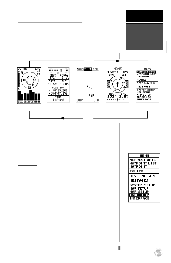
Scrolling Through the Primary Pages
Now that you’ve arrived ‘HOME’, let’s take a minute to
see how the GPS 38’s primary pages work together. T h e
GPS 38 features five primary pages, which are linked together
in a chain. You can quickly scroll through the pages in either
d i rection using the Pand Qkeys.
J
Q
1. Press the Pkey to scroll through the five primary
pages in sequence.
2. Press the Qkey to scroll through pages in the opposite direction.
G E T T I N G
S TA R T E D
Primary Pages
Menu PageCompass PageMap PagePosition PageSatellite Page
Menu Page
You’ve already seen the first four pages in action by
acquiring satellites, marking a position and navigating to a
destination. The last page available from the primary page
sequence is the Menu Page, which provides access to the
GPS 38’s waypoint management, route, track log and setup
features. The 11 submenus are divided into categories by
function.
To select a submenu from the Menu Page:
1. Press Por Quntil the Menu Page appears.
2. Use the Uor Dkeys to highlight the submenu you
want to view.
3. Press Eto access the submenu.
Menu Page
Use the UP and DOWN
keys to select a submenu
from the Menu Page. Press
ENTER to access the selected submenu.
15
Page 20
G E T T I N G
S TA R T E D
Clearing A Cluttered Map
Clearing The
Map & Power
Off
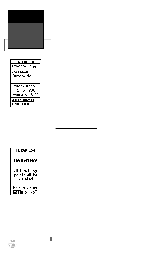
Highlight the CLEARLOG?
prompt and press ENTERto
clear the track log. Once all
768 points are used, the oldest point will be continuously deleted to make room for
the latest track log point.
After you’ve used the GPS38 for a few trips, you may
find that your map display has become a bit messy from
keeping track of your every move. To get a feel for how the
Menu Page works, let’s clear the track log (the plot points
left on the Map Page) we’ve just created during the Getting
Started Tour.
1. Press Por Quntil the Menu Page appears.
2. Use theDkey to move the field highlight to the
‘TRACKLOG’ option.
3. Press Eto access the track log page.
4. Press theUkey twice to highlight the ‘CLEARLOG?’
option. The clear log confirmation page will appear.
5. Use the Lkey to highlight the ‘Yes?’ prompt.
6. Press Eto finish.
Turning the Receiver Off
You’ve now gone through the basic operation of your
new GPS and probably know a little more than you think
about how it works. We encourage you to experiment with
the GPS 38 until it becomes an extension of your own navigation skills. If you encounter any problems using the unit
or want to take advantage of the GPS 38’s more advanced
features, refer to the reference section.
To turn the GPS 38 off:
Confirm the track log warn-
ing page to clear the log.
16
1. Press and hold the Bkey for 3 seconds.
Thank you for choosing the GPS 38. We hope it will be
a valuable tool for you wherever you travel.
Page 21
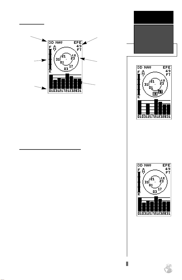
Satellite Page
R E F E R E N C E
Status
Battery
Indicator
Satellite
Number
Horizontal
Accuracy
Satellite
Sky View
Signal Strength
Indicators
The GPS 38 Satellite Page displays the status of various
receiver functions. The status information will help you
understand what the GPS is doing at any given time, and
tell you whether or not the receiver has calculated a position fix.
Sky View & Signal Strength Bars
The sky view and signal strength bars give you an indication of what satellites are visible to the receiver, whether
or not they are being used to calculate a position fix, and
the signal quality. The sky view in the center of the page
show’s a bird’s eye view of the position of each satellite relative to the receiver’s last known position. The outer circle
represents the horizon; the inner circle is 45º above the
horizon; and the center point is a position directly over
your head.
When the receiver is looking for a particular satellite,
the corresponding signal strength bar will be blank and the
sky view indicator will remain highlighted in reverse video.
Once the receiver has found the satellite, a hollow signal
strength bar will appear, indicating that the satellite has
been found and the receiver is collecting data from it. The
satellite number in the sky view will also change from
reverse video to normal presentation. As soon as the GPS
38 has collected the necessary data to use the satellite for
positioning, the hollow bar will become solid.
Satellite Page
Overview
Satellites in view but not
currently in use (03 & 17)
will be displayed in reverse
video, with the corresponding signal strength bar “hollow”.
Once a satellite in view is
usable for positioning, the
satellite number will change
from reverse video and the
signal strength bar will
become solid.
17
Page 22
R E F E R E N C E
Receiver Status
& EZinit
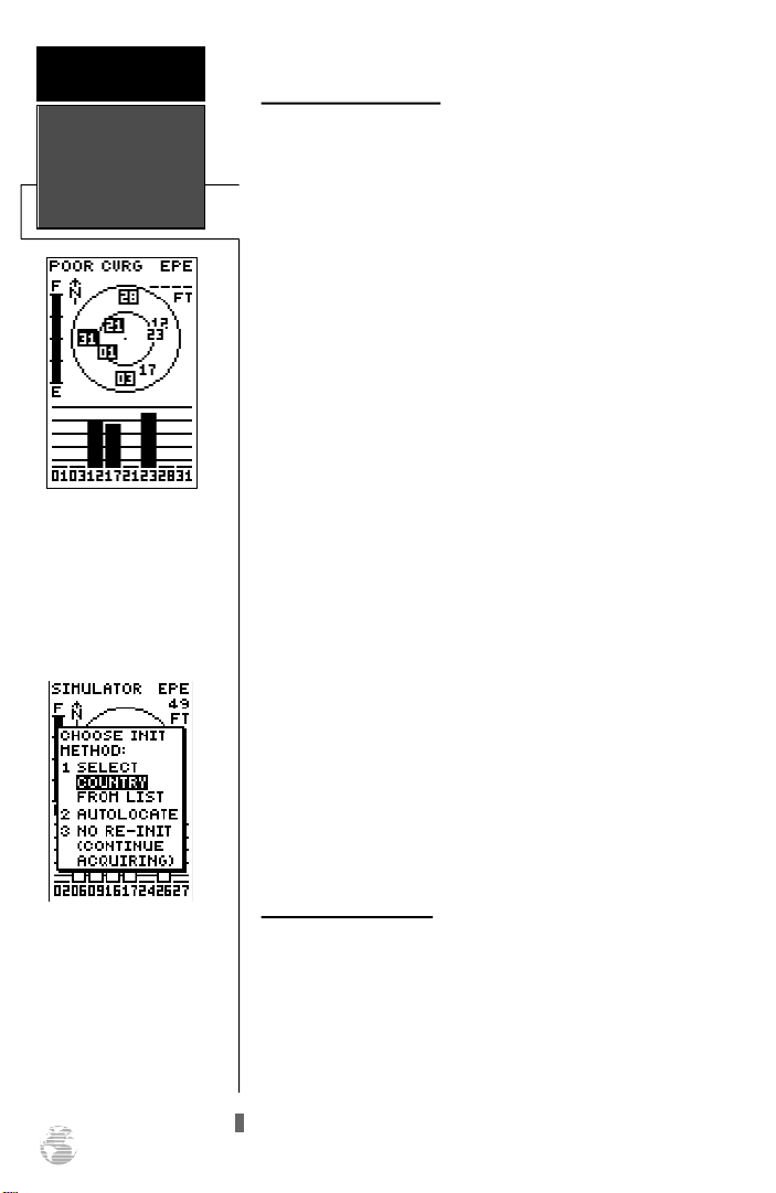
A ‘Poor Coverage’ status
will appear if the receiver
has lost the satellites
required to compute a fix.
Make s ure th e intern a l
antenna is not covered and
has a clear view of the sky.
Receiver Status & EPE
Receiver status is indicated at the top left of the screen,
with the current horizontal accuracy (estimated position
error, in feet or meters) at the top right. The status will
show one of the following conditions:
Searching— the GPS 38 is looking for any available
satellites in view.
AutoLocateTM— the GPS 38 is initializing and collect-
ing new almanac data. This process can take 7.5 to 15
minutes.
Acquiring— the receiver is collecting data from avail-
able satellites, but has not collected enough data to cal-
culate a 2D fix.
2D Nav (2D Navigation)— at least three satellites
with good geometry have been locked onto and a 2
dimensional position fix (latitude and longitude) is
being calculated. ‘2D Diff’ will appear when you are
receiving DGPS corrections in 2D mode.
3D Nav (3D Navigation)— at least four satellites with
good geometry have been locked onto and your posi-
tion is now being calculated in latitude, longitude and
altitude. ‘3D Diff’ will appear when you are receiving
DGPS corrections in 3D mode.
Poor CVG (Poor GPS Coverage)— the receiver is no
longer tracking enough satellites for a 2D or 3D fix.
Not Usable— the receiver is unusable, possibly due to
incorrect initialization or abnormal satellite conditions.
Turn the unit off and back on to reset.
Simulator (Simulating Navigation)— the receiver is
in simulator mode.
If you travel more than 300
miles with the receiver off,
you may have to reinitialize
the receiver to your new
location. To access the EZinit
prompt, press ENTER from
the Satellite Page before the
receiver has acquired any
satellites.
18
EZinit Option Prompt
The Satellite Page also provides access to the EZinit
prompt whenever a position fix has not been calculated
(the unit must be in searching, AutoLocate, acquiring, simulator or poor coverage mode). This allows you to manually
reinitialize the unit (see page 5-8 for instructions), and is
useful if you have traveled over 500 miles with the receiver
off and you know it must be initialized to your new position (the GPS 38 will automatically offer the
EZinit prompt after 10 minutes of unsuccessful satellite
acquisition).
Page 23
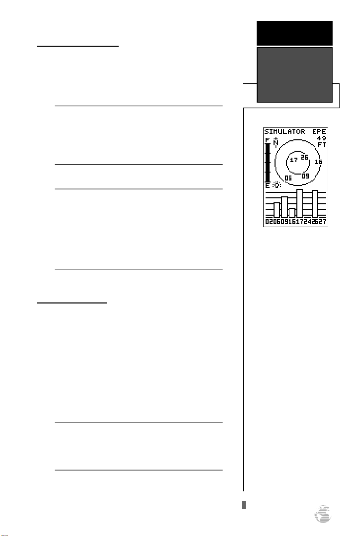
Battery Level Indicator
The Satellite Page also features a battery level indicator,
located below the status field to the left of the sky view,
which provides a graphic display of the condition of the
internal batteries.
The battery level indicator is calibrated for alkaline
!
#
batteries. Ni-Cad and lithium batteries will not
accurately display the battery level due to voltage
differences. No other receiver functions are affected by using Ni-Cad or lithium batteries.
It’s always best to store your GPS with the batteries
!
#
installed to preserve the internal memory and data.
The GPS 38 features a self-charging lithium battery
that continually maintains a full charge while batteries are installed. The lithium battery will maintain
the internal memory for 3 months in the event that
the batteries are removed or totally discharged.
Screen Backlighting
The GPS 38’s automatic backlight feature illuminates
the screen display for a user-defined interval (the default is
15 seconds) after every keystroke. When backlighting is on,
a bulb icon will appear at the bottom left of the sky view.
To turn the screen backlighting on or off:
R E F E R E N C E
Battery Level &
Backlighting
A bulb icon will appear on
the Satellite Page whenever
the screen backlighting is
on. The backlight will turn
on for the time selected after
every keystroke.
1. Press the Bkey.
2. To adjust the duration of screen backlighting, refer to the
operation setup section (page 46).
Using the screen backlighting can greatly affect
!
battery life. If you’re using your GPS primarily in
#
daylight hours, you should keep the backlight timeout at the default 15 second setting.
19
Page 24
R E F E R E N C E
Position Page
The speed displayed on the
Position Page may fluctuate
at slow speeds (or when
y o u ’ re standing still)
because of position errors
caused by Selective
Availability.
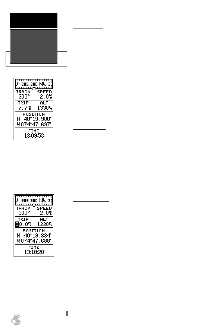
Position Page
The GPS 38’s Position Page shows you where you are,
what direction you’re heading and how fast you are going
(up to 99.9 mph), and is most useful when you are traveling without an active destination waypoint. A graphic compass tape at the top of the page displays your cardinal heading (while you’re moving), with your current track and
speed over the ground indicated below. The rest of the page
shows your present position in three dimensions (latitude,
longitude and altitude). The units of measure for speed,
distance, position and altitude are all user-selectable
through the navigation setup menu (see page 48). The
12/24 hour clock and time offset options are available from
the system setup menu (see page 46).
Trip Odometer
The Position Page also features a resettable trip odometer to measure the total distance traveled while navigating.
To reset the trip odometer:
1. Highlight the ‘TRIP’ field.
2. Press E, followed by L.
3. Press Eto finish.
To reset the trip odometer,
highlight the trip field and
p ress ENTER. Use the
LEFT arrow key to clear the
distance field and pre s s
ENTER to confirm.
20
Altitude Display
When the GPS 38 is acquiring satellites or navigating in
the 2D mode, the last known altitude will be used to compute your position. If the altitude shown is off by several
hundred feet, you can manually enter your altitude for
greater accuracy. Note that GPS altitudes can fluxuate due
to errors.
1. Highlight the ‘ALT’ field.
2. Press Eto begin entry of your altitude.
3. Enter a value in each character field.
4. Press the Ekey to confirm the altitude.
Page 25
Marking And Saving Waypoints
Knowing your present position is only part of any navigation equation. You also need to keep track of where
you’ve been and where you are going. Waypoints serve as
electronic markers that let you keep track of starting points,
destinations, navaids and any other important position.
The GPS 38 allows you to mark, store and use up to
250 waypoints. A waypoint position can be entered by taking an instant electronic fix or by manually entering a coordinate or range and bearing in reference to an existing waypoint. If you try to mark a waypoint without having a position fix, you’ll be notified with a ‘No GPS Position’ message.
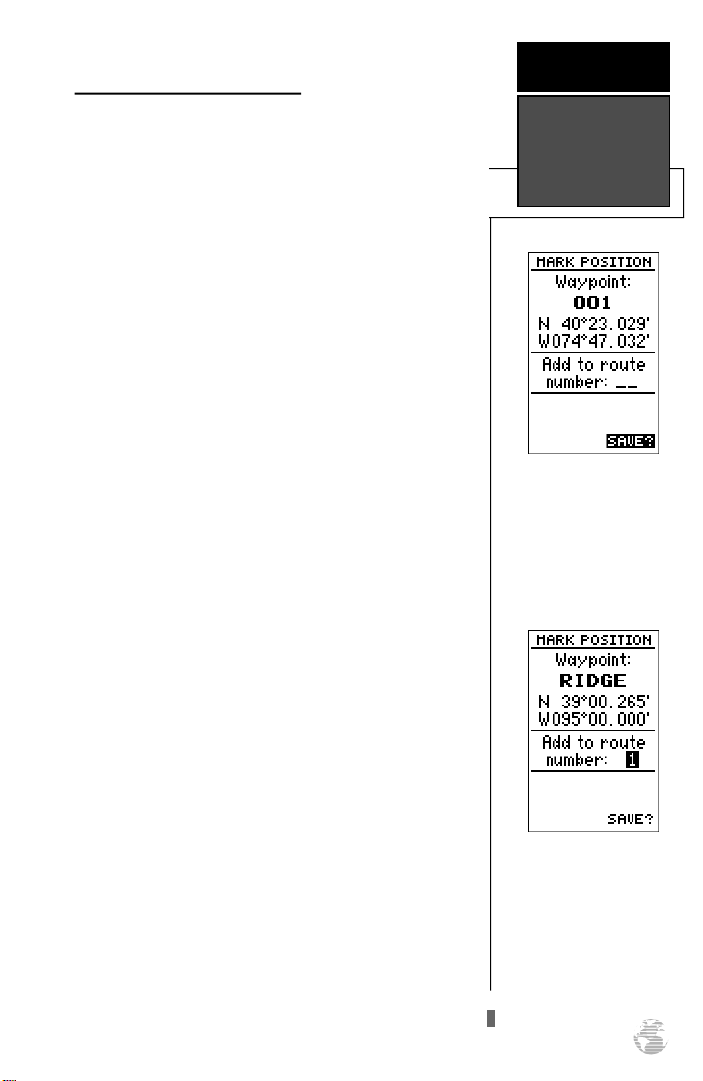
To mark your present position:
1. Press the Mkey to capture your position.
The mark Position Page will appear, showing the captured position and a default 3-digit waypoint name.
To change the default position name :
1. Highlight the ‘Waypoint’ field.
2. Press Ekey to begin entry of the name. Pressing the
key will clear any existing data.
L
3. Use the arrow keypad to enter a waypoint name.
R E F E R E N C E
Marking &
Saving
Waypoints
The GPS 38 will save new
waypoints with a default
three-digit name.
4. Press Eto confirm the waypoint name. The field high-
light will move to the route field.
If you’d like to add this waypoint to a route:
1. Press the Ekey.
2. Enter a route number.
3. Press the Ekey to confirm the route number.
4. Press the Ekey again to save the waypoint.
If you do not want to add this waypoint to a route:
1. Highlight the ‘SAVE?’ field and press the Ekey.
You may add a new waypoint to the end of any storage route by entering the
desired route number in the
route field before saving the
waypoint.
21
Page 26
R E F E R E N C E
Nearest
Waypoints Page
To select a waypoint submenu, highlight the desired
option and press ENTER.
Waypoint Submenus
The GPS 38 has three waypoint submenu Pages that let
you manage a large number of waypoints quickly and efficiently. The nearest waypoints, waypoint list and waypoint
definition pages are accessed through the Menu Page.
To select a waypoint submenu page:
1. Press Por Quntil the Menu Page appears.
2. Highlight the waypoint submenu page you want to use.
3. Press Eto display the submenu page.
4. To return to the Menu Page, press the Pkey.
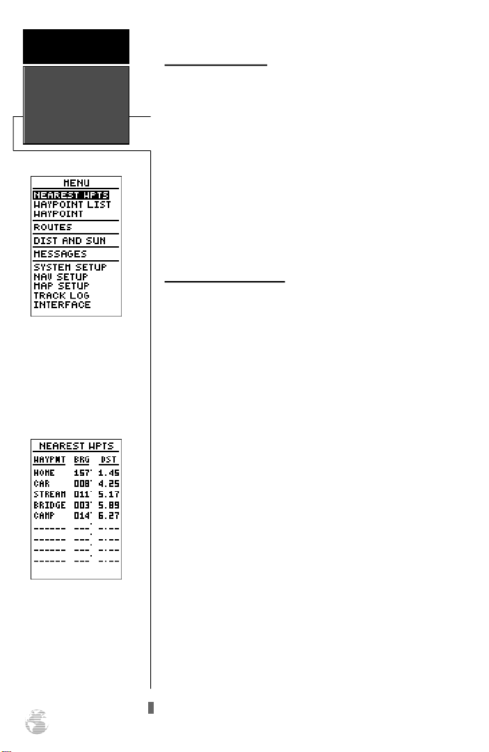
Nearest Waypoints Page
The nearest waypoints page shows the nine nearest
waypoints that are within 100 miles of your present position, with the bearing and range noted for each waypoint.
During an emergency, the nearest waypoints page can give
you the closest points of safety in your area at a glance.
The nearest waypoints page will also let you retrieve a
waypoint definition page or GOTO a selected waypoint
right from the list.
To review the waypoint definition page of a highlight-
ed waypoint from the list:
Nearest Waypoints Page
The compass heading (BRG)
and distance (DST) to the
nine nearest waypoints are
updated continuously.
22
1. Press the Ekey.
To return to the nearest waypoint page (when the
‘Done?’ field is highlighted):
1. Press the Ekey.
To go to a highlighted list waypoint:
1. Highlight a listed waypoint.
2. To select a highlighted nearest waypoint as a destination,
press the Gkey.
3. Once the GOTOwaypoint page appears, press the
key to confirm the selected waypoint as your destination.
E
Page 27
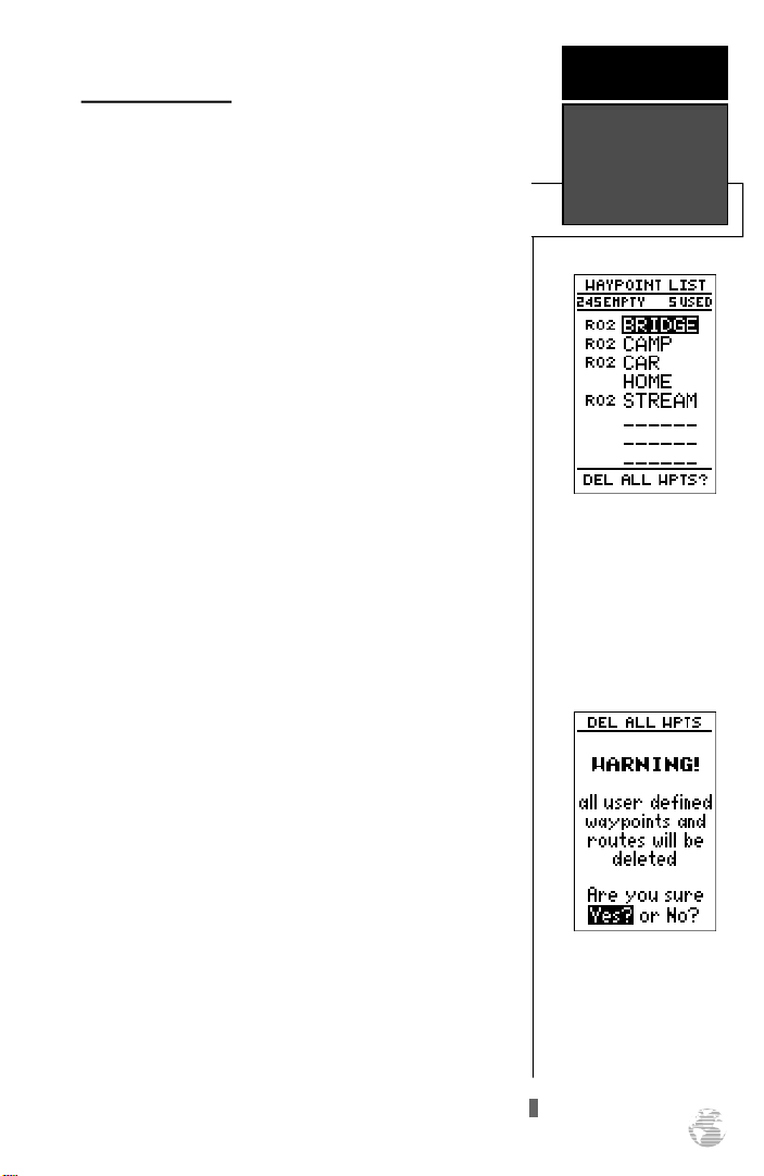
Waypoint List Page
The waypoint list page provides you with a complete
list of all waypoints currently stored in the GPS 38. The
total number of used and free waypoints is indicated above
the waypoint list. From the waypoint list page, you can
retrieve a waypoint definition page or delete all userdefined waypoints, or go to a selected waypoint. If a waypoint is currently used in a route, the lowest route number
will be indicated to the left of the waypoint name.
To review the waypoint definition page of a highlight-
ed list waypoint:
1. Press the Ekey.
To return to the waypoint list page (with the ‘Done?’
field highlighted):
1. Press the Ekey.
To go to a list waypoint:
1. Scroll through the list and select a waypoint.
2. To select a highlighted waypoint as a destination, press
the Gkey.
3. Once the GOTOwaypoint page appears, press the
key to confirm the selected waypoint as your destination.
E
To delete all user defined waypoints:
R E F E R E N C E
Waypoint List
Page
Waypoint List Page
The total number of used
and available waypoints is
indicated at the top of the
page. Waypoints that are
part of a route are indicated
by, a ‘R__’. Above, ‘RO2‘
means route 2.
1. Move the cursor highlight to ‘DEL ALL WPTS’.
2. Press the Ekey.
A warning page will appear, asking if you are sure you
want to delete all user-defined waypoints and routes. If you
want to continue and delete:
1. Highlight the ‘Yes?’ field.
2. Press the Ekey.
3. Press the Qkey to return to the Menu Page.
If you do not want to delete all waypoints:
1. Highlight the ‘No?’ field and press E.
Deleting all user waypoints
will also delete all routes
stored in memory.
23
Page 28
R E F E R E N C E
Waypoint
Definition Page
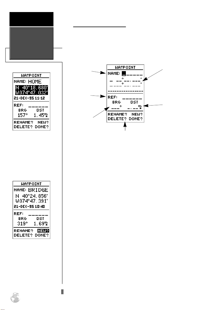
Waypoint Definition Page
The last of the three waypoint management pages is the
waypoint definition page. This page lets you create new
waypoints manually, as well as review and edit existing
waypoints.
Waypoint
Definition Page
Use the waypoint definition
page to review, rename or
delete stored waypoints and
to create new waypoints
manually.
To create a new waypoint by
manually entering coord inates or by referencing an
existing waypoint, highlight
the NEW? prompt and press
the ENTER key.
Waypoint
Name
Reference
Waypoint
Bearing from
Reference
Waypoint
Function Prompts
Position
Coordinates
Distance from
Reference
Waypoint
To create a new waypoint manually, you’ll need to know
its position coordinates or its distance and bearing from an
existing waypoint.
To create a waypoint by entering coordinates:
1. Highlight the ‘NEW?’ field.
2. Press E.
3.Enter your waypoint name and press Eto confirm. The
position field will now become highlighted, with the receiver’s last known position shown.
4. Press Eto begin entry of the position.
5. When finished, press Eto confirm and save your
coordinates. The default waypoint comment (UTC date and
time of creation) will appear and the highlight will move to
the ‘DONE?’ field.
6. Press the Ekey to return to the Menu Page.
24
Page 29
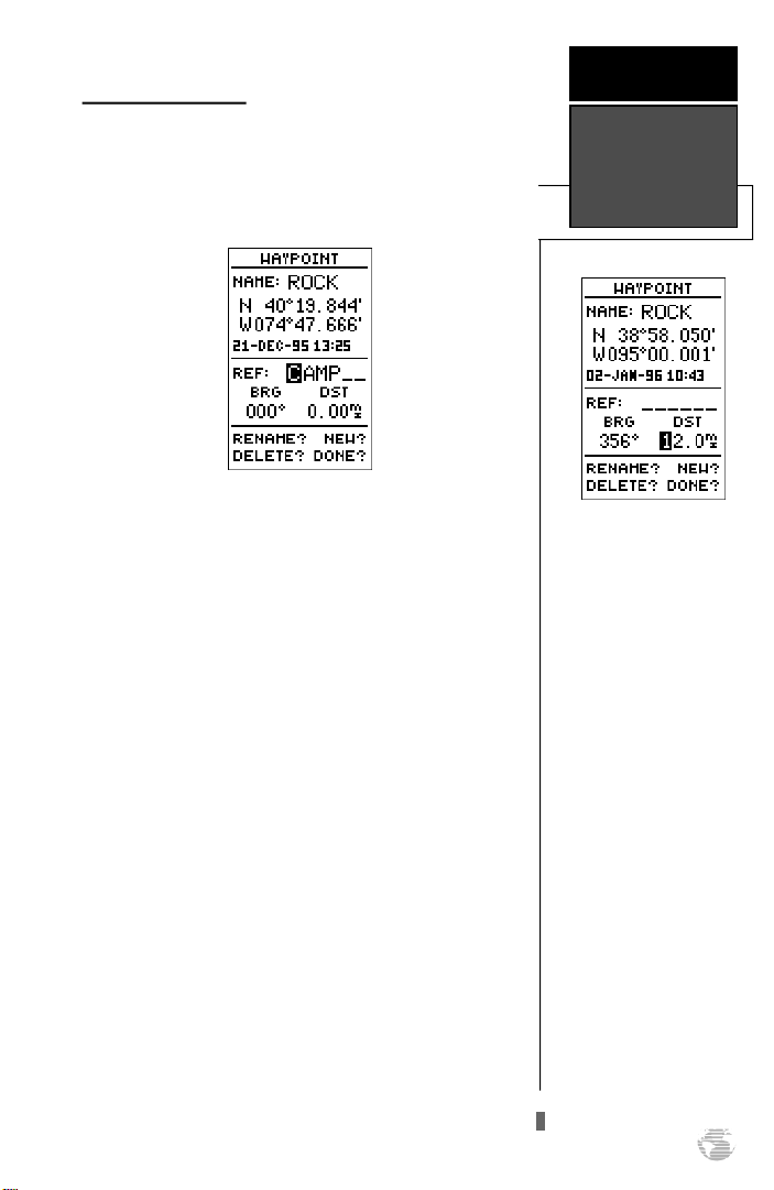
Reference Waypoints
To create a new waypoint manually without knowing its
position coordinates, you’ll need to enter its bearing and
distance from an existing waypoint. The GPS 38 will then
calculate the position coordinates for you.
R E F E R E N C E
Reference
Waypoints
To create a new waypoint by referencing a stored
waypoint:
1. Highlight the ‘NEW?’ field.
2. Press E.
3. Enter the name of your new waypoint.
4. Press the Ekey to confirm the waypoint name.
The position field will now become highlighted, with the
receiver’s last known position shown.
5. Move the cursor to the reference field.
6. Press Eto begin entry of reference waypoint.
7. Use the arrow keypad to enter the waypoint name.
8. Press the Ekey to confirm your entry.
9. Enter the bearing and distance of your new waypoint from
the reference waypoint. Remember to use the Ekey
to begin entry and confirm each field. The coordinates will
be calculated and saved for your new waypoint.
10. Highlight the ‘DONE?’ field and press Eto return to
the Menu Page.
The GPS 38’s advanced
waypoint and planning features allow you to create
new waypoints and practice
navigation without ever
stepping foot outside.
If you create a new waypoint by entering coord inates from a map, you may
want to remark the waypoint’s exact position once
you get there.
To redefine an existing waypoint’s position coordinates
from the waypoint definition page, simply highlight
the DST field and pre s s
ENTER. Use the LEFT
arrow key to set the distance
to 0.00, and press ENTER
to confirm.
The old coordinates will be
replaced by the coordinates
of your present position
(you must have a valid 2D
or 3D position fix).
25
Page 30
R E F E R E N C E
Editing,Deleting
& Renaming
Waypoints
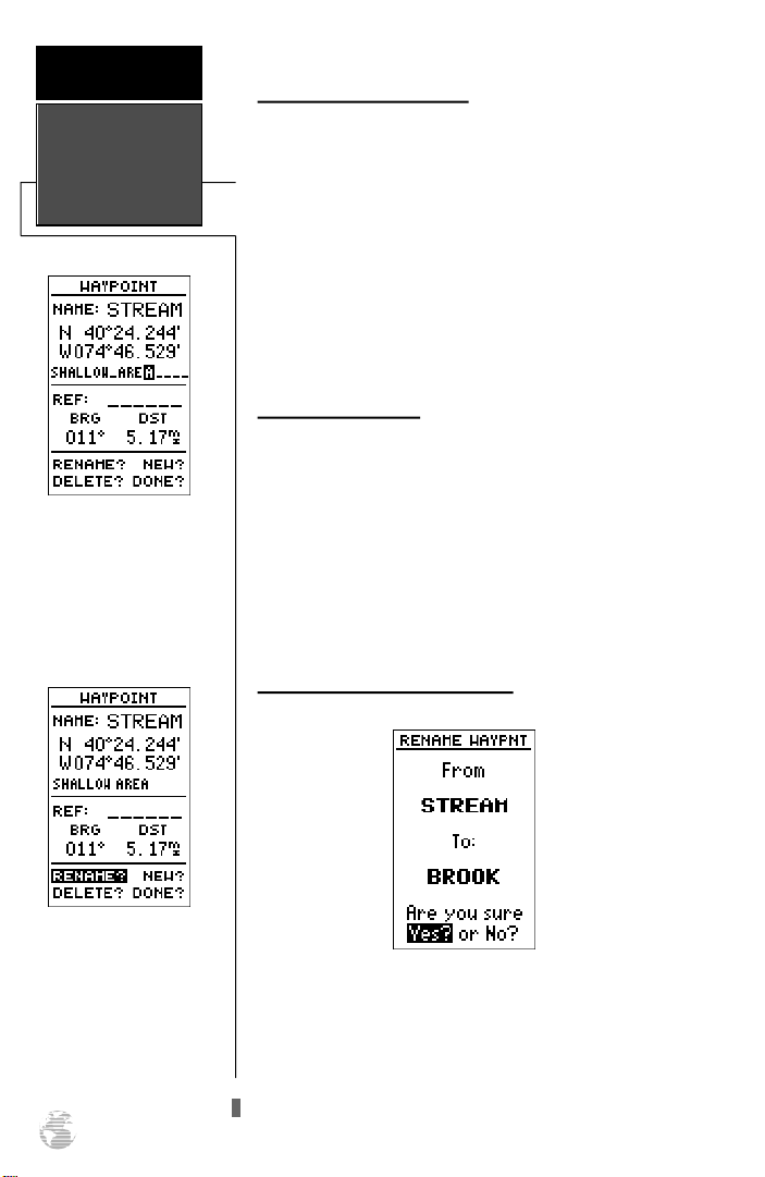
The waypoint comments
field will automatically
assign the date and time of
c reation to the waypoint
comments field. You may
enter a 16-character user
comment at any time.
Editing Existing Waypoints
The waypoint definition page also allows you to review
and change a stored waypoint’s name, coordinates, comment or reference waypoint at any time.
To edit waypoint coordinates or a reference waypoint:
1. Highlight the field you want to edit.
2. Press Eto begin entry in the selected field.
3. Enter your new data.
4. Press the Ekey to confirm your changes.
Waypoint Comments
Each waypoint stored in the GPS 38 has a user-defined
16 character comment field. The default comment is the
UTC date and time of the waypoint’s creation.
To change or add a comment:
1. Highlight the comment field.
2. Press Eto begin entry of your comment.
3. Enter the comment and press the Ekey to confirm.
Renaming & Deleting Waypoints
To access the rename function from the waypoint
definition page, highlight
the ‘RENAME?’prompt and
press ENTER.
26
The rename and delete function fields are located at the
bottom left of the waypoint definition page (you’ll need to
use the Lkey to move the highlightout of its main
scrollingsequence).
Page 31
To rename a stored waypoint:
R E F E R E N C E
1. Highlight the ‘RENAME?’ field and press E.
2. Enter the new waypoint name and press E.
3. Press the Ekey to confirm your changes.
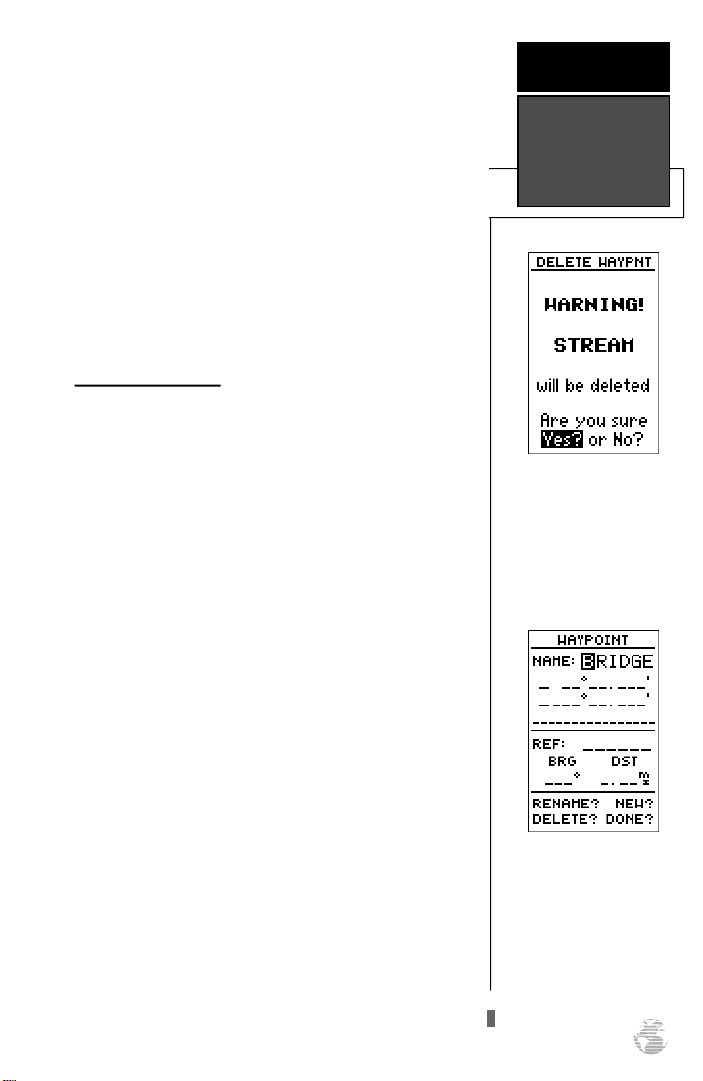
To delete a stored waypoint:
1. Highlight the ‘DELETE?’ field and press E.
2. Select the ‘Yes?’ prompt.
3. Press Eto delete the waypoint.
Scanning Waypoints
As you manually enter a waypoint’s name, the GPS38’s
waypoint scanning feature will automatically display the
first numerical or alphabetical match of the character you
have entered to that point. This helps eliminate the need to
always enter a waypoint’s complete name.
To scan waypoints from a waypoint field:
1. Highlight the waypoint name field and press E.
2. Press the Lkey to clear the name field.
3. Use the arrow keypad to scroll through the waypoints.
4. If you have more than one waypoint that begins with the
same letter or number, you must use the Rkey to move to
the next character positions as needed. Only the first character match is listed for each character set.
Editing &
Scanning
Waypoints
To delete a waypoint, conf i rm the ‘Yes?’ pro m p t .
Route or active waypoints
may not be deleted until
they are removed from the
route or the GOTO h a s
been cancelled.
5. Once you’ve found the desired waypoint, press E.
The waypoint scanning feature will offer the first waypoint that matches the character or characters you
have entered to that point.
27
Page 32
R E F E R E N C E
Starting/Stopping
a GOTO & MOB
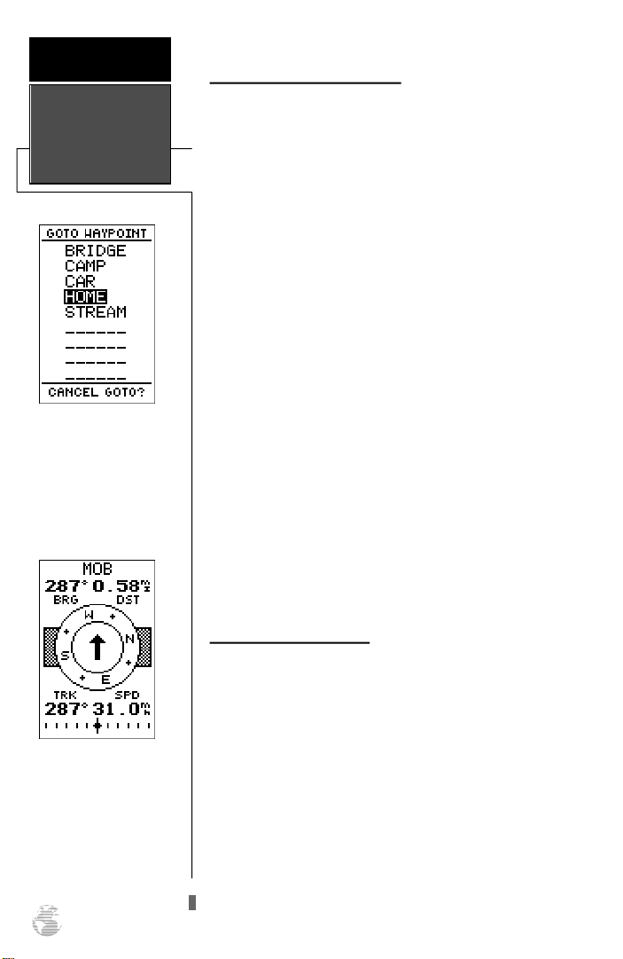
Select a destination waypoint from the GOTO waypoint list.
Selecting a GOTO Destination
The GPS 38 provides four ways to navigate to a destination: GOTO, MOB, TracBack and route navigation. The
most basic method of selecting a destination is the GOTO
function, which lets you choose any stored waypoint as the
destination and quickly sets a direct course from your present position.
To activate the GOTO function:
1. Press the Gkey. The GOTO waypoint list, an alphabetical list of all available waypoints, will appear.
2. Select the waypoint you want to navigate to (it may
already be highlighted).
3. Press the Ekey to confirm, or Qto stop selection
of a GOTO destination and return to the previous page.
Once a GOTO waypoint has been activated, the
Compass Page or Highway Page will provide steering guidance to the destination until the GOTO is cancelled, or the
unit has resumed navigating the active route (see page 36).
To cancel an active GOTO:
1. Press the Gkey.
2. Move the field highlight to the ‘CANCELGOTO?’ prompt at
the bottom of the page.
Once the MOB mode has
been activated , steering
guidance will be provided by
the Compass or Highway
Page. Activating another
MOB will overwrite the previous MOB waypoint.
28
3. Press
E
Man Overboard Function
The GPS 38’s man overboard function (MOB) lets you
simultaneously mark and set a course to a position for
quick response to passing positions (like the spot where
your hat blew overboard).
To activate the MOB mode:
1. Press the Gkey twice. The GOTO waypoint page will
appear with ‘MOB’ selected as the default destination.
2. Press the Ekey to begin MOB navigation.
The GPS 38 will now guide you to the MOB waypoint
until the MOB GOTO is cancelled (see page 28). If you
want to save the MOB waypoint, be sure to rename it, as it
will be overwritten the next time a MOB is executed.
Page 33
TracBack Navigation
The third method of navigating to a destination is by
using the GPS 38’s TracBack feature. The TracBack function
allows you to quickly and easily retrace your path using the
track log automatically stored in the receiver’s memory. The
advantage of the TracBack feature is to eliminate the need
to mark waypoints along the way and manually create and
activate a route back to where you began your trip.
The TracBack route is created by reducing your current
track log into a route of up to 30 waypoints, and activating
an inverted route along those points. Once activated, a
TracBack route will lead you back to the oldest track log
point stored in memory, so it’s usually a good idea to clear
the existing track log at the starting point of your current
trip (e. g. the trail head or your car) before you get started.
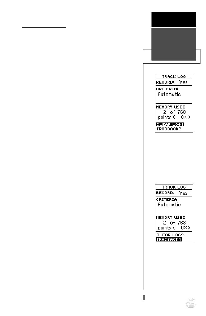
To clear the track log and define a starting point for
a TracBack route:
1. From the Menu Page, highlight the ‘TRACKLOG’ option.
2. Press Eto access the track log page.
3. Highlight the ‘CLEARLOG?’ option.
4. Press E. The clear log confirmation page will appear.
5. Highlight the ‘Yes?’ prompt and press E.
To activate a TracBack route:
R E F E R E N C E
TracBack
Navigation
Clearing the log before you
get started will define the
position the TracBack function will return you to.
1. From the Menu Page, highlight the ‘TRACKLOG’ option.
2. Press Eto access the track log page.
3. Highlight the ‘TRACBACK?’ option and press E.
Once the TracBack function has been activated, the GPS
38 will take the track log currently stored in memory and
divide it into segments called legs. Up to 30 temporary
waypoints (e.g., ‘T001’) will be created to mark the most
significant features of the track log to duplicate your exact
path as closely as possible. A TracBack route from your present position to the oldest track log point will be created as
the active route (the active route page will appear), and
provide steering guidance to each waypoint back to the
starting point of your track log.
Highlight the ‘Tr a c B a c k ’
prompt and press ENTER to
begin TracBack navigation.
An on-screen status box will
monitor the progress of the
TracBack calculation.
29
Page 34
R E F E R E N C E
TracBack
Navigation
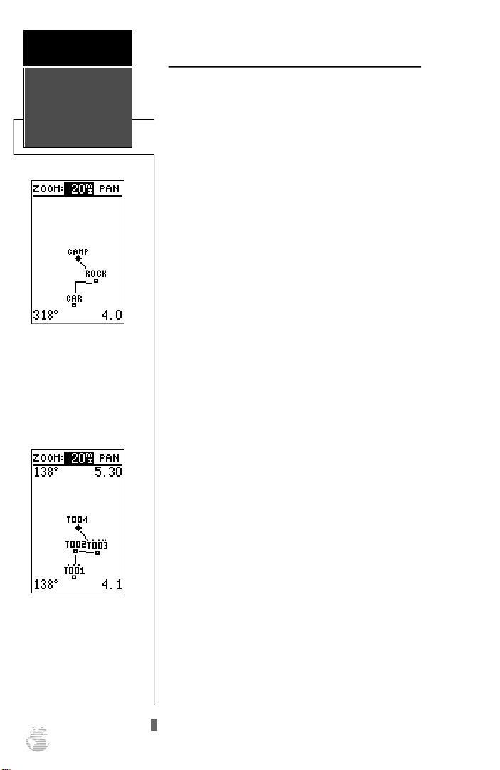
The TracBack feature will
navigate your track log back
to the oldest point in the
receiver’s memory.
The track log will be divided
into segments with tempor a ry waypoints to create
a route back to the begin-
ning of the track log.
30
Tips on Creating and Using the TracBack Feature
The GPS 38’s TracBack feature is designed to help you
quickly create and activate a route that follows your path
back to a user-defined starting point. To get the most out of
the TracBack feature, remember the following tips:
• Always clear your track log at the exact point that you
want to go back to (trail head, truck dock, etc.).
• The ‘RECORD’ option on the track log setup page
must be set to the ‘Yes’ position.
• There must be at least two track log points stored in
memory to create a TracBack route.
• If there are not enough available waypoints in memo-
ry to create a TracBack route, you will be alerted with
a ‘waypoint memory full’ message, and the receiver
will use any available waypoints to create a TracBack
route with an emphasis on the track log closest to the
destination (the oldest track log point in memory).
• If the ‘CRITERIA’ option on the track log setup page is
set to a time interval, the TracBack route may not follow your exact path (keeping the criteria set to automatic will always provide the best TracBack route).
• If the receiver is turned off or you lose satellite cover-
age during your trip, the TracBack route will simply
draw a straight line between any point where coverage was lost and where it resumed.
• If the changes of direction and distance of your track
log are very complex, 30 waypoints may not be
enough to accurately mark your exact path. The
receiver will then assign the 30 waypoints to the most
significant points of your track, and simplify segments
with fewer changes in direction.
• If you want to save a TracBack route, copy route 0 to
an open storage route before activating another
TracBack. Activating another TracBack or storage
route will overwrite the existing TracBack route.
• Whenever a TracBack route is activated, the receiver
will automatically erase any temporary waypoints
(e.g., ‘T001’) that are not contained in routes 1-19. If
there are temporary waypoints stored in routes 1-19,
the receiver will create any new temporary waypoints
using the first three digit number available.
Page 35
Creating and Navigating Routes
The last form of navigating to a destination with the
GPS 38 is by creating a user-defined route. The route navigation feature lets you plan and navigate a course from one
place to another using a set of pre-defined waypoints.
Routes are often used when it’s not practical, safe or possible to navigate a direct course to a particular destination
(e.g., through a body of water or impassable terrain).
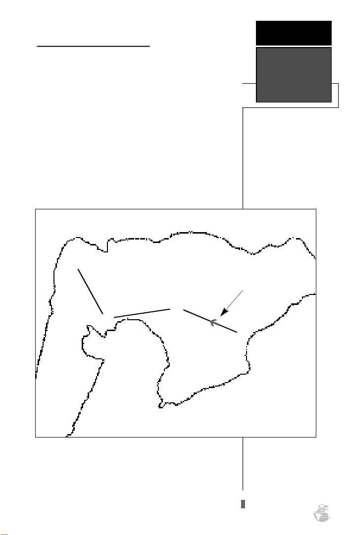
Routes are broken down and navigated in smaller segments called “legs”. The waypoint you are going to in a leg
is called the “active to” waypoint, and the waypoint immediately behind you is called the “active from” waypoint. The
line between the “active to” and the “active from” waypoint
is called the “active leg”.
ä
Waypoint 2
(“active to” waypoint)
“Active Leg”
ä
ä
©
(“active from” waypoint)
R E F E R E N C E
Route
Navigation
Waypoint 1
Whenever you activate a route with the GPS 38, it will
automatically select the route leg closest to your position as
the active leg. As you pass each waypoint in the route, the
receiver will automatically sequence and select the next
waypoint as the “active to” waypoint.
31
Page 36
R E F E R E N C E
Creating A
Route
Route Definition Page
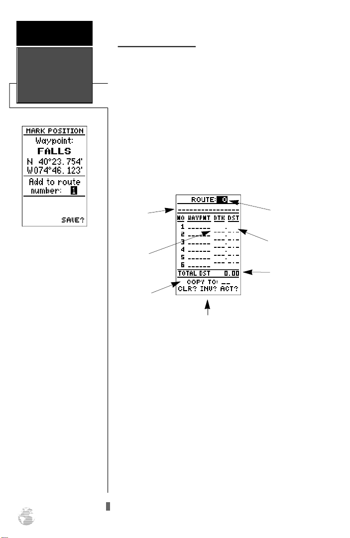
The GPS 38 lets you create and store up to 20 routes of
30 waypoints each. Routes are created, copied, and edited
through the route definition page, which is accessed
through the Menu Page.
To select the route definition page:
1. Press Puntil the Menu Page appears.
2. Highlight the ‘ROUTES’ option.
3. Press the Ekey to display the route definition page.
4. To return to the Menu Page, press P.
If you’re heading out without a planned route, the
mark function can be used
to quickly create a ro u t e
back to your starting point.
Create a series of waypoints
along the way with the
MARK key and save them
to an open route from the
mark position page. When
you’re ready to head back,
simply activate the ro u t e
you created in in vert e d
order (see page 34).
32
Comment
Field
Desired
Track of Leg
Copy Field
Function Prompts
Route
Number
Leg Distance
Total
Distance
The route number field is displayed at the top of the
page, with a 16-character user comment below. If no user
comment is entered, the field will display the first and last
waypoint in the route. The waypoint list in the middle of
the page accepts up to 30 waypoints for each route, with
fields for desired track and distance between waypoints.
The total distance of the route is indicated below the waypoint list.
The bottom of the route definition page features several
function fields which let you copy, clear, invert, or activate
the displayed route. Routes 1-19 are used as storage routes,
with route 0 always serving as the active route you are navigating. If you want to save a route currently in route 0, be
sure to copy it to another open route, as it will be overwritten by the next route activation.
Page 37
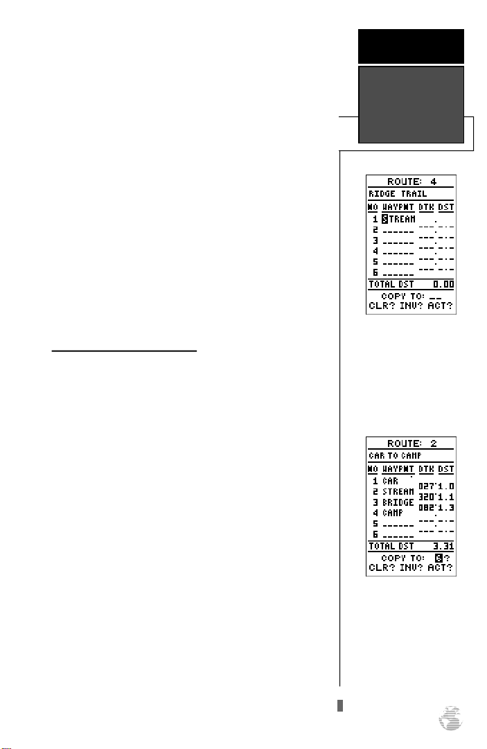
To create a route from the route definition page:
R E F E R E N C E
1. Highlight the route number field and press E.
2. Enter a route number and press the Ekey to confirm.
3. Press Eto begin entry of a route comment. (Note that
the default (first and last waypoint) comment will only
appear if the comment field is blank).
4. Enter your comment and press the Ekey.
5. Highlight the No. 1 waypoint field and press E.
6. Enter the first waypoint of your route and press E.
7. Continue entering the rest of your waypoints in order,
using the Ekey to start and confirm each field entry.
The list will automatically scroll down as needed.
8. After you have entered all your waypoints, press P.
Copying and Clearing Routes
The route definition page is also used to copy a route to
another route number. This feature is useful when you
make changes to the active (or TracBack) route and want to
save the route for future use.
To copy a route:
1. Highlight the route number field and press E.
2. Enter the route number to be copied and press E.
Creating,
Copying &
Clearing Routes
Enter each waypoint in the
order you would like to navigate them. If you enter a
waypoint not stored in
m e m o ry, you’ll need to
define the position on the
waypoint definition page.
3. Highlight the ‘COPYTO’ field and press E.
4. Scroll through the available routes and select a destination
route number. Only open routes will be available as choices. Press the Ekey to copy the route.
5. Press the Pkey to return to the Menu Page.
To clear a route from memory:
1. Highlight the route number field and press E.
2. Enter the route number and press E.
3. Select the ‘CLR?’ prompt and press E.
To copy a route, select an
open storage route and
press the ENTER key. If you
select a route that is already
used, you’ll be alerted with
an ‘Route Full’ message.
33
Page 38
R E F E R E N C E
Clearing,
Activating &
Inverting Routes
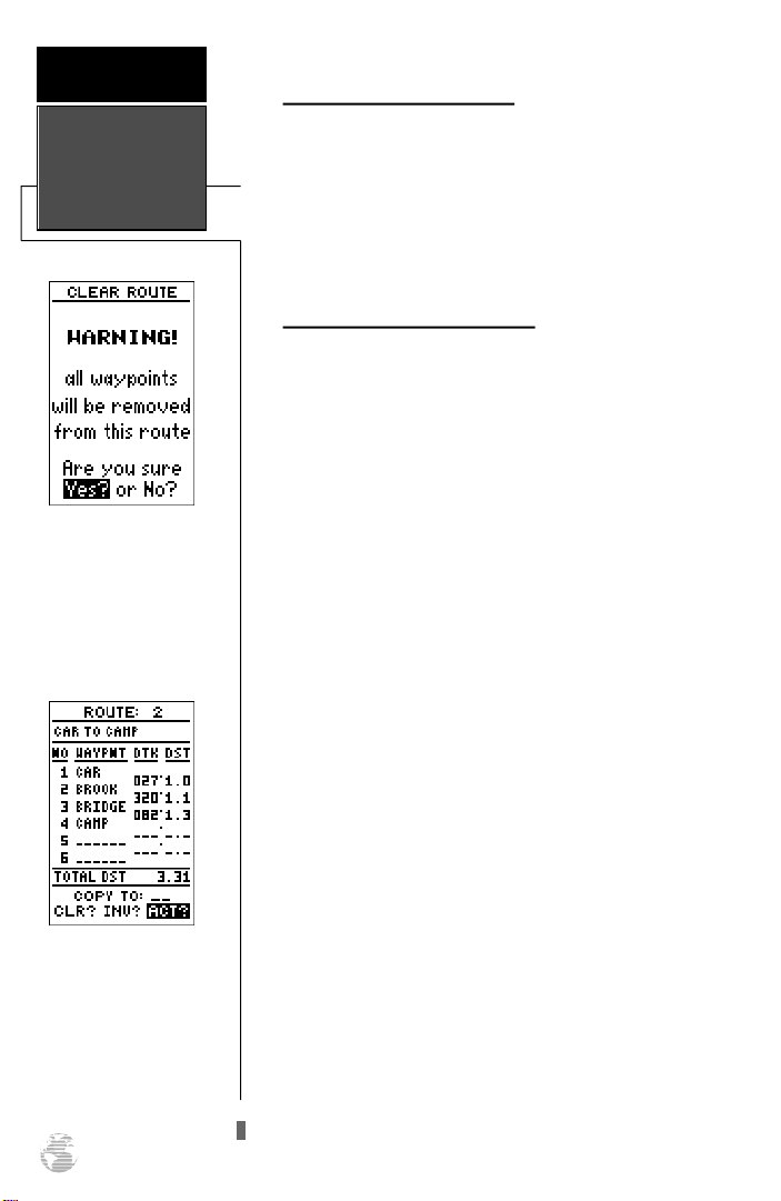
Clearing a route only
removes the waypoints from
the route selected. The way-
points used will remain in
the receiver’s memory.
Clearing a Route (continued)
The clear route warning will appear, asking you to con-
firm that you want to remove all waypoints from the route.
1. Highlight the ‘Yes?’ selection.
2. Press Eto confirm your action.
3. Press Pto return to the Menu Page.
Activating and Inverting Routes
After a route has been entered, it can be activated in its
defined sequence or inverted from the route definition
page. The process of activating or inverting a stored route
takes a storage route (routes 1-19) and copies it into the
active route (route 0) for navigation. The storage route is
now no longer needed and will be retained in its original
format under its existing route number.
This system allows you to have an active route that you
may edit during navigation and save as an entirely new
route from the original. You will have to copy the active
route to an unused storage route to save it, since new route
or TracBack activation overwrites route 0.
To activate a route:
1. Select the route definition page and press the Ekey
to activate the route number field.
To activate a route, highlight the ‘ACT?’ prompt and
press ENTER.
34
2. Enter the route number to be activated and press E.
3. Move the field highlight to the ‘ACT?’ prompt and press
the Ekey.
Inverting a route allows you to navigate route legs in
reverse order, without editing the original route.
To activate a route in inverted order:
1. Follow the steps above, but select the ‘INV?’ prompt and
press E.
Page 39
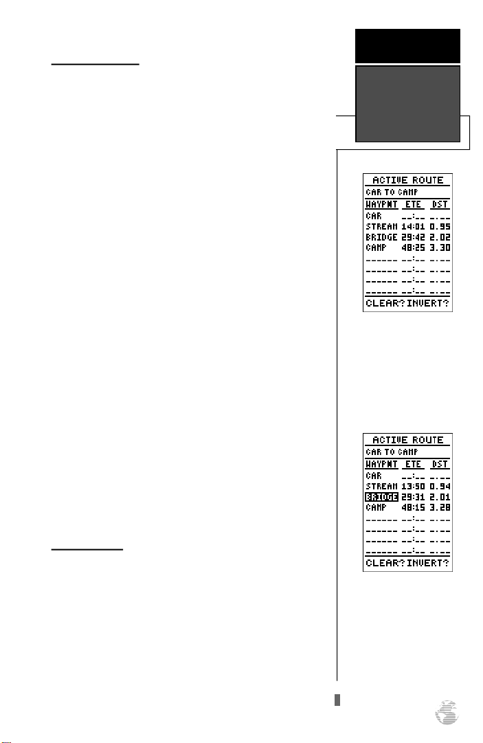
Active Route Page
R E F E R E N C E
Once a route has been activated, the active route page
will appear, displaying the waypoint sequence of your route
with the estimated time enroute (ETE) at your present
speed and distance to each waypoint. As long as you are
navigating an active route, the active route page will
become part of the main page sequence of the unit.
The active route page will also allow you to change the
ETE field to display desired track (DTK) or estimated time
of arrival (ETA) for each leg. You can also clear or invert the
active route.
To display DTK or ETA for each leg:
1. Highlight the estimated time enroute (ETE) field and press
the Ekey.
2. Select ‘DTK’ or ‘ETA’ and press the Ekey.
The active route page also allows you to clear (stop navigating) or invert the active route without using the route
definition page.
To invert a route from the active route page:
1. Move the field highlight to the ‘INVERT?’ prompt.
2. Press the Ekey to invert the route.
To clear the active route from the active route page
and stop route navigation:
Active Route
Page
Active Route Page
Whenever you have an
active route, the active route
page will appear in the
main page sequence after
the Compass/Highway
Page.
1. Select the ‘CLEAR?’ prompt.
2. Press the Ekey to clear the active route.
Editing Routes
Once a route has been created and stored, it can be
edited at any time, even if it is the active route.
To edit a route from the active route page or the route
definition page:
1. Select the waypoint you want to edit and press E.
To edit or review a route
waypoint from the active
route page, highlight the
desired waypoint and press
ENTER.
35
Page 40
R E F E R E N C E
Editing Routes
& On-Route
GOTOs
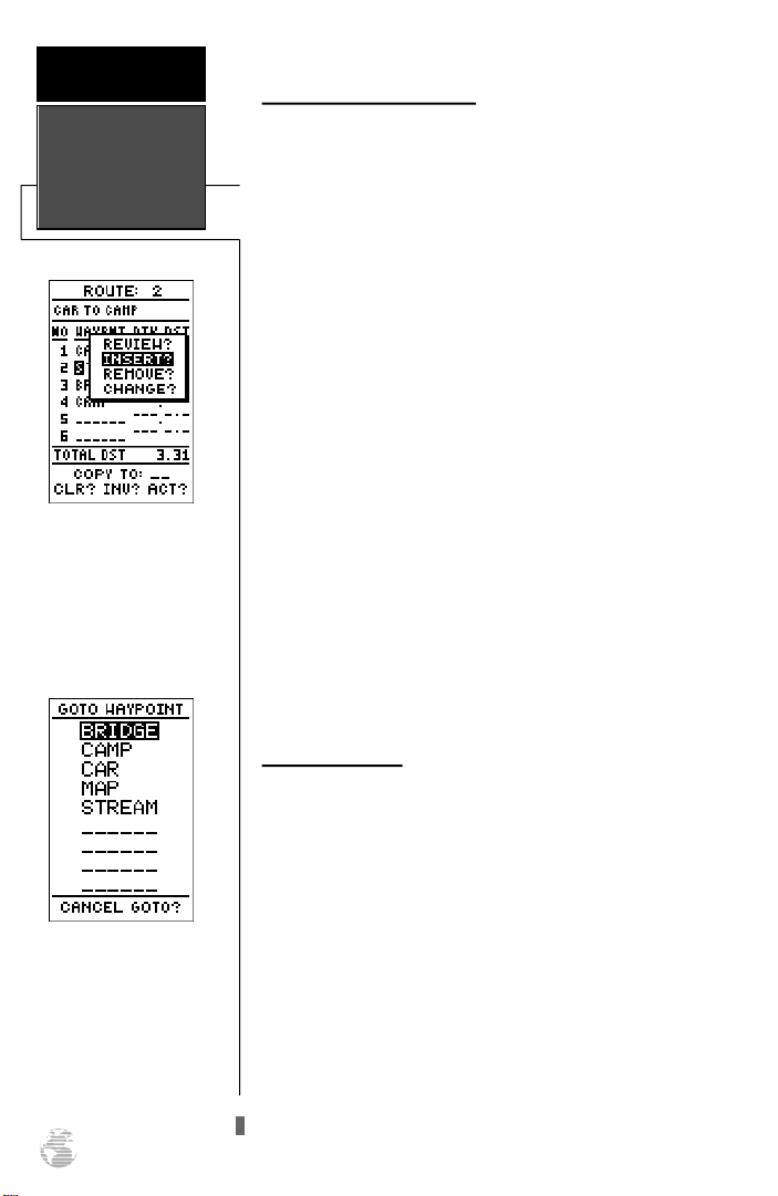
Use the on-screen menu to
select the desired editing
function.
Editing Routes (continued)
An on-screen menu of editing choices will appear, with
options for reviewing, inserting, deleting or changing the
waypoint field highlighted. Use the Uand Darrow
keys to select among the editing choices.
Once you’ve selected a waypoint from the route list,
choose a menu function:
1. To review the definition page for the waypoint, highlight
the ‘REVIEW?’ prompt and press E.
2. To add a new waypoint that precedes the selected waypoint, highlight the ‘INSERT?’ prompt and press E.
3. To remove the selected waypoint, highlight the ‘REMOVE?’
prompt and press the Ekey.
4. To replace the selected waypoint with a new waypoint,
highlight the ‘CHANGE?’ prompt and press the Ekey.
Use the route waypoint editing instructions described
earlier for creating a route to complete your changes. If you
are editing the active route (route 0), copy your new route
version to an empty route to save it, as the active route will
be overwritten by a new route activation.
If you add, delete or change the first or last waypoint of
a route, the default comment (first and last waypoint) will
automatically be updated after your changes.
You can skip ahead to any
route waypoint by highlighting the desired waypoint
and pressing the GOTO key.
36
On-Route GOTOs
At the beginning of this section, we mentioned that the
GPS 38 will automatically select the route leg closest to
your position as the active leg. This will give you steering
guidance to the desired track of the active leg. If you would
prefer to steer directly to a route waypoint, you can perform an ‘on-route GOTO’ from the active route page.
1. Highlight the desired route waypoint and press the
key.
2. Once the GOTO waypoint page appears, press Eto
confirm the on-route GOTO waypoint.
G
Note that after you reach the on-route GOTO waypoint,
the GPS 38 will automatically resume navigating the rest of
the route in sequence.
Page 41
User-defined Navigation Pages
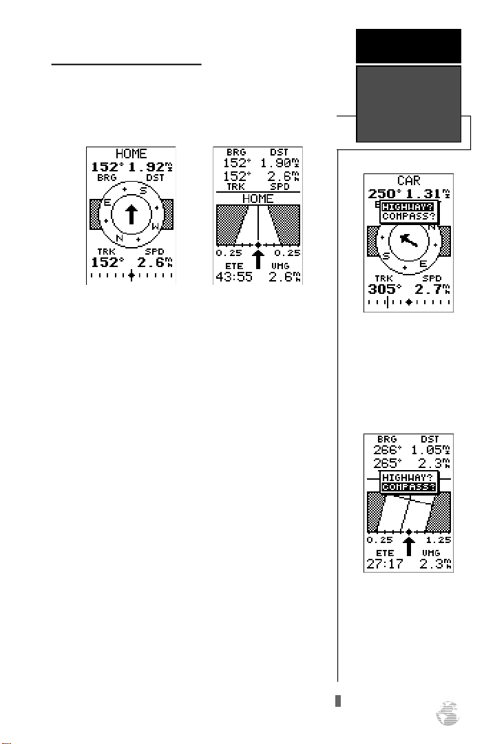
Once you’ve selected a GOTO destination or activate a
MOB or route, the GPS 38 will provide graphic steering
guidance to the destination with one of two navigation
pages:
R E F E R E N C E
Compass and
Highway Pages
Compass Page
Highway Page
•The Compass Page (the default navigation page) provides a directional pointer to the destination, with a
rotating compass graphic to display your direction of
travel. The Compass Page is ideal for activities like
hunting and hiking, and provides better steering guidance for slow-speed (e.g., walking) travel with many
directional changes.
•The Highway Page provides a graphic highway that
shows your movement relative to the desired course,
with an emphasis on your crosstrack error, the distance and direction you are off course. The Highway
Page is well suited for boating and other activities with
higher speeds and straight-line courses to a destination.
Both pages provide a digital display of the bearing and
distance to the destination, along with your current speed
and track over the ground, as well as a course deviation
indicator (CDI). You can select the desired navigation page
at any time.
To select the Compass or Highway Page:
1. Press Puntil the current navigation page appears.
2. Press E. An on-screen box will appear, with the navigation page not currently in use highlighted as the default.
3. Press Eto switch the navigation screen.
To switch the navigation
page to the Highway Page,
press ENTER twice.
To switch the navigation
page to the Compass Page,
press ENTER twice.
37
Page 42
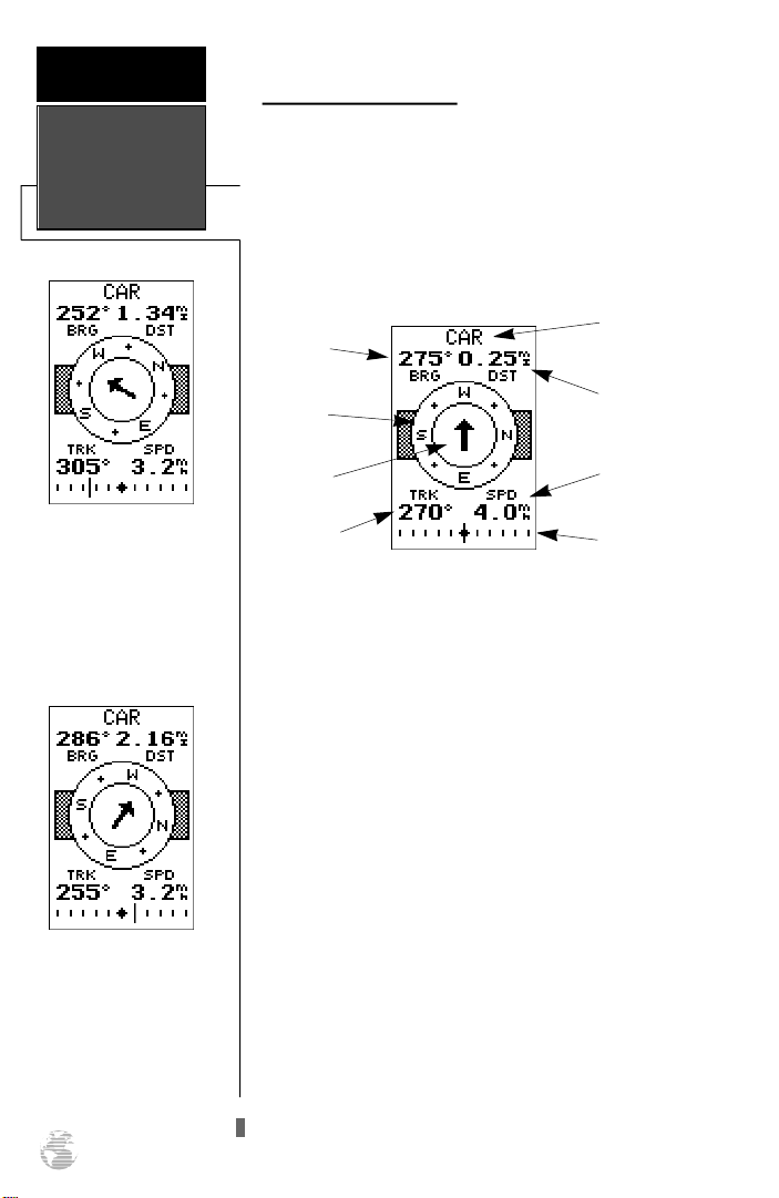
R E F E R E N C E
Compass Page
In this example, the
Compass Page indicates
that you are traveling in a
northwest (305º) direction
and the destination waypoint is southwest (252º) of
your current direction of
travel.
In this example, the
Compass Page indicates
that you are traveling in a
westerly (255º) direction
and the destination waypoint is slightly northwest
(286º) of your current
direction of travel.
38
Using the Compass Page
The GPS 38’s Compass Page provides graphic steering
guidance to a destination waypoint. The bearing (BRG) and
distance (DST) to the waypoint are displayed at the top of
the page, right below the destination waypoint field. The
distance displayed is always the straight line distance from
your present position to the destination waypoint. The
bearing indicates the exact compass heading from you to
the destination.
Bearing to
Waypoint
Graphic
Compass
Pointer to
Waypoint
Track Over
Ground
Destination
Waypoint
Distance to
Waypoint
Speed Over
Ground
CDIScale
The middle of the page features a rotating “compass” that
shows your current heading while you’re moving (desire d
track up), with a pointer arrow in the center. The arrow shows
the direction of your destination from the direction you are
moving. If the arrow points any direction other than up (left,
right, down, etc.), turn toward the arrow until it points up
and then continue in that dire c t i o n .
The bottom of the Compass Page displays your curre n t
track (TRK) and speed (SPD) over the ground, while the CDI
(course deviation indicator) scale shows how far you are off
course. The diamond in the center of the CDI scale re p re s e n t s
your present position, while the d-bar (the moving vert i c a l
line on the scale) indicates the direction and distance you are
o ff the desired straight line course.
To stay on course, steer toward the d-bar until it is cent e red on the position diamond. The default setting of the CDI
scale is +/- 0.25 miles, with each mark re p resenting 0.05 miles
of course deviation. If you do get off course by more than the
selected scale, an arrow prompt will appear at the end of the
scale to indicate the direction you are off course. When you
a re one minute away from the destination (based on your current speed and track over the ground), the GPS 38 will alert
you with a flashing on-screen message box.
Page 43
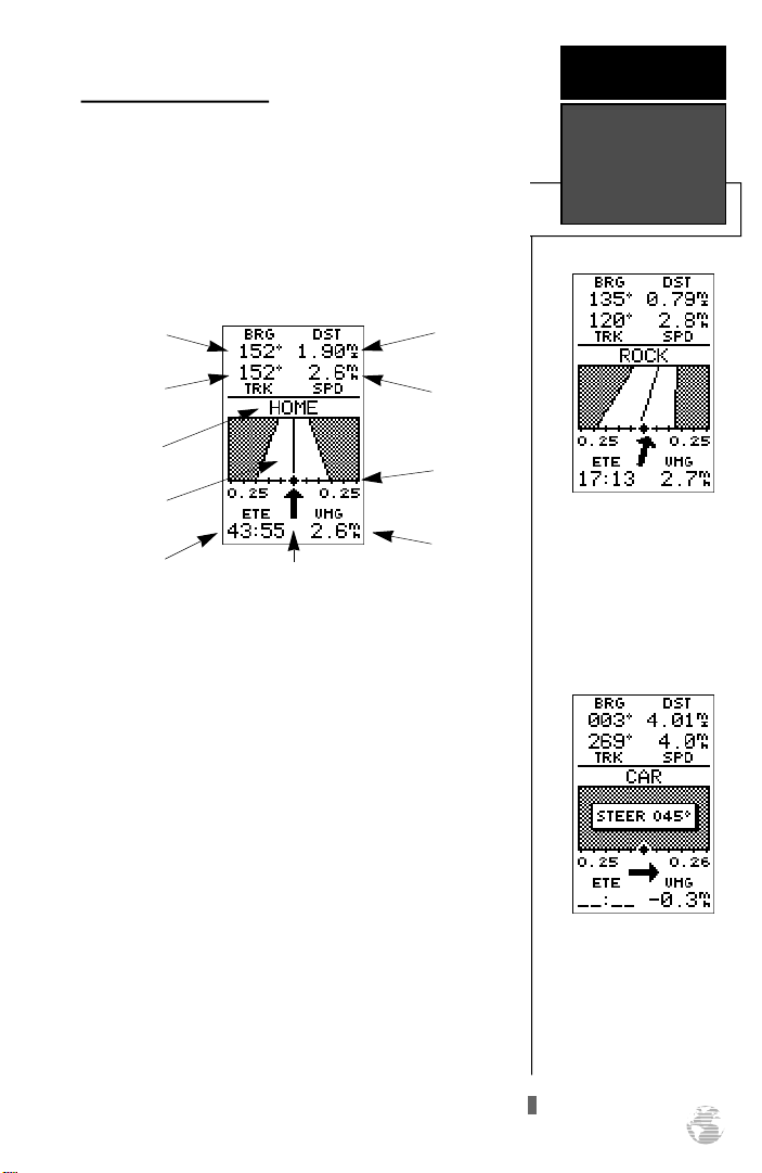
Using the Highway Page
The GPS 38’s Highway Page also provides graphic steering guidance to a destination, with a greater emphasis on
the straight line desired course and the distance and direction you are off course. The bearing and distance to waypoint, along with your current track and speed are displayed at the top of the screen, with your estimated time
enroute (ETE) and velocity made good (VMG, or the rate
you are closing in on your destination) at the bottom.
Bearing to
Waypoint
Distance to
Waypoint
R E F E R E N C E
Highway Page
Track Over
Ground
Destination
Waypoint
Graphic
Highway
Estimated
Time Enroute
Pointer to Waypoint
Speed Over
Ground
CDIScale
Velocity
Made Good
As you head towards your destination, the middle section of the screen provides visual guidance to your waypoint on a moving graphic “highway”. The moving arrow
just below the course deviation scale always points to your
selected waypoint relative to the direction you are moving.
Your present position is represented by the diamond in
the center of the course deviation scale. The line down the
middle of the highway represents your desired track. As
you navigate toward a waypoint, the highway will actually
move, indicating the direction you’re off course, relative to
the position diamond on the CDI scale. To stay on course,
simply steer toward the center of the highway.
If you do get off the desired course by more than 1/5th
of the selected CDI range, the exact distance you are off
course will be displayed where the CDI scale setting normally appears (see the example at right). If you get too far
off course (the highway has disappeared), a message box
will appear to indicate what course to steer to get back on
course most efficiently. As you approach a waypoint, a horizontal “finish line” will move toward the bottom of the
highway. When the finish line reaches the CDI scale, you’ve
arrived at your destination.
In this example, the
Highway Page indicates
that you are off course to the
left. Steer right to get back
on course. Notice the
emphasis of the Highway
Page is on the desire d
course.
If you get too far off course,
a message box will appear
to indicate what course to
steer to get back on course
most efficiently.
39
Page 44
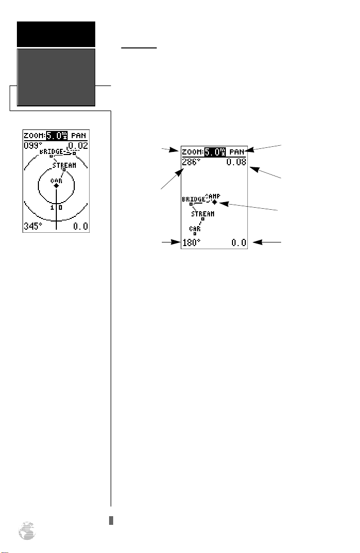
R E F E R E N C E
Map Page
Map Page
The GPS 38 features a powerful real-time moving map
that can do much more than just plot your course and
route. The Map Page also provides you with a target cursor
that will let you pan ahead to nearby waypoints, determine
the distance and bearing to any map position and mark
new waypoints while you navigate.
Range Rings
The GPS 38 has on-screen
range rings to help you estimate distances relative to
your present position. The
value of each ring is deter-
mined by the current zoom
scale, and is equal to 1/5 of
the selected scale.
To turn the range rings display on or off (the default
setting is off), see the map
setup section instructions on
page 49.
40
Zoom Scale
Bearing to
Waypoint
Track Over
Ground
Pan
Field
Distance to
Waypoint
Present
Position
Speed Over
Ground
The Map Page can be broken down into two sections:
The zoom function and panning control fields are located at the top of the screen. There are 12 selectable zoom
ranges from 0.2 to 320 miles or 0.5 to 600 km, measured
vertically.
The map portion of the page displays your present
position as a diamond icon, with your track and/or route
displayed as a solid line. Nearby waypoints are represented
as squares, with the waypoint name also listed. You may
select which of these features are shown through the map
setup submenu page (see page 49 for more information).
The four corners of the Map Page are used to display
various navigation data, including the bearing and distance
to a destination waypoint and your current track and speed
over the ground. The two fields at the top corners of the
map show your bearing and distance to one of three selectable destinations: an active destination waypoint; a highlighted on-screen waypoint; or to the panning target
crosshair. If you are not navigating to a waypoint or using
the panning function, the top data fields will not be displayed. Your current track and speed are shown at the bottom corners of the display.
Page 45
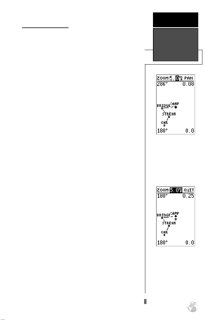
Zooming and Panning
There are three main functions you can perform from
the Map Page— zooming, pointing and panning. Each of
these functions has its own “field”, which may be selected
and activated for use.Whenever the Map Page first appears,
the zoom field (at the top left) is always highlighted. The
moving map has 12 map scales which are selected through
the zoom function field.
To select a zoom scale:
1. Use the arrow keypad to highlight the zoom field.
2. Press the Ekey to begin range selection.
3. Select a range scale.
4. Press Eto confirm your selection.
The second function field on the Map Page is the pan
field, located at the top right of the screen. The pan function allows you to move the map with the four arrow keys
to view areas outside the current map.
To activate the pan function:
1. From the zoom field, highlight the pan field.
2. Press the Ekey to activate the pan function.
R E F E R E N C E
Zooming &
Panning
Selecting Map Scales
To change the map scale,
highlight the zoom field and
press ENTER. Use the Up
and DOWN keys to select
the scale.
3. Use the arrow keys to move the map in any direction.
As you begin to move the map, a crosshair will appear.
This crosshair will now serve as a target marker for the
moving map. The distance and bearing to destination will
now be replaced by the distance and bearing from your
present position to the target crosshair.
As you pan around the map, you’ll notice that the target
crosshair will “snap” to on-screen waypoints and highlight
the waypoint name. Once a waypoint name is highlighted,
you can review its waypoint definition page or execute a
GOTO function right from the Map Page.
To review the definition page for a waypoint high-
lighted in the map field:
1. Press E. To return to the map page, press E.
Panning Function
During panning mode, an
o n - s c reen crosshair will
appear. Your present position will remain as a diamond icon, with the range
and bearing to the crosshair
displayed in the top corners
of the map.
41
Page 46
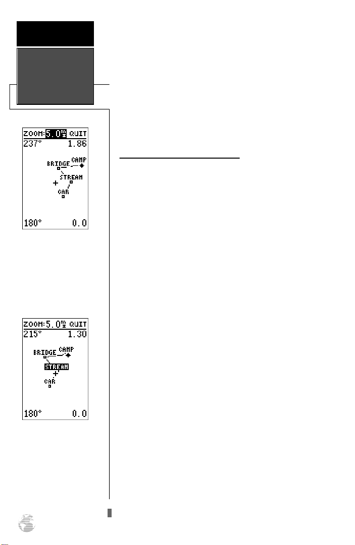
R E F E R E N C E
To go to a waypoint highlighted in the map field:
Using The
Cursor On
The Map
To stop panning, press the
QUIT key.
On-Screen Pointing
The crosshair will “snap” to
waypoints displayed on the
map, which allows you to
quickly review or go to the
selected waypoint right from
the Map Page.
42
1. Press the Gkey.
2. Press the Ekey to confirm the GOTOwaypoint page.
To stop the panning function and display the
present position diamond:
1. Press the Qkey.
Pointing at On-Screen Waypoints
The last field on the Map Page is the map itself. From
the zoom or pan fields, the cursor highlight may be moved
into the map display by pressing the down arrow key. The
arrow keys will now move the field highlight through the
map and “point” at on-screen waypoints.
To point at a displayed waypoint:
1. Use the arrow keys to move the cursor highlight from the
zoom field into the map field.
2. Once you are in the map field, use the four arrow keys to
scroll through on-screen waypoints. The arrow key you
use will determine the direction of your scroll. Once you
have scrolled through all the waypoints, the cursor will
move back to the zoom or pan function field.
Once a waypoint has been selected in the map field, its
distance and bearing from your present position will be displayed at the top corners of the Map Page. You can also
review its waypoint definition page or select it as a GOTO
destination by following the same steps outlined above for
waypoints highlighted on the map field.To get the most out
of panning, you’ll need to be able to zoom in and out while
you’re panning. This lets you move the map at a faster
speed and zoom in for waypoint details. Once the pan
function is activated, the cursor highlight moves back to
the zoom field.
To adjust the zoom range while panning:
1. Press the Ekey to begin range selection.
2. Select the desired range.
3. Press Eto return to normal panning mode.
Page 47
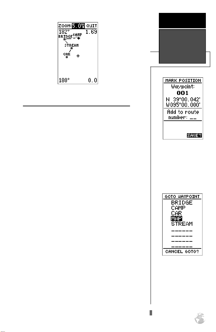
Using the Cursor to Mark and GOTO Waypoints
During panning, the crosshair represents a target position right on the moving map, with the range and bearing
to the target displayed at the top corners of the screen. You
can also use the target crosshair to mark a new waypoint
position or as a GOTO destination right from the map field.
To mark the target crosshair position as a new
waypoint:
1. Press the Mkey to capture the position.
2. Enter a new name and route number if you wish.
3. Press the Ekey to save the waypoint and return to the
map page.
To mark a new waypoint
with the crosshair, simply
pan to the desired position
and press the MARK key.
You can also use the target crosshair as an instant
GOTO destination. Similar to the MOB mode, this function
will mark and instantly set a course for a new waypoint
called ‘MAP’.
To go to the target crosshair:
R E F E R E N C E
Using The
Cursor On
The Map
Marking a Waypoint
1. Press the Gkey to capture the position.
2. Press the Ekey to confirm the MAP GOTO.
If you want to save the MAP waypoint, be sure to
rename it, as it will be overwritten the next time a map
GOTO is executed.
MAPGOTO
The crosshair may also be
used to define a GOTO destination by panning to the
desired position and pressing the GOTOkey. If you
want to save the MAP waypoint, be sure to rename it.
43
Page 48
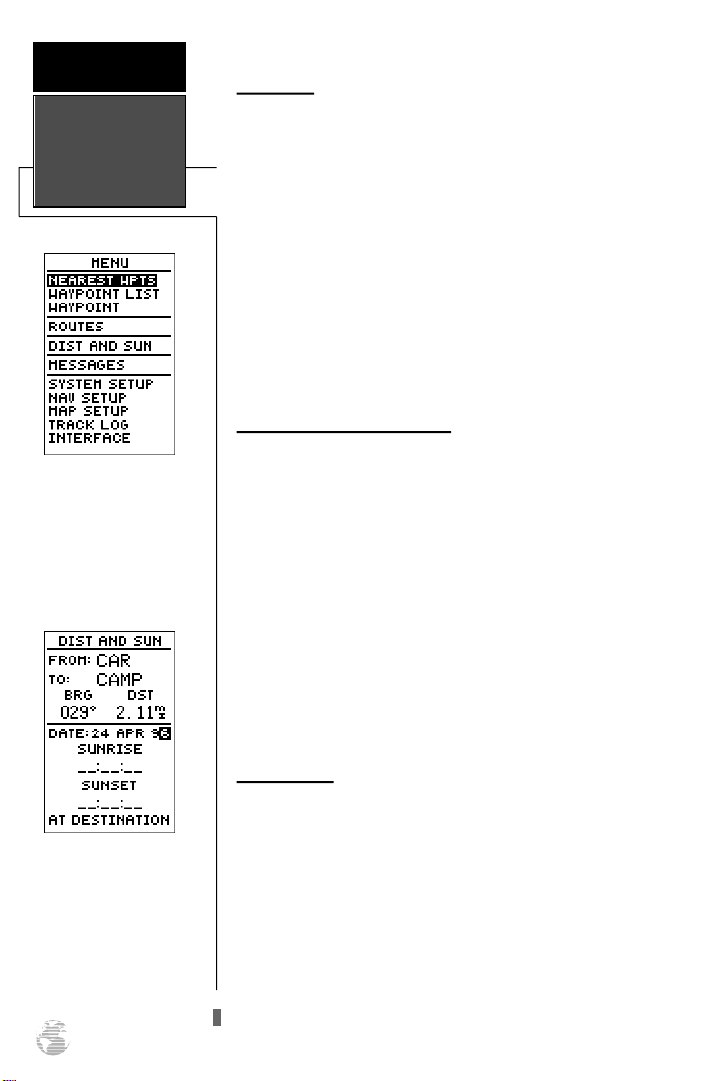
R E F E R E N C E
Menu Page &
Distance/Sun
Calculation
Menu Page
To select a submenu, use the
UP and Down keys to highlight a menu option and
press ENTER.
Menu Page
The GPS 38 Menu Page provides access to submenu
pages that are used to select and customize operation and
navigation setup. The 11 submenus are divided into categories by function. The waypoint and route management
submenus are discussed in their own respective sections.
We’ll now address the rest of the submenus in the order
they appear on the Menu Page.
To select a submenu page from the Menu Page:
1. Highlight the submenu page you want to view.
2. Press the Ekey to display the submenu page.
3. To return to the Menu Page, press the Pkey.
Distance and Sun Calculation
The distance and sun calculation page will give you the
distance and bearing between any two waypoints and calculate the sunrise and sunset (in local time) at a destination
waypoint for a particular date.
To perform a distance and sun calculation:
1. Highlight the ‘FROM’ field and enter the desired waypoint.
Press Eto move to the next field.
2. Highlight the ‘TO’ field and enter the destination waypoint.
Press the Ekey to calculate the range and bearing to
the destination waypoint.
Distance/Sun
Calculation
The GPS 38 will calculate
the sunrise and sunset times
of any stored waypoint or
your present position. To
calculate, enter the date and
year and press ENTER.
44
3. Highlight the ‘DATE’ field and enter the date for your destination. Press the Ekey to display the sun information.
Message Page
The message page displays all current messages in the
GPS 38. There are two types of messages: temporary alerts
(eg. approaching a waypoint) and condition alerts (eg. battery power is low). All messages are initially indicated by a
flashing on-screen box. After a temporary alert has been
viewed, it is cleared. Condition alerts are displayed on the
message page until the condition has been resolved.
To view the message page:
1. Highlight to the ‘MESSAGES’ field and press E.
See appendix A for a complete list of messages.
Page 49
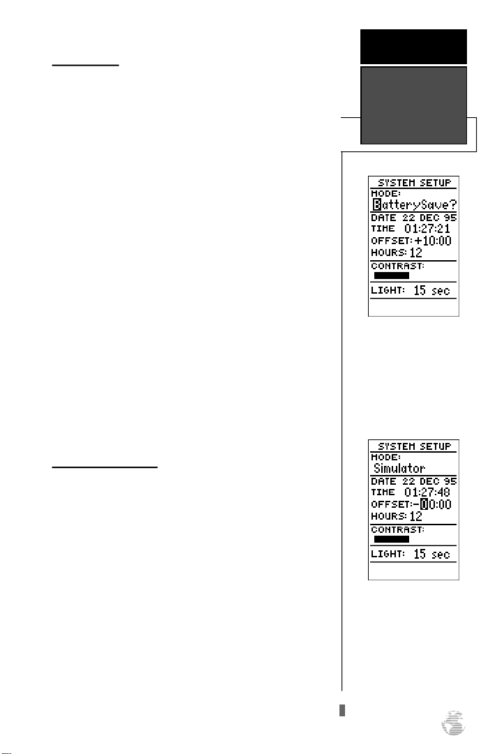
System Setup
The first setup page is the system setup page, which is
used to select the operating mode, time offset and screen
preferences. The GPS 38 has three operating modes:
• Normal Mode operates the unit at maximum performance, and provides a battery life up to 12 hours on
alkaline batteries.
• Battery Saver Mode is suitable for most applications, and extends battery life to up to 20 hours on
alkaline batteries by reducing the receiver’s update
rate when navigational conditions permit (e.g., you’re
traveling a steady course without speed or heading
variations). Since battery saver mode changes the
update rate based solely on navigational conditions,
the battery life will vary accordingly.
• Simulator Mode allows you to operate the unit without acquiring satellites, and is ideal for practicing or
entering waypoints and routes while at home.
To select an operating mode:
1. Highlight the ‘MODE’ field and press E.
2. Use the arrow keypad to select a mode and press E.
R E F E R E N C E
System Setup
System Setup Page
Select battery saver mode to
get the best possible battery
life. Note that screen backlighting will always have the
biggest effect on battery life,
re g a rdless of operating mode.
Date and Time Setup
The date and time field is located directly below the
mode field. Because the time shown is UTC time, you will
need to enter a time offset to display the correct local time
for your area. To determine the time offset for your area,
note your position and refer to the chart in appendix A.
To enter the time offset:
1. Highlight the ‘OFFSET’ field and press the Ekey.
2. Enter the time offset and press E. Remember to select
a positive or negative indicator for your offset.
Time Offset
To display the correct local
time, you must enter the
appropriate offset from the
c h a rt at the end of
Appendix A.
45
Page 50
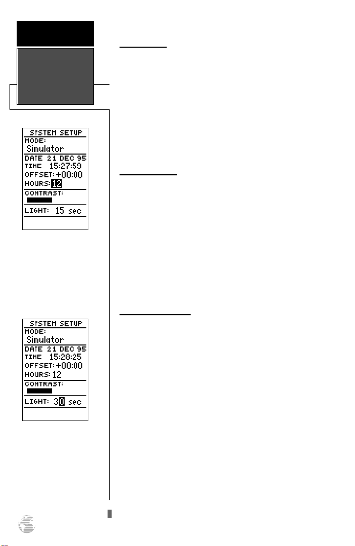
R E F E R E N C E
Setting Time,
Screen Contrast
& Tone
12/24 Hour Clock
To disp lay the time in
AM/PM format, select the
12 hour option from the
‘HOURS’ field.
Time Format
The time display shown on the system setup and
Position Pages may be set to display the time in a 12 or 24
hour format.
To select the time format:
1. Highlight the ‘HOURS’ field and press the Ekey.
2. Use the arrow keypad to select the 12 or 24 hour option.
3. Press Eto confirm.
Screen Contrast
The GPS 38 features adjustable screen contrast for optimum viewing in any condition. The screen contrast is set
by using an on-screen bar scale.
To set the screen contrast:
1. Move the field highlight to the ‘CONTRAST’ field and press
the Ekey.
2. Use the Land Rkeys to adjust the bar scale for the
desired contrast and press the Ekey.
Screen Backlighting
The screen backlight timer is adjustable for
0, 15, 30, 60, 120 and 240 seconds. The ‘0’ setting will
keep the screen backlighting on as long as the unit is on
(NOTE: the default 15 second backlighting setting will provide the longest battery life). Whenever backlighting is on,
a bulb icon will appear on the Satellite Page.
To set the backlight timer:
Screen Backlighting
To get the longest battery
life, keep the screen backlighting at the default 15
second option.
46
1. Highlight the ‘LIGHT’ field and press the Ekey.
2. Select the desired setting. Confirm the setting by pressing
.
E
3. To turn lighting on and off, press Bbriefly.
We’ve now gone through the operation setup submenu
and its various settings. To return to the Menu Page:
1. Press the Pkey.
Page 51
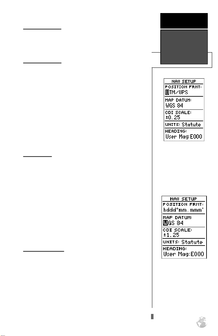
Navigation Setup
The navigation setup page is used to select units of
measurement for position format, map datum, CDI scale,
and distance, speed, and heading information.
Position Formats
The default position setting for the GPS 38 is latitude
and longitude in degrees and minutes (hdddºmm.mmm’).
You may also select degrees, minutes and seconds
(hdddºmm’ss.s’’); degrees only (hddd.dddddº); UTM/UPS
coordinates; or British, German, Irish, Maidenhead,
Swedish, Swiss, or Taiwan grid formats.
To select a position format:
1. Highlight the ‘POSITIONFRMT’ field and press E.
2. Use the Uand Dkeys to select the desired setting.
Confirm the setting by pressing E.
Map Datums
The map datum field is located just below the position
format field, and comes with a WGS 84 default setting.
Although 104 total map datums are available for use (see
the map datum listing in appendix B), you should only
change the datum if you are using maps or charts that specify a different datum than WGS 84.
To select a map datum:
R E F E R E N C E
Navigation
Setup
NAV Setup Page
The position format may be
set to display your position
in various lat/lon or grid
formats.
1. Highlight the ‘MAPDATUM’ field and press E.
2. Select the desired setting. Confirm the setting by pressing
.
E
CDI Scale Settings
The course deviation indicator (CDI) scale definition
field lets you select the +/- range of the CDI bar scale. Three
scales are available: +/- 0.25, 1.25 and 5.0 miles or kilometers, with 0.25 being the default setting.
To enter a CDI scale setting:
1. Highlight the ‘CDISCALE’ field and press E.
2. Select the desired setting.
3. Press the Ekey to confirm the selection.
Map Datum
The GPS 38’s default map
datum is WGS 84.
WARNING: Using the
wrong map datum can seriously affect the accuracy of
your GPS.
47
Page 52
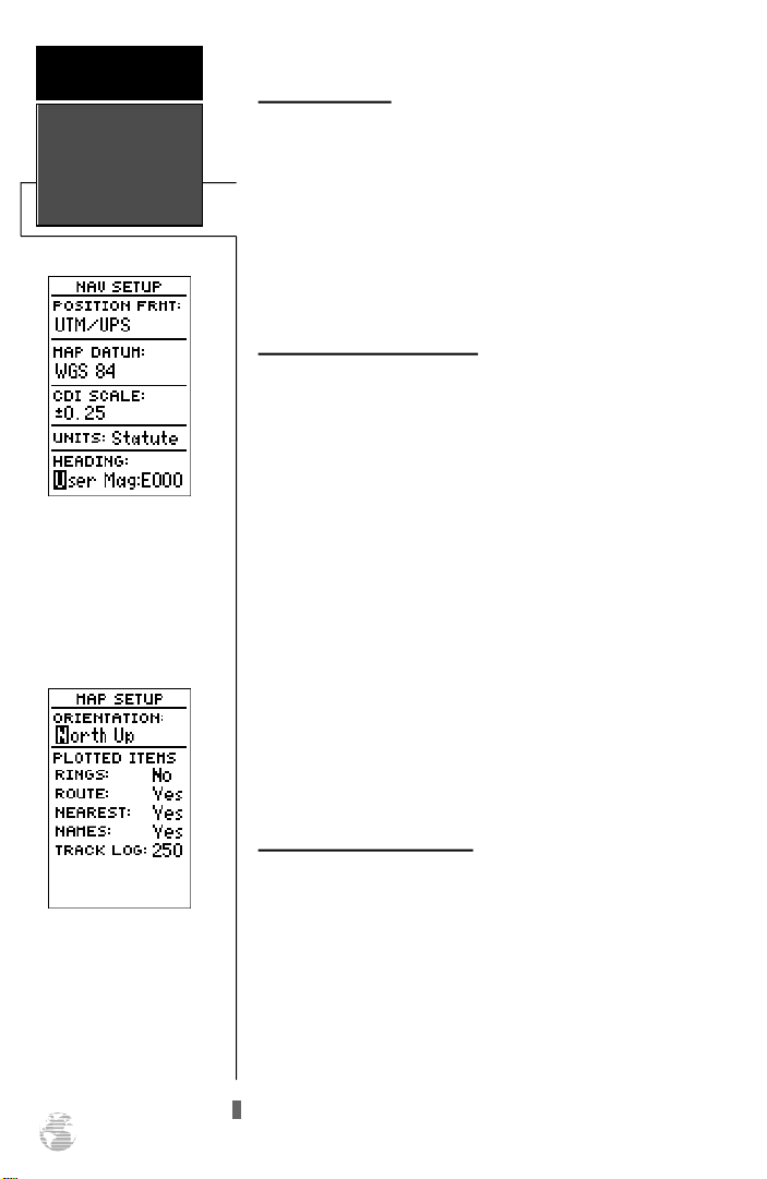
R E F E R E N C E
Navigation
Setup
Units of Measure
The GPS 38 lets you select statute (default), nautical or
metric units of measure for all speed and distance fields.
To change the unit of measure:
1. Highlight the ‘UNITS’ field and press the Ekey.
2. Select the desired unit of measure.
3. Press the Ekey to confirm the selection.
Magnetic Heading Reference
The GPS 38’s heading information can be displayed referencing magnetic north (auto or user-defined), true north
or calculated grid headings. The default setting is automatic
magnetic north, which is suitable for most applications.
To select a heading reference:
Magnetic Heading
To enter a user- d e f i n e d
magnetic variation, select
the ‘User Mag’ option and
enter the desired direction
and value.
Map Setup Page
The map orientation can be
set to track up, north up, or
desired track up. The plot-
ted items options let you
define what appears on the
map display.
48
1. Highlight the ‘HEADING’ field and press E.
2. Select the desired heading preference.
3. Press the Ekey to confirm the selection.
To enter a custom magnetic heading:
. 1. Select the ‘USER MAG’ option and press E.
2. Enter the degrees and direction of magnetic
variation.
3. Press the Ekey to confirm the magnetic
variation value.
Map Setup and Orientation
The map setup page lets you select map orientation and
specify what items are displayed. The map may be oriented
to north up, the direction of current travel (track up) or the
direction of an active route leg (desired track up). The
default setting is track up.
To change the map orientation:
1. Highlight the ‘ORIENTATION’ field and press E.
2. Select the desired setting and press E.
Page 53
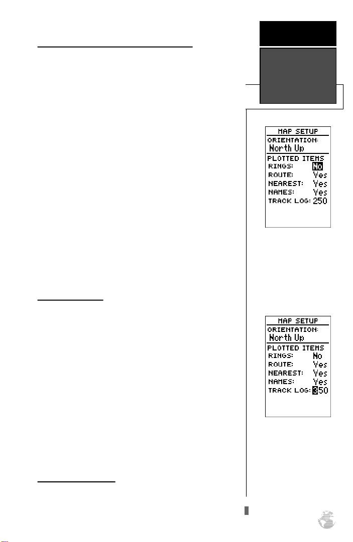
Selecting Displayed Items on the Map Page
The rest of the map setup page lets you specify what
items are displayed or plotted on the Map Page. The first 4
plot items may be turned on or off by selecting ‘Yes’ or ‘No’
in the appropriate field:
• The ‘RINGS’ selection will display the 3 present position range rings on the map.
• The ‘ROUTE’ selection will plot the straight leg lines
between waypoints of an active route and display all
route waypoint names.
• The ‘NEAREST’ selection will display the nine nearest
waypoints to your present position (not to the target
cursor on the map).
• The ‘NAMES’ selection will display the waypoint
name for the nine nearest waypoints.
To turn a plotted item on or off:
1. Highlight the confirmation (Yes or No) field for the plotted
item and press E.
2. Select ‘Yes’ or ‘No’ and press E.
Track Log Display
The track log option sets the number of points the unit
will attempt to display on the Map Page. The default setting
of 250 points provides good resolution with minimal screen
clutter. The maximum setting is 768 points. Once you’ve
reached the maximum number of track points, the older
points will be lost as new points are added. Note that
adjusting the track points displayed will not affect whether
or not the receiver records a track log or the ability to create a TracBack route.
To enter a log setting:
1. Highlight to the ‘TRACK LOG’ field and press E.
2. Enter a value in the 3-digit field and press E. If you do
not want to display a track, enter ‘000’.
Track Log Setup Page
The track log setup page lets you manage the GPS 38’s
tracking data. From this page, you can select whether or
not to record a track and define how it is recorded.
R E F E R E N C E
Map Page &
Track Log Setup
Range Rings
On screen range rings will
appear on the map when
the ‘Rings’ option is set to
the ‘Yes’ position.
Track Log
The track log option only
defines how many points
are displayed on the map.
Setting the value at 000 will
not prevent a track log from
being recorded.
49
Page 54
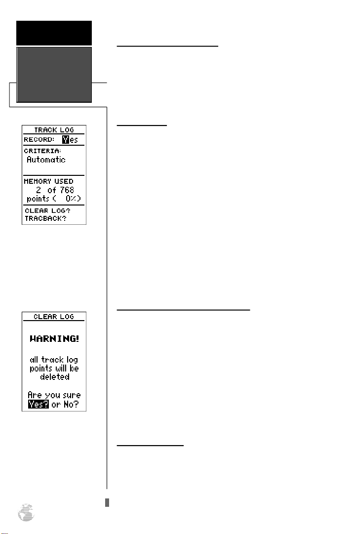
R E F E R E N C E
Navigation Page
Setup
Track Log Page
Turning off the track recording option will prevent you
f rom using the Tr a c B a c k
feature.
Track Log Setup (continued)
To turn the track log on or off:
1. Highlight the ‘RECORD’ field and press E.
2. Select ‘Yes’ or ‘No’ and press E. NOTE: Turning the
track recording off will disable the TracBack feature.
Track Criteria
The stored track criteria determines how often positions
are stored in the track log. The default setting is automatic,
which stores track based on resolution. This setting gives
you the most efficient use of track memory and provides
the most accurate TracBack route.
To change the criteria to record points based upon a
specific time interval:
1. Highlight the ‘CRITERIA’ field and press E.
2. Select ‘Time Interval’ and press E.
3. Press Eto begin entry of the interval.
4. Enter a value in hours, minutes and seconds and press the
key.
E
Managing and Clearing the Track Log
The rest of the track log setup page displays the percentage of available memory currently used to store track
log data and function fields to clear the track log memory
and activate the TracBack feature.
To clear the track log:
To clear the track log, con-
firm the ‘Yes?’ prompt.
50
1. Highlight ‘CLEARLOG?’ and press E.
2. A warning page will appear, asking you to confirm your
actions. Move the field highlight to the ‘Yes?’ field and
press E.
TracBack Function
The TracBack option lets you activate a TracBack route
using the track log (see page 29-30 for more information).
To activate a TracBack route:
1. Highlight the ‘TRACBACK?’ option and press E.
Page 55
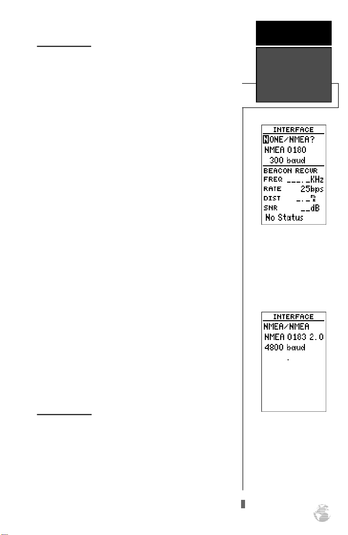
Interface Setup
The GPS 38’s interface setup page lets you specify the
interfacing formats for connecting external devices. There
are five interface options: GRMN/GRMN, None/None,
None/NMEA, RTCM/None, and RTCM/NMEA. Each option
lists the input format first, followed by the output format.
To select I/O format:
1. Highlight the I/O field and press E.
2. Select the desired setting and press E.
The GRMN/GRMN setting is a proprietary format that
lets you exchange information such as waypoints, routes
and track logs between two GARMIN GPS devices or a PC.
During data transfer, the number of packets being
exchanged will be displayed on screen.
To select a transfer option:
1. Highlight the ‘Host’ field and press E.
2. Select a setting and press E.
To disable all interfacing capabilities, select the
None/None setting. If you want to output NMEA data to
compatible external devices without any differential input
capability, select the None/NMEA setting. Once a NMEA
output setting has been selected (with or without RTCM
input), the NMEA field will become highlighted. NMEA
formats 0180, 0182 or 0183 (1.5 or 2.0) are available.
To select a NMEA format:
R E F E R E N C E
Interface Setup
& DGPS Setup
Interface Setup Page
The default interface setting
is the GARMIN/GARMIN
option, which can be used
for unit-to-unit data transfer or interfacing with a
GARMINPCKit.
1. Press Eto begin a NMEA selection.
2. Select a format and press E.
DGPS Interface
The last two format settings allow the differential-ready
GPS 38 to accept RTCM DGPS corrections in RTCM 104
version 2.0 format. Using DGPS corrections will improve
receiver accuracy to 5-10 meters, regardless of errors
induced by the government’s Selective Availability (SA) program. The RTCM/NONE format will allow connection to
any manually tuned beacon receiver with the proper output
interface, with the baud rate selectable from the GPS 38.
NMEAInterface
Once a NMEA format is
selected, the baud rate will
automatically be set to the
proper speed. See Appendix
C for a list of NMEA
sentences.
51
Page 56
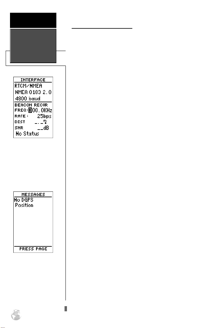
R E F E R E N C E
DGPS Interface
DGPS Interface (continued)
The RTCM/NMEA selection controls the GARMIN GBR21 differential beacon receiver. Once a RTCM setting has
been selected, the GPS 38 will automatically try to tune the
last frequency and bit rate you selected or will switch to the
default frequency of 304.0 kHz with a bit rate of 100 bps if
no previous beacon has been tuned. You may also enter
your own frequency and bit rate if desired.
To enter a DGPS beacon frequency:
1. Highlight the ‘FREQ’ field and press E.
2. Enter the desired frequency and press E.
3. Highlight the ‘RATE’ field and press E.
4. Select the desired transmission rate.
DGPSInterface
Once a RTCM option is
selected, you must manually
tune the beacon re c e i v e r
from the frequency field.
The message page will alert
you to any problems relating to DGPS operation. You
may also monitor the DGPS
status from the status field
on the interface setup page.
52
5. Press the Ekey to confirm your entry.
When the GPS 38 is receiving DGPS corrections from
the GBR-21, the ‘BEACON RECVR’ section of the I/O setup
page will display the beacon frequency and signal strength,
as well as the distance from the transmitter to the beacon
receiver. At the bottom of the beacon receiver field, a status
message will keep you informed of DGPS activity:
• A ‘Tuning’ message will be displayed while a beacon
signal is being tuned.
• Once the beacon signal has been tuned, a ‘Receiving’
message will be displayed.
• If a beacon signal is tuned and no corrections are
being received, a ‘No Data’ message will be displayed.
• If a beacon signal cannot be tuned, a ‘No Status’ mes-
sage will be displayed.
The GPS 38 will also display one of three alert messages
concerning DGPS operation through the message page:
No DGPS Position— not enough data is available to
compute DGPS position.
No RTCM Input— the beacon receiver is not properly
connected or the baud rates do not match.
RTCM Input Failed— DGPS data was being received
but has been lost.
Page 57
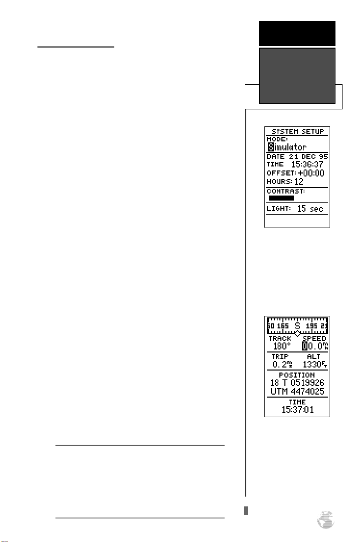
Navigation Simulator
The GPS 38’s simulator mode lets you practice all
aspects of its operation without active satellite acquisition.
You can also plan and practice trips, enter new waypoints
and routes and save them for use during normal operation.
The simulator is activated from the system setup page, with
speed and heading controlled from the Position, Compass,
or Highway pages.
To activate the simulator:
1. Highlight ‘SYSTEMSETUP’ and press E.
2. Highlight the ‘MODE’ field and press E.
3. Select the simulator mode.
4. Press the Ekey to confirm.
R E F E R E N C E
Navigation
Simulator
5. Press Pto return to the Menu Page.
Once the simulator mode has been activated, use the
Position, Compass or Highway Page to set your speed and
track. You may also enter a new position if you desire (only
from the Position Page).
To enter track, speed and position:
1. Highlight the ‘TRACK’ field and press the Ekey.
2. Enter a track heading and press E.
3. Highlight the ‘SPEED’ field and press E.
4. Enter a speed and press E.
5. Highlight the ‘POSITION’ field (Position Page only) and
press E.
6. Enter a position and press the Ekey.
The GPS 38 does not track satellites in simulator
!
#
mode. Although you can create and save waypoints
and routes while using the simulator mode, never
attempt to use the simulator mode for actual navigation. The GPS 38 will always power up in the
Normal mode.
Select the simulator mode
f rom the operation mode
options and press ENTER.
You may return to normal
operation by changing the
operation mode or turning
the unit off.
Speed, Track & Position
Once simulator mode is
selected, speed and track
values may be entered on
the position or navigation
pages. A simulated position
may also be entered on the
Position Page.
53
Page 58

APPENDIX A
The GPS 38 uses a flashing on-screen message indicator
to alert you to important information. Whenever the mes-
Messages &
Time Offsets
sage indicator appears, press Pto view the message page.
There are two types of messages: temporary alerts and condition alerts. Temporary alerts are cleared from the message
page after viewing, while condition alerts remain until the
condition has been resolved. Pay careful attention to all messages for your own safety.
Active WPT Can’t be Deletd—You have attempted to change the “active to”
or “active from” waypoint. Clear the active route or GOTO before making your
changes.
Accuracy has been Degraded—The accuracy of the GPS 38 has been degrad-
ed beyond 500 meters due to poor satellite geometry or data quality. You should
check other navigational sources to verify the position indicated.
Already Exists—The name you are entering already exists in the GPS 38’s
memory.
Approaching—You are one minute away from reaching a destination waypoint.
Battery Power is Low—The batteries are low and should be replaced.
No DGPS Position—Not enough data is available to compute a DGPS posi-
tion.
No RTCM Input—
match.
Poor GPS Coverage—The GPS 38 cannot acquire the necessary number of
satellites to compute a position. Try another location with a clearer view of the
sky.
Power Down and Re-init—The GPS38 is not able to calculate a position due
to abnormal satellite conditions. Turn the unit off and verify the last position
shown by other means. Try the unit again later, possibly in a different location.
Read Only Mem has Failed—The permanent memory has failed and the unit
is not operable. Take your unit to an authorized GARMIN dealer for repairs.
Received an Invalid WPT—A waypoint was received during upload transfer
that has an invalid identifier.
Receiver has Failed—A failure in receiver hardware has been detected. If this
message persists, do not use the unit and take it to an authorized dealer for
repair.
Route is Full—You have attempted to add more than 30 waypoints to a route.
Route is not Empty—You have attempted to copy into a route already in use.
Route Waypoint Can’t be Deleted—The waypoint you are trying to delete is
part of a route. Delete the waypoint from the route before removing it from
memory.
Beacon receiver is improperly connected or baud rates do not
54
Page 59

APPENDIX A
Messages &
Time Offsets
Route Waypoint was Deleted—A route waypoint entered does not exist in
the database and has been deleted from the route.
RTCM Input has Failed—DGPS data being received has been lost. You are no
longer receiving the beacon signal.
Searching the Sky—The GPS 38 is in searching the sky for almanac data or
the unit is in AutoLocateTMmode.
Stored Data was Lost—All waypoints, routes, time and almanac data has
been lost due to battery failure or clearing the receiver’s memory.
Transfer has been Completd—The receiver is finished uploading or downloading information to the connected device.
WPT Memory is Full—You have used all 250 waypoints in the GPS 38. Delete
unwanted waypoints to make room for new entries.
Time Offset Chart
The table below gives approximate UTC time offset for various longitudi-
nal zones. If you are in daylight savings time, add one hour to the offset.
Longitudinal Zone Offset Longitudinal Zone Offset
W180.0º to W172.5º -12 E007.5º to E022.5º 1
W172.5º to W157.5º -11 E022.5º to E037.5º 2
W157.5º to W142.5º -10 E037.5º to E052.5º 3
W142.5º to W127.5º -9 E052.5º to E067.5º 4
W127.5º to W112.5º -8 E067.5º to E082.5º 5
W112.5º to W097.5º -7 E082.5º to E097.5º 6
W097.5º to W082.5º -6 E097.5º to E112.5º 7
W082.5º to W067.5º -5 E112.5º to E127.5º 8
W067.5º to W052.5º -4 E127.5º to E142.5º 9
W052.5º to W037.5º -3 E142.5º to E157.5º 10
W037.5º to W022.5º -2 E157.5º to E172.5º 11
W022.5º to W007.5º -1 E172.5º to E180.0º 12
W007.5º to E007.5º 0
55
Page 60

APPENDIX B
Map Datums
The following list shows the map datums available for
the GPS 38. Menu Page abbreviations are listed first, followed by the corresponding map datum name and area.
The default map datum for the GPS 38 is WGS 84.
56
Adindan Adindan- Ethiopia, Mali,
Senegal, Sudan
Afgooye Afgooye- Somalia
AINELABD ‘70 AIN ELANBD 1970- Bahrain
Island, Saudi Arabia
Anna 1 Ast ‘65 Anna 1 Astro ‘65- Cocos Isl.
ARC 1950 ARC 1950- Botswana,
Lesotho, Malawi, Swaziland,
Zaire, Zambia, Zimbabwe
ARC 1960 ARC 1960- Kenya, Tanzania
Ascnsn Isld ‘58 Ascension Island ‘58-
Ascension Island
Astro B4 Sorol Astro B4 Sorol Atoll- Tern
Island
Astro Bcn “E” Astro Beacon “E”- Iwo Jima
Astro Dos 71/4 Astro Dos 71/4- St. Helena
Astr Stn ‘52 Astronomic Stn ‘52- Marcus
Island
Astrln Geod ‘66 Australian Geod ‘66-
Australia, Tasmania Island
Astrln Geod ‘84 Australian Geod ‘84-
Australia, Tasmania Island
Bellevue (IGN) Efate and Erromango Islands
Bermuda 1957 Bermuda 1957- Bermuda
Islands
Bogata Observ Bogata Obsrvatry- Colombia
Campo Inchspe Campo Inchauspe- Argentina
Canton Ast ‘66 Canton Astro 1966- Phoenix
Islands
Cape Cape- South Africa
Cape Canavrl Cape Canaveral- Florida,
Bahama Islands
Carthage Carthage- Tunisia
CH-1903 CH 1903- Switzerland
Chatham 1971 Chatham 1971- Chatham
Island (New Zealand)
Chua Astro Chua Astro- Paraguay
Corrego Alegr Corrego Alegre- Brazil
Djakarta Djakarta (Batavia)- Sumatra
Island (Indonesia)
Dos 1968 Dos 1968- Gizo Island
(New Georgia Islands)
Easter Isld 67 Easter Island 1967
European 1950 European 1950- Austria,
Belgium, Denmark, Finland,
France, Germany, Gibraltar,
Greece, Italy, Luxembourg,
Netherlands, Norway,
Portugal, Spain, Sweden,
Switzerland
European 1979 European 1979- Austria,
Finland, Netherlands,
Norway, Spain, Sweden,
Switzerland
Finland Hayfrd Finland Hayford- Finland
Gandajika Base Gandajika Base- Republic of
Maldives
Geod Datm ‘49 Geodetic Datum ‘49-
New Zealand
Guam 1963 Guam 1963- Guam Island
Gux 1 Astro Gux 1 Astro- Guadalcanal
Island
Hjorsey 1955 Hjorsey 1955- Iceland
Hong Kong ‘63 Hong Kong ‘63- Hong Kong
Hu-Tzu-Shan Hu-Tzu-Shan- Taiwan
Indian Bngldsh Indian- Bangladesh, India,
Nepal
Indian Thailand Indian- Thailand, Vietnam
Indonesia ‘74 Indonesia 1974- Indonesia
Ireland 1965 Ireland 1965- Ireland
ISTS 073 Astro ISTS 073 ASTRO ‘69-
Diego Garcia
Johnston Island Johnston Island Kandawala
Kandawala- Sri Lanka
Kerguelen Islnd Kerguelen Island
Kertau 1948 Kertau 1948- West Malaysia,
Singapore
L. C. 5 Astro Cayman Brac Island
Liberia 1964 Liberia 1964- Liberia
Luzon Mindanao Luzon- Mindanao Island
Luzon Philippine Luzon- Philippines
(excluding Mindanao Island)
Mahe 1971 Mahe 1971- Mahe Island
Marco Astro Marco Astro- Salvage Island
Page 61

Massawa Massawa- Eritrea (Ethiopia)
Merchich Merchich- Morocco
Midway Ast ‘61 Midway Astro ‘61- Midway
Minna Minna- Nigeria
NAD27 Alaska North American 1927- Alaska
NAD27 Bahamas North American 1927-
Bahamas (excluding San
Salvador Island)
NAD27 Canada North American 1927-
Canada and Newfoundland
NAD27 Canal Zone North Am. 1927- Canal Zone
NAD27 Caribbn North American 1927-
Caribbean (Barbados, Caicos
Islands, Cuba, Dom. Rep.,
Grand Cayman, Jamaica,
Leeward and Turks Islands)
NAD27 Central North American 1927-
Central America (Belize, Costa
Rica, El Salvador, Guatemala,
Honduras, Nicaragua)
NAD27 CONUS North Am. 1927- Mean Value
NAD27 Cuba North American 1927- Cuba
NAD27 Grnland North American 1927-
Greenland (Hayes Peninsula)
NAD27 Mexico N. American 1927- Mexico
NAD27 San Sal North American 1927- San
Salvador Island
NAD83 North American 1983- Alaska,
Canada, Central America,
CONUS, Mexico
Nhrwn Masirah Nahrwn- Masirah Island
(Oman)
Nhrwn Saudi A Nahrwn- Saudi Arabia
Nhrwn United A Nahrwn- United Arab
Emirates
Naparima BWI Naparima BWI- Trinidad and
Tobago
Obsrvtorio ‘66 Observatorio 1966- Corvo
and Flores Islands (Azores)
Old Egyptian Old Egyptian- Egypt
Old Hawaiian Old Hawaiian- Mean Value
Oman Oman- Oman
Ord Srvy GB Old Survey Grt Britn-
England, Isle of Man,
Scotland, Shetland Isl., Wales
Pico De Las Nv Canary Islands
Ptcairn Ast ‘67 Pitcairn Astro ‘67- Pitcairn Isl.
Prov S Am ‘56 Prov So Amricn ‘56- Bolivia,
Chile,Colombia, Ecuador,
Guyana, Peru, Venezuela
APPENDIX B
Map Datums
Prov S Chln ‘63 Prov So Chilean ‘63- S. Chile
Puerto Rico Puerto Rico & Virgin Islands
Qatar National Qatar National- Qatar
Qornoq Qornoq- South Greenland
Reunion Reunion- Mascarene Island
Rome 1940 Rome 1940- Sardinia Island
RT 90 Sweden
Santo (Dos) Santo (Dos)- Espirito Santo
Island
Sao Braz Sao Braz- Sao Miguel, Santa
Maria Islands (Azores)
Sapper Hill ‘43 Sapper Hill 1943- East
Falkland Island
Schwarzeck Schwarzeck- Namibia
Sth Amrcn ‘69 South American ‘69-
Argentina, Bolivia, Brazil,
Chile, Colombia, Ecuador,
Guyana, Paraguay, Peru,
Venezuela, Trinidad and
Tobago
South Asia South Asia- Singapore
SE Base Southeast Base- Porto Santo
and Madiera Islands
SW Base Southwest Base- Faial,
Graciosa, Pico, Sao Jorge and
Terceira Islands (Azores)
Timbalai 1948 Timbalai 1948- Brunei and E.
Malaysia (Sarawak and Sabah)
Tokyo Tokyo- Japan, Korea, Okinawa
Tristan Ast ‘68 Tristan Astro 1968- Tristan da
Cunha
Viti Levu 1916 Viti Levu 1916- Viti Levu/ Fiji
Islands
Wake-Eniwetok Wake-Eniwetok- Marshall Isl.
WGS 72 World Geodetic System 1972
WGS 84 World Geodetic System 1984
Zanderij Zanderij- Surinam
57
Page 62

APPENDIX C
Specifications &
Wiring
PHYSICAL
Case: waterproof*
Size: 6.15”H x 2”W x 1.23”D (15.6 x 5.1 x 1.23 cm)
Weight: Approx 9.5 ounces (269g) w/ batteries
Temperature Range: 5º to 158ºF (-15º to 70ºC)
PERFORMANCE
Receiver: Differential-ready MultiTrac8
Acquisition Time: Approx. 20 seconds (warm start)
Update Rate: 1/second, continuous
Position Accuracy: 5-10 meters (16-33 ft.) with DGPS corrections**
Velocity Accuracy: 0.1 knot RMSsteady state (93 knots/103 mph max.)
Dynamics: Performs to specification to 3g’s
The GPS 38 is constructed of high quality materials and should
not require user maintenance. Should your unit ever need repair,
please take it to an authorized GARMIN service center. The GPS
38 has no user-serviceable parts. Never attempt any repairs yourself. To protect your GPS, keep it covered or in a carrying case
(optional) when not in use, and never allow gasoline or other solvents to come into contact with the case. Clean the case and lens
with a soft cloth and a household window cleaner.
TM
Approx. 2 minutes (cold start)
Approx. 7.5 minutes (AutoLocateTM)
15 meters (49 ft.) RMS***
58
POWER
Input: Four 1.5 volt AA batteries or 5-8 vDC
Power: .75 watts
Battery Life: Up to 12 hours (normal mode)
(w/ alk. batt.) Up to 20 hours (battery saver mode)
NOTE: Alkaline batteries lose a significant amount of their capacity as temperature decreases. If
you’re using the GPS 38 in below freezing temperatures, use lithium batteries for longer
battery life. Extensive use of screen backlighting will significantly reduce battery life.
Specifications subject to change without notice.
* Meets IEC (European Community Specification) 529 IPX7 for protection against immersion for 30 min-
utes at a depth of 1 meter.
** With optional GARMINGBR 21 Beacon Receiver Input.
*** Subject to accuracy degradation to 100m 2DRMS under the US DOD-imposed Selective Availability
Program.
Page 63
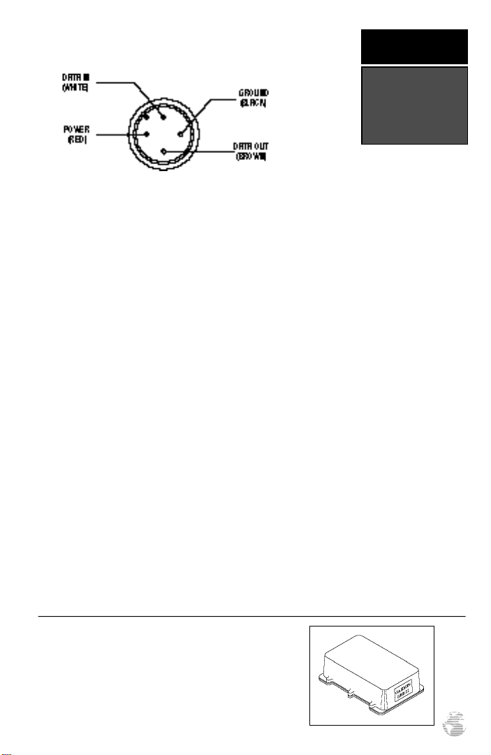
APPENDIX C
(UNIT VIEW)
Specifications &
Wiring
Three optional cables are available to connect the GPS 38 to an external power source or
interface with another unit or PC:
• Cigarette Lighter Adapter (Part No. 010-10084-00) — Allows connection to a 12 volt
DC cigarette lighter plug.
• Data Transfer Cable (Part No. 010-10142-00) — Allows data transfer between
GARMIN GPS units. The GPS 38 is compatible with the following units: GPS
38/40/45/45XL, GPS II/II Plus and GPS12XL units. Information that can be transferred includes the alamanac, waypoints, routes, and tracklog. Some units (ex: GPS II
Plus) contain waypoint symbols. The GPS 38 does not. Waypoint symbols can only be
transferred from and to units supporting waypoint symbols.
• PC Interface Cable (Part No. 010 10141-00) -— PC interface cable with 9-pin ‘D’ serial data connector.
The following interface formats are supported by the GPS 38 for driving three NMEA
devices:
NMEA 0180 NMEA 0182
NMEA 0183 version 1.5
Approved sentences:
GPBWC, GPGLL, GPRMB,
GPRMC,GPXTE, GPVTG,
GPWPL, GPBOD
Proprietary sentences:
PGRMM (map datum),
PGRMZ (altitude), PSLIB
(beacon rec. control)
NMEA 0183 version 2.0
Approved sentences:
GPGGA, GPGLL, GPGSA,
GPGSV, GPRMB, GPRMC,
GPRTE, GPWPL, GPBOD
Proprietary sentences:
PGRME (estimated error),
PGRMM (map datum),
PGRMZ (altitude), PSLIB
(beacon receiver control)
DGPS corrections are accepted on RTCM-104 v. 2.0
format. The GARMINGBR 21 is the recommended beacon receiver for use with the GPS 38. Other receivers
with the correct RTCM format may be used, but may not
correctly display status or allow tuning control from the
GPS 38.
59
Page 64

APPENDIX D
Index
2D Navigation . . . . . . . . . . . . . . .18
3D Navigation . . . . . . . . . . . . . . .18
A
Acquiring Satellites . . . . . . . . . . . . .6
Activating and Inverting Routes . . .34
Active Route Page . . . . . . . . . . . . .35
Almanac Data (defined) . . . . . . . . . .2
Altitude Display . . . . . . . . . . . . . .20
AutoLocate (defined) . . . . . . . . . . . .2
B
Backlight . . . . . . . . . . . . . . . . .19,46
Battery Installation . . . . . . . . . . . . .4
Battery Level Indicator . . . . . . . . .19
Battery Saver Mode . . . . . . . . . . . .45
Bearing (defined) . . . . . . . . . . . . . .2
D
DGPS Interface . . . . . . . . . . . . . . .51
Date and Time Setup . . . . . . . . . . .45
Deleting Routes . . . . . . . . . . . . . . .33
Differential GPS (DGPS) (defined) . .2
Displaying Items on the Map Page .49
Distance and Sun Calculation . . . .44
DTK (defined) . . . . . . . . . . . . . . . .2
E
EZinit . . . . . . . . . . . . . . . . . . . . . . .7
Editing Existing Waypoints . . . . . .26
Editing Routes . . . . . . . . . . . . . . .35
ETA (defined) . . . . . . . . . . . . . . . .2
ETE (defined) . . . . . . . . . . . . . . . .2
G
Getting Started Tour . . . . . . . . . . . .9
Glossary . . . . . . . . . . . . . . . . . . . . .2
Going To A Waypoint . . . . . . . . . .28
Grid (defined) . . . . . . . . . . . . . . . . .2
Ground Speed (defined) . . . . . . . . .2
H
Highway Page . . . . . . . . . . . . . . . .37
C
Cancelling A GOTO . . . . . . . . . . .28
CDI scale . . . . . . . . . . . . . . . . . . .14
CDIScale Settings . . . . . . . . . . . . .47
Caution Statement . . . . . . . . . . . . .ii
Clearing a Cluttered Map Display .16
CMG (defined) . . . . . . . . . . . . . . . .2
Compass Page . . . . . . . . . . . . . . . .13
Copying and Clearing Routes . . . .33
Creating A Route . . . . . . . . . . . . . .32
60
I
Index . . . . . . . . . . . . . . . . . . . . . .60
Initialization . . . . . . . . . . . . . . . . . .5
Initialization Troubleshooting . . . . .8
Interface Setup . . . . . . . . . . . . . . .51
K
Keypad Usage & Data Entry . . . . . .3
L
Latitude (defined) . . . . . . . . . . . . . .2
Longitude (defined) . . . . . . . . . . . .2
M
Magnetic Heading Reference . . . . .48
Man Overboard Function . . . . . . .28
Managing/Clearing the Track Log . .50
Page 65

Map Datums . . . . . . . . . . . . . .47, 56
Map Page . . . . . . . . . . . . . . . . . . .12
Map Setup and Orientation . . . . . .48
Mark /GOTO Wypts with Cursor . .43
Marking And Saving Waypoints . . .21
Marking a Position . . . . . . . . . . . .11
Menu Page . . . . . . . . . . . . . . . . . .15
Messages . . . . . . . . . . . . . . . . . . .54
APPENDIX D
Index
N
Navigation (defined) . . . . . . . . . . . .2
Navigation Pages . . . . . . . . . . . . . .37
Navigation Setup . . . . . . . . . . . . .47
Navigation Simulator . . . . . . . . . . .53
Nearest Waypoints Page . . . . . . . .22
Normal Mode . . . . . . . . . . . . . . . .45
O
On-Route GOTOs . . . . . . . . . . . . .36
Optional cables . . . . . . . . . . . . . . .59
P
Packing List . . . . . . . . . . . . . . . . . . .i
Pointing at On-Screen Waypoints .42
Position Formats . . . . . . . . . . . . . .47
Position Page . . . . . . . . . . . . . . . .10
Power/Data Cable . . . . . . . . . . . . .59
Power On . . . . . . . . . . . . . . . . . . . .9
Power Off . . . . . . . . . . . . . . . . . . .16
Primary Pages . . . . . . . . . . . . . . . .15
R
Range Rings . . . . . . . . . . . . . . . . .40
Reference Waypoints . . . . . . . . . . .25
Removing Waypoints from Routes 36
Renaming & Deleting Waypoints . .26
Routes
Active Route Page . . . . . . . . . . .35
Activating and Inverting . . . . . . .34
Clearing . . . . . . . . . . . . . . . . . .33
Copying . . . . . . . . . . . . . . . . . .33
Creating . . . . . . . . . . . . . . . . . .32
Editing . . . . . . . . . . . . . . . . . . .35
Routes (continutd)
On-Route GOTOs . . . . . . . . . . .36
Removing Waypoints From . . . .36
Route Navigation . . . . . . . . . . . .31
S
Satellite Page . . . . . . . . . . . . . . . . . .6
Scanning Waypoints . . . . . . . . . . .27
Screen Backlighting . . . . . . . . .19, 46
Screen Contrast . . . . . . . . . . . . . . .46
Skyview Display . . . . . . . . . . . . . .16
Specifications & Wiring . . . . . . . .58
Starting/Stopping a GOTO . . . . . .28
T
Table of Contents . . . . . . . . . . . . . .1
Time Format . . . . . . . . . . . . . . . . .46
Time Offsets . . . . . . . . . . . . . . . . .54
TracBack Navigation . . . . . . . . . . .29
Track Criteria . . . . . . . . . . . . . . . .50
Track Log Display . . . . . . . . . . . . .49
Track Log Setup . . . . . . . . . . . . . .49
Trip Odometer . . . . . . . . . . . . . . .20
TRK (defined) . . . . . . . . . . . . . . . . .2
Types of Messages . . . . . . . . . . . . .54
U
Units of Measure . . . . . . . . . . . . . .48
UTM (defined) . . . . . . . . . . . . . . . . 2
V
VMG (defined) . . . . . . . . . . . . . . . .2
61
Page 66

APPENDIX D
Index
W
Warranty . . . . . . . . . . . . . . . . . . .63
Waypoints
Waypoint (defined) . . . . . . . . . . .2
Waypoint Comments . . . . . . . . .26
Waypoint Definition Page . . . . . .24
Waypoint List Page . . . . . . . . . .23
Waypoint Submenus . . . . . . . . .22
Editing . . . . . . . . . . . . . . . . . . .26
Going To A Waypoint . . . . . . . .28
Mark and GOTO with Cursor . .43
Marking And Saving . . . . . . . . .21
Nearest Waypoints Page . . . . . . .22
Pointing at On-Screen . . . . . . . .42
Reference Waypoints . . . . . . . . .25
Removing from a Route . . . . . . .36
Renaming & Deleting . . . . . . . .26
Scanning . . . . . . . . . . . . . . . . . .27
Wrist Strap Attachment . . . . . . . . . .4
X
XTE (defined) . . . . . . . . . . . . . . . . .2
Z
Zooming and Panning . . . . . . . . . .41
62
Page 67

WARRANTY
GARMIN warrants this product to be free from defects in materials
and workmanship for one year from the date of purchase. GARMIN will
at its sole option, repair or replace any components which fail in normal
use. Such repairs or replacement will be made at no charge to the cus-
tomer for parts or labor. The customer is, however, responsible for any
transportation costs. This warranty does not cover failures due to abuse,
misuse, accident, or unauthorized alteration or repairs. GARMIN
assumes no responsibility for special, incidental, punitive, or consequen-
tial damages, or loss of use.
The warranties and remedies contained herein are exclusive, and in
lieu of all other warranties expressed or implied, including any liability
arising under warranty of merchantability or fitness for a particular pur-
pose, statutory or otherwise. This warranty gives you specific legal rights,
which may vary from state to state.
To obtain warranty service, call the GARMIN Customer Service
department (913-397-8200) for a returned merchandise tracking number. The unit should be securely packaged with the tracking number
clearly marked on the outside of the package, and sent freight prepaid
and insured to a GARMIN warranty service station. A copy of the original
sales receipt is required as the proof of purchase for warranty repairs.
GARMIN retains the exclusive right to repair or replace the unit or software at its sole discretion.
63
Page 68

®
© 1997 GARMIN Corporation
1200 E. 151st Street, Olathe, KS USA 66062
GARMIN (Europe) Ltd. Unit 5, The Quadrangle
Abbey Park, Romsey, UK SO51 9AQ
Part Number 190-00112-00 Rev. B Printed in Taiwan
 Loading...