

Page 1
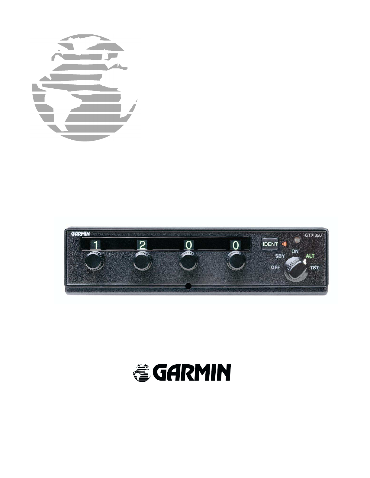
GTX 320/320A
TRANSPONDER
INSTALLATION
MANUAL
(GTX 320 Shown)
GARMIN International, Inc.
1200 E. 151
Olathe, KS 66062 USA
190-00133-01 Revision L
st
June 2001
Street
££££
Page 2
© Copyright 1999-2002
GARMIN Ltd. or its subsidiaries
All Rights Reserved
Except as expressly provided herein, no part of this manual may be reproduced, copied, transmitted,
disseminated, downloaded or stored in any storage medium, for any purpose without the express prior
written consent of GARMIN. GARMIN hereby grants permission to download a single copy of this
manual and of any revision to this manual onto a hard drive or other electronic storage medium to be
viewed and to print one copy of this manual or of any revision hereto, provided that such electronic or
printed copy of this manual or revision must contain the complete text of this copyright notice and provided
further that any unauthorized commercial distribution of this manual or any revision hereto is strictly
prohibited.
Information in this document is subject to change without notice. GARMIN reserves the right to change or
improve its products and to make changes in the content without obligation to notify any person or
organization of such changes or improvements.
GARMIN International, Inc.
1200 E. 151
Olathe, KS 66062 USA
Telephone: 913-397-8200
Dealer Line: 1-800-800-1420
Web Site Address: www.garmin.com
st
Street
INFORMATION SUBJECT TO EXPORT CONTROL LAWS
This document may contain information which is subject to the Export Administration Regulations
(“EAR”) issued by the United States Department of Commerce (15 CFR, Chapter VII, Subchapter C) and
which may not be exported, released, or disclosed to foreign nationals inside or outside of the United States
without first obtaining an export license. A violation of the EAR may be subject to a penalty of up to 10
years imprisonment and a fine of up to US$1,000,000 under Section 2410 of the Export Administration Act
of 1979. Include this notice with any reproduced portion of this document.
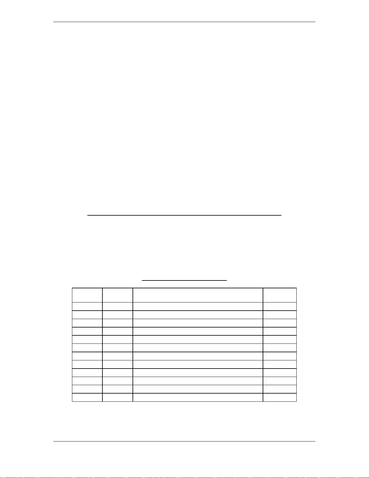
RECORD OF REVISIONS
Revision Revision
Date
A
B
C
D
E
F
G
H
J
K
L
02/10/97 Initial Rel --05/30/97 Clarify Antenna Requirements 7096
07/08/97 Lengthens Mount Screws, Add Notes 7344
08/21/97 Depth Behind Panel 7539
09/18/97 Wiring Diagram Corrections 7673
01/23/98 Add Spring Washer 8310
06/05/98 Correct reference to 50 ohm match bushing 8808
05/14/99 Updates and Corrections 10985
09/25/00 Redraw 14199
11/05/01 Updates and Clarifications 16878
06/06/02 Updated unit and accessory part numbers 18314
Description ECO #
Page A GTX 320/320A Installation Manual
Rev. L 190-00133-01
Page 3

TABLE OF CONTENTS
PARAGRAPH PAGE
1 GENERAL DESCRIPTION .................................................................................................................1
1.1 INTRODUCTION.................................................................................................................................1
1.2 EQUIPMENT DESCRIPTION.............................................................................................................1
1.3 TECHNICAL SPECIFICATIONS........................................................................................................1
1.3.1 Transponder Specifications .......................................................................................................1
1.3.2 Physical Characteristics-GTX 320 ............................................................................................2
1.3.3 Physical Characteristics-GTX 320A..........................................................................................2
1.4 EQUIPMENT AVAILABLE................................................................................................................2
1.4.1 Configurations Available...........................................................................................................2
1.4.2 Installation Accessories .............................................................................................................3
1.5 ADDITIONAL EQUIPMENT REQUIRED.........................................................................................3
1.6 INSTALLATION APPROVAL............................................................................................................3
1.7 ATC TRANSPONDER TESTS AND INSPECTIONS ........................................................................4
1.8 LIMITED WARRANTY ......................................................................................................................4
2. INSTALLATION ..................................................................................................................................5
2.1 INTRODUCTION.................................................................................................................................5
2.2 UNPACKING AND INSPECTING EQUIPMENT..............................................................................5
2.3 ANTENNA INSTALLATION..............................................................................................................5
2.3.1 Location Considerations ............................................................................................................5
2.3.2 Antenna Installation...................................................................................................................5
2.3.3 Installation Approval Considerations for Pressurized Aircraft .................................................6
2.3.4 Antenna Cable Installation ........................................................................................................7
2.3.5 Antenna Cable Connectors ........................................................................................................7
2.4 GTX 320/320A INSTALLATION........................................................................................................9
2.5 ELECTRICAL CONNECTIONS .......................................................................................................10
2.6 CHECK EXISTING COAX AND ANTENNA..................................................................................12
2.7 INSTALLATION USING EXISTING NARCO AT 150 INSTALLATION RACK .........................12
2.8 INSTALLATION USING EXISTING BENDIX/KING 76A/78A INSTALLATION RACK...........13
3. POST INSTALLATION CONFIGURATION & CHECKOUT PROCEDURE................................14
3.1 AIRCRAFT STATION LICENSING REQUIREMENTS .................................................................14
3.2 OPERATION ......................................................................................................................................14
3.2.1 Function Selection Switches....................................................................................................15
3.2.2 Code Selection .........................................................................................................................15
3.2.3 IDENT Button..........................................................................................................................16
3.2.4 Reply Light ..............................................................................................................................16
GTX 320/320A Installation Manual Page i
190-00133-01 Rev L
Page 4

PARAGRAPH PAGE
APPENDIX A. CERTIFICATION DOCUMENTS....................................................................................17
A.1 CONTINUED AIRWORTHINESS ....................................................................................................17
A.2 ENVIRONMENTAL QUALIFICATION FORM - (GTX 320).........................................................20
A.3 ENVIRONMENTAL QUALIFICATION FORM - (GTX 320A)......................................................22
APPENDIX B. ASSEMBLY AND INSTALLATION DRAWINGS ........................................................24
APPENDIX C. STC PERMISSION-GTX 320 ...........................................................................................39
LIST OF ILLUSTRATIONS
FIGURE PAGE
2-1 DB-25 Pin-Out Definitions .................................................................................................................11
3-1 Transponder Front Panel.....................................................................................................................14
B1 GTX 320/320A Outline Drawing........................................................................................................25
B2 GTX 320/320A Connector/Rack Kit Assembly Drawing ..................................................................27
B3 GTX 320/320A Recommended Panel Cutout Dimensions.................................................................29
B4 GTX 320/320A Interconnect Wiring Diagram ...................................................................................31
B5 Dual Transponder Interconnect Wiring Diagram ...............................................................................33
B6 NARCO AT 150 Installation Adapter Assembly Drawing.................................................................35
B7 KING KT 76A/78A Installation Adapter Assembly Drawing............................................................37
Page ii GTX 320/320A Installation Manual
Rev L 190-00133-01
Page 5
1. GENERAL DESCRIPTION
1.1 INTRODUCTION
This manual provides the installation and operating instructions for the GARMIN GTX 320 and the GTX 320A
Transponders. Information pertaining to the maintenance, alignment, and procurement of replacement parts is
found in the GTX 320 Maintenance Manual, P/N 190-00133-02 and the GTX 320A Maintenance Manual, P/N
190-00133-08. After installation of the GTX 320/ GTX 320A, FAA Form 337 must be completed by an
appropriately certificated agency and ATC transponder tests required by 14 CFR, Part 91.413 must be completed
to return the aircraft to service.
1.2 EQUIPMENT DESCRIPTION
The GARMIN GTX 320/320A Transponder is a radio transmitter and receiver that operates on radar frequencies.
Receiving ground radar interrogations at 1030 MHz, it transmits a coded response of pulses to ground-based
radar on a frequency of 1090 MHz.
As with other Mode A/Mode C transponders, the GTX 320/320A replies with any one of 4,096 codes, which
differ in the position and number of pulses transmitted. By “replying” to ground transmissions, your
GTX 320/320A enables ATC computers to display aircraft identification, altitude and ground speed on ATC
radar screens. The GTX 320/320A is equipped with IDENT capability that activates the Special Position
Identification Pulse (SPI) for approximately 20 seconds (18 seconds for the GTX 320A) identifying your
transponder return from other aircraft on the controller’s scope.
1.3 TECHNICAL SPECIFICATIONS
1.3.1 Transponder Specifications
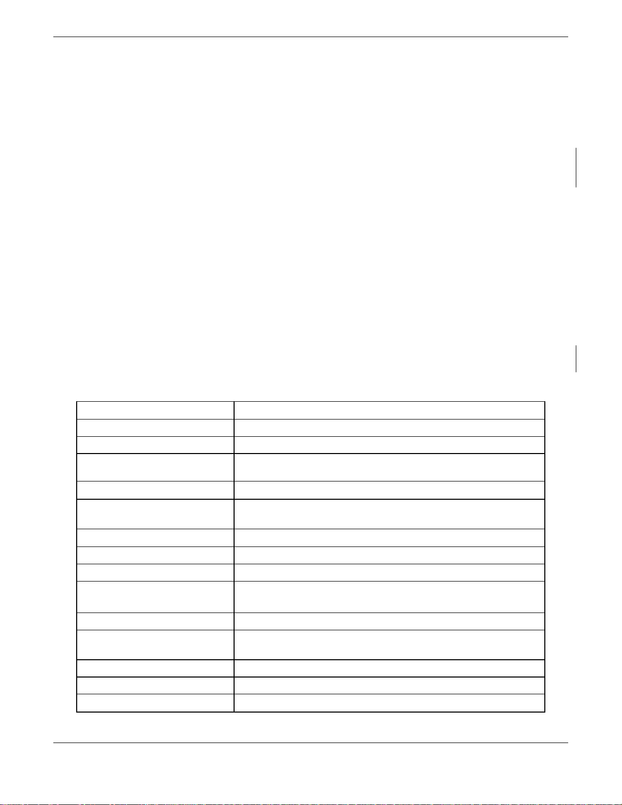
SPECIFICATION CHARACTERISTIC
TSO, JTSO TSO C74c Class 1A, JSTO C74C Class 1A
TSO ENV CAT (A1D1)-CA(BMN)XXXXXXZBABAUZXXXXXX
Applicable Documents
Temperature Range
Power Requirements
Humidity
Altitude 50,000 Feet
Transmitter Frequency 1090 MHz
Transmitter Power
Receiver Frequency 1030 MHz
Receiver Sensitivity
Mode A Capability 4096 Identification Codes
Mode C Capability 100 Foot Increments from -1000 to 63,000 Feet
External Suppression Input
GTX 320: FAA TSO C74c; RTCA DO-160C, JTSO C74c
GTX 320A: FAA TSO C74c; RTCA DO-160D, JTSO C74c
-20°C to +55°C (Continuous Operation)
GTX 320: +11.0 to +33.0 VDC: 12 Watts Max.
GTX 320A: +11.0 to +33.0 VDC: 20 Watts Max.
95% @ +55°C for 16 Hours; 85% @ +38°C for 32 Hours
125 Watts minimum, 150 Watts nominal at the antenna with 1.5
coaxial cable loss at 1090 MHz
GTX 320: -72 dBm Nominal for 90% replies
GTX 320A: -74 dBm Nominal for 90% replies
Low ≤ 0.5 V; High ≥ 8 V
dB
GTX 320/320A Installation Manual Page 1
190-00133-01 Rev L
Page 6
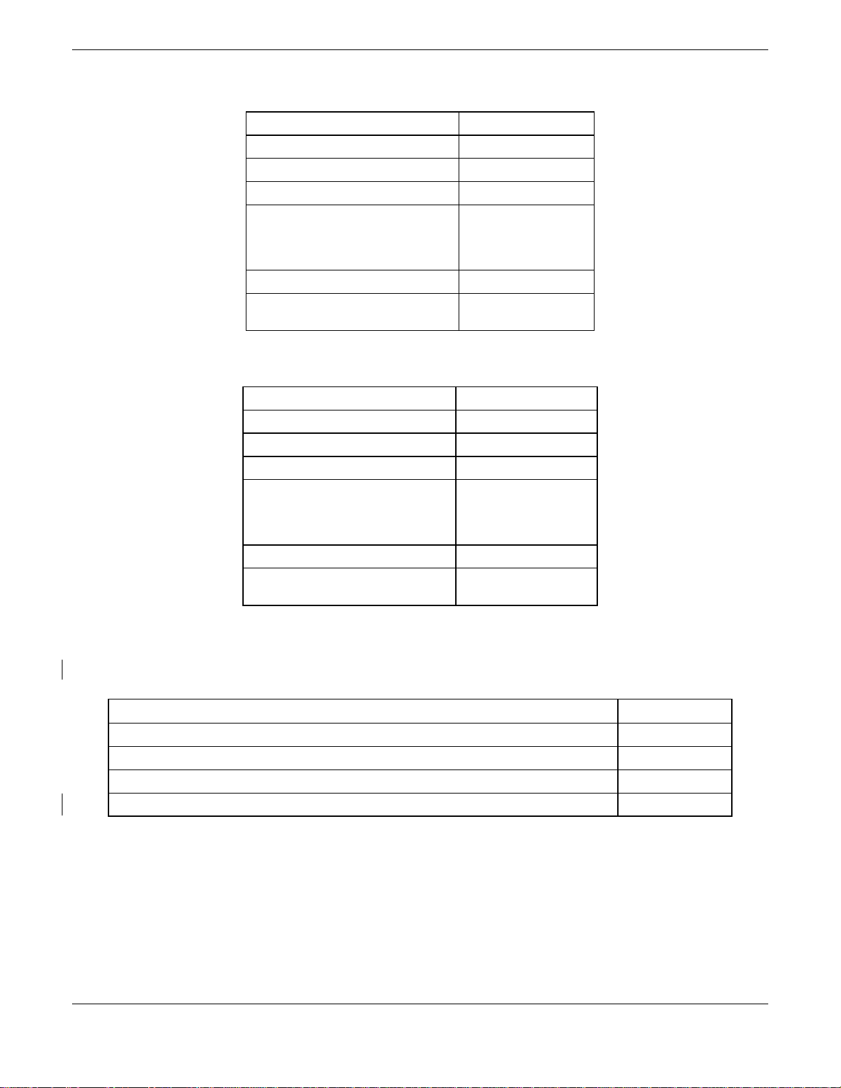
1.3.2 Physical Characteristics-GTX 320
Bezel Height 1.63 inches (41 mm)
Bezel Width 6.25 inches (159 mm)
Rack Height (Dimple to Dimple) 1.71 inches (43 mm)
Rack Width 6.30 inches (160 mm)
Depth Behind Panel with
Connectors (measured from face of
aircraft panel to rear of connector
backshells)
Weight (Unit Only) 1.7 lbs. (0.8 kg)
Weight (Installed with rack and
connectors)
1.3.3 Physical Characteristics-GTX 320A
Bezel Height 1.63 inches (41 mm)
Bezel Width 6.25 inches (159 mm)
Rack Height (Dimple to Dimple) 1.71 inches (43 mm)
Rack Width 6.30 inches (160 mm)
Depth Behind Panel with
Connectors (measured from face of
aircraft panel to rear of connector
backshells)
Weight (Unit Only) 2.3 lbs. (1.1 kg)
Weight (Installed with rack and
connectors)
8.78 inches (223 mm)
2.3 lbs. (1.1 kg)
8.78 inches (223 mm)
2.9 lbs. (1.3 kg)
1.4 EQUIPMENT AVAILABLE
1.4.1 Configurations Available
ITEM GARMIN P/N
GARMIN GTX 320 Transponder 010-00135-00
GARMIN GTX 320A Transponder 010-00247-00
GARMIN GTX 320 Transponder includes GARMIN installation kit, P/N 010-10161-00 010-00135-03
GARMIN GTX 320A Transponder includes GARMIN installation kit, P/N 010-10161-01 010-00247-02
Page 2 GTX 320/320A Installation Manual
Rev L 190-00133-01
Page 7
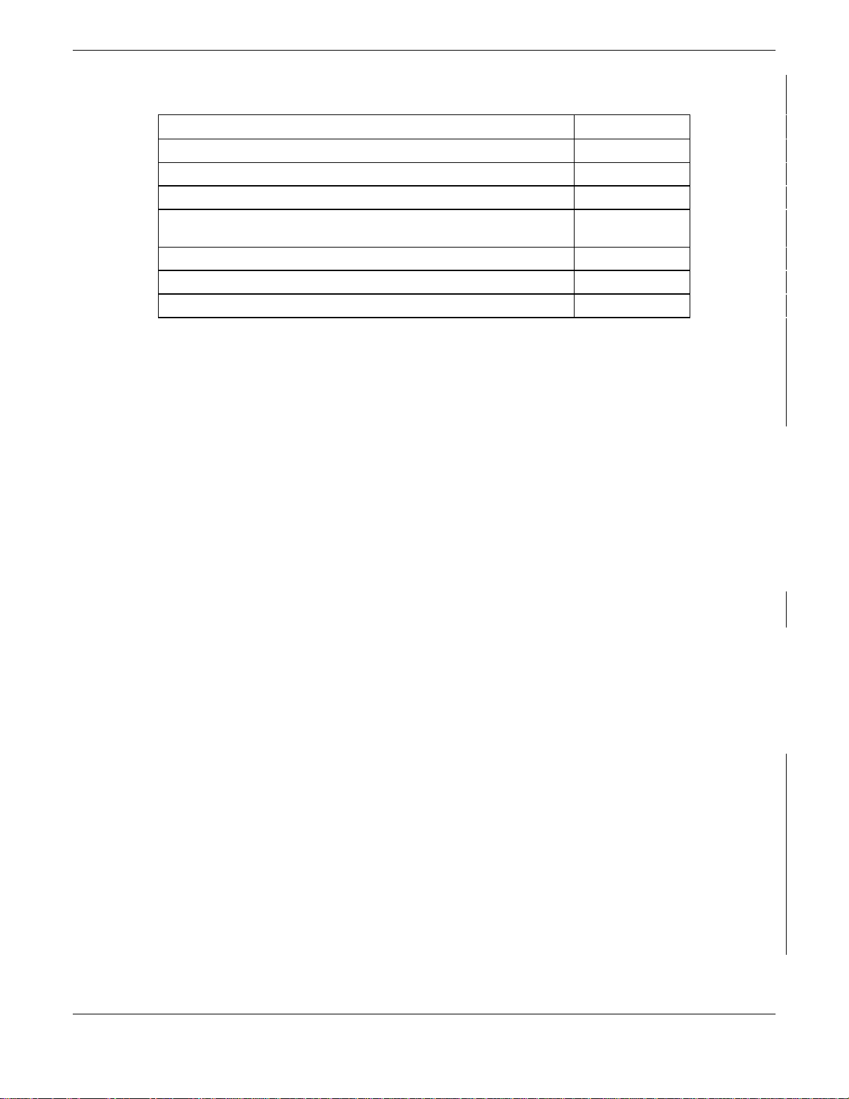
1.4.2 Installation Accessories
ITEM GARMIN P/N
Mounting Rack 115-00285-00
Connector Kit 011-00651-01
Rear Backplate 011-00677-01
Mounting Rack, Rear Backplate and Connector Kit
(Includes 115-00285-00, 011-00677-01 and 011-00651-01)
GARMIN GTX 320/320A Narco Adapter 010-10158-00
GARMIN GTX 320/320A KT76A Adapter 010-10159-00
GARMIN GTX 320/320A Antenna kit* 010-10160-00
010-10161-01
* Note: A transponder antenna approved to TSO C66( ) or C74( ) that has been installed to meet the
requirements of this manual may be approved for use with the GTX 320/320A.
1. 5 ADDITIONAL EQUIPMENT REQUIRED
• Antenna Sealant - Use antenna manufacturer’s instructions, install according to FAA
AC 43.13-2A.
• Cables - The installer will supply all system cables. Cable requirements and fabrication is
detailed in Section 2 of this manual.
• Hardware - #6 Flat Head Screw (6 ea.) and #6-32 Self Locking Nut (6 ea.). Hardware required to
mount installation rack is not provided.
1.6 INSTALLATION APPROVAL
The conditions and tests required for TSO approval of the GTX 320/320A Transponder and antenna are
minimum performance standards. It is the responsibility of those desiring to install this transponder and antenna
either on or within a specific type or class of aircraft to determine that the aircraft installation standards are
within the TSO standards. The GTX 320/320A and antenna may be installed only if further evaluation by the
applicant documents an acceptable installation and is approved by the administrator. For GTX 320/320A TSO
compliance, see Appendix A. For antenna TSO compliance, refer to antenna manufacturer’s literature.
1.7 ATC TRANSPONDER TESTS AND INSPECTIONS
The ATC transponder tests required by 14 CFR, Part 91.413 may be conducted using a bench check or portable
test equipment and must meet the requirements prescribed in Part 43 Appendix F.
If portable test equipment with appropriate coupling to the aircraft antenna system is used, operate the test
equipment for ATCRBS transponders at a nominal rate of 235 interrogations per second to avoid possible
ATCRBS interference. An additional 3 dB loss is allowed to compensate for antenna coupling errors during
receiver sensitivity measurements conducted in accordance with Part 43 Appendix F, Paragraph (c)(1) when
using portable test equipment.
GTX 320/320A Installation Manual Page 3
190-00133-01 Rev L
Page 8

1.8 LIMITED WARRANTY
GARMIN warrants this product to be free from defects in materials and manufacture for one year from the date
of purchase. GARMIN will, at its sole option, repair or replace any components that fail in normal use. Such
repairs or replacement will be made at no charge to the customer for parts or labor. The customer is, however,
responsible for any transportation costs. This warranty does not cover failures due to abuse, misuse, accident or
unauthorized alteration or repairs.
THE WARRANTIES AND REMEDIES CONTAINED HEREIN ARE EXCLUSIVE AND IN LIEU OF ALL
OTHER WARRANTIES EXPRESS OR IMPLIED OR STATUTORY, INCLUDING ANY LIABILITY
ARISING UNDER ANY WARRANTY OF MERCHANTABILITY OR FITNESS FOR A PARTICULAR
PURPOSE, STATUTORY OR OTHERWISE. THIS WARRANTY GIVES YOU SPECIFIC LEGAL RIGHTS,
WHICH MAY VARY FROM STATE TO STATE.
IN NO EVENT SHALL GARMIN BE LIABLE FOR ANY INCIDENTAL, SPECIAL, INDIRECT OR
CONSEQUENTIAL DAMAGES, WHETHER RESULTING FROM THE USE, MISUSE, OR INABILITY TO
USE THIS PRODUCT OR FROM DEFECTS IN THE PRODUCT. SOME STATES DO NOT ALLOW THE
EXCLUSION OF INCIDENTAL OR CONSEQUENTIAL DAMAGES, SO THE ABOVE LIMITATIONS MAY
NOT APPLY TO YOU.
To obtain warranty service, call the GARMIN Customer Service department (913-397-8200) for a returned
merchandise tracking number. The unit should be securely packaged with the tracking number clearly marked on
the outside of the package and sent freight prepaid and insured to a GARMIN warranty service station. A copy
of the original sales receipt is required as the proof of purchase for warranty repairs. GARMIN retains the
exclusive right to repair or replace the unit or software or offer a full refund of the purchase price at its sole
discretion. SUCH REMEDY SHALL BE YOUR SOLE AND EXCLUSIVE REMEDY FOR ANY BREACH OF
WARRANTY.
Page 4 GTX 320/320A Installation Manual
Rev L 190-00133-01
Page 9

2. INSTALLATION
2.1 INTRODUCTION
This section provides the necessary information for installing the GTX 320/320A Transponders, and where
required, optional accessories. Installation of the GTX 320/320A will differ according to equipment location and
other factors. Cabling will be fabricated by the installing agency to fit these various requirements. This section
contains interconnect diagrams, mounting dimensions, and information pertaining to installation. Each
installation shall be accomplished to meet the requirements of FAA AC 43.13-2A.
2.2 UNPACKING AND INSPECTING EQUIPMENT
Carefully unpack the equipment and make a visual inspection of the unit for evidence of damage incurred during
shipment. If the unit is damaged, notify the carrier and file a claim. To justify a claim, save the original shipping
container and all packing materials. Do not return the unit to GARMIN until the carrier has authorized the claim.
Retain the original shipping containers for storage. If the original containers are not available, a separate
cardboard container should be prepared that is large enough to accommodate sufficient packing material to
prevent movement.
2.3 ANTENNA INSTALLATION
2.3.1 Location Considerations
A. The antenna (GARMIN P/N 010-10160-00) should be well removed from any major protrusions, the
engine(s), propeller(s), and antenna masts. It should also be as far removed as practical from
landing gear doors, access doors, or other openings that could alter its radiation pattern.
B. The antenna should be mounted on the underside of the aircraft and in a vertical position when the
aircraft is in level flight.
C. Avoid mounting the antenna within three feet of the ADF sense antenna or any other
communication antenna and six feet from the DME antenna.
D. To prevent RF interference, the antenna must be physically mounted a minimum distance of three
feet from the GTX 320/320A.
If the antenna is being installed on a composite aircraft, ground planes must sometimes be added.
Conductive wire mesh, radials, or thin aluminum sheets embedded in the composite material provide
the proper ground plane allowing the antenna pattern (gain) to be maximized for optimum
transponder performance.
2.3.2 Antenna Installation
Install the antenna according to the antenna manufacturer’s instructions and FAA AC 43.13-2A.
NOTE
GTX 320/320A Installation Manual Page 5
190-00133-01 Rev L
Page 10

2.3.3 Installation Approval Considerations for Pressurized Aircraft
Antenna and cable installations on pressurized cabin aircraft require FAA approved installation design and
engineering substantiation data whenever such installations incorporate alteration (penetration) of the cabin
pressure vessel by connector holes and/or mounting arrangements.
For needed engineering support pertaining to the design and approval of such pressurized aircraft antenna
installations, it is recommended that the installer proceed according to any of the following listed alternatives:
1. Obtain approved antenna installation design data from the aircraft manufacturer.
2. Obtain an FAA approved Supplemental Type Certificate (STC) pertaining to and valid for the subject
antenna installation.
3. Contact the FAA Aircraft Certification Office in the appropriate Region and request identification of FAA
Designated Engineering Representatives (DERs) who are authorized to prepare and approve the required
antenna installation engineering data.
4. Obtain FAA Advisory Circular AC-183C and select (and contact) a DER from the roster of individuals
identified there under.
Contact an aviation industry organization such as the Aircraft Electronics Association and request their
assistance.
Page 6 GTX 320/320A Installation Manual
Rev L 190-00133-01
Page 11
2.3.4 Antenna Cable Installation
When routing antenna cables, observe the following precautions:
• All cable routing should be kept as short as possible and as direct as possible.
• Avoid sharp bends.
• Avoid routing cables near power sources (e.g., 400 Hz generators, trim motors, etc.) or near
power for fluorescent lighting.
• Avoid routing cable near ADF antenna cable (allow at least a 12-inch separation).
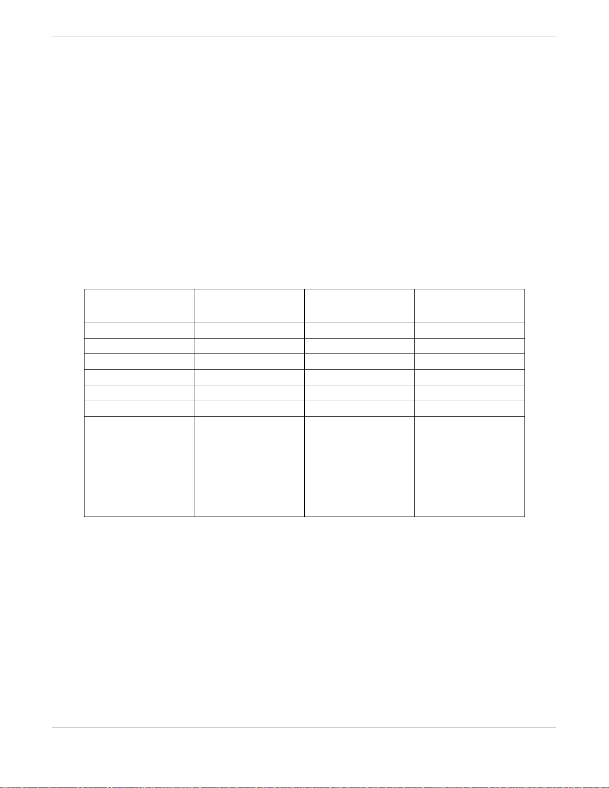
The table below lists the recommended 50 ohm double shielded coax antenna cable vendor and the type to be
used for specific lengths of cable. Adherence to this table will ensure that the coax installation will not exceed
the maximum allowable 1.5 dB attenuation at the transmitter operating frequency of 1090 MHz.
Max. Length (feet) ECS Type MIL-C-17 Type RG Type
8.8 M17/128 RG400
10.0 3C142B
12.5 M17/112 RG304
17.0 311601 M17/127 RG393
21.0 311501
27.0 311201
41.0 310801
Supplier Information
Vendor: Electronic
Cable Specialists
5300 W. Franklin Drive
Franklin, WI 53132
Tel: 800-327-9473
414-421-5300
Fax: 414-421-5301
MIL-C-17 types: See
current issue of
Qualified Products List
QPL-17.
RG types: See current
issue of Qualified
Products List QPL-17.
2.3.5 Antenna Cable Connectors
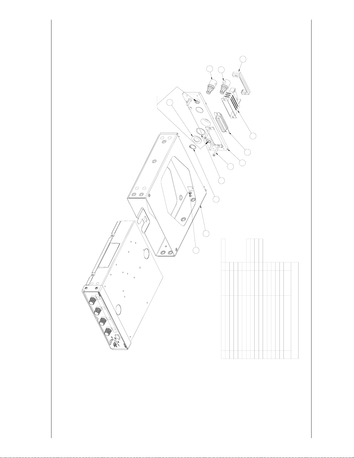
One of two rack connectors is provided (item 6 or 12 in the installation drawing, figure B2). RF Adapter item 12
(P/N 330-00326-00) requires the cable to be terminated to an appropriate type BNC plug (provided by installer),
which is then attached to item 12. Any 50 ohm, double shielded cable may be used, provided it introduces less
than 1.5 dB attenuation at 1 GHz including the connector.
Connector item 6 (P/N 330-00198-00) requires the cable to be terminated directly to it and can accommodate
only M17/128 (RG-400) cable. The completed cable including connectors must introduce no more than 1.5
attenuation at 1 GHz. Instructions for installing the item 6 are shown below (steps A-G).
GTX 320/320A Installation Manual Page 7
190-00133-01 Rev L
dB
Page 12
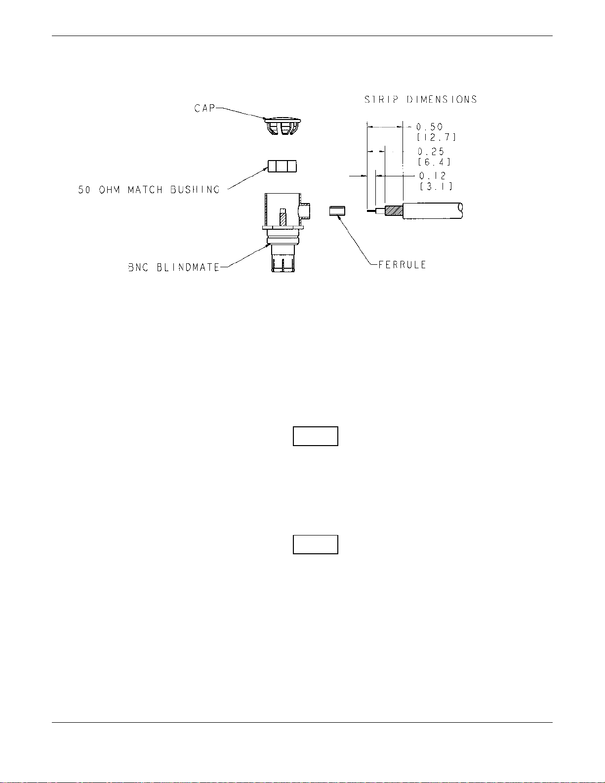
A. Trim coax outer insulation back 0.50".
B. Trim braid (not center conductor or insulation) back 0.25".
C. Strip Insulation back 0.120".
NOTE
Place the ferrule over the coax braid, flush against the coax outer insulation before performing the
next step if the outside diameter of the coax braid is smaller than the inside diameter of the center
connector sidewall opening.
D. Insert cable (center conductor, dielectric and shield braid) through the sidewall of the connector and
solder the center conductor to the center pin of the connector.
NOTE
When using low loss cable it may be necessary to flatten the solid wire center conductor slightly so
it can fit the slot on the RF connector center pin. When soldering, avoid applying excess heat to the
connector body, and center conductor insulator.
E. Heat the outside of the connector sleeve and at the same time apply solder between the braid and the
sleeve. Continue to apply heat until the solder flows evenly.
F. Install 50 1 Matching Bushing.
G. Insert connector cap and tack solder in two places.
Page 8 GTX 320/320A Installation Manual
Rev L 190-00133-01
Page 13

2.4 GTX 320/320A INSTALLATION
Avoid installing the unit near heat sources. If this is not possible, ensure that additional cooling is
provided. Allow adequate space for installation of cables and connectors. The installer will supply
and fabricate all of the cables. All wiring must be in accordance with FAA AC 43.13-2A.
GTX 320 units that are at Mod Level 1 must use the Mod Level 1 Rack Assembly. After Mod
Level 1, GTX 320 installations are 0.170" (4.31 mm) deeper in the panel.
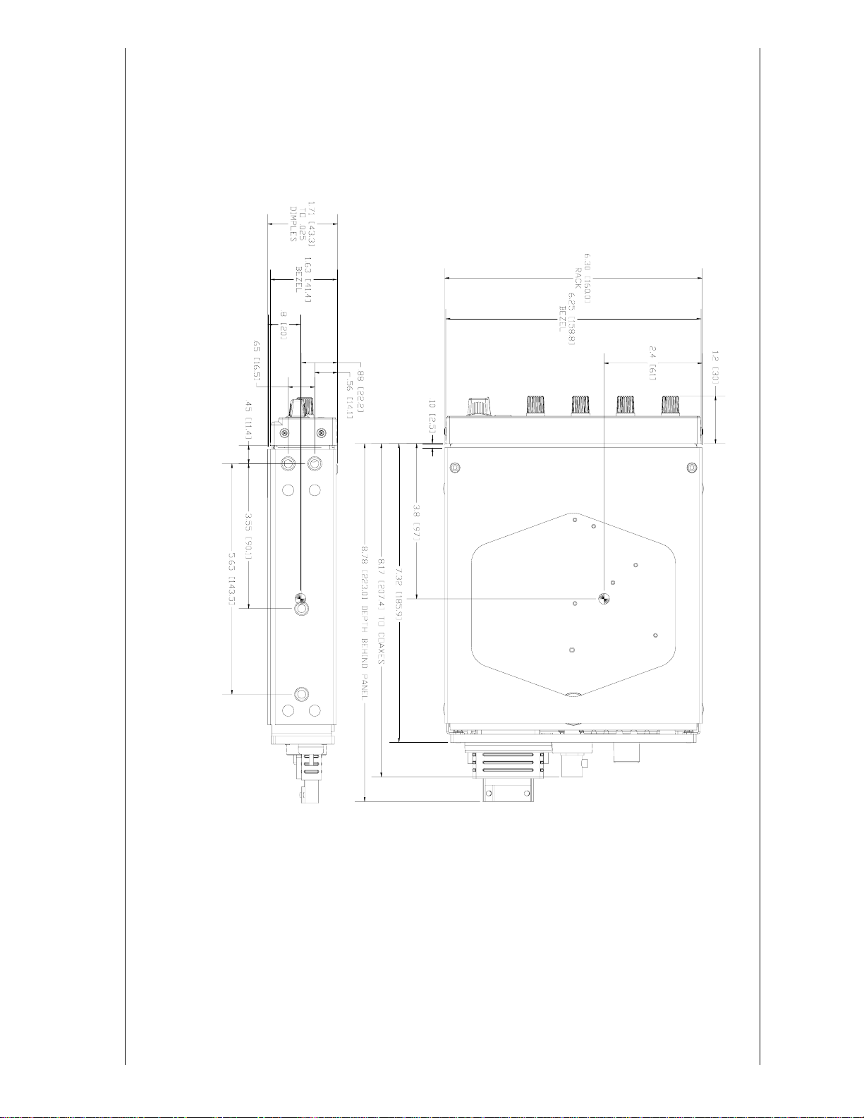
A. Assemble the connector/rack kit according to figure B2. Install the rack assembly according to the
dimensions given in figures B1. Mounting brackets are not supplied due to the wide range of
mounting configurations available. Suitable mounting brackets may be fabricated from sheet metal
or angle stock. To ensure a sturdy mount, rear support for the unit should be provided.
B. Do not insert screws through the rear plate of the mounting tray, into the transponder. These holes
are only for use with the adapter described in paragraph 2.8.
C. Looking at the bottom of the transponder, make sure the front lobe of the locking mechanism is in a
vertical position. This can be accomplished by using a 3/32" Allen wrench through the face plate.
NOTES
D. Slide the unit into the rack until the front lobe of the unit touches the rack. Guide pins on the back
plate will help in the proper alignment of the unit in the rack.
E. Turn the Allen wrench clockwise until unit is secured in the rack. Continue turning until tight. Do
not overtighten the screw.
F. To remove the unit from the rack, turn the 3/32" Allen wrench counterclockwise until it disengages
from the rack.
GTX 320/320A Installation Manual Page 9
190-00133-01 Rev L
Page 14
2.5 ELECTRICAL CONNECTIONS
All electrical connections, except for the antenna, are made through a single, 25 pin, D subminiature connector.
Figure 2-1 defines the electrical characteristics of all input and output signals and identifies the cable
requirements for each signal. Required connector and associated hardware are supplied in the installation kit
(P/N 010-10160-00). See figures B4 and B5 for interconnect wiring diagrams.
Larger pins are supplied for the connector to provide power and ground at pins 13, 14, 15, and 25 when required.
Refer to Figure B4, Note 3.
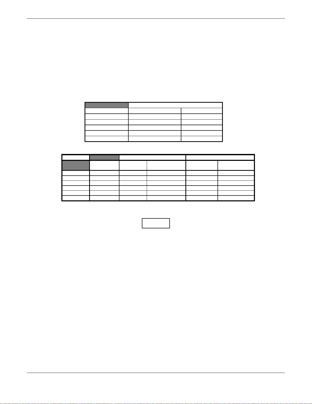
Pin Contact Part Numbers
25 pin connector (P102)
Wire Gauge 18 AWG 20-24 AWG
GARMIN P/N 336-00023-00 336-00022-00
Military P/N N/A M39029/63-368
AMP N/A 205090-1
Positronic FC6018D M39029/63-368
ITT Cannon See Note 3 031-1007-042
Recommended Crimp Tools
Wire Gauge 18 AWG 20-24 AWG
Hand Crimping
Tool
Military P/N M22520/2-01 N/A M81969/1-02 M22520/2-08 M81969/1-02
Positronic 9507 9502-11 M81969/1-02 9502-5 M81969/1-02
ITT Cannon 995-0001-584 N/A N/A 995-0001-604 980-2000-426
AMP 601966-1 N/A N/A 601966-5 91067-2
Daniels AFM8 K774 M24308/1-02 K13-1 M24308/1-02
Astro 615717 N/A M81969/1-02 615724 M81969/1-02
Positioner Insertion/
Extraction Tool
Positioner Insertion/
Extraction Tool
NOTES
1. Insertion/extraction tools from ITT Cannon are all plastic; others are plastic with metal tip.
2. Non-GARMIN part numbers shown are not maintained by GARMIN and consequently are subject to
change without notice.
3. Alternate contacts for 18 AWG wire: As an alternative to the Positronic contacts listed (and provided
in the installation kit), the installer may use contacts made by ITT Cannon under P/N 031-1007-001.
These contacts require the use of a different crimp tool positioner than shown in the table, with the part
numbers as follows: Daniels P/N K250, Astro P/N 616245, or ITT Cannon P/N 980-0005-722.
4. All wires must be passed through the backshell before being assembled to connector.
5. In aircraft equipped with a dropping resistor for +28 VDC buss voltage, make sure the dropping
resistor is bypassed.
Page 10 GTX 320/320A Installation Manual
Rev L 190-00133-01
Page 15
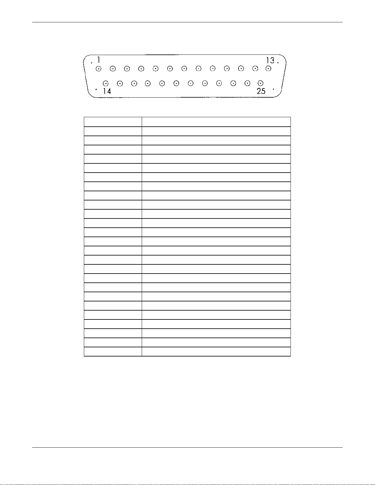
PIN DESCRIPTION
1 Not Used
2 Do Not Connect
3 Altitude A1
4 Altitude C2
5 Altitude A2
6 Altitude A4
7 Altitude C4
8 External Ident
9 Altitude B1
10 Altitude C1
11 Altitude B2
12 Altitude B4
13 Ground
14 Switched Power Output
15 Aircraft Power (+11 to +33 VDC)
16 External Standby
17 External Suppression (Suppress I/O-GTX 320A)
18 Altitude D4
19 Not Used
20 Not Used
21 Not Used
22 Not Used
23 28 V Lighting
24 14 V Lighting
25 Ground
Figure 2-1. DB-25 Pin-Out Definitions
GTX 320/320A Installation Manual Page 11
190-00133-01 Rev L
Page 16

2.6 CHECK EXISTING COAX AND ANTENNA BEFORE USING A GTX 320/320A
ADAPTER IN AN EXISTING INSTALLATION
CAUTION
Before using a Narco or Bendix/King Adapter to install a GTX 320/320A into an existing
installation, the RF coaxial cable, its connectors, and the antenna must be checked to ensure the
following:
• There must be no corrosion or damage on the coax or its RF connectors that would adversely
affect operation.
• The RF attenuation of the coax from the installation rack to the antenna must not exceed 1.5
at 1090 MHz.
• The antenna must not have corrosion, damage, or loose connections.
2.7 INSTALLATION USING EXISTING NARCO AT 150 INSTALLATION RACK
The GTX 320 and GTX 320A can be used with an existing NARCO AT 150 Installation Rack by using the
NARCO AT 150 Installation Adapter (P/N 011-00292-00). See figure B6 for the NARCO AT
assembly drawing.
150 Adapter
NOTES
GTX 320 units that are at Mod Level 1 must use the Mod Level 1 NARCO Installation Adapter.
After Mod Level 1, the GTX 320 sits 0.17" (4.3 mm) closer to the instrument panel. Also, when
installing the GTX 320 in an existing NARCO AT 150 rack (using the AT 150 Adapter) and when
the aircraft has a bus voltage of +28 VDC, make sure the +28 VDC dropping resistor is bypassed.
A. Slide the adapter into the rack installation until the jackscrew mates with its nut.
B. Turn the jack screw with a 3/32" Allen wrench until the adapter is secure.
dB
C. Looking at the bottom of the transponder, make sure the front lobe of the locking mechanism is in a
vertical position. This can be accomplished by using a 3/32" Allen wrench through the face plate.
D. Slide the unit into the rack until the front lobe of the unit touches the rack. Guide pins on the back
plate will help properly align the unit in the rack.
E. Turn the Allen wrench clockwise until unit is secured in the rack. Continue turning until tight. Do
not overtighten the screw.
F. To remove the unit from the rack turn the 3/32" Allen wrench counterclockwise until it disengages
from the rack.
Page 12 GTX 320/320A Installation Manual
Rev L 190-00133-01
Page 17

2.8 INSTALLATION USING EXISTING BENDIX/KING KT 76A/78A INSTALLATION
RACK
The GTX 320 and GTX 320A can be used with an existing Bendix/King KT 76A/78A installation rack by using
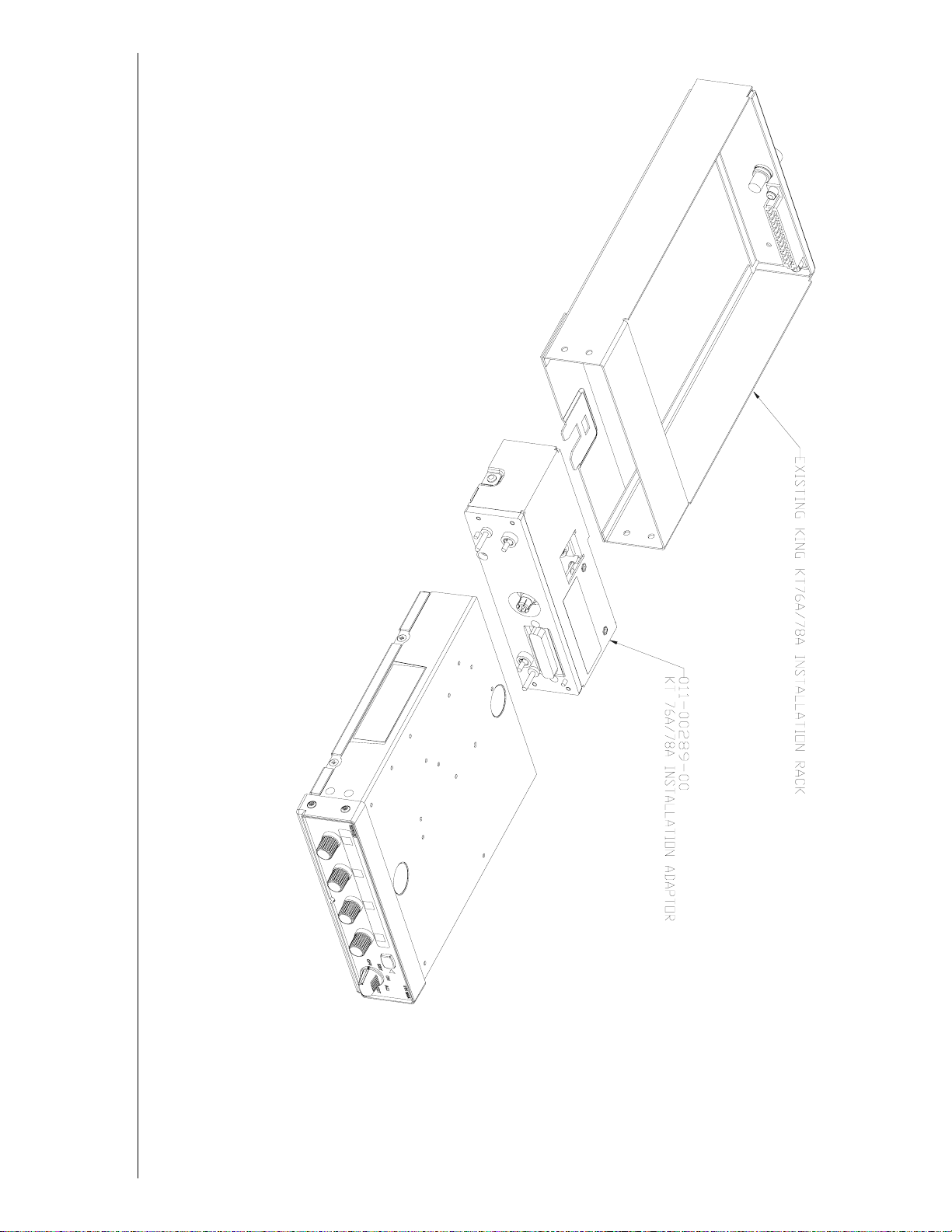
the KT 76A/78A Installation Adapter (P/N 011-00289-00). See figure B7 for the Bendix/King KT 76A/78A
Adapter assembly drawing.
NOTES
GTX 320 units that are at Mod Level 1 must use the Mod Level 1 Bendix/King KT 76A/78A
Installation Adapter. After Mod Level 1, the GTX 320 sits 0.17" (4.3 mm) closer to the instrument
panel. Also, when installing the GTX 320 in an existing Bendix/King KT 76A/78A rack (using the
KT 76A/78A Adapter) and when the aircraft has a bus voltage of +28 VDC, make sure the +28
VDC dropping resistor is bypassed.
A. Attach the KT 76A/78A installation adapter to the rear of the GTX 320 using the two captive
screws on the adapter.
B. Looking at the bottom of the transponder, make sure the front lobe of the locking mechanism is in a
vertical position. This can be accomplished by using a 3/32" Allen wrench through the face plate.
C. Slide the unit into the rack until the front lobe of the unit touches the rack. Guide pins on the back
plate will help in the proper alignment of the unit in the rack.
D. Turn the Allen wrench clockwise until unit is secured in the rack. Continue turning until tight. Do
not overtighten the screw.
E. To remove the unit from the rack, turn the 3/32" Allen wrench counterclockwise until it disengages
from the rack.
GTX 320/320A Installation Manual Page 13
190-00133-01 Rev L
Page 18
3. POST INSTALLATION CONFIGURATION & CHECKOUT PROCEDURE
3.1 AIRCRAFT STATION LICENSING REQUIREMENTS
The Telecommunications Act of 1996, effective February 8, 1996, provides the FCC discretion to eliminate radio
station license requirements for aircraft and ships. At the present time, you do not need an individual license to
operate the GTX 320/320A aboard your private aircraft in many circumstances. To find out the specific details
on whether you are exempt from licensing, please see FCC Fact Sheet PR 5000 or contact the FCC at
(800)-322-1117.
If an aircraft license is required or desired, contact the FCC at (800)-322-1117 to request form 404, Application
for Aircraft Radio Station License. The FCC also has a fax-on-demand service to provide forms by fax at
(202)-418-0177.
The GTX 320/320A owner accepts all responsibility for obtaining the proper licensing before using the
transponder.
OPERATION
NOTE
The coverage you can expect from the GTX 320/320A is limited to “line of sight”. Low altitude or
aircraft antenna shielding by the aircraft itself may result in reduced range. Range can be improved
by climbing to a higher altitude. It may be possible to minimize antenna shielding by locating the
antenna where dead spots are only noticed during abnormal flight attitudes.
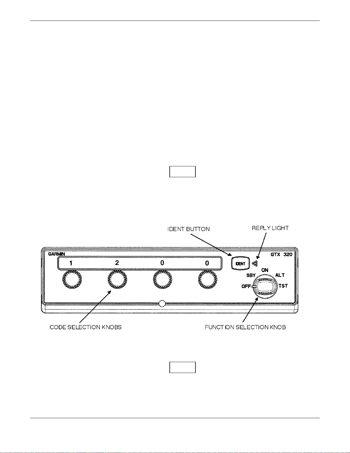
Figure 3-1. Transponder Front Panel (GTX 320 Shown)
NOTE
The Transponder should be turned off before starting aircraft engine(s).
Page 14 GTX 320/320A Installation Manual
Rev L 190-00133-01
Page 19

3.2.1 Function Selection Switches
The function selector switch is a five position rotary switch. The five positions are:
• OFF Turns off all power to the GTX 320/320A.
• SBY Turns the transponder on, but when in SBY the transponder will not reply to any
interrogations from the ground radar system.
• ON Places the transponder in Mode A, the identification mode. In addition to the aircraft’s
identification code, the transponder will also reply to altitude interrogations (mode C) with
signals that do not contain altitude information.
• ALT Places the transponder in Mode A and Mode C, the identification and altitude reporting modes
to respond to ATC aircraft identification interrogations and altitude interrogations with
standard pressure altitude (29.92 inches Hg.) received from an external altitude digital encoder.
The ALT position may be used in aircraft that are not equipped with the optional altitude
encoder, however, the only response will be discreet signals that do not contain altitude
information.
NOTE
Any time the function switch is in the ON or ALT position the transponder becomes an active part of the
beacon system. Select ON or ALT as late as practical prior to takeoff and to OFF or SBY as soon as
practical after completing landing roll unless the change to SBY has been accomplished previously at the
request of ATC.
• TST Turning the switch to the TST position tests the reply indicator. The TST position is spring
loaded and must be held momentarily. When released, it will automatically return to the ALT
position.
3.2.2 Code Selection
The code selector consists of four, eight position switches that provide 4,096 active identification codes.
NOTE
Attention should be paid to the selected identification code. The selected code should be the one
assigned by air traffic control for IFR flight or rules applicable to transponder use for VFR flight.
When making routine code changes, you should avoid inadvertent selection of codes 7500, 7600, or 7700 thereby
causing momentary false alarms at automated ground facilities. For example when switching from code 2700 to
code 7200, switch first to 2200 then 7200, NOT to 7700 and then 7200.
This procedure applies to nondiscrete code 7500 and all discrete codes in the 7600 and 7700 series (i.e., 76007677, 7700-7777) which trigger special indicators in automated facilities. Only nondiscrete code 7500 will be
decoded as the hijack code. An aircraft’s transponder code (when available) is utilized to enhance the tracking
capabilities of the ATC facility, therefore you should not turn the transponder to SBY when making routine code
changes.
GTX 320/320A Installation Manual Page 15
190-00133-01 Rev L
Page 20

Important Codes:
• 1200 The VFR Code for any altitude
• 7600 Loss of Communications
• 7500 Hijack (Never assigned by ATC without prior notification of the pilot that his or her aircraft is
subject to unlawful interference)
• 7700 Emergency
• 7777 Military Interceptor Operations (Never squawk this code.)
• 0000 Military use (Never squawk this code.)
See the Aeronautical Information Manual (AIM) for a detailed explanation of identification codes.
3.2.3 IDENT Button
On occasion, the controller will request “SQUAWK IDENT”. Respond by momentarily pressing and releasing
the IDENT button. Pressing the IDENT button activates the Special Position Identification Pulse (SPI) for
approximately 20 seconds identifying your transponder return from other aircraft on the controller’s scope.
3.2.4 Reply Light
The reply light will blink each time the transponder replies to ground interrogation. The reply light also remains
lit during the IDENT time interval.
Page 16 GTX 320/320A Installation Manual
Rev L 190-00133-01
Page 21

APPENDIX A
CERTIFICATION DOCUMENTS
A.1 Continued Airworthiness
Other than for regulatory periodic functional checks, maintenance of the GTX 320/320A is “on condition” only.
Refer to the GTX 320 and GTX 320A Maintenance Manuals. Periodic maintenance of the GTX 320/320A is not
required.
This section provides assistance to the installing agency in preparing Instructions for Continued Airworthiness
(ICA) in response to Bulletin Number HBAW 98-18, “Checklist for Instructions for Continued Airworthiness for
Major Alterations Approved Under the Field Approval Process”, effective 10/7/98.
Aviation Authority approved installers are hereby granted permission to reference appropriate service
instructions and excerpts from this Installation Manual to accomplish the Instructions for Continued
Airworthiness. This permission does not construe suitability of the documents. It is the applicant’s
responsibility to determine the suitability of the documents for the ICA.
Following is a suggested ICA for a GARMIN GTX 320/320A unit installation. Some of the checklist items do
not apply, in which case they should be marked “N/A” (Not Applicable).
INSTRUCTIONS FOR CONTINUED AIRWORTHINESS, GARMIN GTX 320/320A
1. Introduction
[Aircraft that has been altered: Registration (N-) number, Make, Model and Serial Number]
Content, Scope,
Purpose and Arrangement: This document identifies the Instructions for Continued Airworthiness for the
modification of the above aircraft by installation of a GARMIN GTX 320/320A.
Applicability: Applies to aircraft altered by installation of the GARMIN GTX 320/320A.
Definitions/Abbreviations: None, N/A.
Precautions: None, N/A.
Units of Measurement: None, N/A.
Referenced Publications: GARMIN GTX 320/320A Installation Manual, P/N 190-00133-01
GARMIN GTX 320 Maintenance Manual, P/N 190-00133-02
GARMIN GTX 320A Maintenance Manual, P/N 190-00133-08
GARMIN STC # [applicable STC number for the specific model installed, refer
to Appendix B of this manual].
GARMIN GTX 320/320A Pilot’s Guide, P/N 190-00133-09.
Distribution: This document should be a permanent aircraft record.
2.
Description of the Alteration
Installation of the GARMIN GTX 320/320A, with interface to Encoding Altimeter or Blind Encoder. Refer
to section 2.4 and Appendix B of this manual for interconnect information. Antenna installation, removal
and replacement should be in accordance with applicable provisions of AC43.13-1B and 43.13-2A.
GTX 320/320A Installation Manual Page 17
190-00133-01 Rev L
Page 22

3.
Control, Operation Information
Refer to the GTX 320/320A Pilot’s Guide.
4.
Servicing Information
N/A
5.
Maintenance Instructions
Maintenance of the GTX 320/320A is ‘on condition’ only. Periodic maintenance is not required. Refer to
the GTX 320 and the 320A Series Maintenance Manuals.
6.
Troubleshooting Information
Refer to the GTX 320 and the GTX 320A Maintenance Manuals.
7.
Removal and Replacement Information
Refer to section 2.4 of this manual. If the unit is removed and reinstalled, a functional check of the
equipment should be conducted in accordance with section 3.2 of this manual.
8.
Diagrams
Refer to Appendix B of this manual.
9.
Special Inspection Requirements
N/A
10.
Application of Protective Treatments
N/A
11.
Data: Relative to Structural Fasteners
Antenna installation, removal and replacement should be in accordance with applicable provisions of
AC43.13-1A and 43.13-2A. Also, refer to section 2.3 of this manual.
12.
Special Tools
N/A
13.
This Section is for Commuter Category Aircraft Only
A.
Electrical loads: Refer to section 1.3 of this manual.
B. Methods of balancing flight controls: N/A.
C. Identification of primary and secondary structures: N/A.
D. Special repair methods applicable to the airplane: Antenna installation, removal, and replacement should
be in accordance with applicable provisions of AC43.13-1B and 43.13-2A.
14.
Overhaul Period
No additional overhaul time limitations.
15.
Airworthiness Limitation Section
N/A.
Page 18 GTX 320/320A Installation Manual
Rev L 190-00133-01
Page 23

16.
Revision
To revise this ICA, a letter must be submitted to the local FSDO with a copy of the revised FAA Form 337,
and revised ICA. The FAA inspector accepts the change by signing Block 3 and including the following
statement:
“The attached revised/new Instructions for Continued Airworthiness (date ______) for the above aircraft or
component major alteration have been accepted by the FAA, superseding the Instructions for Continued
Airworthiness (date ______).”
17.
Assistance
Flight Standards Inspectors have the resources to respond to questions regarding the ICA.
Implementation and Record Keeping
For major alterations performed in accordance with FAA field approval policy, the owner/operator operating
under Part 91 is responsible for ensuring that the ICA is made part of the applicable section 91.409 inspection
program for their aircraft. This is accomplished when a maintenance entry is made in the aircraft’s maintenance
record in accordance with section 43.9. This entry records the major alteration and identifies the original ICA
location (e.g., Block 8 of FAA Form 337, dated ______) along with a statement that the ICA is now part of the
aircraft’s inspection/maintenance requirements.
GTX 320/320A Installation Manual Page 19
190-00133-01 Rev L
Page 24

A.2 ENVIRONMENTAL QUALIFICATION FORM
NOMENCLATURE: GTX 320 Airborne ATC Transponder Equipment
TYPE/MODEL/PART NO.: 010-00135-00/10 TSO - C74c Class 1A
MANUFACTURER'S SPECIFICATION AND/OR OTHER APPLICABLE SPECIFICATION: 004-00042-00
MANUFACTURER: GARMIN INTERNATIONAL
ADDRESS: 1200 E 151st St, Olathe, KANSAS 66062
Conditions RTCA DO-160C
Section
Description of Conducted Tests
Temperature and Altitude 4.0 Equipment tested to Categories A1 & D1 except
as noted
Low Temperature 4.5.1
High Temperature 4.5.2. & 4.5.3
In-Flight Loss of Cooling 4.5.4 Cooling air not required
Altitude 4.6.1
Decompression 4.6.2
Overpressure 4.6.3
Temperature Variation 5.0 Equipment tested to Category C
Humidity 6.0 Equipment tested to Category A
Shock 7.0 Equipment tested according to DO-160C, Par.
7.2.1
Operational 7.2
Crash Safety 7.3
Vibration 8.0 Equipment tested without shock mounts to
Categories B, M and N (Table 8-1)
Explosion 9.0 Equipment identified as Category X, no test
required
Waterproofness 10.0 Equipment identified as Category X, no test
required
Fluids Susceptibility 11.0 Equipment identified as Category X, no test
required
Page 20 GTX 320/320A Installation Manual
Rev L 190-00133-01
Page 25

Conditions RTCA DO-160C
Section
Description of Conducted Tests
Sand and Dust 12.0 Equipment identified as Category X, no test
required
Fungus 13.0 Equipment identified as Category X, no test
required
Salt Spray 14.0 Equipment identified as Category X, no test
required
Magnetic Effect 15.0 Equipment tested to Class Z
Power Input 16.0 Equipment tested to Category B
Voltage Spike 17.0 Equipment tested to Category A
Audio Frequency
18.0 Equipment tested to Category B
Susceptibility
Induced Signal
19.0 Equipment tested to Category A
Susceptibility
Radio Frequency
20.0 Equipment tested to Category U
Susceptibility
Radio Frequency Emission 21.0 Equipment tested to Category Z
Lightning Induce Transient
Susceptibility
22.0 Equipment identified as Category XXXX, no test
required
Lightning Direct Effects 23.0 Equipment identified as Category X, no test
required
Icing 24.0 Equipment identified as Category X, no test
required
Other Tests
Remarks- None
GTX 320/320A Installation Manual Page 21
190-00133-01 Rev L
Page 26

A.3 ENVIRONMENTAL QUALIFICATION FORM
Nomenclature: GTX320A Airborne ATC Transponder Equipment
Type/Model/Part No.: 010-00247-( ) TSO - C74c Class 1A
(Includes 011-00728-( ))
Manufacturer's Specification And/Or Other Applicable Specification: 004-00111-00
Manufacturer: GARMIN Corporation
Address: 1200 E 151st St., Olathe, Kansas 66062
Conditions RTCA DO-160D
Section
Description of Conducted Tests
Temperature and Altitude 4.0 Equipment tested to Categories A1 & D1
Low Temperature 4.5.1
High Temperature 4.5.2. & 4.5.3
In-Flight Loss of Cooling 4.5.4 Cooling Air Not Required
Altitude 4.6.1
Decompression 4.6.2
Overpressure 4.6.3
Temperature Variation 5.0 Equipment tested to Category C
Humidity 6.0 Equipment tested to Category A
Shock 7.0 Equipment tested to Category B
Vibration 8.0 Equipment tested in each aircraft type to aircraft
zone 2. Aircraft Type 2 and 6 were tested to
Category S2, Vibration level B2. Aircraft Type 3, 4
and 5 were tested to Category S, Vibration level M.
Note: Vibration level M modified to increase level
to RTCA DO-160C Curve N for Helicopters as
follows-0.1 inches peak-to-peak double amplitude
from 5 Hz to 17 Hz, 1.5 g-Pk from 17 Hz to 500 Hz.
Explosion 9.0 Equipment identified as Category X, no test required
Waterproofness 10.0 Equipment identified as Category X, no test required
Fluids Susceptibility 11.0 Equipment identified as Category X, no test required
Sand and Dust 12.0 Equipment identified as Category X, no test required
Fungus 13.0 Equipment identified as Category X, no test required
Page 22 GTX 320/320A Installation Manual
Rev L 190-00133-01
Page 27

Conditions RTCA DO-160D
Section
Description of Conducted Tests
Salt Spray 14.0 Equipment identified as Category X, no test required
Magnetic Effect 15.0 Equipment tested to Class Z
Power Input 16.0 Equipment tested to Category A
Voltage Spike 17.0 Equipment tested to Category A
Audio Frequency
18.0 Equipment tested to Category B
Susceptibility
Induced Signal
19.0 Equipment tested to Category A
Susceptibility
Radio Frequency
Susceptibility
20.0 Equipment tested for conducted susceptibility to
Category T, radiated susceptibility to Category T,
and pulse test to Category T.
Radio Frequency Emission 21.0 Equipment tested to Category B, Equipment tested
to Category M up to 2 GHz.
Lightning Induced
Transient Susceptibility
22.0 Equipment identified as Category XXXX, no test
required
Lightning Direct Effects 23.0 Equipment identified as Category X, no test required
Icing 24.0 Equipment identified as Category X, no test required
Electrostatic Discharge 25.0 Equipment identified as Category X, no test required
Remarks- None
GTX 320/320A Installation Manual Page 23
190-00133-01 Rev L
Page 28

APPENDIX B
ASSEMBLY AND INSTALLATION DRAWINGS
B.1 GENERAL
This section contains the following installation drawings:
• B1, GTX 320/320A Outline Drawing
• B2, GTX 320/320A Connector/Rack Kit Assembly Drawing
• B3, GTX 320/320A Recommended Panel Cutout Dimensions
• B4, GTX 320/320A Interconnect Wiring Diagram
• B5, Dual Transponder Interconnect Wiring Diagram
• B6, NARCO AT 150 Installation Adapter Assembly Drawing
• B7, KING KT 76A/78A Adapter Assembly Drawing
Page 24 GTX 320/320A Installation Manual
Rev L 190-00133-01
Page 29
GTX 320/320A Installation Manual Page 25 (Page 26 blank)
190-00133-01 Rev L
Figure B1 GTX 320/320A OUTLINE DRAWING
Page 30
GTX 320/320A Installation Manual Page 27 (Page 28 blank)
190-00133-01 Rev L
SEE NOTE
NOTE:
KIT WILL INCLUDE EITHER ITEM 6 OR ITEM 12.
REFER TO SECTION 2 FOR ADDITIONAL INFORMATION.
THESE HOLES
SEE NOTE
12
6
10
NOT USED
2
4
Figure B2 GTX 320/320A CONNECTOR/RACK KIT ASSEMBLY DRAWING
5
8
1
11
3
7
NOT SHOWN
NOT SHOWN
NOT SHOWN
SEE NOTE
SEE NOTE
9
342
1
211-63234-12
212-20014-00
232-00013-01
SCREW, 4-40X.75, FLHP, SS/P
WSHR, FLAT, NON-STD, SS
SNAP RING, EXT, 7/16
ITEM
PART NUMBER
011-00338-00 CONNECTOR/R ACK KIT
DESCRIPTION
RF ADAPTER12 330-00326-00 1
11
10
125-00046-00
234-10002-00
NUT PLATE, D-SUB, 25 POSITION
SPRING WASHER
987
211-60234-06
115-00285-00
125-00032-02
SCREW, 4-40X.187, PHP, SS/P
INSTALL RACK
BACK PLATE
336-00022-00
336-00023-00
312-00005-05
CONT. SCKT, MIL CRP, SIZE 20
CONT, SCKT, MIL CRP, SIZE 20-18
TUBING, HT SHRINK
6
5 330-00184-25
330-00198-00
330-00220-25
BACKSHELL, D-SUB, METAL, 25 POS.
CONN., D-SUB, MIL CRP, SCKT, 25
CONN, BNC, MALE BLINDMATE
1
1255
114
1
1
2.3IN.
1
QTY
211
Page 31
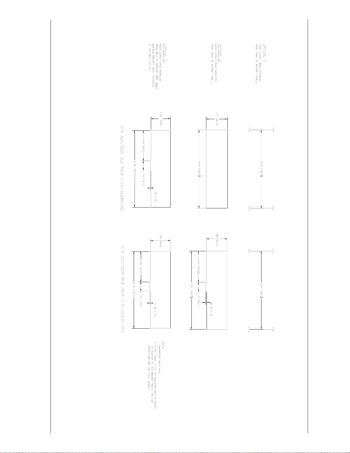
GTX 320/320A Installation Manual Page 29 (Page 30 blank)
190-00133-01 Rev L
Figure B3 GTX 320/320A RECOMMENDED PANEL CUTOUT DIMENSIONS
Page 32
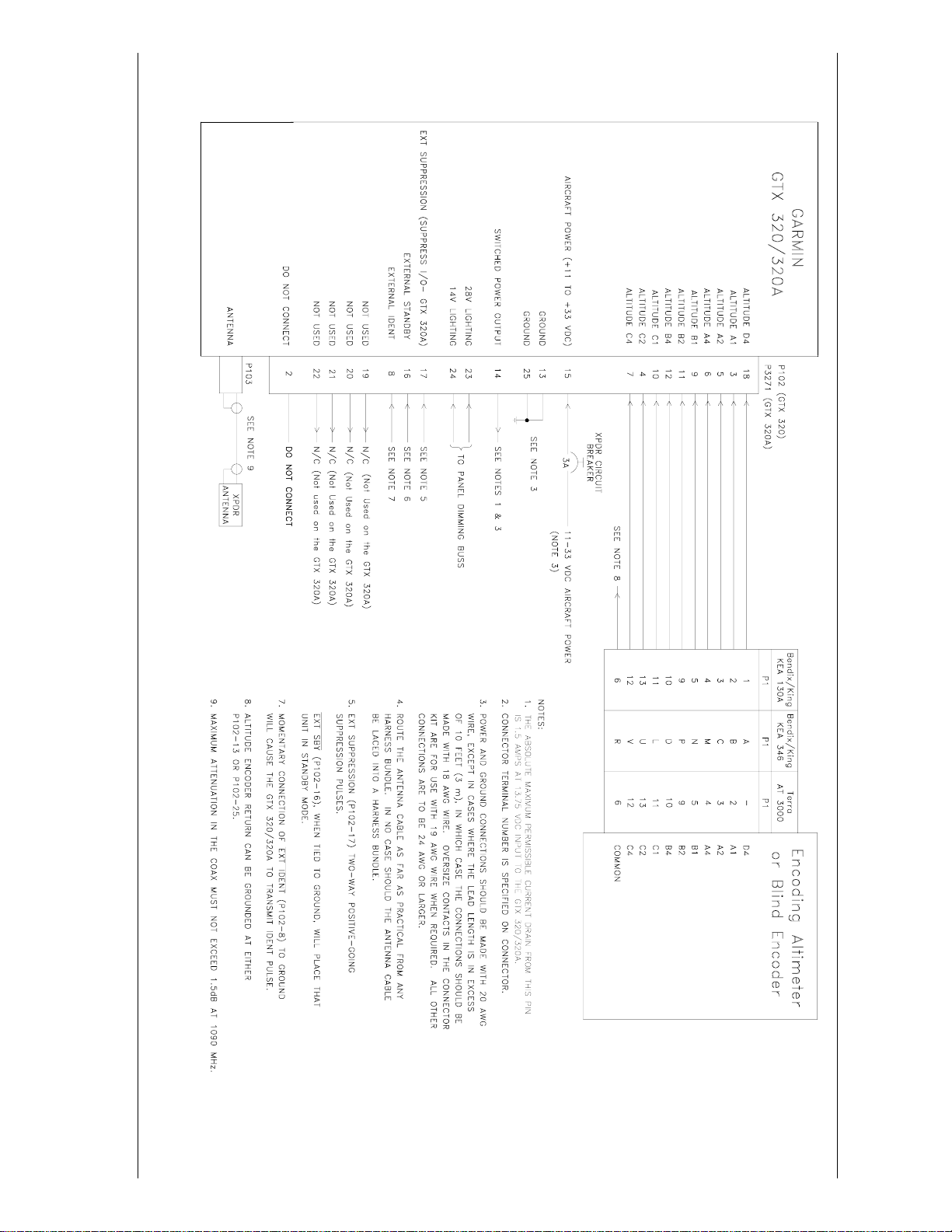
GTX 320/320A Installation Manual Page 31 (Page 32 blank)
190-00133-01 Rev L
Figure B4 GTX 320/320A INTERCONNECT WIRING DIAGRAM
Page 33
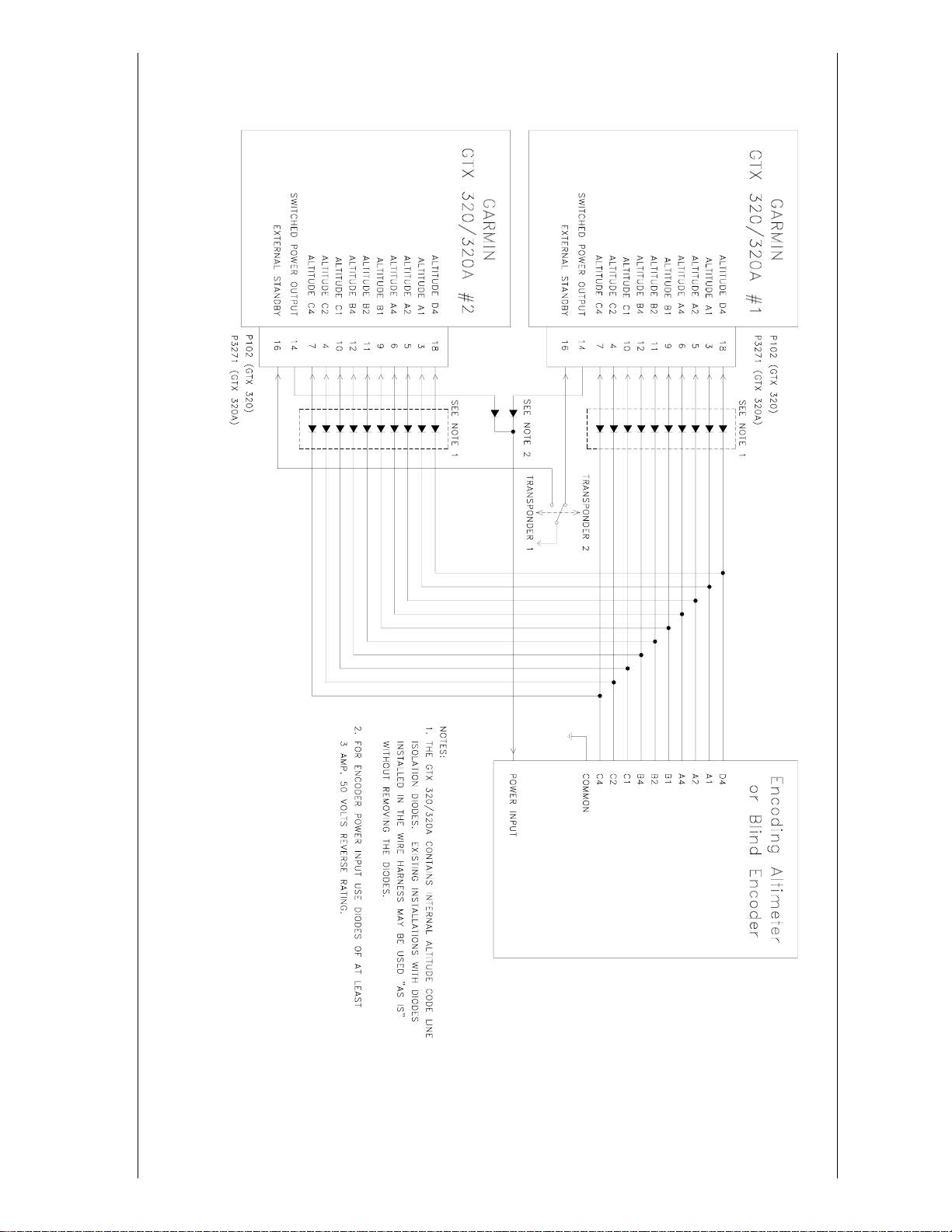
GTX 320/320A Installation Manual Page 33 (Page 34 blank)
190-00133-01 Rev L
Figure B5 GTX 320/320A DUAL TRANSPONDER INTERCONNECT WIRING DIAGRAM
Page 34
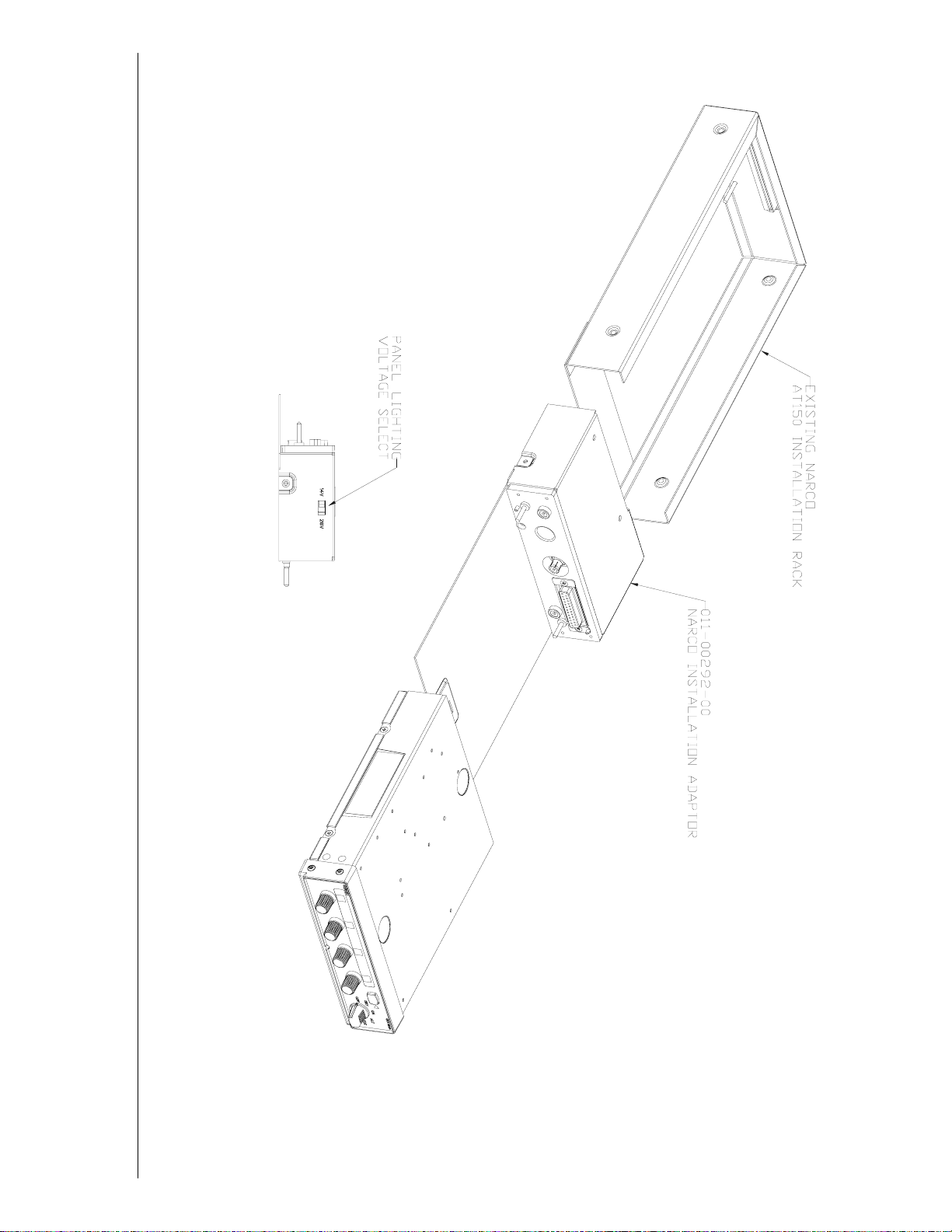
GTX 320/320A Installation Manual Page 35 (Page 36 blank)
190-00133-01 Rev L
Figure B6 NARCO AT 150 INSTALLATION ADAPTER ASSEMBLY DRAWING
Page 35
GTX 320/320A Installation Manual Page 37 (Page 38 blank)
190-00133-01 Rev L
Figure B7 KING KT 76A/78A ADAPTER ASSEMBLY DRAWING
Page 36

APPENDIX C
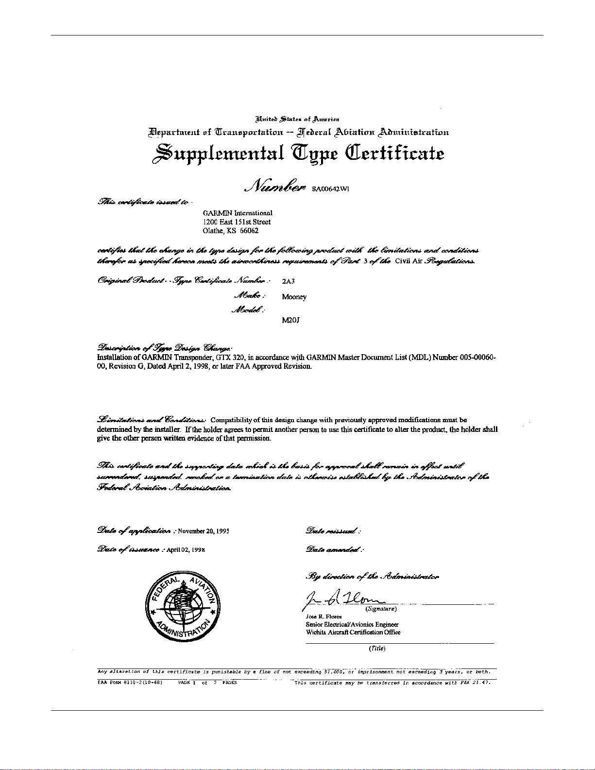
STC PERMISSION
Consistent with N8110.69 or Order 8110.4, Aviation Authority approved installations are hereby granted
permission to use STC # SA00642WI data to modify aircraft.
GTX 320/320A Installation Manual Page 39
190-00133-01 Rev L
Page 37
Page 40 GTX 320/320A Installation Manual
Rev L 190-00133-01
 Loading...