

Page 1
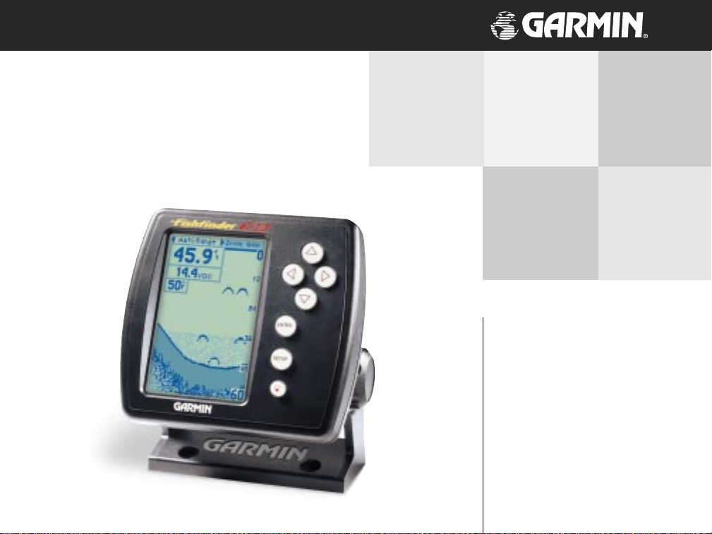
Fishfinder 100
owner’s
manual
Page 2

© 1999 GARMIN Corporation
GARMIN International, Inc.
1200 East 151st Street, Olathe, Kansas 66062, U.S.A.
Tel. 913/397.8200 or 800/800.1020
Fax 913/397.8282
GARMIN (Europe) Ltd.
Unit 5, The Quadrangle, Abbey Park Industrial Estate, Romsey, SO51 9AQ, U.K.
Tel. 44/1794.519944
Fax 44/1794.519222
GARMIN (Asia) Corporation
No. 68, Jangshu 2nd Road, Shijr, Taipei County, Taiwan
Tel. 886/2.2642.9199
Fax 886/2.2642.9099
All rights reserved. Except as expressly provided herein, no part of this manual may be reproduced, copied, transmitted, disseminated, downloaded
or stored in any storage medium, for any purpose without prior written consent of GARMIN Corporation. GARMIN Corporation hereby grants
permission to download a single copy of this manual onto a hard drive or other electronic storage medium to be viewed for personal use, provided
that such electronic or printed copy of this manual contains the complete text of this copyright notice and provided further that any unauthorized
commercial distribution of this manual is strictly prohibited.
Information in this manual is subject to change without notice. GARMIN
Corporation reserves the right to change or improve its products and to make changes in the content without obligation to notify any person or
organization of such changes. Visit the GARMIN website (www.garmin.com) for current updates and supplemental information concerning the use
and operation of this and other GARMIN products.
GARMIN and Fishfinder 100 are registered trademarks of GARMIN Corporation and may not be used without the express permission of GARMIN
Corporation.
December 1999 Part Number 190-00173-00 Rev. A Printed in Taiwan
Page 3
Thank You for choosing the GARMIN Fishfinder 100. This product is
designed for easy operation and to provide years of reliable service.
Please take the time to read this Owner’s Manual, and learn the
operation of your new unit. This will help ensure that you get the most
from the Fishfinder 100.
If you encounter a problem, or just have a question, contact or Product
Support Department at 913-397-8200, Monday — Friday 8:00 a.m. to
5:00 p.m. Central Time.
Enjoy you new Fishfinder 100 and once again thank you for choosing
GARMIN.
our on-line registration today!
number of your Fishfinder 100 handy and connect
to our website (www.garmin.com). Look for the
Product Registration link on the Home page.
GARMIN product purchase using a mail-in
registration card, we invite you to re-register using
our NEW on-line system. Many services provided
by our new product registration system are now
being automated and re-registering your purchase
ensures you the best possible support from
GARMIN.
Introduction
Customer Service
Product Registration
Help us better support you by completing
Have the serial
Why should you register your Fishfinder 100?
• Notification of Product Updates
• Notification of New Products
• Lost or Stolen unit tracking
NOTE: If you have previously registered your
i
Page 4
GARMIN Corporation warrants this product to be free from defects in
materials and manufacture for one year from the date of purchase.
Introduction
Limited Warranty
ii
GARMIN will, at its sole option, repair or replace any components that fail
in normal use. Such repairs or replacement will be made at no charge to
the customer for parts or labor. The customer is, however, responsible for
any transportation costs. This warranty does not cover failures due to
abuse, misuse, accident or unauthorized alteration or repairs.
THE WARRANTIES AND REMEDIES CONTAINED HEREIN ARE
EXCLUSIVE AND IN LIEU OF ALL OTHER WARRANTIES EXPRESS OR
IMPLIED OR STATUTORY, INCLUDING ANY LIABILITY ARISING UNDER
ANY WARRANTY OF MERCHANTABILITY OR FITNESS FOR A PARTICULAR
PURPOSE, STATUTORY OR OTHERWISE. THIS WARRANTY GIVES YOU
SPECIFIC LEGAL RIGHTS, WHICH MAY VARY FROM STATE TO STATE.
IN NO EVENT SHALL GARMIN BE LIABLE FOR ANY INCIDENTAL,
SPECIAL, INDIRECT OR CONSEQUENTIAL DAMAGES, WHETHER
RESULTING FROM THE USE, MISUSE, OR INABILITY TO USE THIS
PRODUCT OR FROM DEFECTS IN THE PRODUCT. SOME STATES DO
NOT ALLOW THE EXCLUSION OF INCIDENTAL OR CONSEQUENTIAL
DAMAGES, SO THE ABOVE LIMITATIONS MAY NOT APPLY TO YOU.
To obtain warranty service, call the GARMIN Customer Service department (913-397-8200) for a returned merchandise tracking number. The unit
should be securely packaged with the tracking number clearly marked on the
outside of the package and sent freight prepaid and insured to a GARMIN
warranty service station. A copy of the original sales receipt is required as the
proof of purchase for warranty repairs. GARMIN retains the exclusive right
to repair or replace the unit or software or offer a full refund of the purchase
price at its sole discretion. SUCH REMEDY SHALL BE YOUR SOLE AND
EXCLUSIVE REMEDY FOR ANY BREACH OF WARRANTY.
Page 5
The Fishfinder 100 Standard Package contains the following items:
• Fishfinder 100
• Surface/Flush Mount Kit
• Wiring Adapter Cable
• Owner’s Manual
• Quick Reference Guide
• *Transom Mount Transducer (w/depth/temp)
* Optional
Optional Transducers:
010-10251-00 Trolling Motor Mount Adapter
010-10252-00 Speed Sensor
010-10107-00 Bronze Thru-Hull (w/depth/temp)
010-10249-00 Plastic Transom Mount (w/depth/temp)
010-10119-00 Plastic Thru-Hull (w/depth)
010-10177-00 Bronze Thru-Hull (w/depth/temp/speed)
010-10224-00 Plastic In-Hull (depth only)
010-10225-00 Remote Temperature Sensor
Accessories:
010-10170-00 10’ Transducer Extension Cable
010-10170-01 20’ Transducer Extension Cable
010-10269-00 Protective Front Cover
Introduction
Packaging and Accessories
iii
Page 6
Introduction ....................................................................... i-viii
Customer Service ................................................................................................ i
Introduction
Limited Warranty .............................................................................................. ii
Packaging and Accessories ................................................................................ iii
Unit Display ..................................................................................................... vi
Installation .......................................................................... 1-9
Table of Contents
Selecting A Transducer ...................................................................................... 1
Transom Mount Installation ............................................................................... 2
In-hull Installation ............................................................................................. 3
Trolling Motor Installation ................................................................................. 4
Wiring Harness Installation ............................................................................... 5
Wiring to a Fuse Block ................................................................................... 5-6
Display Installation (Surface Mount) ................................................................. 7
Display Installation (Flush Mount) .................................................................... 8
Testing the Installation ...................................................................................... 9
Unit Operation ................................................................ 12-27
Using the Adjustment Bar
Range ............................................................................................................... 12
Zoom ............................................................................................................... 13
View ................................................................................................................ 13
Gain ................................................................................................................. 14
Setup Menu
Chart
Whiteline ......................................................................................................... 16
Scroll Speed ..................................................................................................... 16
Scale ................................................................................................................ 17
Tools
Noise Reject ..................................................................................................... 18
Flasher ............................................................................................................. 19
Simulator ......................................................................................................... 19
Numbers
Number Size .................................................................................................... 20
Battery Voltage ................................................................................................. 20
Temperature .................................................................................................... 21
Speed ............................................................................................................... 21
iv
Page 7
Alarms
Fish Alarm ....................................................................................................... 22
Shallow Water ................................................................................................. 22
Deep Water...................................................................................................... 23
Battery Voltage ................................................................................................. 23
System
Contrast ........................................................................................................... 24
Beeper ............................................................................................................. 24
NMEA Output ................................................................................................. 24
Calibration
Keel Offset ....................................................................................................... 25
Water Type ....................................................................................................... 25
Units
Depth .............................................................................................................. 26
Temperature .................................................................................................... 26
Speed ............................................................................................................... 26
Memory
Remember ....................................................................................................... 27
Factory Setup .................................................................................................. 27
Software Version .............................................................................................. 27
On the Water ................................................................... 28-33
Understanding Sonar ....................................................................................... 28
Transducer Coverage ....................................................................................... 29
Understanding the Chart ................................................................................. 30
Whiteline ......................................................................................................... 31
Thermoclines ................................................................................................... 32
Simulator Mode ............................................................................................... 33
Appendix ......................................................................... 28-33
Appendix A—Specfications ............................................................................. 34
Appendix B—Alarm Messages and Icons ......................................................... 35
Appendix C—Fishfinder 100 Portable ....................................................... 36-37
Appendix D—Index ....................................................................................... 38-
Introduction
Table of Contents
v
Page 8
Introduction
What can the Fishfinder 100
Display?
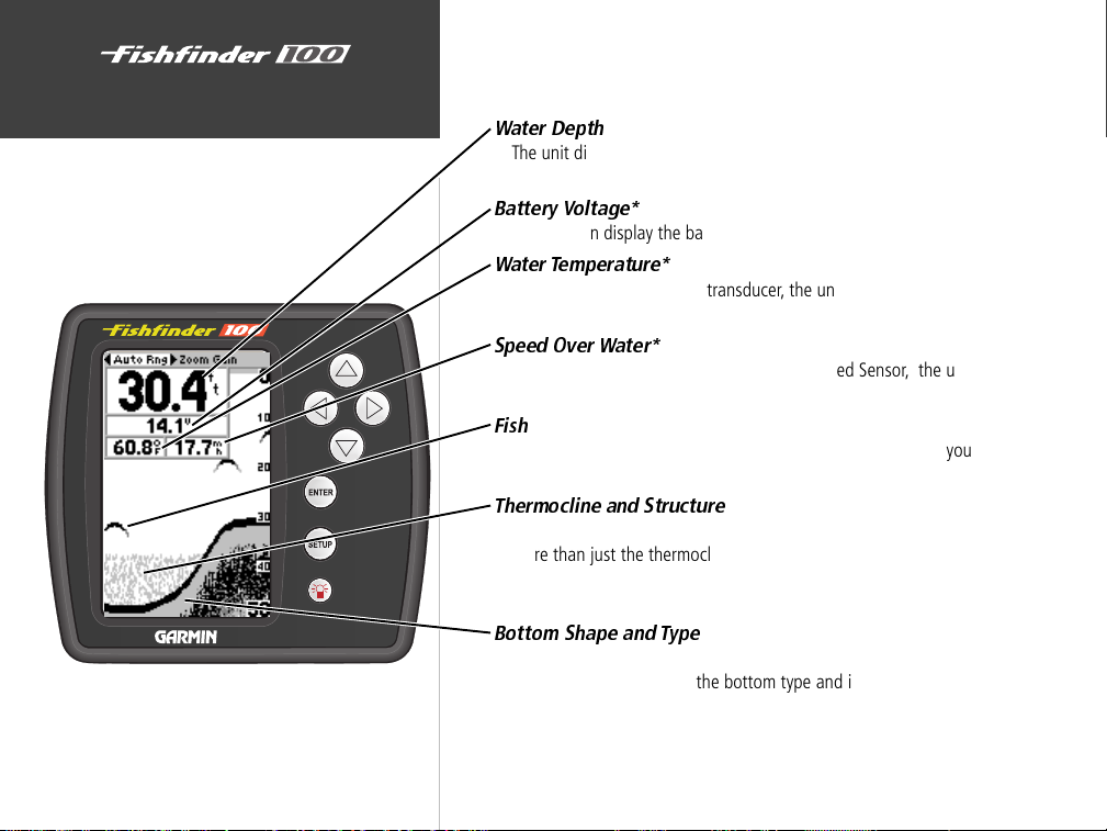
The Fishfinder 100 is able to display a variety of useful information
about the underwater environment. Below are a few things the unit will
help you see.
Water Depth
The unit displays water depth and can provide a warning for shallow or
deep-water conditions.
Battery Voltage*
The unit can display the battery voltage that is available to the unit.
Water T emperatur e*
If equipped with a capable transducer, the unit can display the water
temperature.
Speed Over Water*
If equipped with a capable transducer or Speed Sensor, the unit can
display the boat’s speed over water.
Fish
The unit displays fish as arches or fish symbols and can alert you when
a fish is detected.
Thermocline and Structure
With GARMIN’s See-Thru technology the Fishfinder 100 can display
more than just the thermocline and structure, the unit displays fish in
and below the thermocline, trees, brush and deadfall like you have
never seen before!
Bottom Shape and Type
Garmin’s unique DCG (Depth Control Gain) system provides a clear
graphic representation of the bottom type and its shape.
* requires optional transducer or sensor
vi
Page 9
Transducers
The transducer acts as the eyes and ears of your new sonar. Proper
transducer selection and installation are critical to the operation of your
unit.
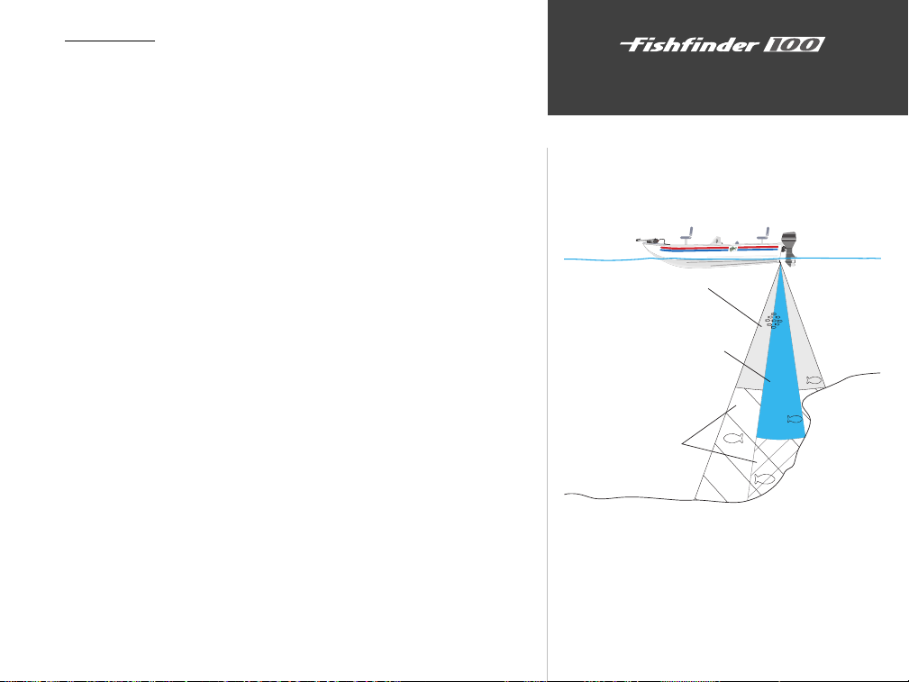
The transducer transmits sound waves toward the bottom in a cone
shape. The larger the cone angle the larger the coverage area at a given
depth. While it is good to see as large of an area as possible, it is best to
select a transducer that suits the water that you are on.
A wide cone angle transducer works best in shallow water. The wide
cone angle provides a large coverage area, but at a decreased bottom
resolution. In deeper water this can result in a large dead zone where fish
cannot be seen.
A narrow cone angle transducer is better suited to deep-water
installations. The narrow cone angle provides a smaller viewing area
(compared to a wide cone angle transducer at the same depth) with
improved bottom resolution and a smaller dead zone.
Included in the Optional Package is a 20° cone angle, temperature
sensing, transom mount transducer. This transducer provides good allaround performance. A variety of optional transducers are available from
your local dealer or GARMIN.
Installation
Selecting a Transducer
Wide cone angle
Narrow cone angle
dead zone
fish not seen
X
X
1
Page 10
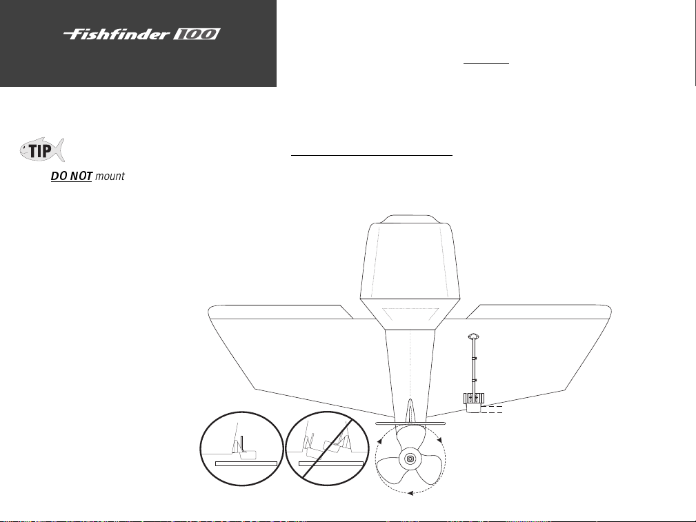
Installation
Mounting the Transducer
DO NOT
mount the transducer behind
strakes, struts, fittings, water intake or
discharge ports, or anything that creates
air bubbles or causes the water to become
turbulent. It is important that the
transducer be in clean (non turbulent)
water for optimal performance.
2
Proper transducer installation is key to getting the best performance
from your new unit. If the transducer lead is too short, extension cables are
available from you GARMIN dealer. DO NOT cut the transducer lead, this
will void your warranty.
Following are some tips and basic installation instructions for three
popular transducers. Detailed installation instructions are provided in the
transducer kits.
Transom Mount Installation
010-10248-00 (depth/temp) Transom Mount Transducer.
Apply marine sealant to all
screw threads to prevent water
from seeping into the transom.
OK
Mount the transducer parallel with the bottom.
Mount the transducer cable cover
well above the waterline.
Transducer should extend 1/8" below
fiberglass hull or 3/8" below aluminum hull
Make sure that the transducer is
below water level when the boat
is on plane at high speed
Do not mount transducer directly in the
path of the prop. The transducer can cause
cavitation that may degrade the boat's performance
and damage the prop.
Page 11

In-hull Installation
The 010-10224-00 transducer is designed to be mounted inside a
fiberglass hull. The standard plastic transom mount transducer can also be
mounted in this fashion using this method. If using a temperature sensing
transducer, the temperature displayed will reflect the hull temperature.
Selecting a Location
1. The location has to be solid fiberglass, devoid of any air bubbles,
laminates, fillers or dead air space. The location needs to be in an area
of clean water at all speeds. Do not place the transducer over any
strakes or behind any obstruction on the hull that would create
turbulence at speed.
Many modern hulls have a prelocated pocket for In-hull transducer
installation. If you are unsure if your hull is equipped with a prelocated
pocket, contact your hull manufacturer.
Testing the Location
Place the transducer in the water, pointed directly at the bottom and set
unit for optimum performance. Place the transducer in the test device as
show on the side bar. If the sonar performance is significantly
degraded, another location will need to be tested.
Installing the Transducer
1. Lightly sand the surface of the hull and face of the transducer with 400
grit wet or dry sandpaper.
2. Build a dam using strip caulk about 1/4” tall. Pour about 1/8” of two
part, slow cure epoxy in the dam. Place the transducer in the epoxy,
turning the transducer to work out any air bubbles.
3. Weight the transducer in place and allow to cure for 24 hours.
Installation
Mounting the Transducer
Weight
transducer to
hold it in place
Strip Caulk or
RTV Sealer
Hull Surface
Apply twisting
motion to eliminate
any trapped air
bubbles
Installing the Transducer
PVC Pipe
or a Can
Testing the Location
Weight transducer in place
for at least 24 hours
Fill Pipe or Can
with water or a
light mineral oil
Slow cure two
part epoxy
Strip Caulk or
RTV Sealer Dam
3
Page 12
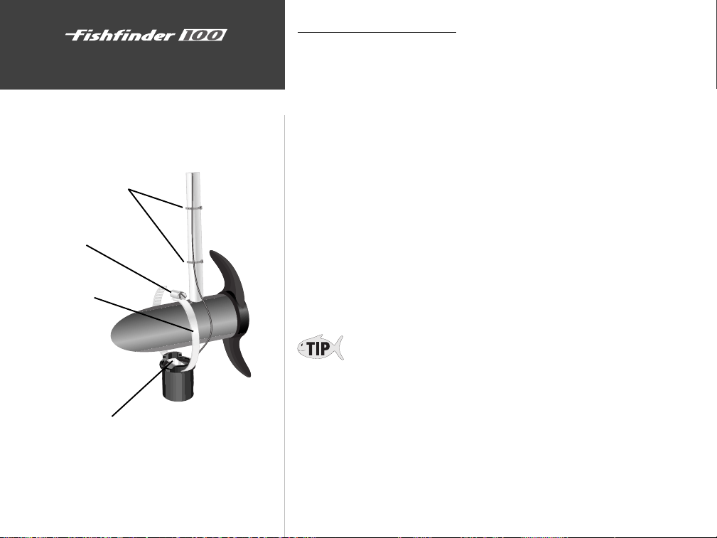
Installation
Mounting the Transducer
Cable Ties
Worm Gear
Clamp Band
Slide clamp band through slots on transducer
Trolling Motor Installation
Included in the 010-10251-00 transducer kit you should have:
1. Worm Gear Clamp
2. Cable Ties
3. Transducer
Mounting the Transducer:
1. Loosen the Worm Gear Clamp until end of the band is clear of the worm
gear.
2. Slide the clamp band through the slots on the transducer.
3. Place the free end of the clamp band into the worm gear and tighten
until the band is through the worm gear.
4. Place the clamp and transducer over the body of the trolling motor.
Finish tightening the clamp to secure the transducer to the trolling
motor.
5. Secure the transducer cable to the trolling motor shaft using the
supplied cable ties.
If you are experiencing interference while the trolling motor is
operating, try installing the transducer cable at right angles to the
trolling motor power cables.
4
Page 13
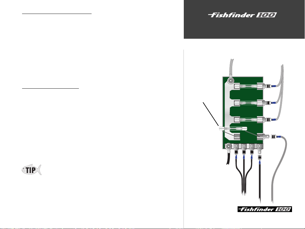
Wiring Harness Installation
The Fishfinder 100 comes with a wiring harness that connects the unit
to power and the transducer with one easy-to-remove connection. Make
sure the wiring harness will reach the unit before beginning installation.
If it is necessary to extend the power/data wires, use a wire of comparable size and keep your extension as short as possible.
If the transducer lead is too short, DO NOT cut the transducer lead to
lengthen the cable. This will void the warranty. Transducer extension
cables are available in 10’ or 20’ lengths from your GARMIN dealer.
Installation
Installing the Wiring Harness
10-18 Volt Boat Supply
Wiring to a Fuse Block
If your boat has an electrical system, it may be possible to wire the unit
directly to an unused holder on your current fuse block. If you are using
Install 2-Amp Fuse
the boat’s fuse block, remove the in-line fuse holder supplied with the unit.
Installing the Wiring Harness:
1. Determine the polarity of the fuse holder using a Test Light or Volt Meter.
2. Install the Red (+) wire on the Positive Fuse Holder Terminal.
3. Install the Black (-) wire on the Negative Fuse Holder Terminal.
4. Install a 2 amp fuse in the Fuse Holder.
During a typical installation, only the Red and Black wires are used. The
Blue wire supplies NMEA data, and doesn’t have to be connected for
normal operation of the unit.
Continued on page 6
+
2A
-
Boat Ground
Red Wire
Black Wire
5
Page 14
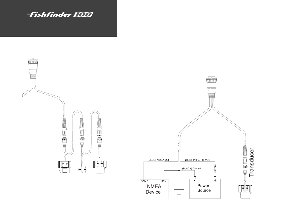
Installation
Installing the Wiring Harness
Power/Data
Connection
Wiring Harness Installation (continued)
If your boat does not have a fuse block, the unit can be wired directly
to the battery. Make sure the 2-Amp in-line fuse supplied with the unit is
installed.
The Fishfinder 100 can be connected to another piece of NMEA
compatible electronic equipment. If equipped with a capable transducer,
the Fishfinder 100 sends depth, temperature and speed information that
could be displayed on another device.
Speed Temp Transducer
Connecting a Transducer to Multiple Sensors
6
2-Amp In-Line Fuse
Page 15
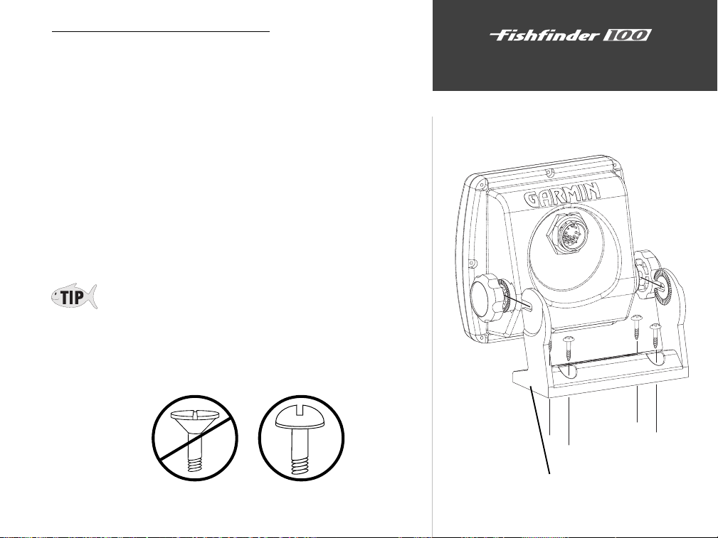
Display Installation (Surface Mount)
The Fishfinder 100 can be mounted to a flat surface using the supplied
Surface Mounting Bracket.
Installation
Surface Mounting the Display:
1. Position the Surface Mount in the desired location. Leave approximately
2'’ behind the unit for cable clearance.
2. Mark the location of the four mounting holes with a pencil.
3. Drill pilot holes for the mounting fasteners (not included in kit).
4. Secure the Surface Mount, using the mounting fasteners.
5. Slip the unit into the surface mount bracket.
6. Tighten the knobs to secure the unit to the bracket.
The Surface Mount Bracket is designed to be secured using a flat head
screw. If you use a screw with a countersunk head you risk damaging
the Surface Mount Bracket.
OK
Installing the Display
Surface Mount Bracket
7
Page 16
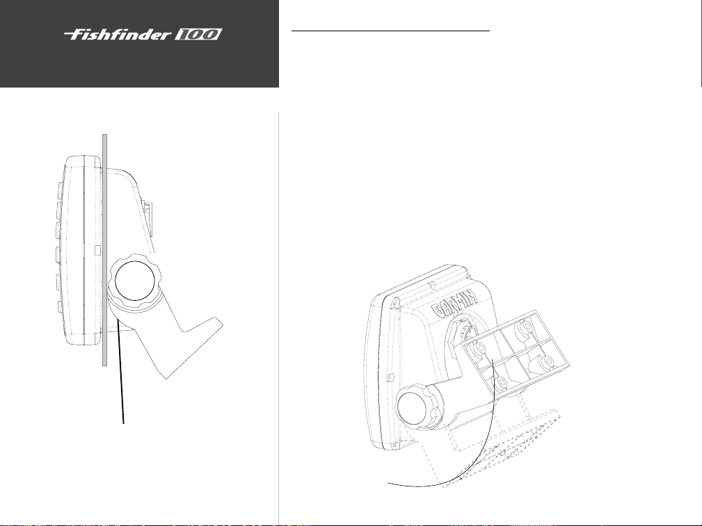
Installation
Installing the Display
Display Installation (Flush Mount)
The Fishfinder 100 can be mounted flush against the dash or electron-
ics rack that is no more than 1/4” thick.
Flush Mounting the Display:
1. Remove the Surface Mount Bracket and Knobs.
2 Cut a 4.3”W x 4.35”H relief hole where the unit will be mounted.
3. Place the display in the relief hole and tape in place.
4. Reinstall the knobs in the unit. Install the surface mount with the cam
lobes pointed toward the unit.
5. Rotate the surface mounting bracket forcing the cam lobes to pull the
unit tight against the surface. Tighten the knobs.
Pull bracket down until cam lobe contacts surface
8
Page 17
Testing the Installation
While it is possible to perform some checks with the boat trailered, to
properly test the installation the boat should be in the water.
Press the Power button and the Fishfinder 100 should power on. If
the unit fails to power on, verify that the wiring adapter is seated properly
in the back of the unit, the Red and Black wires are connected to the correct
polarity, and that the 2-Amp fuse is installed and not blown. If the unit is
connected to a power supply that exceeds 18 VDC, a ‘Battery Voltage High’
warning will be displayed and the unit will turn off.
As the unit powers on, it should immediately start showing the bottom.
Verify that the unit is not in the simulator mode. If the unit is in the
simulator mode, make sure that the transducer is connected to the wiring
harness.
To test the transducer installation, gradually increase the boat speed
while checking the unit operation. If the unit displays intermittently or
fails to display, verify that the transducer is aligned parallel with the bottom
and if necessary, adjust the transducer height until the unit operates
correctly. It may be necessary to make several adjustments to ensure proper
operation throughout the speed range.
When adjusting the depth of the transducer, make the adjustments in
small increments. Placing the transducer too deep can adversely affect
the boat’s performance and place the transducer at greater risk of
striking underwater objects.
Installation
Unit Operation
Testing the Installation
9
Page 18
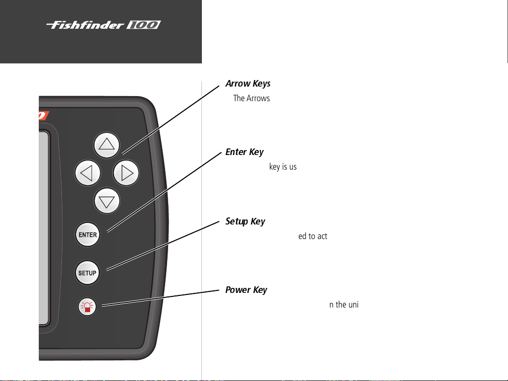
Unit Operation
10
Keypad Function
Arrow Keys
The Arrows Keys are used to select items on the Adjustment Bar and
Setup menu and to change field data.
Enter Key
The Enter key is used to activate/deactivate Adjustment Bar and Setup
Menu data fields for review or change
Setup Key
The Setup key is used to activate/deactivate Setup Menu.
Power K e y
The Power Key is used to turn the unit on/off and to activate the
display backlight.
Page 19
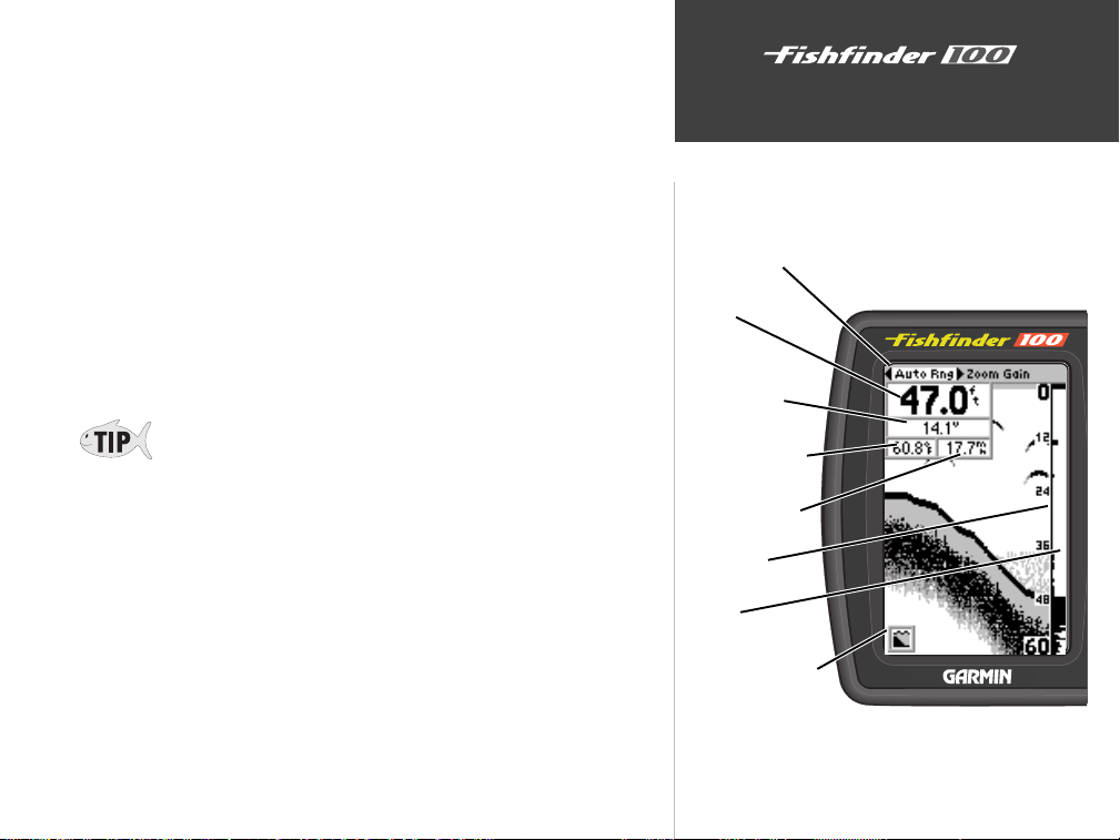
At the top left of the display you will find the Adjustment Bar and a
variety of user-selectable information including Depth, Battery Voltage, Water
Temperature, and Speed Over Water. To provide data on Water Temperature
and Speed Over Water, the Fishfinder 100 requires a transducer capable of
producing the particular data.
The Depth Scale and the Flasher Function are displayed from top to
bottom along the right side of the display. Messages and Alarm Icons are
displayed along the bottom.
The Fishfinder 100 has three levels of display backlighting, Off, Low
and High. The backlight is activated by momentarily pressing the Power
key. To change the backlight level, press the Power key repeatedly.
If the unit is unable to track the bottom for any reason, the digits in the
depth window will flash on and off to alert the user that the unit is not
tracking the bottom.
Unit Operation
Describing The Display
Adjustment Bar
Depth
Battery Voltage
Water Temperature
Speed Over Water
Depth Scale
Flasher
Alarm/Message Icons
11
Page 20
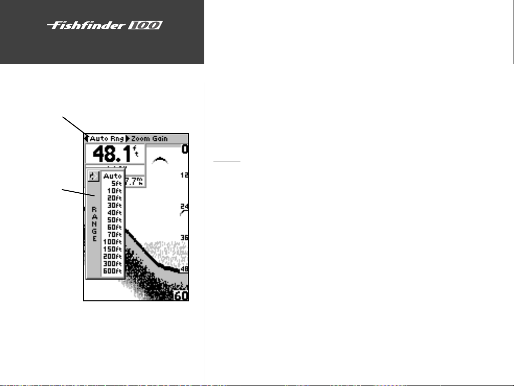
The Adjustment Bar
Current Setting
Adjustment List
Unit Operation
Using the Adjustment Bar
The Adjustment Bar allows direct access to the settings most commonly
changed while using the unit. These include the depth Range, Zoom setting,
and the Gain (sensitivity) of the unit.
Place the highlight (white bar) over the desired selection using the
RIGHT or LEFT Arrow key and the current setting will be displayed in the
highlight. To immediately change the setting, press the UP or DOWN
Arrow key. If you wish to review the available settings before making a
change, press the ENTER key to activate the adjustment list.
Range
The Range Adjustment is used to set the display depth range. The unit
can be set to automatically track the bottom or set to a user-specified range.
To select a Range:
1. Highlight ‘Range’ on the Adjustment Bar.
2. Using the UP or DOWN Arrow, place the pointer at the desired range.
Setting the unit to automatically track the bottom:
1. Highlight ‘Range’ on the Adjustment Bar.
2. Using the UP or DOWN Arrow, select ‘Auto’ at the top of the adjustment list
12
Page 21
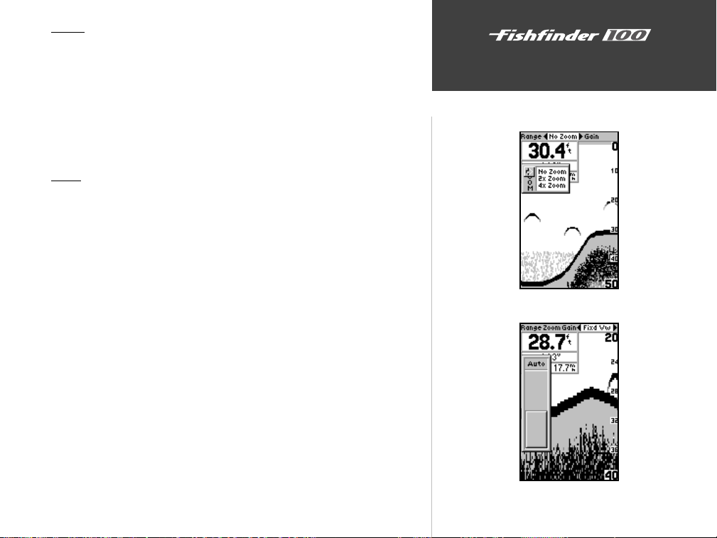
Zoom
The Zoom Adjustment is used to quickly select a display zoom scale.
To change the zoom scale:
1. Highlight ‘Zoom’ on the Adjustment Bar.
2. Using the UP or DOWN Arrow, select the desired display zoom level.
When a scale other than ‘No Zoom’ is selected, the Adjustment Bar will
display a new selection labeled View.
View
The View Adjustment is available only when a Zoom Scale other than
‘No Zoom’ is selected. This setting allows you to select a specific area to
view on the display or allow the unit to automatically select a viewing area
based on the bottom.
To change the view:
1. Highlight ‘View ‘on the Adjustment Bar.
2. Press the UP or DOWN arrows to change the setting.
To have the unit automatically set a view:
1. Highlight ‘View’ on the Adjustment Bar
2. Using the UP or DOWN Arrow, move the slider to the top or bottom of
the range then release and press the Arrow again.
Unit Operation
The Adjustment Bar
Zoom Adjustment
View Adjustment
13
Page 22
Unit Operation
The Adjustment Bar
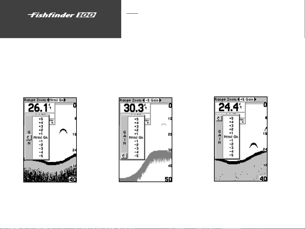
Gain
The Gain Adjustment allows the user to control the sensitivity of the
unit’s receiver. This provides some flexibility in what is seen on the display.
To see more detail, increase the receiver sensitivity by selecting a higher gain
(+). If there is too much detail or if the screen is cluttered, lowering the
sensitivity (-) may increase the clarity of the display.
To change the Gain:
1. Highlight ‘Gain’ on the Adjustment Bar.
2. Using the UP or DOWN Arrows, move the pointer to the desired setting.
14
Minimum Gain
Mid Range Gain Maximum Gain
Page 23
Setup Menu
The Setup Menu contains the unit settings that should not require
frequent change. The Setup Menu is divided into eight tabs Chart, Tools,
Numbers, Alarms, System, Calibrations, Units, and Memory . Each tab will be
described in more detail in this section.
To enter and exit the Setup Menu, press the SETUP button on the face
of the unit. The first time that the SETUP button is pressed, the Setup
Menu will be displayed with the ‘Chart’ tab highlighted in black. Pressing
the UP or DOWN arrow will move the highlight between the tab selections.
Press the RIGHT arrow to access the selection fields. Each time the Setup
Menu is accessed, the unit will return to the last edited selection field. Press
the LEFT arrow key to get back to the tabs.
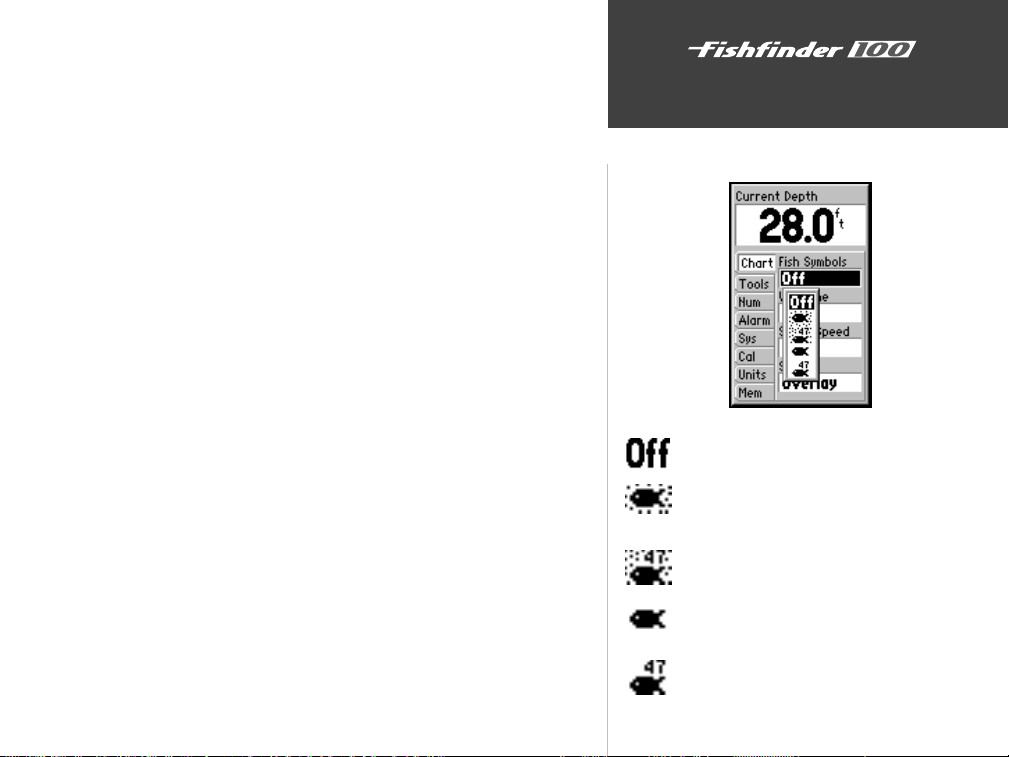
Chart
The ‘Chart’ tab allows the user to determine the appearance of the
scrolling chart display. To access the ‘Chart’ tab place the highlight over it
using the arrow keys.
Fish Symbols
‘Fish Symbols’ allows the user to determine how the chart will display
underwater targets and background information. If ‘Fish Symbols’ are
set to ‘OFF’, the unit will display all of the available information about
the underwater environment. If a fish symbol is selected, the chart will
display only the information related to that symbol.
To select a Fish Symbol:
1. Highlight the ‘Chart’ tab on the Setup Menu.
2. Highlight the ‘Fish Symbol’ selection field and press ENTER.
3. Using the UP or DOWN arrow select the desired symbol and press ENTER.
Unit Operation
Setup Menu/Chart
Fish Symbols
— All available information will be displayed.
— Suspended targets will display as symbols. In this mode
background information will still be displayed making
fish identification easier.
— Same as above with target depth displayed.
— Suspended targets displayed as symbols. No background
information will be displayed in this mode.
— Same as above with target depth displayed.
15
Page 24
Unit Operation
Setup Menu/Chart
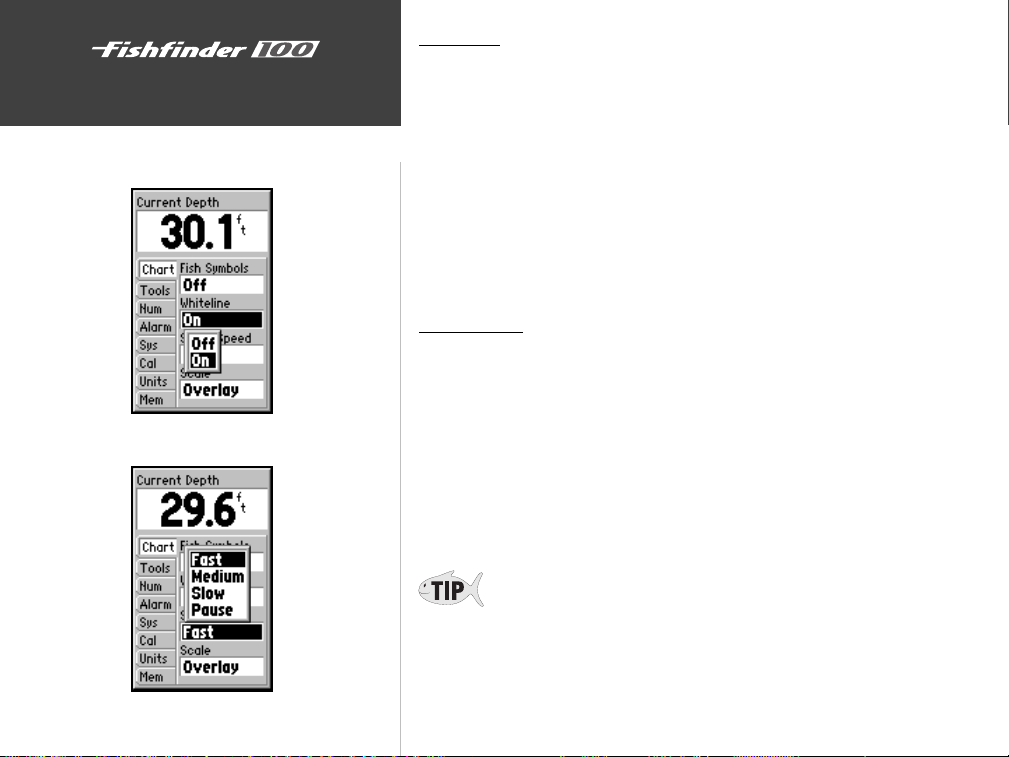
Whiteline Selections
Whiteline
‘Whiteline’ controls how the unit displays information about the
bottom type (hard or soft). With the Whiteline ‘OFF’, the bottom return
will display as black and contain no information on bottom hardness. With
Whiteline ‘ON’, the bottom return will become gray scaled and can be used
to determine bottom hardness. See page 31 for more detail on this feature.
To Change the Whiteline Setting:
1. Highlight the ‘Chart’ tab on the Setup Menu.
2. Highlight the ‘Whiteline’ selection field and press ENTER.
3. Choose ‘ON’ or ‘OFF’ and press ENTER to accept the selection.
Scroll Speed
The speed that the chart scrolls from right to left can be adjusted using
the ‘Scroll Speed’ selection field. If you are sitting still, or the chart is
moving too fast slowing the scroll rate can be beneficial.
To Adjust the Scroll Speed:
1. Highlight the ‘Chart’ tab on the Setup Menu.
2. Highlight the ‘Scroll Speed’ selection field and press ENTER.
3. Choose ‘Fast’, ‘Medium’, ‘Slow’ or ‘Pause’, press ENTER to accept the
selection.
16
If you are using the Fishfinder 100 on the portable case battery power,
slowing the scroll rate will help to conserve your battery.
Scroll Speed Selections
Page 25
Scale
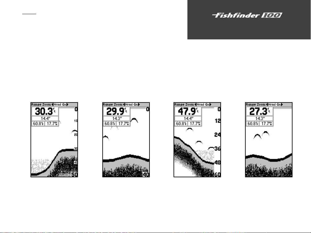
The depth ‘Scale’ is displayed vertically along the right side of the
chart. The depth ‘Scale’ can be configured to display four different ways:
as an ‘Overlay’, in the ‘Corners’, with ‘Basic’ or ‘No Scale’.
To Change the Scale Setting:
1. Highlight the ‘Chart’ tab on the Setup Menu.
2. Highlight the ‘Scale’ selection field and press ENTER.
3. Choose ‘Overlay’, ‘Corners’, ‘Basic’ or ‘No Scale’, press ENTER to
accept the selection.
Scale —
Overlay
Scale —
Corners
Scale —
Basic
Unit Operation
Setup Menu/Chart
Scale —
No Scale
17
Page 26
Unit Operation
Setup Menu/Tools
Tools
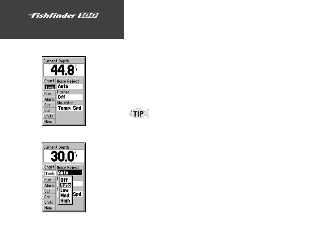
The Tools tab contains the ‘Noise Reject’, ‘Flasher’, and ‘Simulator’
tools. The ‘Noise Reject’ and ‘Flasher’ tools are used to enhance the chart
and help in identifying and providing information about an underwater
return. The ‘Simulator’ tool is used to enhance the simulator mode by
allowing you customize the simulated transducer selection. To access the
Tools tab place the highlight over it using the arrow keys.
Noise Reject
The ‘Noise Reject’ tool helps filter unwanted noise from the chart. The
‘Noise Reject’ tool can be turned ‘OFF’, set to ‘AUTO’(automatically) adjust
or to a fixed ‘LOW’, ‘MED’ium or ‘HIGH’ setting.
18
Tools Tab
Noise Reject Selections
Remember when setting the Noise Reject tool, the higher the noise
rejection setting, the more likely the unit is to not show fish or structure.
To Change the Noise Reject Setting:
1. Highlight the ‘Tools’ tab on the Setup Menu.
2. Highlight the ‘Noise Reject’ selection field and press ENTER.
3. Choose ‘Off’, ‘Auto’, ‘Low’, ‘Med’, or ‘High’, press ENTER to accept the
selection.
Page 27
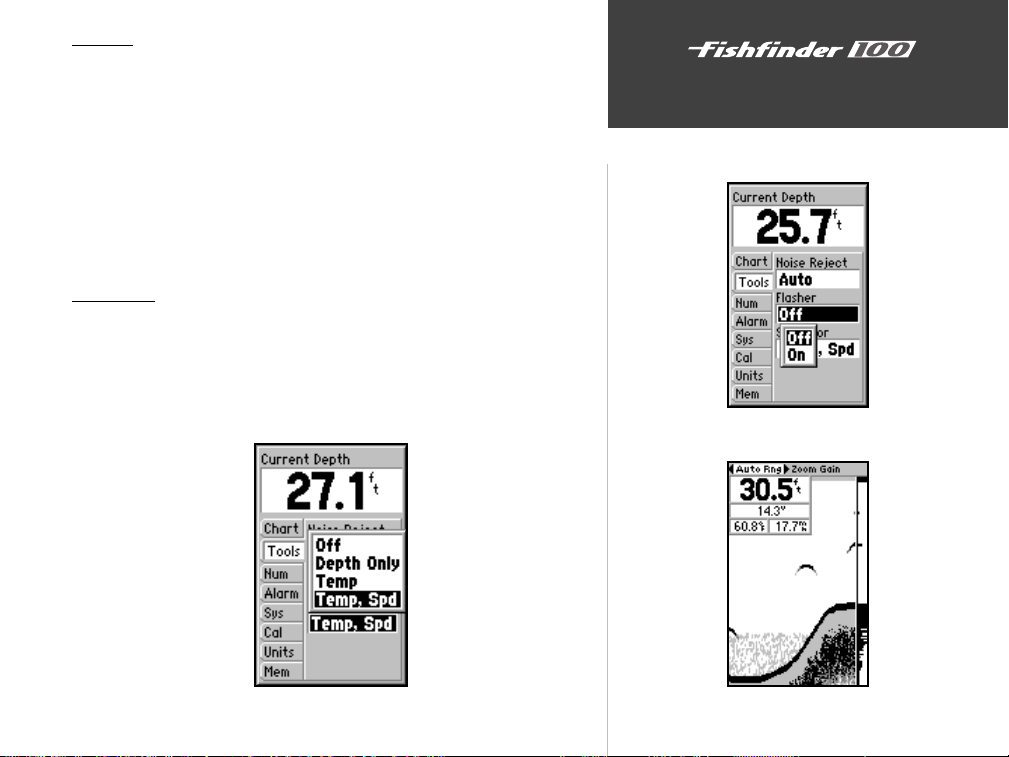
Flasher
With the ‘Flasher’ tool active, a graphic Flasher representation will be
displayed on the far right side of the chart. This graphic Flasher displays
structure and bottom returns much the same as a true Flasher. You may
find this feature particularly useful when using ‘Fish Symbols’.
To Turn the Graphic Flasher On and Off:
1. Highlight the ‘Tools’ tab on the Setup Menu
2. Highlight the ‘Flasher’ selection field and press ENTER.
3. Select ‘ON’ or ‘OFF’ and press ENTER to accept the selection.
Simulator
The ‘Simulator’ tool allows you to select a transducer type for use with
the Fishfinder 100’s built in simulator. These choices allow the simulator to
more accurately depict actual operation of the unit. For details on using the
simulator see page 33.
Unit Operation
Setup Menu/Tools
Graphic Flasher Selections
Simulator Transducer Selections
Graphic Flasher Tool
19
Page 28
Unit Operation
Setup Menu/Numbers
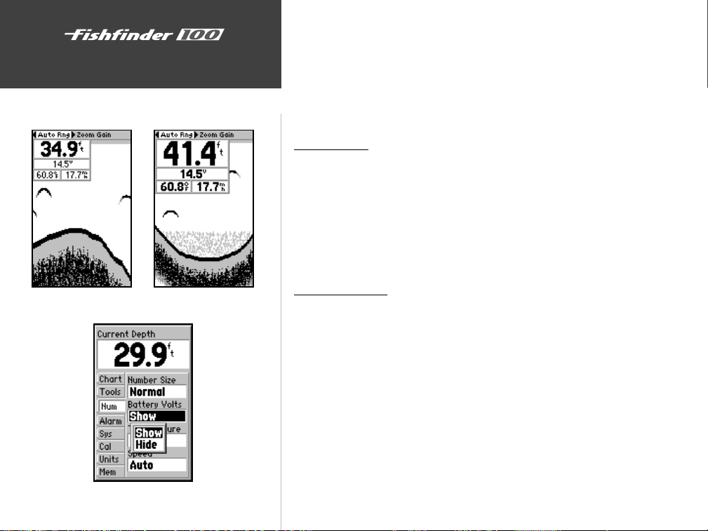
Normal Numbers
Large Numbers
Numbers
The ‘NUM’ (Numbers) tab allows you to choose whether you would
like to see normal or large numbers on the chart. You can also configure
the unit to display ‘Battery Voltage’, (water) ‘Temperature’, and ‘Speed’ Over
Water if the unit is equipped with a capable transducer. To access the
Numbers tab place the highlight over it using the arrow keys.
Number Size
This setting determines the size of the numbers displayed in the
‘Depth’, ‘Temperature’, ‘Battery Voltage’ and ‘Speed’ fields on the chart.
To Select Normal or Large Numbers:
1. Highlight the ‘NUM’ tab on the Setup Menu.
2. Highlight the ‘Number Size’ selection field and press ENTER.
3. Choose ‘Normal’ or ‘Large’, press ENTER to accept the selection.
Battery Voltage
The Fishfinder 100 can display the current battery voltage on the chart.
To Show or Hide the Battery Voltage Display Field:
1. Highlight the ‘NUM’ tab on the Setup Menu.
2. Highlight the ‘Battery Voltage’ selection field and press ENTER.
3. Choose ‘Show’ or ‘Hide’, press ENTER to accept the selection.
20
Battery Voltage Selections
Page 29
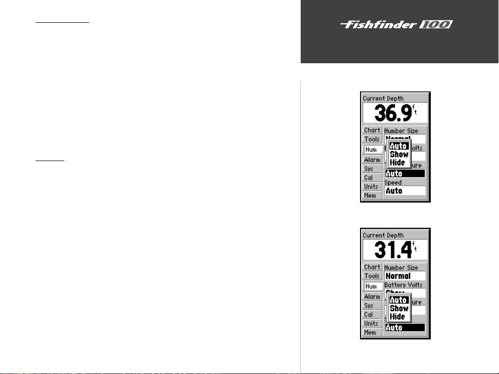
Temperature
The Fishfinder 100 can display the water temperature when equipped
with a temperature sensing transducer. The unit has the ability to
automatically sense when a temperature capable transducer is connected
and display the water temperature. The temperature field can be shown or
hidden regardless of the transducer installed.
To Set the Temperature Display Field:
1. Highlight the ‘NUM’ tab on the Setup Menu.
2. Highlight the ‘Temperature’ selection field and press ENTER.
3. Choose ‘Auto’, ‘Show’ or ‘Hide’, press ENTER to accept the selection.
Speed
The Fishfinder 100 can display the boat’s ‘Speed’ Over Water when
equipped with a speed capable transducer. The unit has the ability to
automatically sense when a capable transducer is connected and display
speed. The ‘Speed’ can be shown or hidden regardlessly of the transducer
installed.
To Set the Speed Display Field:
1. Highlight the ‘NUM’ tab on the Setup Menu.
2. Highlight the ‘Speed’ selection field and press ENTER.
3. Choose ‘Auto’, ‘Show’ or ‘Hide’, press ENTER to accept the selection.
Unit Operation
Setup Menu/Numbers
Temperature Display Selections
Speed Display Selections
21
Page 30
Unit Operation
Alarms
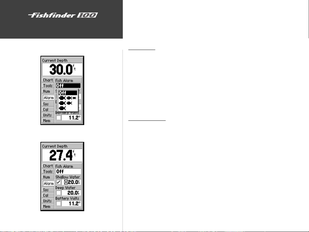
The ‘Alarm’ tab allows you to activate and configure the four alarms
available in the Fishfinder 100. To access the ‘Alarm’ tab place the highlight
over it using the arrow keys. See page 35 for alarm icons and messages.
22
Setup Menu/Alarms
Fish Alarm Selections
Shallow Water Alarm
Fish Alarm
The ‘Fish Alarm’ can be configured to sound by fish size. There are
four different alarm selections: ‘Off’, ‘Small, Medium and Large’, ‘Medium
and Large’, or ‘Large’.
To Select an Alarm:
1. Highlight the ‘Alarm’ tab on the Setup Menu.
2. Highlight the ‘Fish Alarm’ selection field and press ENTER.
3. Choose the desired setting, press ENTER to accept the selection.
Shallow Water
The ‘Shallow Water’ Alarm can be set to sound a warning at a depth
determined by the user. Before the unit will sound a warning the alarm
must be activated.
Activating/Deactivating the Shallow Water Alarm:
1. Highlight the ‘Alarm’ tab on the Setup Menu.
2. Highlight the ‘Shallow Water’ checkbox.
3. Pressing ENTER will insert or remove a check mark in the checkbox.
Setting the Shallow Water Alarm Depth:
1. Highlight the ‘Shallow Water’ Depth Field and press ENTER.
2. Using the arrow keys input the desired depth, press ENTER to accept
the setting.
Page 31
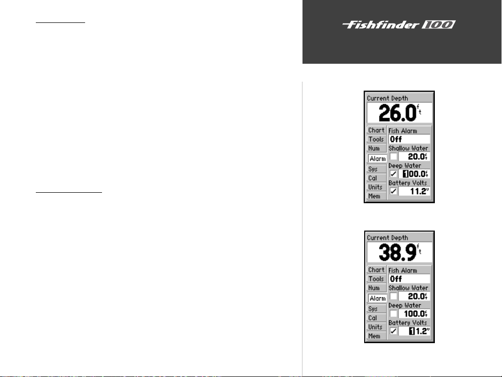
Deep Water
The ‘Deep Water’ Alarm can be set to sound a warning at a depth
determined by the user. Before the unit will sound a warning the alarm
must be activated.
Activating/Deactivating the Deep Water Alarm:
1. Highlight the ‘Alarm’ tab on the Setup Menu.
2. Highlight the ‘Deep Water’ checkbox.
3. Pressing ENTER will insert or remove a check mark in the checkbox.
Setting the Deep Water Alarm Depth:
1. Highlight the ‘Deep Water’ Depth Field and press ENTER.
2. Using the arrow keys input the desired depth, press ENTER to accept
the setting.
Battery Voltage
The ‘Battery Voltage’ alarm can be set to warn you when the battery is
reaching a critical state of discharge.
Activating/Deactivating the Deep Water Alarm:
1. Highlight the ‘Alarm’ tab on the Setup Menu.
2. Highlight the ‘Battery Volts’ checkbox.
3. Pressing ENTER will insert or remove a check mark in the checkbox.
Setting the Battery Volts Alarm:
1. Highlight the ‘Battery Volts’ field and press ENTER.
2. Using the arrow keys input the desired voltage, press ENTER to accept
the setting.
Unit Operation
Setup Menu/Alarms
Deep Water Alarm
Battery Voltage Alarm
23
Page 32
24
Unit Operation
Setup Menu/Alarms
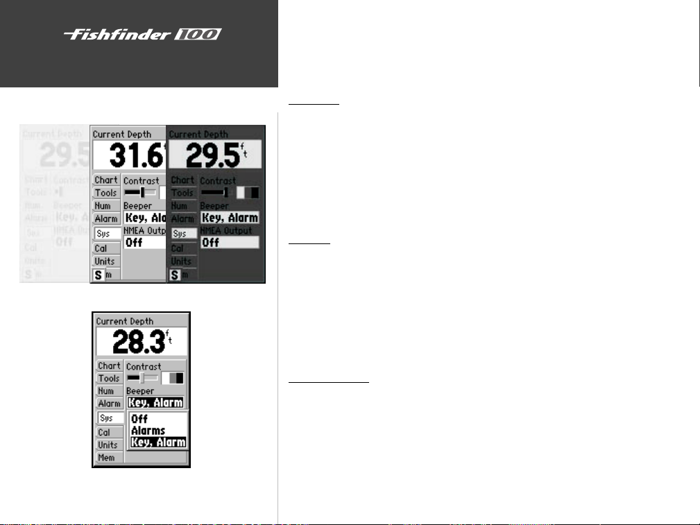
Contrast Adjustment
Beeper Selections
System
The ‘Sys’(System) tab contains the ‘Contrast’, ‘Beeper’, and ‘NMEA’
Output setups. To access the ‘System’ Setup Menu, use the arrow keys to
highlight the System tab.
Contrast
The display ‘Contrast’ may need to be adjusted to compensate for light
levels or viewing angles.
To Adjust the Contrast:
1. Highlight the ‘System’ tab on the Setup Menu.
2. Highlight the ‘Contrast’ Adjustment field and press ENTER.
3. Move the slider using the arrow keys, press ENTER to accept the setting.
Beeper
The ‘Beeper’ field contains three settings: ‘Off’, ‘Alarms Only’, and ‘Key
& Alarm’.
To Change the Beeper Setting:
1. Highlight the ‘System’ tab on the Setup Menu.
2. Highlight the ‘Beeper’ field and press ENTER.
3. Choose ‘Off’, ‘Alarms’, or ‘Key & Alarms’, press ENTER to accept the setting.
NMEA Output
The Fishfinder 100 has the ability to output information about Depth,
Speed, and Water Temp for display on another NMEA-compatible device.
To Activate/Deactivate the NMEA Output:
1. Highlight the ‘System’ tab on the Setup Menu.
2. Highlight the ‘NMEA’ Output field and press ENTER.
3. Choose ‘Off’, or ‘On’, press ENTER to accept the setting.
Page 33
Calibration
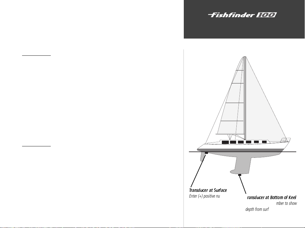
The ‘Cal’ (Calibration) tab contains calibrations fields for ‘Keel Offset’,
and ‘Water Type’ (salt or fresh). These calibrations help to ensure the
Fishfinder 100 will provide the most accurate readings at all times. To
access the ‘Calibration’ tab, use the arrow keys to highlight it.
Keel Offset
The ‘Keel Offset’ field allows the user to offset the surface reading for
the depth of a keel. Enter a positive number to offset for a keel. It is also
possible to enter a negative number to compensate for a large vessel that
may draw several feet of water. The ‘Keel Offset’ will be reflected in the
depth reading.
To Set a Keel Offset:
1. Highlight the ‘Calibration’ tab on the Setup Menu.
2. Highlight the ‘Keel Offset’ field and press ENTER.
3. Using the arrow keys enter a new offset, press ENTER to accept the
new setting.
Water Type
Since sound waves travel through fresh and salt water at different rates
it is necessary to select the ‘Water Type’ to ensure accurate readings on the
unit.
To Change the Water Type:
1. Highlight the ‘Calibration’ tab on the Setup Menu.
2. Highlight the ‘Water Type’ selection field and press ENTER.
3. Choose ‘Fresh’ or ‘Salt’, press ENTER to accept the selection.
Unit Operation
Setup Menu/Calibrations
Transducer at Surface
Enter (+) positive number to
show depth from bottom of
keel
T
ransducer at Bottom of Keel
Enter (-) negative number to show
depth from surface
25
Page 34
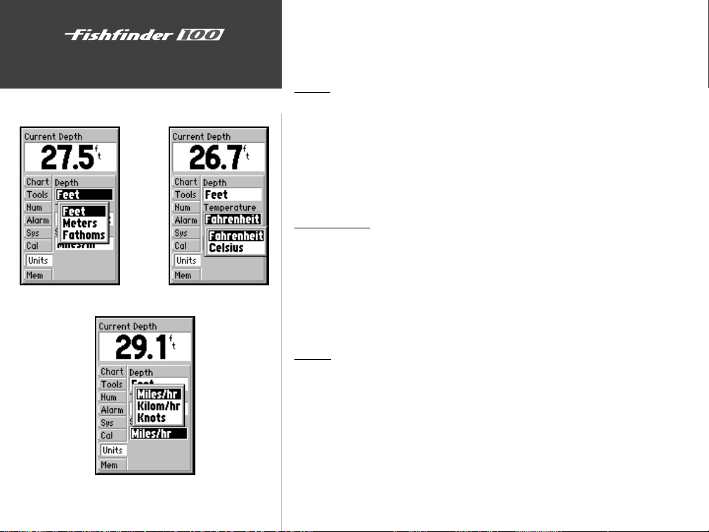
Depth Selections
26
Unit Operation
Setup Menu/Units
Temperature Selections
Speed Selections
Units
The ‘Units’ tab contains settings for ‘Depth’, ‘Temperature’ and ‘Speed’.
To access the ‘Units’ tab, use the arrow keys to highlight it.
Depth
The ‘Depth’ field can be configured to display in Feet (ft), Meters (mt)
or Fathoms (fa).
To Select a Depth Unit:
1. Highlight the ‘Units’ tab on the Setup Menu.
2. Highlight the ‘Depth’ field and press ENTER.
3. Select ‘Feet’, ‘Meters’, or ‘Fathoms’, press ENTER to accept the new setting.
Temperature
If equipped with a temperature capable transducer, the unit can display
water temperature in Fahrenheit (°F) or Celsius (°C).
To Select a Temperature Unit,
1. Highlight the ‘Units’ tab on the Setup Menu.
2. Highlight the ‘Temperature’ field and press ENTER.
3. Select ‘Fahrenheit’ or ‘Celsius’ press ENTER to accept the new setting.
Speed
If equipped with a speed capable transducer, the unit can display the
boat’s ‘Speed’ Over Water. The unit can be configured to display in ‘Nautical
Miles-Per-Hour’ (kt), ‘Kilometers-Per-Hour’ (kh), or ‘Miles-Per-Hour’ (mh).
To Select a Speed Unit:
1. Highlight the ‘Units’ tab on the Setup Menu.
2. Highlight the ‘Speed’ field and press ENTER.
3. Select ‘Miles’, ‘Kilometers’, or ‘Knots’, press ENTER to accept the
selection.
Page 35
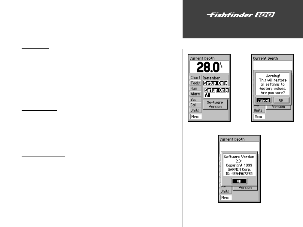
Memory
The ‘Memory’ tab contains the settings for unit memory, allows you to
reset the unit to the factory setup and allows you to review software version
information. To access the ‘Memory’ tab, use the arrow keys to highlight it.
Unit Operation
Remember
The Fishfinder 100 can be set to remember All of the unit settings
including the Adjustment Bar or the items in Setup Only.
To Select a Memory Setting:
1. Highlight the ‘Memory’ tab on the Setup Menu.
2. Highlight the ‘Remember’ field and press ENTER.
3. Choose ‘All’ or ‘Setup Only’, press ENTER to accept the selection.
Factory Setup
To Restore the Factory Settings:
1. Highlight the ‘Memory’ tab on the Setup Menu.
2. Highlight the ‘Factory’ Setup button and press ENTER.
3. Choose ‘OK’ to reset the unit or ‘Cancel’ to abort.
Software Version
The ‘Software Version’ Button will report information about the current
software version that is in the unit.
To Activate the Software Version Window:
1. Highlight the ‘Memory’ tab on the Setup Menu.
2. Highlight the ‘Software Version’ button and press ENTER.
3. Press ENTER to close the information window.
Setup Menu/Memory
Remember Selections
Software Version Information
Reset to Factory Settings
27
Page 36
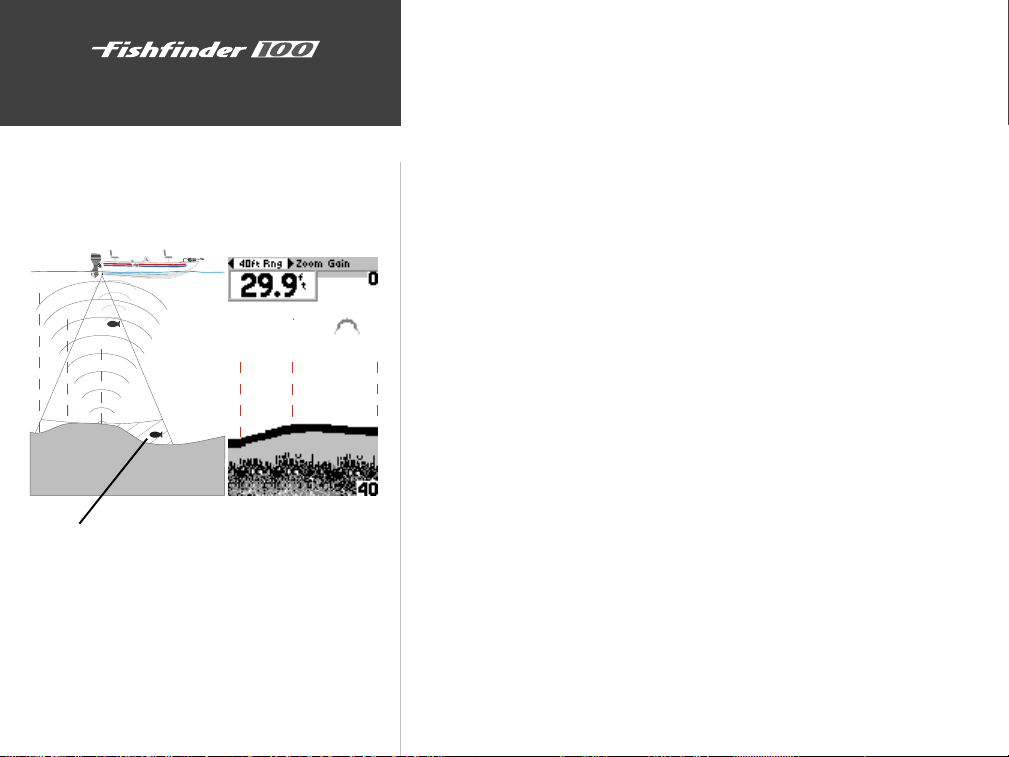
Unit Operation
On the Water
Unit Operation and the Chart
1
2
3
This fish is currently in a Dead Zone and is not detected
by the sonar. The fish is in the coverage area of the
transducer, but remember the first strong return sets the
bottom level. The fish will eventually be detected when
the first strong return sets the bottom level below the
fish.
1
2
Understanding Sonar
If you are familiar with sonar, and can determine what is on the chart,
this section may not be for you. This section is intended to help the novice
user gain some understanding of how the Fishfinder 100 operates and how
it can help improve their fishing productivity.
To understand what the unit is displaying, it is important to have a
general knowledge of how the unit works and how it determines what to
display. Briefly described, the unit operates by transmitting sound waves
toward the bottom of a lake, stream or seabed in a cone shaped pattern.
When a transmitted soundwave strikes an underwater object such as the
bottom, a piece of structure, or a fish, sound is reflected back to the
transducer. The transducer collects the reflected sound waves and sends the
data to the unit to be processed and displayed on the chart. The underwa-
3
ter data is displayed on the chart in the order that it is returned: first
returned—first on the chart. The diagram in the sidebar demonstrates this
showing an underwater scene as it would be displayed on the chart.
Generally speaking, if the only thing between the transducer and the
bottom is water, the first strong return will come from the bottom directly
below the transducer. The first strong return sets the bottom level. Weaker
secondary returns provide the detailed data. Stronger returns will display
in darker colors, black being the strongest return. In Example 2 (page 30)
you can see that the branches and the fish were the strongest secondary
returns and are indicated in black on the display.
That is brief description of how your Fishfinder operates. Let’s take a
look at how this data can help you to improve your fishing.
28
Page 37
Transducer Coverage
4"
10"
15"
20"
25"
30"
35"
40"
45"
45"
3'
6'
9'
12'
15'
18'
21'
24'
27'
30'
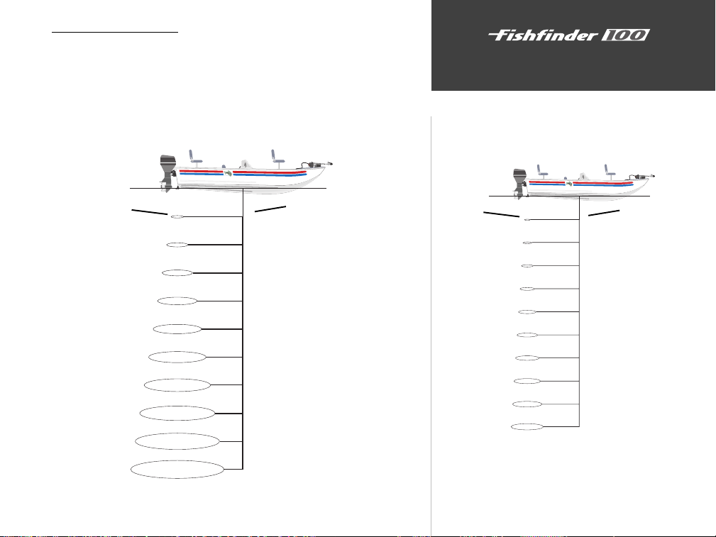
The area covered by the transmitted sound waves is determined by the
cone angle of the transducer and the water depth. Using Garmin’s standard
20° transducer, the coverage is approximately 1/3rd of the water depth. As
shown in Example 1, the coverage area at a 30 foot depth is approximately
a 10 foot diameter circle. The scale below illustrates how coverage
increases as depth increases.
On the Water
Transducer Coverage
Coverage
Diameter
1'
2'
3'
4'
5'
6'
7'
8'
9'
10'
3'
6'
9'
12'
15'
18'
21'
24'
27'
30'
Example 1.
Depth
Coverage
Diameter
Depth
8° Transducer Coverage Chart
29
Page 38
On the Water
Understanding the Chart
Enlarged
Transducer
View
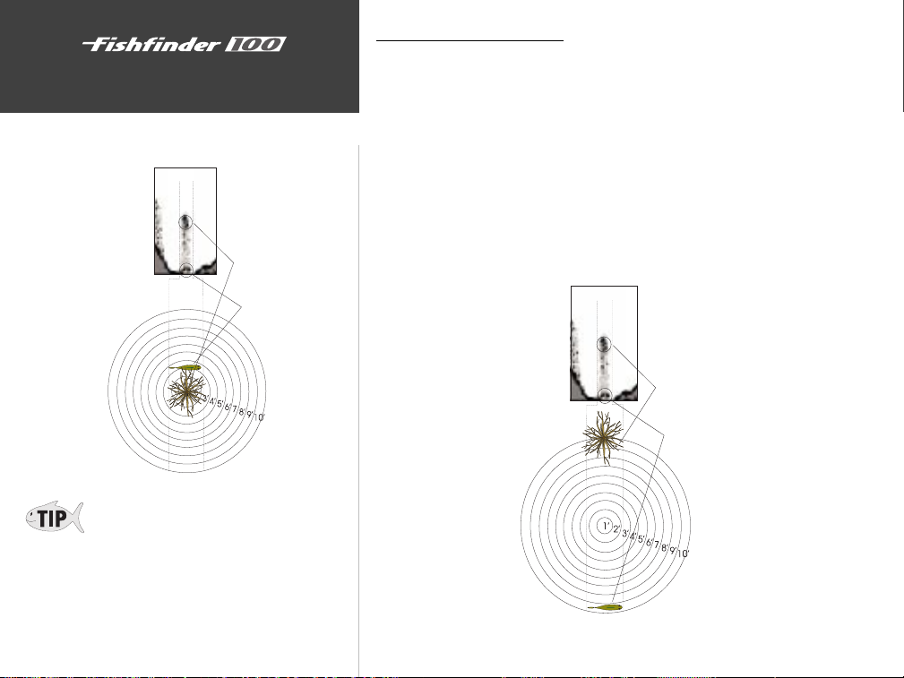
Remember that the Fishfinder displays a 2D
picture of the underwater environment. The
fish and tree could be located anywhere in the
coverage area at that slice of time.
30
Branches
Fish
Understanding the Chart
It is important to understand that the unit does not display a 3-D
representation of the underwater environment. The unit can display
multiple things at the same time, but can not determine where the return
originated only when it was received.
Example 2 provides a look at the underwater world from a top view,
and relates that view to what would be displayed on the chart. On the chart
it appears the fish and tree are side by side, but when we look at the scene
from the top we can see that the fish is several feet from the tree. It is
important to remember that the fishfinder can not determine where in the
coverage area the tree or fish are, only that the returns were received in the
same time frame.
Branches
Enlarged
Transducer
View
Example 2.
Fish
Page 39
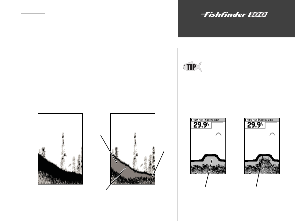
Whiteline
The Fishfinder 100 can help you to determine if the bottom is hard or
soft. When the sonar soundwaves are reflected back by the bottom, a hard
bottom will return a stronger signal than a soft bottom. The stronger
bottom return, the wider the bottom layer is displayed. The unit uses the
whiteline function to make this bottom layer information easier to
distinguish.
When viewing the display without Whiteline active, the bottom return
is black. While you can make some determination of the bottom type, the
black return makes this more difficult. With the whiteline active the
bottom return appears layered in shades of gray and black and makes
determining the bottom type easier and more reliable. Example 3 shows
the bottom return with and without the whiteline activated.
Hard
Bottom
Soft
Bottom
On the Water
Understanding the Chart
Whiteline can also help you to determine the
type of bottom structure that is displayed on
chart. By determining the hardness of the
structure you can make a better informed
decision on the type of structure.
Whiteline Turned Off
Whiteline
Example 3.
Whiteline Active
Structure is hard,
probably a rock or stump
Structure is soft,
probably a mud pile
31
Page 40
On the Water
Understanding the Chart
Thermoclines
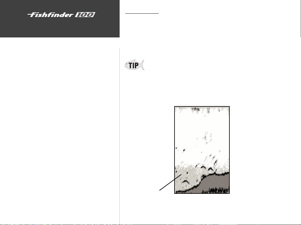
One of the unique features offered by GARMIN is See-Thru™
technology. See-Thru™ technology allows the Fishfinder 100 to see
through thermoclines and helps locate fish where they live, and fish love
the thermocline.
A rough definition of a thermocline is a break in water where the water
temperature changes faster than the water above it. The thermocline
usually displays as a gray level as shown below.
32
Thermocline
Page 41
Simulator Mode
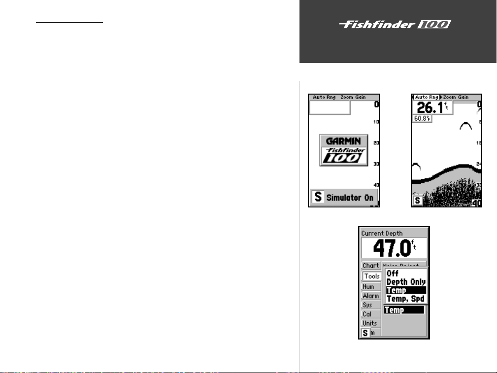
The Fishfinder 100 comes with a built-in simulator mode that will
allow the user to practice and learn the operation of the unit at home rather
than on the water.
To start the simulator mode, turn the unit on without a transducer
installed. As the unit powers on, the unit will indicate that it is running the
simulator mode by displaying a message across the bottom of the chart.
The message will be replaced by the simulator mode icon in the lower left
corner of the chart. While in the simulator mode, the unit will display a
random bottom scene and the Fishfinder 100 can be controlled just as if it
were on the water.
The unit can be configured to act as if a variety of transducers are
installed while in the simulator mode.
To Select a Specific Transducer:
1. Press the Setup button on the face of the unit.
2. Using the arrow keys, highlight the ‘Tools’ tab then the ‘Simulator’
selection field.
3. Press ENTER. Choose the desired transducer from the list.
4. Press ENTER to accept the transducer selection.
To exit the Simulator, turn the unit off.
On the Water
Simulator Mode
Simulator Message and Icon
Simulator Transducer Selections
33
Page 42
Appendix A
On the Water
Specifications
Physical
Case: Fully Gasketed, high-impact plastic alloy
Display: 3.3” x 2” (8.3 x 5 cm) 160 H x 100 W pixels
Size: 4.9” H x 5.3” W x 2.7” D (12.5 x 13.5 x 6.9 cm)
Weight: 13 oz.
Temperature Range: +5° to 158°F (-15C to 70C)
Waterproof: IEC 529, level IPX-7 (submerged to 1 meter for 30 minutes)
Power
Input: 10 to 18 VDC with High Voltage Protect
Usage: 3.5 watts maximum
Nominal: 12 VDC @ 0.28 amps
Performance
Sonar Power Output: 150 watts (RMS), 1200 watts (peak to peak)
Frequency: 200 kHz
Depth 200 foot max depth*
NMEA
Support: NMEA 0183 Versions 2.0 - 2.3
Output Sentences: DBT, DPT, MTW, VHW
* Depth capacity is dependent on water salinity, bottom type and other water conditions.
34
Specifications subject to change without notice.
Page 43
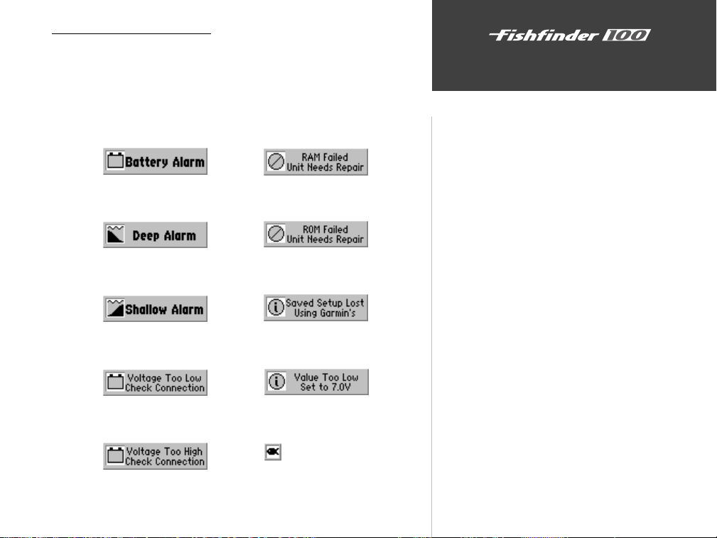
Alarm Messages and Icons
The Fishfinder 100 displays a message when an alarm is tripped. To
clear the message press the ENTER key. If the ENTER key is not pressed,
the unit will automatically remove most messages after 10 seconds and
display a reminder icon in the lower left corner of the chart until the alarm
is no longer valid.
Appendix B
Messages and Alarms
Battery Voltage Low
Deep Water Alarm
Shallow Water Alarm
Supply Voltage Low
Supply Voltage High
Unit Needs Repair
Unit Needs Repair
Memory Deleted
Increase Setting
Fish Alarm
35
Page 44
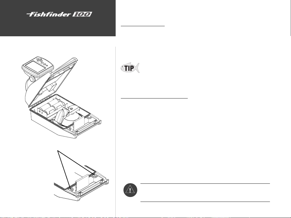
Fishfinder 100 Portable
Appendix C
Fishfinder 100 Portable
Secure Fishfinder 100 to the
boat using the provided eyelets
The Portable Case
The Portable Case is designed for rugged use and provides storage for
the Battery Pack and the Portable Suction Cup Transducer and a mount for
the Fishfinder 100. The case is water resistant but is not designed to float in
the event it should go overboard.
Use the two square eyelets located by the handle to secure the
Fishfinder 100 Portable Case to the boat.
The Suction Cup Transducer
Using the Portable unit you will still need to find a suitable location for
the transducer. If you are in a slow moving boat such as a canoe or flat
bottom boat, the mounting location is not as critical. Follow these simple
guidelines and you should be fine.
1. Look for clean (non-turbulent) water
2. Mount the transducer with approximately 1/2” extending beyond the
bottom of the boat.
3. Do not mount the transducer behind strakes on the bottom of the boat
or in the path of a prop.
4. If you experience poor reception, try another location.
I
WARNING! Speeds in excess or 20 MPH may cause the
transducer to fly off and strike occupants of the boat.
36
Page 45
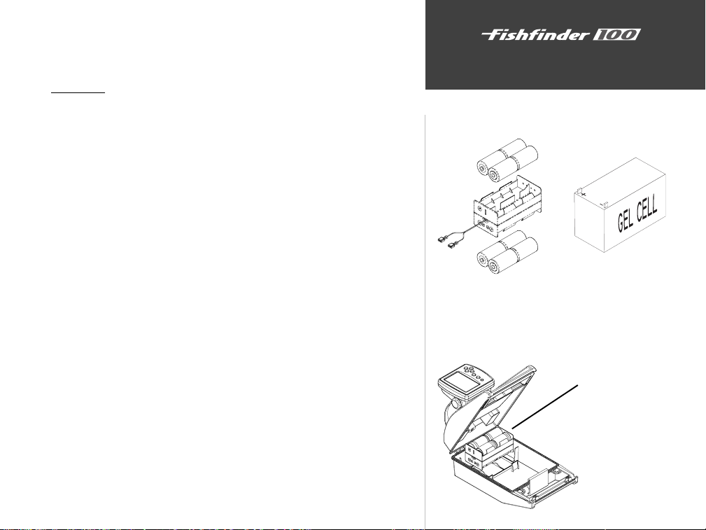
When storing the Suction Cup Transducer in the case, dry the
transducer and cable to avoid corrosion. If using in Salt Water, rinse the
transducer and cable in fresh water and dry before storing in the case.
Batteries
The Fishfinder 100 Portable comes with a D-Cell battery pack. Eight
D-Cell Alkaline batteries will provide approximately 20 hours of continuous operation. You have the option of purchasing a 12 Volt Rechargeable
Gel-Cell Battery for the portable case. If using a Gel-Cell battery you can
anticipate approximately 40 hours of continuous operation between
charges. Cold temperatures reduce battery life.
Installing the D-Cell Batteries:
1. Disconnect the Red and Black leads.
2. Install the batteries noting the correct polarity.
3. Reconnect the Red and Black leads and place the battery pack (batteries
down) in the provide location within the case.
Installing a Gel Cell Battery:
Verify that the Gel-Cell battery has male spade connectors installed on
the positive and negative leads.
1. Disconnect the Red and Black leads and remove the D-Cell Battery Pack.
2. Connect the Red and Black Gel-Cell leads to the Red and Black wires in
the portable case.
3. Place the Gel-Cell battery in the same location as the D-Cell Battery
Pack. The Portable Case was designed to accommodate a 12 Volt GelCell battery and hold it securely in place.
Appendix C
Fishfinder 100 Portable
D-Cell and Optional Gel-Cell Battery Packs
Install the battery pack into
the moulded location in the
Portable case
37
Page 46
38
Appendix D
Index
A
Accessories ...................................................................................................... ii
Adjust the Scroll Speed .................................................................................. 16
Adjustment Bar .............................................................................................. 12
Alarms .................................................................................................... 22, 35
Arrow Keys .................................................................................................... 10
B
Batteries ......................................................................................................... 37
Battery Voltage (alarm).................................................................................... 23
Battery Voltage (display) ................................................................................ 20
Beeper ............................................................................................................ 24
C
Calibration ..................................................................................................... 25
Chart ............................................................................................................. 15
Contrast ......................................................................................................... 24
D
Deep Water .................................................................................................... 23
Depth ............................................................................................................ 26
Display ........................................................................................................... vi
Display Installation .......................................................................................... 7
E
Enter Key ........................................................................................................ 10
F
Factory Setup ................................................................................................ 27
Fish Alarm ...................................................................................................... 22
Fish Symbols ................................................................................................. 15
Fishfinder 100 Portable ................................................................................. 36
Flasher ............................................................................................................ 19
Flush Mount ..................................................................................................... 8
G
Gain ............................................................................................................... 14
Page 47
I
In-hull Installation ........................................................................................... 3
Installing the Display ....................................................................................... 7
K
Keel Offset ...................................................................................................... 25
Keypad .......................................................................................................... 10
L
Limited Warranty .............................................................................................. i
M
Memory .......................................................................................................... 27
Messages ........................................................................................................ 35
N
NMEA Output ............................................................................................... 24
Noise Reject .................................................................................................... 18
Number Size ................................................................................................... 20
Numbers ......................................................................................................... 20
O
Operation ...................................................................................................... 28
P
Portable Case ................................................................................................. 36
Power Key ..................................................................................................... 10
R
Range ............................................................................................................. 12
Remember ...................................................................................................... 27
S
Scale .............................................................................................................. 17
Scroll Speed ................................................................................................... 16
Setup Key ...................................................................................................... 10
Setup Menu ................................................................................................... 15
Shallow Water ................................................................................................ 22
Simulator ....................................................................................................... 19
Appendix D
Index
39
Page 48
Appendix D
Index
S
Software Version ............................................................................................ 27
Specifications ................................................................................................. 34
Speed 2 ...................................................................................................... 1, 26
Suction Cup Transducer ................................................................................. 36
System ............................................................................................................ 24
T
Table of Contents............................................................................................ vi
Temperature ........................................................................................... 21, 26
Testing the Installation ...................................................................................... 9
Tools ............................................................................................................... 18
Transducers ..................................................................................................... 1
Transom Mount Installation ............................................................................. 2
Trolling Motor Installation ............................................................................... 4
U
Understanding Sonar ..................................................................................... 28
Units .............................................................................................................. 26
V
View .............................................................................................................. 13
W
Water Type ..................................................................................................... 25
Whiteline ....................................................................................................... 16
Wiring Harness Installation ........................................................................ 5, 6
Z
Zoom .............................................................................................................. 13
40
Page 49

© 1999 GARMIN Corporation
GARMIN International, Inc.
1200 East 151st Street, Olathe, Kansas 66062, U.S.A.
GARMIN (Europe) Ltd.
Unit 5, The Quadrangle, Abbey Park Industrial Estate, Romsey, SO51 9AQ, U.K.
GARMIN (Asia) Corporation
No. 68, Jangshu 2nd Road, Shijr, Taipei County, Taiwan
www.garmin.com
Part Number 190-00173-00 Rev. A
 Loading...