

Page 1

190-00303-24 January, 2012 Revision A
GDR 66
Transceiver Installation Manual
DRAFT
Page 2

© Copyright 2011
DRAFT
Garmin Ltd. or its subsidiaries
All Rights Reserved
Except as expressly provided herein, no part of this manual may be reproduced, copied,
transmitted, disseminated, downloaded or stored in any storage medium, for any purpose without
the express prior written consent of Garmin. Garmin hereby grants permission to download a
single copy of this manual and of any revision to this manual onto a hard drive or other electronic
storage medium to be viewed and to print one copy of this manual or of any revision hereto,
provided that such electronic or printed copy of this manual or revision must contain the complete
text of this copyright notice and provided further that any unauthorized commercial distribution of
this manual or any revision hereto is strictly prohibited.
Garmin International, Inc.
1200 E. 151st Street
Olathe, KS 66062 USA
Telephone: 913.397.8200
Aviation Panel-Mount Technical Support Line (Toll Free) 1.888.606.5482
www.garmin.com
Garmin (Europe) Ltd.
Liberty House, Bulls Copse Road
Hounsdown Business Park
Southampton, SO40 9RB U.K.
+44/ (0) 870.8501241
Garmin AT, Inc.
2345 Turner Rd., SE
Salem, OR 97302 USA
Telephone: 503.581.8101
RECORD OF REVISIONS
Revision Revision Date Description
A 01/17/2012 Initial Release
Page A GDR 66 Installation Manual
Revision A 190-00303-24
Page 3

INFORMATION SUBJECT TO EXPORT CONTROL LAWS
DRAFT
This document may contain information which is subject to the Export Administration Regulations
("EAR") issued by the United States Department of Commerce (15 CFR, Chapter VII, Subchapter C) and
which may not be exported, released, or disclosed to foreign nationals inside or outside of the United States
without first obtaining an export license. The preceding statement is required to be included on any and all
reproductions in whole or in part of this manual.
WARNING
This product, its packaging, and its components contain chemicals known to the
State of California to cause cancer, birth defects, or reproductive harm. This
Notice is being provided in accordance with California's Proposition 65. If you
have any questions or would like additional information, please refer to our web
site at www.garmin.com/prop65
CURRENT REVISION DESCRIPTION
.
Revision
A All All Initial release
Page
Number(s)
Section
Number
DOCUMENT PAGINATION
Section Page Range
Table of Contents i – vi
Section 1 1-1 – 1-8
Section 2 2-1 – 2-4
Section 3 3-1 – 3-4
Section 4 4-1 – 4-10
Appendix A A-1 – A-3
Appendix B B-1 – B-3
Description of Change
GDR 66 Installation Manual Page i
190-00303-24 Revision A
Page 4

TABLE OF CONTENTS
DRAFT
PARAGRAPH PAGE
Section 1 GENERAL DESCRIPTION............................................................. 1-1
1.1 Introduction ..................................................................................................................... 1-1
1.2 Equipment Description................................................................................................... 1-1
1.3 Interface Summary .........................................................................................................1-1
1.4 Technical Specifications .................................................................................................1-2
1.4.1 Environmental Qualification Form..................................................................................... 1-2
1.4.2 Physical Characteristics ...................................................................................................... 1-2
1.4.3 General Specifications ........................................................................................................ 1-2
1.4.4 Power Requirements ........................................................................................................... 1-3
1.4.5 Transmitter Power Versus Aircraft Bus Voltage................................................................ 1-3
1.4.6 COM Transceiver Specifications........................................................................................ 1-4
1.4.7 Digital Transceiver Characteristics..................................................................................... 1-4
1.4.8 License Requirements......................................................................................................... 1-6
1.5 Certification..................................................................................................................... 1-6
1.5.1 TSO/ETSO Compliance......................................................................................................1-7
1.5.2 TSO/ETSO Deviations........................................................................................................ 1-7
1.6 Reference Documents .....................................................................................................1-7
1.7 Aviation Limited Warranty ............................................................................................. 1-8
Section 2 INSTALLATION OVERVIEW....................................................... 2-1
2.1 Introduction ..................................................................................................................... 2-1
2.2 Installation Materials....................................................................................................... 2-1
2.2.1 Equipment Available .......................................................................................................... 2-1
2.2.2 Additional Equipment Required ......................................................................................... 2-1
2.3 Installation Considerations.............................................................................................. 2-2
2.3.1 Antenna Considerations...................................................................................................... 2-2
2.3.2 Com Antenna Location....................................................................................................... 2-2
2.4 Cabling and Wiring .........................................................................................................2-3
2.5 Cooling Air...................................................................................................................... 2-3
2.6 Mounting Requirements.................................................................................................. 2-4
Section 3 INSTALLATION PROCEDURE .................................................... 3-1
3.1 Unpacking Unit ............................................................................................................... 3-1
3.2 Wiring Harness Installation............................................................................................. 3-1
3.3 Antenna Installation ........................................................................................................3-2
3.4 Cable Installation ............................................................................................................3-3
3.5 Backshell Assembly ........................................................................................................3-4
3.6 Final Installation.............................................................................................................. 3-4
3.7 Post Installation Configuration & Checkout ...................................................................3-4
3.8 Continued Airworthiness ................................................................................................3-4
Page ii GDR 66 Installation Manual
Revision A 190-00303-24
Page 5

TABLE OF CONTENTS
DRAFT
PARAGRAPH PAGE
Section 4 SYSTEM INTERCONNECTS......................................................... 4-1
4.1 Pin Function List .............................................................................................................4-1
4.1.1 P661 (COM)........................................................................................................................ 4-1
4.1.2 P662 (Main) ........................................................................................................................ 4-2
4.2 Power Functions.............................................................................................................. 4-4
4.2.1 Aircraft Power..................................................................................................................... 4-4
4.2.2 Remote Power Off .............................................................................................................. 4-4
4.2.3 GDR System ID Program ................................................................................................... 4-4
4.3 Serial Data....................................................................................................................... 4-5
4.3.1 RS-422 ................................................................................................................................ 4-5
4.3.2 RS-232 ................................................................................................................................ 4-5
4.3.3 ARINC 429 ......................................................................................................................... 4-6
4.4 Discrete I/O ..................................................................................................................... 4-7
4.4.1 Active Low Discrete Inputs ................................................................................................ 4-7
4.4.2 Key Event Out..................................................................................................................... 4-7
4.5 Audio............................................................................................................................... 4-8
4.5.1 Analog Audio...................................................................................................................... 4-8
4.5.2 ACARS/SELCAL............................................................................................................... 4-9
Appendix A Outline and Installation Drawings............................................. A-1
Appendix B Interconnect Examples.................................................................B-1
GDR 66 Installation Manual Page iii
190-00303-24 Revision A
Page 6

LIST OF FIGURES
DRAFT
FIGURE PAGE
Section 1 GENERAL DESCRIPTION............................................................. 1-1
Section 2 INSTALLATION OVERVIEW....................................................... 2-1
Figure 2-1: GDR 66 Standalone Rack ..................................................................................2-4
Section 3 INSTALLATION PROCEDURE .................................................... 3-1
Figure 3-1 TNC Connector Installation ................................................................................3-3
Section 4 SYSTEM INTERCONNECTS......................................................... 4-1
Figure 4-1 View of J661 connector, from back of unit......................................................... 4-1
Figure 4-2 View of J662 connector, from back of unit......................................................... 4-2
Appendix A Outline and Installation Drawings ............................................ A-1
Figure A-1 GDR 66 Outline Drawing.................................................................................. A-1
Figure A-2 GDR 66 Connector/Rack Assembly Drawing.................................................. A-2
Figure A-3 GDR 66 Minimum Installation/Removal Clearance ......................................... A-3
Appendix B Interconnect Examples ................................................................B-1
Figure B-1 GDR 66 Power and Antenna Interconnect Example ......................................... B-1
Figure B-2 GDR 66 VDL Mode 2 Interconnect Example ................................................... B-2
Figure B-3 GDR 66 Analog Voice Mode Interconnect Example ........................................ B-3
Page iv GDR 66 Installation Manual
Revision A 190-00303-24
Page 7

LIST OF TABLES
DRAFT
TABLE PAGE
Section 1 GENERAL DESCRIPTION .............................................................1-1
Table 1-1 Physical Characteristics........................................................................................ 1-2
Table 1-2 General Specifications.......................................................................................... 1-2
Table 1-3 Power Requirements............................................................................................. 1-3
Table 1-4 TX Power (into 50Ω load) vs Bus Voltage .......................................................... 1-3
Table 1-5 Transceiver Specifications ................................................................................... 1-4
Table 1-6 Digital Transceiver Characteristics ...................................................................... 1-4
Table 1-7 License Requirements .......................................................................................... 1-6
Table 1-8 TSO/ETSO Compliance ....................................................................................... 1-7
Table 1-9 TSO/ETSO Deviations ......................................................................................... 1-7
Table 1-10 Reference Documents......................................................................................... 1-7
Section 2 INSTALLATION OVERVIEW........................................................2-1
Table 2-1 Available Units..................................................................................................... 2-1
Table 2-2 Equipment Available............................................................................................ 2-1
Table 2-3 Additional Equipment Required........................................................................... 2-1
Section 3 INSTALLATION PROCEDURE.....................................................3-1
Table 3-1: Pin Contact Part Numbers ................................................................................... 3-1
Table 3-2 Recommended Crimp Tools................................................................................. 3-2
Section 4 SYSTEM INTERCONNECTS..........................................................4-1
Table 4-1 P661 Connector .................................................................................................... 4-1
Table 4-2 P662 Connector .................................................................................................... 4-2
Table 4-3 Aircraft Power ...................................................................................................... 4-4
Table 4-4 Remote Power Off................................................................................................ 4-4
Table 4-5 System ID Program .............................................................................................. 4-4
Table 4-6 Unit Number Configuration ................................................................................. 4-5
Table 4-7 RS-422.................................................................................................................. 4-5
Table 4-8 RS-232.................................................................................................................. 4-5
Table 4-9 ARINC 429........................................................................................................... 4-6
Table 4-10 Discrete Inputs.................................................................................................... 4-7
Table 4-11 Key Event Out .................................................................................................... 4-7
Table 4-12 Com Mic Audio.................................................................................................. 4-8
Table 4-13 Com Audio Out .................................................................................................. 4-8
Table 4-14 Com Mic Key ..................................................................................................... 4-8
Table 4-15 Com Remote Transfer ........................................................................................ 4-9
Table 4-16 SELCAL Audio and ACARS Data Out ............................................................. 4-9
GDR 66 Installation Manual Page v
190-00303-24 Revision A
Page 8

Page vi GDR 66 Installation Manual
DRAFT
Revision A 190-00303-24
Page 9

1 GENERAL DESCRIPTION
DRAFT
1.1 Introduction
This manual presents mechanical and electrical installation requirements for installing the GDR 66 as part
of a Garmin Integrated Flight Deck. The GDR 66 can be integrated into a variety of airframes under an
appropriate TC or STC. Each airframe installation may vary. Use only approved (type or supplemental
type) data for specific installation instructions in a particular aircraft.
1.2 Equipment Description
The GDR 66 is a remote mounted digital communications transceiver. The GDR 66 operates in the
following modes in the 118.000 to 137.000 MHz VHF aviation communications band:
• Analog Voice Mode (ARINC 716 Voice): Voice communications using DSB-AM modulation with
8.33 and 25 kHz channel spacing.
• VDL Mode 0/A (ARINC 716 Data): ACARS using DSB-AM modulation with a 2.4 kbps data rate
and 25 kHz channel spacing.
• VDL Mode 2 (ARINC 750 Data): Data link using D8PSK modulation with a 31.5 kbps data rate
and 25 kHz channel spacing.
1.3 Interface Summary
The GDR 66 provides the following interfaces:
• 2 RS-422 inputs
• 2 RS-422 outputs
• 1 RS-232 input
• 1 RS-232 output
• 5 configurable ARINC 429 inputs
• 2 configurable ARINC 429 outputs
• 8 configurable active low discrete inputs
• 5 active low discrete inputs: COM MIC KEY*, COM REMOTE TRANSFER*, GDR SYSTEM ID
PROGRAM* 1, GDR SYSTEM ID PROGRAM* 2, GDR SYSTEM ID PROGRAM* 3
• 1 active high discrete input: COM REMOTE POWER OFF
• 1 active low discrete outputs: KEY EVENT OUT*
• 1 analog microphone audio input
• 1 analog audio output
• 1 SELCAL audio/ACARS analog data output
• 2 aircraft power bus inputs
GDR 66 Installation Manual Page 1-1
190-00303-24 Revision A
Page 10

1.4 Technical Specifications
DRAFT
1.4.1 Environmental Qualification Form
It is the responsibility of the installing agency to obtain the latest revision of the GDR 66 Environmental
Qualification Form. This form is available directly from Garmin under the following part number:
GDR 66 Environmental Qualification Form, Garmin part number 005-00548-01
To obtain a copy of this form, see the dealer/OEM portion of the Garmin web site (www.garmin.com)
1.4.2 Physical Characteristics
Table 1-1 list the physical characteristics for the GDR 66 unit, rack, and connectors. Please refer to
Appendix A for additional information.
Table 1-1 Physical Characteristics
Characteristics Specifications
Width (w/out Rack) 2.06 inches (5.23 cm)
Height (w/out Rack) 6.46 inches (16.4 cm)
Depth (w/out Rack) 8.78 inches (22.3 cm)
Width (with Rack) 2.06 inches (5.23 cm)
Height (with Rack) 6.62 inches (16.8 cm)
Depth (with Rack & Connectors) 10.1 inches (25.8 cm)
Unit Weight 4.2 lbs. (1.9 kg)
Rack Weight 0.36 lbs. (0.16 kg)
Connector Weight 0.33 lbs. (0.15 kg)
1.4.3 General Specifications
For detailed specifications, see the Environmental Qualification Form.
Table 1-2 General Specifications
Characteristics Specifications
Operating Temperature Range -55°C to +70°C. For more details see Environmental Qualification Form.
Humidity 95% non-condensing
Altitude Range -1,500 ft to 55,000 ft
Software Compliance RTCA/DO-178B Level C, EUROCAE/ED-12B Level C
Environmental Conditions RTCA/DO-160E, EUROCAE/ED-14E
.
Page 1-2 GDR 66 Installation Manual
Revision A 190-00303-24
Page 11

1.4.4 Power Requirements
DRAFT
Table 1-3 Power Requirements
Characteristics Specifications
Input Voltage
14V
28V
1.4.5 Transmitter Power Versus Aircraft Bus Voltage
14/28 Vdc. See the Environmental Qualification Form for details on surge ratings
and minimum/maximum operating voltages.
Receive (AM or VDL) Maximum 3.0A
Transmit (AM or VDL) Maximum 9.0A
Receive (AM or VDL) Maximum 1.5A
Transmit (AM or VDL) Maximum 8.0A
Table 1-4 TX Power (into 50Ω load) vs Bus Voltage
Aircraft Power Bus Voltage
(V)
V ≥ 22.0 V
22.0 > V ≥11.0
11.0 > V ≥10.25
GDR 66 does not claim Emergency Operation as defined by RTCA DO-160E,
Section 16
Tx Power AM Mode Tx Power VDL Mode
16 W minimum
20 W Typical
8 W minimum
10 W Typical
4 W minimum
5 W Typical
NOTE
15 W minimum
20 W Typical
7.5 W minimum
10 W Typical
4 W minimum
5 W Typical
GDR 66 Installation Manual Page 1-3
190-00303-24 Revision A
Page 12

1.4.6 COM Transceiver Specifications
DRAFT
The GDR 66 Transceiver minimally meets the requirements of DO-186B and ED-23B. Refer to Table 1-5
for detailed specifications.
Table 1-5 Transceiver Specifications
Characteristics Specifications
Audio Outputs
Audio Response
Audio Distortion
Receiver Dynamic Range -107 dBm to +10 dBm typical
Sensitivity
Squelch
Spurious Response
Multi-Carrier Operation
Transmitter Power See Section 1.4.5
Transmitter Duty Cycle 10% maximum, thermally limited, 30 second limit per transmission
Modulation Capability
Carrier Noise Level Shall be at least 45 dB (S+N)/N
Frequency Stability + / - 5ppm (-55ºC to +70ºC with a 5-minute warmup at -55ºC)
Demodulated Audio Distortion Less than 10% distortion when the transmitter is modulated at least 70%
Sidetone 1.4 Vrms into a 600Ω load
Transmit Modulation Fidelity
Microphone Sensitivity See Section 4.5.1.1
Spurious Emissions - Global
Navigation Satellite System Band
Received Audio: 40 mW minimum into a 600Ω load
SELCAL/Data: 10.4 mW minimum into a 600Ω load
Less than 6 dB of variation between 300 and 2500 Hz
Greater than 40dB rejection above 3750 Hz
Not greater than 20.0% across the band from 300 Hz to 2500 Hz with a
90% modulated signal. No greater than 7.5% with a 30% modulated
signal
(S+N)/N on all channels shall be greater than 6 dB when the RF level
is -107dBm modulated 30% at 1000 Hz
Selectable between 0 to 20 dB SNR. Squelch hysteresis is selectable up
to 15 dB
74 dB minimum (-33 dBm signal produces no more output than desired
signal producing 6 dB (S+N)/N)
Meets multi-carrier sensitivity, distortion, and audio output level
requirements of ED-23C for Class C and Class H2 reveivers.
The modulation shall not be less than 70% with a standard modulator
signal applied to the transmitter
Shall be less than 6 dB when the audio input frequency is varied from 350
to 2500 Hz
Harmonic Emission products in the band extending from 1559 to 1610
Mhz shall be no greater than -60dBm
1.4.7 Digital Transceiver Characteristics
The GDR 66 Transceiver minimally meets the requirements of DO-281A. Refer to Table 1-6 for detailed
specifications.
Table 1-6 Digital Transceiver Characteristics
Characteristics Specifications
Dynamic Range +10dBm to -98dBm typical
Sensitivity Uncorrected BER of no more than 0.001 at -98 dBm
Transmitter Power See Section 1.4.5
Transmitter Duty Cycle 20% maximum, thermally limited
Modulation Capability D8PSK
Frequency Stability + / - 5ppm (-55ºC to +70ºC with a 5-minute warmup at -55ºC)
Transmit Symbol Constellation Error EVM of less than 6%
Spurious Emissions - Global
Navigation Satellite System Band
Page 1-4 GDR 66 Installation Manual
Revision A 190-00303-24
Harmonic Emission products in the band extending from 1559 to 1610
Mhz shall be no greater than -60dBm
Page 13

1.4.8 License Requirements
DRAFT
The Telecommunications Act of 1996, effective February 8, 1996, provides the FCC discretion to
eliminate radio station license requirements for aircraft and ships. The GDR 66 installation must comply
with current transmitter licensing requirements. To find out the specific details on whether a particular
installation is exempt from licensing, please visit the FCC web site http://wireless.fcc.gov/aviation
Table 1-7 License Requirements
Characteristic Specification
Transmitter Description: Aviation-band VHF transceiver with 25 and 8.33 kHz channel spacing.
Antenna Characteristics: Broad band, 50 ohm, vertically polarized.
Rated Power: 20 Watts
Emission Type (Voice):
Emission Type (Data):
Frequency of Operation:
If an aircraft license is required, make application for a license on FCC form 404, Application for Aircraft
Radio Station License. The FCC also has a fax-on-demand service to provide forms by fax. The GDR 66
owner accepts all responsibility for obtaining the proper licensing before using the transmitter.
International transmitter license procedures vary by country. Contact the local spectrum agency for license
requirements.
6K00A3E (25 kHz Channel Spacing Mode)
5K60A3E (8.33 kHz Channel Spacing Mode)
13K0A2D (VDL Mode A, ACARS)
14K0G1D (VDL Mode 2)
118.000 – 136.975 MHz in 25 KHz AM or VDL Mode
118.000 – 136.99166 MHz in 8.3 KHz AM Mode
.
NOTE
The VHF transmitter in this equipment is guaranteed to meet federal
communications commission acceptance over the operating temperature range.
Modifications not expressly approved by Garmin could invalidate the license and
make it unlawful to operate the equipment.
1.5 Certification
The conditions and tests required for TSO approval of this article are minimum performance standards. It
is the responsibility of those installing this article either on or within a specific type or class of aircraft to
determine that the aircraft installation conditions are within the TSO standards. TSO articles must have
separate approval for installation in an aircraft. The article may be installed only if performed under 14
CFR part 43 or the applicable airworthiness requirements. At the time of publication, installations of this
TSO approved article are only approved when installed in an aircraft as part of a Garmin Integrated Flight
Deck under an appropriate TC or STC.
The Appliance Project Identifier (API) for the GDR 66 is GMN-00832. Documents submitted to the FAA,
EASA and other regulatory agencies on behalf of this project will be filed under and referred to by this
number.
GDR 66 Installation Manual Page 1-5
190-00303-24 Revision A
Page 14

1.5.1 TSO/ETSO Compliance
DRAFT
Table 1-8 TSO/ETSO Compliance
Function
VHF COM Transceiver from
117.975 – 137.000 MHz
VDL Mode 2 Communications
Equipment
Equipment that prevents blocked
channels due to unintentional
transmissions
1.5.2 TSO/ETSO Deviations
TSO/ETSO Deviation
1. Garmin was granted a deviation from TSO-C169a paragraph 4.a.2 to allow the unit to be permanently and legibly marked with a serial number and not the date of manufacture. The justification
for this deviation is per FAA Memorandum “FAA Order 8150.1B, Technical Standard Order Pro-
TSO-C169a
ETSO-2C37e
ETSO-2C38e
ETSO-2C128
gram, Policy Clarification” which states that the date of manufacture must be used in lieu of the
optional serial number when that information is critical for maintenance and/or inspections. An
equivalent level of safety is provided since the date of manufacture is not critical for maintenance
and/or inspections of this appliance. The appliance will be marked with a serial number.
1. Garmin was granted a deviation from ETSO-2C37e to use DO-160E instead of DO-160D.
Equivalent Level of Safety (ELOS) is provided by use of a later revision requirement document.
2. Garmin was granted a deviation from ETSO-2C37e to use ED-23B amendment 3 in addition to
ED-23B. ELOS is provided by use of a later revision requirement document.
1. Garmin was granted a deviation from ETSO-2C38e to use DO-160E instead of DO-160D.
ELOS is provided by use of a later revision requirement document.
2. Garmin was granted a deviation from ETSO-2C38e to use ED-23B amendment 3 in addition to
ED23B. ELOS is provided by use of a later revision requirement document.
1. Garmin was granted a deviation from ETSO-2C128 to use DO-160E instead of DO-160D.
ELOS is provided by use of a later revision requirement document.
TSO/ETSO/
RTCA/EUROCAE
TSO-C169a
ETSO-2C37e
ETSO-2C38e
RTCA/DO-186B
EUROCAE/ED-23B
TSO-C160
RTCA/DO-281A
EUROCAE/ED-92A
TSO-C128A
ETSO-2C128
RTCA/DO-207
EUROCAE/ED-67
Table 1-9 TSO/ETSO Deviations
Category
TX – 3,4,5,6
RX – C,E
TX – 7,8
RX – F
Architecture – Y
N/A
Applicable LRU SW
Part Numbers
006-B1055-(_)
006-B1056-(_)
006-B1055-(_)
006-B1056-(_)
006-B1055-(_)
006-B1056-(_)
1.6 Reference Documents
The following publications are sources of additional information for installing the GDR 66. Before
installing the GDR 66, the technician should read all referenced materials along with this manual.
Table 1-10 Reference Documents
Part Number Document
190-00303-00 G1000 System Installation Manual
190-00303-04 G1000 Line Maintenance and Configuration Manual
190-00313-11 Jackscrew Backshell Installation Instructions
190-00313-50 Garmin Integrated Avionics System Thermal Management Plan
190-00313-51 Garmin Integrated Avionics System Thermal Validation Procedure
Page 1-6 GDR 66 Installation Manual
Revision A 190-00303-24
Page 15

1.7 Aviation Limited Warranty
DRAFT
All Garmin avionics products are warranted to be free from defects in materials or workmanship for: one
years from the date of purchase for new Remote-Mount and Panel-Mount products; one year from the date
of purchase for new portable products and any purchased newly-overhauled products; six months for
newly-overhauled products exchanged through a Garmin Authorized Service Center; and 90 days for
factory repaired or newly-overhauled products exchanged at Garmin in lieu of repair. Within the applicable
period, Garmin will, at its sole option, repair or replace any components that fail in normal use. Such
repairs or replacement will be made at no charge to the customer for parts or labor, provided that the
customer shall be responsible for any transportation cost. This warranty does not apply to: (i) cosmetic
damage, such as scratches, nicks and dents; (ii) consumable parts, such as batteries, unless product damage
has occurred due to a defect in materials or workmanship; (iii) damage caused by accident, abuse, misuse,
water, flood, fire, or other acts of nature or external causes; (iv) damage caused by service performed by
anyone who is not an authorized service provider of Garmin; or (v) damage to a product that has been
modified or altered without the written permission of Garmin. In addition, Garmin reserves the right to
refuse warranty claims against products or services that are obtained and/or used in contravention of the
laws of any country.
THE WARRANTIES AND REMEDIES CONTAINED HEREIN ARE EXCLUSIVE AND IN LIEU OF
ALL OTHER WARRANTIES, WHETHER EXPRESS, IMPLIED OR STATUTORY, INCLUDING ANY
LIABILITY ARISING UNDER ANY WARRANTY OF MERCHANTABILITY OR FITNESS FOR A
PARTICULAR PURPOSE, STATUTORY OR OTHERWISE. THIS WARRANTY GIVES YOU
SPECIFIC LEGAL RIGHTS, WHICH MAY VARY FROM STATE TO STATE.
IN NO EVENT SHALL GARMIN BE LIABLE FOR ANY INCIDENTAL, SPECIAL, INDIRECT OR
CONSEQUENTIAL DAMAGES, WHETHER RESULTING FROM THE USE, MISUSE OR
INABILITY TO USE THE PRODUCT OR FROM DEFECTS IN THE PRODUCT. SOME STATES DO
NOT ALLOW THE EXCLUSION OF INCIDENTAL OR CONSEQUENTIAL DAMAGES, SO THE
ABOVE LIMITATIONS MAY NOT APPLY TO YOU.
Garmin retains the exclusive right to repair or replace (with a new or newly-overhauled replacement
product) the product or software or offer a full refund of the purchase price at its sole discretion. SUCH
REMEDY SHALL BE YOUR SOLE AND EXCLUSIVE REMEDY FOR ANY BREACH OF
WARRANTY.
Online Auction Purchases: Products purchased through online auctions are not eligible for warranty
coverage. Online auction confirmations are not accepted for warranty verification. To obtain warranty
service, an original or copy of the sales receipt from the original retailer is required. Garmin will not
replace missing components from any package purchased through an online auction.
International Purchases: A separate warranty may be provided by international distributors for devices
purchased outside the United States depending on the country. If applicable, this warranty is provided by
the local in-country distributor and this distributor provides local service for your device. Distributor
warranties are only valid in the area of intended distribution. Devices purchased in the United States or
Canada must be returned to the Garmin service center in the United Kingdom, the United States, Canada,
or Taiwan for service.
Garmin International, Inc. Garmin (Europe) Ltd.
1200 East 151st Street Liberty House, Bulls Copse Road
Olathe, Kansas 66062, U.S.A. Hounsdown Business Park
Phone:913/397.8200 Romsey, SO40 9RB, U.K.
FAX:913/397.0836 Phone:44/ (0) 870.8501241
FAX:44/ (0) 870.850125
GDR 66 Installation Manual Page 1-7
190-00303-24 Revision A
Page 16

This page intentionally left blank
DRAFT
Page 1-8 GDR 66 Installation Manual
Revision A 190-00303-24
Page 17

2 INSTALLATION OVERVIEW
DRAFT
2.1 Introduction
This section provides hardware equipment information for installing the GDR 66, related hardware, and
antennas. Installation of the GDR 66 must follow the aircraft TC or STC requirements. Cabling is
fabricated by the installing agency to fit each particular aircraft. The guidance of FAA advisory circulars
AC 43.13-1B and AC 43.13-2B, where applicable, may be found useful for making retro-fit installations
that comply with FAA regulations.
Refer to Appendix A for rack drawings and dimensions.
2.2 Installation Materials
The GDR 66 is only available as a single unit under the following part number:
Table 2-1 Available Units
Item Garmin P/N
GDR 66 Unit Only, (011-02303-00) 010-00832-00
2.2.1 Equipment Available
Each of the following accessories are provided separately from the GDR 66 and are required for
installation.
Table 2-2 Equipment Available
Item Garmin P/N
GDR 66 Standalone Install Rack 011-02477-00
GDR 66 Connector Kit 011-02304-00
2.2.2 Additional Equipment Required
The following installation accessories are required but not provided:
Table 2-3 Additional Equipment Required
Characteristic Specification
COM Antenna
Headphones* 500 Ω nominal impedance
Microphone* Low impedance, carbon or dynamic, with transistorized pre-amp
Hardware** #10 pan head or hex head fastener (qty 4)
* Only required for voice mode
** Used for mounting unit rack to airframe
Shall meet TSO-C37(), C38(), and C-169(). Broad band, 50 Ω, vertically polarized
with coaxial cable
GDR 66 Installation Manual Page 2-1
190-00303-24 Revision A
Page 18

2.3 Installation Considerations
DRAFT
Fabrication of a wiring harness is required. Sound mechanical and electrical methods and practices are
required for installation of the GDR 66.
2.3.1 Antenna Considerations
Antenna installations on pressurized cabin aircraft require FAA approved installation design and
engineering substantiation data whenever such antenna installations incorporate alteration (penetration) of
the cabin pressure vessel by connector holes and/or mounting arrangements. For needed engineering
support pertaining to the design and approval of such pressurized aircraft antenna installations, it is
recommended that the installer proceed according to any of the following listed alternatives:
1. Obtain approved antenna installation design data from the aircraft manufacturer.
2. Obtain an FAA approved STC, pertaining to, and valid for the antenna installation.
3. Contact the FAA Aircraft Certification Office in the appropriate Region and request identification
of FAA Designated Engineering Representatives (DERs) who are authorized to prepare and
approve the required antenna installation engineering data.
4. Obtain FAA Advisory Circular AC-183C and select (and contact) a DER from the roster of
individuals listed in it.
5. Contact an aviation industry organization such as the Aircraft Electronics Association for
assistance.
2.3.2 Com Antenna Location
The GDR 66 COM antenna should be well removed from all projections, engines and propellers. The
ground plane surface directly below the antenna should be a flat plane over as large an area as possible (18
inches square, minimum). The antenna should be mounted a minimum of three feet from any DME
antennas, three feet from any GPS antennas, and as far as practical from the ELT antenna. Some ELTs
have exhibited re-radiation problems generating harmonics which may interfere with other signals.
In addition, the COM antenna must have at least 16 dB of isolation from other COM antennas to prevent
damage to the GDR 66 COM receiver. For COM antennas mounted on the same side of the fuselage, 16
dB of isolation can be achieved by a physical separation of approximately 3 feet (0.9 meters).
If simultaneous use of two or more COM transceivers is desired the COM antennas must be spaced for
maximum isolation. For a two COM installation, one COM antenna should be mounted on the top of the
fuselage and the other antenna should be mounted on the bottom of the fuselage. For installations with
three COM’s, one COM antenna should be mounted on the top of the fuselage and the other two antennas
should be mounted on the bottom of the fuselage and physically separated from each other as much as
possible.
The recommended minimum isolation between COM antennas for simultaneous use of two or more
COM’s is 40 dB. Separating the COM antennas between the top and bottom of the fuselage typically
provides 35 – 45 dB of isolation for metal skin aircraft. For COM antennas mounted on the same side of
the fuselage, 40 dB of isolation can be achieved by a physical separation of approximately 60 feet (18.3
meters). Receiver sensitivity could be significantly reduced during the transmission of a co-located COM
for installations with less than 40 dB of isolation between the COM antennas. For installations with less
than 23 dB of isolation between COM antennas, cross modulation (bleed-through) could also be
experienced during the transmission of a co-located COM. For COM antennas mounted on the same side
of the fuselage, 23 dB of isolation can be achieved by a physical separation of approximately 9 feet (2.7
meters).
Simultaneous COM performance varies significantly across installations and is affected by both the
isolation between the COM antennas and the separation of the tuned frequencies. Each installation should
be individually examined to determine the expected performance of simultaneous COM.
Page 2-2 GDR 66 Installation Manual
Revision A 190-00303-24
Page 19

2.4 Cabling and Wiring
DRAFT
Refer to the interconnect examples in Appendix B for wire gauge guidance.
The power connection can be run with three AWG #18 wires back to the breaker or can be spliced near the
unit to one AWG #16 or larger wire. Special thin-wall heat shrink tubing is also provided to insulate the
extended barrels inside the backshell. If using AWG #18 barrel contacts, ensure that no two contacts are
mounted directly adjacent to each other. This minimizes the risk of contacts touching and shorting to
adjacent pins and to ground.
Ensure that routing of the wiring does not come in contact with sources of heat, RF or EMI interference.
Check that there is ample space for the cabling and mating connectors. Avoid sharp bends in cabling and
routing near aircraft control cables.
Coaxial cable with 50Ω nominal impedance and meeting applicable aviation regulations should be used for
the installation.
NOTE
RTCA DO-224A assumes 3dB of cable loss in its VDL Typical Uplink Power
Budget. Losses greater than 3dB can reduce transceiver range.
Cabling for the GDR 66 should not be routed near components or cabling which are sources of electrical
noise. Route the GPS, VOR/LOC, and Glideslope antenna cables as far as possible away from all COM
transceivers and antenna cables.
2.5 Cooling Air
Dedicated cooling is not required for the GDR 66 to meet indicated EQF categories. Thermal analysis
must be performed to verify that high temperature limits implied by the indicated EQF categories for the
GDR 66 are not exceeded during normal operation of the aircraft. Guidance can be found in the Garmin
Integrated Avionics System Thermal Management Plan document (GPN 190-00313-50) and the Garmin
Integrated Avionics System Thermal Validation Procedure (GPN 190-00313-51).
Contact Garmin for additional cooling guidance.
GDR 66 Installation Manual Page 2-3
190-00303-24 Revision A
Page 20
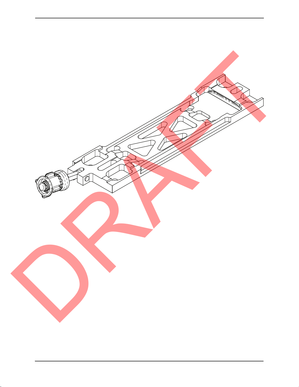
2.6 Mounting Requirements
DRAFT
The GDR 66 mounting surface should be capable of providing a sufficient electrical bond to the aircraft to
minimize radiated EMI and provide protection from High-Intensity Radiation Fields (HIRF). Bonding
resistance measured between the GDR 66 standalone install rack and the airframe should be less than 2.5
mlliOhms. The GDR 66 must be mounted in the vertical position using the GDR 66 standalone rack.
Approximately one inch of clearance should be provided on the left side of the GDR 66 to allow for
cooling of the heat sink. Refer to Appendix A for outline and installation drawings.
Figure 2-1: GDR 66 Standalone Rack
Page 2-4 GDR 66 Installation Manual
Revision A 190-00303-24
Page 21

3 INSTALLATION PROCEDURE
DRAFT
3.1 Unpacking Unit
Carefully unpack the equipment and make a visual inspection of the unit for evidence of damage incurred
during shipment. If the unit is damaged, notify the carrier and file a claim. To justify a claim, save the
original shipping container and all packing materials. Do not return the unit to Garmin until the carrier has
authorized the claim.
Retain the original shipping containers for storage. If the original containers are not available, a separate
cardboard container should be prepared that is large enough to accommodate sufficient packing material to
prevent movement.
3.2 Wiring Harness Installation
Allow adequate space for installation of cables and connectors. The installer shall supply and fabricate all
of the cables. All electrical connections are made through 44 and 62-pin D-subminiature connectors.
Section 4 defines the electrical characteristics of all input and output signals. Required connectors and
associated hardware are supplied with the connector kit.
See Appendix B for examples of interconnect wiring diagrams. Construct the actual harnesses in
accordance with aircraft manufacturer authorized interconnect standards.
Contacts for the 62 and 44 pin connectors must be crimped onto the individual wires of the aircraft wiring
harness. Tables 3-1 and 3-2 list contact part numbers (for reference) and recommended crimp tools.
Table 3-1: Pin Contact Part Numbers
Manufacturer 62 pin connector (P662), 44 pin connector (P661)
18-20 AWG
(Power Only)
Garmin P/N 336-00044-00 336-00021-00
Military P/N N/A M39029/58-360
AMP N/A 204370-2
Positronic N/A MC8522D
ITT Cannon N/A 030-2042-000
22-28 AWG
GDR 66 Installation Manual Page 3-1
190-00303-24 Revision A
Page 22
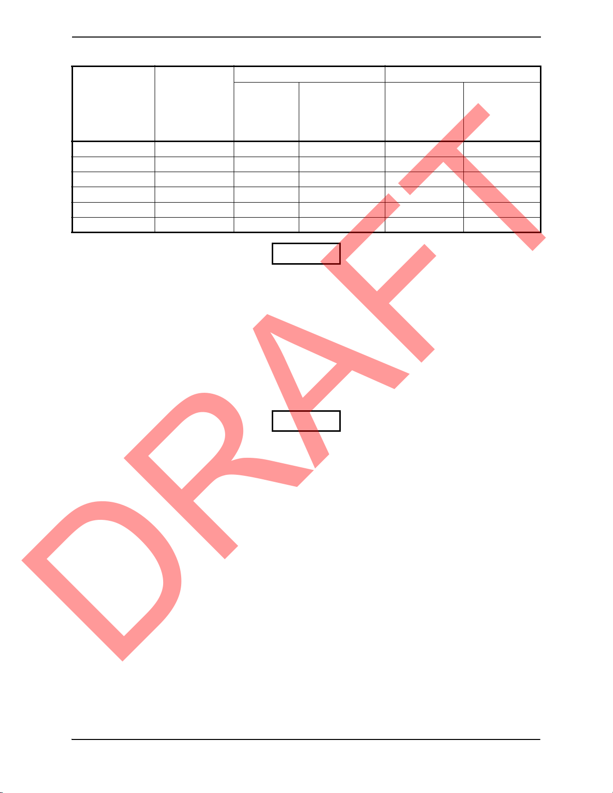
Table 3-2 Recommended Crimp Tools
DRAFT
Manufacturer Hand
Crimping
Tool
Military P/N M22520/2-01 N/A M81969/1-04 M22520/2-09 M81969/1-04
Positronic 9507 9502-11 M81969/1-04 9502-4 M81969/1-04
ITT Cannon 995-0001-584 N/A N/A M22520/2-09 274-7048-000
AMP 601966-1 N/A 91067-1 601966-6 91067-1
Daniels AFM8 K774 M81969/1-04 K42 M81969/1-04
Astro 615717 N/A M81969/1-04 615725 M81969/1-04
1. Non-Garmin part numbers shown are not maintained by Garmin and consequently are subject to
change without notice.
2. Extracting the #18 or #20 contact requires that the expanded wire barrel be cut off from the
contact. It may also be necessary to push the pin out from the face of the connector when using
an extractor due to the absence of the wire. A new contact must be used when reassembling the
connector.
Positioner Insertion/
18-20 AWG 22-28 AWG
Positioner Insertion/
Extraction
Tool
(note 2)
NOTE
Extraction
Tool
3.3 Antenna Installation
Follow the manufacturers’ instructions for installation of the COM antenna.
CAUTION
Do not use construction grade RTV sealant or sealants containing acetic acid.
These sealants may damage the electrical connections to the antenna. Use of
these type sealants may void the antenna warranty.
Page 3-2 GDR 66 Installation Manual
Revision A 190-00303-24
Page 23
3.4 Cable Installation
DRAFT
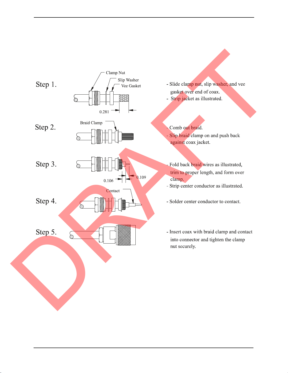
1. Route the coaxial cable to the rack location keeping in mind the recommendations of Section 2.
Secure the cable in accordance with good aviation practice.
2. Trim the coaxial cable to the desired length and install the TNC connector per the cabling
instructions on Figure 3-1. If the connector is provided by the installer, follow the connector
manufacturer’s instructions for cable preparation
.
Figure 3-1 TNC Connector Installation
GDR 66 Installation Manual Page 3-3
190-00303-24 Revision A
Page 24

3.5 Backshell Assembly
DRAFT
The GDR 66 connector kit includes two Garmin backshell assemblies. Garmin’s backshell gives the
installer the ability to easily terminate shield grounds at the backshell housing. Refer to the Jackscrew
Backshell Installation Instructions (Garmin part number 190-00313-11) for backshell assembly
instructions.
3.6 Final Installation
For final installation and assembly, refer to the outline and installation drawings shown in Appendix A of
this manual.
3.7 Post Installation Configuration & Checkout
The GDR 66 must be installed as part of a Garmin Integrated Flight Deck and have FAA approved
configuration data. Configuration data is loaded to the GDR 66 from an aircraft-specific Garmin SW
Loader Card. GDR 66 settings are predetermined for a specific aircraft.
For aircraft installation/checkout, use only aircraft manufacturer approved checkout procedures.
3.8 Continued Airworthiness
Maintenance of the GDR 66 is “on condition” only. For regulatory periodic functional checks, refer to
approved aircraft maintenance manuals or manual supplements for actual aircraft maintenance
requirements.
Page 3-4 GDR 66 Installation Manual
Revision A 190-00303-24
Page 25

4 SYSTEM INTERCONNECTS
123456789101112131415
161718192021222324252627282930
313233343536373839
404142
43
44
DRAFT
4.1 Pin Function List
4.1.1 P661 (COM)
Figure 4-1 View of J661 connector, from back of unit
Table 4-1 P661 Connector
Pin Pin Name I/O
1SPARE --
2SPARE --
3SPARE --
4 COM MIC KEY* In
5SPARE --
6SPARE --
7 COM MIC AUDIO IN HI In
8 COM MIC AUDIO IN LO (GROUND) --
9 COM 600 OHM AUDIO OUT HI Out
10 COM 600 OHM AUDIO OUT LO Out
11 RESERVED --
12 COM REMOTE TRANSFER* In
13 RESERVED --
14 RESERVED --
15 SIGNAL GROUND --
16 COM REMOTE POWER OFF In
17 SPARE --
18 RESERVED --
19 SPARE --
20 GDR SYSTEM ID PROGRAM* 1 In
21 SPARE --
22 GDR SYSTEM ID PROGRAM* 2 In
23 SPARE --
24 GDR SYSTEM ID PROGRAM* 3 In
25 SPARE --
26 SIGNAL GROUND --
27 SPARE --
28 RESERVED --
29 SIGNAL GROUND --
30 SIGNAL GROUND --
31 SIGNAL GROUND --
32 RS-232 OUT 1 Out
33 RS-232 IN 1 In
34 RESERVED --
35 KEY EVENT OUT* Out
*Denotes Active Low (Ground to activate).
GDR 66 Installation Manual Page 4-1
190-00303-24 Revision A
Page 26
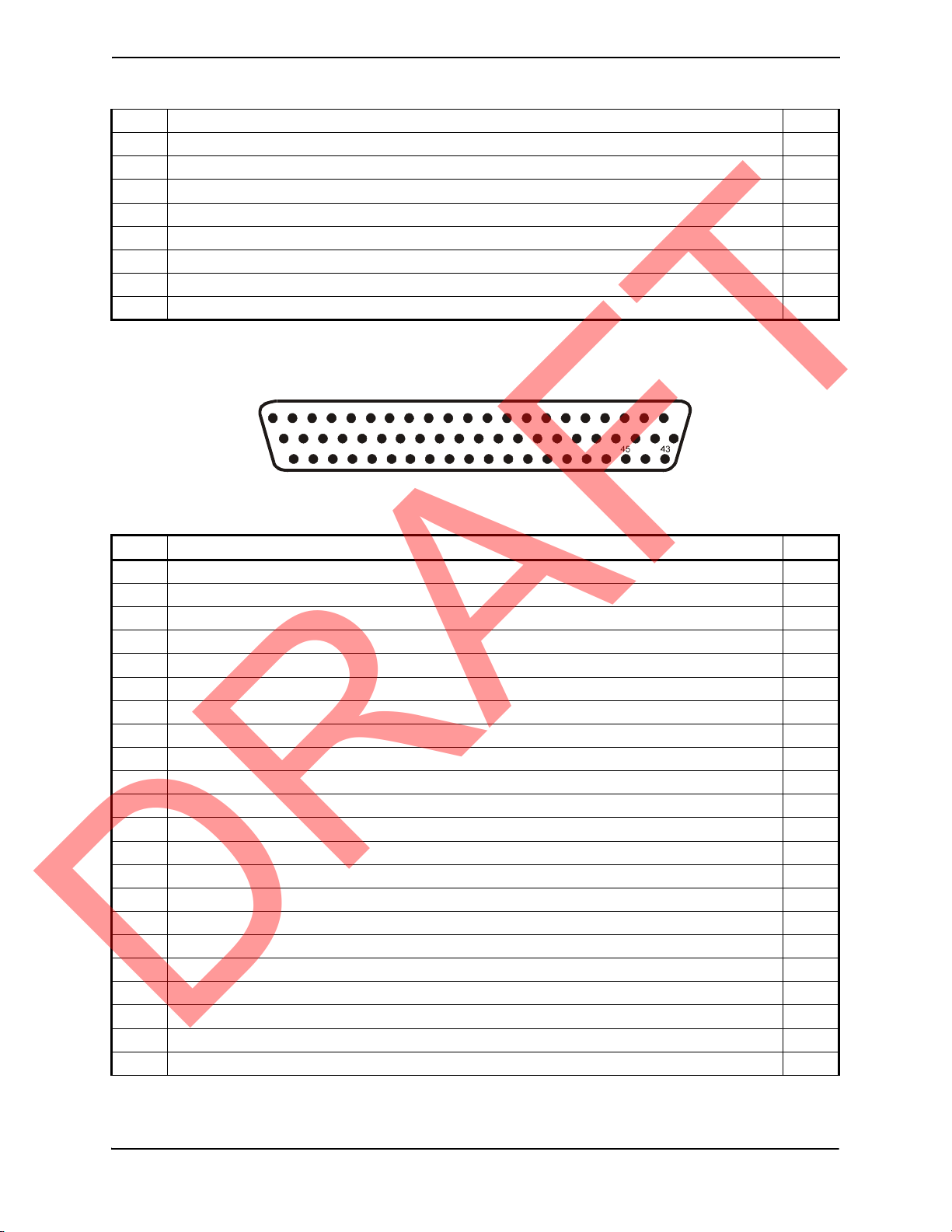
Table 4-1 P661 Connector, continued
1234567
89101112131415
222324252627282930313233343536
44464748495051
525354
5556
161718192021
373839404142
57
5859
6061
62
DRAFT
36 RESERVED --
37 SPARE --
38 SPARE --
39 RESERVED --
40 RESERVED --
41 SELCAL AUDIO AND DATA OUT HI Out
42 SELCAL AUDIO AND DATA OUT LO Out
43 SIGNAL GROUND --
44 SIGNAL GROUND --
*Denotes Active Low (Ground to activate).
4.1.2 P662 (Main)
Figure 4-2 View of J662 connector, from back of unit
Table 4-2 P662 Connector
Pin Pin Name I/O
1 POWER GROUND --
2 RS-422 IN 1 B In
3 RS-422 IN 1 A In
4 RS-422 OUT 1 B Out
5 RS-422 OUT 1 A Out
6 RS-422 IN 2 B In
7 RS-422 IN 2 A In
8 RS-422 OUT 2 B Out
9 RS-422 OUT 2 A Out
10 DISCRETE IN* 1 In
11 DISCRETE IN* 2 In
12 DISCRETE IN* 3 In
13 DISCRETE IN* 4 In
14 DISCRETE IN* 5 In
15 DISCRETE IN* 6 In
16 DISCRETE IN* 7 In
17 DISCRETE IN* 8 In
18 ARINC 429 OUT 1 A Out
19 ARINC 429 OUT 1 B Out
20 ARINC 429 OUT 2 A Out
21 ARINC 429 OUT 2 B Out
22 SPARE --
*Denotes Active Low (Ground to activate).
Page 4-2 GDR 66 Installation Manual
Revision A 190-00303-24
Page 27

Table 4-2 P662 Connector, continued
DRAFT
23 SPARE --
24 POWER GROUND --
25 SPARE --
26 POWER GROUND --
27 SPARE --
28 AIRCRAFT POWER 1 In
29 SPARE --
30 AIRCRAFT POWER 1 In
31 SPARE --
32 AIRCRAFT POWER 1 In
33 SPARE --
34 AIRCRAFT POWER 2 In
35 SPARE --
36 AIRCRAFT POWER 2 In
37 SPARE --
38 AIRCRAFT POWER 2 In
39 SPARE --
40 POWER GROUND --
41 SPARE --
42 POWER GROUND --
43 POWER GROUND --
44 SPARE --
45 SIGNAL GROUND --
46 SPARE --
47 SIGNAL GROUND --
48 SPARE --
49 ARINC 429 IN 1 A In
50 ARINC 429 IN 1 B In
51 ARINC 429 IN 2 A In
52 ARINC 429 IN 2 B In
53 ARINC 429 IN 3 A In
54 ARINC 429 IN 3 B In
55 ARINC 429 IN 4 A In
56 ARINC 429 IN 4 B In
57 ARINC 429 IN 5 A In
58 ARINC 429 IN 5 B In
59 SPARE --
60 SIGNAL GROUND --
61 SIGNAL GROUND --
62 RESERVED --
GDR 66 Installation Manual Page 4-3
190-00303-24 Revision A
Page 28

4.2 Power Functions
DRAFT
4.2.1 Aircraft Power
The GDR 66 provides two aircraft power bus inputs. Pins 28, 30, and 32 of P662 are internally connected
to form AIRCRAFT POWER 1. Pins 34, 36, and 38 of P662 are internally connected to form AIRCRAFT
POWER 2. AIRCRAFT POWER 1 and AIRCRAFT POWER 2 are “diode ORed” to provide power
redundancy. Use of three AIRCRAFT POWER pins (either AIRCRAFT POWER 1 or AIRCRAFT
POWER 2) and three POWER GROUND pins is recommended for all installations.
Table 4-3 Aircraft Power
Pin Name Connector Pin I/O
AIRCRAFT POWER 1 P662 28 In
AIRCRAFT POWER 1 P662 30 In
AIRCRAFT POWER 1 P662 32 In
AIRCRAFT POWER 2 P662 34 In
AIRCRAFT POWER 2 P662 36 In
AIRCRAFT POWER 2 P662 38 In
POWER GROUND P662 1 --
POWER GROUND P662 24 --
POWER GROUND P662 26 --
POWER GROUND P662 40 --
POWER GROUND P662 42 --
POWER GROUND P662 43 --
4.2.2 Remote Power Off
The GDR 66 powers down when the COM REMOTE POWER OFF input is active. COM REMOTE
POWER OFF is a non-configurable discrete input conforming to:
Low: 0 VDC < Vin < 3.5 VDC, OR Rin > 100k ohms (inactive)
High: 8 VDC < Vin < 36 VDC (active)
Table 4-4 Remote Power Off
Pin Name Connector Pin I/O
COM REMOTE POWER OFF P661 16 In
4.2.3 GDR System ID Program
The GDR 66 determines it’s unit number based on the status of three GDR SYSTEM ID PROGRAM*
non-configurable discrete inputs conforming to:
Low: 0 VDC < Vin < 3.5 VDC, OR Rin < 375 ohms (active)
High: 8 VDC < Vin < 36 VDC, OR Rin > 100k ohm (inactive)
Table 4-5 System ID Program
Pin Name Connector Pin I/O
GDR SYSTEM ID PROGRAM* 1 P661 20 In
GDR SYSTEM ID PROGRAM* 2 P661 22 In
GDR SYSTEM ID PROGRAM* 3 P661 24 In
Page 4-4 GDR 66 Installation Manual
Revision A 190-00303-24
Page 29

The unit number is determined by the table below:
DRAFT
Table 4-6 Unit Number Configuration
GDR SYSTEM ID
PROGRAM* 1
Open Open Open #1
Ground Open Open #2
Open Ground Open #3
Ground Ground Open #4
Open Open Ground #5
Ground Open Ground #6
Open Ground Ground #7
Ground Ground Ground INVALID, DO NOT USE
4.3 Serial Data
4.3.1 RS-422
The GDR 66 provides two RS-422 inputs and two RS-422 outputs conforming to TIA/EIA/ANSI-422-B.
RS-422 is the only interface between the GDR 66 and the rest of the Garmin system.
Pin Name Connector Pin I/O
RS-422 IN 1 B P662 2 In
RS-422 IN 1 A P662 3 In
RS-422 OUT 1 B P662 4 Out
RS-422 OUT 1 A P662 5 Out
RS-422 IN 2 B P662 6 In
RS-422 IN 2 A P662 7 In
RS-422 OUT 2 B P662 8 Out
RS-422 OUT 2 A P662 9 Out
GDR SYSTEM ID
PROGRAM* 2
Table 4-7 RS-422
GDR SYSTEM ID
PROGRAM* 3
UNIT NUMBER
4.3.2 RS-232
The GDR 66 provides one RS-232 input and one RS-232 output. The RS-232 output conforms to EIA
Standard RS-232C with an output voltage swing of at least ± 5V when driving a standard RS-232 load.
The RS-232 port is used for testing and as a back up tuning port.
Table 4-8 RS-232
Pin Name Connector Pin I/O
RS-232 OUT 1 P661 32 Out
RS-232 IN 1 P661 33 In
GDR 66 Installation Manual Page 4-5
190-00303-24 Revision A
Page 30

4.3.3 ARINC 429
DRAFT
The GDR 66 provides five configurable ARINC 429 inputs and two configurable ARINC 429 outputs
conforming to ARINC Specifications 429P1-17, 429P2-16 and 429P3-18. The ARINC 429 outputs
conform to ARINC 429 specifications when loaded with up to five standard ARINC 429 receivers. The
speed of the ARINC 429 outputs can be configured for low speed (14.29 kHz) or high speed (100 kHz).
Table 4-9 ARINC 429
Pin Name Connector Pin I/O
ARINC 429 IN 1 A P662 49 In
ARINC 429 IN 1 B P662 50 In
ARINC 429 IN 2 A P662 51 In
ARINC 429 IN 2 B P662 52 In
ARINC 429 IN 3 A P662 53 In
ARINC 429 IN 3 B P662 54 In
ARINC 429 IN 4 A P662 55 In
ARINC 429 IN 4 B P662 56 In
ARINC 429 IN 5 A P662 57 In
ARINC 429 IN 5 B P662 58 In
ARINC 429 OUT 1 A P662 18 Out
ARINC 429 OUT 1 B P662 19 Out
ARINC 429 OUT 2 A P662 20 Out
ARINC 429 OUT 2 B P662 21 Out
Page 4-6 GDR 66 Installation Manual
Revision A 190-00303-24
Page 31

4.4 Discrete I/O
DRAFT
4.4.1 Active Low Discrete Inputs
The GDR 66 provides 8 configurable discrete inputs conforming to:
Low: 0 VDC < Vin < 3.5 VDC, OR Rin < 375 ohms (active)
High: 8 VDC < Vin < 36 VDC, OR Rin > 100k ohm (inactive)
Table 4-10 Discrete Inputs
Pin Name Connector Pin I/O
DISCRETE IN* 1 P662 10 In
DISCRETE IN* 2 P662 11 In
DISCRETE IN* 3 P662 12 In
DISCRETE IN* 4 P662 13 In
DISCRETE IN* 5 P662 14 In
DISCRETE IN* 6 P662 15 In
DISCRETE IN* 7 P662 16 In
DISCRETE IN* 8 P662 17 In
4.4.2 Key Event Out
The GDR 66 provides one output to signal when the GDR 66 is transmitting, regardless of what mode the
radio is in. KEY EVENT OUT* can be used as needed to decrease the sensitivity of other COM receivers
on the aircraft when the GDR 66 is transmitting. KEY EVENT OUT* is a non-configurable discrete
output conforming to:
Active: 0 VDC < Vout < 1.0 VDC with < 20 mA sink current; sink current must be externally
limited to 20 mA max.
Inactive: Open circuit, can be pulled up to an externally sourced Vout in the range 3.3 VDC < Vout
< 36 VDC; leakage current is typically <10 uA to ground.
Table 4-11 Key Event Out
Pin Name Connector Pin I/O
KEY EVENT OUT* P661 35 Out
GDR 66 Installation Manual Page 4-7
190-00303-24 Revision A
Page 32

4.5 Audio
DRAFT
When the GDR 66 is in analog voice mode (ARINC 716 Voice), audio from the microphone and audio to
the headset can be transferred to/from the GDR 66 as analog audio or digital audio. If analog audio is used,
the COM MIC KEY* discrete input must be used. If digital audio is used all of this information is
transferred in the digital audio stream.
4.5.1 Analog Audio
4.5.1.1 Com Mic Audio
The GDR 66 provides one microphone audio input. COM MIC AUDIO has a 150 ohm AC input
impedance and supplies the microphone with a 12 V bias through 400
in the factory for 250 mVrms to modulate the transmitter at 90% nominally. The microphone gain is
adjustable during installation to increase the sensitivity to 20 mVrms or decrease the sensitivity to 2.5
Vrms.
Table 4-12 Com Mic Audio
Pin Name Connector Pin I/O
COM MIC AUDIO IN HI P661 7 In
COM MIC AUDIO IN LO (GROUND) P661 8 --
4.5.1.2 Com Audio Out
The GDR 66 provides one audio output that is intended to drive a headset or an audio panel. The rated
output is 4.90 Vrms into a 600 ohm load (40 mWavg). A volume control is available during flight to
reduce the output by at least 40 dB to 49 mVrms. COM 600 OHM AUDIO OUT is the summation of the
COM receiver audio and COM sidetone audio.
Ω +/− 20%. COM MIC AUDIO is set
Table 4-13 Com Audio Out
Pin Name Connector Pin I/O
COM 600 OHM AUDIO OUT HI P661 9 Out
COM 600 OHM AUDIO OUT LO P661 10 Out
4.5.1.3 Com Mic Key
The GDR 66 transmits the audio from the microphone (COM MIC AUDIO IN) when the COM MIC
KEY* input is active. The COM MIC KEY* should be connected to the microphones PTT output. COM
MIC KEY* is a non-configurable discrete input conforming to:
Low: 0 VDC < Vin < 3.5 VDC, OR Rin < 375 ohms (active)
High: 8 VDC < Vin < 36 VDC, OR Rin > 100k ohm (inactive)
Table 4-14 Com Mic Key
Pin Name Connector Pin I/O
COM MIC KEY* P661 4 In
Page 4-8 GDR 66 Installation Manual
Revision A 190-00303-24
Page 33

4.5.1.4 Com Remote Transfer
DRAFT
The GDR 66 provides one COM REMOTE TRANSFER* input which allows the COM Emergency State
to be entered or exited. When the GDR 66 enters Emergency State, it automatically switches to AM COM
mode and tunes to the emergency channel, 121.500 MHz. When in Emergency State, the GDR 66 ignores
inputs from the front panel controls for COM selections and cannot be used for digital data link.
The COM REMOTE TRANSFER* input controls Emergency State via one of two modes: “Hold-toAcitvate” mode and “On/Off” mode. A GDR 66 aircraft configuration parameter selects the mode as well
as the activation time for Hold-to-Acitvate mode. In Hold-to-Acivate mode, the Emergency State is
entered when the COM REMOTE TRANSFER* input is held active for the configured time, and is exited
immediately when the COM REMOTE TRANSFER* input becomes active after having been inactive. In
On/Off mode, COM REMOTE TRANSFER* acts as an on/off switch for Emergency State, which is
entered immediately when COM REMOTE TRANSFER* becomes active, and is exited immediately
when COM REMOTE TRANSFER* becomes inactive.
Low: 0 VDC < Vin < 3.5 VDC, OR Rin < 375 ohms (active)
High: 8 VDC < Vin < 36 VDC, OR Rin > 100k ohm (inactive)
Table 4-15 Com Remote Transfer
Pin Name Connector Pin I/O
COM REMOTE TRANSFER* P661 12 In
4.5.2 ACARS/SELCAL
4.5.2.1 SELCAL Audio and ACARS Data Out
The GDR 66 provides one SELCAL audio/ACARS data output that can either be used for SELCAL or
VDL Mode 0 (ARINC 716 Data). The rated output is 2.45 Vrms into a 600 ohm load (10 mWavg). The
gain is adjustable during installation to decrease the output by at least 40 dB to 24.5 mVrms. A gain setting
of -7.0 dB (1.2 Vrms minimum) is recommended. Refer to EQF for certification considerations for this
output.
Table 4-16 SELCAL Audio and ACARS Data Out
Pin Name Connector Pin I/O
SELCAL AUDIO AND DATA OUT HI P661 41 Out
SELCAL AUDIO AND DATA OUT LO P661 42 Out
GDR 66 Installation Manual Page 4-9
190-00303-24 Revision A
Page 34

This page intentionally left blank
DRAFT
Page 4-10 GDR 66 Installation Manual
Revision A 190-00303-24
Page 35
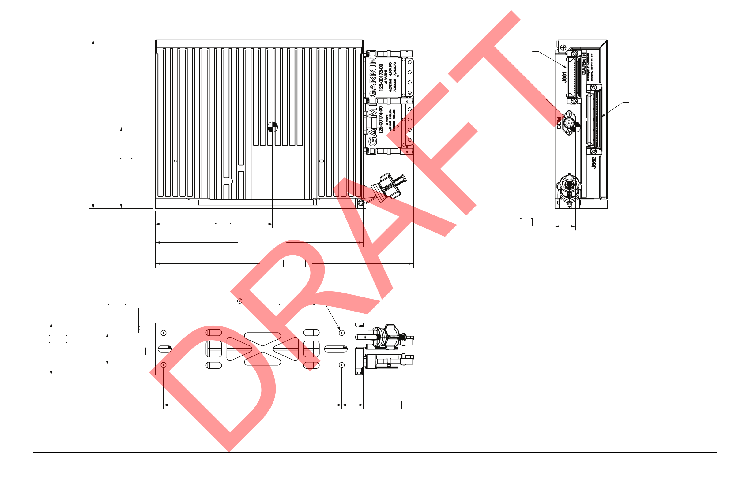
APPENDIX A Outline and Installation Drawings
.8 20
CG
81
CG
3.2
117
4.6
CG
P662
P661
COM
(TNC CONNECTOR)
NOTES:
DIMENSIONS: INCHES[mm]1.
DIMENSIONS ARE SHOWN FOR REFERENCE ONLY2.
MOUNTING HOLES FOR #10 PAN HEAD OR HEX HEAD FASTENERS (4 PLACES)3.
SEE NOTE 3
±.005
±0.25
±0.13
±.010 177.8
2X
7.00
2X
5.33
1.26
52.3
.210
10.2
2.06
±.010
.40
32.0±0.25
4X
2X
2X .85 21.6
10.14 257.6
6.62 168.1
8.17 207.5
DRAFT
GDR 66 Installation Manual Page A-1
190-00303-24 Revision A
Figure A-1 GDR 66 Outline Drawing
Page 36
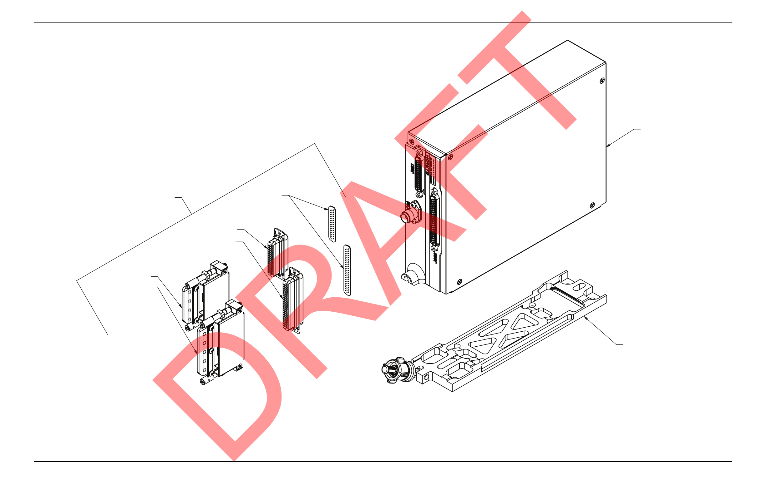
APPENDIX A Outline and Installation Drawings
011-02477-00
330-00776-44
2.
GDR 66 UNIT
011-02303-00
GDR66 RACK
011-02304-00
011-01855-02
011-01855-03
330-00776-62
NOTE 1
CONNECTOR KIT
NOTES:
GASKETS ARE PART OF 330-00776-44 AND 330-00776-62. INSTALL GASKETS OVER PINS.1.
REFER TO 190-00313-11 FOR ADDITIONAL PARTS LISTS.
NOTE 2
DRAFT
Figure A-2 GDR 66 Connector/Rack Assembly Drawing
GDR 66 Installation Manual Page A-2
190-00303-24 Revision A
Page 37
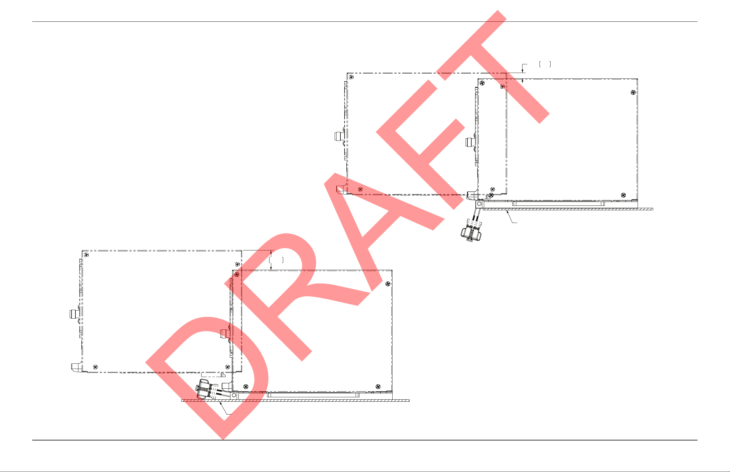
APPENDIX A Outline and Installation Drawings
MINIMUM RECOMMENDED INSTALLATION AND REMOVAL CLEARANCE
WITH LOCKDOWN NOT OVERHANGING MOUNTING SHELF
MOUNTING SHELF
1.00 25.4
MINIMUM RECOMMENDED INSTALLATION AND REMOVAL CLEARANCE
WITH LOCKDOWN OVERHANGING MOUNTING SHELF
MOUNTING SHELF
.30 7.6
DRAFT
GDR 66 Installation Manual Page A-3
190-00303-24 Revision A
Figure A-3 GDR 66 Minimum Installation/Removal Clearance
Page 38
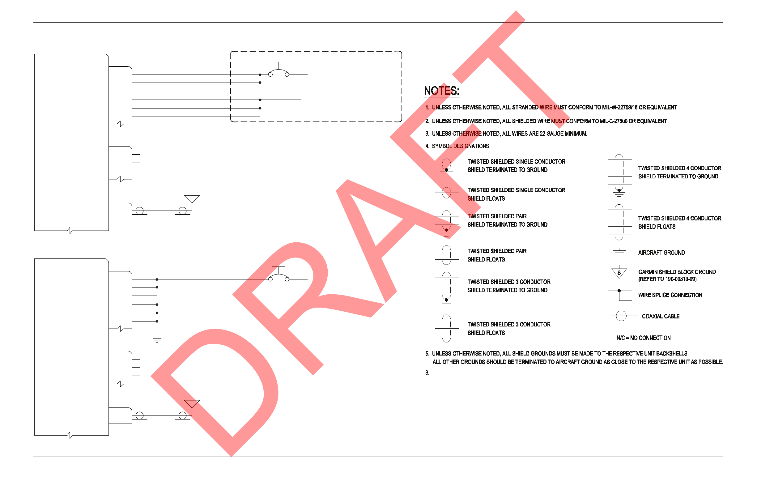
APPENDIX B Interconnect Examples
DRAFT
GDR 66 DIGITAL RADIO
AIRCRAFT POWER 1
AIRCRAFT POWER 1
AIRCRAFT POWER 1
POWER GROUND
POWER GROUND
POWER GROUND
GDR SYSTEM ID PROGRAM* 1
GDR SYSTEM ID PROGRAM* 2
GDR SYSTEM ID PROGRAM* 3
COM ANTENNA
P662
28
30
32
1
24
26
P661
20
22
24
J1
GDR 66
10A
TO 14/28 VDC AIRCRAFT POWER
SEE NOTE 7
GDR 66 DIGITAL RADIO
AIRCRAFT POWER 1
AIRCRAFT POWER 1
AIRCRAFT POWER 1
POWER GROUND
POWER GROUND
POWER GROUND
GDR SYSTEM ID PROGRAM* 1
GDR SYSTEM ID PROGRAM* 2
GDR SYSTEM ID PROGRAM* 3
COM ANTENNA
P662
28
30
32
1
24
26
P661
20
22
24
J1
18 AWG
18 AWG
18 AWG
18 AWG
18 AWG
18 AWG
N/C
N/C
N/C
16 AWG
16 AWG
GDR 66
10A
TO 14/28 VDC AIRCRAFT POWER
TO MINIMIZE VHF DIGITAL TRANSMISSION INTERFERENCE (ACARS/CPDLC) WITH RECEPTION OF VHF VOICE
COMMUNICATION, IT IS RECOMMEDED THAT GIA 63W -40 UNITS SHOULD BE USED IN ALL INSTALLATIONS USING
A GDR 66.
7. GIA 63W -00 AND -01 UNITS CANNOT BE USED WITH THE GDR 66.
Figure B-1 GDR 66 Power and Antenna Interconnect Example
GDR 66 Installation Manual Page B-1
190-00303-24 Revision A
Page 39
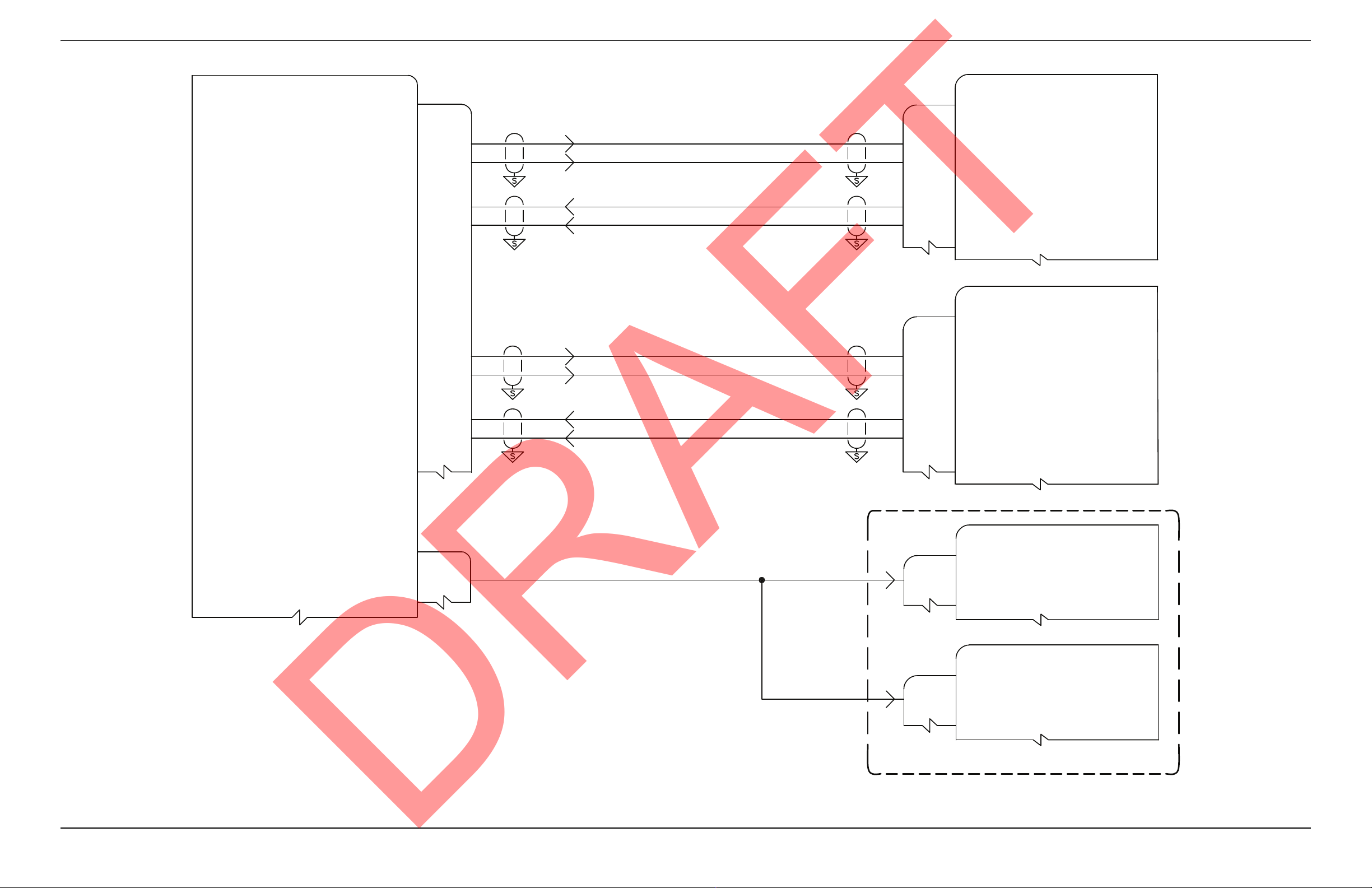
APPENDIX B Interconnect Examples
5
4
3
2
GDR 66 DIGITAL RADIO
P662
RS 422 OUT 1A
RS 422 OUT 1B
RS 422 IN 1A
RS 422 IN 1B
No. 1 GSD 41
DATA CONCENTRATOR
1P412
26
25
MAIN2 RS-485/RS-422 13A
MAIN2 RS-485/RS-422 13B
27
28
MAIN2 RS-485/RS-422 14A
MAIN2 RS-485/RS-422 14B
No. 2 GSD 41
DATA CONCENTRATOR
2P412
6
5
MAIN2 RS-485/RS-422 3A
MAIN2 RS-485/RS-422 3B
7
8
MAIN2 RS-485/RS-422 4A
MAIN2 RS-485/RS-422 4B
9
8
7
6
RS 422 OUT 2A
RS 422 OUT 2B
RS 422 IN 2A
RS 422 IN 2B
No. 1 GIA 63W
1P601
11
TRANSMIT INTERLOCK*
No. 2 GIA 63W
2P601
11
TRANSMIT INTERLOCK*
P661
35
KEY EVENT OUT*
SEE NOTE 6
DRAFT
Figure B-2 GDR 66 VDL Mode 2 Interconnect Example
GDR 66 Installation Manual Page B-2
190-00303-24 Revision A
Page 40
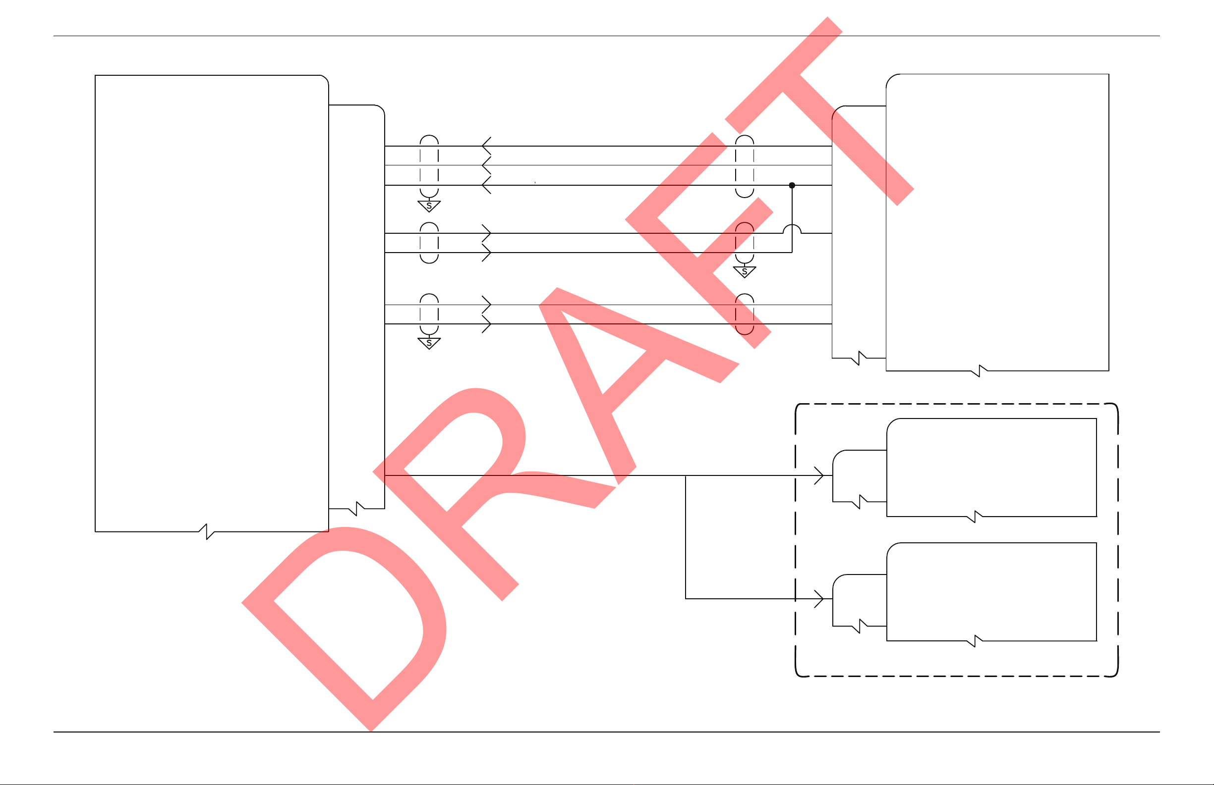
APPENDIX B Interconnect Examples
DRAFT
GDR 66 DIGITAL RADIO
COM MIC KEY*
COM MIC AUDIO IN HI
COM MIC AUDIO IN LO
COM 600 OHM AUDIO OUT HI
COM 600 OHM AUDIO OUT LO
SELCAL AUDIO AND DATA OUT HI
SELCAL AUDIO AND DATA OUT LO
P661
4
7
8
9
10
41
42
1P3471
33
32
13
12
31
52
No. 1 GMA 36
AUDIO PROCESSOR
TRANSCEIVER 2 MIC KEY* OUT
TRANSCEIVER 2 MIC AUDIO OUT HI
TRANSCEIVER 2 AUDIO LO
TRANSCEIVER 2 AUDIO IN HI
RECEIVER 4 AUDIO IN HI
RECEIVER 4 AUDIO IN LO
KEY EVENT OUT*
35
1P601
11
2P601
11
SEE NOTE 6
No. 1 GIA 63W
TRANSMIT INTERLOCK*
No. 2 GIA 63W
TRANSMIT INTERLOCK*
Figure B-3 GDR 66 Analog Voice Mode Interconnect Example
GDR 66 Installation Manual Page B-3
190-00303-24 Revision A
 Loading...