

Page 1
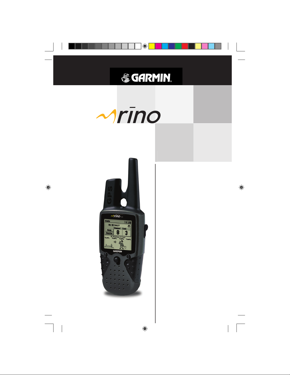
130
2-way radio &
personal navigator
owner’s
manual
and
reference
guide
®
Preliminary
190-00284-00_Prelim_FCC.indd a 9/18/2003, 3:50:25 PM
Page 2
© Copyright 2003 Garmin Ltd. or its subsidiaries
Garmin International, Inc.
1200 E 151st Street, Olathe, Kansas 66062 U.S.A.
Tel. 913/397.8200
Fax. 913/397.8282
Garmin (Europe) Ltd.
Unit 5, The Quadrangle, Abbey Park Industrial Estate, Romsey, SO51 9AQ U.K.
Tel. 44/1794.519944
Fax.44/1794.519222
Garmin Corporation
No. 68, Jangshu 2nd Road, Shijr, Taipei County, Taiwan
Tel. 886/2.2642.9199
Fax. 886/2.2642.9099
All rights reserved. Except as expressly provided herein, no part of this manual may be
reproduced, copied, transmitted, disseminated, downloaded or stored in any storage
medium, for any purpose without prior written consent of Garmin. Garmin hereby
grants permission to download a single copy of this manual onto a hard drive or other
electronic storage medium to be viewed for personal use, provided that such electronic
or printed copy of this manual or revision must contain the complete text of this copyright notice and provided further that any unauthorized commercial distribution of this
manual is strictly prohibited.
Information in this manual is subject to change without notice. Garmin reserves the
right to change or improve its products and to make changes in the content without
obligation to notify any person or organization of such changes. Visit the Garmin web
site (www.Garmin.com) for current updates and supplemental information concerning
the use and operation of this and other Garmin products.
Garmin™, AutoLocate™,
®
Rino
subsidiaries
September 2003 Part Number 190-00284-00 Rev. A Printed in Taiwan
PreliminaryPreliminary
, MapSource®, BlueChart®, and Click Stick® are trademarks of Garmin Ltd.
and may not be used
Personal Navigator™,
without the express permission of Garmin.
and TracBack™ are registered trademarks,
or its
190-00284-00_Prelim_FCC.indd b 9/18/2003, 3:50:41 PM
Page 3
Thank you for choosing the Garmin Rino (Radio Integrated with Navigation for the Outdoors). To get the most
from your new Rino, take time to read through the Quick
Start Guide fi rst, then this owner’s manual to understand
all of the operating features.
This Reference Manual describes the Main Pages of the
Rino and their options in detail. The Quick Start Guide
describes the process of navigating the Main Pages and the
Option Menus, along with some basic unit operations to
familiarize you with your new Rino right out of the box.
While the Reference Manual provides some direction on
how to select and change items, its main intention is to
describe each Main Page and its Option Menu in detail.
This manual is organized into three sections.
The Introduction section provides FCC, safety, warranty, product registration information, and the Table of
Contents.
The Main Pages section (listed in same order as
viewed on screen) provides details about using the features
of the Rino according to topic. The explanations for each
feature in this section are divided into: (1) An overview
that discusses the feature and how it functions and (2) A
detailed Step-by-Step instruction for using the feature.
The Appendices include Specifi cations, Accesso-
ries, Data Field Defi nitions, MapSource information, a
Troubleshooting Guide, Wiring Diagram and a Time
Offset Chart followed by the Index.
Check to see that your package includes the following
items. If any parts are missing, contact your Garmin
dealer immediately.
Standard Package Contents:
1 Rino Unit
1 Belt Clip
1 Wrist Strap
1 Owner’s Manual
1 Quick Start Guide
1 PC Interface Cable (Rino 130 Only)
Preliminary
Introduction
About This
Manual /
Packing List
190-00284-00_Prelim_FCC.indd i 9/18/2003, 3:50:42 PM
i
Page 4
Introduction
FCC Compliance
&
GMRS Licensing
Preliminary
FCC Compliance
The Rino 130 complies with Part 15 of the FCC regulations and with Canadian ICES-003 for Class B digital
devices. Operation of this device is subject to the following
conditions: (1) This device may not cause harmful interference, and (2) this device must accept any interference
received, including interference that may cause undesired
operation.
This equipment generates, uses and can radiate
radio frequency energy and, if not installed and used in
accordance with the instructions, may cause harmful
interference to radio communications. However, there
is no guarantee that interference will not occur in a particular installation. If this equipment does cause harmful
interference to radio or television reception, which can be
determined by turning the equipment off and on, the user
is encouraged to try to correct the interference by one or
more of the following measures:
• Reorient or relocate the receiving antenna.
• Increase the separation between the equipment
and receiver.
• Connect the equipment into an outlet on a circuit
different from that to which the receiver is connected.
• Consult the dealer or an experienced radio/TV
technician for help.
The Rino 130 does not contain any user-serviceable
parts. Repairs should only be made by an authorized
Garmin service center. Unauthorized repairs or modifi cations could result in permanent damage to the equipment,
and void your warranty and your authority to operate this
device.
FCC Licensing Information
The Rino 130 two-way radio operates on General Mobile Radio Service (GMRS) frequencies that are regulated
by the Federal Communications Commission (FCC) in the
United States. In order to transmit on these frequencies,
you are required to obtain a license from the FCC. An
individual 18 years of age or older, who is not a representative of a foreign government, is eligible to apply for a
ii
190-00284-00_Prelim_FCC.indd ii 9/18/2003, 3:50:42 PM
Page 5
Introduction
GMRS license. To apply for a GMRS license, you will need
FCC Form 605 (605 Main Form and Schedule F) and
FCC Form 159. You can download the application forms
from the FCC web site at http://www.fcc.gov/Forms/. You
can also request them through the FCC forms hotline at
1-800-418-FORM (1-800-418-3676). You can fi le Form
605 on-line at http://wireless.fcc.gov/uls/. There is a fi ling
fee associated with this application, which may change
from time to time. For information on fees, see the FCC
fee information web page at http://wireless.fcc.gov/csinfo/
feeinfo.html.
GMRS is not currently approved for use in Canada. For
use in countries outside of the U.S., please check with that
government for any restrictions of FRS or GMRS use.
For questions concerning the license application, contact the FCC at 1-888-CALL-FCC (1-888-225-5322)
Warnings and Precautions
The GPS system is operated by the United States
government, which is solely responsible for its accuracy
and maintenance. The system is subject to changes which
could affect the accuracy and performance of all GPS
equipment. Although the Garmin Rino 130 is a precision
electronic NAVigation AID (NAVAID), any NAVAID can be
misused or misinterpreted and, therefore, become unsafe.
The electronic chart is an aid to navigation and is
designed to facilitate the use of authorized government
charts, not replace them. Only offi cial government charts
and notices to mariners contain all information needed for
safe navigation—and, as always, the user is responsible for
Preliminary
their prudent use.
Use the Rino 130 at your own risk. To reduce the risk
of unsafe operation, carefully review and understand all
aspects of this Owner’s Manual—and thoroughly practice
operation using the Demo mode prior to actual use. When
in actual use, carefully compare indications from the Rino
130 to all available navigation sources, including the
information from other NAVAIDs, visual sightings, charts,
etc. For safety, always resolve any discrepancies before
continuing navigation.
Warnings &
Precautions
MAP DATA INFORMATION:
One of the goals of Garmin is
to provide customers with the
most complete and accurate
cartography that is available to
us at a reasonable cost. We use
a combination of governmental
and private data sources, which
we identify (as required) in
product literature and copyright
messages displayed to the
consumer. Virtually all data
sources contain inaccurate
or incomplete data to some
degree. This is particularly true
outside the United States, where
complete and accurate digital
data is either not available or
prohibitively expensive.
CAUTION: IT IS THE USER’S
RESPONSIBILITY TO USE
THIS PRODUCT PRU-
DENTLY. THIS PRODUCT
IS INTENDED TO BE USED
ONLY AS A NAVIGATIONAL
AID AND MUST NOT BE
USED FOR ANY PURPOSE
REQUIRING PRECISE
MEASUREMENT OF DIREC-
TION, DISTANCE, LOCA-
TION, OR TOPOGRAPHY.
,
190-00284-00_Prelim_FCC.indd iii 9/18/2003, 3:50:42 PM
iii
Page 6
Introduction
Warnings &
Precautions
Preliminary
iv
Important: Read this information before using your Rino.
Exposure to Radio Frequency Signals - Your wire-
less handheld radio is a low power radio transmitter
and receiver. When it is ON, it receives and also sends
out radio frequency (RF) signals.In August 1996, The
Federal Communications Commissions (FCC) adopted
RF exposure guidelines with safety levels for handheld
wireless radios. Those guidelines are consistent with safety
standards previously set by both U.S. and international
standards bodies: American National Standards Institute
(ANSI) IEEE. C95.1-1992; National Council on Radiation Protection and Measurement (NCRP) Report 86;
International Commission on Non-Ionizing Radiation
Protection (ICNIRP) 1996. Those standards were based
on comprehensive and periodic evaluations of the relevant
scientifi c literature. For example, over 130 scientists,
engineers, and physicians from universities, government
health agencies, and industry reviewed the available body
of research to develop the ANSI Standard (C95.1).The
design of your radio complies with the FCC guidelines
(and those standards).
Antenna Care - Use only the supplied or an approved
replacement antenna. Unauthorized antennas, modifi cations, or attachments could damage the radio and may
violate FCC regulations. Do not use any radio that has a
damaged antenna, because if it comes into contact with
your skin, a minor burn can result.
Bectronic Devices - Most modern electronic equipment
is shielded from RF signals. However, certain equipment
may not be shielded against the RF signals from your
wireless radio.
Pacemakers - The Health Industry Manufacturers Association recommends that a minimum separation of six
inches (6”) be maintained between a handheld wireless
radio and a pacemaker to avoid potential interference with
the pacemaker. These recommendations are consistent
with the independent research by and recommendations
of Wireless Technology Research. Persons with pacemakers should ALWAYS keep the radio more than six inches
from their pacemaker when the radio is turned ON should
190-00284-00_Prelim_FCC.indd iv 9/18/2003, 3:50:43 PM
Page 7
Introduction
not carry the radio in a breast pocket should use the ear
opposite the pacemaker to minimize the potential for
interference should turn the radio OFF immediately if you
have any reason to suspect that interference is taking place
Hearing Aids - Some digital wireless radios may interfere
with some hearing aids. In the event of such interference,
you may want to consult your hearing aid manufacturer to
discuss alternatives.
Other Medical Devices - If you use any other personal
medical device, consult the manufacturer of your device
to determine if it is adequately shielded from external RF
energy. Your physician may be able to assist you in obtaining this information.
Turn your radio OFF in health care facilities when any
regulations posted in these areas instruct you to do so.
Hospitals or health care facilities may be using equipment
that could be sensitive to external IRF energy.
Vehicles - RF signals may affect improperly installed or
inadequately shielded electronic systems in motor vehicles.
Check with the manufacturer or its representative regarding your vehicle. You should also consult the manufacturer
of any equipment that has been added to your vehicle.
Posted Facilities - Turn your radio OFF in any facility
where posted notices so require.
Commercial Aircraft - Many commercial airlines prohibit
the use of FRS radios on board. Switch OFF your radio
before boarding an aircraft or check the airline rules.
Blasting Areas - To avoid interfering with blasting operations, turn your radio OFF when in a “blasting area” or in
areas posted: “Turn off two-way radio.” Obey all signs and
instructions.
Potentially Explosive Atmospheres - Turn your radio
OFF and do not remove your battery when you are in any
area with a potentially explosive atmosphere. Obey all
signs and instructions. Sparks from your battery in such
areas could cause an explosion or fi re resulting in bodily
injury or even death.
Areas with a potentially explosive atmosphere are often,
but not always clearly marked. They include fueling
ares such as gasoline stations, below deck on boats, fuel
or chemical transfer or storage facilities; vehicles using
liquefi ed petroleum gas (such as propane or butane); areas
where the air contains chemicals or particles, such as
190-00284-00_Prelim_FCC.indd v 9/18/2003, 3:50:43 PM
Preliminary
Warnings &
Precautions
v
Page 8

Introduction
LIMITED WARRANTY
This Garmin product is warranted to be free from defects in materials or workmanship for one year from the date of purchase. Within this period, Garmin will at its
sole option, repair or replace any components that fail in normal use. Such repairs or
replacement will be made at no charge to the customer for parts or labor, provided that
the customer shall be responsible for any transportation cost. This warranty does not
cover failures due to abuse, misuse, accident or unauthorized alteration or repairs.
THE WARRANTIES AND REMEDIES CONTAINED HEREIN ARE EXCLUSIVE
AND IN LIEU OF ALL OTHER WARRANTIES EXPRESS OR IMPLIED OR STATUTORY, INCLUDING ANY LIABILITY ARISING UNDER ANY WARRANTY OF
MERCHANTABILITY OR FITNESS FOR A PARTICULAR PURPOSE, STATUTORY OR
OTHERWISE. THIS WARRANTY GIVES YOU SPECIFIC LEGAL RIGHTS, WHICH
MAY VARY FROM STATE TO STATE.
IN NO EVENT SHALL Garmin BE LIABLE FOR ANY INCIDENTAL, SPECIAL,
INDIRECT OR CONSEQUENTIAL DAMAGES, WHETHER RESULTING FROM THE
USE, MISUSE, OR INABILITY TO USE THIS PRODUCT OR FROM DEFECTS IN THE
PRODUCT. Some states do not allow the exclusion of incidental or consequential damages, so the above limitations may not apply to you.
Garmin retains the exclusive right to repair or replace the unit or software or offer
a full refund of the purchase price at its sole discretion. SUCH REMEDY SHALL BE
YOUR SOLE AND EXCLUSIVE REMEDY FOR ANY BREACH OF WARRANTY.
Products sold through online auctions are not eligible for rebates or other special offers
from Garmin. Online auction confi rmations are not accepted for warranty verifi cation.
To obtain warranty service, an original or copy of the sales receipt from the original
retailer is required. Garmin will not replace missing components from any package
purchased through an online auction.
To obtain warranty service, contact your local Garmin authorized dealer. Or call
Garmin Customer Service at one of the numbers shown below, for shipping instructions
and an RMA tracking number. The unit should be securely packed with the tracking
number clearly written on the outside of the package. The unit should then be sent,
freight charges prepaid, to any Garmin warranty service station. A copy of the original
sales receipt is required as the proof of purchase for warranty repairs.
Garmin International, Inc. Garmin (Europe) Ltd.
1200 East 151st Street Unit 4, The Quadrangle,
Olathe, Kansas 66062, U.S.A Abbey Park Industrial Estate
Phone: 913/397.8200 Romsey, SO51 9AQ, U.K.
USA Only: 800/800.1020 Phone: 44/1794.519944
FAX: 913/397.0836 FAX: 44/1794.519222
The Garmin Rino 130 has no user-serviceable parts. Should you ever encounter a
problem with your unit, please take it to an authorized Garmin dealer for repairs.
The Rino 130 is fastened shut with screws. Any attempt to open the case to change
vi
or modify the unit in any way will void your warranty and may result in permanent
damage to the equipment.
Preliminary
190-00284-00_Prelim_FCC.indd vi 9/18/2003, 3:50:44 PM
Page 9
Software License Agreement
BY USING THE Rino 130, YOU AGREE TO BE
BOUND BY THE TERMS AND CONDITIONS OF THE
FOLLOWING SOFTWARE LICENSE AGREEMENT.
PLEASE READ THIS AGREEMENT CAREFULLY.
Garmin grants you a limited license to use the software
embedded in this device (the “Software”) in binary executable form in the normal operation of the product. Title,
ownership rights and intellectual property rights in and to
the Software remain in Garmin.
You acknowledge that the Software is the property of
Garmin and is protected under the United States of America copyright laws and international copyright treaties.
You further acknowledge that the structure, organization
and code of the Software are valuable trade secrets of
Garmin and that the Software in source code form remains
a valuable trade secret of Garmin. You agree not to
decompile, disassemble, modify, reverse assemble, reverse
engineer or reduce to human readable form the Software
or any part thereof or create any derivative works based
on the Software. You agree not to export or re-export the
Software to any country in violation of the export control
laws of the United States of America.
Software License
Introduction
Agreement &
Registration
Customer Service Product Registration
Help us better support you by completing our on-line
registration today!
Have the serial number of your Rino 130 handy and
connect to our web site (www.Garmin.com). Look for the
Product Registration link on the Home page. Also, be sure
to record your serial number in the area provided below.
NOTE: If you have previously registered a Garmin
product purchase, we invite you to re-register using our
NEW on-line system. Many services provided by our new
product registration system are now being automated and
re-registering your purchase ensures you the best possible
support from Garmin.
190-00284-00_Prelim_FCC.indd vii 9/18/2003, 3:50:44 PM
Preliminary
Serial Number:
*
*
+
Why should you register your
Garmin GPS unit:
• Notifi cation of New Products
• Lost or Stolen unit tracking
vii
Page 10
Table of Contents
Introduction
About This Manual.............................................i
FCC Compliance Statement...............................ii
FCC Licensing for GMRS...............................ii-iii
Warnings and Precautions.............................iii-v
Warranty...........................................................vi
Software License Agreement.............................vii
Product Registation..........................................vii
Table of Contents............................................viii
The Main Pages
Unit Overview ....................................................1
Radio Page
The Main Page..................................................2
Status Bar....................................................3
My ID......................................................3-4
Channels and Codes................................4-5
Scan and Montior....................................5-6
Setup Radio.............................................7-8
Informational Picture.............................9-10
Peer-to-Peer..........................................11-13
Map Page
The Main Page..................................................14
Zooming In/Out......................................15
Map Page Options...................................16
Panning the Ma
Stop Navigation......................................18
Show........................................................18
Data Fields..............................................18
Map Page Setup..................................19-20
Measure Distance....................................20
Navigation Page
The Main Page..................................................21
Navigation Page Options...................22-23
Data Fields..............................................23
p ..................................17
Preliminary
Trip Computer Page
The Main Page.............................................24-25
Main Menu Page
The Main Page..................................................26
Using the Main Menu............................27
Marking Your Location as a Waypoint......28
Creating a Waypoint.................................29
Projecting a Waypoint..............................30
Editing Waypoints..
....................
.............30
viii
Saving as a Waypoint............................31
The Find ‘N Go Menu.............................31-37
Finding a Waypoint...............
Finding a Contact..................
Finding a City..........................................33
Finding an Exit....
Finding a Point of Interest................34-35
Finding an Address or Intersection...35-36
Finding a Last Found Place....
Using a Goto.........
Routes Page.............................................39-44
Creating and Using A Route..................39
Editing a Route................................40-42
Ad
Navigating a Route............................43-44
Tracks Page....................
Proximity Page.........................
Satellite Page..................
Setup Pages...................
Time Page.............
Units Page..........................................52-53
Display Page......
Heading Page..........................................54
Interface Page.....
System Page.............................................56
Calendar Page..............
Alarm Clock Page..............
Calculator Page.............
Stopwatch Page..............
Sun and Moon Page.....................................60
Hunt and Fish Page......................................60
Area Calculation Page....
Games Page.........................
Appendices
Appendix A: What is FRS?....................................64
Appendix B: Specifi cations..................................66
Appendix C: Accessories......................................67
Appendix D: MapSource Setup...........................68
Appendix E: Troubleshooting.........................69-70
Appendix F: Data Field Defi nitions..................71-72
Appendix G: Wiring Diagram..............................73
Appendix H: Frequency Chart.............................74
Index............................................................75-76
.......
d/Edit fr
om the Route Map P
........................
........
........32
........
........32
...........
.................33-34
......
........37
................................38
age.
42-43
.........
.................45-46
....
.................47
.........
.................48-50
............
...............51-56
..............
....................51
..............54
..............
......................55
...........................
......................
...........................
.........................
..........................
..................
.....57
.....58
.....58
.....59
.....61
...62-63
190-00284-00_Prelim_FCC.indd viii 9/18/2003, 3:50:45 PM
Page 11
Rino 130 - Overview
The Rino 130 (Radios Integrated with Navigation for
the Outdoors) is a 7.6 ounce, 12 channel GPS-enabled
handheld device with integrate radio functionality to provide two-way communications for up to two miles using
14 FRS (Family Radio Service) and 8 high-performance
GMRS (General Mobile Radio Service) channels for up to
fi ve miles. You can keep track of up to 50 other contacts
from other Rino users.
The Rino 130 has seven keys located on the unit that
allow the user to quickly access all of the units functions.
The Rino 130 has a 160 X 160 pixel, 4 level gray monochrome display for easy viewing.
The Rino can store up to 500 waypoints with a 10character name and graphic symbol. The active track log
will store up to 3000 points and allow you to save up to
20 tracks with 250 points per track.
Built-in cartography of a North American base map
that includes Interstate and State Highways and Exit
Information. Using MapSource™, Garmin’s map data
software (not included), you could choose to have the
Rino 130 display up to 8MB of a variety of different
map information. We currently offer several mapping
options that are compatible with the Rino 130 including our MetroGuide, Topo, Fishing Hot Spots, and
BlueChart data. Check your local dealer or our web site
(www.Garmin.com) for a complete listing of MapSource
products.
Garmin designed your Rino 130 with the user in
mind. The Rino 130 is waterproof to IPX7 standards and
is rugged enough to endure the most trying use, and
Garmin’s friendly user interface will allow you to start
navigating with your new GPS in no time. Your Rino 130
can provide one more critical benefi t, peace of mind.
With your Rino 130 you will know where you are, where
you’ve been and where you’re going. And since you’ll
always know the way back home, you can concentrate on
what you set out to do, explore the great outdoors.
Preliminary
Main Pages
Features
190-00284-00_Prelim_FCC.indd 1 9/18/2003, 3:50:45 PM
1
Page 12
Radio Page
The Main Page
Radio Page
Preliminary
Hold PAGE to release the
keylock.
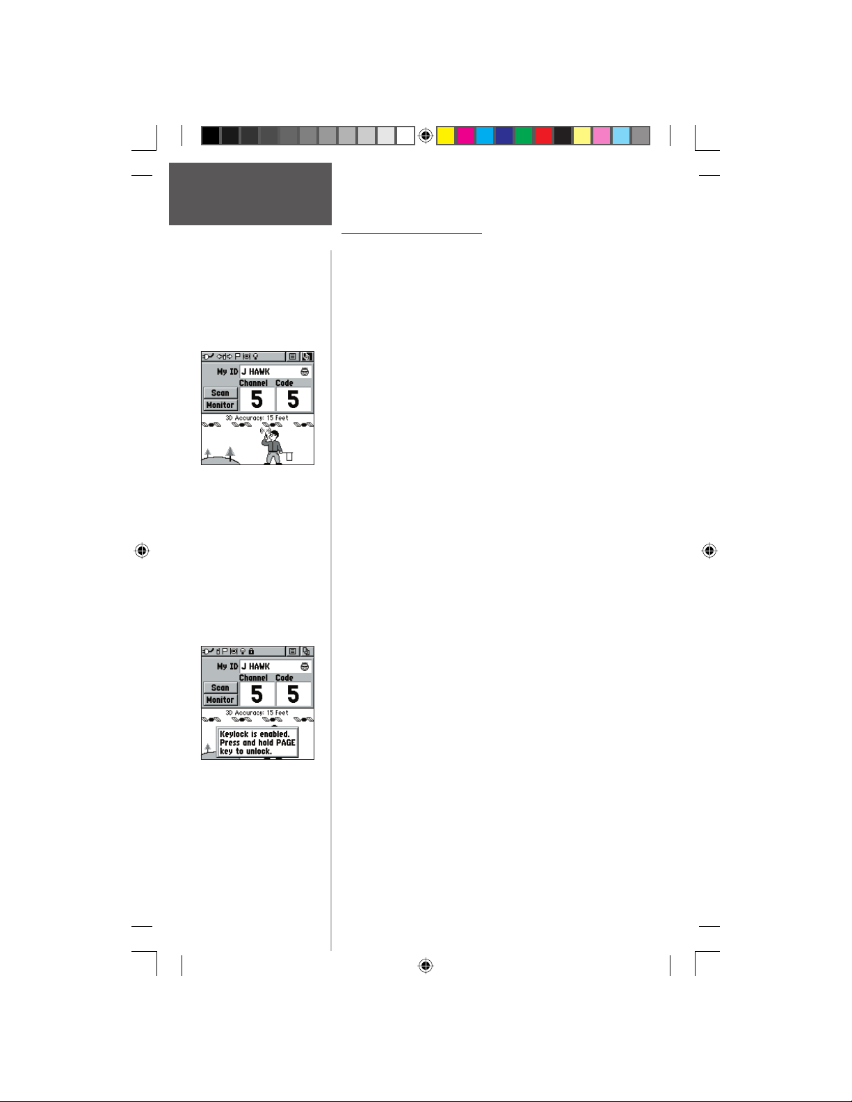
Radio Page - Overview
The Radio Page is the fi rst of the default Main Pages.
This page provides the user interface for FRS (Family Radio
Service) and GMRS (General Mobile Radio Service) radio
operations. Use this page to control and setup the radio,
view current settings and see informational graphics of the
radio’s operation.
The ‘My ID’ fi eld allows you to customize a name and
chose a symbol that will appear on other Rino units as you
communicate with them.
The Rino has a total of 22 channels and 38 squelch
codes to select from using the ‘Channel’ and ‘Code’ fi elds.
Channels 1-14 are for FRS and 15-22 are for GMRS. GMRS
(disabled by default) frequencies are regulated by the FCC
(Federal Communications Commission). In order to transmit on these frequencies, you are required to obtain a license
from the FCC (see pg. ii-iii). The ‘Scan’ option allows you to
scan through the channels for voice activity. The ‘Monitor’
option lets you monitor a single channel for any activity,
including static and weak voice signals. You might choose
this option if a signal is getting out of range or weak.
The Informational Picture on the bottom half of screen
features Garmin’s Mr. Mark Waypoint to show current GPS
& radio status (see pg. 9) and radio actions. As you operate
the unit, the graphics will change depending on what actions you are taking or unit settings.
The Status Bar at the top of the page will show icons for
current radio settings and operation. The Options Menu, on
the right side of the Status Bar, has settings for Setting up the
radio, defi ning a scanlist, and turning the GPS or radio On/
Off. The Main Page Menu, on the far right side of the Status
Bar, allows you to jump to any of the available Main Pages.
The Rino buttons (Except the TALK key) may be keylocked in order to avoid unwanted keypresses.
To lock/unlock the keys :
1. Press IN and hold the CLICK STICK to access the
Shortcut Menu, then highlight ‘Enable Keylock’ and
press IN. To unlock, press and hold the PAGE key until
‘Keylock Disabled’ is displayed (about 5 seconds)
2
190-00284-00_Prelim_FCC.indd 2 9/18/2003, 3:50:46 PM
Page 13

Status Bar - Overview
The Status Bar at the top of the screen will display
on all the available Main Pages. As you move around
any Main Page or change pages, the current page’s title
will briefl y display for 3 seconds then be replaced by the
Status Bar. You will see current settings and operational
icons on the Status Bar as you operate the unit. The available icons are:
Battery Full (Each bar represents 1/4 charge)
Battery 1/2 charge
Battery Empty
Using External Power
Receiving Radio Transmission
Transmitting Radio Transmission
Backlight On
Radio On
Peer-To-Peer On/Location Ready to Send
Keylock On
Alarm Clock On
GPS On and Position Ready
GPS On, Position Not Ready
Status Bar
Radio Page
Status Bar
My ID Field
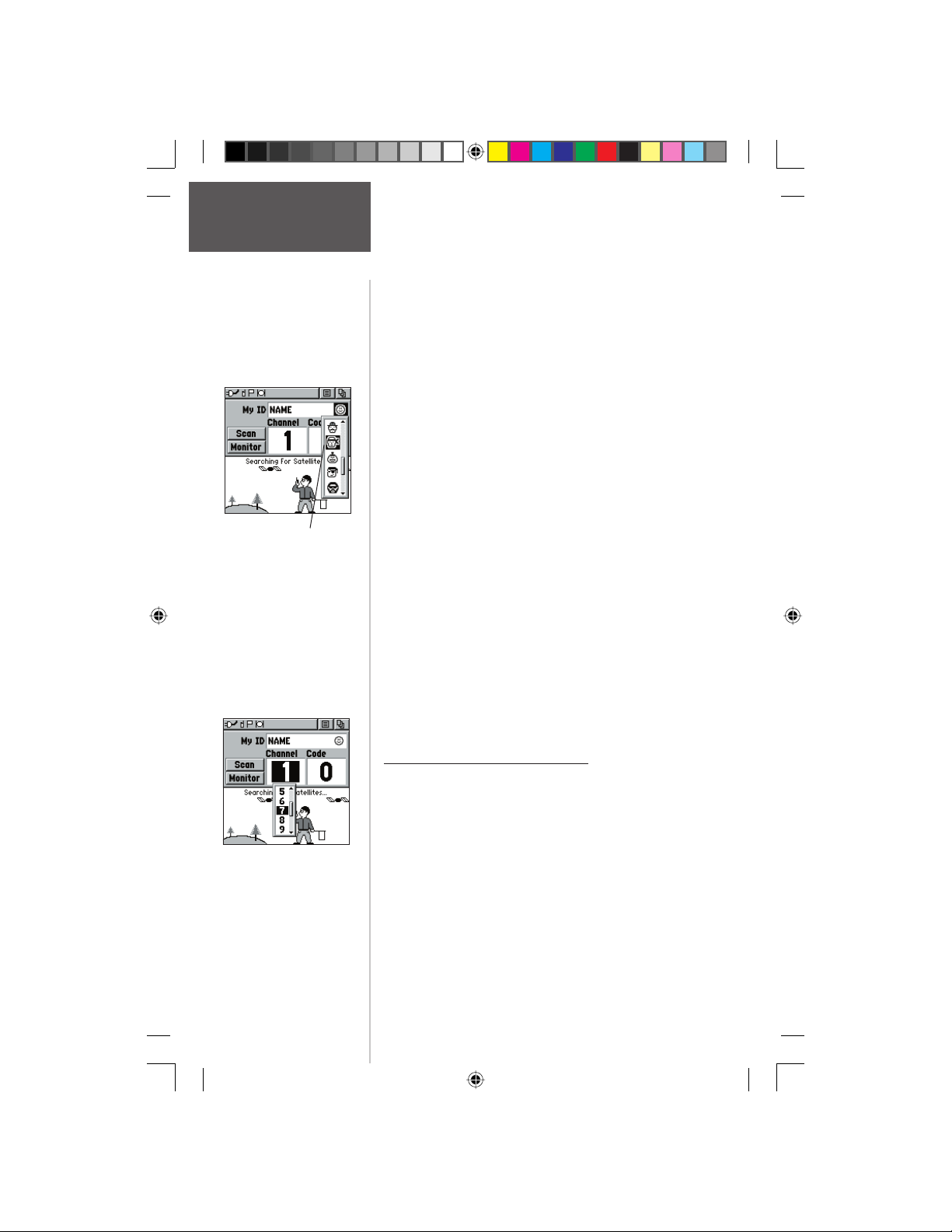
My ID and Symbol Fields - Overview
The ‘My ID’ fi eld allows you to enter a name and
symbol that will appear on other Rino units as you communicate with them. You may enter a name using up
to a combination of 10 letters, numbers or spaces. The
Symbol fi eld allows you to choose a face icon from a list
to further personalize your ID.
To enter a name:
1. Using the CLICK STICK, highlight the ‘My ID’
190-00284-00_Prelim_FCC.indd 3 9/18/2003, 3:50:47 PM
Preliminary
Symbol
fi eld and then press the CLICK STICK key IN.
This will activate the fi eld and display the keyboard.
3
Page 14
Radio Page
My ID /
Channels & Codes
Changing the user symbol
2. Move the CLICK STICK Up, Down, Left or Right
to highlight the ‘Clear’ fi eld, then press IN on the
CLICK STICK to clear the default ‘Name’ ID.
3. To enter a new ID, press the
Down, Left or Right to move the cursor to the desired
letter, number or a space, then press IN on the
CLICK STICK Up,
CLICK STICK to select that highlighted character.
You may enter up to 10 characters for your ID.
You will also see a highlight cursor in the ‘My ID’
fi eld showing your current entry position in that fi eld.
Choosing ‘Back’ will delete the character to the left
of the cursor. Use the left or right arrow symbols to
move the highlight in the ID fi eld.
4. When you have entered your new ID, use the
CLICK
STICK to highlight ‘OK’ and then press
IN on the CLICK STICK.
Changing the user symbol:
1. Using the CLICK STICK, highlight the face symbol
to the right of the ‘My ID’ fi eld and then press the
CLICK STICK key IN. This will show a list of
available face icons.
2. Move the
through the selections. Since not all the selections
can fi t in the window, you will see a slider bar on the
right side indicating your current position in the list.
3. Once you have highlighted the desired icon, press IN
on the
CLICK STICK Up or Down to scroll
CLICK STICK.
Channel and Code - Overview
Preliminary
Select from FRS channels
1-14 or GMRS 15-22.
4
190-00284-00_Prelim_FCC.indd 4 9/18/2003, 3:50:47 PM
The Rino has a total of 22 channels and 38 squelch
codes to select from using the ‘Channel’ and ‘Code’ fi elds.
Channels 1-14 are for FRS and 15-22 are for GMRS
(disabled by default). To communicate with other Rino
and FRS/GMRS users, you must be on the same Channel
and Code. Garmin Rino units will work with 3rd party
FRS/GMRS radios, provided the other radios use standard
FRS/GMRS frequencies. A chart of the Rino frequencies
may be found in Appendix H.
Squelch codes allow you to hear calls from only specifi c
persons. Thirty-eight Squelch Codes (called Continuous
Tone Controlled Squelch System or CTCSS) allows your
Rino to ignore unwanted calls from other persons who are
Page 15
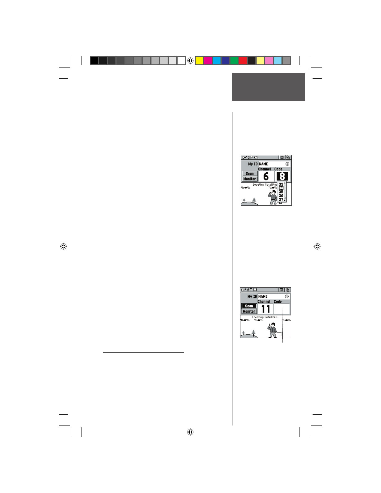
using the same channel. Simply select the same squelch
code (number) as selected by the other person(s) you
desire to communicate with. NOTE: Squelch codes do
Channels & Codes
not cause your conversation to be private. They only
allow you to fi lter out other users on the same channel, so you only hear the radios you want to. Squelch
Codes are not a scrambling system! Setting the code to 0
(squelch code off) will allow you to hear all activity on the
selected channel, but you must be set to the same code
as the other person(s) to transmit back. See Appendix H
for a table listing all of the 38 Squelch Codes and their
frequencies.
As you change the main channels, the Rino will
remember the last channel/squelch code combination
that you were using. For example, you may set the unit
to Channel 5, squelch code 21, then change the main
channel to 8 and that code to 2. If you change the channel back to 5, the squelch code will change back to its
previous setting of 21.
See Appendix A for more information on FRS/GMRS
and its operational aspects.
To change the Channel and/or Code:
1. Using the CLICK STICK, highlight the ‘Channel’
or ‘Code’ fi eld and then press the CLICK STICK
key IN. This will show a list of available channels/
codes.
2. Move the
through the selections. Since not all the selections
can fi t in the window, you will see a slider bar on
the right side indicating your current position in the
list.
3. Once you have highlighted the desired selection,
press IN on the
CLICK STICK Up or Down to scroll
Preliminary
CLICK STICK.
Scan and Monitor - Overview
The ‘Scan’ option allows you to scan through the
available channels for voice activity. As the unit scans and
receives a signal (or if you transmit), it will stop on that
channel/code for a few seconds, then continue scanning. You may also use the Set Scanlist option to pick
which channels/codes to scan. Since it can take time to
Radio Page
/ Scan & Monitor
Choose from 38 squelch
codes. Setting the unit
to zero will allow you to
hear all transmissions
on that channel, but you
must be on the same code
to radio back.
The Code fi eld will go
blank when the unit is
scanning channels.
5
190-00284-00_Prelim_FCC.indd 5 9/18/2003, 3:50:48 PM
Page 16
Radio Page
Scan & Monitor
The Code fi eld will go
blank when you monitor
a channel.
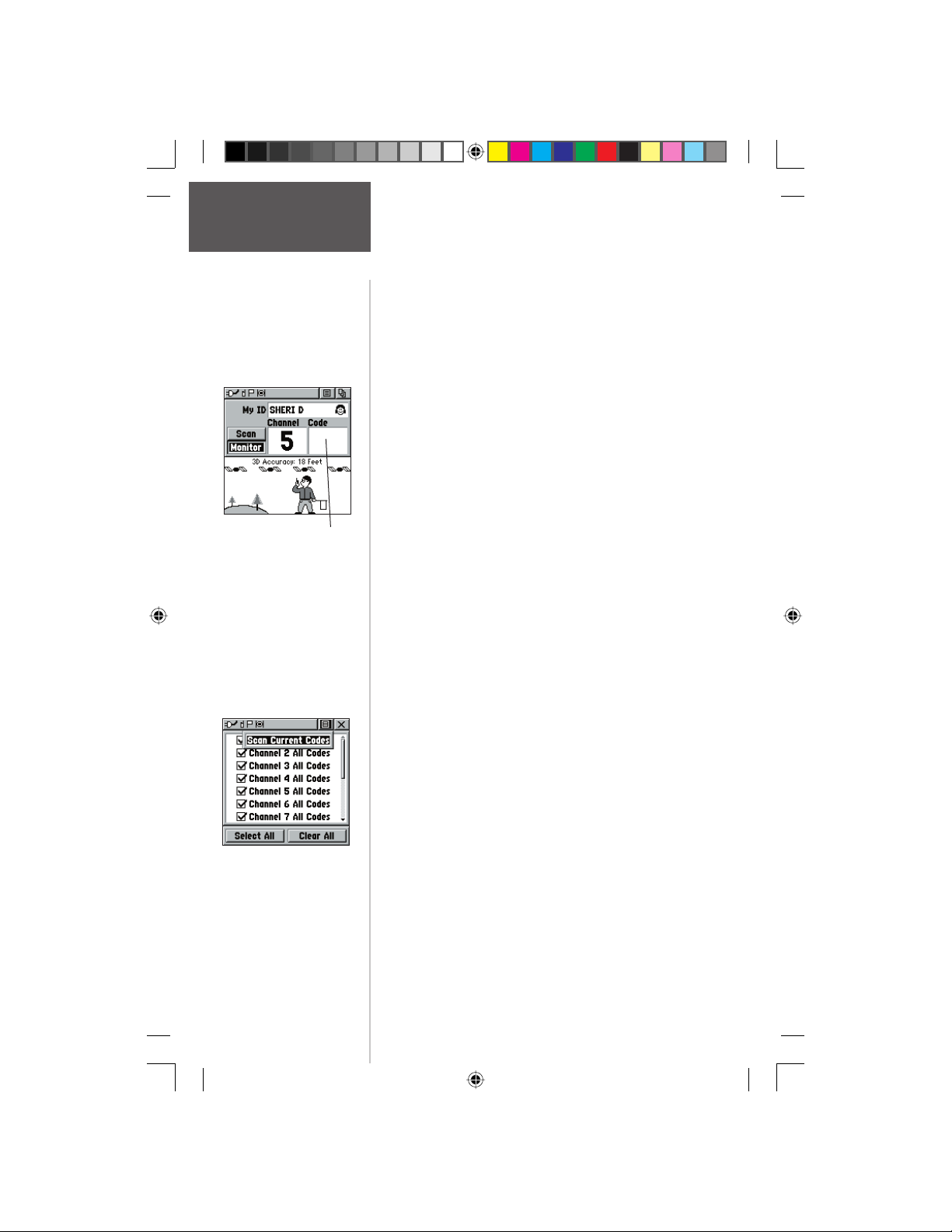
scan through the all the channels, selecting only specifi c
channels/codes will decrease the scan time. Decreasing scan
time will help prevent the chances of missing a transmission. The Scanlist also has Option Menu choices to ‘Scan
Current Codes’ or ‘Scan All Codes’. Choosing ‘Scan Current
Codes’ will scan only the Channel and Code combination
in memory
The ‘Monitor’ option lets you listen to a single channel
for any activity, including static and weak voice signals.
The Rino series will automatically squelch a frequency to
fi lter out unwanted noise. Using the Monitor option will
temporarily turn off the automatic squelch allowing you
to hear the open channel. If you see a broken transmission
symbol (see pg. 9), you may be receiving a signal too weak
to trigger the unit’s squelch. You might choose this option
if a signal is getting out of range or weak.
To Scan or Monitor a channel(s):
1. Using the CLICK STICK, highlight the ‘Scan’
or ‘Monitor’ button and then press the CLICK
STICK
key IN. ‘Scan’ will start searching through the
available channels. ‘Monitor’ will open the channel
in order to listen to any radio transmissions on that
channel.
2. To stop using either option, highlight the button with
the
CLICK STICK and press IN.
To Setup a Scanlist:
1. Using the CLICK STICK, highlight the Options
Menu on-screen button and press IN. Highlight
Preliminary
6
190-00284-00_Prelim_FCC.indd 6 9/18/2003, 3:50:49 PM
‘Setup Scanlist’ and press IN on the
STICK.
2. To add/remove a channel from the list, highlight
the channel and press IN on the CLICK STICK to
add/remove the check mark in from of the name.
Only channels that are checked will be scanned.
3. To Select/Clear All channels, highlight either the
‘Select All’ or ‘Clear All’ buttons and press IN on the
CLICK STICK.
4. To ‘Scan All Codes’ or ‘Scan Current Codes’, highlight
the Options Menu and press IN on the CLICK STICK.
Choose the desired setting and press IN on the
CLICK STICK.
CLICK
Page 17
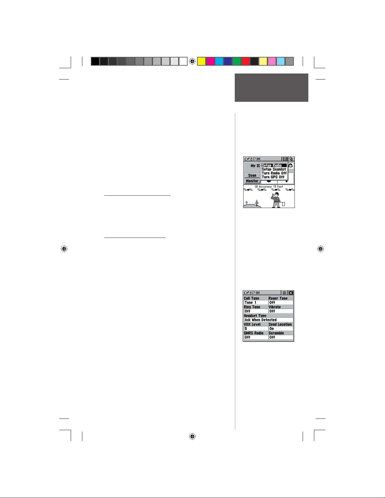
The Radio Page Options Menu provides the following:
Setup Radio, Setup Scanlist, Turn Radio Off/On and
Turn GPS Off/On.
To access the page Options Menu:
1. Highlight the Option Menu on-screen button at the
top of the display screen and then press IN on the
CLICK STICK to open the menu.
2. Highlight the desired option on the menu and then
press IN on the CLICK STICK to activate the option.
3. To close without making a selection, move the
CLICK STICK to the right.
Setup Radio - Overview
The ‘Setup Radio’ option displays the Radio Setup
Page. This page determines how the radio will function,
changes audible alerts and enables you to adjust the radio
operation to your needs.
Setup Radio - Options
The following options are available:
Call Tone - When the CALL button is pressed, an attention tone is transmitted. This option allows you to choose
from one of ten tones.
Roger Tone - When the TALK key is released, a tone is
sent to signify the end of the transmission. This option
allows you to choose from one of four tones, or set the
tone to ‘Off’.
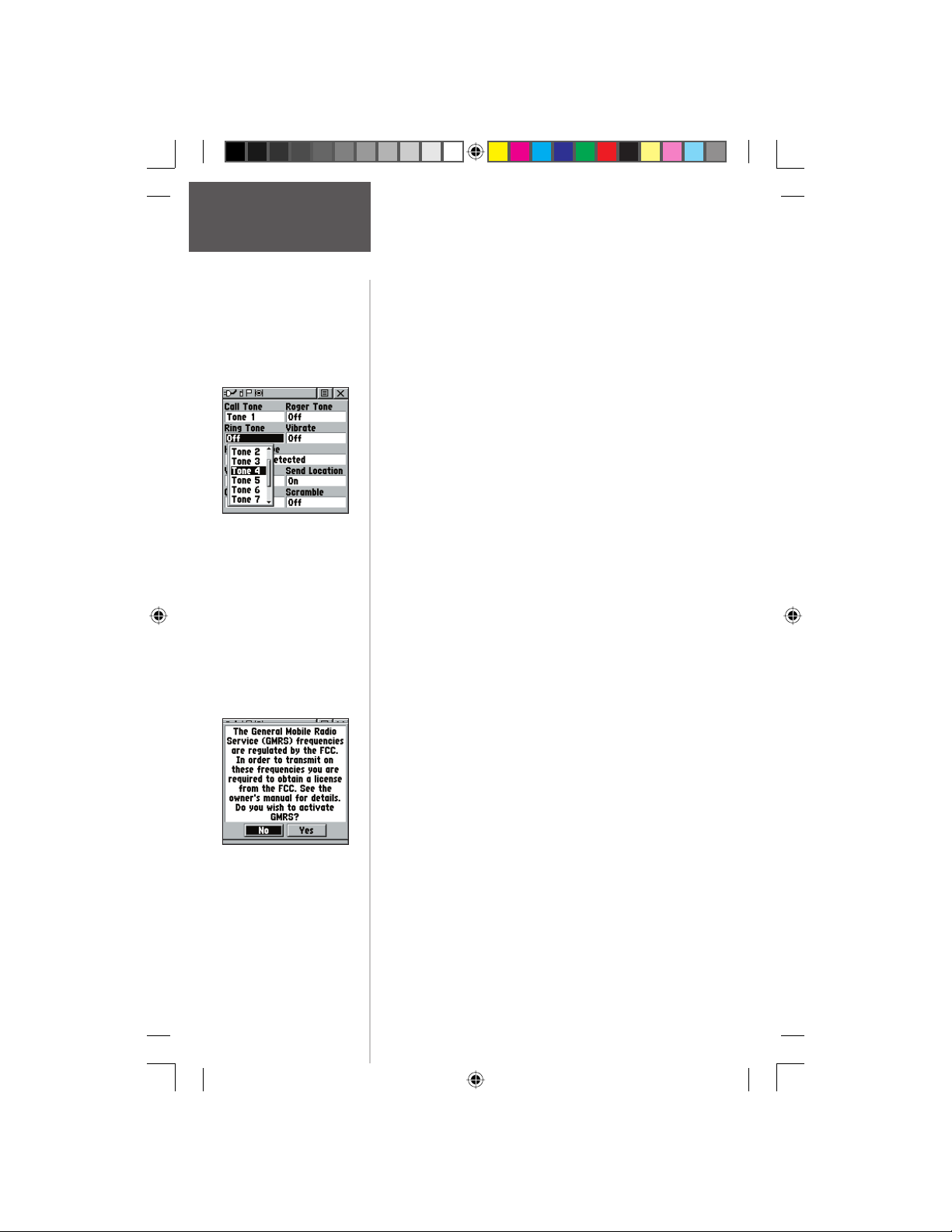
Ring Tone - When an incoming transmission is received,
an attention tone will sound. This option allows you to
choose from one of ten codes, or set the tone to Off. The
Ring tone will not sound again until there has been 45
seconds of radio inactivity.
Vibrate - Choose from ‘On’ or ‘Off’ to have the unit
vibrate when an incoming transmission is received. Once
received, the unit will not vibrate again until there has
been 45 seconds of radio inactivity.
Headset Type - Allows you to choose which accessory
headset or microphone you are using with the unit, or
have the unit automatically detect the type. If using more
than one type of headset or microphone, you will need
Preliminary
(Push To Talk) button, this
must be pressed in order for
the unit to detect the headset.
Radio Page
Setup Radio
Radio Page Options Menu
If the headset has a PTT
Radio Setup Page
7
190-00284-00_Prelim_FCC.indd 7 9/18/2003, 3:50:50 PM
Page 18
Radio Page
Setup Radio
Selecting a Ring Tone.
Tone will sound when you
press IN to accept it.
to set the unit to ‘Ask When Detected’ before changing
accessories.
VOX Level - Controls the sensitivity level of any Voice
Operated Transmission (VOX) accessory. VOX accessories
allow you to use the unit hands-free. A lower VOX setting
is recommended for quiet environments while a higher
VOX setting should be used in noisy environments.
Setting the VOX level to 5 is recommended for most
environments, but it may be necessary to adjust the level
to achieve the desired voice trigger level. You will hear
yourself talking in the headset when transmitting successfully using VOX.
Send Location - This option enables/disables the peerto-peer positioning feature. See page 11 for more on this
feature.
GMRS Radio - Use this option to turn On/Off GMRS
channels 15-22. Peer-to-peer transmissions are not available on GMRS channels. See page 2 for more information
on using GMRS channels.
Scramble - This feature adds a level of security to your
conversations with other Rino 130 users only. When On,
the voice transmission will sound garbled to other nonscrambled Rinos, as well as other 3rd party radios. When
set to On, in order for peer-to-peer and Send Location
(see pg. 11) features to work, the receiving radio must
also have Scramble enabled.
To use Setup Radio options:
1. Select ‘Setup Radio’ from the Options Menu and
Preliminary
You must obtain a license
to operate on GMRS
channels 15-22.
8
190-00284-00_Prelim_FCC.indd 8 9/18/2003, 3:50:50 PM
then press IN on the CLICK STICK to display the
Map Setup Page.
2. Highlight an option on the page and press IN on
the CLICK STICK to display the options list for that
feature.
3. Use the CLICK STICK to highlight the desired
selection and then press it IN to activate.
4. Press the PAGE button or the on-screen ‘X’ button
to return to the Radio Page.
Page 19
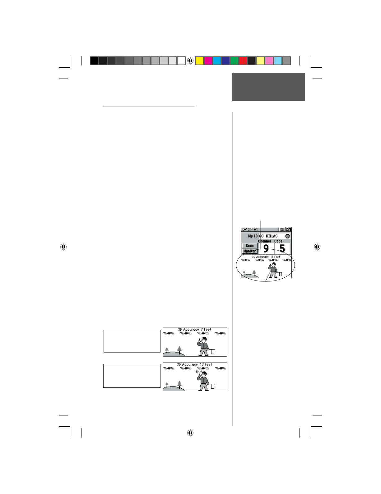
Informational Picture - Overview
The Informational Picture on the bottom half of screen
features Garmin’s Mr. Mark Waypoint to show current
GPS & radio status and radio actions. As you operate the
unit, the graphics will change depending on what actions
you are taking or the unit settings.
Four satellites are shown on at the top of the picture
along with descriptive text to indicate GPS reception
status. As the unit collects satellite information, the satellite symbols will fl ash alternately until all four are steady
indicating a 3D position fi x. The more satellites that are
steady, the better your position fi x.
As radio signals come in, signal wave symbols will
display to the left of Mark Waypoint. Fragmented (or
broken) signal symbols are shown to indicate activity on
that channel. Audio remains muted because the incoming
signal does not match the squelch code your unit is set to.
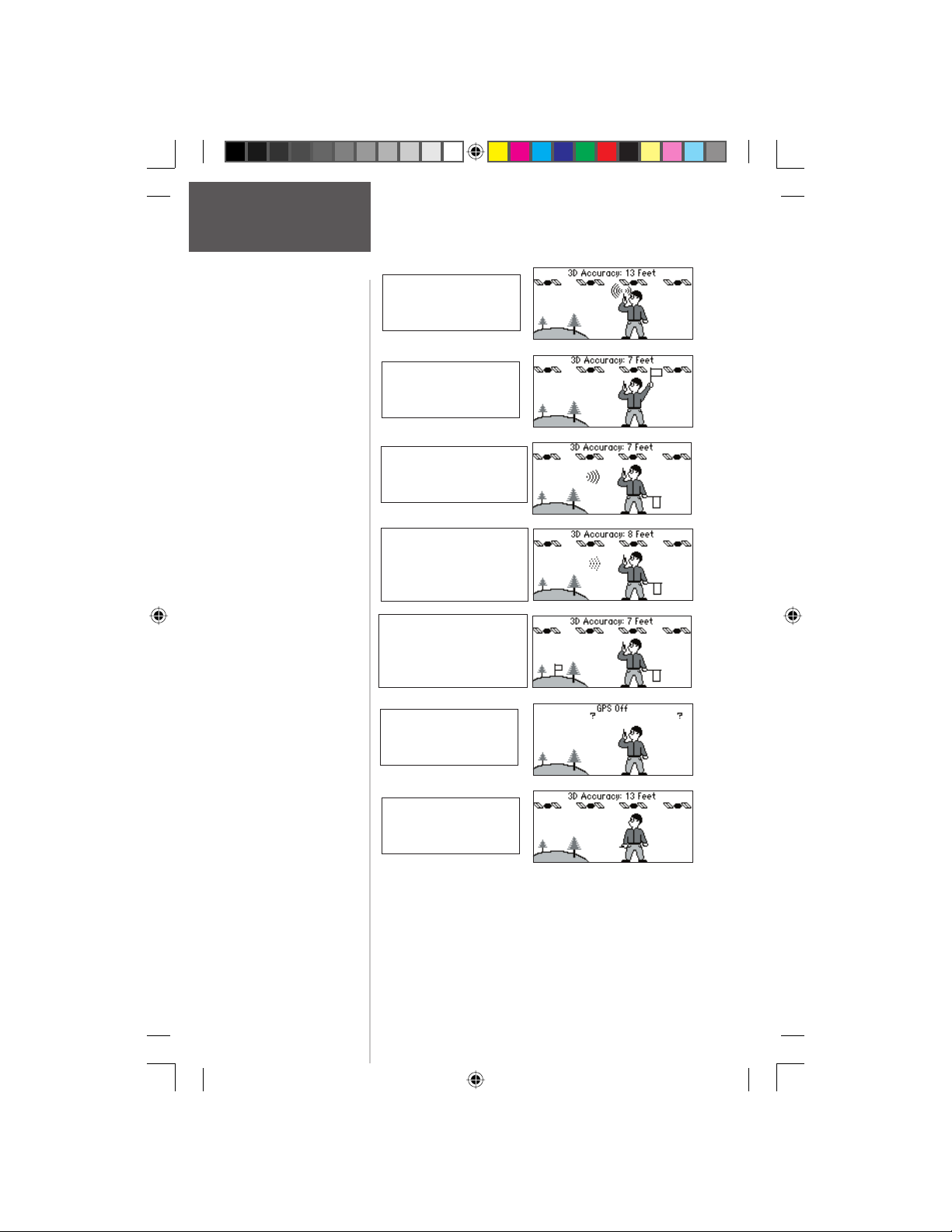
The Mark Waypoint fi gure will display several different icons, depending on what you are doing. A radio
in Mark’s hand indicates the radio is ready to use. A fl ag
in his other hand means the unit is ready to transmit its
position (GPS must be On to use this feature.) As you
transmit, you will see radio waves around Mark’s radio.
When your peer-to-peer transmission is sent, Mark will
raise the fl ag in his hand. As positions are received, a fl ag
will briefl y appear on top of the hill to the left.
See the following illustrations for more information:
Radio Page
Informational
Picture
Informational Picture
Mark Waypoint
Preliminary
GPS and Radio On;
Ready to transmit Position
GPS and Radio On;
Ready to transmit Position;
Transmitting on FRS
190-00284-00_Prelim_FCC.indd 9 9/18/2003, 3:50:51 PM
9
Page 20
Radio Page
Informational
Picture
GPS and Radio On;
Position not ready;
Transmitting on GMRS
GPS and Radio On;
Position transmitted
GPS and Radio On;
Ready to transmit Position;
Receiving transmission
GPS and Radio On;
Ready to transmit Position;
Activity on channel that
does not match code.
GPS and Radio On;
Ready to transmit Position;
Position received from
other Rino user
GPS Off; Radio On;
Position sending not
available
Preliminary
GPS On and Radio Off;
GPS operation only
10
190-00284-00_Prelim_FCC.indd 10 9/18/2003, 3:50:52 PM
Page 21
Peer-to-Peer - Overview
The Rino’s most unique feature is being able to send
it’s location to another Rino, this is called Peer-to-Peer positioning. With peer-to-peer enabled (see pg. 8) and you
have a GPS position (see pg. 48), whenever you press and
release either the CALL key or the TALK key, the Rino
will automatically send out its location. This information
will be available to all other Rino users that are monitoring the same channel and code. This feature allows you to
track the movement of other Rino users and even navigate
to their location. Locations may only be sent once
every 10 seconds, due to FCC restrictions.
To transmit your location to other Rino
users:
1. With ‘Send Location’ enabled (see pg. 8), press and
release either the TALK or CALL buttons. You will
see a fl ag on the top Status Bar or in Mark’s hand
when the unit is ready to transmit its position.
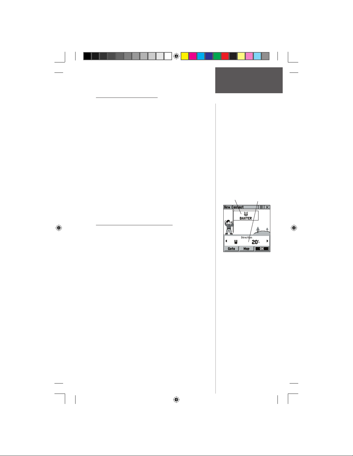
New Contact Page - Overview
The fi rst time that a signal is received from another
Rino user, a ‘New Contact’ page will be displayed. From
the New Contact page you can show their location on
your map, ‘Goto’ their location, or select ‘OK’ to add
them to your contact list. The Rino can manage up to 50
contacts at any time. Each time that you receive a signal
from a contact, your map will be updated showing their
new position and a Track Log of their movement will
be created and shown on your map (see pg. 45). After a
contact has been established, a “<contact name> Updated”
message will briefl y appear at the bottom of your display
each time the contact updates. You may also review each
contact’s information such as Direction, Elevation, Timestamp, Location and enter Notes up to 30 characters.
All contacts are listed on a Contact List Page and also
displayed in the Contact Bar on the Map Page (see pg.
14). Contacts behave like and count towards the 500
maximum waypoint total.
Preliminary
Peer-to-Peer /
Name &
Radio Page
Contacts
Symbol
New Contact Page
Information
Contact
Field
190-00284-00_Prelim_FCC.indd 11 9/18/2003, 3:50:53 PM
11
Page 22
Radio Page
Contacts
Move LEFT or RIGHT on
the CLICK STICK to view
different contact data.
Contact Bar
Preliminary
Contacts will also show on
the Map Page. Highlight
the contact and the map
will center on their last
position.
To accept a new contact:
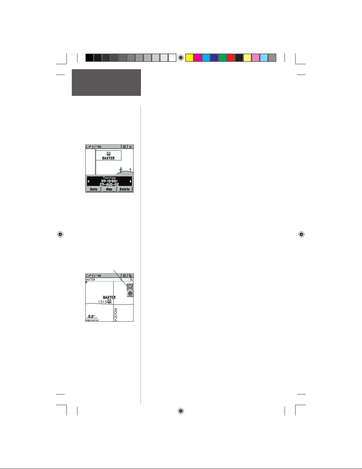
1. When a new contact is received, the New Contact
page will appear. Highlight ‘OK’ and press IN on the
CLICK STICK. If you do not OK the contact, it will
not be saved.
To review a contact and contact details:
1. From the Map Page, highlight the desired contact of
the Contact Bar and press IN on the CLICK STICK.
As you highlight the contacts on the Contact Bar,
the Map page will center the map on that contact
and display its name, direction and distance near
the top of the screen.
or
2. Press the CLICK STICK IN and hold it until the
Shortcuts Menu is displayed.
3. Highlight ‘Find ‘N Go’ and press the CLICK STICK
IN.
4. Highlight ‘Contacts’ and press the CLICK STICK IN.
5. From the Contacts List, select the desired contact
and press the CLICK STICK IN.
6. If the contact did not have a GPS location on the
last transmission, a ? mark will appear below the
fl ag. To view the contact details, highlight the details
fi eld and press LEFT or RIGHT on the CLICK STICK to
change to the next data fi eld.
To change contact details:
1. The Elevation, Position and Note fi elds may all
be manually edited. Select the desired fi eld and
press IN on the CLICK STICK. For Notes, highlight
‘Edit’ and press IN to start entering data, up to 30
characters. For other fi elds, highlight the fi eld and
press IN on the CLICK STICK to start changing the
data. Highlight ‘OK’ and press IN when done.
To view a contact on the Map Page:
1. From the Contact Review Page, highlight ‘Map’
and press IN on the CLICK STICK. Press PAGE when
done to return to the Contact Review Page.
12
190-00284-00_Prelim_FCC.indd 12 9/18/2003, 3:50:53 PM
Page 23
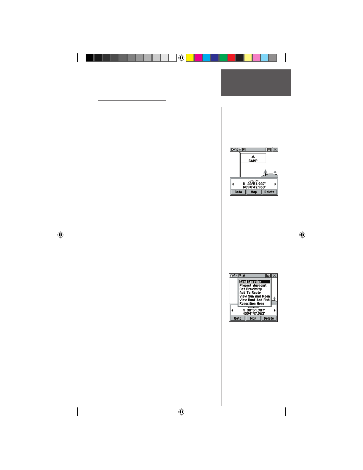
Send Location - Overview
Another feature is the ability to send a specifi c location
to other Rino users. This can come in handy if you are
trying to round-up the group, or just want to meet at a
specifi c location. You may send any point found from
the Find ‘N Go menu. If the unit needs to wait until 10
seconds have elapsed since the last position transmission,
a “Waiting to send location...” message will appear until
the unit is able to transmit. If a location is sent more than
once, a number will automatically be added to the end of
the name (CAMP, CAMP 1, CAMP 2, etc.).
To send a location:
1. Press the CLICK STICK IN and hold it until the
Shortcuts Menu is displayed.
2. Highlight “‘Find ‘N’ Go’” and press the CLICK
STICK IN.
3. Highlight the desired category and press the CLICK
STICK IN. ( For the Contacts List, select the desired
contact and press the CLICK STICK IN.)
4. Depending on which category you select, highlight
the desired item and press IN on the CLICK STICK to
display the Information page for that item.
5. From the Information Page, highlight the Options
Menu in the upper right and press IN on the CLICK
STICK.
6. Highlight ‘Send Location’ and press IN again. The
unit will now send the point to the other Rino users
on your channel/code. If using the Scramble feature,
receiving radios must also have Scramble enabled.
Preliminary
Radio Page
Send Location
To send a location, high-
light the Options Menu
from the Waypoint Review
Page and press IN.
Choose ‘Send Location’
and press IN.
190-00284-00_Prelim_FCC.indd 13 9/18/2003, 3:50:54 PM
13
Page 24
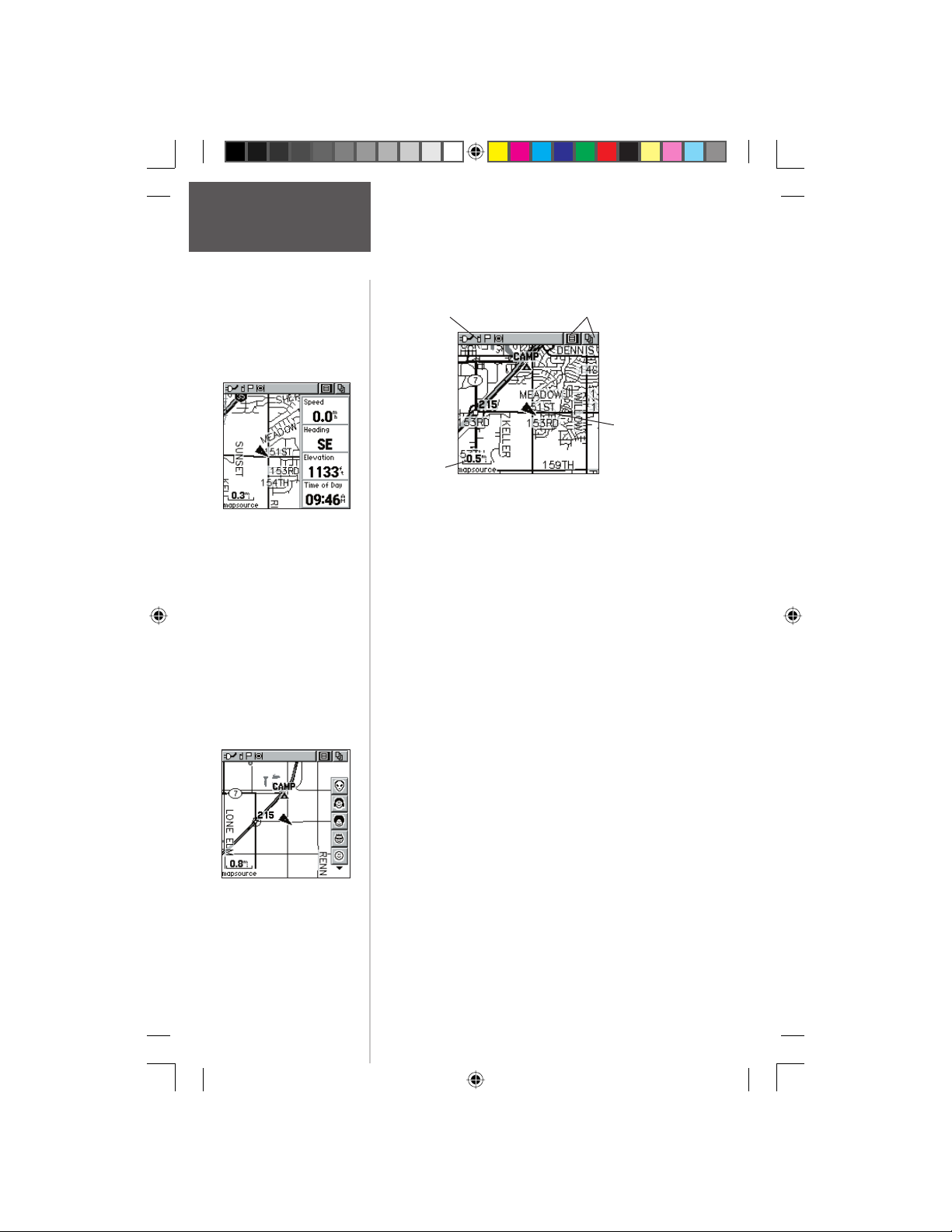
Map Page
Main Page
Map Page with Data
Fields
Preliminary
Status Bar
Map Scale
The Map Page displays your present position and
direction of movement using a triangular ‘Position Icon’
that is centered on the map. As you travel the map display
leaves a “trail” (track log) of your movements.
The map also displays geographic details such as
rivers, lakes, highways, and towns. The map shown
above displays a higher level of detail than the basemap
provided with the unit (i.e. residential streets, parks, etc.),
because Garmin MapSource data has been downloaded to
the unit using a CD-ROM mapping program.
On the right side of the Map Page, you can choose to
show either the Contact Bar (see also pg. 12), Data Fields
or show the Map Only. As you highlight the contacts on
the Contact Bar, the Map page will center the map on that
contact and display its name, direction and distance near
the top of the screen.
Option Menu & Main
Page Menu Buttons
Position Icon
To view a Contact from the Map Page:
1. Highlight the Contact Icon using the CLICK STICK.
Press IN if you want to view the details of the
Map Page with
Contact Bar
14
190-00284-00_Prelim_FCC.indd 14 9/18/2003, 3:50:55 PM
Contact.
2. Press to the LEFT or RIGHT on the CLICK STICK in
order to recenter the map on your current position.
Page 25
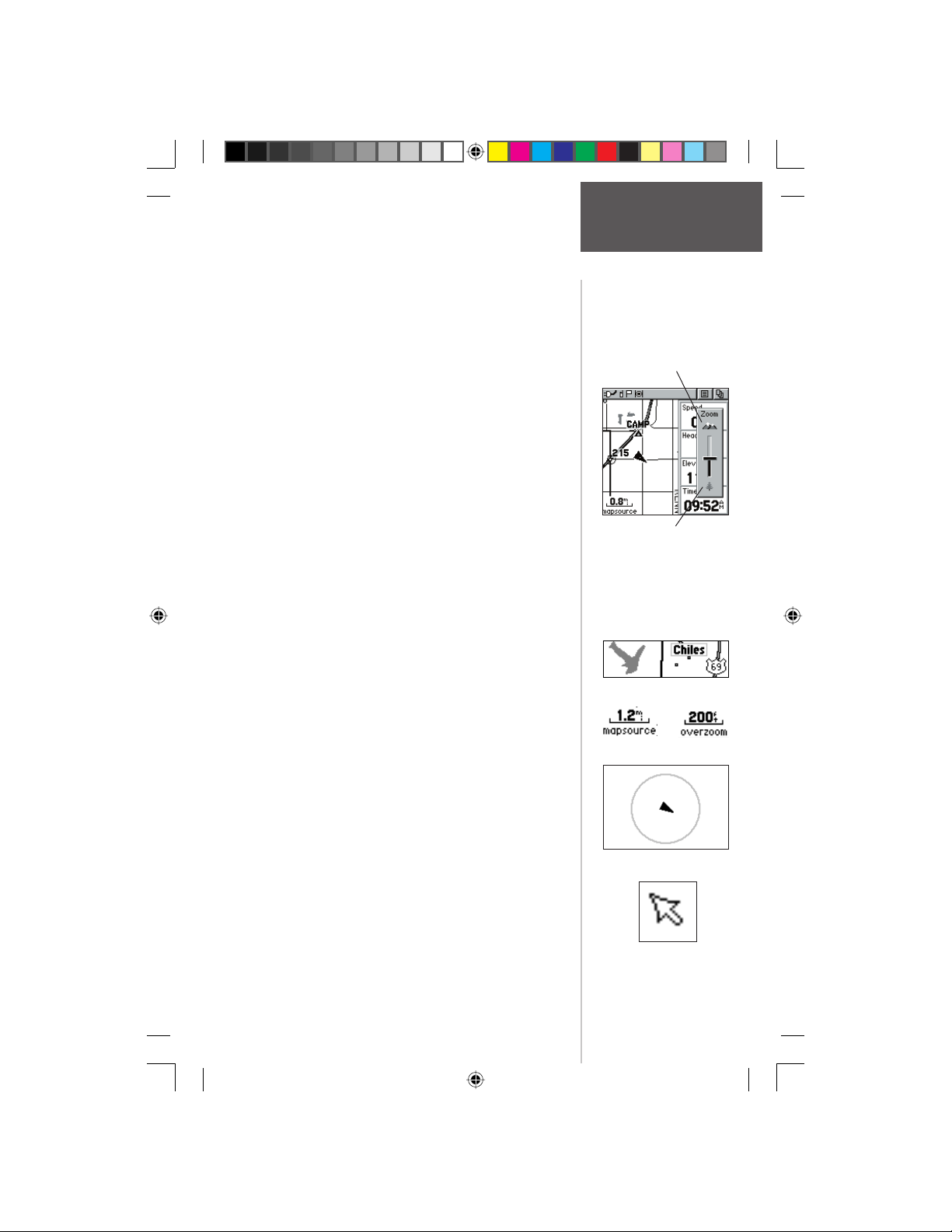
To allow you to view the map from different perspectives, the scale can be changed from 20 feet to 500 miles.
The CLICK STICK and Z (Zoom) button on the front
right of the unit allow you to zoom in or out on the map.
Pressing the Z (Zoom) button from any page (other than
the Map Page) will automatically take you to the Map
Page. A lower zoom scale displays less area but more map
detail, while a higher zoom scale shows you a larger area
with less map detail.
To change scales on the Map Page:
1. Use the CLICK STICK and Z (Zoom) button to
change the map scale in order to show more map
area with less detail or less map area with more
detail.
2. Press and hold UP or DOWN on the CLICK STICK to
zoom the map scale rapidly.
Press DOWN to Zoom In
The map scale in the lower left hand side of the
display is shown in units of measurement selected in the
‘Units’ fi eld of the Unit Setup Page (not to be confused
with the Map Setup Page). If you zoom in so far that the
resolution of the map data is exceeded and the appearance of the map is no longer accurate, the word, “overzoom” displays just below the map scale.
In many instances the map displays an ‘Accuracy
Circle’ surrounding the ‘Position Icon’. The Rino 130
uses both map resolution and GPS accuracy in defi ning
your location to a point within the circle. The smaller the
circle, the more accurate your location.
When using the ‘Pan Map’ feature, a small outline
arrow (Map Pointer) can be moved about the page to
Preliminary
highlight and identify map items or to scroll the map to
view areas not shown on the display screen.
Four optional Data fi elds on the right side of the page
can be programmed to provide a variety of travel and
navigation information.
More detailed map features as well as information
about those features can be downloaded to the unit from
a Garmin MapSource CD-ROM. When using MapSource
data, the word ‘mapsource’ displays below the map scale
whenever you zoom in to view map details.
Map Page
Main Page
Press UP to Zoom Out
Map Features
Map Scales
Accuracy Circle
Panning Arrow
(Map Pointer)
15
190-00284-00_Prelim_FCC.indd 15 9/18/2003, 3:50:55 PM
Page 26
Map Page
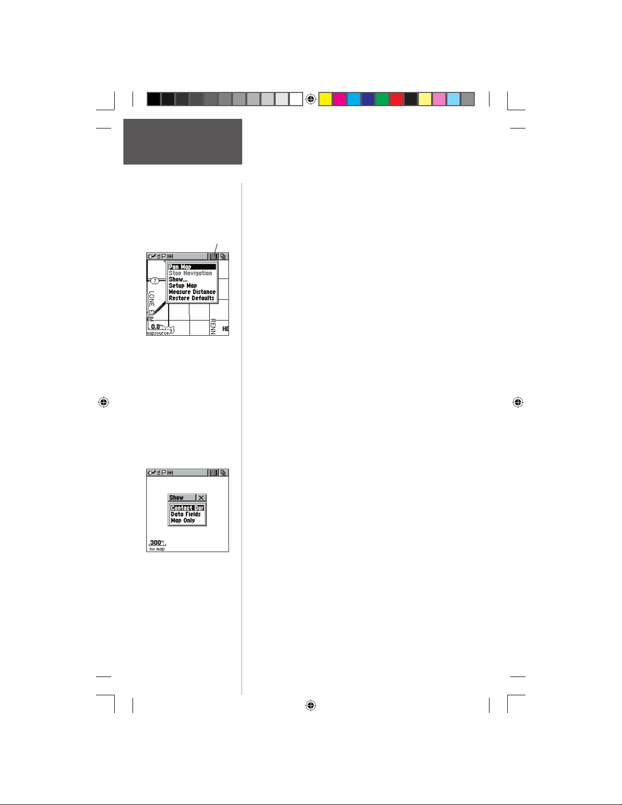
Options
On-screen Map Page
Options Menu button
Map Page Options Menu
with ‘Pan Map’ selected.
When no active navigation
is being used ‘Stop Naviga-
tion’ displays in gray..
Preliminary
Map Page options allow a variety of operating and
custom features for your Rino 130.
The Map Page options are:
Pan Map - Allows you to move the Panning Arrow
(Map Pointer) about on the map.
Stop Navigation - Stops navigating to a destination.
Show... - Allows you to choose to show either the
Contact Bar (see also pg. 12), four programmable
Data Fields or show the Map Only. As you highlight
the contacts on the Contact Bar, the Map page will
center the map on that contact and display its name,
direction and distance near the top of the screen.
Choosing either Contact Bar or Data Fields reduces
the map area.
Setup Map - Displays the Setup Map Pages, which allows you to tailor the map to your requirements such
as changing text size, map orientation, and map detail.
Measure Distance - Displays the distance from one
point on the map to another.
Restore Defaults - Returns the Map Page to the
original factory settings (defaults).
To select a map page option:
1. Highlight the Option Menu on-screen button at the
top of the display screen and then press IN on the
CLICK STICK to open the menu.
2. Highlight the desired option on the menu and then
press IN on the CLICK STICK to activate the option.
3. To close without making a selection, move the
CLICK STICK to the left or right.
The ‘Show..’ lets you
choose the layout of
the Map Page.
16
190-00284-00_Prelim_FCC.indd 16 9/18/2003, 3:50:56 PM
Page 27
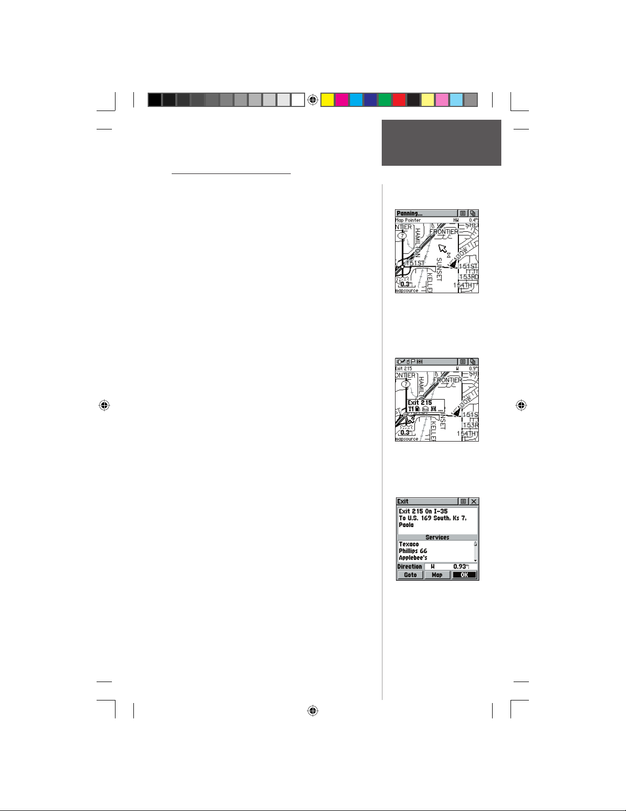
Using the Pan Map Option
The Map Page pan function allows you to display an
arrow used to point at and identify items on the map,
and to move the map in order to view areas beyond the
current viewing area on the display.
The map panning function is activated from the Options Menu on the Map Page. The CLICK STICK moves
the panning arrow (also referred to as the map pointer)
in the desired direction on the map page. If the arrow
moves to the edge of the map display, the map also moves
to reveal more area and a busy hourglass appears by the
cursor while the data is drawn on the screen.
Whenever the panning arrow is placed on a map item,
the name of that item is highlighted. This feature applies
to waypoints, roads, lakes, rivers...nearly everything that
is displayed.
Pressing the CLICK STICK marks the arrow location
or displays the map item information page. An Options
Menu allows you to: send the location of that item,
project a waypoint from it, save it as a waypoint, set a
proximity circle around it, add it to a route, or view the
sun and moon phase or view hunt and fi sh information
from it. On-screen buttons at the bottom of the page allow you to Goto the map item, display it on the map or to
select ‘OK’ and return to the Map Page.
When using the panning arrow, pressing and holding
IN on the CLICK STICK, then choosing ‘Find ‘N Go’
displays items with the panning arrow (map pointer) location used as a reference point for nearest items instead
of your current location. Press the PAGE button to return
to the Main Map Page.
Preliminary
Highlighted Map Item
Map Page
Options
Map Page with
Panning Arrow
To fi nd details about or Goto a map item:
1. Use the CLICK STICK to move the panning arrow
to the map item that you want to learn more about.
2. When the item’s name is highlighted, press IN the
CLICK STICK to display the Information Page.
3. Use the CLICK STICK to highlight and press the
‘Goto’ button on the page to navigate to the item.
190-00284-00_Prelim_FCC.indd 17 9/18/2003, 3:50:57 PM
Map Item
Information Page
17
Page 28
Map Page
Options
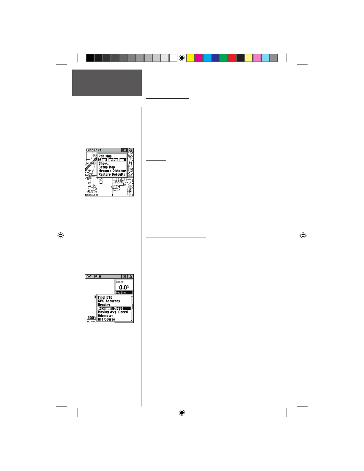
‘Stop Navigation’ Option
Preliminary
Changing Data Fields.
18
Stop Navigation
The ‘Stop Navigation’ option allows you to quit navigation
of a Goto, Route or Track in progress. When there is no active
navigation, the ‘Stop Navigation’ option is “grayed out” and is
non-functional.
To stop navigation:
1. Select ‘Stop Navigation’ and press IN on the
CLICK STICK.
Show...
The ‘Show...’ option allows you to view either navigation
data in a four fi eld window on the right side the page or the
Contact Bar. When ‘Map Only’ is chosen, more map area is
displayed.
To show Contact Bar, Data Fields or Map Only:
1. Select ‘Show..’ from the option list and then press IN on
the CLICK STICK.
2. Choose the desired option and press IN on the
CLICK STICK.
Data Field Instructions
When ‘Show... Data Fields’ is selected, four optional Data
Fields on the right side of the page can be programmed to
provide a variety of travel and navigation information. A list
of the choices can be found below. Not all data types will be
available on every page.
To program a data fi eld:
1. Use the CLICK STICK to highlight the data fi eld and
then press IN to display the list of data options.
2. Highlight the desired option and then press IN on the
CLICK STICK to change the data fi eld type.
Bearing
Course
Current Destination
Current Distance
Current ETA
Current ETE
Elevation
Final Destination
Final Distance
Final ETA
Final ETE
GPS Accuracy
Heading
Location (lat/lon)
Location (selected)
Maximum Speed
Moving Avg. Speed
Odometer
Off Course
Overall Avg. Speed
Pointer
Speed
Sunrise
Sunset
Time of Day
To Course
Trip Odometer
Trip Time - Moving
Trip Time - Stopped
Trip Time - Total
Turn
Velocity Made Good
Vertical Speed
190-00284-00_Prelim_FCC.indd 18 9/18/2003, 3:50:58 PM
Page 29
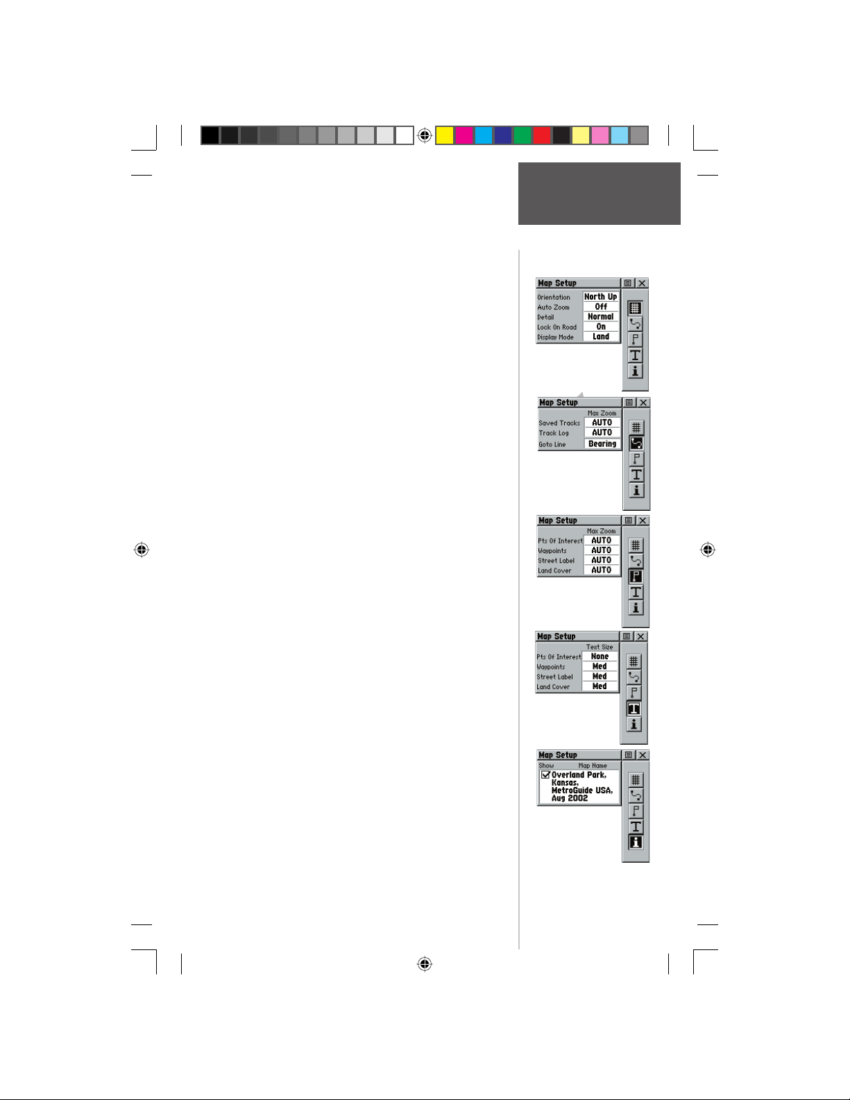
The ‘Setup Map’ option displays the fi ve Map Setup
Pages, each accessed by an on-screen button. A list of
options displays for the features listed. Scale options
indicate the zoom level at which Tracks, Tracks Logs, Map
Features, or Text Boxes display, allowing you to remove
map clutter and defi ne map features.
Map Page
Setup Options
Page - Orientation:
of the map display to the current track heading or to
a north heading.
Auto Zoom:
to display both your current location and the next
point to which you are navigating.
Detail:
how much map detail you see. This setting only
applies to a map feature set to ‘Auto’. Those features
which have a specified scale or are turned ‘Off’ are
unaffected by this setting.
Lock on Road:
Data is loaded; when ‘On’ the triangle icon locks to
the road that you are traveling.
Display Mode:
color while the other displays in a dark color.
Tracks - Saved Tracks and Track Log:
‘Auto’, or 20 ft.-500 miles, sets the maximum scale at
which the feature should appear on the screen. Some
types of data will display only to certain zoom scales.
Goto Line:
Map Features - Points of Interest, Waypoints, Street
Text - Points of Interest, Waypoints, Street Label, and
MapSource Info - Show, Check box;
Preliminary
Label, and Land Cover,
20 ft.-500 miles, sets the maximum scale at which
the feature should appear on the screen. Some types
of data will display only to certain zoom scales.
Land Cover,
‘Large’
determines if map data is used or not. Options Menu
allows you to choose to show all, show none or show
specific MapSource Data. See also page 66..
‘Track Up’ or ‘North Up’; fixes the top
On or Off;
Most, More, Normal, Less, or Least; controls
Bearing or Course.
Text sizes;
control the screen size of the name
automatically scales the map
On or Off; available only if MapSource
Land or Water; choice displays in light
Scale options;
Scale options;
‘None’, ‘Small’, ‘Medium’, or
‘Off’, ‘Auto’, or
check mark
‘Off’,
.
Page Setup
Tracks Setup
Map Features
Setup
Text Setup
Map Data
Setup
19
190-00284-00_Prelim_FCC.indd 19 9/18/2003, 3:50:59 PM
Page 30
Map Page
Setup Options
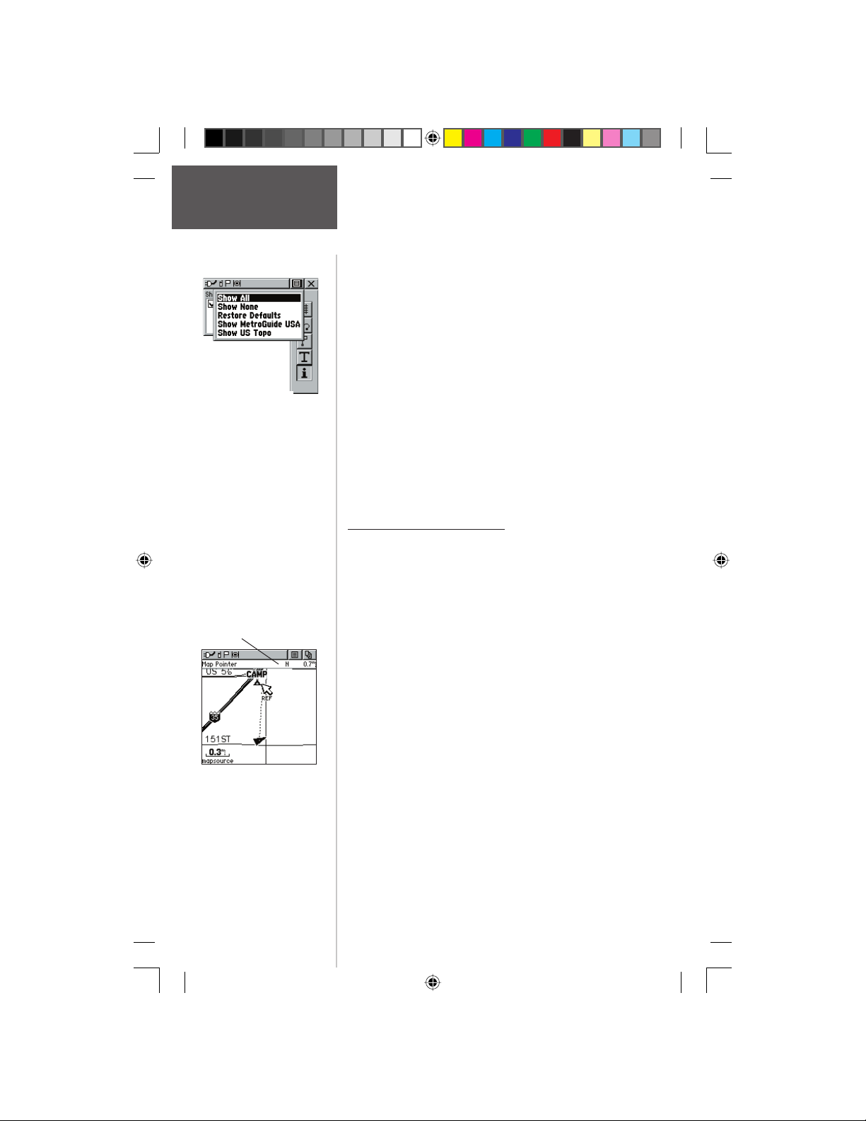
If you have more than one
type of MapSource data
loaded, you can quickly
choose to show one or the
other.
Map Pointer Field
Preliminary
Measuring distance.
To use Setup Map options:
1. Select ‘Setup Map’ from the Options Menu and then
press IN on the CLICK STICK to display the Map
Setup Page.
2. Press UP or DOWN on the CLICK STICK to
highlight the desired sub-page button, which will
display the options list for that sub-page to the left.
3. Press LEFT (Pressing RIGHT will return you to the
sub-page buttons), then UP or DOWN on the
CLICK STICK to highlight a feature on the list and
press IN on the CLICK STICK to display the options
list for that feature. Pressing RIGHT will return you
to the sub-page buttons.
4. Use the CLICK STICK to highlight the desired
option and then press it IN to activate.
5. Press the PAGE button or the on-screen ‘X’ button
to return to the Map Page.
Measure Distance option
To use the Measure Distance option:
1. Select ‘Measure Distance’ from the Options Menu
and then press IN on the CLICK STICK to display
the Panning Arrow. You will see ‘Ref’ under the
arrow.
2. Use the CLICK STICK to move about on the Map
Page until you reach the point to which you want
to measure. A new ‘Map Pointer’ fi eld displays
showing the location of the pointer and the
direction and distance from where you began the
measuring.
3. To begin measuring from a different point, press IN
on the CLICK STICK from the desired location.
4. To stop measuring, press the PAGE key .
20
190-00284-00_Prelim_FCC.indd 20 9/18/2003, 3:51:00 PM
Page 31
Navigation Page
The Main Page
Destination
(Waypoint) Name
Bearing Pointer
Compass Ring
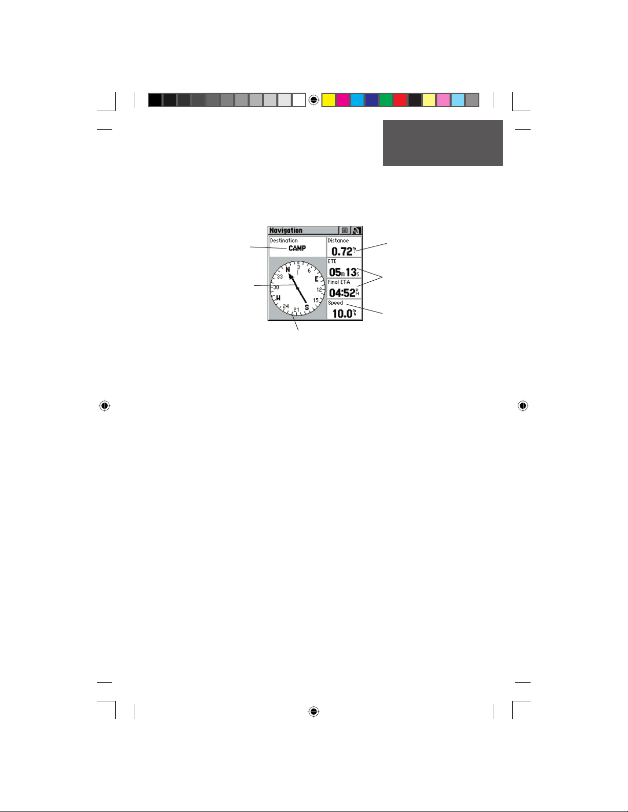
The Navigation Page provides active guidance with a rotating compass ring that
shows your course over ground (track) while you’re moving and a bearing pointer to
indicate the current direction to your destination (bearing) relative to the course over
ground.
The Compass Ring does not function as a magnetic compass when you are stationary. Although the bearing to a point will be correct, you must be moving in order for the
compass functions to work properly. When you are moving, the heading is controlled by
the GPS receiver.
The Data Field the top of the page, by default shows you the name of your destination. All fi ve Data Fields can be programmed to display a variety of navigation data.
The list of data fi eld choices may be found on page 18 and defi nitions may be found in
Appendix F.
While you are navigating a route, the pointer indicates the direction (a bent arrow)
of the turn to the next point in the route as well as the direction to the current point
when you get within 15 seconds ETA of the current point.
When you are not on an active Goto, Track or Route (in other words: not traveling
to a recorded destination), the window at the top of the page will be blank when ‘‘Destination’ is selected. The Compass Ring displays your heading while you are moving, but
the data fi elds to the right of the page will not display any destination related data, such
as Estimated Time of Arrival.
Preliminary
Straight Line Distance
to the Destination
Times to Destination
Selectable Data Fields
190-00284-00_Prelim_FCC.indd 21 9/18/2003, 3:51:00 PM
21
Page 32
Navigation Page
The Main Pages
CDI Scale
Navigation Page with
Course Pointer and
Course Deviation Indicator
(CDI) Scale active.
Preliminary
Navigation Page with
Bearing Pointer and
Big Compass..
Navigation Page Options
The options include:
Stop Navigation - Cancels navigation (“Grayed
out” or disabled unless you are navigating on a Goto,
Track, or Route.)
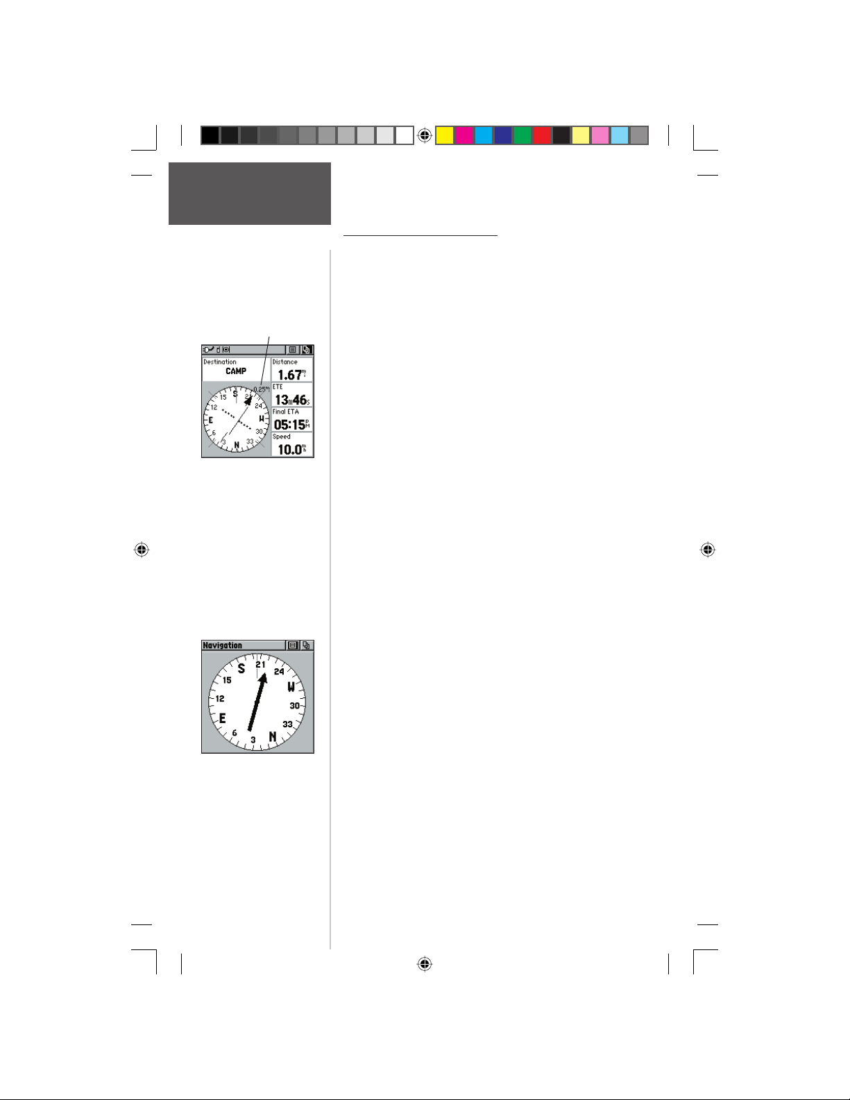
Bearing Pointer/Course Pointer - Toggles between
Bearing (always directed at destination) and Course
(distinctive with dots across center of compass, shows
amount of correction needed to be back on course.)
Change Scale - Only appears when Course
Pointer is selected. Use the CLICK STICK to
change the CDI scale. Scale value appears in
the upper right area of the compass.
Show Data Fields/Big Compass -
data fi elds on the right side of the display or removing
the data fi elds and showing a larger compass.
Restore Defaults - Returns options and data fi eld
choices to factory designations.
To the right of the page are four data fi elds (and one
on the top) that are user programmable with a choice of
different data options. See page 18 for details on changing
data fi elds.
The Bearing Pointer and Compass Ring work independently of the direction of your movement and the
direction to your destination. The Bearing Pointer always
points directly to the destination, no matter what your
current location might be.
For example: if the arrow is pointing straight up,
you are going directly to your destination. If it points
any direction other than up, turn and move towards
the direction the arrow is pointing until it points up
and then continue in that direction. If you are using the
‘Course Pointer’ option instead and you drift away from
the original line of travel to your destination, the Course
Deviation Indicator (CDI) provides graphic indication of
drift (right or left) and displays the distance off course.
toggles to display
22
190-00284-00_Prelim_FCC.indd 22 9/18/2003, 3:51:01 PM
Page 33
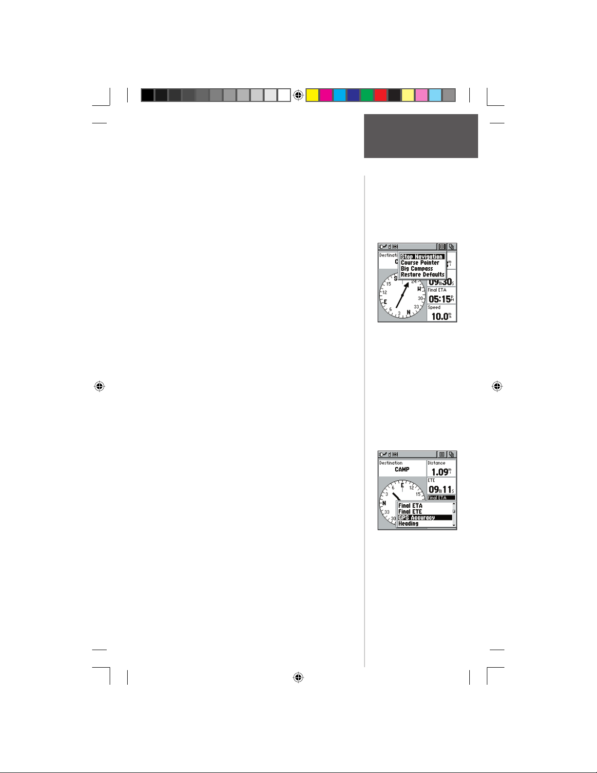
To Setup the Navigation Page:
1. With the Navigation Page displayed, use the
CLICK STICK to highlight the Options Menu button
at the top of the page. Then press it IN to display
the menu.
2. Use the CLICK STICK to highlight your selection
and then press IN to select it.
To stop navigating:
1. Highlight the on-screen Options Menu button at the
top of the Navigation or Map Page and press the
CLICK STICK.
2. Select ‘Stop Navigation’, then press the
CLICK STICK.
To change data fi elds:
1. Use the CLICK STICK to highlight the desired data
fi eld and then press it IN to display the list of data
options.
2. Select the desired option from the list and press IN
on the CLICK STICK.
The list of data fi eld choices may be found on page 18
and defi nitions may be found in Appendix F.
Navigation Page
The Main Pages
Navigation Page
Options Menu
Preliminary
Navigation Page
Changing Data Fields
190-00284-00_Prelim_FCC.indd 23 9/18/2003, 3:51:02 PM
23
Page 34
Trip Computer Page
Main Page
Trip Page shown with
Big Numbers
Preliminary
Selectable Data Fields
Trip Computer Page
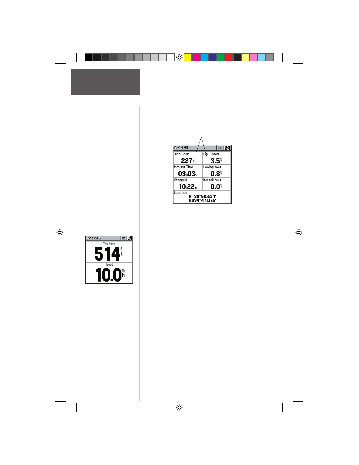
The Trip Computer Page default displays up to
seven different types of navigation data. Choosing ‘Big
Numbers’ will display 2 large data fi elds. Each data fi eld
is selectable and can contain one of many data information options.
By selecting the information options that you prefer
and arranging them in a desired order on the page, you
can customize the Trip Computer Page to meet your
navigation needs.
The Options Menu allows you to reset the Trip Computer data when you are ready to start a new trip, choose
between Big or Small Numbers and Restore Defaults.
24
190-00284-00_Prelim_FCC.indd 24 9/18/2003, 3:51:02 PM
Page 35
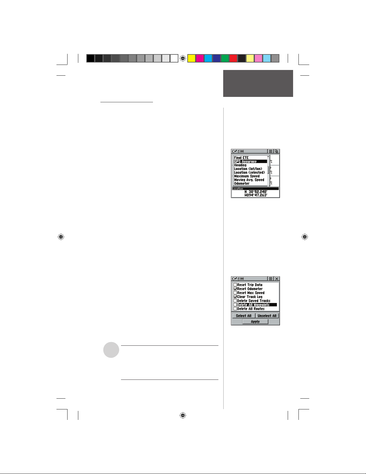
Trip Computer Page
The Trip Computer provides a variety of data fi elds
with read-outs of current information as you travel.
Seven small or two large fi elds display navigation
information and are user programmable. The default settings for these fi elds are shown in the illustration.
The list of data fi eld choices may be found on page 18
and defi nitions may be found in Appendix F.
The Option Menu for this page provides the following options: Reset, Big Numbers, and Restore
Defaults.
To program a data fi eld:
1. Use the CLICK STICK to highlight the desired data
fi eld and then press it IN to open the data fi eld
Options Menu.
2. Use the CLICK STICK to move Up or Down the
menu to highlight a desired data option.
3. Press IN on the CLICK STICK to select the option
and place it in the data fi eld.
To access the page Options Menu:
1. Use the CLICK STICK to highlight the Options
Menu on-screen button and press it IN to display
the Options Menu.
2. Highlight the desired option and then press IN on
the CLICK STICK to activate.
3. To activate individual ‘Reset’ options, highlight
the item on the list and then press IN on the
CLICK STICK to place or remove the check mark.
4. Once you check all the desired items to clear, reset,
,
Preliminary
or delete, highlight ‘Apply’ and press IN on the
CLICK STICK. You may also choose the ‘Select All’ or
‘Unselect All’ options accordingly.
NOTE: Use care when choosing the ‘Delete’
options, as all stored Tracks, Waypoints, and
Routes can be permanently deleted when resetting the Trip Computer. Once deleted, items
cannot be recovered.
Trip Computer Page
Options
Data Field Options Menu
Reset Options Menu.
Useful when starting a new
trip to clear old data.
25
190-00284-00_Prelim_FCC.indd 25 9/18/2003, 3:51:03 PM
Page 36
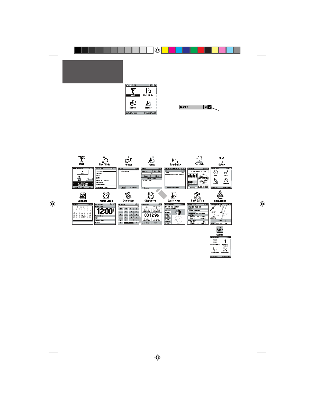
Main Menu Page
The Main Menu Page with
Main Page
To exit these pages, highlight the on-screen ‘X’
button and press IN on the CLICK STICK.
Time/Date.
The Main Menu provides you with a directory of the Rino’s advanced features. From
the Main Menu page you can mark and create new waypoints; fi nd map items such as
cities, interstate exits, addresses, points of interest, etc.; create routes; save tracks; setup
system operating features; access and use unit accessories or add/remove main pages
and adjust their ordering.
Main Menu Pages
Feature Icons
&
Page Sequence Setup
You may add, remove, or reorder any of the Main Pages, plus additional
pages. The default Main pages are Radio, Map, Navigation, Trip Computer,
and Main Menu. The Main Menu cannot be removed from the page sequence. If a page is
Preliminary
added to the Main Page Sequence, it will not appear in the Main Menu.
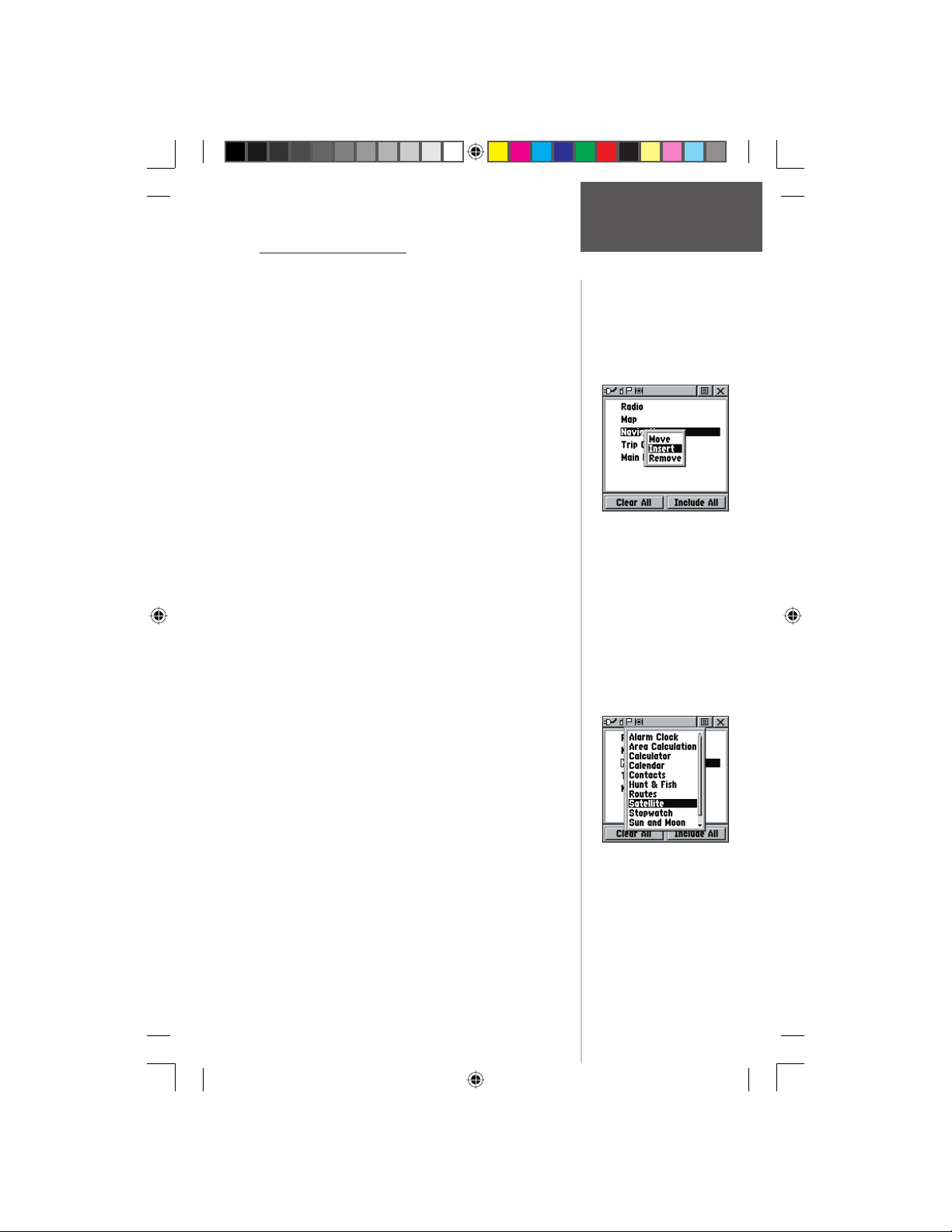
To move, insert or remove a Main Page:
1. From the Main Menu, highlight the Option Menu on-screen button and press the
CLICK STICK IN. Highlight ‘Page Sequence Setup’ and press IN.
2. To move a page in the order, highlight the page and press IN. Select ‘Move’, then
move UP or DOWN until the desired position is displayed and press IN.
3. To insert a new page, highlight the page you wish to insert it before and press IN.
Select ‘Insert’, then choose a page from the list and press IN on the CLICK STICK.
4. To remove a page in the order, highlight the page and press IN. Select ‘Remove’ and
press IN on the CLICK STICK.
26
190-00284-00_Prelim_FCC.indd 26 9/18/2003, 3:51:04 PM
Page 37
Using the Main Menu
The Main Menu provides access to additional Rino
feature pages. The pages listed below provide enhancements to Rino operation. Press the PAGE button repeat-
edly to cycle to the Main Menu or select it from the Main
Page Menu at the top of each main page.
Mark Waypoint Page - Allows you to mark and store
a waypoint for your current location or a map pointer
location.
Find ‘N Go Menu - Allows you to locate, and Goto, or
use as part of a Route; Waypoints, Favorite Locations,
Cities, Interstate Exits, Points of Interest, Addresses, and
Intersections. (Some require MapSource data.)
Route Page - Allows you to create and store routes for
repeated use.
Tracks Page - Provides access to the track log, saved
tracks and contact tracks.
Proximity Page - Allows you to set a proximity alert
distance around contacts or waypoints.
Satellite Page - Provides a picture of the satellite signal
tracking and tells you when the unit is ready to navigate.
Setup Page - Allows tailoring of items such as time format, units of measure, display backlighting timeout and
contrast adjustment, heading selection, interface setups
and system software information.
Calendar Page - Provides you with a monthly calendar
with programmable reference notes.
Alarm Clock - Provides a settable 24-hour alarm clock.
Calculator - The calculator feature is available in two
forms, Standard or Scientifi c.
Stopwatch Page - Allows you to use the unit as a stopwatch, including a lap timer.
Sun & Moon Page -Shows a graphic display of both
the sun and moon locations at various times, dates and
locations.
Hunt & Fish Page -Provides you with a listing of best
times for hunting and fi shing for a chosen location.
Area Calculation Page - Use this function to calculate
area as you move around.
Games Page - Games are provided as an entertainment
feature.
Preliminary
Main Menu Page
Options
Inserting a page in the
Main Page Sequence.
You may choose from a list
of items to add to the Main
Page Sequence.
190-00284-00_Prelim_FCC.indd 27 9/18/2003, 3:51:07 PM
27
Page 38
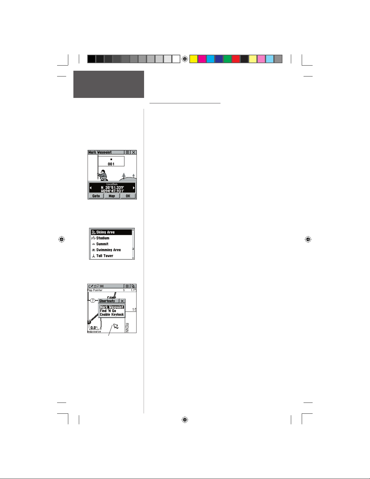
Main Menu Page
Marking
Waypoints
Mark Waypoint Page
Map Symbol List
The Mark (Waypoint) Page
The Mark Waypoint Page allows you to mark and
record your current location as a waypoint and appears
with a graphic name block (man with a fl ag) that displays
the assigned number for that waypoint and a waypoint
symbol.
To mark your current location as a
waypoint:
1. Press IN and hold the CLICK STICK to access the
Shortcut Menu, then highlight ‘Mark Waypoint’
and press IN. You can also access this page by
highlighting the Mark Icon on the Main Menu Page
and then pressing IN on the CLICK STICK. It is
automatically assigned a 3-digit number.
2. To change the name of the waypoint, use the
CLICK STICK to highlight the waypoint name fi eld.
3. To assign an identifying symbol to a waypoint, use
the CLICK STICK to highlight the symbol block just
above the waypoint name.
4. To view the waypoint details, highlight the details
fi eld and press LEFT or RIGHT on the CLICK STICK
to change to the next data fi eld.
5. To save the waypoint, highlight ‘OK’ and press IN
on the CLICK STICK.
6. If you do not want to save it as a new waypoint,
press the PAGE button before pressing any other to
cancel.
To create a waypoint using the map panning
Preliminary
Marking a Waypoint with
the Panning Arrow.
arrow:
1. With the Pan Map feature active, move the panning
arrow (map pointer) to the map item you want and
highlight it.
2. Press IN and release the CLICK STICK to display
the item information page.
3. With the Information Page displayed, highlight the
Options Menu button at the top of the page and
then press the CLICK STICK to open the menu.
4. Highlight the ‘Save As Waypoint’ option and press
the CLICK STICK to save the map item as a
waypoint.
28
190-00284-00_Prelim_FCC.indd 28 9/18/2003, 3:51:07 PM
Page 39
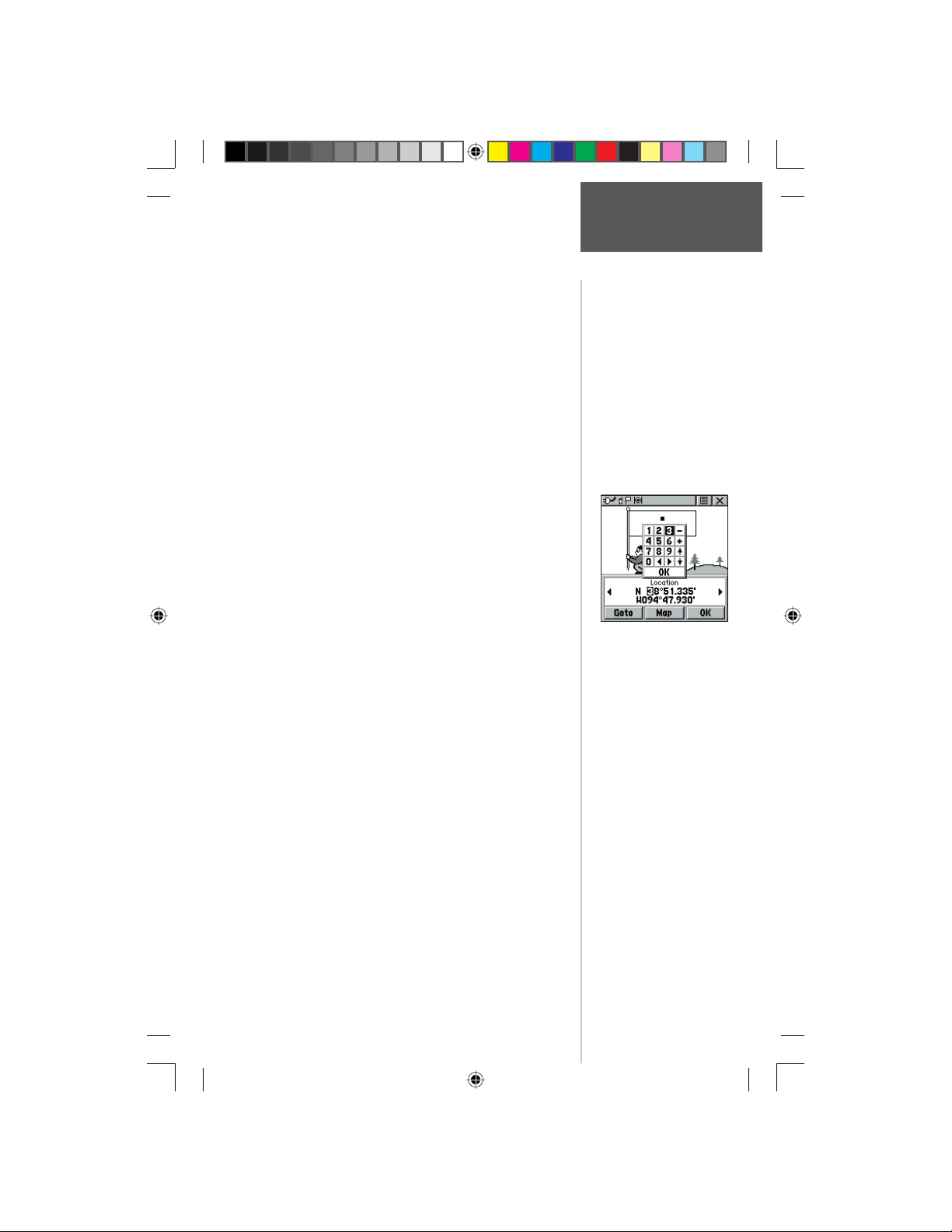
To create a waypoint using the panning
arrow when a map item is not highlighted:
1. With the Pan Map feature active, move the panning
arrow (map pointer) on the map to the location you
want to mark and then, press the CLICK STICK.
2. The Mark Waypoint Page displays, automatically
assigning a number to the waypoint.
Be certain to press and release the CLICK STICK
for this operation. Pressing IN and holding the
CLICK STICK displayed the Shortcut Menu.
To create a waypoint by manually entering
its coordinates (lat/lon):
1. Press IN and hold the CLICK STICK to access the
Shortcut Menu, then highlight ‘Mark Waypoint’ and
press IN or use the Find ‘N Go to view a previous
waypoint.
2. Highlight the details fi eld and press LEFT or RIGHT
on the CLICK STICK to change to the Location fi eld.
Press IN and enter the new coordinates using the
numerical keyboard. Highlight and press ‘OK’ when
fi nished.
3. You may also change the waypoint name and/or
symbol or add notes.
To move a waypoint by dragging it:
1. Use the Find ‘N Go Menu to display the Waypoint
Page for the waypoint you want to move.
2. Highlight and press the ‘Map’ on-screen button to
display the map for the waypoint.
3. With the waypoint highlighted by the panning
4. Use the panning arrow to drag the waypoint
5. Press the PAGE button before pressing the
Preliminary
arrow, press IN and release the CLICK STICK. The
word “Move” displays beneath the panning arrow.
to the new location and then press IN on the
CLICK STICK to place it.
CLICK STICK to cancel moving of the waypoint and
return to the Main Pages.
Main Menu Page
Waypoints
Creating a
Waypoint by entering
coordinates.
190-00284-00_Prelim_FCC.indd 29 9/18/2003, 3:51:08 PM
29
Page 40
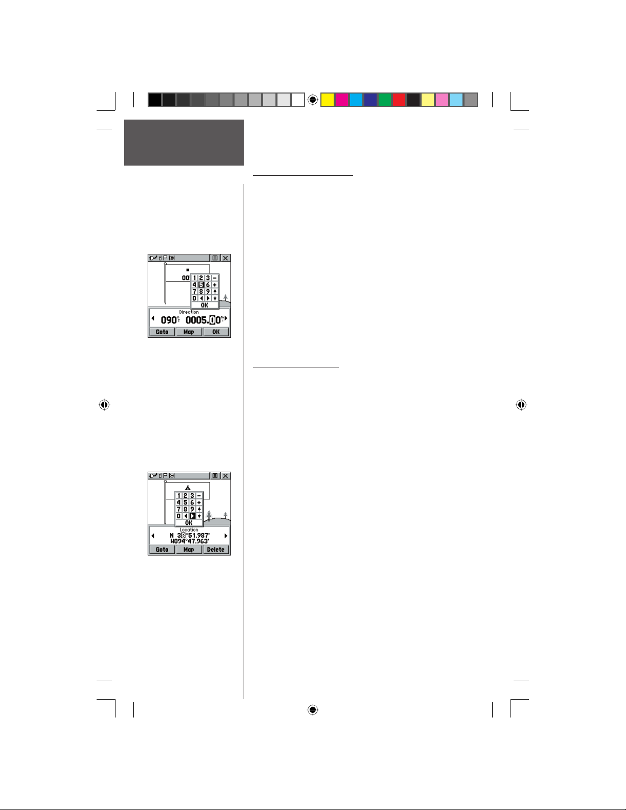
Main Menu Page
Waypoints
Enter Distance and
Bearing to project.
Preliminary
Using the keyboard to edit.
Projecting a Waypoint
Projecting a waypoint from any map item (another
waypoint, etc.) allows you to establish a new waypoint on a
bearing and distance projected from that map item.
To project a waypoint:
1. Select a map item from the Find ‘N Go Menu.
2. Highlight the Option Menu on-screen button at
the top of the Information Page and press the
CLICK STICK IN to display the options. Highlight
‘Project Waypoint’ and press IN.
3. Highlight either the bearing or distance fi eld, then
press the CLICK STICK IN to display the numerical
keyboard. Move from numeral to numeral pressing the
CLICK STICK to enter numbers, then highlight ‘OK’
and press IN to fi nish.
Editing a Waypoint
A waypoint or contact can be edited to change the map
symbol, name, coordinates, elevation or add notes. It can
also be deleted.
To edit a waypoint:
1. Use the Find ‘N Go Menu to display the waypoint/
contact or highlight it on the Map Page and press IN.
2. To view the details, highlight the details fi eld and
press LEFT or RIGHT on the CLICK STICK to change to
the next data fi eld. To make changes to the waypoint
map symbol, name, location coordinates, elevation
fi elds and notes, highlight the desired fi eld and press
the CLICK STICK IN to display the keyboard. (For
Notes, highlight ‘Edit’ and press IN to start entering
data, up to 30 characters.) Highlight the desired
characters on the keyboard to enter new data and
then select ‘OK’ and press IN to close the keyboard.
3. Highlight the ‘OK’ button the press the CLICK STICK
to save the changes.
To delete a waypoint or contact:
1. Use the Find ‘N Go feature to display the point.
2. From the Highlight the ‘Delete’ button and then press
the CLICK STICK. Confi rm the deletion.
30
190-00284-00_Prelim_FCC.indd 30 9/18/2003, 3:51:09 PM
Page 41
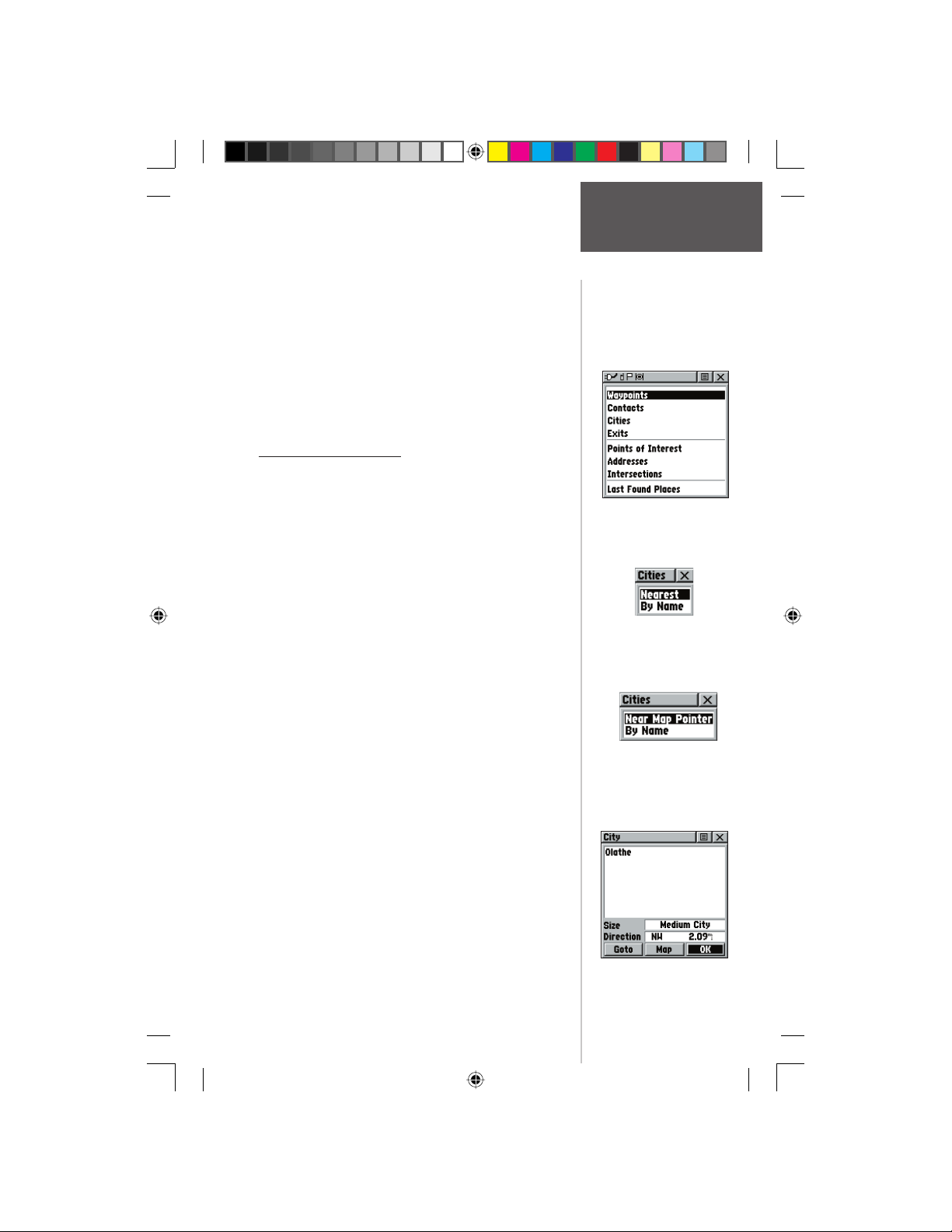
To save Map or Find ‘N Go Menu items as
waypoints:
1. Access the Information Page for the desired item
(highlighted from the map or selected from the Find
‘N Go Menu).
2. Open the Options Menu at the top of the page,
select ‘Save As Waypoint’ and press IN on the
CLICK STICK to save the item to the Waypoints List.
3. Highlight the ‘Save As Waypoint’ option and press
Straight Down on the CLICK STICK.
The Find ‘N Go Menu
The Find ‘N Go Menu allows you to fi nd stored
locations (waypoints) and map items (cities, exits, etc.).
They can be found by name or by those nearest to your
current location (Position Icon). If you are using certain
MapSource data, the list of fi nd locations is expanded to
include categories for Points of Interest, Street Addresses
and Intersections. If an option is grayed out (disabled),
you will need to load map detail using MapSource to use
that option.
To access the Find ‘N Go Menu:
1. Hold IN on the CLICK STICK button to access the
Shortcut Menu. Highlight ‘Find ‘N Go’ press IN.
or
2. From the Main Menu, highlight ‘Find ‘N Go and
press IN on the CLICK STICK.
For some categories, there are two methods of listing. The “By Name” list contains every item in the map
database for the selected category, while the “Nearest” list
Preliminary
contains only those items that are near to your Current
Location or the Map Pointer. Categories listed by either
method displays a choose prompt.
Main Menu Page
Find ‘N Go
Find ‘N Go Menu
Find Page using your
current location as a point
of reference
‘Near Map Pointer’ or ‘By
Name’ Prompt displays
when using Map Pointer
These pages are structured with a set of sub-menus and
location information pages that guide you through the
process of fi nding locations. Use them to construct a
Route, establish a direct line of travel (Goto), or when
gathering information.
Item Information Page
190-00284-00_Prelim_FCC.indd 31 9/18/2003, 3:51:10 PM
31
Page 42
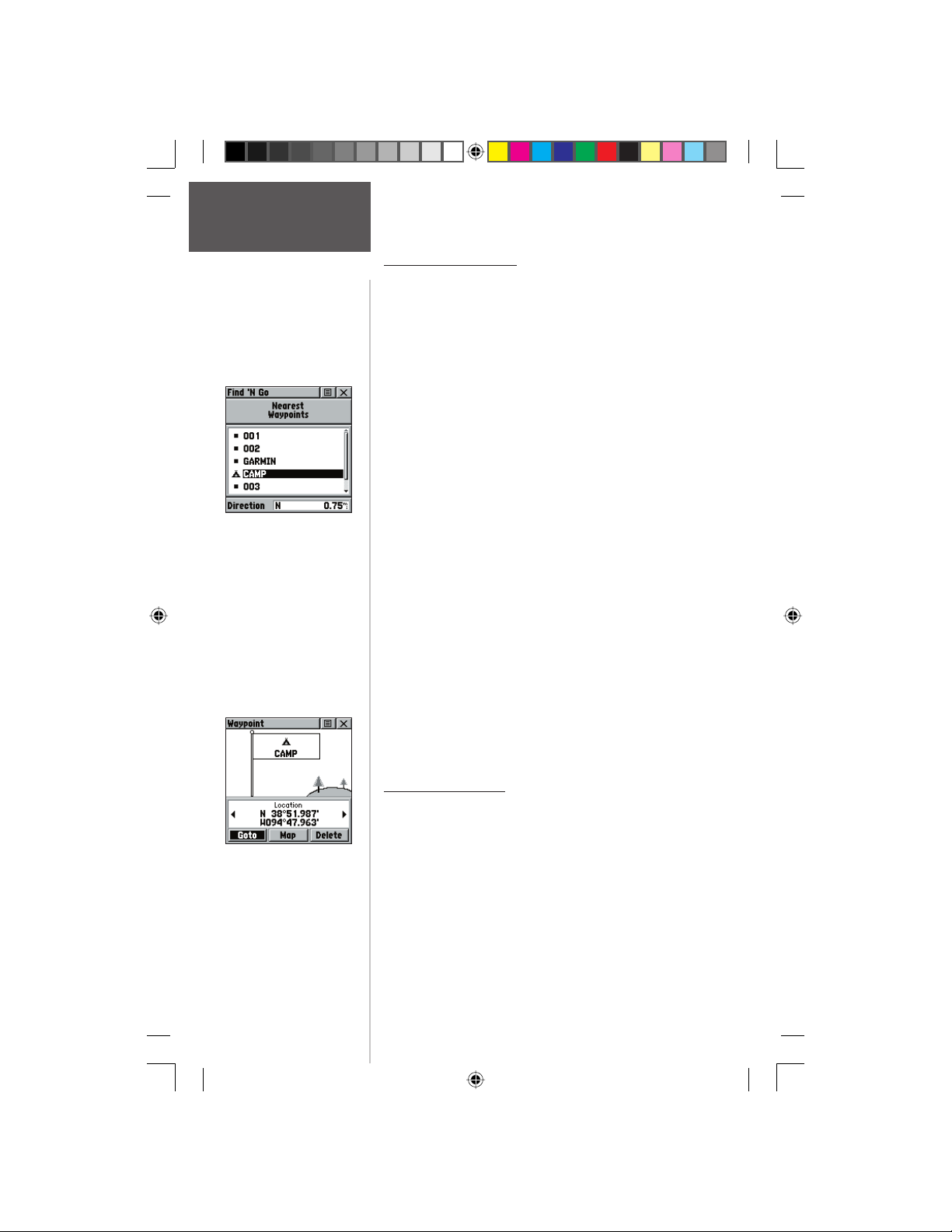
Main Menu Page
Finding Items
Waypoint Find List
Finding a Waypoint
Waypoints that you have created and stored in the Rino
can be found by selecting the “Waypoint’ option from the
Find ‘N Go Menu. You can fi nd a waypoint from the list of
waypoints using the ‘By Name’ or ‘Nearest’ options as explained on the previous page. When selected from the list,
the waypoint displays on the Waypoint Information Page.
The Waypoint Information Page displays the waypoint
name or number, a map symbol, the location in lat/lon,
elevation, distance, bearing, and three on-screen buttons for
‘Goto’, ‘Map’, and ‘OK’ functions.
To fi nd a waypoint:
1. Use the CLICK STICK to select the Waypoint option
from the Find List and then press it IN to display a
prompt to select ‘By Name’ or ‘Nearest’. Select, then
press the CLICK STICK IN to display the Waypoints
List.
2. Use the CLICK STICK to select the desired waypoint
from the list and then press it IN to display the
Information Page for that waypoint.
3. With the Information Page displayed, you can select
‘Goto’ to create a direct line of travel to the
waypoint. Select ‘Map’ to view the waypoint location
on the map or select ‘OK’ to close the page.
4. Use the Options Menu to send the location, add it to
an existing route, project a new waypoint from this
location, view sun and moon, and best fi shing and
hunting time information for this waypoint.
Preliminary
Finding a Contact
Contacts that you have received in the Rino can be
found by selecting the ‘Contacts’ option.
1. Highlight ‘Contacts’ and press the CLICK STICK IN.
Waypoint Information
Page
2. From the Contacts List, select the desired contact and
press the CLICK STICK IN.
3. If the contact did not have a GPS location on the last
transmission, a ? mark will appear below the fl ag. To
view the contact details, highlight the details fi eld and
press LEFT or RIGHT on the CLICK STICK to change to
the next data fi eld.
32
190-00284-00_Prelim_FCC.indd 32 9/18/2003, 3:51:10 PM
Page 43
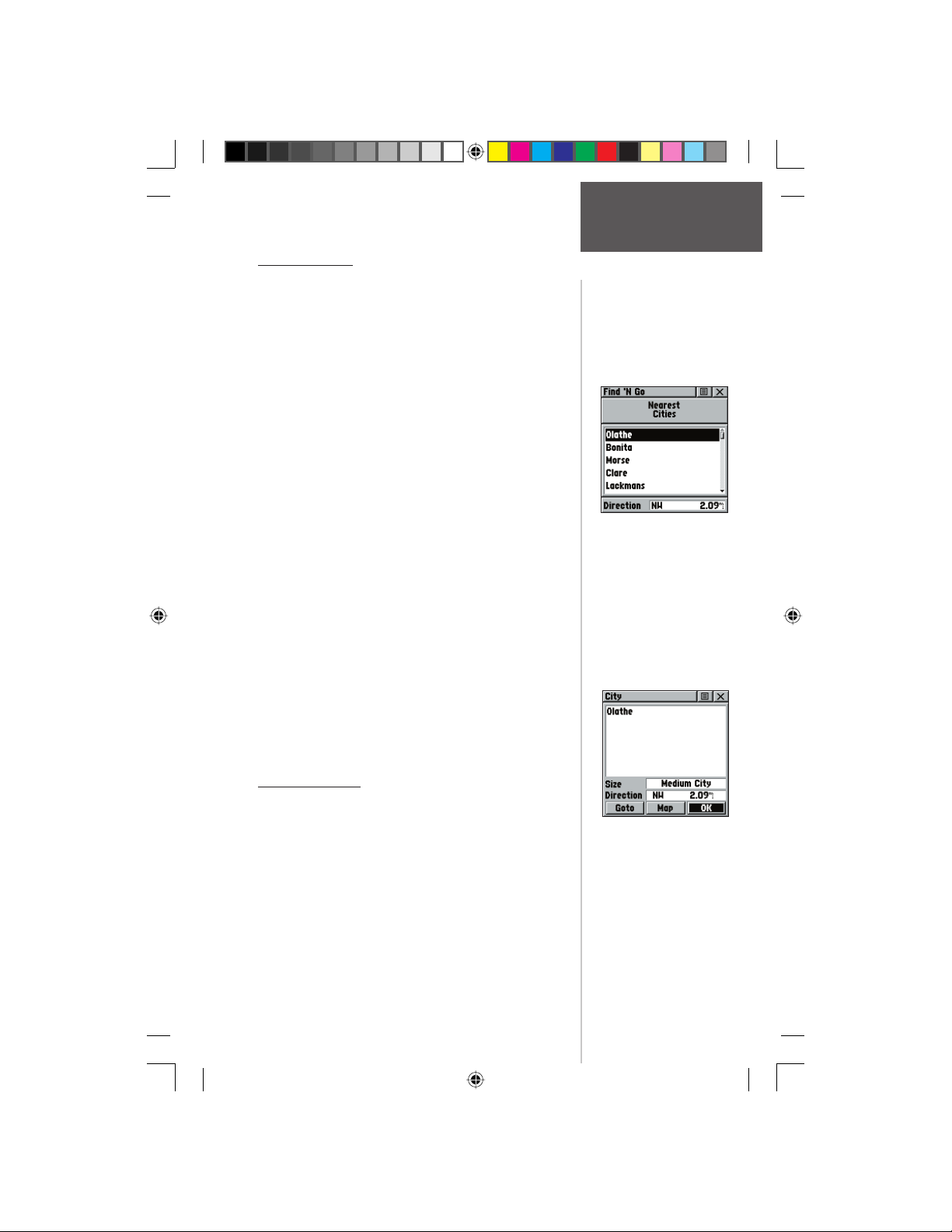
Main Menu Page
Finding a City
Cities can be found by selecting the ‘Cities’ option
of the Find ‘N Go Menu, selecting the city from the list
of ‘Nearest’ or ‘By Name’, and then displaying the City
Information Page.
The City Information Page for the selected city displays the city name, the size by population, and distance
from your location. You can view it on the map or create
a Goto direct route to the city from your current location,
or from a location defi ned by the Panning Arrow (Map
Pointer). You can also save it as a waypoint, or add it to
an existing route.
To fi nd a city:
1. Use the CLICK STICK to select the ‘Cities’ option,
then press it IN to display the fi nd ‘By Name’ or fi nd
by ‘Nearest’ prompt. Selecting ‘By Name’ displays
the keyboard as an alternative scrolling through the
list of nearest cities.
2. If using fi nd ‘By Name’, begin spelling the name
of the city by using the keyboard. When you have
entered enough characters to defi ne the name, a
match list displays. If you are using fi nd ‘By Nearest’
scroll through the list to fi nd the city you want. Use
the CLICK STICK to select the desired city from the
list and then press it IN to display the Information
Page for that city.
3. With the Information Page displayed, you can select
‘Goto’, ‘Map’, or ‘OK’ options.
Find List for Nearest Cities
Finding Items
Finding an Exit
Preliminary
You can use the Find Exit option to locate a nearby
exit on an interstate highway. Exits are listed only by
‘Nearest’. Exit information pages provide a variety of
information about services near each exit, including rest
City Information
Page
stops, lodging, restaurants, service stations, etc. Some
services (i.e. service stations) on this page can be selected
and a separate information page displays with specifi c
information concerning what types of fuel, mechanical
and food services are available.
190-00284-00_Prelim_FCC.indd 33 9/18/2003, 3:51:11 PM
33
Page 44
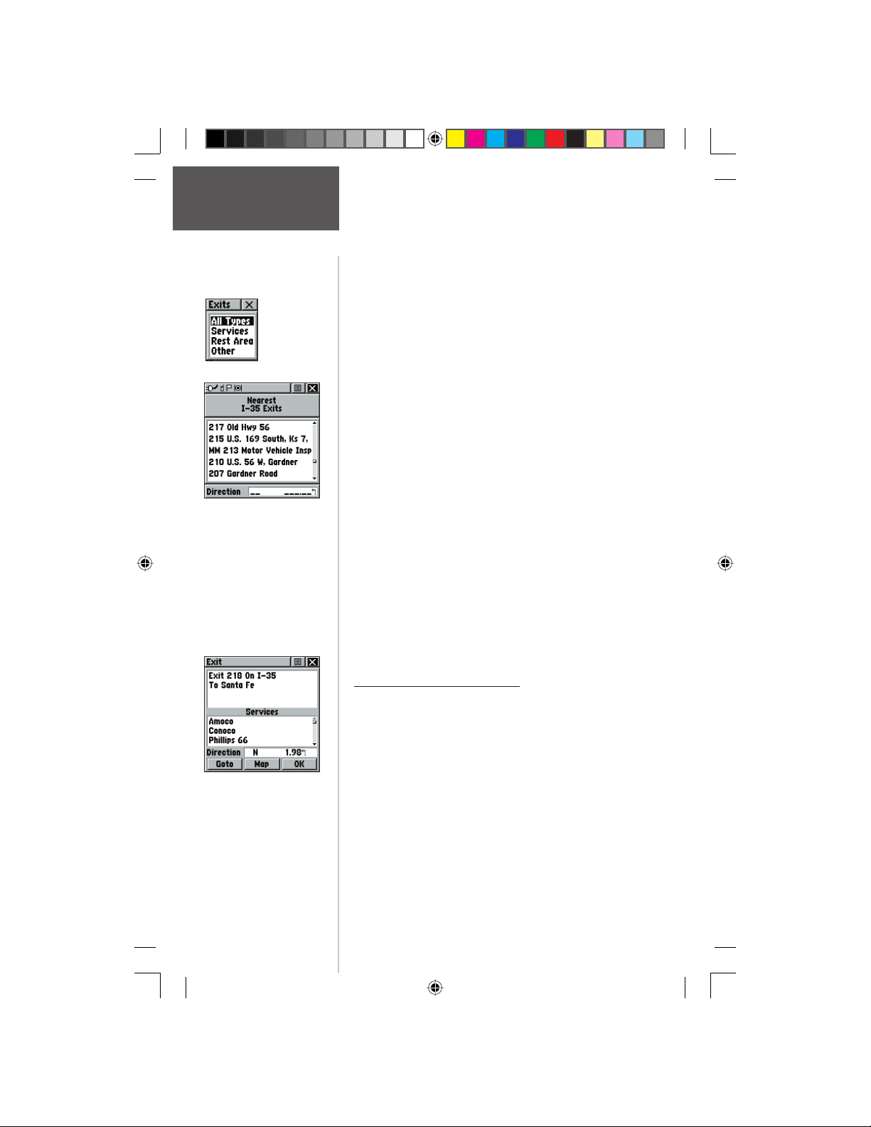
Main Menu Page
Finding Items
List of Exit
Types
Exits List
To fi nd an exit:
1. Use the CLICK STICK to highlight ‘Exits’ and then
press it IN to display the Exit List.
2. Highlight and select an exit type by pressing IN on the
CLICK STICK.
3. A list of exits nearest to you displays. The title box
indicates the interstate highway which is served by
the exits. Two fi elds at the bottom of the page indicate
distance and bearing to the exit.
4. Scroll through the list to highlight the desired exit.
5. Press IN on the CLICK STICK to display the
Information Page for that exit. This page contains the
exit description with a list of available services near
that exit along with the distance and bearing fi elds.
6. Use the CLICK STICK to move to the list of services
and highlight a selection from the list.
7. Press IN on the CLICK STICK to display the
Information Page for the selected service.
The Exit Services Information Page displays the name
of the service, its direction from the exit, and a list of
the services available, each marked by a check.
At the bottom of these Information Pages are on-
screen buttons for ‘Goto’, ‘Map’, and ‘OK’.
8. Use the Options Menu at the top of the page to save
the exit as a waypoint, send the location, project a
waypoint, or add to an existing route.
Finding a Point of Interest
You can use the Find Point of Interest option to locate
Preliminary
a nearby restaurant, lodging, landmark, public building,
park, etc. However, you must have transferred a MapSource
MetroGuide map to the unit map database. Otherwise, this
option, plus Address and Intersection options, are grayed
Exit Information Page
out and are not functional.
Here is a list of Point of Interest categories:
Food & Drink Services
Lodging Transportation
Attractions Emergency & Govt.
Entertainment Manmade Places
Shopping
34
190-00284-00_Prelim_FCC.indd 34 9/18/2003, 3:51:12 PM
Page 45
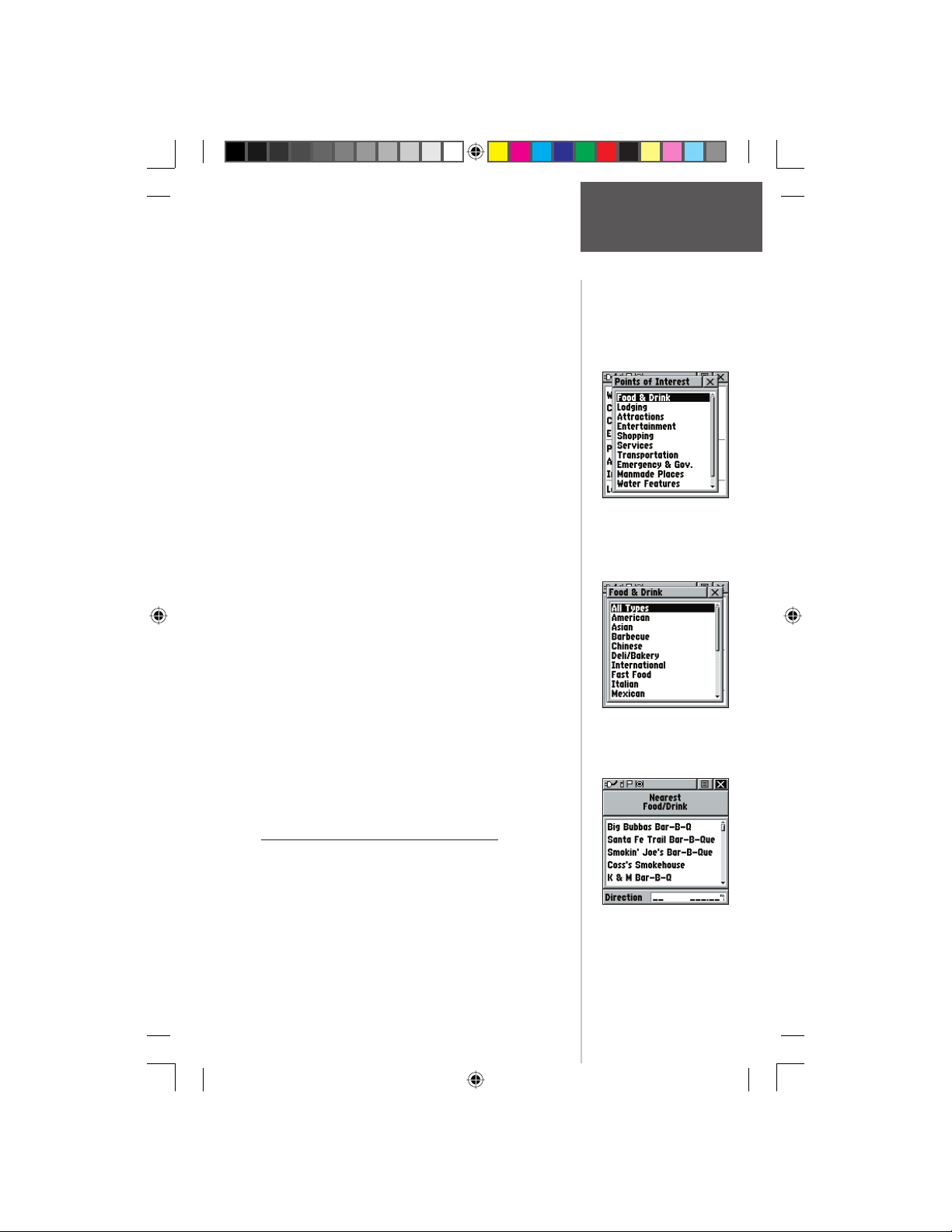
Main Menu Page
In many instances, these categories are subdivided
into types, such as in the instance of Food & Drink.
When you select Food and Drink from the list of categories, you are then presented with a list of types which
includes ‘All Types’ and cuisine options such as American,
Asian, Barbecue, Chinese and many more.
Once you have selected an item, you can display the
Information Page for that item. You can then use the onscreen buttons to ‘Goto’ or view the location on the ‘Map’;
or use the Options Menu for more choices.
To fi nd a point of interest:
1. Use the CLICK STICK to highlight ‘Points of
Interest’ and then press it IN to display the Points of
Interest Categories List.
2. Use the CLICK STICK to select the desired category
and then press it IN to display the Types List.
3. Use the CLICK STICK to select the desired type and
then press it IN to display the list for that type.
4. Use the Options Menu at the top of page to select
from either ‘By Name’ or ‘Nearest’ options. Selecting
‘By Name’ displays a keyboard allowing you to
enter the characters of the name you want. A list
of matches displays when enough characters are
entered.
5. Use the CLICK STICK to highlight your selection
from the list and then press it IN to display the
Information Page for that item.
6. Use the on-screen buttons to ‘Goto’ or view on the
‘Map’, or use the page Options Menu.
Preliminary
Food & Drink Categories
Finding Items
Points of Interest List
Finding an Address or Intersection
You can enter a street number, choose a street name
from a list and fi nd an address within the area of map
data coverage or enter two street names and locate the
intersection. To use these options, however, you must be
using a MapSource MetroGuide which provides this type
Nearest Barbecue List
of map data.
190-00284-00_Prelim_FCC.indd 35 9/18/2003, 3:51:13 PM
35
Page 46
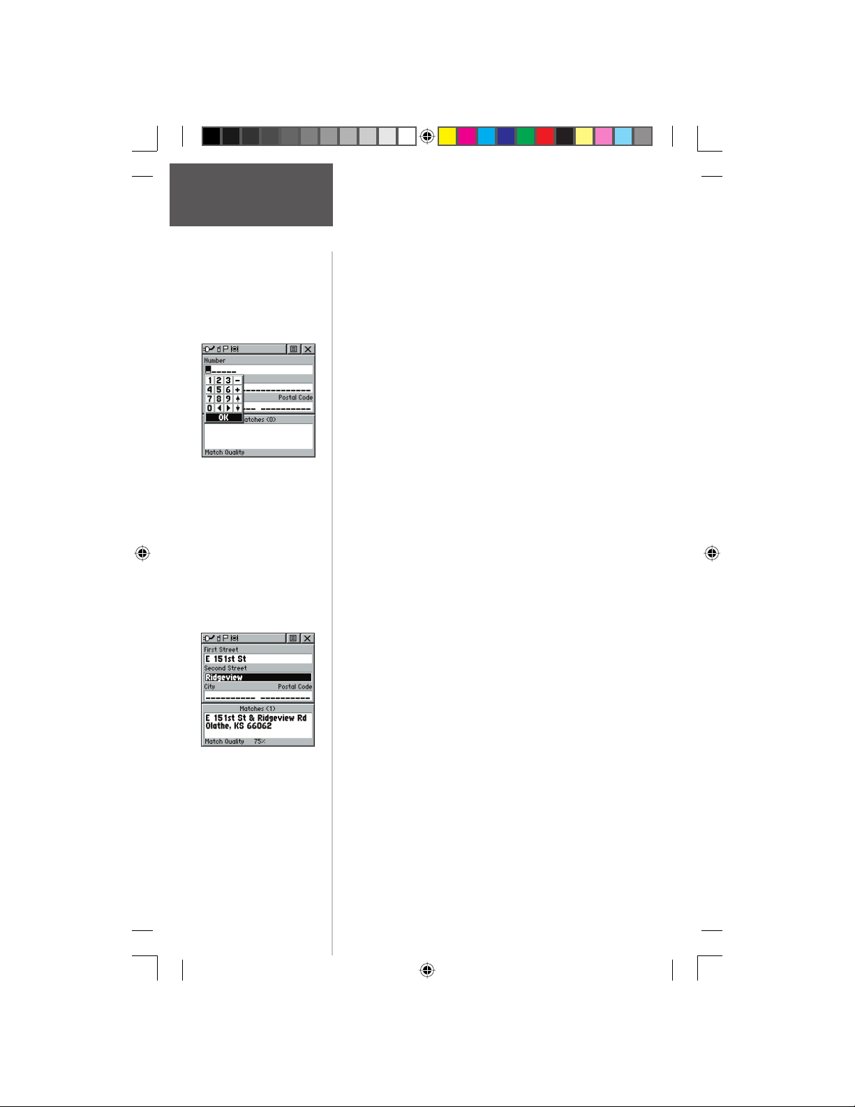
Main Menu Page
Finding Items
Entering an Address
Preliminary
Find Intersection Page
To locate an address:
1. Use the CLICK STICK to highlight ‘Address’ and
press it IN to display the ‘Find Address’ page.
2. Highlight the’ Number’ fi eld and use the keyboard
for entering numbers.
3. Move to the ‘Street’ fi eld using the CLICK STICK.
4. Press IN on the CLICK STICK to display the ‘Select
Street Name’ list. Find the street by using the
keyboard to enter characters until a list appears.
5. With the desired street highlighted, press IN on
the CLICK STICK to place the street name on the
Find Address page. Repeat this process for city and
postal codes, if desired. A window at the bottom of
the page displays a list of matches and the quality
of each match. You may also use the Options Menu
to ‘Clear City’, ‘Clear Postal Code’ or ‘Clear All’.
6. Use the on-screen buttons at the bottom of the
page to ‘Goto’, view the item on the ‘Map’, ’OK’ to
close, or use the Options Menu for other choices.
To locate an intersection:
1. Display the Find ‘N Go Menu and use the
CLICK STICK to highlight the ‘Intersection’
category and press it IN to display the ‘Find
Intersection’ page.
2. Highlight the fi rst ’Street’ fi eld and then press IN on
the CLICK STICK to display the ‘Street‘ list.
3. Enter the name of the street in the name fi eld at
the top of the list using the keyboard data entry
method. Once you have spelled enough of the street
name, you a match displays, often with several
streets on the list. Press IN on the CLICK STICK to
move the highlight to the street list and then scroll
up or down until you fi nd the street name you want.
Press it IN to place the name in the fi eld.
4. Highlight the best match and then press IN on the
CLICK STICK to display the Information Page for
the intersection. Use the on-screen buttons at the
bottom of the page to ‘Goto’, view the item on the
‘Map’, ‘OK’ to close, or use the Options Menu for
other choices.
36
190-00284-00_Prelim_FCC.indd 36 9/18/2003, 3:51:14 PM
Page 47
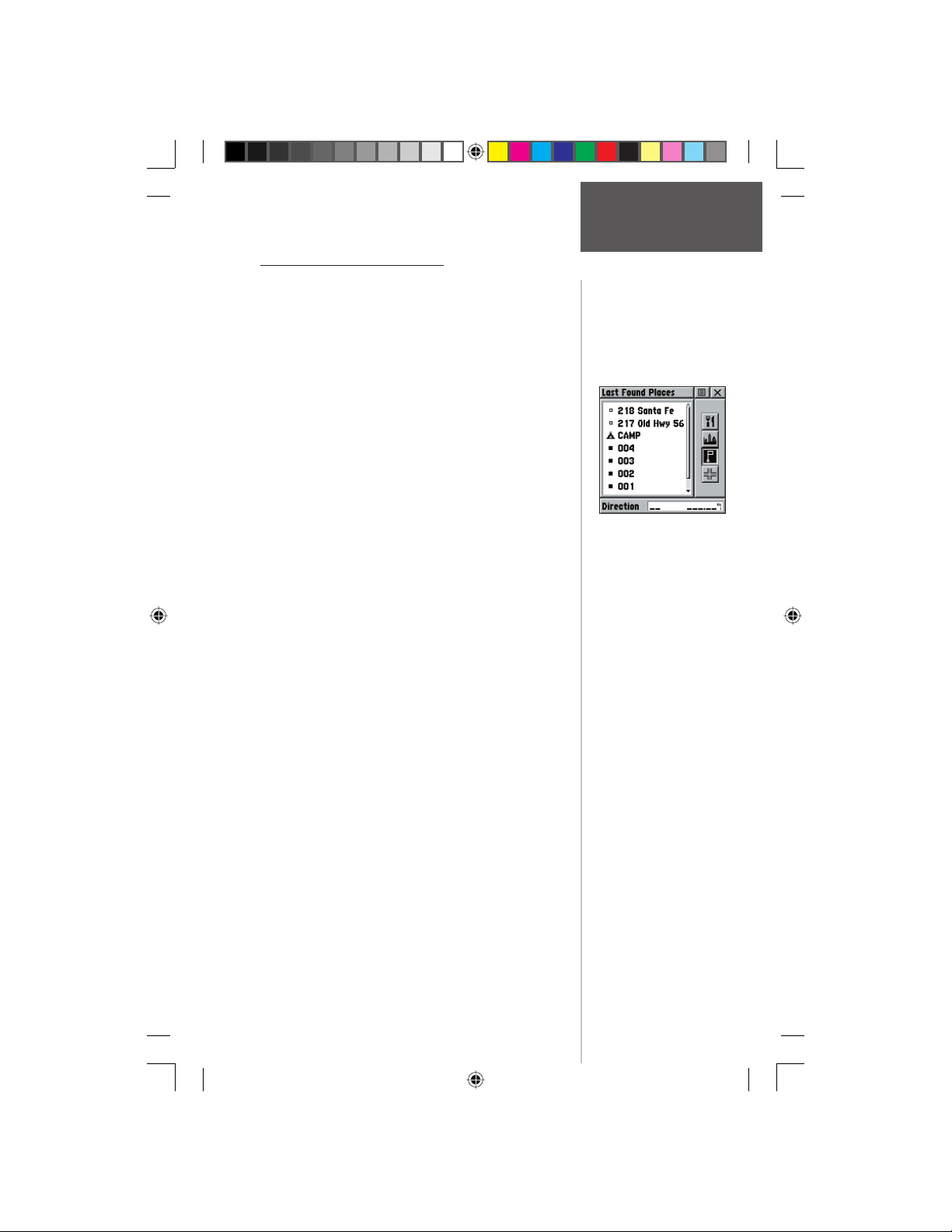
Finding a Last Found Place
You can use the Recently Found Places option to
locate Points of Interest, Cities, Waypoints or Contacts
and Intersections and other locations you have recently
retrieved. The process for fi nding recent points from the
Find ‘N Go list is the same as fi nding a regular waypoint.
To fi nd a ‘Last Found Place’:
1. Use the CLICK STICK to select the ‘Last Found
Places’ option from the Find ‘N Go List and then
press it IN.
2. Press UP or DOWN on the CLICK STICK to
highlight the desired sub-page button, which will
display the options list for that sub-page (Points of
Interest, Cities, Waypoints/Contacts or Intersections)
to the left.
3. Press LEFT (Pressing RIGHT will return you to the
sub-page buttons), then UP or DOWN on the
CLICK STICK to highlight an item on the list
and press IN on the CLICK STICK to display the
Information Page for that item.
4. With the Information Page displayed, you can select
‘Goto’ to create a direct line of travel to the item.
Select ‘Map’ to view the waypoint location or select
‘OK’. For Waypoints and Contacts, you may also
choose to ‘Delete’ to permanently remove that item.
5. Use the page Options Menu to send the location of
that point, project a new waypoint from its location,
set a proximity circle, add the item to an existing
route, or view sun/moon or hunt/fi sh position data
for this time and date.
Preliminary
Main Menu Page
Finding Items
Last Found Places Page
190-00284-00_Prelim_FCC.indd 37 9/18/2003, 3:51:14 PM
37
Page 48
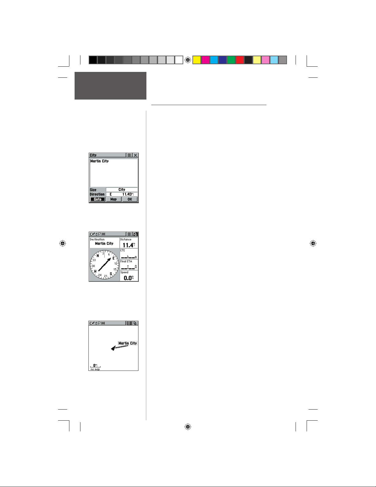
Main Menu Page
Using a Goto
Information Page
Navigation Page
Preliminary
Using a Goto to Navigate to a Destination
The Goto function allows you to create a direct route
to a destination, (waypoint, city, or point of interest).
Once you have accessed the Information Page for an item,
use the Goto button at the bottom of the page to initiate
travel to a map item using the Map and Navigation Pages
for guidance.
To activate a Goto:
1. Use the Find ‘N Go Menu to access the Information
Page for any desired destination and use the
CLICK STICK to highlight the Goto button.
2. Press IN on the CLICK STICK to start navigation.
3. Observe the Navigation Page, it displays the name
of your destination, the distance from your current
location, and a Bearing Pointer indicating the
direction you should travel. The time required to
reach your destination displays when you begin to
travel and establish a predicted rate of movement.
The Data Fields to the right of the page display
information relative to your travel as appropriate for
the type of data selected to appear in those fi elds.
4. Use the PAGE button or Main Page Menu to access
the Map Page and observe your movements and
a dark line indicating the direct path from your
current location to your destination.
5. Use the Bearing Pointer on the Navigation Page to
maintain travel in the right direction and observe
distance and time information to monitor your
progress.
6. When you are close to your destination, an “Arriving
at Destination” message appears. If you move past
the destination the Bearing Pointer reverses and the
distance display increases.
To stop navigating:
1. Highlight the on-screen Options Menu button at the
top of the Navigation or Map Page and press IN on
the CLICK STICK.
2. Select ‘Stop Navigation’, then press IN on the
A Map Page Goto
CLICK STICK.
38
190-00284-00_Prelim_FCC.indd 38 9/18/2003, 3:51:15 PM
Page 49
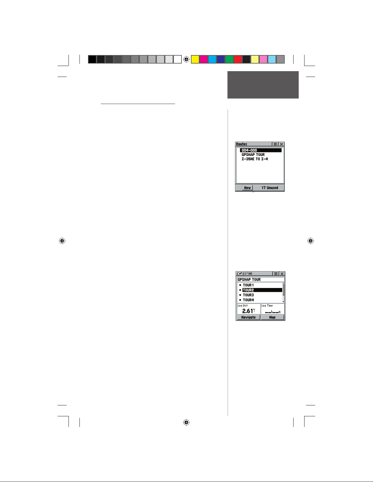
Creating and Using a Route
Route navigation allows you to create a sequence
of intermediate waypoints which lead you to your fi nal
destination. The Rino stores 20 routes, each with up to 50
waypoints. A route can be created and modifi ed from the
Route Page, and waypoints can be added to a route from
the Find ‘N Go Menu. More complex routes can be created using a PC and MapSource mapping programs and
then transferred to the unit memory.
To create a route:
1. Access the ‘Routes’ page from the Main Menu. The
page has a ‘New’ button, a list of routes, and the
number of unused routes.
2. Use the CLICK STICK to highlight the ‘New’ button
and press it IN to display the route Setup Page.
3. With an empty row (dashed) in the route list
highlighted, press IN on the CLICK STICK to
display the Find ‘N Go Menu.
4. Use the Find ‘N Go Menu to select a route waypoint
from one of the Find ‘N Go Menu categories and
display the Information Page for the selected
waypoint, city, exit, point of interest, etc. Highlight
the on-screen ‘Use’ button and press IN on the
CLICK STICK to place it on the Routes List.
5. To add more waypoints to the route, repeat the
process in Steps 3 and 4. The route is named for the
fi rst and last waypoints on the route.
You can add waypoints to the end of an existing route
at any time by using the Find ‘N Go Menu.
Preliminary
To add a Find ‘N Go Menu item to a route:
1. Select an item from the Find ‘N Go Menu and
display its Information Page. If a Contacts is used
in a route, the route will change as the Contact’s
position is updated, or it may be saved as a
Waypoint to serve as a stationary point.
2. Display the page Options Menu and select the ‘Add
To Route’ option to display the Routes List.
3. Highlight and select the route desired and then
press IN on the CLICK STICK. A “Waypoint Added
Successfully” message displays.
Main Menu Page
Routes
The Routes Page with a list
of Routes and the number
of Unused Routes.
A Route with list
of waypoints.
39
190-00284-00_Prelim_FCC.indd 39 9/18/2003, 3:51:16 PM
Page 50
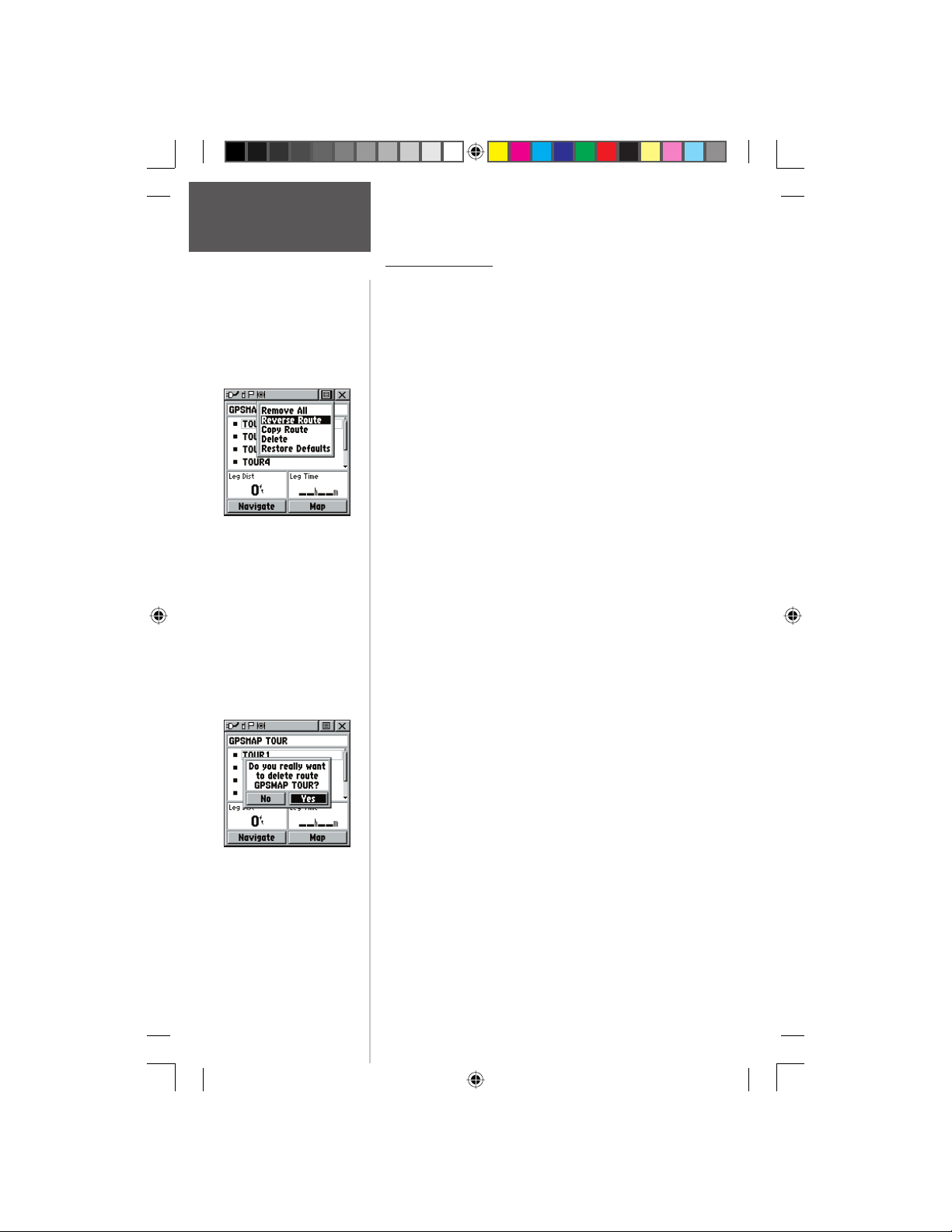
Main Menu Page
Editing a Route
Routes
A Route Options Menu
To remove all waypoints:
1. Select the on-screen page options button from
the Route Page and press the CLICK STICK IN to
access the Options Menu.
2. Highlight the ‘Remove All’ option and then press IN
on the CLICK STICK to remove all waypoints from
the list. When you see the prompt “Do you really
want to remove all waypoints from the route?”,
select “Yes”.
To reverse the route:
1. Select the on-screen page options button from
the Route Page and press the CLICK STICK IN to
access the Options Menu.
2. Highlight the ‘Reverse Route’ option and then press
IN on the CLICK STICK to reverse the order of
waypoints in the list. To change the route back to
the original order, repeat this process.
To copy the route:
1. Select the on-screen page options button from
the Route Page and press the CLICK STICK IN to
access the Options Menu.
2. Highlight the ‘Copy Route’ option and then press
IN on the CLICK STICK to copy. The copied route
displays on the Routes Page and is named the same
but followed by a numeral 1. You may then rename
and/or modify the copied route.
To delete the route:
Preliminary
Delete Route Prompt
1. Select the on-screen page options button from
the Route Page and press the CLICK STICK IN to
access the Options Menu.
2. Select ’Delete’ and then press IN on the
CLICK STICK. When you see the prompt “Do you
really want to delete route?”, select “Yes”.
To restore default settings for the route:
1. Select the on-screen page options button from
the Route Page and press the CLICK STICK IN to
access the Options Menu.
2. Select ’Restore Defaults’ and then press IN on the
40
190-00284-00_Prelim_FCC.indd 40 9/18/2003, 3:51:17 PM
CLICK STICK to restore factory settings.
Page 51
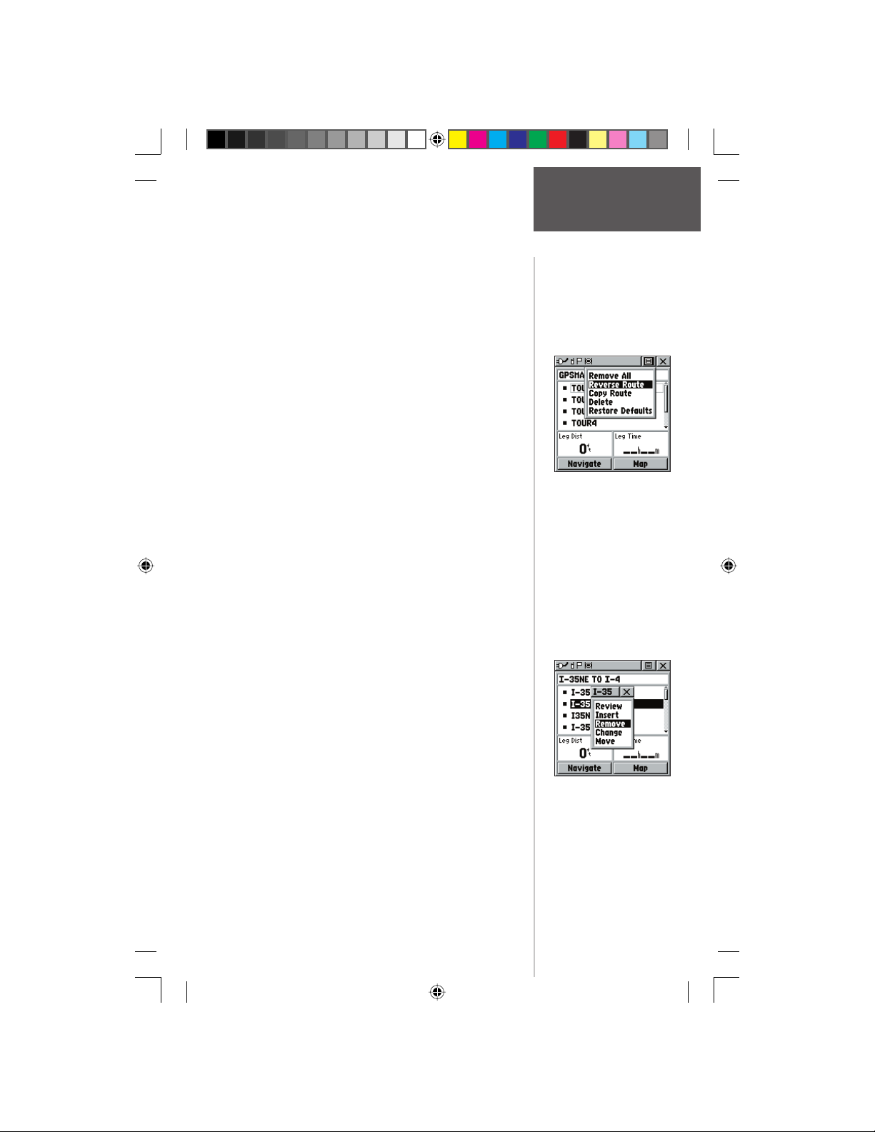
To review a route point:
1. Select the point from the Route Points List and press
the CLICK STICK IN to access the Options Menu
for the waypoint.
2. Highlight ‘Review’ and then press IN on the
CLICK STICK to display the Information Page.
3. Highlight the on-screen ‘OK’ button and then press
IN on the CLICK STICK to return to the Route List.
To insert a new point on the route list:
1. Select the row where you want the new point
inserted before. Press the CLICK STICK IN to
access the Options Menu.
2. Highlight ‘Insert’ and press IN on the CLICK STICK
to display the Find ‘N Go Menu and select a new
waypoint, city, exit, point of interest, etc.
3. With the new point highlighted, press IN on the
CLICK STICK to display the Information Page for
the new point and then select the on-screen ‘OK’
button to add it the route.
To remove a point from the route list:
1. Select the point that you want to remove from
the Route Waypoints List and press IN on the
CLICK STICK to display the Options Menu.
2. Highlight ‘Remove’ and press IN on the
CLICK STICK to remove the waypoint from the list.
Main Menu Page
Routes
Route Waypoint
Options Menu
To change a route point:
1. Select the waypoint that you want to change from
the Route Waypoints List and press IN on the
CLICK STICK to display the Options Menu.
Preliminary
2. Highlight ‘Change’ and press IN on the
CLICK STICK to display the Find ‘N Go Menu or
create a new waypoint and add it to the points list.
3. Select a new waypoint, access its Information Page
and press the on-screen ‘Use’ button to replace the
old route waypoint.
190-00284-00_Prelim_FCC.indd 41 9/18/2003, 3:51:17 PM
Removing a Route Point
41
Page 52
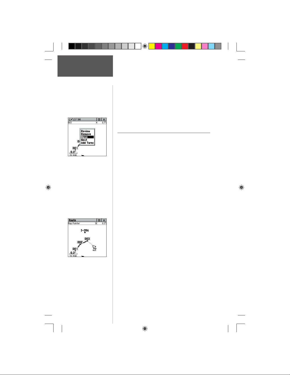
Main Menu Page
Routes
Moving a Route Waypoint
by clicking and dragging.
Preliminary
To move a route point:
1. Select the point from the Route Points List and
press the CLICK STICK IN to access the Options
Menu for the waypoint.
2. Highlight the ‘Move’ option and press IN on the
CLICK STICK to select the waypoint.
3. Use the CLICK STICK to move the point up or
down in the list. Press IN on the CLICK STICK to
leave the waypoint in the new list order.
Adding or Editing from the Route Map Page
You can use the panning arrow with the Route Map
Page displayed to add or edit route waypoints.
To add a point at either end of a route:
1. Select the Route from the Routes List and press the
CLICK STICK IN to display the Route Page.
2. Highlight the on-screen ‘Map’ button at the bottom
of the page and press IN on the CLICK STICK to
display the Route Map Page.
3. Use the CLICK STICK to move the panning arrow
to either end of the displayed route until the end
point is highlighted. Then press it IN to display the
map Options Menu and select ‘Add Turns’. This
option appears only when highlighting the end
point of a route.
4. Move the panning arrow to a map item or location
where you would like to extend the route and press
IN on the CLICK STICK to display the Information
Page for the new point. Press the on-screen ‘Use’
button to return to the map page and then press it
again to place the new waypoint.
To add a route point within a route:
1. Follow steps 1 and 2 in the previous instruction.
Adding a Route Waypoint
to an end point on the
Route Map Page
2. Use the CLICK STICK to move the panning arrow
to a route line. When the arrow touches the line, the
line becomes thin. Press IN on the CLICK STICK to
display the word ‘ADD’ next to the line.
42
190-00284-00_Prelim_FCC.indd 42 9/18/2003, 3:51:18 PM
Page 53
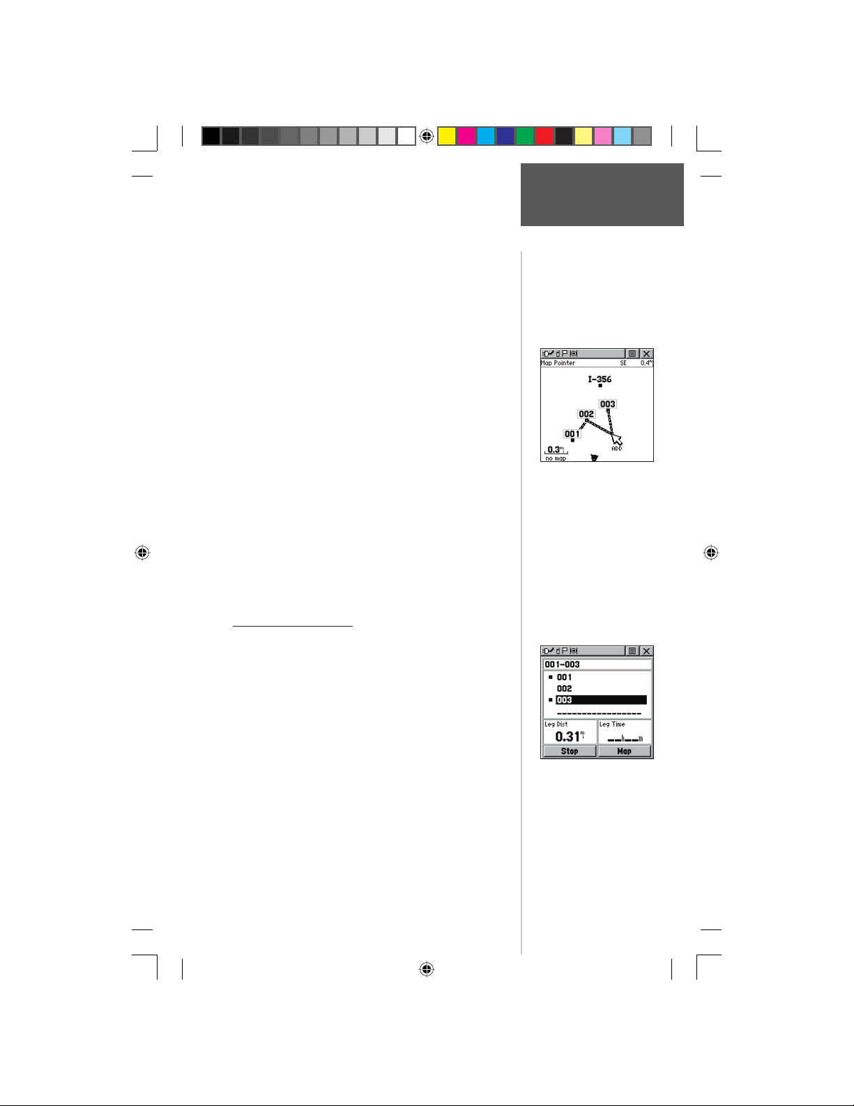
3. Drag the line to a map item or other location where
you want to establish a new waypoint and then
press IN on the CLICK STICK to place the new
waypoint. A waypoint information page displays.
Press the on-screen ‘OK’ button to save the new
waypoint, then press it again after returning to the
Route Map.
To review or remove a route point:
1. Select the Route from the Routes List and press the
CLICK STICK IN to display the Route Page.
2. Use the CLICK STICK to highlight the desired route
and press IN to display the Route Page for that route.
3. Use the CLICK STICK to move the map panning
arrow to the point you want to review and press
IN to pop-up the Options Menu. Select ‘Review’ or
‘Remove’ and press IN again to either display the
Information Page or remove it from the route.
To view the next point in the route:
1. Follow Steps 1 and 2 above.
2. Place the map panning arrow on the point you are
currently viewing and press IN to display the Options
Menu. Select ‘Next’ and press IN again to view the
next waypoint.
Main Menu Page
Routes
Adding a new waypoint
within a Route
Navigating a Route
A Route can be navigated using the Map Page or the
Navigation Page. The Map Page displays your movement,
the route line, and waypoints on the route. The Navigation
Page shows compass direction and a bearing pointer.
To navigate a route:
1. Select a route from the Routes List and then press IN
2. Highlight the on-screen ‘Navigate’ button at
3. Move to the Map Page to view the route and the
4. Begin moving, watching directional information on
190-00284-00_Prelim_FCC.indd 43 9/18/2003, 3:51:19 PM
Preliminary
on the CLICK STICK to display the Route Page.
the bottom of the page and then press IN
on the CLICK STICK to begin navigating the route.
The screen changes to the Navigation Page.
position icon indicating your current location.
the Navigation Page or progress on the Map Page.
Navigation Page with
Bearing Pointer
43
Page 54
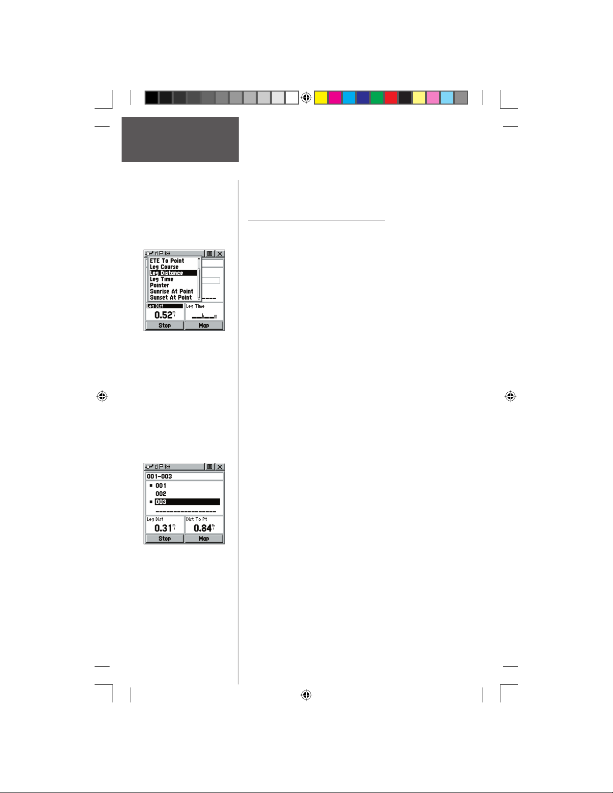
Main Menu Page
Routes
Data Field Options Menu
To stop navigation:
1. Highlight the ‘Stop Navigation’ option on either the
Navigation or Map page’s Options Menu or select
the ‘Stop’ button on the Route Page.
Data Fields for the Route Page
When navigating a Route, the data displayed in the
data fi elds on the Route Page may be customized to
provide useful navigation information that is specifi cally
related to route navigation.
Data options (for Route Page only) include:
Distance to Point - The distance from your current
location to a route waypoint.
ETA To Point - Estimated Time of Arrival at a route
waypoint (in sequence).
ETE To Point - Estimated Time Enroute to a route
waypoint.
Leg Course - The line of travel between two route
waypoints.
Leg Distance - The distance between two route
waypoints.
Leg Time - The time required to travel from a route
waypoint to the next.
Pointer - Direction pointer to a route waypoint.
Sunrise At Point - Time of sunrise at a route
waypoint.
Sunset At Point - Time of sunset at a route
waypoint.
Preliminary
Distance to Point vs Leg
Distance. To view Leg
information, highlight the
end waypoint on a leg.
To select data fi eld options:
1. Use the CLICK STICK to highlight a data fi eld on
the Route Page and then press IN to display the
Data Field Options Menu.
2. Use the CLICK STICK to highlight the desired
option and then press IN to enter the option in the
data fi eld.
44
190-00284-00_Prelim_FCC.indd 44 9/18/2003, 3:51:20 PM
Page 55
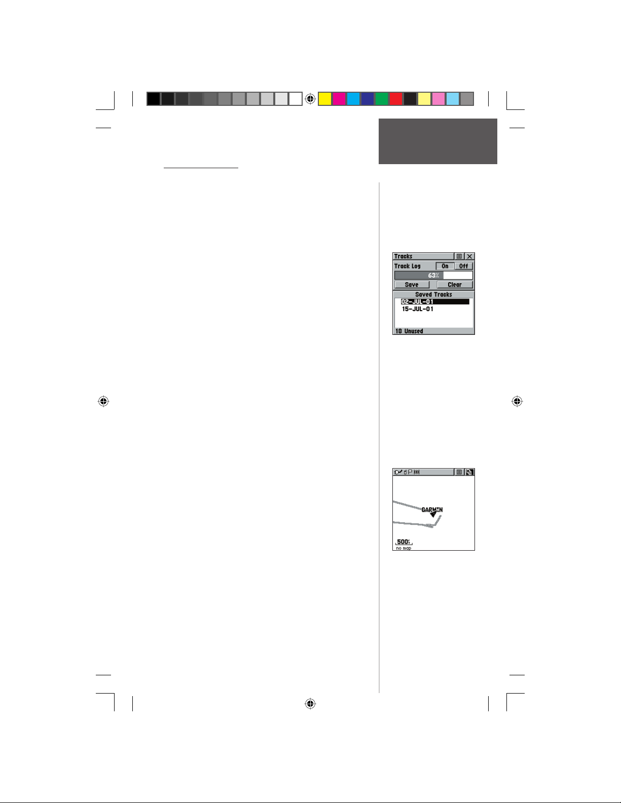
Using Track Logs
The Rino draws an electronic bread crumb trail on the
Map Page as you travel along. This bread crumb trail is
the ‘Track Log’. The Track Log contains information about
points along its path, including time, and position. The
Rino uses this information to allow you to navigate using
the saved track. You may also save tracks from other Rino
users as they communicate with you.
The ‘TracBack’ feature allows you to return along a
traveled path without marking any waypoints. When you
are ready to return to where you started, the Rino takes you
back by following the ‘Track Log’ that you left behind. You
can save a total of 20 tracks in the unit memory. The Track
Log starts recording as soon as the unit gets a satellite location fi x and the Track Log feature is turned on. When you
no longer need a Track Log you can press the on-screen
‘Clear’ button to remove it.
If you want to keep a record of a certain track log or
use the ‘TracBack’ feature, it is recommended that you clear
the Track Log before you start traveling. The percentage of
memory used by the current track log is displayed in a window at the top of the page. After the Track Log is ‘Cleared’,
it displays zero percent. When the display reaches 100%,
the most recent track points start to overwrite the least
recent if the default setting ‘Wrap When Full’ remains
selected on the track log setup. To avoid losing track points
you want, save the Track Log when it approaches the 99%
mark. The active track log will store up to 3000 points.
The Saved Track Page displays the track and it can also
be displayed on the Main Map Page as you navigate. You
may save up to 20 tracks with 250 points per track in the
unit. Saved Contact tracks count towards this total.
The ‘TracBack’ feature allows you to retrace your track
(or another Rino user’s track) in both directions. Tracks are
marked BEGIN and END.
You can set the track recording interval to Distance,
Time, or Automatic. You can set the Track display resolution to High, Medium, Low, and Lowest. You can also use
the Options Menu to delete all saved tracks.
Preliminary
Main Menu Page
Tracks Page
Tracks Page
Track on Main Map Page
For effective use of the
“TracBack” feature, clear
the Track Log before
starting a new trip or after
saving the Track Log.
Rename saved Track Logs
to help identify them later.
45
190-00284-00_Prelim_FCC.indd 45 9/18/2003, 3:51:20 PM
Page 56
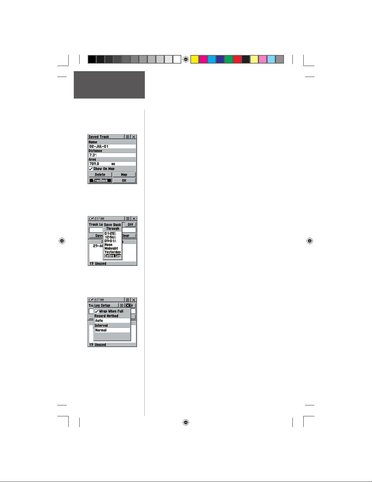
Main Menu Page
Tracks Page
Saved Track Page
Save Track Options
To save and use a Track Log:
1. Access the ‘Tracks’ page from the Main Menu. The
page has On/Off buttons, a list of tracks, and the
number of unused tracks.
2. You can press IN on the on-screen ‘Off’ button to
pause track logging. When track logging is active
the ‘On’ button appears to be recessed.
3. Highlight the ‘Save’ on-screen button and then
press the CLICK STICK to display the track log
‘Save Back Through’ list.
4. Use the CLICK STICK to select the time and date
that you would like to save the track through.
5. Press IN on the CLICK STICK to save the track log
and display the Track Page.
The Track Page shows the track name (which can
be renamed using the keyboard for data entry), the
total distance of the track, track area (if available),
a ‘Show on Map’ option, and on-screen buttons for
‘Map’, ‘OK’, and ‘Tracback’.
6. To enable the Tracback feature, highlight the
‘Tracback’ button and then press IN on the
CLICK STICK. This displays the Tracback Menu
with two options, ‘To Beginning’ and ‘To End’.
Highlight the desired option and then press IN on
the CLICK STICK to enable. Access the Map Page
or the Navigation Page to navigate the Track.
To use Track Log Setup options:
1. Highlight the Tracks Page Options Menu button
at the top of the page and press IN on the
Preliminary
Track Log Setup Menu
If you choose Auto-record, you
can set the recording interval
from More to Least Often. You
can set recording intervals for
Time or Distance as desired.
CLICK STICK to display the menu.
2. Highlight the ‘Tracks Log Setup’ option and then
press IN on the CLICK STICK.
You can check the ‘Wrap When Full’ option
by highlighting it and then pressing IN on the
CLICK STICK. You can highlight the ‘Record
Method’ and ‘Interval’ fi elds and press IN on the
CLICK STICK to display their options. ‘Interval’
options change to accommodate the ‘Record
Method’ choices.
46
190-00284-00_Prelim_FCC.indd 46 9/18/2003, 3:51:21 PM
Page 57
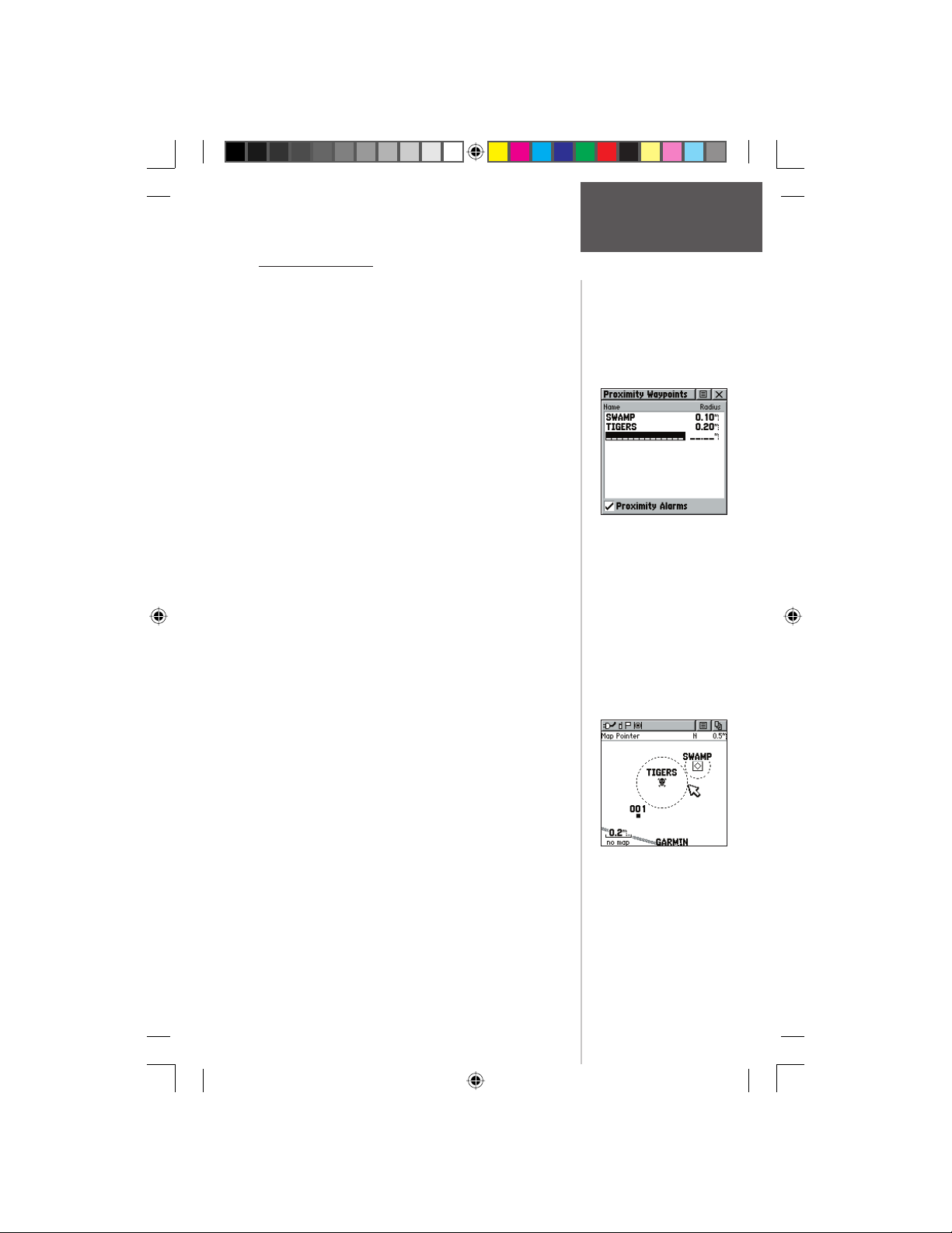
Proximity Points
The Proximity list lets you defi ne an alarm circle
around a stored waypoint/contact position, and can
be used to help you avoid dangerous areas or to alert
you when you have strayed away too far from other
Rino users. Up to ten waypoints may be listed, with
a maximum alarm radius of 99.99 nautical or statute
miles or kilometers. If entering a proximity alarm circle,
a ‘Near Proximity Point <name>’ message will appear.
If leaving a proximity alarm circle, a ‘Leaving Proximity
Point <name>’ message will appear. This option is handy
in case you wish to remain a certain radio distance from
another user.
To add a proximity
1. Use the CLICK STICK to highlight an empty space
on the Proximity list and press IN on the CLICK
STICK. The ‘Find ‘N Go’ screen appears. Highlight
‘Waypoints’ or ‘Contacts’ and press IN on the
CLICK STICK. (You may also select from other
items listed on the ‘Find ‘N Go’ screen.)
2. From the Review Page, highlight ‘Use’ and press the
CLICK STICK IN to confi rm. The distance fi eld will
now be highlighted. Press IN again to begin entry of
the proximity radius.
3. Use the CLICK STICK keys to enter a distance
value (to 99.99 units) and press IN.
waypoint:
Main Menu Page
Proximity Page
Proximity Page
To turn proximity alarms on or off:
1. Use the CLICK STICK to highlight the fi eld left of
“Proximity Alarm” and press IN to place a check.
Preliminary
To clear one or all proximity point(s) from
the list:
1. Use the CLICK STICK to highlight the proximity
point to clear.
2. To clear a single alarm, press IN and choose
‘Remove’ and press IN.
3. To clear all proximity waypoints, highlight the
Options Menu and press IN. Choose ‘Remove All’
and press IN on the CLICK STICK.
4. Use the CLICK STICK to highlight the ‘OK’ prompt
and press IN to confi rm.
190-00284-00_Prelim_FCC.indd 47 9/18/2003, 3:51:22 PM
Proximity Circles on
Map Page
47
Page 58
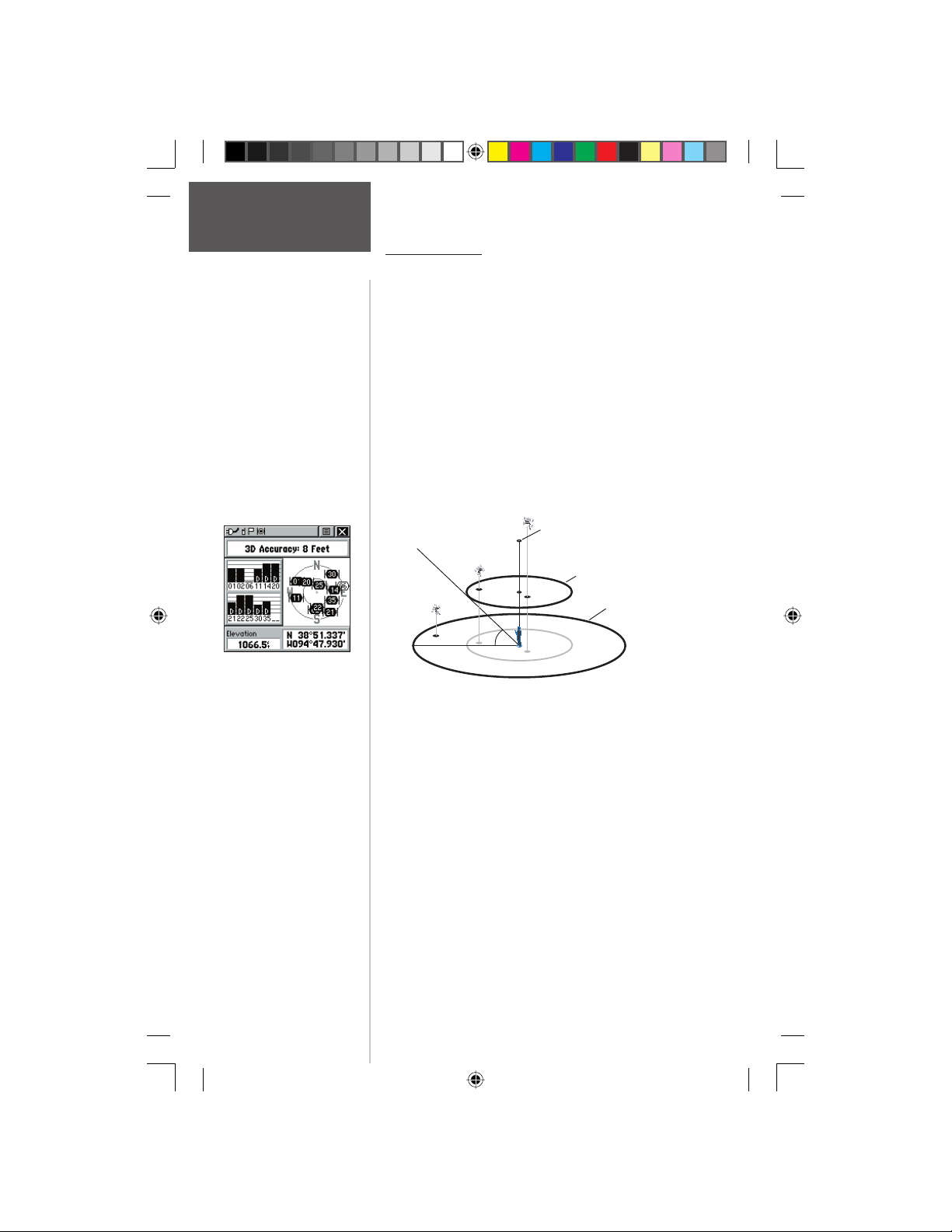
Main Menu Page
Satellite Page
Satellite Page using WAAS.
Preliminary
48
Satellite Page
The Satellite Page provides a picture of satellite signal
tracking, tells you when the unit is ready for navigation,
and shows your location coordinates.
The Skyview graphic represents a view looking up
at the sky from your current location showing satellites
and their assigned numbers. The outer ring represents
the horizon around you, the inner ring represents a view
above you at a 45° angle from vertical, and the center
represents directly overhead. Signal Strength Bars for each
satellite are shown to the left of the Skyview. Satellites
and their signals appear as hollow shapes until a signal is
received and then they appear darkened in. The stronger
the signal, the taller the signal bar.
Center dot - 90°
above the horizon
90°
Inner ring- 45°
above the horizon
Outer ring the horizon
45°
The Wide Area Augmentation System (WAAS)
capability produces a more accurate position fi x. When
enabled (the GPS mode set to ‘Normal’ and the interface
set to other than RTCM mode), this feature searches for
a WAAS satellite near your location and then receives
data for correcting differentials in the GPS satellite signals
and the WAAS satellite numbers (beginning at No. 33 or
above) display on the Satellite Page. When differential
correction data has been received for GPS satellites (numbers 32 or below), a ‘D’ displays in the signal bar beneath
the skyview. It is helpful to orient the unit antenna toward
the WAAS satellite shown in the skyview. To learn more
about the WAAS System, access the Federal Aviation
Administration web site (http://gps.faa.gov/). Because the
Rino relies on satellite signals to provide you with navigational guidance, the unit’s view of the sky determines how
fast you achieve navigational status. GPS signals do not
190-00284-00_Prelim_FCC.indd 48 9/18/2003, 3:51:23 PM
Page 59
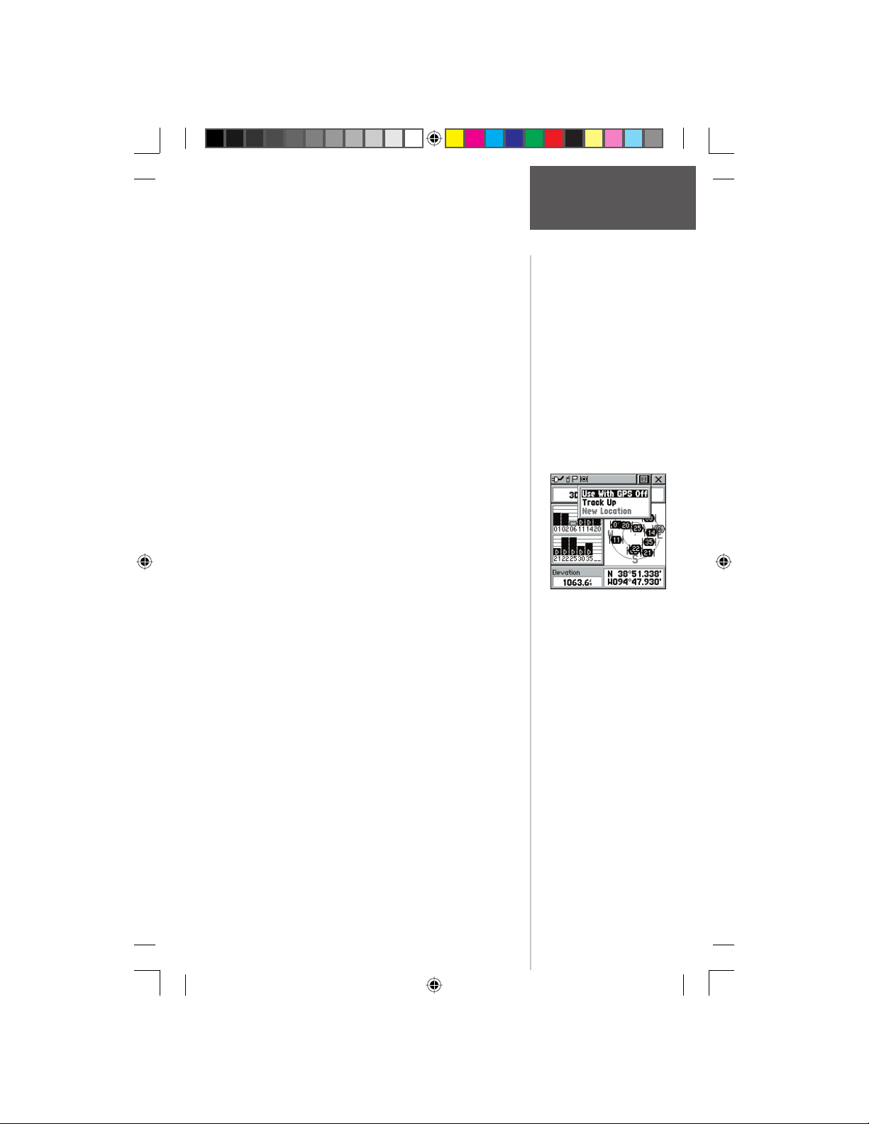
travel through rocks, buildings, people, metal, or heavy
tree cover so for best results, keep the unit in clear view
of the sky.
At least three satellite signals are needed to determine
your location, otherwise the unit displays a “Poor Satellite
Reception” message with four options and a brief explanation to guide your decision:
Use with GPS Off - Select this option if you want
GPS off.
New Location - Select this option if you have moved
more than 600 hundred miles (from where you last
used the unit).
Restart Search - Select this option if today is not
(date provided).
Continue Acquiring - Select this option if no other
option applies. (The unit will attempt to gather GPS
signals.)
The Satellite Page options include:
Use With GPS Off - Use this option when you are
indoors, a clear view of the sky is obstructed, or you
want to save battery power. You can enter data, create
routes, etc., but cannot navigate in this mode.
Track Up/North Up - You can orient the satellite
skyview by selecting ‘Track Up’ (your direction of
travel) or ‘North Up’ (the satellite skyview oriented to
the north).
New Location - If you are more than 600 miles (from
where you last used the unit), select the ‘New Loca-
tion’ and then the ‘Use Map’ options to approximate
your location. This gives the unit reference informa-
tion and speeds satellite acquisition.
Preliminary
Main Menu Page
Satellite Page
Satellite Page Options Menu
Highlight the on-screen button
at the top of the page & press
in on the CLICK STICK.
190-00284-00_Prelim_FCC.indd 49 9/18/2003, 3:51:24 PM
49
Page 60
Main Menu Page
Satellite Page
Preliminary
To select the ‘Use With GPS Off’ option:
1. Use the CLICK STICK to highlight the Option Menu
button at the top of the page and then press it IN to
display the Options Menu.
2. Use the CLICK STICK to highlight the ‘Use With
GPS Off’ option and then press it IN to activate.
The Rino stops tracking satellites and should not
be used for navigation. However, the next time you
turn the unit on, it returns to Normal GPS operation.
To select ‘Track Up’ or ‘North Up’:
1. Use the CLICK STICK to highlight the Option Menu
button at the top of the page and then press it IN to
display the Options Menu.
2. Highlight either the ‘Track Up’ or ‘North Up’ option
(depending on which is currently in use), and press
in on the CLICK STICK to activate.
To enter a new location:
1. Use the CLICK STICK to highlight the Option Menu
button at the top of the page and then press it IN to
display the Options Menu.
2. Highlight ‘New Location’ and press in on the
CLICK STICK to display choices of ‘Auto’ or ‘Use
Map’.
If you choose ‘Auto’ the Rino determines your new
location automatically.
If you choose ‘Use Map’ a map page displays with
instructions stating, “Point to your approximate
location and press ENTER”. Use the CLICK STICK
to move the map pointer to your location on the
map and press it IN.
50
190-00284-00_Prelim_FCC.indd 50 9/18/2003, 3:51:24 PM
Page 61
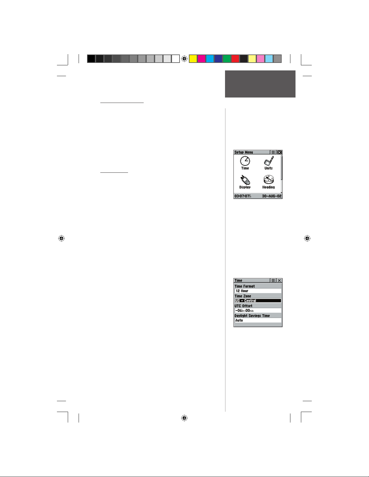
The Setup Menu
The Setup Pages allow you to customize your Rino to
your personal preferences. You can choose time settings,
units of measure, display backlighting and contrast settings, heading measurement, interface options and system
operating mode.
By highlighting the icons on the Setup Menu and then
pressing in on the CLICK STICK, you can display the
Setup Page for each of the menu items.
Time Page
You can set the time to match your location or for a
projected location anywhere in the world.
Time Format - Allows you to choose from 12 or 24
hour time format so the clock displays like a standard
clock with 12-hour AM and PM cycles or display a 24hour cycle (Military Time).
Time Zone - Can be set to one of the eight US Time
Zones, or 24 International Time Zones (nearest city or
geographical region). Select ‘Other’ so you can enter the
UTC Time Offset.
Daylight Savings Time - Can be turned On or Off or
set to Automatic.
Main Menu Page
Setup Page
Setup Menu
To set the time:
1. Use the PAGE button to access the Main Menu.
2. Use the CLICK STICK to highlight the Setup Icon
and then press it IN to display the Setup Menu.
3. Use the CLICK STICK to highlight the Time Icon
4. Use the CLICK STICK to highlight the ‘Time Zone’
5. Highlight a time zone from the list and then press
6. If you choose ‘Other’, you must enter a UTC offset
7. The correct time displays at the bottom of the page.
190-00284-00_Prelim_FCC.indd 51 9/18/2003, 3:51:25 PM
Preliminary
and then press it IN to display the Time Page.
fi eld then press it IN to display the time zone list.
IN on the CLICK STICK.
value.
Time Setup Page
51
Page 62
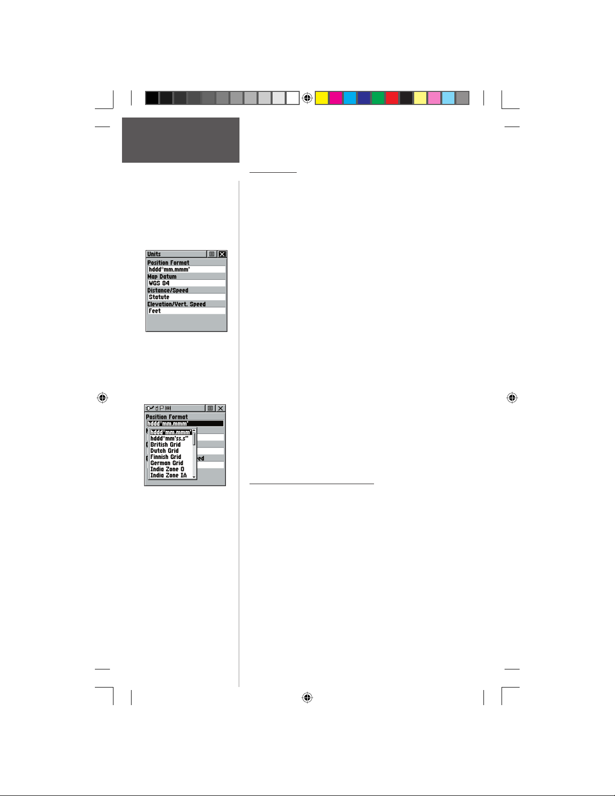
Main Menu Page
Setup Page
Units Page
Units Page
The Units features are best used by individuals with
a working knowledge of map grids and datums. To learn
more about these subjects, visit the National Imagery and
Mapping Agency at http://www.nima.mil or inquire at
your local library.
To select Units Page options:
1. For all fi elds on this page, highlight the fi eld and
then press the CLICK STICK to display the Options
Menu for the fi eld.
2. Highlight the desired option on the menu and then
press the CLICK STICK to place it in the fi eld.
Position Format - Allows you to choose from
different grid formats. The default position format,
‘hddd°mm.mmm’ displays the latitude and longitude in
degrees and minutes and is most commonly used.The
following additional formats are available:
hddd.ddddd°— latitude/longitude in decimal degrees
only, hddd°mm’ss.s”— latitude/longitude in degrees,
minutes, seconds, UTM/UPS— Universal Transverse
Mercator / Universal Polar Stereographic grids, British
Grid, Dutch Grid, Finnish KKJ27, German Grid, India
Zones, Irish Grid, Loran TD, Maidenhead, MGRS, New
Zealand, Qatar Grid, RT90, Swedish Grid, Swiss Grid,
Taiwan Grid, User Grid, W Malayan RSO
Using the LORAN TD Format
Position Format
Options Menu
Preliminary
When creating new waypoints using LORAN TD
coordinates, you must set the correct LORAN chain number and secondary stations in the Setup TD fi eld before
storing the waypoint. After the waypoint is stored in unit
memory, it will always reference the LORAN chain num-
The ‘User’ datum is based on
a WGS-84-Local datum and
is an advanced feature for
unlisted or custom datums. To
learn more, check your local
library or on the world wide
web for educational materials
on datums and coordinate
systems.
ber and secondary stations currently selected in the Setup
TD fi eld. If you enter a different LORAN chain number,
change the secondary stations or offsets in the Setup TD
fi eld, the active waypoint information will refl ect those
changes. Since the GPSMAP unit does not rely on the
LORAN signal for navigation, it can reference a different
GRI chain and/or secondary stations and still navigate to
the location stored in memory.
52
190-00284-00_Prelim_FCC.indd 52 9/18/2003, 3:51:26 PM
Page 63
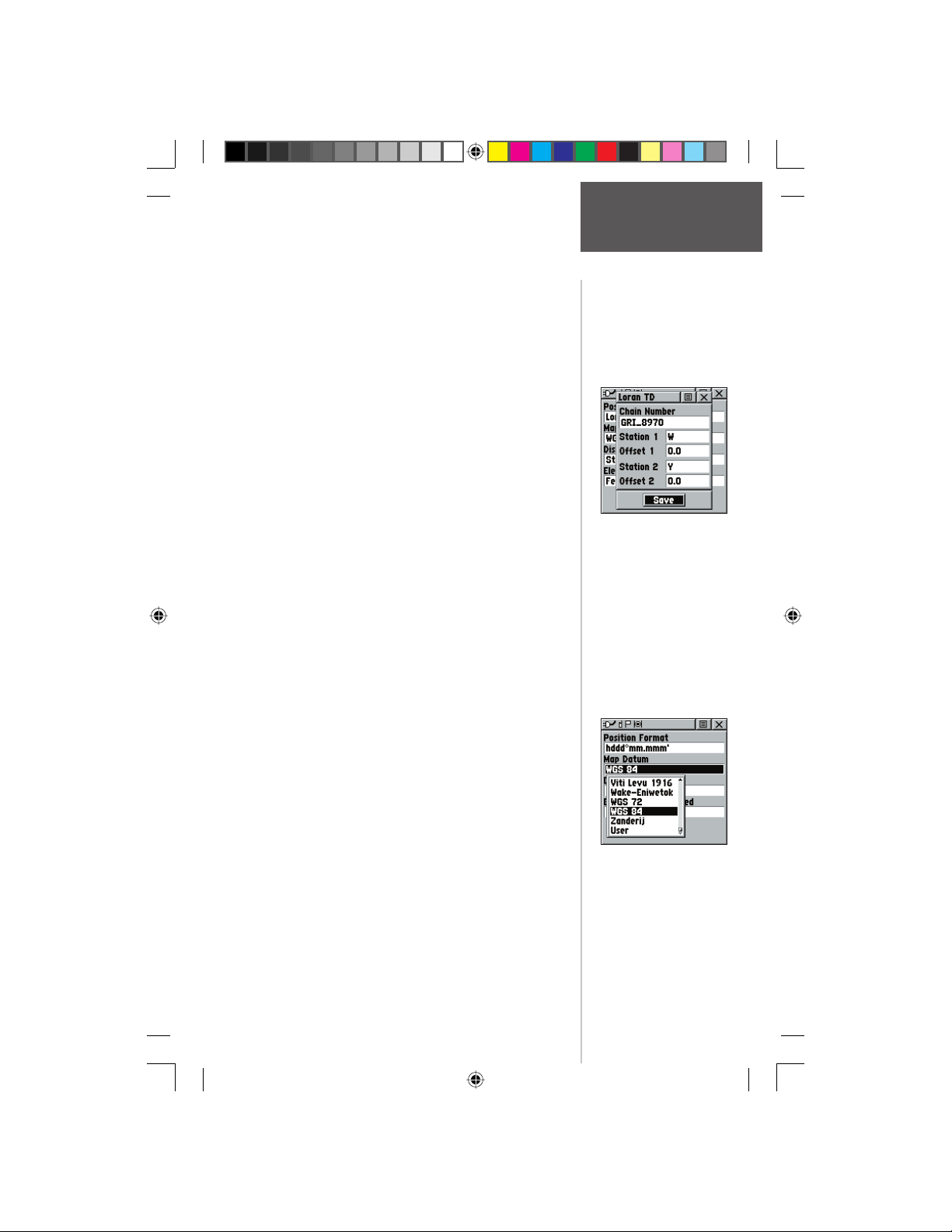
Main Menu Page
To setup Loran TD from the Main Menu:
1. When ‘Loran TD’ is chosen, the Loran TD setup
window will automatically appear.
2. To change the settings of any of the fi ve fi elds,
highlight the fi eld, press the CLICK STICK IN.
3. When done, highlight ‘Save’ and press IN.
4. To return to the setup page, simply select Loran TD
from the Position Format fi eld again..
If the active GRI Chain, secondary stations or offsets
have been changed since the waypoint was created, the
waypoint will now reference the active GRI chain and
secondary stations and adjust the TD coordinates accordingly. Remember that the GPS is not relying on the
LORAN signal for navigation and actually converts the TD
coordinate to a useful LAT/LON coordinate (in the background) before storing the waypoint to memory or using
it for navigation. Because of this the unit can navigate to a
TD coordinate anywhere in the world.
For more information on Loran TDs, you may download Garmin’s “Loran TD Position Format Handbook”
from the Garmin web site at http://www.Garmin.com/
support/userManual.html.
Map Datum - Offers a selection of nearly all map
datums in common use. Every map is based on a map datum (a reference model of the earth’s shape) and is usually
listed in the title block of the map. If you are comparing
GPS coordinates to a paper map, chart, or other reference,
the map datum in this fi eld must match the horizontal
map datum used to generate the map or other reference.
The default datum is WGS 84 (World Geodetic Survey
1984) and should only be changed when using maps or
charts specifying a different datum. If a map does specify
a datum, use the options list to fi nd datums applicable to
the region of the map, selecting the one that provides the
best positioning at a known point. If necessary, you also
may choose the ‘User’ datum for custom designed grids.
Distance/Speed - You can choose from three units of
measure to display your rate of travel.
Elevation/Vertical Speed - You can choose from two
units of measure to record your elevation and vertical
speed.
Preliminary
Setting Loran TD Info
Setup Page
Map Datum
Options Menu
53
190-00284-00_Prelim_FCC.indd 53 9/18/2003, 3:51:26 PM
Page 64
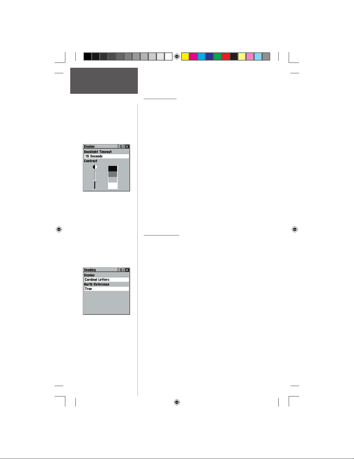
Main Menu Page
Setup Page
Display Page
You can adjust the amount of time that the backlight-
ing feature stays on and adjust the screen contrast.
Backlighting Timeout - Choose from Stays On, to
delays of 15 seconds, 30 seconds, one, or two minutes
before timing out.
Contrast Adjustment - Can be adjusted from light to
dark using the slider adjacent to the contrast bar.
To set the backlighting timeout:
1. Highlight the Backlight Timeout fi eld and then press
IN on the CLICK STICK to display options.
2. Highlight the desired option and then press IN on
the CLICK STICK to activate it.
Display Page
Preliminary
Heading Page
To adjust the contrast:
1. Highlight the contrast slider and then press IN on
the CLICK STICK to activate.
2. Move the CLICK STICK up or down to move the
slider until the desired contrast has been set.
Heading Page
You can select the type of heading displays, the types
of North References, or enter the magnetic variation.
Display - Allows you to choose from Cardinal Letters,
Degrees or Mils.
North Reference - You can choose from True,
Magnetic, Grid or User options. If ‘User’ is chosen, you
must correct for the Magnetic Variation. The Electronic or
GPS compass uses the North Reference setting to create a
bearing.
To select either option:
1. Highlight the fi eld and then press IN on the
CLICK STICK to display the options.
2. Highlight the option and press IN on the
CLICK STICK to activate.
54
190-00284-00_Prelim_FCC.indd 54 9/18/2003, 3:51:27 PM
Page 65
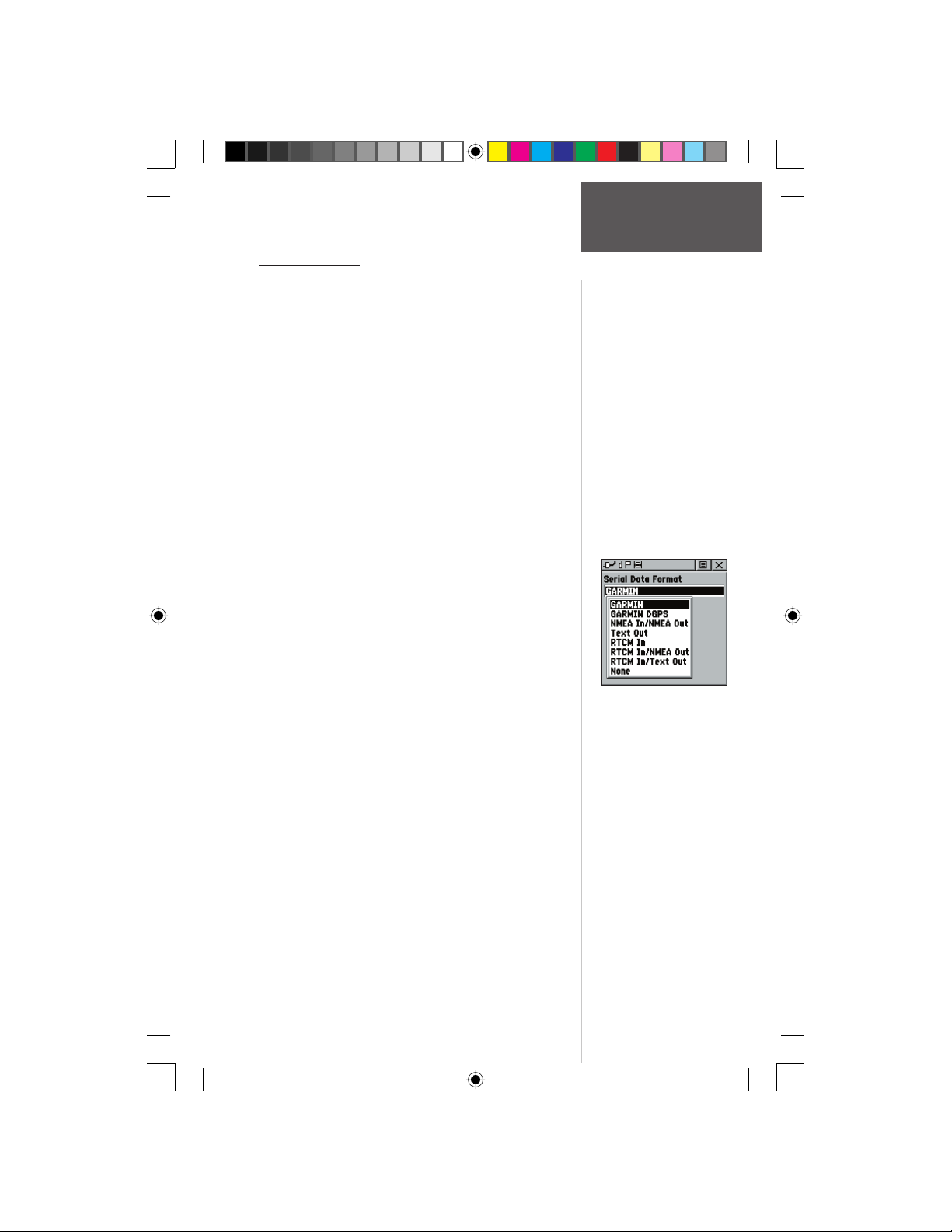
Main Menu Page
Interface Page
The Interface Settings Page allows you to choose from
different input/output serial data formats. This feature is
used when connecting to external NMEA devices, a DGPS
beacon receiver, a personal computer, etc. See page 68 for
using the Rino with MapSource. The formats are: formats:
Garmin - The proprietary format used to exchange
waypoint, track, and map data with a PC. Use this setting
for transferring data when using a MapSource product.
Garmin DGPS - Allows DGPS input using a Garmin
beacon receiver and a standard RTCM SC-104 and DGPS
tuning.
NMEA In/NMEA Out - Supports the output of standard
NMEA 0183 version 3.0 data. Use this for real-time plotting with MapSource or 3rd party programs.
Text Out - Allows ASCII text output of location and velocity information without input capabilities.
RTCM In - Allows DGPS input using a standard RTCM SC-104 format without output capabilities.
RTCM In/NMEA Out- Allows DGPS input using a
standard RTCM SC-104 format and supports the output of
standard NMEA 0183 version 3.0 data.
RTCM In/Text Out- Allows DGPS input using a standard
RTCM SC-104 format and simple ASCII text output of
location and velocity information.
None - Provides no interfacing capabilities.
If ‘Garmin DGPS’ or ‘RTCM in/NMEA Out’ format is
selected, additional fi elds are provided to control a Garmin
differential beacon receiver (e.g. GBR 21 & GBR 23)
directly from your unit. Tuning is automatic with ‘Scan’
or you can enter the beacon frequency and bit rate when
you select ‘User’ from the Beacon list to manually tune the
receiver. Refer to the beacon receiver instructions.
Preliminary
Setup Page
Serial Data Options
To select a serial data format:
1. Highlight the Serial Data Format fi eld and then press
IN on the CLICK STICK to display options.
2. Highlight an option and then press IN on the
CLICK STICK to activate it.
190-00284-00_Prelim_FCC.indd 55 9/18/2003, 3:51:28 PM
55
Page 66
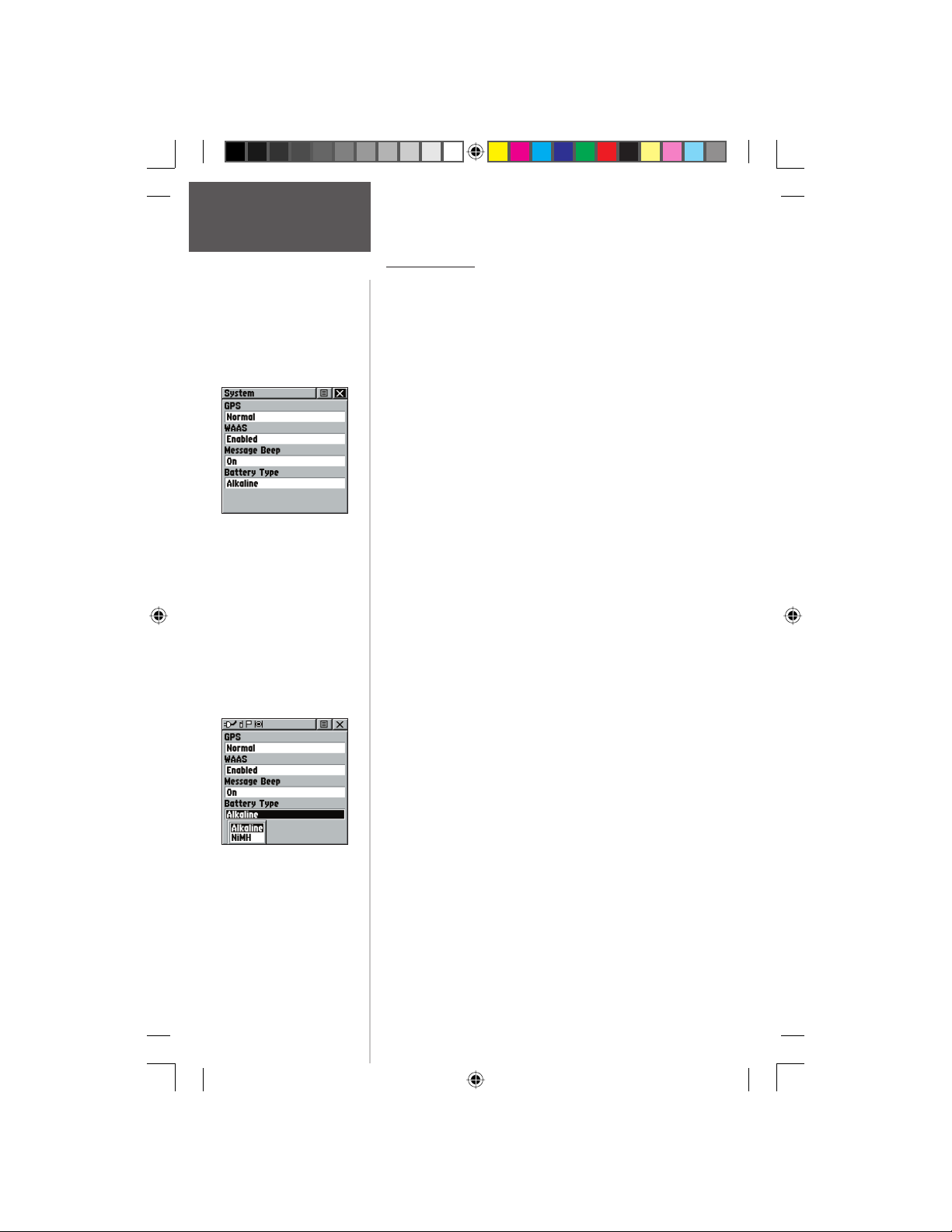
Main Menu Page
Setup Page
System Setup Page in
Normal Mode,
WAAS Enabled.
System Page
The System Setup Page allows you to change GPS
operation modes, use the WAAS capabilities, and turn the
Message Beep on or off and choose the battery type.
The Option Menu allows you restore defaults or
display the current version of unit operating software and
the Unit I.D. Number. Software updates and instructions
for downloading are available from the Garmin web site
(www.Garmin.com).
Choose one of the four GPS options other than
‘Normal’ to signifi cantly save battery power. The ‘Battery
Saver’ mode reduces the rate of satellite signal position updating and the ‘GPS Off’ option stops satellite
signal reception altogether. The ‘Demo Mode’ simulates
navigation.
See page 48 for an explanation of WAAS capabilities.
To adjust System Page options:
1. Use the CLICK STICK to highlight the fi eld and
then press IN to display options. Then use the
CLICK STICK to select the desired option and press
IN.
To display Software Version and Unit ID:
1. Use the CLICK STICK to highlight the Options
Menu and then press IN. Then use the CLICK STICK
to highlight ‘Software Version’ and press IN. Press IN
again to close that Software Version window.
To change Battery Type:
Preliminary
Advertised battery life
is rated using Alkaline
batteries. You may not get
the listed battery life using
other types of batteries.
1. Use the CLICK STICK to highlight the ‘Battery Type’
fi eld and then press IN. Then use the CLICK STICK
to select the desired option and press IN.
Use the following settings for different battery types:
Battery Type Set Unit To
Alkaline Alkaline
NiMH NiMH
NiCad NiMH
Lithium (1.2V) NiMH
Lithium (1.5V) Alkaline
56
190-00284-00_Prelim_FCC.indd 56 9/18/2003, 3:51:28 PM
Page 67
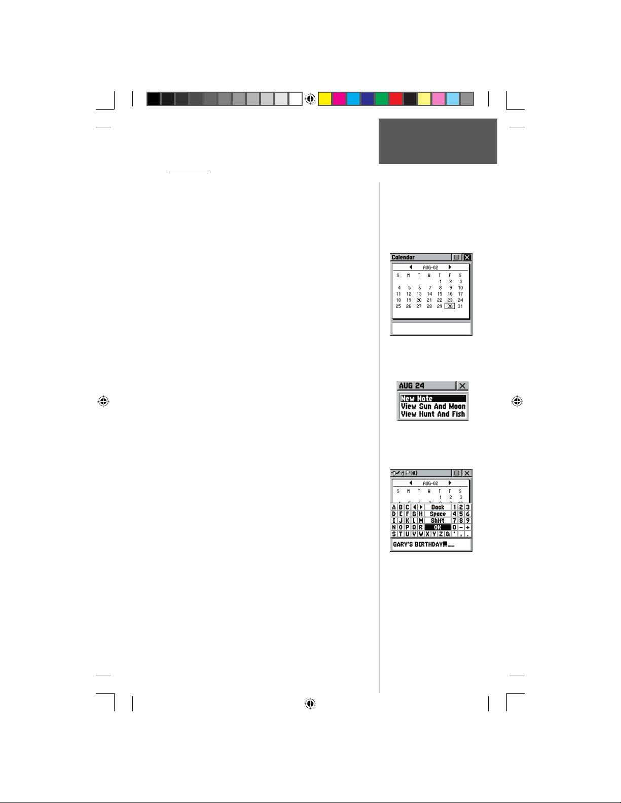
Main Menu Page
Calendar
This feature provides you with a monthly calendar
with programmable reference notes dates. You can display
one monthly calendar of days at a time and mark days on
each with reference notes using the data entry keypad.
Days that are shaded have notes added. You can create
reference notes for multiple months and for months in
years yet to come. You can record 100 notes with up to
18 characters each.
To change the month and year:
1. Highlight the left or right arrows on either side
of the date and press IN on the CLICK STICK to
change the month/year. The left arrow will show
past months/years and the right arrow will show
future months/years.
To use the current month and year:
1. Choose ‘Set To Current Date’ from the Options
Menu.
To create a reference note for a selected
date:
1. Use the CLICK STICK to highlight the day of the
month and then press IN to display the Options
Menu for the date.
2. Highlight and select ‘New Note’ to begin entering
text from the keyboard.
Observe the message as it is created in the message
block below the keyboard.
3. To edit or delete a note previously created, highlight
Preliminary
the date and press IN on the CLICK STICK. Options
shown include ‘Edit Note’, ‘Delete Note’, ‘View Sun
and Moon’, or ‘View Hunt and Fish’.
Calendar
Calendar Page
Calendar Page Options
To delete notes by week:
1. Choose ‘Delete Notes...’ from the Options Menu.
2. From the ‘Oler Than..’ window, choose the desired
option and press IN on the CLICK STICK.
190-00284-00_Prelim_FCC.indd 57 9/18/2003, 3:51:29 PM
Calendar Page Keyboard
and Message Block
57
Page 68
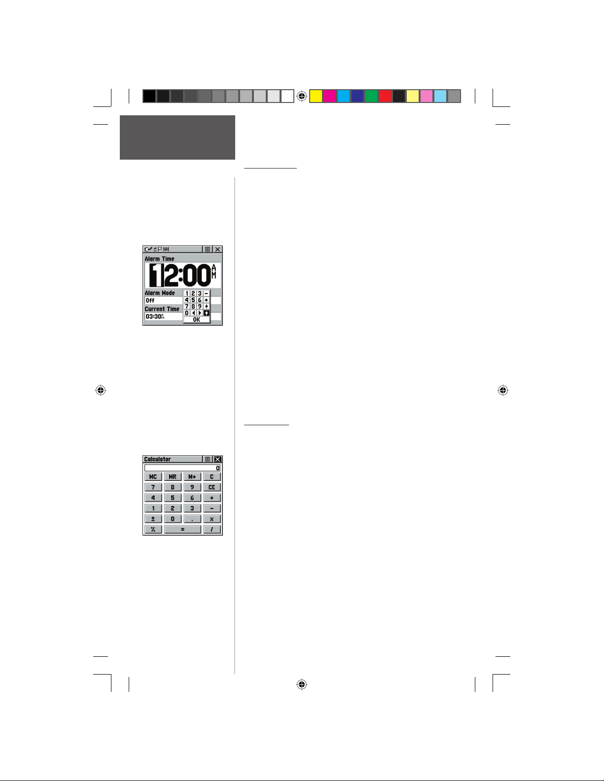
Main Menu Page
Alarm Clock /
Calculator
Alarm Clock Page
Preliminary
Calculator Page
Alarm Clock
This feature provides an alarm for the system clock.
Enter a time in the time fi eld and turn the alarm on and
off from the control fi eld menu. Remember to enter alarm
times in the same time format (UTC or local) you’re using
for your system. The unit must be on for the clock alarm
to work.
To set an alarm clock time:
1. Use the CLICK STICK to highlight the time fi eld
and then press IN to display the keyboard. Then use
the CLICK STICK to enter the desired time, choose
‘OK’ and press IN.
To turn the alarm clock On/Off:
1. Use the CLICK STICK to highlight the Alarm Mode
fi eld and then press IN to display the options.
2. Choose ‘On’ or ‘Off’ and press IN on the CLICK
STICK.
When the alarm sounds, a brief tone will be heard
(unless Message Beep is ‘Off’ under System Setup) and
“Alarm Clock” will appear on the screen. Press IN on the
CLICK STICK to acknowledge the alarm.
Calculator
This feature provides you with all the basic functions
of both of standard or scientifi c calculator. You can perform most calculations identifi ed by the function symbols
along the sides of the keypad and can save the results
temporarily in the memory. The memory is cleared either
manually or when you turn off the Rino.
To change calculator options:
1. Highlight the page Options Menu and press IN
on the CLICK STICK to display the ‘Scientifi c/
Standard’ and ‘Radian/Degrees’ options.
2. Highlight the option you want to change and then
press IN on the CLICK STICK for the change to
take effect.
3. Use the CLICK STICK to move about the keypad,
enter numbers, and perform calculations.
58
190-00284-00_Prelim_FCC.indd 58 9/18/2003, 3:51:30 PM
Page 69
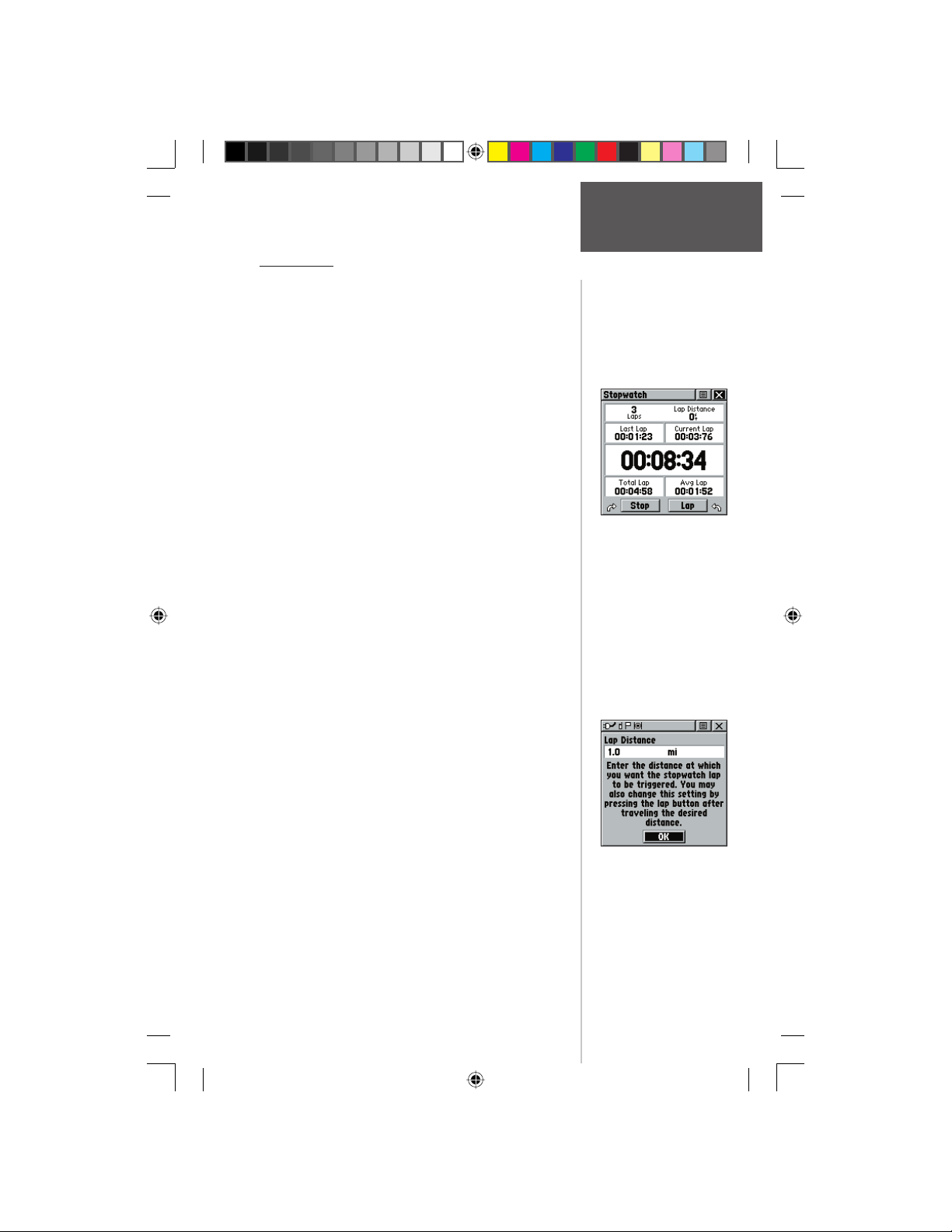
Main Menu Page
Stopwatch
This feature allows you to use the unit as a stopwatch,
including a lap timer. You may also have the unit record
the lap time based on distance. For example, if you set the
lap distance to one mile, the unit will record the time it
takes you to travel one mile.
To start the stopwatch:
1. Use the CLICK STICK to highlight the ‘Start’
fi eld and then press IN. You may also press the V
(Volume) key to Start the stopwatch.
To stop the stopwatch:
1. Use the CLICK STICK to highlight the ‘Stop’
fi eld and then press IN. You may also press the V
(Volume) key to Stop the stopwatch.
To use the lap feature:
1. With the stopwatch running, use the CLICK STICK
to highlight the ‘Lap’ fi eld and then press IN. You
may also press the Z (Zoom) key to capture the lap
time.
To reset the stopwatch:
1. With the stopwatch stopped, use the CLICK STICK
to highlight the ‘Reset’ fi eld and then press IN. You
may also press the Z (Zoom) key to reset the times.
To time lap by distance:
1. Use the CLICK STICK to highlight the Options
Menu and then press IN. Choose ‘Lap by Distance’
and press IN. To return to ‘Lap by Button Press’,
repeat these same steps.
To set a lap distance value:
1. Use the CLICK STICK to highlight the Options
2. Use the CLICK STICK to highlight the fi eld you
Preliminary
Menu and then press IN. Choose ‘Set Lap Distance’
and press IN. To return to ‘Lap by Button Press’,
repeat these same steps.
wish to change and then press IN. Enter the new
value and press IN. When done, highlight ‘OK’ and
press IN on the CLICK STICK.
Setting Lap By Distance
Stopwatch
Stopwatch Page
190-00284-00_Prelim_FCC.indd 59 9/18/2003, 3:51:31 PM
59
Page 70
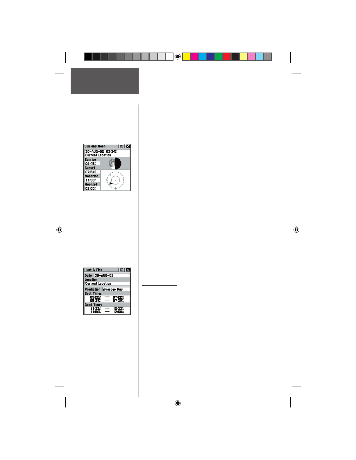
Main Menu Page
Sun and Moon /
Hunt and Fish
Sun and Moon Page
Sun and Moon
This feature provides you with a graphic display of
both sun and moon positioning for a certain date, time
and location with times for sunrise, sunset, moonrise, and
moonset.
To set the date and time:
1. For the Date and Current Time, highlight each fi eld,
then press IN on the CLICK STICK to begin data
entry of individual characters.
2. To display the current date and time, highlight
the page Options Menu and press IN on the
CLICK STICK to display the ‘Use Current Time’
option and then press IN on the CLICK STICK to
activate.
To set the location:
1. Highlight the Location fi eld and then press the
CLICK STICK to display the ‘New Location’ options
list.
2. Highlight the option desired and then press IN on
the CLICK STICK to activate. If you choose ‘Current
Location’ the fi eld values displayed on the page
displays your location. If you choose ‘Use Map’, a
map page displays. Use the map pointer to identify
the desired location and then press IN on the
CLICK STICK. If you choose ‘Use Find ‘N Go Menu’
follow instructions for using the Find ‘N Go Menu on
page 31.
Hunt and Fish
Preliminary
This feature provides you with a listing of best times
for hunting and fi shing for a chosen location and date.
To set the date:
1. Highlight the date fi eld and then press IN on the
Hunt and Fish Page
CLICK STICK to begin data entry of individual
characters. To display the current date, highlight
the page Options Menu and press IN on the
CLICK STICK to display the ‘Use Current Date’
option and then press IN on the CLICK STICK to
activate.
60
190-00284-00_Prelim_FCC.indd 60 9/18/2003, 3:51:31 PM
Page 71
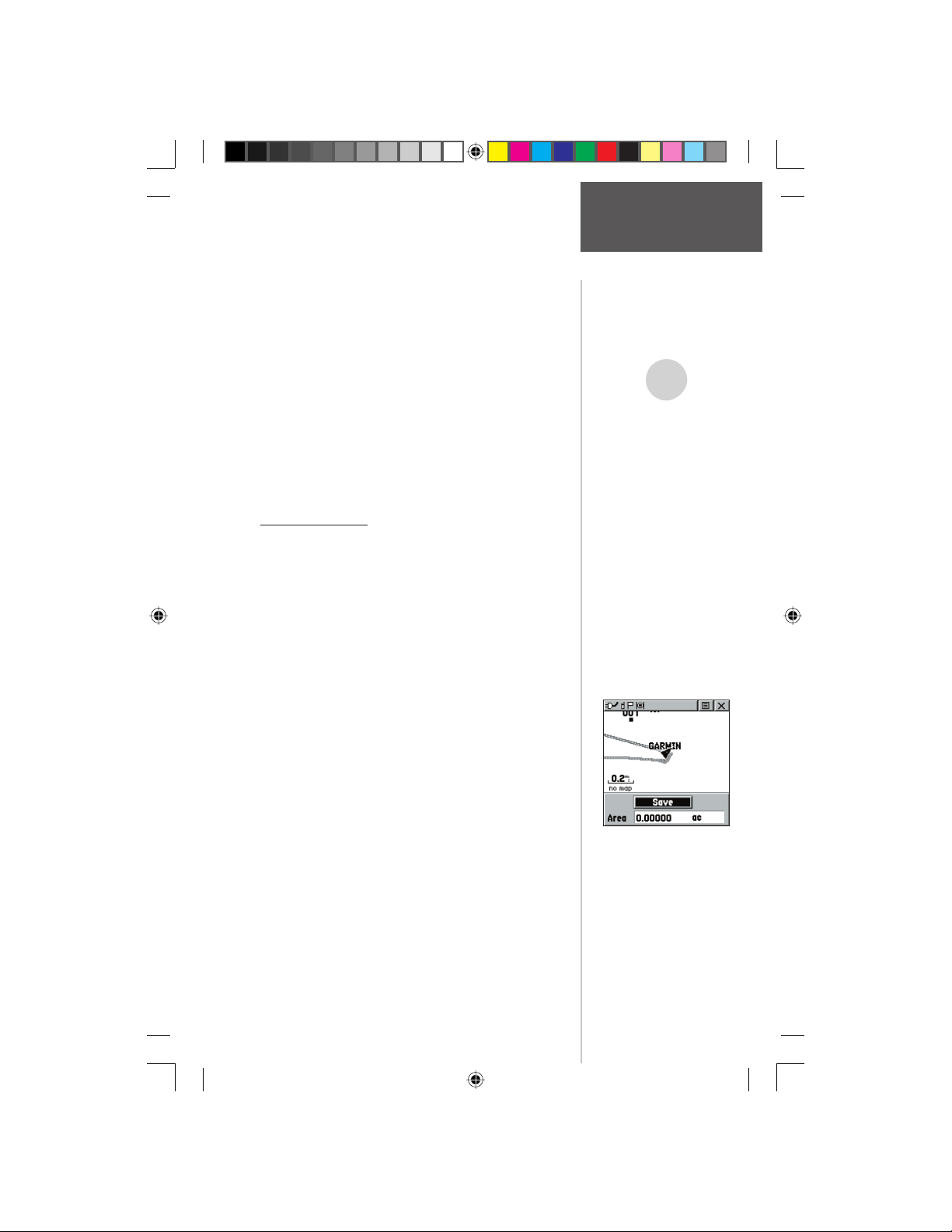
To set the location:
1. Highlight the Location fi eld and then press IN on
the CLICK STICK to display the ‘New Location’
options list.
2. Highlight the option desired and then press IN
on the CLICK STICK to activate. If you choose
‘Current Location’ the fi eld values displayed on the
page refl ect the times at your current location.
3. If you choose ‘Use Map’, a map page displays. Use
the map pointer to identify the desired location and
then press IN on the CLICK STICK.
If you choose ‘Use Find ‘N Go Menu’ follow
instructions for using the Find ‘N Go Menu on page
31.
Area Calculator
This feature provides you an area calculation as you
move about a location or view a saved track. The area
calculation displays in acres, hectares, and square feet,
square yards, square meters, square kilometers, and
square miles.
To calculate the area:
1. With the Rino having a GPS fi x, press ‘Start’ when
you are ready to begin.
2. Begin walking or traveling the outskirts of the area
you want to measure.
3. Continue to the end point, then use the
CLICK STICK to stop the calculation.
4. Use the CLICK STICK to store the area as a saved
track.
Preliminary
To review the area of a saved track:
1. On the Tracks page, highlight a Saved Track and
press IN on the CLICK STICK to see a map with
the area shown in a data fi eld at the bottom.
Main Menu Page
Hunt and Fish /
Area Calculator
,
NOTE: The times displayed
are the recognized best and
good times for hunting and
fi shing. But, be certain that
they are not in confl ict with
state and local game laws
which may vary from location
to location. It is your responsibility to know and abide by
these laws.
‘New Location’ Options
190-00284-00_Prelim_FCC.indd 61 9/18/2003, 3:51:32 PM
61
Page 72
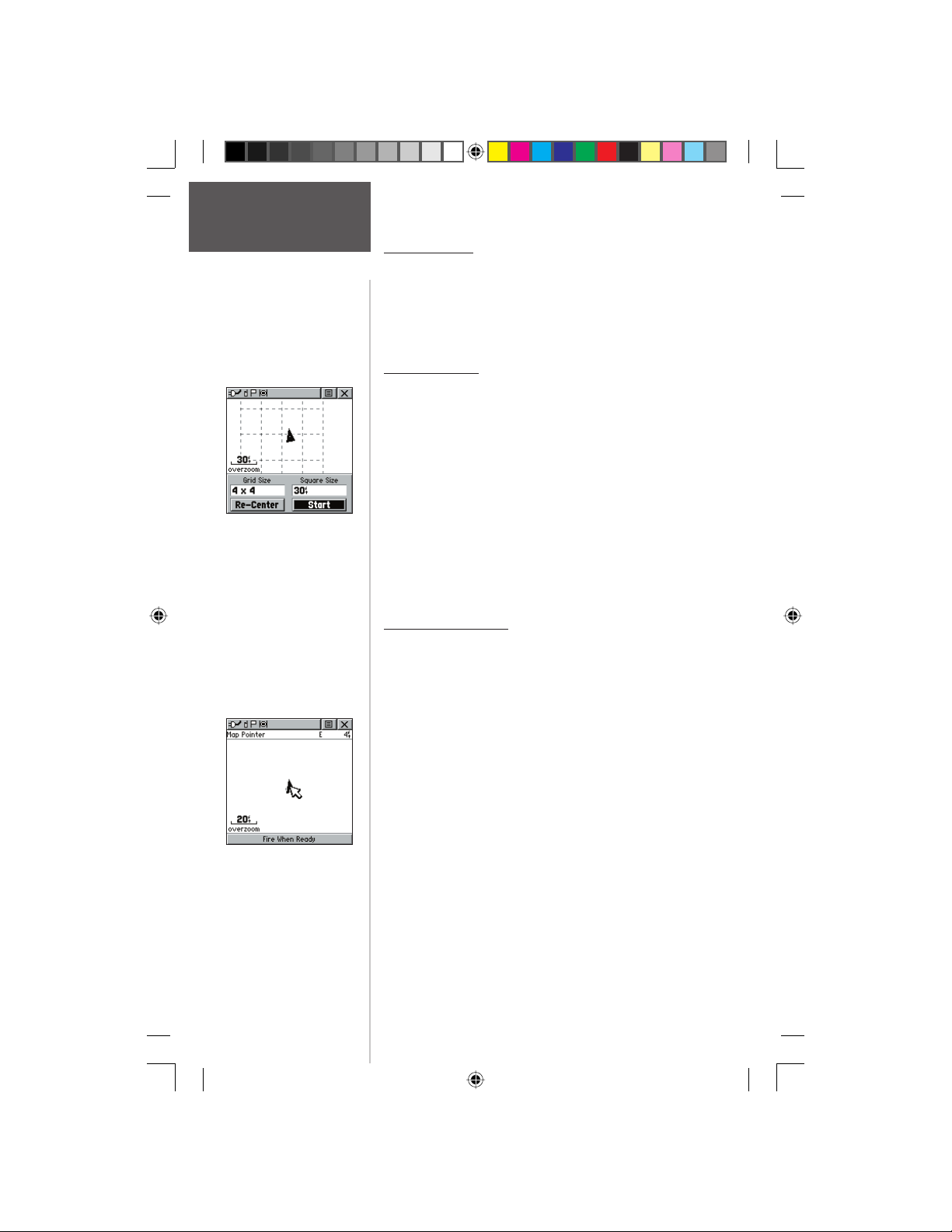
Main Menu Page
Games
Preliminary
62
Games Menu
The Games Page includes: Memory Race, Waypoint
Bomber, Clothesline, Assimilation and Beast Hunt.
Highlight the appropriate icon and then press IN on the
CLICK STICK to play the desired game. Brief instructions
will be displayed when you start each game.
Memory Race
Be the fi rst to clear the board by matching all of the two
symbols sets together. Each symbol is in a square (you can
adjust the size) which you will need to walk or travel to.
Once your position appears in a square, highlight ‘Open’
at the bottom of the screen and press IN on the CLICK
STICK. Play by yourself or race against others! Press PAGE
to quit at any time.
To adjust the Grid Size or Square Size:
1. Highlight the ‘Grid Size’ or Square Size’ fi eld and press
IN on the CLICK STICK.
2. Choose the desired size and press IN. Highlight ‘Start’
and press IN to begin the game!
Waypoint Bomber
In this game, it’s good to stay on the move! Two or more
players attempt to “bomb” each other using their Rino
radios. All players must be on the same channel/code to
play. Move your cursor around on the map page using your
CLICK STICK. When you think an opponent is close to
the cursor, drop a bomb by press IN on the CLICK STICK.
The receiving radio will show an ‘Incoming” message. If
the receiving radio is within the blast circle (about 45 feet),
it will display a message that you have been hit. You must
wait 10 seconds during shots to reload. You could play
to the fi rst player with so many hits loses or have a timed
game with the winner being the one with the least amount
of hits on their radio! Hint: Mark stationary objects such as
trees, poles etc and drop a bomb when an opposing player
is near that object! Adjust the rules to your liking!
1. To fi re at the cursor location, press Enter (IN on the
CLICK STICK
2. To fi re at your current location, press the TALK key.
3. Press CALL to view the scoreboard at any time.
4. Press PAGE to quit the game at any time.
190-00284-00_Prelim_FCC.indd 62 9/18/2003, 3:51:33 PM
Page 73
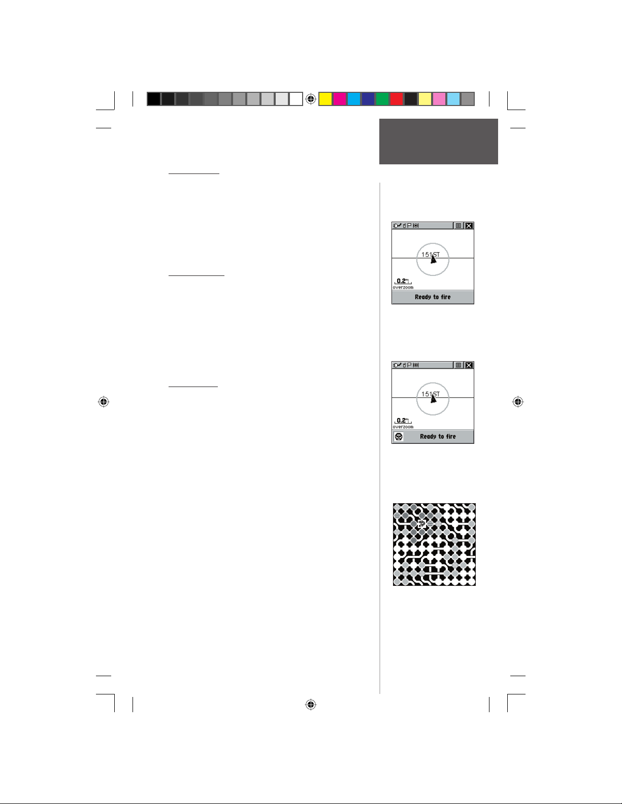
Main Menu Page
Clothesline
Team members select the same user symbol and then
attempt to “hit” or ‘clothesline” other players by pressing the TALK key when an opposing team member is
between them. You may also mark a point and assign it a
symbol to be used as a stationary team member. You must
wait 10 seconds between attempts. Press CALL to show
the score and PAGE to quit the game.
Assimilation
Think of this as a high-tech game of tag. Team
members select the same user symbol and then attempt
to assimilate others into their team by getting within 30
feet of them and pressing the TALK key. You can set a
time limit, with the largest team winning, or play until the
other team is completely assimilated! Set your own rules
and enjoy! Press CALL to show the score and PAGE to
quit the game.
Beast Hunt
The objective is to fi nd and kill the beast with an arrow before it incinerates you or you fall into one of several
pits while navigating a maze of platforms! From time to
time you will be transported by slides that curve or move
diagonally. When you think you know where the beast
is, from an adjacent spot, press Enter (IN on the CLICK
STICK) to initiate aiming. With the CLICK STICK,
point the arrow in the direction where you think the beast
is and press IN on the CLICK STICK to fi re. When you
lose a game, the screen will display the layout of hazards,
slides, warning platforms and the location of the beast.
A scoreboard keeps track of your wins and losses. Press
PAGE anytime during the game for further instructions, to
turn the sound On/Off or to quit.
Preliminary
Games
Clothesline
Assimilation
Beast Hunt
190-00284-00_Prelim_FCC.indd 63 9/18/2003, 3:51:34 PM
63
Page 74
Appendix A
FRS Explained
Preliminary
64
What is FRS?
FRS, or Family Radio Service, is a UHF radio
frequency band licensed by the FCC for general public
use. The operating frequency ranges from 462.5625 to
467.7125 MHz, with a transmitting power of one half
watt. FRS radios are small and lightweight, making them
ideally suited for outdoor activities.
The use of FRS radios does not require a license. FRS
was intended for use by families and small groups as an
inexpensive means of two-way voice communication.
The use of GMRS (General Mobile Radio Service)
radios do require a FCC license. The operating frequency
fro GMRS ranges from 462.550 to 462.725 MHz
FRS radios broadcast on one of 14 channels, each with
a specifi c frequency within the FRS band.
FRS is intended for use throughout the United States,
its territories and possessions. It may also be used in
Canada. FRS is not approved outside of these areas and
may interfere with local government communication
frequencies (fi re, police, etc.). GMRS use is currently not
allowed in Canada.
More sophisticated FRS radios also include call functions, squelch codes, channel scan, and voice scramble.
Call functions allow you to push a Call button on the
radio, and alert other radios set on the same channel.
This feature generates a call tone and is handy in a noisy
environment where the tone is easier to initially identify
than plain speech.
Squelch codes, are useful when a lot of radio traffi c
occurs on FRS frequencies. This allows you to selectively
block out other FRS users that are not part of your group.
They will still be talking with others in their own group,
but you will not hear them on your radio. They may or
may not hear you and members of your group on their
own radios. Squelch codes act as a fi lter, blocking your
FRS radio from hearing other unwanted FRS users.
Channel scan allows your FRS radio to scan all FRS
frequencies for signals. This is a great way to identify
an unused or less-used channel for your group. After
scanning briefl y to see what channels other users are on,
190-00284-00_Prelim_FCC.indd 64 9/18/2003, 3:51:34 PM
Page 75
simply set your FRS radios to an unused channel and
enjoy less interference. You may also fi nd this useful just
to listen in on others currently using FRS. After all, these
are public-use frequencies and everyone has a right to
talk or listen in.
For greater communication, some FRS radios have
a voice scramble feature. This features will cause your
message to sound garbled to other FRS users that are not
part of your group. However, it does not guarantee your
conversations will be 100 percent private and secure.
Other casual FRS users will not hear your messages, but
users with similar radios or more technically-oriented
users can still monitor your conversations.
FRS radios typically feature half watt transmit power.
You may encounter FRS radios with lower transmit power
specifi cations than this, but all are at least 100mW (0.1
watt). You can expect your FRS radio to offer reliable
operation at one-mile range. If the area between you and
another FRS operator is free of obstructions, operation up
to a two-mile range can be achieved.
What are the limitations?
If you are operating in an urban environment or in
varying terrain (canyons or mountains), these man-made
or natural features will act as obstructions limiting the
maximum reception range of your FRS radio. The UHF
FRS frequency is “line of sight”, meaning that the signals
do not follow the surface of the earth, but instead radiate
in a straight line from the transmitting antenna. If there
is an obstruction between the transmitting FRS radio and
the receiving FRS radio, the signal will not be received.
Smaller obstructions, such as trees, cars and even crowds
of people will cause some loss of signal, resulting in
reduced maximum range. Other FRS users can crowd
FRS frequencies. You may fi nd squelch codes and channel
scanning useful to minimize interference from other FRS
users.
Preliminary
Appendix A
FRS Explained
190-00284-00_Prelim_FCC.indd 65 9/18/2003, 3:51:35 PM
65
Page 76
Appendix B
Specifi cations
Physical
Case: Fully-gasketed, high-impact plastic alloy, waterproof to IPX7 standards
Size: 4.5”H x 2.3”W x 1.6”D; 7”H with antenna (11.4 x 5.8 x 4.1; 17.8 cm)
Weight: Approx. 7.6 ounces (236 g) w/batteries
Temperature Range: 5° to 158°F (-15° to 70°C) (operating)
Display: 1.4”H x 1.4”W (3.6 cm x 3.6 cm) 160 x 160 pixels, high-contrast LCD
Performance
Receiver: WAAS Enabled, Differential-ready, 12 parallel channel
Acquisition time: Approx. 15 seconds (warm start)
Update Rate: 1/second, continuous
GPS Accuracy: <15 meters (49 ft) RMS, 95% typical
DGPS (USGC) Accuracy: 3-5 meters (10-16 ft), 95% typical with DGPS corrections
DGPS (WAAS) Accuracy:
Velocity Accuracy: 0.05 meter/sec steady state
Dynamics: Performs to specifi cations to 6 g’s
Interfaces: NMEA 0183, RTCM 104 (for DGPS corrections) and
Antenna: Quad-helix
Radio
Channels: 22 (1-14 FRS, 15-22 GMRS) GMRS requires FCC license
Squelch Codes: 38
Range: Up to 2 miles on FRS; up to 5 miles on GMRS
Radio Output Power: FRS 0.5 watt; GMRS 1.0 watt
Power
Input: Three 1.5-volt AA batteries
Battery Life: GPS only - up to 28 hours; FRS only - up to 20 hours;
Specifi cations are subject to change without notice.
1
Subject to accuracy degradation to 100m 2DRMS under the U.S. DoD-imposed Selective Availability program.
2
With optional Garmin Differential Beacon Receiver Input (such as Garmin GBR 21 or 23).
3
The temperature rating for the Rino may exceed the usable range of some batteries. Alkaline batteries can rupture
at high temperatures. External power can only be applied using the Garmin Auto Power Adapter or PC Interface
Cable with Auto Power Adapter. These cables contain a 12 Vdc to 3 Vdc voltage regulator. Modifi cations or other
applications voids the product warranty.
4
Alkaline batteries lose a signifi cant amount of their capacity as temperature decreases. Use lithium batteries when
operating the Rino in below-freezing conditions. Extensive use of screen backlighting and the radio signifi cantly
reduces battery life. Different brands of batteries vary in performance.
5
5, 5, 90 Duty Cycle - 5% receive with audio unmuted, 5% transmit and 90% standby (receive with audio muted)
Preliminary
66
(waterproof to one meter for 30 minutes)
Approx. 45 seconds (EZinit/cold start)
Approx. 5 minutes (First Time/AutoLocate™)
1
<3 meters (10 ft), 95% typical with DGPS corrections
RS-232 for PC interface
3
FRS and GPS - up to 15 hours
5
2
2
190-00284-00_Prelim_FCC.indd 66 9/18/2003, 3:51:35 PM
Page 77
To obtain accessories, see your local dealer or visit the
Garmin web site at www.Garmin.com and click on Shop
link.
12-volt Adapter Cable: Provides unit power from an
automobile cigarette lighter.
2.5 to 3.5 mm Jack Adapter: Allows you to use 3rd
party headsets with your Rino unit..
Bash Guard Kit: Helps protect the Rino’s edges against
hard shocks. Includes 2 bash guards, quick-release neck
lanyard and belt clip.
Carrying Case: Protects the Rino and permits use while
in the case.
Earbud with PTT (Push To Talk) Mic: Earbud fi ts
snuggly inside of and has a clip-on mic with PTT button.
Flexible Ear Receiver: Comfortable earpiece for better
hearing ability of your Rino.
Headset with VOX Boom Mic: Hands-free at it’s best!
Utilize the Rino’s VOX (Voice Operated Transmission)
feature with this headset and voice activated boom mic.
Instructional Video: For getting accustomed to your
Rino basic operations quickly.
MapSource™ Map Data CD-ROMs: An excellent tool
for creating waypoints and routes on your PC using a
background map and downloading them to your Rino.
See your Garmin dealer for MapSource details.
NiMH Battery Charger: Why buy when you can
recharge? Includes NiMH battery charger and 4 AA NiMH
batteries.
PC Data Cable and 12-volt Adapter: Allows transfer of
waypoints and routes from a PC to the Rino and provides
unit power from an automobile cigarette lighter.
Rail/Handlebar Mount: Allows you to mount your Rino
on most rails or handlebars.
Suction Cup Mount: Allows you to mount your Rino on
most smooth surfaces or inside windscreens.
Preliminary
Appendix C
Accessories
190-00284-00_Prelim_FCC.indd 67 9/18/2003, 3:51:36 PM
67
Page 78
Appendix D
Transferring MapSource Map Data
MapSource
Setup
Garmin MapSource
CD-ROM’s offer a variety of
detailed mapping data and
navigation information.
MapSource is also an excellent
medium for storage and safety
backup of Personal Waypoints,
Routes and Saved Tracks.
See your Garmin Dealer or
visit the Garmin web site at:
www.Garmin.com
for
informa
tion.
Transferring Map Data:
You can transfer detailed map data to the Rino from a Garmin MapSource CD-ROM.
The Rino 130 can accept up to 8 MB of data from any MapSource program loaded on a
PC and connected to the Rino Data Port. For this function you need the PC Data Cable
provided with your unit.
Preliminary
If you have purchased a Garmin MapSource CD-ROM
mapping program you may want to transfer detailed map
data before beginning use, to provide your unit with
maximum Find features and mapping capability. The Rino
accepts up to 8 MB of map data from most MapSource
products. It is not possible to transfer 3rd party maps into
Garmin products.
You cannot view multiple types of MapSource data in
the same location at the same time (one will draw over the
other). When you leave a MetroGuide area for example
and enter the area of a topographic map, the display will
change to contour lines. The same is true when moving
from a topo map to a MetroGuide map.
The BlueChart maps are at the top of the hierarchy and
will replace any other map information. Here is the list of
the hierarchy for your reference beginning with those titles
that take precedence:
1. BlueChart 2. MetroGuide 3. Fishing Hot Spots
4. Points of Interest 5. U. S. Waterways & Lights
6. U. S. Topo 7. Roads and Recreation 8. WorldMap
Map data transfer requires the use of a PC, a Garmin
MapSource CD-ROM, and the PC Interface Cable with RS232 serial port connector supplied with this unit. Follow
detailed instructions for data transfer in the MapSource
User’s Manual.
To setup for data transfer:
1. Remove the Power/Data Port cover on the back of the unit by lifting up on the
protective cover on the back of the unit.
2. Connect the serial port connection on the cable to the PC serial port.
3. Connect the remaining cable connector to the back of the Rino by orienting the slot
on the connector with indexing bar on the back of the unit. Then, slide the connector
in place. Be sure that the cable is pushed all the way into the back of the unit!
4. Turn on the Rino and follow instructions for map data transfer provided in the
MapSource User’s Manual. See also page 55 for unit interface settings.
68
190-00284-00_Prelim_FCC.indd 68 9/18/2003, 3:51:36 PM
Page 79

Appendix E
To resolve problems that cannot be remedied using
this guide, contact Garmin Customer Service at:
913-397-8200 or 800-800-1020
Symptom Probable Cause Remedy
GPS Troubleshooting
Guide
Unit does not turn on.
Unit does not turn ON,
even with new batteries.
The unit turns On, then turns
It takes more than ten minutes
Cannot access a WAAS system
satellite after 2 to 5 minutes.
Cannot obtain a differential
Cannot access Point of Interest,
Street, or Intersection Find
Cannot view a track being laid
down on the map page when
Cannot see the panning arrow
Off.
to get a location fi x.
position from WAAS.
Lists.
Preliminary
traveling.
on the Map Page easily.
Batteries are exhausted.
Batteries may be installed backwards.
You are pressing and releasing
POWER button.
Batteries may be nearly exhausted.
The unit’s view of satellites is
obstructed.
Your view of the satellite is obstructed
or you are located too far from satellites
currently in service for the Americas.
System GPS operation is set to something other ‘Normal’ and/or interface
setting is for RTCM.
You have not collected enough infor-
mation from the WAAS satellite.
MetroGuide map data is not activated.
The Track Log feature is turned Off.
There is too much map clutter or the
scale is such that map features are too
densely displayed.
the
Move to a location with a clear view
Move to a location with a clear view
Wait 10-20 minutes for the initial col-
lection, then 1-2 minutes afterwards.
Access the Map Setup ‘Map’ option
the ‘ON’ button and press in on the
Replace batteries.
Reinstall batteries.
You must press and hold the
POWER button for two seconds.
Replace batteries.
of the sky.
and point the unit antenna in the
direction of the satellite.
Set system GPS to ‘Normal’ and
interface to other than RTCM.
and activate the check box.
Access the Tracks Page, highlight
CLICK STICK.
Use the Map Page Setup Page to
reduce map clutter or change the
map scale.
Cannot exit a menu or page
by moving the CLICK STICK to
The Rino is programmed to provide “pop-up” messages concerning operational characteristics and conditions.
Press in on the
190-00284-00_Prelim_FCC.indd 69 9/18/2003, 3:51:37 PM
the left.
CLICK STICK
Some menus and pages have an ‘X’
(Exit) on-screen button in the upper
right corner.
to acknowledge a message and return to the current feature.
Highlight the on-screen button and
then press in on the CLICK
STICK.
69
Page 80
Appendix E
To resolve problems that cannot be remedied using this
Radio Troubleshooting
Guide
Symptom Probable Cause Remedy
guide, contact Garmin Customer Service at:
913-397-8200 or 800-800-1020
Radio not transmitting.
Messages not being received
by others
Limited talk range
You can hear others, but they
can’t hear you or you see an
incoming transmission, but
nothing is heard.
Message garbled.
Too many unwanted conversa-
tions being heard.
Interference or static
Cannot transmit location.
Preliminary
None of the keys except TALK
will work.
TALK key may not be fully depressed.
Radio feature not set to On.
Incorrect channel/code setting. Out of
radio range or obstructions.
Natural or man-made obstructions can
decrease range.
You’re on the same channel, but
different code set.
Scramble option is enabled (130 Only)
Too many user on channel or code is
set to zero.
Radios too far apart or too close
Obstructions in radio line of sight..
Interference from other electronics.
Your view of the satellite is obstructed
and a GPS fi x is not available, ‘Send
Location’ is off ; 10 seconds have not
elapsed since last location transmission,
or GPS is set to Off.
Keylock is enabled
Press and hold TALK key in until
done talking. Turn radio On.
Make sure other radios have
the same channel and code set.
Decrease distance between radios.
Decrease distance between radios or
obtain a better line of sight between
If you are using code zero, you will
hear all transmissions on that chan-
nel. Use the same code (1-38) as
the other party or use ‘Scan’ to fi nd
Both radios need to have this
Switch to a different channel and/or
use code other than zero (1-38).
Keep radios at least 3 feet apart.
Obtain better line of sight between
radios. Shut off other devices or
move away from interfering area.
Move to a location with a clear view
of the sky. Enable ‘Send Location’.
Wait 10 seconds between location
Hold PAGE for 5 seconds to release
radios.
what code they are on.
feature set the same.
transmission. Enable GPS.
keylock..
The Rino is programmed to provide “pop-up” messages concerning operational characteristics and conditions.
Press in on the
CLICK STICK
to acknowledge a message and return to the current feature.
70
190-00284-00_Prelim_FCC.indd 70 9/18/2003, 3:51:38 PM
Page 81
The following data fi eld options are available on the
Map, Navigation and Trip Computer Main Pages.
Bearing - The direction from your current location to a
destination.
Course - The direction from your starting location to a
destination.
Current Destination - The next waypoint on your
route.
Current Distance - The remaining distance to your
next waypoint.
Current ETA - The estimated time of day you will
arrive at your next waypoint.
Current ETE - The estimated time needed to arrive at
the next waypoint on your route.
Elevation - The altitude (height) above or below sea
level.
Final Destination - The last waypoint on your route.
Final Distance - The remaining distance to your fi nal
destination.
Final ETA - The estimated time of day you will reach
your fi nal destination.
Final ETE - The estimated time needed to reach your
fi nal destination.
GPS Accuracy - The estimated accuracy of the GPS
signal.
Heading - Your moving direction.
Location (lat/lon) - Your current GPS position.
Location (selected) - The lat/lon of point defi ned on
Maximum Speed - The maximum speed the unit has
Moving Avg. Speed - Average speed of the unit
Odometer - A running tally of distance travelled,
Off Course - The distance left or right you are from
Overall Avg. Speed - Your average speed.
Preliminary
map.
moved.
while moving.
based upon the distance between second-by-second
position readings.
the original course (path of travel).
Appendix F
Data Field
Defi nitions
71
190-00284-00_Prelim_FCC.indd 71 9/18/2003, 3:51:38 PM
Page 82
Appendix F
Data Field
Defi nitions
Pointer - Indicates the direction to the next
destination.
Speed - Your rate of travel can be displayed in
miles per hour, kilometers per hour, or nautical miles
per hour.
Sunrise - The time at which the sun rises on this
day.
Sunset - The time at which the sun sets on this day.
Time of Day - The time for the selected time zone.
To Course - The compass direction you must go in
order to get back to the original course.
Trip Odometer - A running tally of distance
travelled since last reset.
Trip Time - Moving - A running tally of movement
time travelled since last reset.
Trip Time - Stopped - A running tally of stopped
time travelled since last reset.
Trip Time - Total - A running tally of all travel time
since last reset.
Turn - The angle difference (in degrees) between
the bearing to your destination and your current line
of travel. ‘L’ means turn Left. ‘R’ means turn Right.
Velocity Made Good - The speed at which you
are closing on a destination along a desired course.
Vertical Speed - Your rate of altitude gain/loss
over time.
Preliminary
72
190-00284-00_Prelim_FCC.indd 72 9/18/2003, 3:51:39 PM
Page 83
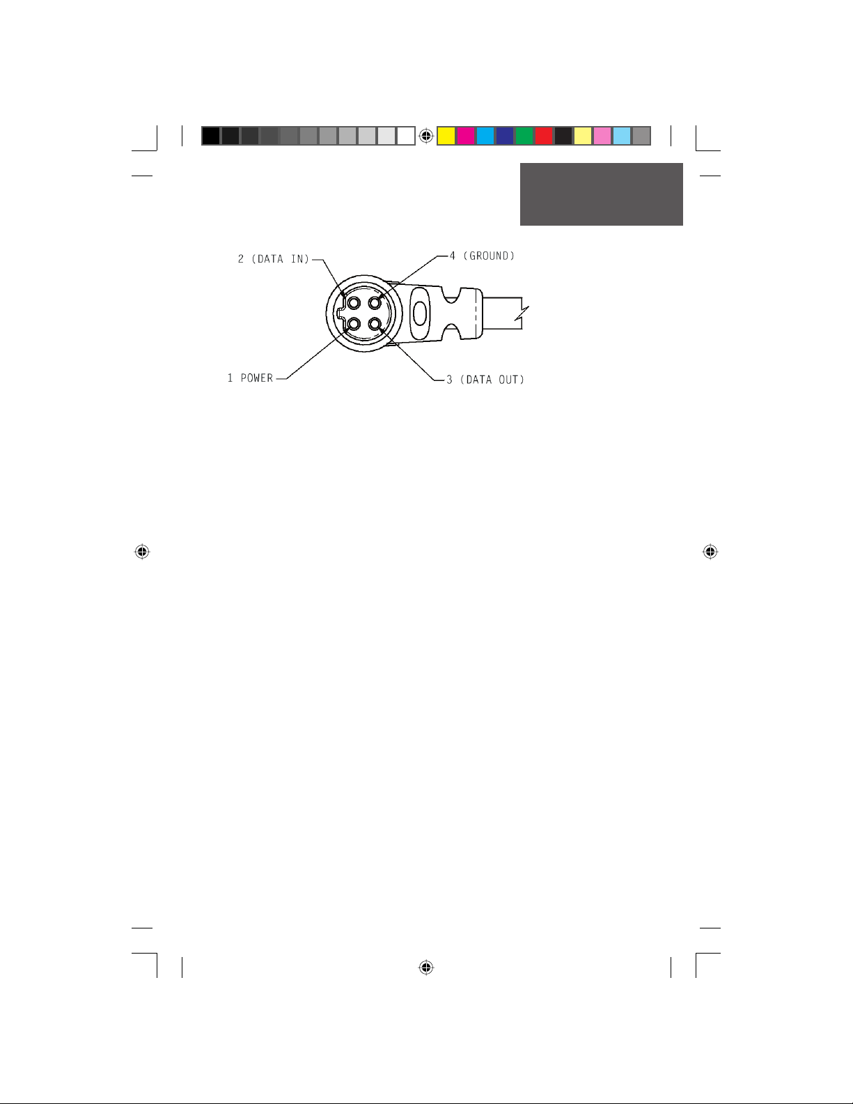
Appendix G
Wiring Diagram
Cable View
Interface formats are selected from the Setup ‘Interface Page’ on page 55 of this
manual. See also page 68 for using the Rino with MapSource. The input/output lines
on your Rino unit are RS-232 compatible, allowing easy interface to a wide range of
external devices, including PC’s, differential beacon receivers, marine autopilots and /or
a second GPS receiver.
The NMEA 0183 version 3.0 interface format is supported by the Rino and enables
the unit to drive up to three NMEA devices.
NMEA 0183 Version 3.0 Approved Sentences:
GPGGA, GPGLL, GPGSA, GPGSV, GPRMB, GPRMC, GPRTE, GPVTG, GPWPL,
GPBOD
Garmin Proprietary Sentences:
PGRME (estimated error), PGRMM (datum string), PGRMZ (altitude), PSLIB (beacon
receiver control)
DGPS (Differential GPS) corrections are accepted in RTCM SC-104 version 2.0 format through the ‘Data In’ line. The Garmin GBR 21 and GBR 23 are the recommended
beacon receivers for use with the Rino. Other beacon receivers with the correct RTCM
format may be used, but may not correctly display status or allow tuning control from
the GPS unit.
The Rino may be hard-wired to a serial connector using a Data Only Cable. Refer to
the wiring diagram and the Rino unit data connection illustrated below.
The PC Interface Cable provided with this unit allows you to connect your Rino to a
PC-compatible computer’s serial port.
190-00284-00_Prelim_FCC.indd 73 9/18/2003, 3:51:39 PM
Preliminary
73
Page 84
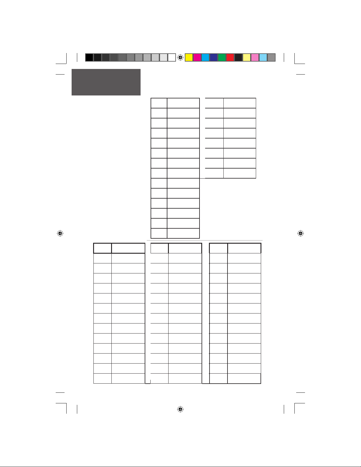
Appendix H
Frequency Chart
NOTE: If you plan to
purchase FRS radios from
third party manufacturers
be aware that there are
CTCSS differences in some
radios. Some of the tones
on one radio may not be
available on other radios.
Charts showing the different codes and manufacturers can be located on the
World Wide Web.
FRS
Channel
Frequency
1 462.5625 15 462.550
2 462.5875 16 462.575
3 462.6125 17 462.600
4 462.6375 18 462.625
5 462.6625 19 462.650
6 462.6875 20 462.675
7 462.7125 21 462.700
8 467.5625 22 462.725
9 467.5875
10 467.6125
11 467.6375
12 467.6625
13 467.6875
14 467.7125
GMRS
Channel
Frequency
Code
74
190-00284-00_Prelim_FCC.indd 74 9/18/2003, 3:51:41 PM
Frequency
1 67 14 107.2 27 167.9
2 71.9 15 110.9 28 173.8
3 74.4 16 114.8 29 179.9
4 77 17 118.8 30 186.2
5 79.7 18 123 31 192.8
Preliminary
6 82.5 19 127.3 32 203.5
7 85.4 20 131.8 33 210.7
8 88.5 21 136.5 34 218.1
9 91.5 22 141.3 35 225.7
10 94.8 23 146.2 36 233.6
11 97.4 24 151.4 37 241.8
12 100 25 156.7 38 250.3
13 103.5 26 162.2
Code
Frequency
Code
Frequency
Page 85
A
Accessories.... .............................................. 67
Accuracy Circle ...........................................15
Activate a Route .......................................... 43
Alarm Clock .....................................26-27, 58
Area Calculation Page....................... 26-27, 61
Arrow, Panning............................................ 17
AutoZoom................................................... 19
B
Backlight Timer........................................... 56
Backlighting On/Off ....................................56
Battery Level Indicator .................................. 3
Battery Saver Mode...................................... 56
Battery Type........................................... 56, 66
Beacon Receiver Setup................................. 55
Bearing Pointer................................. 21-22, 43
Big Compass................................................ 22
Big Numbers ...............................................25
C
Calculator Page ................................26-27, 58
Calendar Page ..................................26-27, 57
Call Button.......................................11, 62-63
Call Tone....................................................... 7
Cancel Goto .......................................... 16, 23
Cautions.................................................... iii-v
Change Course Pointer Scale....................... 22
Channels .................................... 2, 4, 6, 64-66
Cities, By Name........................................... 33
Cities, Nearest ............................................. 33
Codes, Squelch........................... 2, 4, 6, 64-66
Compass Ring ............................................. 21
Contact Bar ........................................... 12, 14
Contact, Deleting ........................................ 30
Contact Details............................................ 12
Contact List........................................... 12, 32
Contact, New .........................................11-12
Contact, Proximity ......................................47
Contrast ......................................................56
Course Pointer ............................................ 22
Preliminary
D
Data Fields ................................18, 22, 25, 44
Data Field Defi nitions............................. 71-72
Date and Time Setup................................... 51
Detail, Map.................................................. 19
Differential GPS (DGPS) .........................55-56
Display Mode .............................................. 19
Index
E
Elevation .............................................. 18, 48
Exit Services ...........................................33-34
Exits.......................................................33-34
Exits, Nearest .........................................33-34
F
Fields, Data ...............................18, 22, 25, 44
Find Address..........................................35-36
Find Cities................................................... 33
Find Contacts.............................................. 32
Find Exits............................................... 33-34
Find Intersections...................................35-36
Find Last Found Place................................. 37
Find ‘N Go Menu ........................26-27, 31-37
Find Points of Interest ............................ 34-35
Find Waypoints........................................... 32
Frequency Chart.......................................... 74
G
Games Page .................................26-27, 62-63
Global Positioning System (GPS)............ iii, 48
GMRS License ...........................................ii-iii
GMRS Radio.................................... 2, 4, 8, 64
Goto............................................................ 38
Goto Line .................................................... 19
H
Heading Selection........................................ 54
Headset Type .............................................. 7-8
Hunt and Fish Page ..........................26-27, 60
I
Informational Picture............................2, 9-10
Initialization ................................................ 48
Interface Page .............................................. 55
K
Keylock ......................................................... 2
L
Location (Marking).................................28-29
Loading Map Data ................................. 55, 68
Lock On Road ............................................. 19
M
Main Menu Page..................................... 26-27
75
190-00284-00_Prelim_FCC.indd 75 9/18/2003, 3:51:42 PM
Page 86
Index
Map Datums........................................... 52-53
Map Display ................................................ 14
Map Features......................................... 15, 19
Map Page................................................14-20
Map Page Options ....................................... 16
Map Page Panning..................................16-17
Map Page Setup................................. 16,19-20
Map Scale.................................................... 15
MapSource Map Data ...................... 19, 55, 68
Mark a Waypoint................................... 28, 29
Mark Waypoint Page..............................26-28
Measuring Between Waypoints.................... 20
Monitor .....................................................5-6
Moving a Route Waypoint......................42-43
My ID................................................... 3-4, 11
N
Navigation Page...................................... 21-23
Nearest (Waypoints, Cities, Exits, etc.) ...31-36
New Contact Page .................................. 11-12
NMEA ................................................... 55, 66
Normal Mode.............................................. 56
North Reference ..........................................54
North Up .............................................. 19, 50
O
Odometer............................................... 24-25
Offset (Time)............................................... 51
Orient Map.................................................. 19
Overall Average Speed................ 18, 24-25, 72
Routes .................................................... 39-44
Creating.................................................. 39
Copying.................................................. 40
Deleting .................................................. 40
Naming................................................... 40
Editing...............................................40-42
Inverting ................................................. 40
Navigating .........................................43-44
Route Map Page ................................. 42-43
S
Satellite Page ...............................26-27, 48-50
Saving the Tracklog ................................45-46
Scan ...........................................................5-6
Scanlist.......................................................... 6
Scramble (Voice) ..................................... 8, 13
Selecting a Page ........................................... 26
Send Location ................................... 8, 11, 13
Serial Number ............................................ vii
Setup Page...................................26-27, 51-56
Show Contact Bar........................................ 16
Show Data Fields Bar................................... 16
Show Map Only .......................................... 16
Software Version (Operating)....................... 56
Specifi cations .............................................. 66
Stop Navigation..................................... 16, 23
Stopwatch Page ................................26-27, 59
Sun and Moon Page..........................26-27, 60
Symbol, User .......................... 3, 4, 11, 13, 63
Symbol, Waypoint ................................ 28, 30
Symbols, Status Bar ...................................... 3
System Setup............................................... 56
P
Page Sequence Setup ................................... 26
Panning (Map) .................................16-17, 28
Peer-to-peer....................................... 8, 11, 13
Position Format...................................... 52-53
Projecting a Point ........................................ 30
Proximity Page .................................26-27, 47
Preliminary
R
Radio Page................................................2-13
Radio Page Setup........................................ 7-8
Reset Trip Page ....................................... 24-25
Ring Tone ...................................................... 7
Roger Tone .................................................... 7
76
190-00284-00_Prelim_FCC.indd 76 9/18/2003, 3:51:43 PM
T
Talk Button....................................... 11, 62-63
Text Size................................................ 16, 19
Time Format ............................................... 51
Time Zone................................................... 51
TracBack................................................. 45-46
Track Logs........................................19, 45-46
Track Log Saving ......................................... 46
Track Log Setup........................................... 46
Tracks Page..................................26-27, 45-46
Track Up ............................................... 19, 50
Trip Computer Page ...............................24-25
Trip Odometer....................................... 24-25
Trip Time ...............................................24-25
Troubleshooting .....................................69-70
Page 87
Turning the GPS Receiver “Off” .....................7
Turning the Radio “Off”................................. 7
U
Unit Features........................................... 1, 66
Units of Measure ....................................52-53
Units Page .............................................. 52-53
User Symbol............................ 3, 4, 11, 13, 63
UTC Offset.................................................. 51
V
Vibrate .......................................................... 7
View Waypoints on Route ............................. 9
VOX Level..................................................... 8
W
WAAS, Enable/Disable................................. 56
Warnings................................................... iii-v
Waypoints.......................................................
Deleting .................................................. 30
Editing.................................................... 30
List ......................................................... 32
Marking .................................................. 29
Naming................................................... 29
Projecting ............................................... 30
Proximity................................................ 47
Sending ........................................ 8, 11, 13
Symbols ............................................ 28, 30
What is FRS ...........................................64-65
Wiring Diagram (Interface).......................... 73
Index
Z
Zooming In/Out ......................................... 15
Zoom Ranges............................................... 15
190-00284-00_Prelim_FCC.indd 77 9/18/2003, 3:51:44 PM
Preliminary
77
Page 88
For the latest free software updates throughout the
life of your Garmin products, visit the Garmin web site
at www.Garmin.com
Preliminary
© 2003 Garmin Ltd. or its subsidiaries
Garmin International, Inc.
1200 East 151st Street, Olathe, Kansas 66062, U.S.A.
Garmin (Europe) Ltd.
Unit 5, The Quadrangle, Abbey Park Industrial Estate, Romsey, SO51 9DL, U.K.
Garmin Corporation
No. 68, Jangshu 2nd Road, Shijr, Taipei County, Taiwan
www.garmin.com
Part Number 190-00284-00 Rev. A
190-00284-00_Prelim_FCC.indd 78 9/18/2003, 3:51:44 PM
 Loading...