

Garland XPE12-0L, XPE12-0R, XPG12-0L, XPG12-0R, XPE24-1L Service Manual
...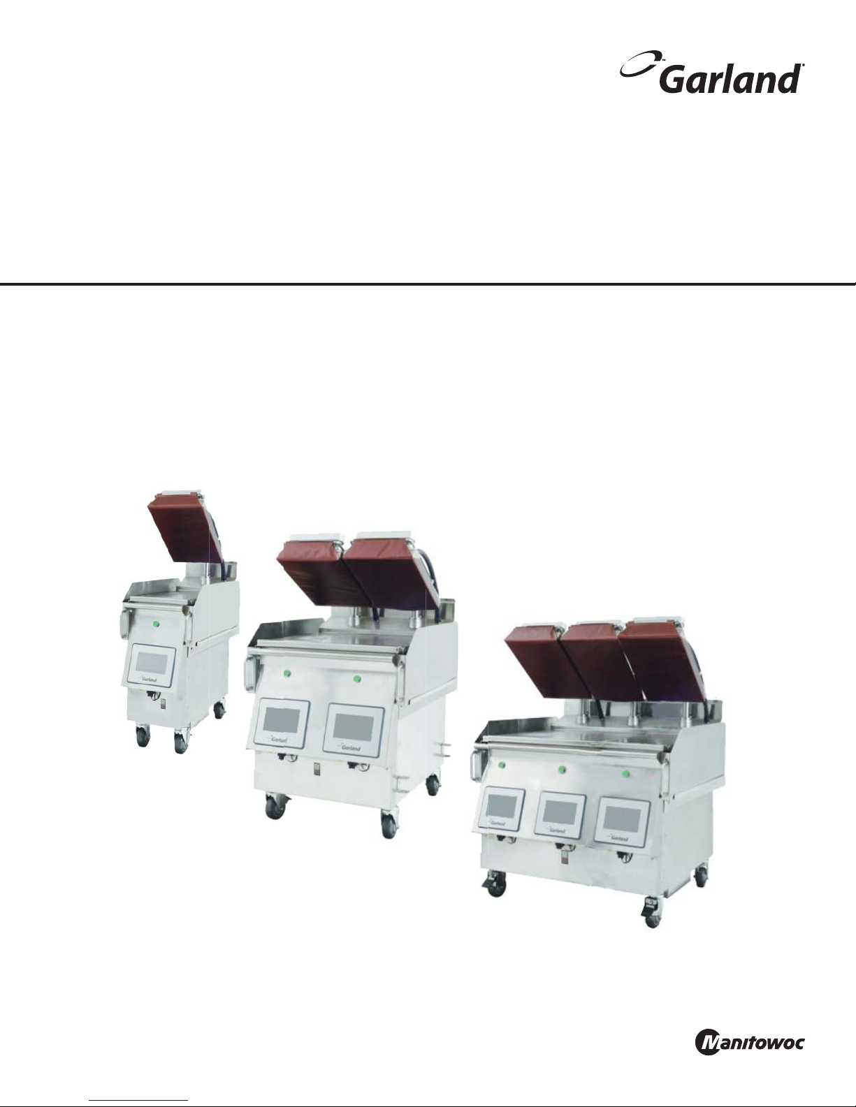
Electric/Gas Dual Side Xpress Plus Grill
Models:
XP(E/G)12
XP(E/G)24, XP(E/G)24-1(L/R)
XP(E/G)36, XP(E/G)36-1(L/R), XP(E/G)36-2(L/R)
Service Manual
Please read all sections of this manual and retain for future reference.
For your safety:
Post in a prominent location, instructions to be followed
in the event the user smell gas. This information shall be
obtained by consulting your local gas supplier.
DRAFT VERSION
XP(E/G)12 Shown
XP(E/G)24 Shown
Original Instructions
Document: GAR_SM_4601777 (4/16)
XP(E/G)36 Shown

THIS PAGE INTENTIONALLY LEFT BLANK
Safety Notices
DEFINITIONS
DANGER
Indicates a hazardous situation that, if not avoided, will
result in death or serious injury. This applies to the most
extreme situations.
Warning
Indicates a hazardous situation that, if not avoided,
could result in death or serious injury.
Caution
Indicates a hazardous situation that, if not avoided,
could result in minor or moderate injury.
Notice
Indicates information considered important, but not
hazard-related (e.g. messages relating to property
damage).
NOTE: Indicates useful, extra information about the
procedure you are performing.
DISCLAIMERS
DANGER
It is the responsibility of the equipment owner to
perform a Personal Protective Equipment Hazard
Assessment to ensure adequate protection during
maintenance procedures.
DANGER
The on-site supervisor is responsible for ensuring that
operators are made aware of the inherent dangers of
operating this equipment.
NOTE: Proper installation, care and maintenance are
essential for maximum performance and trouble-free
operation of your equipment. Visit our website
www.mtwkitchencare.com for manual updates,
translations, or contact information for service agents in
your area.
Warning
Do Not Store Or Use Gasoline Or Other Flammable
Vapors Or Liquids In The Vicinity Of This Or Any Other
Appliance. Never use flammable oil soaked cloths or
combustible cleaning solutions, for cleaning.
Warning
Do not store combustible materials on the appliance.
Warning
Only trained and authorized service personnel or store
manager should access the service screens. If changes
to these settings are made incorrectly they will cause
the unit to malfunction.
Caution
Maintenance and servicing work other than cleaning as
described in this manual must be done by an authorized
service personnel.
DANGER
Do not install or operate equipment that has been
misused, abused, neglected, damaged, or altered/
modified from that of original manufactured
specifications.
DANGER
All utility connections and fixtures must be maintained
in accordance with local and national codes.
Warning
Warning labels mounted directly on the equipment
must be observed at all times and kept in a fully legible
condition.
Warning
Read this manual thoroughly before operating, installing
or performing maintenance on the equipment. Failure
to follow instructions in this manual can cause property
damage, injury or death.
Warning
This appliance is not intended for use by persons
(including children) with reduced physical, sensory or
mental capabilities, or lack of experience and knowledge,
unless they have been given supervision concerning
use of the appliance by a person responsible for their
safety. Do not allow children to play with this appliance.
Notice
Routine adjustments and maintenance procedures
outlined in this manual are not covered by the warranty.
Warning
This product contains chemicals known to the State
of California to cause cancer and/or birth defects or
other reproductive harm. Operation, installation, and
servicing of this product could expose you to airborne
particles of glass-wool or ceramic fibers, crystalline
silica, and/or carbon monoxide. Inhalation of airborne
particles of glass-wool or ceramic fibers is known to the
State of California to cause cancer. Inhalation of carbon
monoxide is known to the State of California to cause
birth defects or other reproductive harm.
ELECTRICAL
DANGER
Check all wiring connections, including factory
terminals, before operation. Connections can become
loose during shipment and installation.
DANGER
Do not operate any appliance with a damaged/pinched
cord or plug. All repairs must be performed by a qualified
service company.
LOCATION
Warning
Two or more people or a lifting device are required to lift
this appliance.
Warning
To avoid instability the installation area must be capable
of supporting the combined weight of the equipment
and product. Additionally the equipment must be level
side to side and front to back.
Warning
No structural material on the appliance should be
altered or removed to accommodate placement of the
appliance under a hood.
Warning
Be aware of the red mark in the threaded steem caster
to indicated the maximum adjustment. Adjusting above
the red mark could cause the caster to fail & the unit to
tip. For more information see installation section 2.
Warning
The appliance must be isolated from the gas supply
piping system by closing its individual manual
shutoff valve during any pressure testing of the gas
supply piping system at test pressures equal to or
less than ½ psi (3.5 kPa).
Caution
This equipment must only be operated under an
approved hood system in accordance with local regulations
in force. This unit is intended for indoor use only.
DANGER
Failure to disconnect the power at the main power
supply could result in serious injury or death. The power
switch DOES NOT disconnect all incoming power.
DANGER
Copper wire suitable for at least 75°C (167°F) must be
used for power connections.
Warning
This appliance must be grounded and all field wiring
must conform to all applicable local and national
codes. Refer to rating plate for proper voltage. It is the
responsibility of the end user to provide the disconnect
means to satisfy the authority having jurisdiction.
Warning
Do not use electrical appliances or accessories other
than those supplied by the manufacturer.
Warning
This equipment must be positioned so that the plug is
accessible unless other means for disconnection from
the power supply (e.g., circuit breaker or disconnect
switch) is provided.
Warning
Disconnect electric power at the main power disconnect
for all equipment being serviced. Observe correct
polarity of incoming line voltage. Incorrect polarity can
lead to erratic operation.
Warning
Never touch anything that runs on electricity when your
hands are wet.

CODE
CLEARANCE
Warning
Authorized Service Representatives are obligated to
follow industry standard safety procedures, including,
but not limited to, local/national regulations for
disconnection / lock out / tag out procedures for all
utilities including electric, gas, water and steam.
Warning
For an appliance equipped with casters, (1) the installation
shall be made with a connector that complies with the
Standard for Connectors for Movable Gas Appliances ANSI
Z21.69 • CSA 6.16, and a quick-disconnect device that
complies with the Standard for Quick-Disconnect Devices
for Use With Gas Fuel, ANSI Z21.41 • CSA 6.9, (2) adequate
means must be provided to limit the movement of the
appliance without depending on the connector and the
quick-disconnect device or its associated piping to limit
the appliance movement and (3) the location(s) where
the restraining means may be attached to the appliance
shall be specified.
DAMAGE
DANGER
Improper installation, adjustment, alteration, service,
or maintenance of this appliance or installation of
a damaged appliance can result in DEATH, INJURY,
EQUIPMENT DAMAGE, and void the warranty. NEVER
install damaged appliances, equipment, or accessories.
ALWAYS have installation and service performed by
trained and authorized personnel.
Caution
Pouring water or ice on a hot heating elements/heated
surfaces will cause damage..
Warning
Pinch Hazard. Keep hands and tools clear from the area
above the platens when platens are in motion towards
the exhaust hood. Be aware that adjacent platens may
unexpectedly move at any time. “Turn Grill Off” at
main switch when cleaning platens as there can be an
unexpected movement of the platens
Caution
Do not block the supply and return air vents or the air
space around the air vents. Keep plastic wrappings,
paper, labels, etc. from being airborne and lodging in
the vents. Failure to keep the air vents clear will result in
unsatisfactory operation of the system.
Caution
Do not position the air intake vent near steam or heat
exhaust of another appliance.
Warning
Slipping Hazard: Grease from food products will splatter.
The areas surrounding the grill are a slipping hazard due
to the splatter zone. Clean the area surrounding the grill
regularly. The grill may be slippery. Ensure floor area is
clean. Care needs to be taken as equipment may be hot.
Warning
Failure to maintain required clearances and additional
distances as needed can result in INJURY and
EQUIPMENT DAMAGE.
Consult manufacturers’ literature, and sales and service
agencies as needed.
DANGER
To reduce the risk of fire, the equipment is to be
installed in non-combustible surroundings only, with no
combustible material within 18” (457 mm) of the sides,
front or rear of the appliance or within 40 “ (1 m) above
the appliance. The appliance is to be mounted on floors
of noncombustible construction with noncombustible
flooring and surface finish and with no combustible
material against the underside or on noncombustible
slabs or arches and have no combustible material
against the underside. Such construction shall in all
cases extend not less than 12” (305 mm) beyond the
equipment on all sides.
DANGER
Risk of fire/shock. All minimum clearances must be
maintained. Do not obstruct vents or openings.
Warning
Pinch Hazard. Ensure a minimum of 1" clearance
between the hood and the uppermost position of the
platen arm. To reduce the risk of chrushing injuries
between platen & hood.
CLEANING
Caution
Ensure platens are down, in closed position, when
moving grill. Follow the procedure to avoid potential
damage, loss of calibration on the platen, and error
messages.
Caution
Never use an acid based cleaning solution on exterior
panels! Many food products have an acidic content,
which can deteriorate the finish. Be sure to clean the
stainless steel surfaces of ALL food products.
Caution
Do not use caustic cleaners on any part of the equipment
or equipment cavity . Use mild, non abrasive soaps or
detergents, applied with a sponge or soft cloth. Never
use sharp implements or harsh abrasives on any part of
the equipment.
Warning
When cleaning interior and exterior of unit, care should
be taken to avoid front power switch and the power
cord(s). Keep water and/or cleaning solutions away from
these parts.
Warning
Turn grill off and unplug the unit before cleaning the
side/back panels. Do not remove any panel during
cleaning.
Warning
Interior cleaning must be performed by a qualified
service technician only.
Warning
Never use a high-pressure water jet for cleaning or hose
down or flood interior or exterior of units with water. Do
not use power cleaning equipment, steel wool, scrapers
or wire brushes on stainless steel or painted surfaces.
Warning
Be aware that adjacent platens may unexpectedly move
at any time. “Turn Grill Off” at main switch when cleaning
platens as there can be an unexpected movement of the
platens.
PERSONAL PROTECTION
DANGER
All utilities (gas, electric, water and steam) must be OFF
to all equipment and locked out of operation according
to OSHA approved practices during servicing. Always
allow unit to cool.
DANGER
Use appropriate safety equipment during installation
and servicing.
DANGER
Never stand on the unit! They are not designed to
hold the weight of an adult, and may collapse or tip if
misused in this manner.
DANGER
Keep power cord AWAY from HEATED surfaces. DO NOT
immerse power cord or plug in water. DO NOT let power
cord hang over edge of table or counter.
Warning
DO NOT use the unit for storage. DO NOT leave paper
products, cooking utensils, or food in the unit when not
in use.
Warning
Allow heated equipment to cool down before
attempting to clean, service or move. Unit must be cool
to touch and disconnected from power source.
Warning
Always wear some type of protective covering on your
hands and arms when opening the unit.
Caution
Use a commercial-grade cleaner formulated to
effectively clean and sanitize food contact surfaces. Read
the directions for use and precautionary statements
before use. Particular attention must be paid to the
concentration of cleaner and the length of time the
cleaner remains on the food-contact surfaces.
Warning
Steam can cause serious burns. Always wear some type
of protective covering on your hands and arms when
opening the unit. When platen is Lifting, move away
face and body from the escaping steam.
Warning
Remove all removable panels before lifting and
installing.
Warning
Do not contact moving parts.
Warning
When using cleaning fluids or chemicals, rubber gloves
and eye protection (and/or face shield) must be worn.
Warning
Use caution when handling all metal surface edges of
the equipment.
Warning
This equipment is intended for indoor use only. Do not
install or operate this equipment in outdoor areas.
Warning
All covers and access panels must be in place and
properly secured, before operating this equipment.
Warning
Do not spray aerosols in the vicinity of this appliance
while it is in operation.
Warning
Risk of burns from high temperatures. You may get
burnt if you touch any of the parts during cooking.
Surfaces close to the cooking surface including side
panels may get hot enough to burn skin. Use extreme
caution to avoid coming in contact with hot surfaces
or hot grease. Wear personal protective equipment.
Warning
This appliance must be installed with sufficient
ventilation to prevent the occurrence of unacceptable
concentrations of substances harmful to the health of
personnel in the room in which it is installed.
Warning
Hazard. Keep hands and tools clear from the area above
the platens when platens are in motion towards the
exhaust hood. Be aware that adjacent platens may
unexpectedly move at any time. “Turn Grill Off” at
main switch when cleaning platens as there can be an
unexpected movement of the platens.
Warning
Slipping Hazard: Grease cans must be properly installed
before use. Improper installation will result in grease
on the floor which will create a slipping hazard. Ensure
grease cans are emptied and cleaned as needed to
prevent grease from overflowing onto the floor. The grill
may be slippery. Ensure floor area is clean. Care needs to
be taken as equipment may be hot
Warning
Pinch Hazard. Keep hands and tools clear of area between
platen and grill plate when platens are in motion. Be
aware that adjacent platens may unexpectedly move at
any time. “Turn Grill Off” at main switch when cleaning
platens as there can be an unexpected movement of the
platens.
Warning
Post in a prominent location, instructions to be followed
in the event the user smell gas. This information shall be
obtained by consulting your local gas supplier.
Warning
When checking for burner ignition or performance, do
not get too close to the burners. Slow ignition can cause
possible flashback, increasing the potential for facial
and body burns.

Safety Notices
Section 1
General Information
Section 2
Installation
Table of Contents
Definitions.................................................................................................................................................3
Disclaimers ................................................................................................................................................3
Location .....................................................................................................................................................4
Electrical ....................................................................................................................................................4
Damage......................................................................................................................................................5
Clearance ...................................................................................................................................................5
Read This Manual ............................................................................................................. 11
Unit Inspection .................................................................................................................11
Model Numbers ................................................................................................................11
Serial Plate Numbers ........................................................................................................11
Main Features and Components .....................................................................................12
Items included with the purchase of your new grill from manufacturer: ....................13
3 Platen Dimensions Specification .................................................................................14
2 Platen Dimensions Specification .................................................................................15
1 Platen Dimensions Specification .................................................................................16
Electrical Input Specification - WYE (electric XPE-12 CE models) ................................. 17
Electrical Input Specification - DELTA (electric XPE-12 models) ...................................17
Electrical Input Specification - WYE (gas XPG-12-CE models) ......................................17
Electrical Input Specification - DELTA (gas XPG-12 models) .........................................17
Electrical Input Specification - WYE (electric XPE-24 CE models) ................................. 18
Electrical Input Specification - DELTA (electric XPE-24 models) ...................................18
Electrical Input Specification - WYE (gas XPG-24 CE models) ....................................... 19
Electrical Input Specification - DELTA (gas XPG-24 models) .........................................19
Electrical Input Specification - WYE (electric XPE-36 CE models) ................................. 20
Electrical Input Specification - DELTA (electric XPE-36 models) ...................................20
Electrical Input Specification - DELTA (electric XPE-36models) ....................................21
Electrical Input Specification - WYE (gas XPG-36 CE models) ....................................... 22
Electrical Input Specification - DELTA (gas XPG-36 models) .........................................22
Gas Input Specification .................................................................................................... 24
Removing Grill From Wood Crate ....................................................................................25
Transporting Grill To Location .........................................................................................26
Location ............................................................................................................................26
Clearance Requirements ..................................................................................................26
Leveling .............................................................................................................................26
Exhaust Hood Requirements ...........................................................................................26
Appliances Equipped with Casters .................................................................................27
Casters Adjustment Procedure .......................................................................................27
Temporary Storage ..........................................................................................................28
Gas Connector Requirements: ........................................................................................28
National Codes Requirements: ........................................................................................28
Installation store responsibilities: ..................................................................................29
Restraining device installation Procedure .....................................................................29
“Desi Pak” bags from the grill: ........................................................................................30
Removing “Desi Pak” bags from the grill: ......................................................................30
Gas Connections, and Pipe Sizing: .................................................................................30
Flue Upper Rear Panel Install Instruction.......................................................................32
Startup Procedure ............................................................................................................34
8 Document: GAR_SM_4601777 (4/16)

Section 3
Operation
Section 4
Maintenance
Table of Contents (continued)
Sequence of Operation ....................................................................................................35
easyToUCH™ Controller ...................................................................................................36
Home Screen, Recipe Selector Screen & Icons .........................................................................36
On Screen Warnings and Alerts Messages .................................................................................37
Operations Overview .........................................................................................................................37
easyTOUCH™ Procedures .................................................................................................38
Start Up & Preheat ............................................................................................................................... 38
Cook A Recipe ....................................................................................................................................... 38
Check Temperatures ........................................................................................................................... 39
Canceling a Cook Cycle ..................................................................................................................... 39
Change Cook Time/Gap .................................................................................................................... 39
Create New Recipe .............................................................................................................................. 40
Create a New Menu ............................................................................................................................42
Turn Menus OFF or ON ...................................................................................................................... 42
Activate Sleep Mode Manually ....................................................................................................... 43
Shutdown .............................................................................................................................................. 43
Cleaning Reminders ........................................................................................................................... 43
Special Settings — Time & Gap Adjustment Limits ................................................................ 44
Volume Adjustment ........................................................................................................................... 44
Section 5
Troubleshooting
Section 6
Controls
Cleaning the easyToUCH™ controller..............................................................................47
Cleaning the Stainless Steel Panels ................................................................................47
Cleaning During Operation .............................................................................................47
Daily Cleaning ..................................................................................................................48
Moving the Grill ................................................................................................................51
Cooking Issues .................................................................................................................. 52
Temperature Issues ..........................................................................................................54
UI issues ............................................................................................................................56
Settings Mode: .................................................................................................................65
Factory Settings Mode: ....................................................................................................65
Change Password ................................................................................................................................ 65
Change the Time ................................................................................................................................. 65
Change the Date .................................................................................................................................. 66
Factory Settings ................................................................................................................................... 66
Recipe Reset (from USB) ...................................................................................................................66
Reset To Factory Defaults .................................................................................................................66
Software Update .................................................................................................................................. 66
Calibration Settings Mode: ..............................................................................................66
Gap Calibration .................................................................................................................................... 66
Hood Height .......................................................................................................................................... 67
Thermocouple Calibration ............................................................................................................... 67
Time/Gap Adj. Limits .......................................................................................................................... 67
Document: GAR_SM_4601777 (4/16) 9

Test Setting Mode: ...........................................................................................................67
Collect System Log .............................................................................................................................67
Heater State ........................................................................................................................................... 67
Settings Mode: .................................................................................................................67
Clean Settings ....................................................................................................................................... 67
Heat Errors & Limits ............................................................................................................................68
Language ............................................................................................................................................... 68
Prompts Definitions ............................................................................................................................68
Protein Definitions .............................................................................................................................. 68
Sleep Configutarion ...........................................................................................................................68
Temperature Units .............................................................................................................................. 68
Volume ....................................................................................................................................................68
Instructions for Software Update ...................................................................................69
Section 7
Component Check Procedures
Reading the LEDs - SIB ....................................................................................................71
Reading the LEDs - SIB - Diagnose Platen Errors ...........................................................72
Reading the LEDs - SIB - Platen Homing ........................................................................73
Reading the LEDs - SSRB ..................................................................................................74
Replacement of shaft seal & cap o-ring Procedure ................................................................ 75
Actuator Replacement Procedure .................................................................................................77
Section 9
Diagrams
Table of Contents (continued)
Wiring Diagram ................................................................................................................79
Section 10
Tools & Cleaning Supplies
Recommended Cleaning Supplies ................................................................................106
1 Platen Electric - XPE12 WYE (4532832) ....................................................................................80
2 Platen Electric - XPE24 WYE (4532833) ....................................................................................82
3 Platen Electric - XPE36 WYE (4532834) ....................................................................................84
1 Platen Gas - XPG12 WYE (4532835) ........................................................................................... 86
2 Platen Gas - XPG24 WYE (4532836) ........................................................................................... 88
3 Platen Gas - XPG36 WYE (4532837) ........................................................................................... 90
1 Platen Electric - XPE12 DELTA (4532838) ................................................................................. 94
2 Platen Electric - XPE24 DELTA (4532839) ................................................................................. 96
3 Platen Electric - XPE36 DELTA (4532840) ................................................................................. 98
1 Platen GAS - XPE12 DELTA (4532841) .....................................................................................100
2 Platen GAS - XPE24 DELTA (4532842) .....................................................................................102
3 Platen GAS - XPE36 DELTA (4532843) .....................................................................................104
10 Document: GAR_SM_4601777 (4/16)
Section 1
General Information
Read This Manual
Garland Commercial Equipment developed this manual as
a reference guide for the owner/operator and installer of
this equipment. Please read this manual before installation
or operation of the machine. A qualified service technician
must perform installation and start-up of this equipment,
consult Section 5 within this manual for service assistance.
If you cannot correct the service problem, call your Service
Agent or Distributor. Always have your model and serial
number available when you call.
Your Service Agent ____________________________
Service Agent Telephone Number _________________
Your Local Distributor ___________________________
Distributor Telephone Number ____________________
Model Number _______________________________
Serial Number ________________________________
Installation Date ______________________________
Unit Inspection
Thoroughly inspect the unit upon delivery. Immediately
report any damage that occurred during transportation
to the delivery carrier. Request a written inspection report
from a claims inspector to document any necessary claim
Model Numbers
This manual covers the following models:
XP(E/G)12, XP(E/G)12-0(L/R)
XP(E/G)24, XP(E/G)24-1(L/R), XP(E/G)24-0(L/R)
XP(E/G)36, XP(E/G)36-1(L/R), XP(E/G)36-2(L/R)
XP(E/G)36-0(L/R)
Grill plate width
Type
Model Prex
Upper Platen
* see note
XP G 36 - 1 R
Starting to:
XPress Plus
R: Right
L: Left
G: Gas
E: Electric
0,1, 2
12in, 24in, 36in
* Sux not used if all platens included
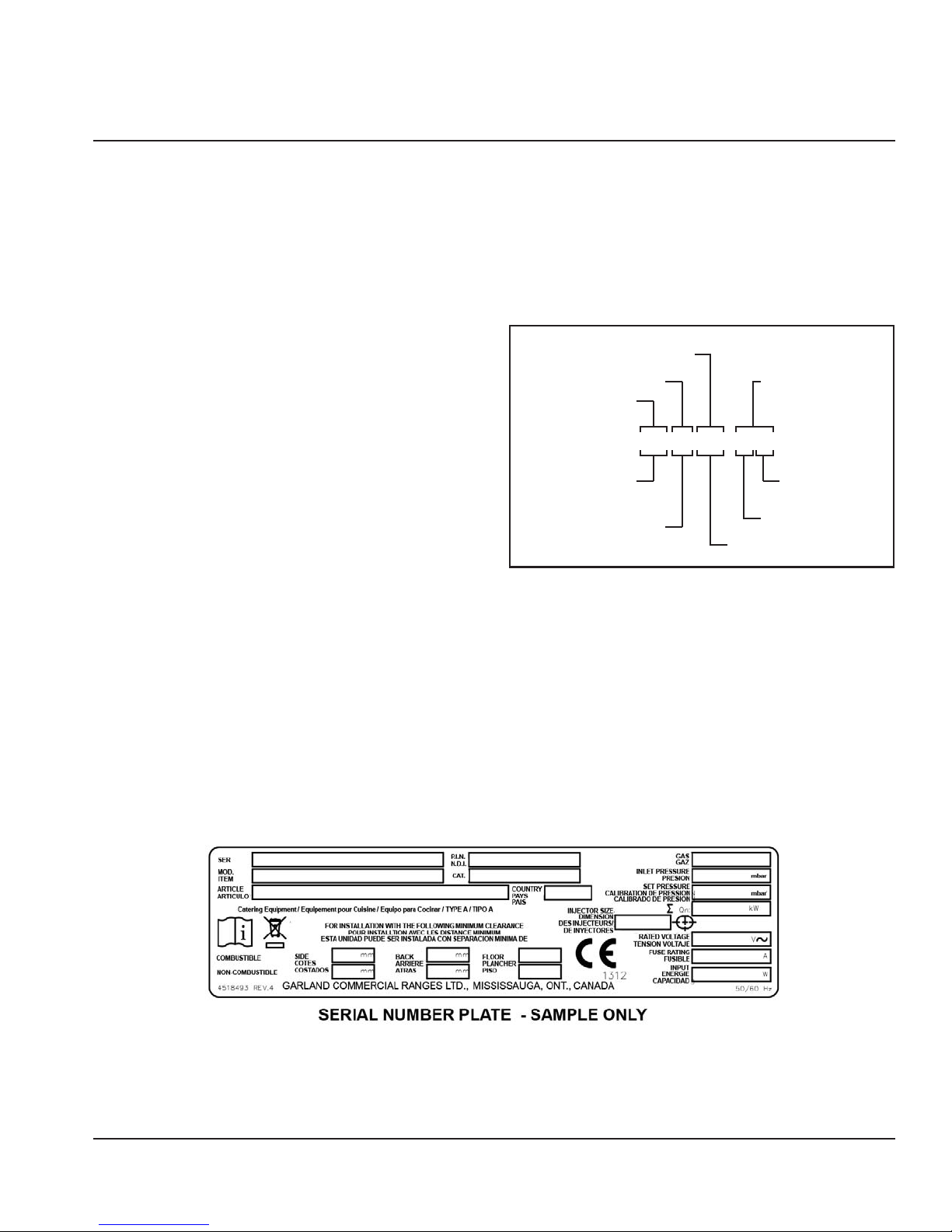
Serial Plate Numbers
The serial plate is affixed to the lower left corner of the
right panel and a serial sticker on front edge of the chassis.
Important information such as the unit’s model number,
serial number, and electrical/gas specifications can be
found on the serial plate. Serial plate is located is manual
covers the following models:
Document: GAR_SM_4601777 (4/16) 11
General Information Section 1
14
11
12913
15
3 PLATEN SHOWN
2 3
1
5
7
6
8
10
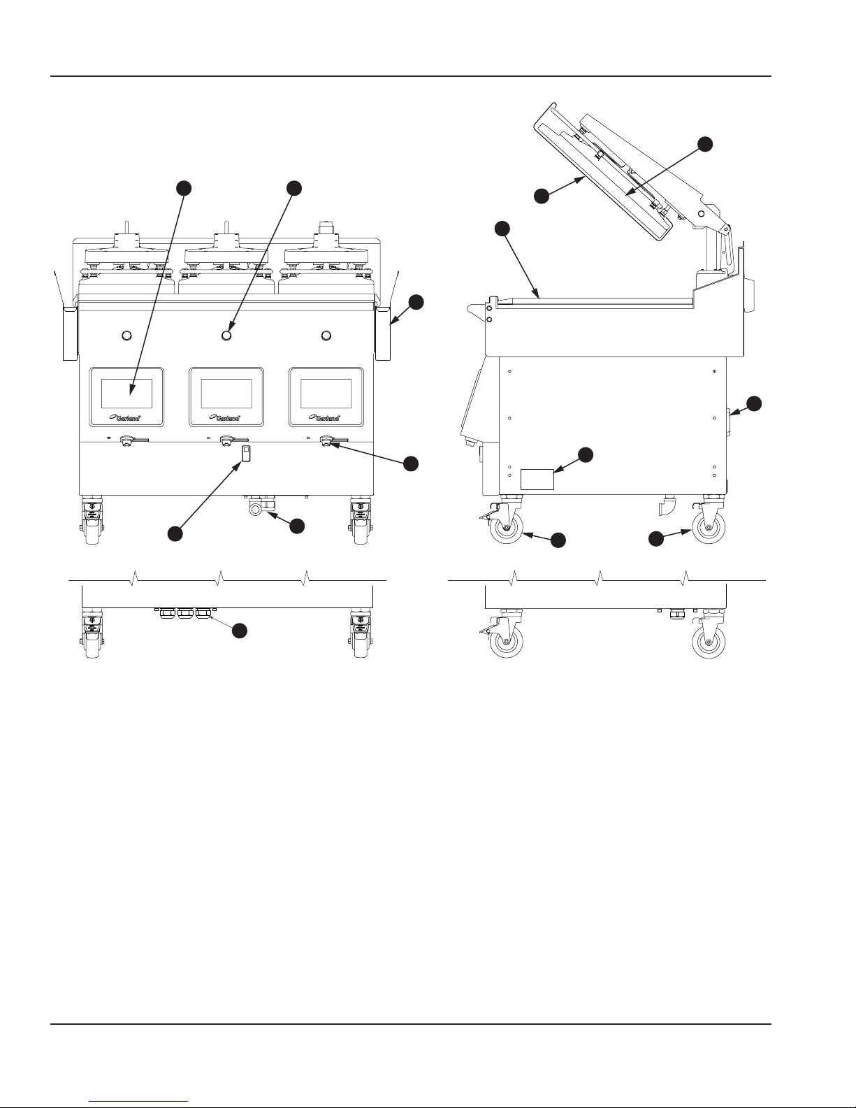
Main Features and Components
1. On/Off Power Switch
2. easyToUCH™ Touch sensitive controls for easy operation.
3. Green Push Button
• press to start cook
• press and hold to abort.
5. Platen - providing double-side cooking. Each platen can
be controlled separately.
6. Grill Plate - cooking surface with three (3) cook zones,
each zone can be controlled separately.
7. Release Material Sheet - non-stick surface for easy of
operation and cleaning.
12 Document: GAR_SM_4601777 (4/16)
8. Grease Buckets.
9. Front Casters - height adjustable swivel casters, with
brakes.
10. Rear Casters - height adjustable swivel casters, without
brakes.
11. USB Ports - for easyToUCH
12. Incoming gas manifold (gas models)
13. Circuit Breaker
14. Main Electric Power Cables and Plugs (electric models).
15. Rating Plate location. - important information such as
the unit’s model number, serial number, and electrical
specifications can be found on the serial plate.
Section 1 General Information
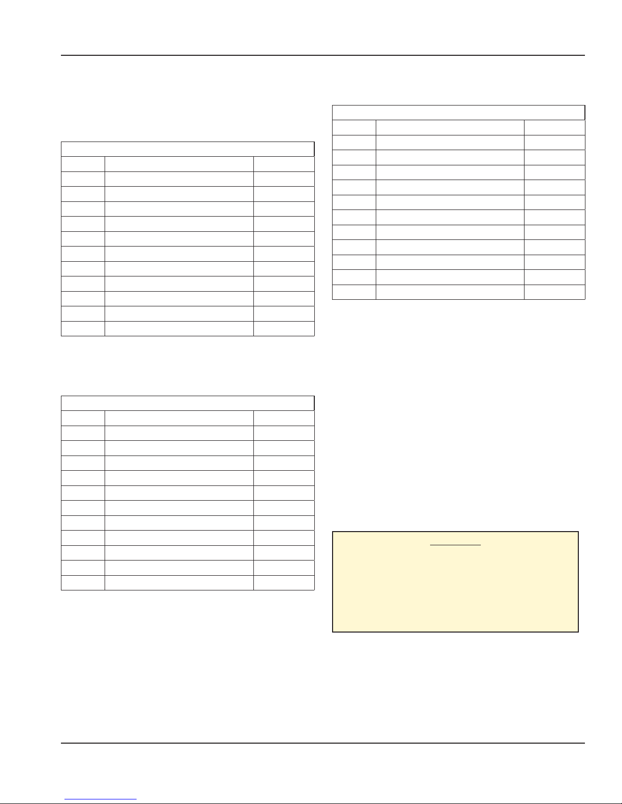
Items included with the purchase of your new
grill from manufacturer:
1. One Grill 1 platen gas & electric includes the
following list;
1 PLATEN
Part # Description Qty
4527294 Release Material Sheet Clips 3
4600722 Release Material Sheet Hanger 1
4600866 Release Material Sheet (box) 1
4600207 Grease Drawer Slide LT - GM 1
4600206 Grease Drawer Slide RT - GM 1
as speci ed
as speci ed
1838701
4532089
4601665
4532522
NOTE: Quantity may vary according to the model.
2. One Grill 2 platen gas & electric includes the
following list;
Part # Description Qty
4527294 Release Material Sheet Clips 6
4600722 Release Material Sheet Hanger 2
4600866 Release Material Sheet (box) 1
4600207 Grease Drawer Slide LT - GM 1
4600206 Grease Drawer Slide RT - GM 1
as speci ed
as speci ed
1838701
4532089
4601665
4532522
NOTE: Quantity may vary according to the model.
Grease Buckets - right side 1
Grease Buckets - left side 1
Platen Levelling Tool 1
Service Wrench 1
Garland Grill Start Up Form 1
Installation Operation Manual 1
2 PLATEN
Grease Buckets - right side 1
Grease Buckets - left side 1
Platen Levelling Tool 1
Service Wrench 1
Garland Grill Start Up Form 1
Installation Operation Manual 1
3. One Grill 3 platen gas & electric included the
following list, except countries mentioned
3 PLATEN
Part # Description Qty
4527294 Release Material Sheet Clips 9
4600722 Release Material Sheet Hanger 3
4600866 Release Material Sheet (box) 1
4600207 Grease Drawer Slide LT - GM 1
4600206 Grease Drawer Slide RT - GM 1
as speci ed
as speci ed
1838701
4532089
4601665
4532522
Grease Buckets - right side 1
Grease Buckets - left side 1
Platen Levelling Tool 1
Service Wrench 1
Garland Grill Start Up Form 1
Installation Operation Manual 1
NOTE: Quantity may vary according to the model.
Items NOT INCLUDED from the manufacturer:
1. Any electrical cords needed for application.
2. Any ue box needed for application.
3. Any extra grease buckets or grease rails needed for
application.
THE FOLLOWING INSTALLATION PROCEDURE
CAN BE PERFORMED BY A:
• Factory authorized service center
• An approved installation person approved by Garland.
• Licensed installer contracted by purchaser of grill.
• Contact local Garland Factory Authorized Service Center
for more details.
CAUTION:
PRIOR TO INSTALLATION, CHECK THE ELECTRICAL
SUPPLY TO ENSURE INPUT VOLTAGE AND PHASE
MATCH THE EQUIPMENT VOLTAGE RATING AND
PHASE. MANY LOCAL CODES EXIST, IT IS THE
RESPONSIBILITY OF THE OWNER/INSTALLER TO
COMPLY WITH THESE CODES.
Document: GAR_SM_4601777 (4/16) 13
General Information Section 1
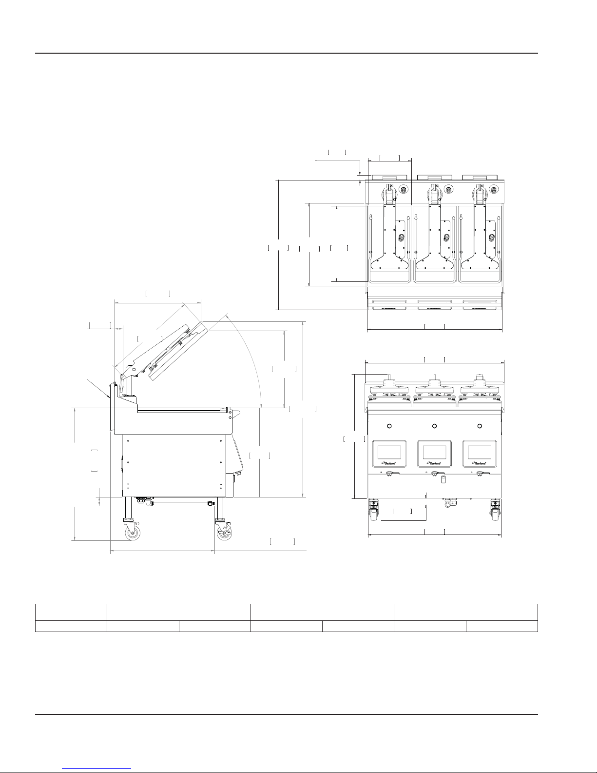
3 Platen Dimensions Specification
Dimensions: model: XP(E/G)36
1.255in
31.9mm
FOR GAS UNITS ONLY
TOP HEATER
11.500in
292.1mm
2.170in
55.1mm
FLUE BOX
FOR GAS
UNITS ONLY
59.9mm
FOR GAS UNITS ONLY
2.359in
[903.6 MAX TO 759.1 MIN]
35.574 MAX TO 29.887 MIN
25.250in
641.4mm
23.124in
587.4mm
MIN
22.000in
558.8mm
TOP HEATER
20.000in
508mm
32.941in
836.7mm
1.726in
43.8mm
FOR GAS UNITS ONLY
FRONT VIEW
GRILL PLATE
35.750in
908.1mm
TOP VIEW
36.979in
939.3mm
35.413in
899.5mm
GRILL PLATE
34.505in
876.4mm
42°
MAX
20.636in
524.1mm
MAX
47.212in
1199.2mm
MAX
23.978in
609mm
GAS CONNECTION
28.068in
712.9mm
FOR GAS UNITS ONLY
Model Height* Width** Depth
XP(E/G)24
* Height not including caster
** Without grease buckets.
32 in 812 mm 24 in 610 mm 34.5 in
14 Document: GAR_SM_4601777 (4/16)
876 mm

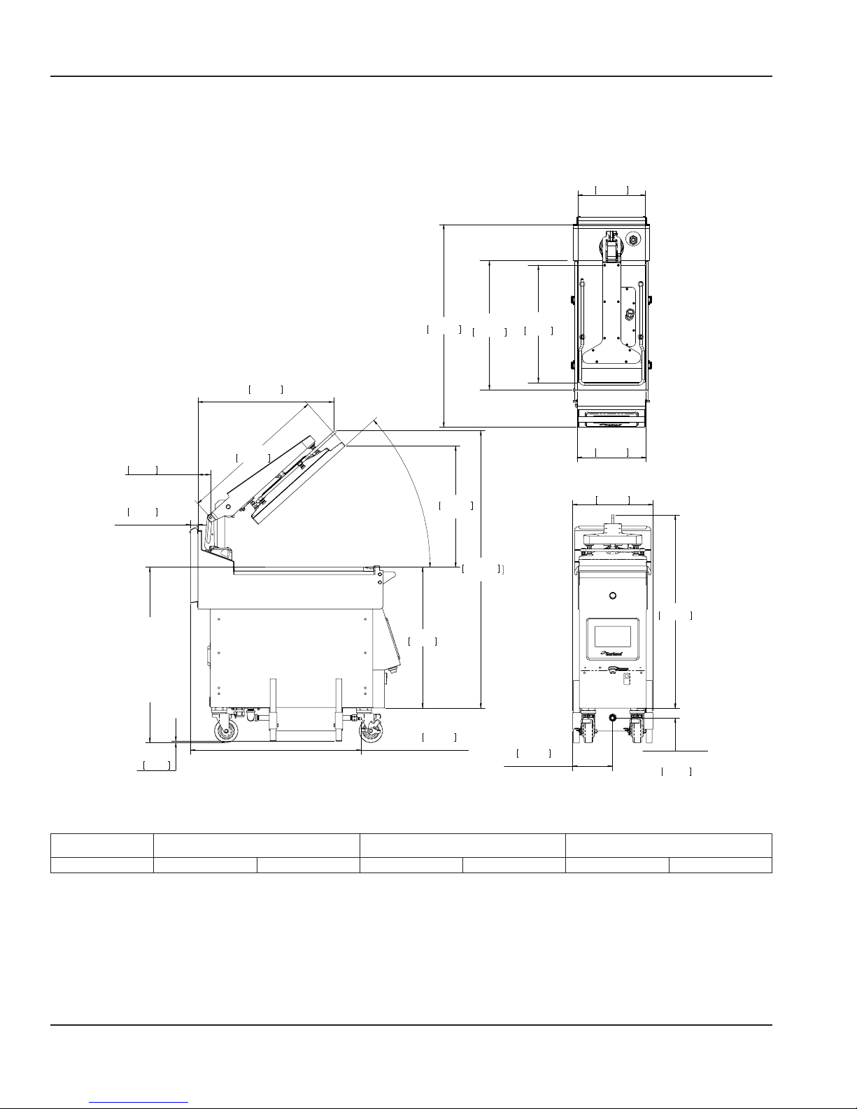
Section 1 General Information
2 Platen Dimensions Specification
Dimensions: model: XP(E/G)24
TOP HEATER
1.255in
31.9mm
FOR GAS UNITS ONLY
11.500in
292.1mm
2.170in
55.1mm
FLUE BOX
FOR GAS
UNITS ONLY
59.9mm
FOR GAS UNITS ONLY
2.359in
[903.6 MAX TO 759.1 MIN]
35.574 MAX TO 29.887 MIN
25.250in
641.4mm
23.124in
587.4mm
MIN
22.000in
MAX
FOR GAS UNITS ONLY
TOP HEATER
20.000in
508mm
32.941in
836.7mm
9.219in
234.2mm
GAS CONNECTION
GRILL PLATE
23.750in
603.3mm
TOP VIEW
24.979in
634.5mm
23.413in
594.7mm
FRONT VIEW
1.726in
43.8mm
FOR GAS UNITS ONLY
GRILL PLATE
34.505in
876.4mm
42°
MAX
23.978in
609mm
GAS CONNECTION
FOR GAS UNITS ONLY
20.636in
524.1mm
MAX
28.068in
712.9mm
558.8mm
47.212in
1199.2mm
Model Height* Width** Depth
XP(E/G)24
* Height not including caster
** Without grease buckets.
32 in 812 mm 24 in 610 mm 34.5 in
Document: GAR_SM_4601777 (4/16) 15
876 mm
General Information Section 1
1 Platen Dimensions Specification
Dimensions: model: XP(E/G)12
TOP HEATER
11.5in
292.1mm
2.2in
55.1mm
FLUE BOX
1.3in
31.8mm
(GAS UNITS ONLY)
[903.6 MAX TO 759.1 MIN]
35.574 MAX TO 29.887 MIN
25.3in
641.4mm
23.1in
587.4mm
MIN
22.0in
558.8mm
UPPER HEATER
20.0in
508mm
GRILL PLATE
11.8in
298.5mm
TOP VIEW
TOP VIEW
13.7in
348.1mm
32.9in
836.7mm
GRILL PLATE
34.5in
876.4mm
42°
MAX
20.6in
524.1mm
MAX
47.2in
1199.2mm
MAX
24.0in
609mm
ADJUST TO
0.25in
6.4mm
Model Height* Width** Depth
XP(E/G)12
* Height not including caster
** Without grease buckets.
32 in 812 mm 12 in 305 mm 34.5 in
16 Document: GAR_SM_4601777 (4/16)
GAS CONNECTION
29.1in
738.3mm
(GAS UNITS ONLY)
GAS CONNECTION
6.8in
172.3mm
GAS UNITS ONLY
FRONT VIEW
GAS CONNECTION
1.7in
42.2mm
(GAS UNITS ONLY)
876 mm
Section 1 General Information
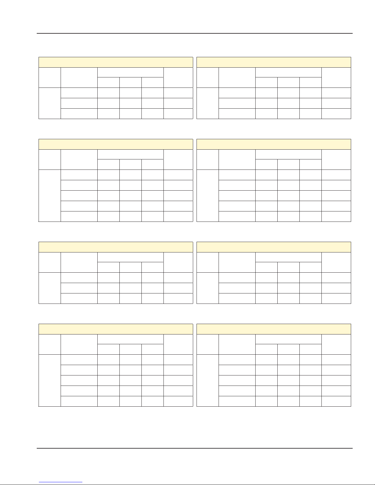
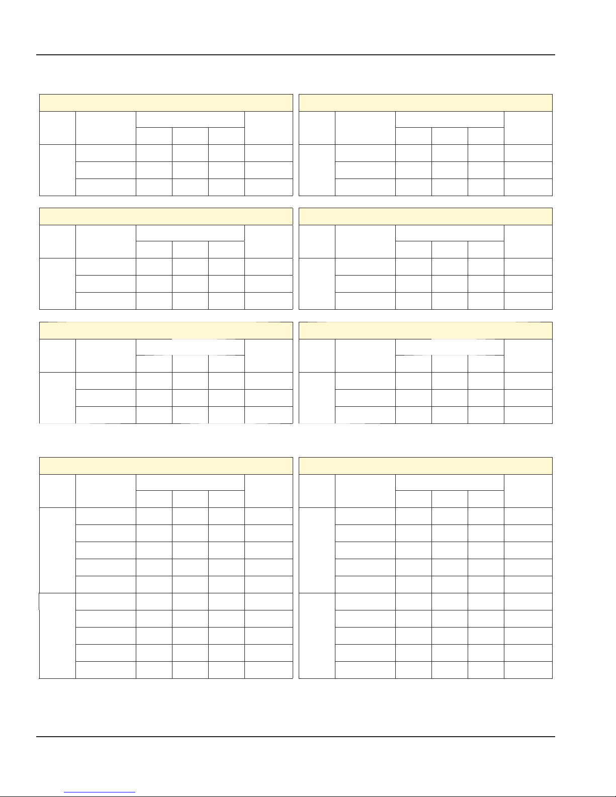
Electrical Input Specification - WYE (electric XPE-12 CE models)
Model
1
Platen
XPE-12 CE Models (electric models)
Volts
3NɎ(WYE)
50/60Hz
Total Current (A)
Power(kW)
L1 L2 L3
220V/380V 12.6 15.2 13.8 7.9
230V/400V 11.8 14.6 13.8 7.9
240V/415V 11.8 14.6 13.8 7.9
XPE-12 (0L,0R) CE Models (electric models)
Volts
Model
3NɎ(WYE)
50/60Hz
220V/380V 0.0 15.2 13.8 5.2
1
Platen
230V/400V 0.0 14.6 13.8 5.3
240V/415V 0.0 14.6 13.8 5.3
Electrical Input Specification - DELTA (electric XPE-12 models)
Model
1
Platen
XPE-12 Models (electric models)
Volts
3Ɏ(WYE)
50/60Hz
Total Current (A)
Power(kW)
L1 L2 L3
200V 23.6 26.5 25.8 8.0
208V 23.3 26.2 25.6 8.1
220V 22.0 23.7 24.1 7.9
230V 21.2 22.6 23.5 7.9
240V 21.0 22.5 23.4 7.9
Model
Platen
XPE-12 (0L,0R) Models (electric models)
Volts
3Ɏ(WYE)
50/60Hz
200V 13.9 16.8 25.8 5.3
208V 14.0 16.5 25.6 5.4
1
220V 13.8 15.2 24.1 5.2
230V 13.8 14.6 23.5 5.3
240V 13.8 14.6 23.4 5.3
Electrical Input Specification - WYE (gas XPG-12-CE models)
Total Current (A)
Power(kW)
L1 L2 L3
Total Current (A)
Power(kW)
L1 L2 L3
Model
XPG-12 CE Models (gas models)
Volts
3NɎ(WYE)
50/60Hz
Total Current (A)
L1 L2 L3
Power(kW)
Model
XPG-12 (0L,0R) CE Models (gas models)
220V/380V 12.6 4.7 0.0 3.4
1
Platen
230V/400V 11.8 4.7 0.0 3.4
1
Platen
240V/415V 11.8 4.7 0.0 3.4
Electrical Input Specification - DELTA (gas XPG-12 models)
XPG-12 Models (gas models)
Model
1
Platen
Volts
3Ɏ(WYE)
50/60Hz
200V 14.4 16.8 4.7 3.5
208V 14.0 16.5 4.8 3.5
220V 12.6 15.0 4.7 3.4
230V 11.8 14.2 4.7 3.4
240V 11.8 14.1 4.7 3.4
Total Current (A)
L1 L2 L3
Power(kW)
Model
1
Platen
Volts
3NɎ(WYE)
50/60Hz
Total Current (A)
Power(kW)
L1 L2 L3
220V/380V 0.0 4.7 0.0 0.8
230V/400V 0.0 4.7 0.0 0.8
240V/415V 0.0 4.7 0.0 0.8
XPG-12 (0L,0R) Models (gas models)
Volts
3Ɏ(WYE)
50/60Hz
Total Current (A)
Power(kW)
L1 L2 L3
200V 0.0 4.7 0.0 0.8
208V 0.0 4.8 0.0 0.8
220V 0.0 4.7 0.0 0.8
230V 0.0 4.7 0.0 0.8
240V 0.0 4.7 0.0 0.8
Document: GAR_SM_4601777 (4/16) 17
General Information Section 1
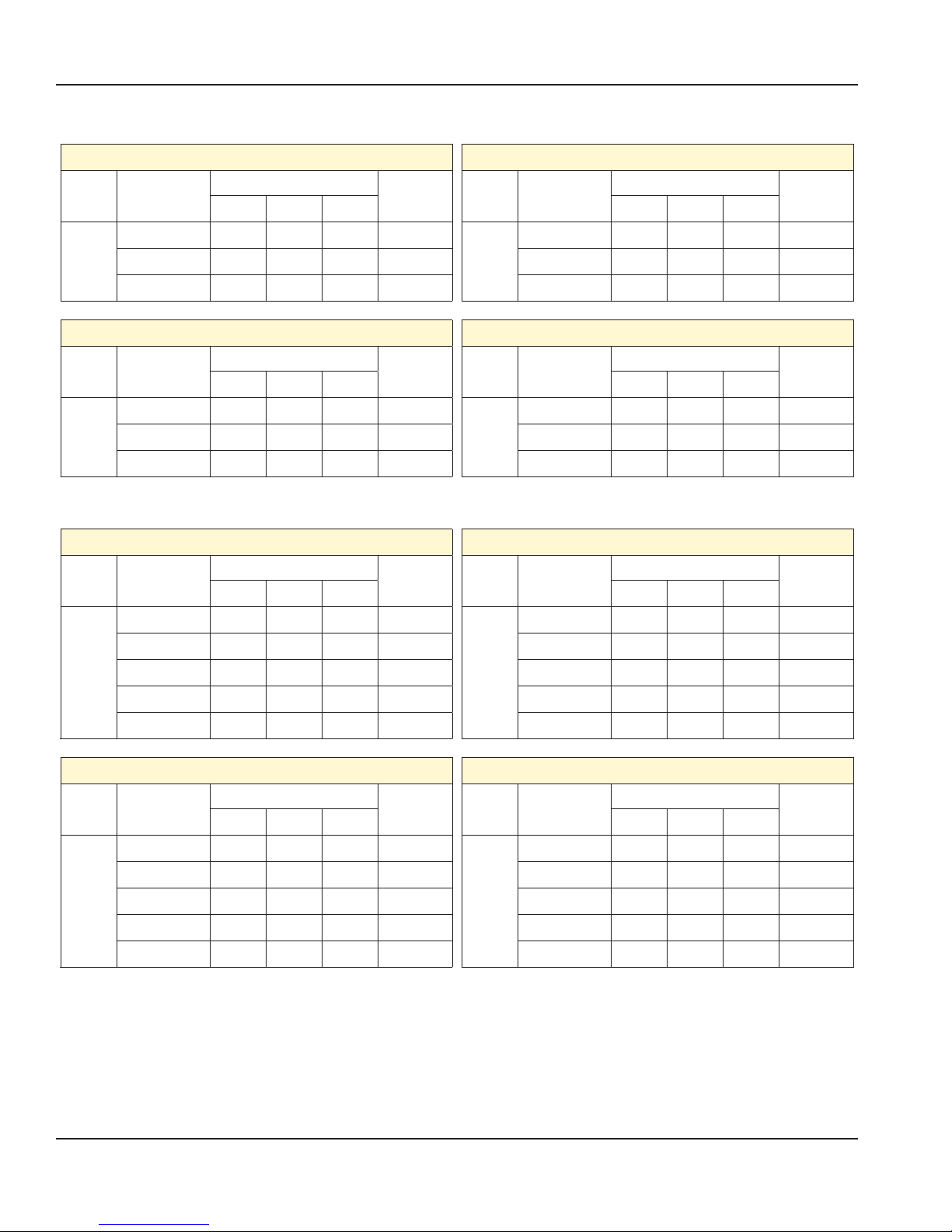
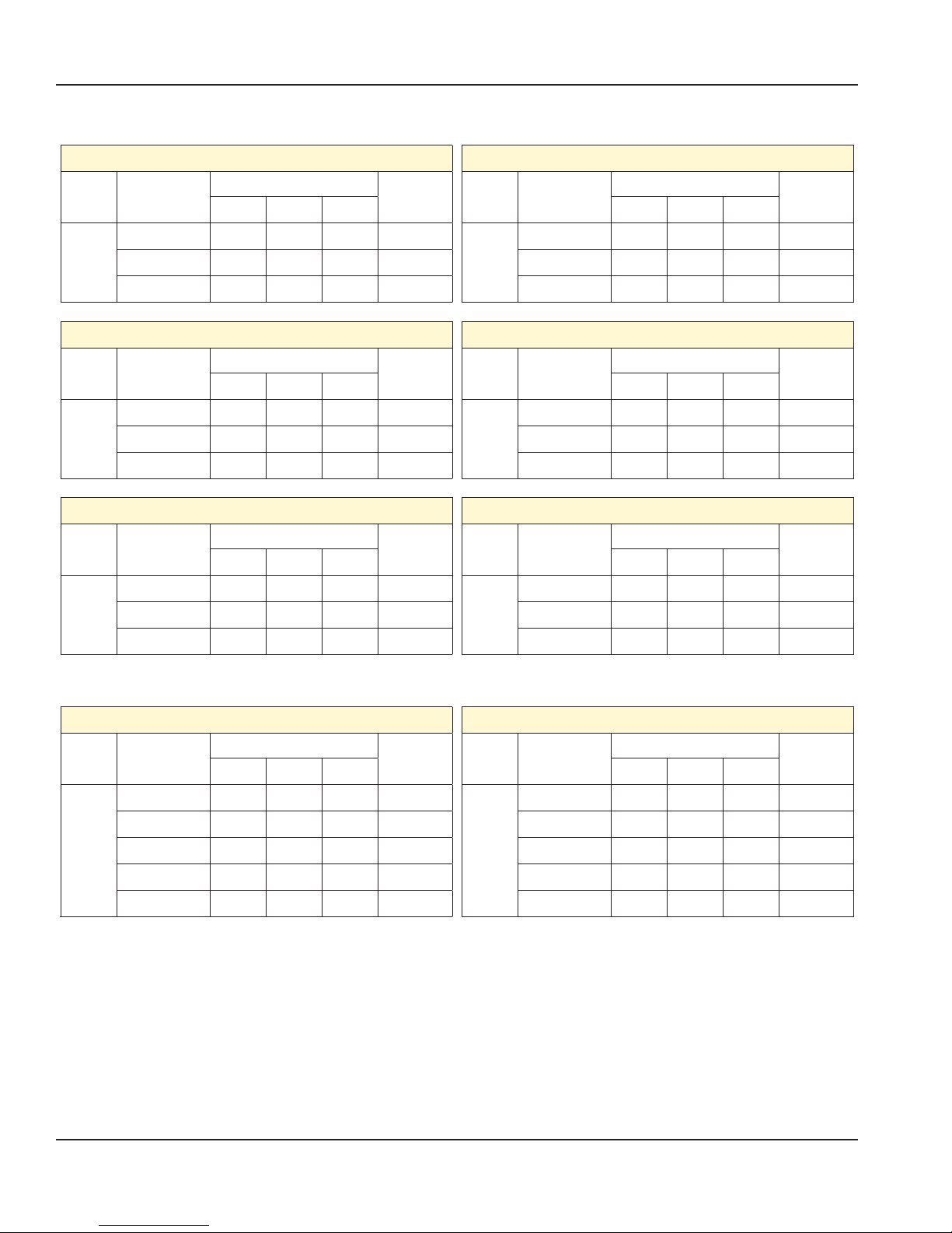
Electrical Input Specification - WYE (electric XPE-24 CE models)
Model
2
Platen
Model
2
Platen
XPE-24 CE Models (electric models)
Volts
3NɎ(WYE)
50/60Hz
Total Current (A)
Power(kW)
L1 L2 L3
220V/380V 27.3 24.9 27.1 15.8
230V/400V 26.4 23.9 25.8 15.9
240V/415V 26.4 23.7 25.8 15.9
XPE-24 1L CE Models (electric models)
Volts
3NɎ(WYE)
50/60Hz
Total Current (A)
Power(kW)
L1 L2 L3
220V/380V 27.3 13.8 2701 13.1
230V/400V 26.4 13.8 25.8 13.2
240V/415V 26.4 13.8 25.8 13.2
XPE-24 (0L,0R) CE Models (electric models)
Volts
Model
3NɎ(WYE)
50/60Hz
220V/380V 27.3 13.8 15.2 10.4
2
Platen
230V/400V 26.4 13.8 14.6 10.5
240V/415V 26.4 13.8 14.6 10.5
XPE-24 1R CE Models (electric models)
Volts
Model
3NɎ(WYE)
50/60Hz
220V/380V 27.3 24.9 15.2 13.1
2
Platen
230V/400V 26.4 23.9 14.6 13.2
240V/415V 26.4 23.7 14.6 13.2
Electrical Input Specification - DELTA (electric XPE-24 models)
Model
2
Platen
XPE-24 Models (electric models)
Volts
3Ɏ(WYE)
50/60Hz
Total Current (A)
Power(kW)
L1 L2 L3
200V 51.6 48.7 49.4 16.0
208V 50.8 48.1 48.4 16.2
220V 46.8 45.1 44.6 15.8
230V 44.9 43.9 42.8 15.9
240V 44.5 43.0 42.3 15.9
Model
Platen
XPE-24 (0L,0R) Models (electric models)
Volts
3Ɏ(WYE)
50/60Hz
200V 40.0 37.8 25.8 10.6
208V 39.6 37.5 25.6 10.8
2
220V 36.8 35.5 24.1 10.4
230V 35.7 35.1 23.5 10.5
240V 35.4 34.8 23.4 10.5
Total Current (A)
Power(kW)
L1 L2 L3
Total Current (A)
Power(kW)
L1 L2 L3
Total Current (A)
Power(kW)
L1 L2 L3
XPE-24 1L Models (electric models)
Model
Volts
3Ɏ(WYE)
50/60Hz
Total Current (A)
L1 L2 L3
200V 51.6 37.8 38.8 13.3
208V 50.8 37.5 38.1 13.5
2
Platen
220V 46.8 35.5 35.1 13.1
230V 44.9 35.1 33.7 13.2
240V 44.5 34.8 33.5 13.2
18 Document: GAR_SM_4601777 (4/16)
Power(kW)
Model
2
Platen
XPE-24 1R Models (electric models)
Volts
3Ɏ(WYE)
50/60Hz
Total Current (A)
Power(kW)
L1 L2 L3
200V 40.0 48.7 37.9 13.3
208V 39.6 48.1 37.1 13.5
220V 36.8 45.1 34.5 13.1
230V 35.7 43.9 33.3 13.2
240V 35.4 43.0 33.0 13.2

Section 1 General Information
Electrical Input Specification - WYE (gas XPG-24 CE models)
Model
XPG-24 CE Models (gas models)
Volts
3NɎ(WYE)
50/60Hz
Total Current (A)
L1 L2 L3
Power(kW)
Model
XPG-24 (0L,0R) CE Models (gas models)
220V/380V 4.7 12.6 16.7 6.8
2
Platen
230V/400V 4.7 11.8 15.5 6.9
2
Platen
240V/415V 4.7 11.8 15.6 6.9
XPG-24 1L CE Models (gas models)
Model
Volts
3NɎ(WYE)
50/60Hz
Total Current (A)
L1 L2 L3
Power(kW)
Model
220V/380V 4.7 0.0 16.7 4.2
2
Platen
230V/400V 4.7 0.0 15.5 4.2
2
Platen
240V/415V 4.7 0.0 15.6 4.2
Electrical Input Specification - DELTA (gas XPG-24 models)
XPG-24 Models (gas models)
Model
2
Platen
Volts
3Ɏ(WYE)
50/60Hz
200V 22.9 16.8 28.3 7.0
208V 20.5 16.5 27.6 7.0
220V 18.8 15.0 25.1 6.8
230V 18.0 14.2 23.7 6.9
240V 17.8 14.1 23.5 6.9
Total Current (A)
L1 L2 L3
Power(kW)
Model
2
Platen
Volts
3NɎ(WYE)
50/60Hz
Total Current (A)
Power(kW)
L1 L2 L3
220V/380V 4.7 0.0 4.7 1.5
230V/400V 4.7 0.0 4.7 1.5
240V/415V 4.7 0.0 4.7 1.5
XPG-24 1R CE Models (gas models)
Volts
3NɎ(WYE)
50/60Hz
Total Current (A)
Power(kW)
L1 L2 L3
220V/380V 4.7 12.6 4.7 4.2
230V/400V 4.7 11.8 4.7 4.2
240V/415V 4.7 11.8 4.7 4.2
XPG-24 (0L,0R) Models (gas models)
Volts
3Ɏ(WYE)
50/60Hz
Total Current (A)
Power(kW)
L1 L2 L3
200V 7.9 4.7 4.7 1.5
208V 8.0 4.8 4.8 1.6
220V 7.7 4.7 4.7 1.5
230V 7.7 4.7 4.7 1.5
240V 7.6 4.7 4.7 1.5
XPG-24 1L Models (gas models)
Model
Volts
3Ɏ(WYE)
50/60Hz
Total Current (A)
L1 L2 L3
200V 20.9 4.7 18.4 4.2
208V 20.5 4.8 18.0 4.3
2
Platen
220V 18.8 4.7 16.4 4.2
230V 18.0 4.7 15.6 4.2
240V 17.8 4.7 15.4 4.2
Document: GAR_SM_4601777 (4/16) 19
Power(kW)
Model
2
Platen
XPG-24 1R Models (gas models)
Volts
3Ɏ(WYE)
50/60Hz
Total Current (A)
Power(kW)
L1 L2 L3
200V 7.9 16.8 16.8 4.2
208V 8.0 16.5 16.5 4.3
220V 7.7 15.0 15.0 4.2
230V 7.7 14.2 14.2 4.2
240V 7.6 14.1 14.1 4.2
General Information Section 1
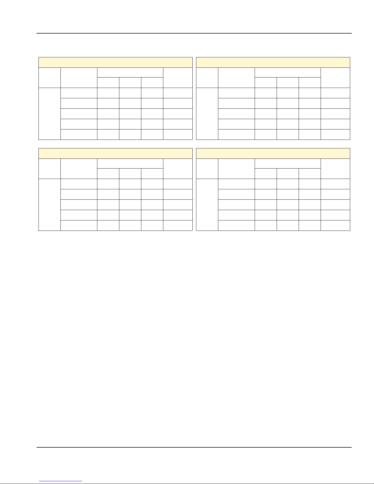
Electrical Input Specification - WYE (electric XPE-36 CE models)
Model
3
Platen
Model
3
Platen
Model
3
Platen
XPE-36 CE Models (electric models)
Volts
3NɎ(WYE)
50/60Hz
Total Current (A)
Power(kW)
L1 L2 L3
220V/380V 39.3 39.3 39.3 23.6
230V/400V 37.2 37.2 37.2 23.8
240V/415V 37.2 37.2 37.2 23.8
XPE-36 1L CE Models (electric models)
Volts
3NɎ(WYE)
50/60Hz
Total Current (A)
Power(kW)
L1 L2 L3
220V/380V 23.7 23.7 39.3 18.3
230V/400V 26.4 26.4 37.2 18.5
240V/415V 26.4 26.4 37.2 18.4
XPE-36 2L CE Models (electric models)
Volts
3NɎ(WYE)
50/60Hz
Total Current (A)
Power(kW)
L1 L2 L3
220V/380V 39.3 27.3 39.3 21.0
230V/400V 37.2 26.4 37.2 21.2
240V/415V 37.2 26.4 37.2 21.1
XPE-36 (0L,0R) CE Models (electric models)
Model
Volts
3NɎ(WYE)
50/60Hz
Total Current (A)
L1 L2 L3
220V/380V 27.3 27.3 27.3 15.7
3
Platen
230V/400V 26.4 26.4 26.4 15.8
240V/415V 26.4 26.4 26.4 15.8
XPE-36 1R CE Models (electric models)
Model
Volts
3NɎ(WYE)
50/60Hz
Total Current (A)
L1 L2 L3
220V/380V 27.3 39.3 27.3 18.3
3
Platen
230V/400V 26.4 37.2 26.4 18.5
240V/415V 26.4 37.2 26.4 18.4
XPE-36 2R CE Models (electric models)
Model
Volts
3NɎ(WYE)
50/60Hz
Total Current (A)
L1 L2 L3
220V/380V 39.3 39.3 27.3 21.0
3
Platen
230V/400V 37.2 37.2 26.4 24.2
240V/415V 37.2 37.2 26.4 21.1
Power(kW)
Power(kW)
Power(kW)
Electrical Input Specification - DELTA (electric XPE-36 models)
Model
3
Platen
Cord
1
3
Platen
Cord
2
XPE-36 Models (electric models)
Volts
3Ɏ(WYE)
50/60Hz
Total Current (A)
Power(kW)
L1 L2 L3
200V 25.8 23.6 26.5 16.0
208V 25.6 23.3 26.2 16.2
220V 23.7 22.0 24.1 15.8
230V 22.6 21.2 23.5 15.9
240V 22.5 21.0 23.4 15.9
200V 49.4 51.6 48.7 8.0
208V 48.4 50.8 48.1 8.1
220V 44.6 46.8 45.1 7.9
230V 42.8 44.9 43.9 7.9
240V 42.3 44.5 43.0 7.9
Model
Platen
Cord
Platen
Cord
XPE-36 (0L/R) Models (electric models)
Volts
3Ɏ(WYE)
50/60Hz
200V 25.8 13.9 16.8 5.3
3
208V 25.6 14.0 16.5 5.4
220V 24.1 13.8 15.2 5.2
1
230V 23.5 13.8 14.6 5.3
240V 23.4 13.8 14.6 5.3
200V 25.8 40.0 37.8 10.6
3
208V 25.6 39.6 37.5 10.8
220V 24.1 36.8 35.5 10.4
2
230V 23.5 35.7 35.1 10.5
240V 23.4 35.4 34.8 10.5
Total Current (A)
Power(kW)
L1 L2 L3
20 Document: GAR_SM_4601777 (4/16)

Section 1 General Information
Electrical Input Specification - DELTA (electric XPE-36models)
Model
3
Platen
Cord
1
3
Platen
Cord
2
Model
3
Platen
Cord
1
3
Platen
Cord
2
XPE-36 1L Models (electric models)
Volts
3Ɏ(WYE)
50/60Hz
Total Current (A)
Power(kW)
L1 L2 L3
200V 25.8 23.6 26.5 8.0
208V 25.6 23.3 26.2 8.1
220V 24.1 22.0 23.7 7.9
230V 23.5 21.2 22.6 7.9
240V 23.4 21.0 22.5 7.9
200V 25.8 40.0 37.8 10.6
208V 25.6 39.6 37.5 10.8
220V 24.1 36.8 35.5 10.4
230V 23.5 35.7 35.1 10.5
240V 23.4 35.4 34.8 10.5
XPE-36 2L Models (electric models)
Volts
3Ɏ(WYE)
50/60Hz
Total Current (A)
Power(kW)
L1 L2 L3
200V 13.9 16.8 25.8 5.3
208V 14.0 16.5 25.6 5.4
220V 13.8 15.2 24.1 5.2
230V 13.8 14.6 23.5 5.3
240V 13.8 14.6 23.4 5.3
200V 51.6 48.7 49.4 16.0
208V 50.8 48.1 48.4 16.2
220V 46.8 45.1 44.6 15.8
230V 44.9 43.9 42.8 15.9
240V 44.5 43.0 42.3 15.9
Model
3
Platen
Cord
1
3
Platen
Cord
2
Model
3
Platen
Cord
1
3
Platen
Cord
2
XPE-36 1R Models (electric models)
Volts
3Ɏ(WYE)
50/60Hz
Total Current (A)
Power(kW)
L1 L2 L3
200V 23.6 26.5 25.8 8.0
208V 23.3 26.2 25.6 8.1
220V 22.0 23.7 24.1 7.9
230V 21.2 22.6 23.5 7.9
240V 21.0 22.5 23.4 7.9
200V 40.0 37.8 25.8 10.6
208V 39.6 37.5 25.6 10.8
220V 36.8 35.5 24.1 10.4
230V 35.7 35.1 23.5 10.5
240V 35.4 34.8 23.4 10.5
XPE-36 2R Models (electric models)
Volts
3Ɏ(WYE)
50/60Hz
Total Current (A)
Power(kW)
L1 L2 L3
200V 25.8 13.9 16.8 5.3
208V 25.6 14.0 16.5 5.4
220V 24.1 13.8 15.2 5.2
230V 23.5 13.8 14.6 5.3
240V 23.4 13.8 14.6 5.3
200V 49.4 51.6 48.7 16.0
208V 48.4 50.8 48.1 16.2
220V 44.6 46.8 45.1 15.8
230V 42.8 44.9 43.9 15.9
240V 42.3 44.5 43.0 15.9
Document: GAR_SM_4601777 (4/16) 21
General Information Section 1
Electrical Input Specification - WYE (gas XPG-36 CE models)
Model
3
Platen
Model
3
Platen
Model
3
Platen
XPG-36 CE Models (gas models)
Volts
3NɎ(WYE)
50/60Hz
Total Current (A)
Power(kW)
L1 L2 L3
220V/380V 16.7 16.7 16.7 10.2
230V/400V 15.5 15.5 15.5 10.3
240V/415V 15.6 15.6 15.6 10.3
XPG-36 1L CE Models (gas models)
Volts
3NɎ(WYE)
50/60Hz
Total Current (A)
Power(kW)
L1 L2 L3
220V/380V 4.7 4.7 16.7 4.9
230V/400V 4.7 4.7 15.5 5.0
240V/415V 4.7 4.7 15.6 5.0
XPG-36 2L CE Models (gas models)
Volts
3NɎ(WYE)
50/60Hz
Total Current (A)
Power(kW)
L1 L2 L3
220V/380V 16.7 4.7 16.7 7.6
230V/400V 15.5 4.7 15.5 7.7
240V/415V 15.6 4.7 15.6 7.6
Model
3
Platen
Model
3
Platen
Model
3
Platen
XPG-36 (0L/R) CE Models (gas models)
Volts
3NɎ(WYE)
50/60Hz
Total Current (A)
Power(kW)
L1 L2 L3
220V/380V 4.7 4.7 4.7 2.3
230V/400V 4.7 4.7 4.7 2.3
240V/415V 4.7 4.7 4.7 2.3
XPG-36 1R CE Models (gas models)
Volts
3NɎ(WYE)
50/60Hz
Total Current (A)
Power(kW)
L1 L2 L3
220V/380V 4.7 16.7 4.7 4.9
230V/400V 4.7 15.5 4.7 5.0
240V/415V 4.7 15.6 4.7 5.0
XPG-36 2R CE Models (gas models)
Volts
3NɎ(WYE)
50/60Hz
Total Current (A)
Power(kW)
L1 L2 L3
220V/380V 16.7 16.7 4.7 7.6
230V/400V 15.5 15.5 4.7 7.7
240V/415V 15.6 15.6 4.7 7.6
Electrical Input Specification - DELTA (gas XPG-36 models)
XPG-36 Models (gas models)
Model
3
Platen
Volts
3Ɏ(WYE)
50/60Hz
200V 31.7 31.7 31.7 10.4
208V 30.9 30.9 30.9 10.6
220V 28.3 28.3 28.3 10.2
230V 27.3 27.3 27.3 10.3
240V 26.1 26.1 26.1 10.3
Total Current (A)
L1 L2 L3
Power(kW)
Model
3
Platen
XPG-36 (0L/R) Models (gas models)
Volts
3Ɏ(WYE)
50/60Hz
Total Current (A)
Power(kW)
L1 L2 L3
200V 7.0 7.0 7.0 2.3
208V 6.9 6.9 6.9 2.3
220V 6.3 6.3 6.3 2.3
230V 6.1 6.1 6.1 2.3
240V 5.8 5.8 5.8 2.3
22 Document: GAR_SM_4601777 (4/16)
Section 1 General Information
Electrical Input Specification - DELTA (gas XPG-36 models), continuation
Model
3
Platen
Model
3
Platen
XPG-36 1L Models (gas models)
Volts
3Ɏ(WYE)
50/60Hz
Total Current (A)
Power(kW)
L1 L2 L3
200V 20.6 7.0 20.6 5.0
208V 20.1 6.9 20.1 5.1
220V 18.4 6.3 18.4 4.9
230V 17.8 6.1 17.8 5.0
240V 17.0 5.8 17.0 5.0
XPG-36 2L Models (gas models)
Volts
3Ɏ(WYE)
50/60Hz
Total Current (A)
Power(kW)
L1 L2 L3
200V 31.7 20.6 20.6 7.7
208V 30.9 20.1 20.1 7.8
220V 28.3 18.4 18.4 7.6
230V 27.3 17.8 17.8 7.7
240V 26.1 17.0 17.0 7.6
Model
3
Platen
Model
3
Platen
XPG-36 1R Models (gas models)
Volts
3Ɏ(WYE)
50/60Hz
Total Current (A)
Power(kW)
L1 L2 L3
200V 7.0 20.6 20.6 5.0
208V 6.9 20.1 20.1 5.1
220V 6.3 18.4 18.1 4.9
230V 6.1 17.8 17.8 5.0
240V 5.8 17.0 17.0 5.0
XPG-36 2R Models (gas models)
Volts
3Ɏ(WYE)
50/60Hz
Total Current (A)
Power(kW)
L1 L2 L3
200V 20.6 31.7 20.6 7.7
208V 20.1 30.9 20.1 7.8
220V 18.4 28.3 18.4 7.6
230V 17.8 27.3 17.8 7.7
240V 17.0 26.1 17.0 7.6
Document: GAR_SM_4601777 (4/16) 23
General Information Section 1
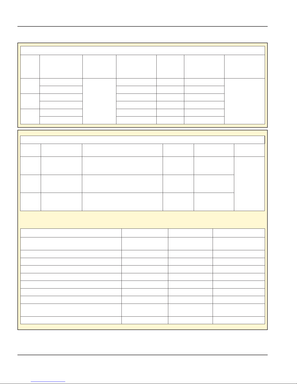
Gas Input Specification
Gas Grills, 1, 2 & 3 Platen North America - all CSA models.
GAS
1
Platen
2
Platen
3
Platen
Input Speci cation - All CE Models.
GAS
GROUP
G20 2.93
G31 2.93
NATURAL GAS
PROPANE 20,000 1.2mm 11.0” WC
NATURAL GAS 40,000 1.5mm 7.0” WC
PROPANE 40,000 1.2mm 11.0” WC
NATURAL GAS 60,000 1.5mm 7.0” WC
PROPANE 60,000 1.2mm 11.0” WC
MAX INPUT NET
PER BURNER kW
MAX INPUT
NET PER
BURNER
BTU/H
10,000
TOTAL INPUT RATING kW
5.86kW - (For XPE12 series)
11.72kW - (For XPE24 series)
17.58kW - (For XPE36 series)
5.86kW - (For XPE12 series)
11.72kW - (For XPE24 series)
17.58kW - (For XPE36 series)
5.86kW - (For XPE12 series)
11.72kW - (For XPE24 series)
17.58kW - (For XPE36 series)
TOTAL INPUT
RATING
BTU/H
20,000 1.5mm 7.0” WC
INJECTOR
SIZE
INJECTOR
SIZE mm
SUPPLY PRESSURE
IN W.C.
PRESSURE mbar
1.5mm
1.5mm
1.2mm
BURNER
10mbar
(4.0” WC)
13.7mbar
(5.5” WC)
10mbar
(4.0” WC)
BURNER MANIFOLD
PRESSURE
IN W.C.
4.0” WC
FAN SPEED
SETTING (RPM)
10,000G25 2.93
For G31 propane gas, the unit has been set at the factory for a 37mbar supply pressure. A factory authorized service
technician must adjust the unit if a 30mbar supply pressure is used.
COUNTRY GAS CATEGORY GAS TYPE SUPPLY PRESSURE (mbar)
AT, CH, CY, CZ, DK, EE, ES, FI, FR, GB, GR, HR, IE, IT, LT, LU,
LV, NL, NO, PT, RO, SE, SI, SK, TR
HU I2H G20 25
DE, LU, PL, RO I2E G20 20
BE I2E(R) G20 20
FR I2E(r) G20/G25 20/25
FR, NL I2L G25 25
RO I2L G25 20
FI, HU,NL, RO I3P G31 30
BE, CH, CZ, ES, FR, GB, GR, HU, IE, IT, LT, NL, PL, PT, SI, SK,
HR
AT, BE, CH, CZ, DE, ES, FR, GB, GR, HU, NL, SK I3P G31 50
I2H G20 20
I3P G31 37
NOTE: For installations up to 2000ft. units being installed at higher elevation must be configured accordingly at the factory
or modified at the installation site by a factory authorized service technician.
24 Document: GAR_SM_4601777 (4/16)
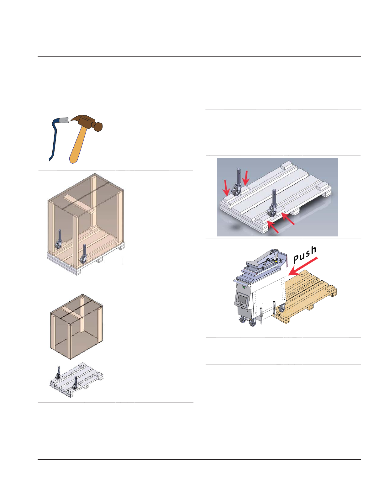
STOP! - Follow the instructions below to safely and easily remove unit from packaging skid.
Unit very heavy Personal Protective Equipment (PPE) required.
Removing Grill From Wood Crate
Tools required.
1. PACKAGING
Section 2
Installation
IS DIVIDED IN
TWO PARTS,
CARDBOARD
BOX AND THE
WOOD SKID.
3. REMOVE AND DISCARD THE TWO (2) WOOD
BLOCKS LOCKING EACH OF THE FRONT CASTER.
NOTE: ENSURE FRONT CASTER BRAKES ARE ON
WHILE BLOCK ARE BEEN REMOVED.
4.
2. REMOVE AND
DISCARD THE
CARDBOARD BOX
COVERING THE UNIT.
Document: GAR_SM_4601777 (4/16)
5. RELEASE THE FRONT CASTER BRAKES AND PUSH
UNIT FORWARD OFF OF THE SKID. ENSURE THAT
THE UNIT ROLLS STRAIGHT AS IT IS BEING MOVED.
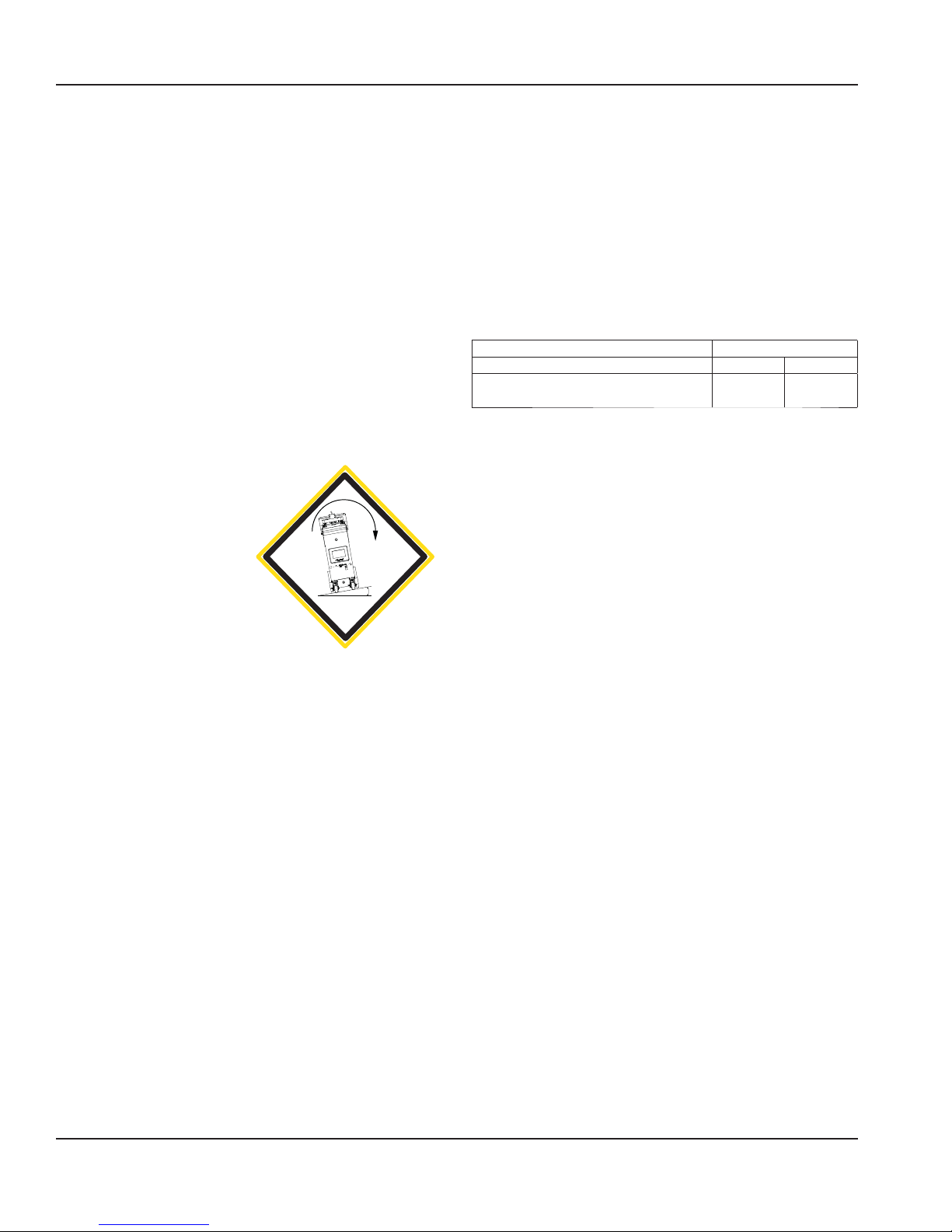
Installation Section 2
Transporting Grill To Location
Transporting your new grill to the kitchen requires the
following criteria.
• Plan first before anything else. Lower your risk of
encountering problems during the transport process.
• Understand brake caster mechanism to apply or release
when requires.
• Keep top platen down during transportation.
• Match transportation speed to conditions.
• Turn downhill, not uphill, if stability becomes uncertain
on slope or ramp.
• Push/pull the grill by the towel bar straight even with
the gentle slope.
• Do not push/pull diagonally across it.
• Do not push/pull by conduit or platen arm.
• One (1) platen model is
narrow, take extra care
for slope and ramp. If
slope or ramp is greater
than ±100 there is
potential that the grill
will tip-over, ask for
10
Ý
help and use the proper
techniques transporting
the grill.
Location
The location selected for the equipment must meet the
following criteria. If any of these criteria are not met, select
another location.
• The location MUST be level and capable of supporting
the weight of the equipment:
→ 3platen - 238.1 kg (525 lbs) approximately.
→ 2platen - 165.6 kg (365 lbs) approximately.
→ 1platen - 154.2 kg (340 lbs) approximately.
• The location MUST be free from and clear of
combustible materials.
• Equipment MUST be level both front to back and side to
side.
• Position the equipment so it will not tip or slide.
• The air temperature must be at least 40°F (4.4°C) must
not exceed 110°F (43.3°C).
• Proper air supply for ventilation is REQUIRED AND
CRITICAL for safe and efficient operation. Refer to
Clearance Requirements chart.
• Do not obstruct the flow of ventilation air. Make sure the
air vents of the equipment are not blocked
• The location must not be near heat-generating (broiler,
dishwashers, etc) equipment or in direct sunlight and
must be protected from weather.
• Do not install the equipment directly over a drain.
Steam rising up out of the drain will adversely affect
operation, air circulation, and damage electrical /
electronic components.
• Do not store anything on top of a unit.
Clearance Requirements
Entry Installation
Uncrated Sides Rear
32" x 35.8" x 31.4"*
(812 mm x 909 mm x 798 mm)
* Depth 31.4” (798 mm), with towel bar and front panel removed
2"
(51 mm)4"(102 mm)
Leveling
Position the unit under the hood and in its normal
operational position to prevent warping of the grill plate &
optimize cooking performance.
• Adjust the unit by turning the casters clockwise to raise
the unit and counterclockwise to lower the unit.
• Adjust the casters until the grill plate is level and at the
proper height.
• Grill must be level front to back, side to side and
diagonally. This leveling must be done with the unit
under the hood and it’s normal operation.
• Tighten the lock nut on each caster tightly against the
bottom of the unit.
• When the unit is in place, lock the front casters to
prevent movement.
• Lock the casters from swiveling to facilitate moving the
unit straight in and out for cleaning.
Exhaust Hood Requirements
1. Install the equipment under an Exhaust Hood.
2. The exhaust hood must extend over the exhaust ports
and meet the following requirements:
A. The exhaust hood must be sized for the cumulative
ventilation requirements of all the appliances in
the area under the hood.
B. If an existing hood cannot be used, a new one
must be constructed over the equipment.
C. When determining hood size; include clearances.
NOTE: Always turn ON the exhaust hood when the unit is
running to prevent condensation in the unit.
26 Document: GAR_SM_4601777 (4/16)
Section 2 Installation
Ventilation
Hood
25.4
1.00
Min.
Platen
Clearance between Platen and Hood
Positioning
The unit is very heavy and mechanical assistance may be
required to lift and position the appliance.
The unit is designed to be installed on a smooth and
level floor built to withstand the weight of the fully laden
appliance.
The unit is pre-installed with casters for ease of mobility for
cleaning and servicing. Take proper care to push or pull the
grill and ensure the grill does not tip over.
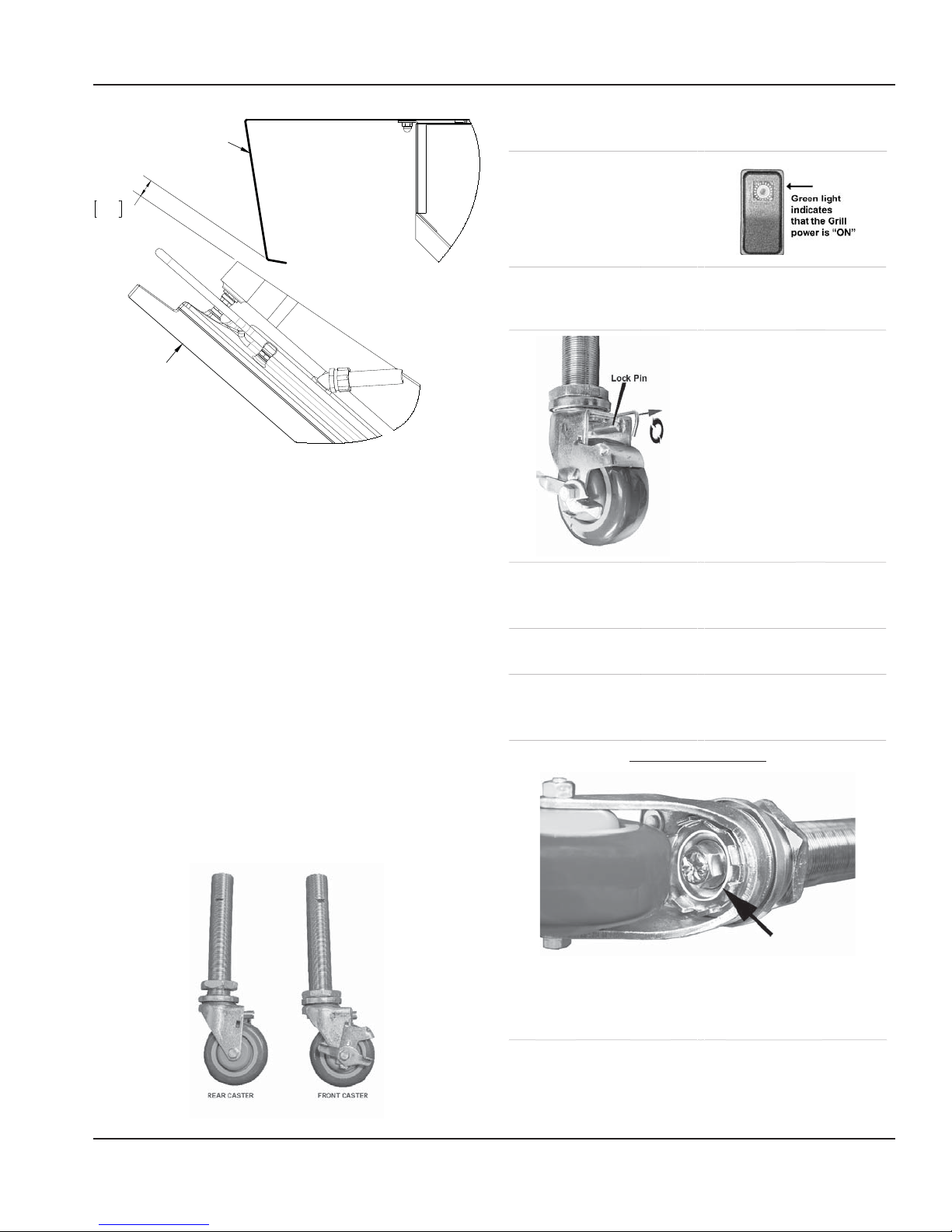
Casters Adjustment Procedure
1. Turn the clamshell grill
Green Power Main Switch
OFF. (green light o )
2. Rear and front Casters have a threaded stem to
adjust the level of the grill independent of the swiveling
action.
3. All casters are
adjustable.
4. Lock the caster swivel
using the locking pin.
Pull the clip and turn 90
degrees, release pin. (Note:
applying the locking pin in
the lock position will lock
the swivel of the caster
assembly).
5. Carefully raise the unit slightly so that the wheel is
o the ground and no longer bearing unit weight.
6. Loosen caster jam nut by turning it counterclockwise
with a wrench.
Appliances Equipped with Casters
The unit is shipped with casters installed in place, some
adjustment may be required to level the unit. The front
and rear casters are adjustable, only the front casters have
brakes.
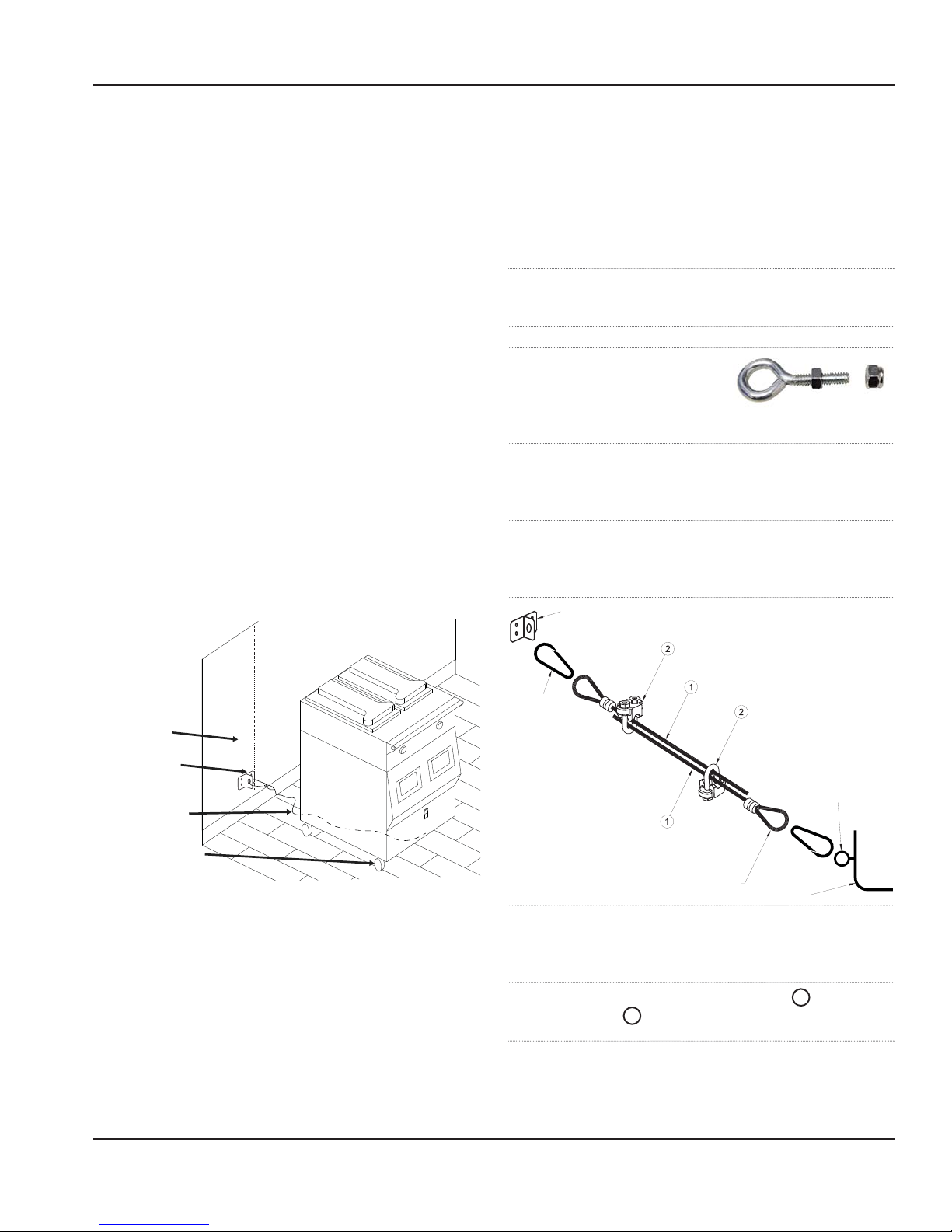
Garland recommends installing restraining chains/cables
from the floor/wall to the rear of the unit. These restraints
limit the mobility of the appliance.
7. Adjust the caster assembly by turning the caster
(swivel locking pin on) counterclockwise to increase the
height or clockwise to decrease the height.
IMPORTANT NOTE
On the caster assembly shown above there is a nut used
to assemble the swivel system - do not use wrench on
this nut. This nut is intended for the caster swiveling
system only.
Document: GAR_SM_4601777 (4/16) 27
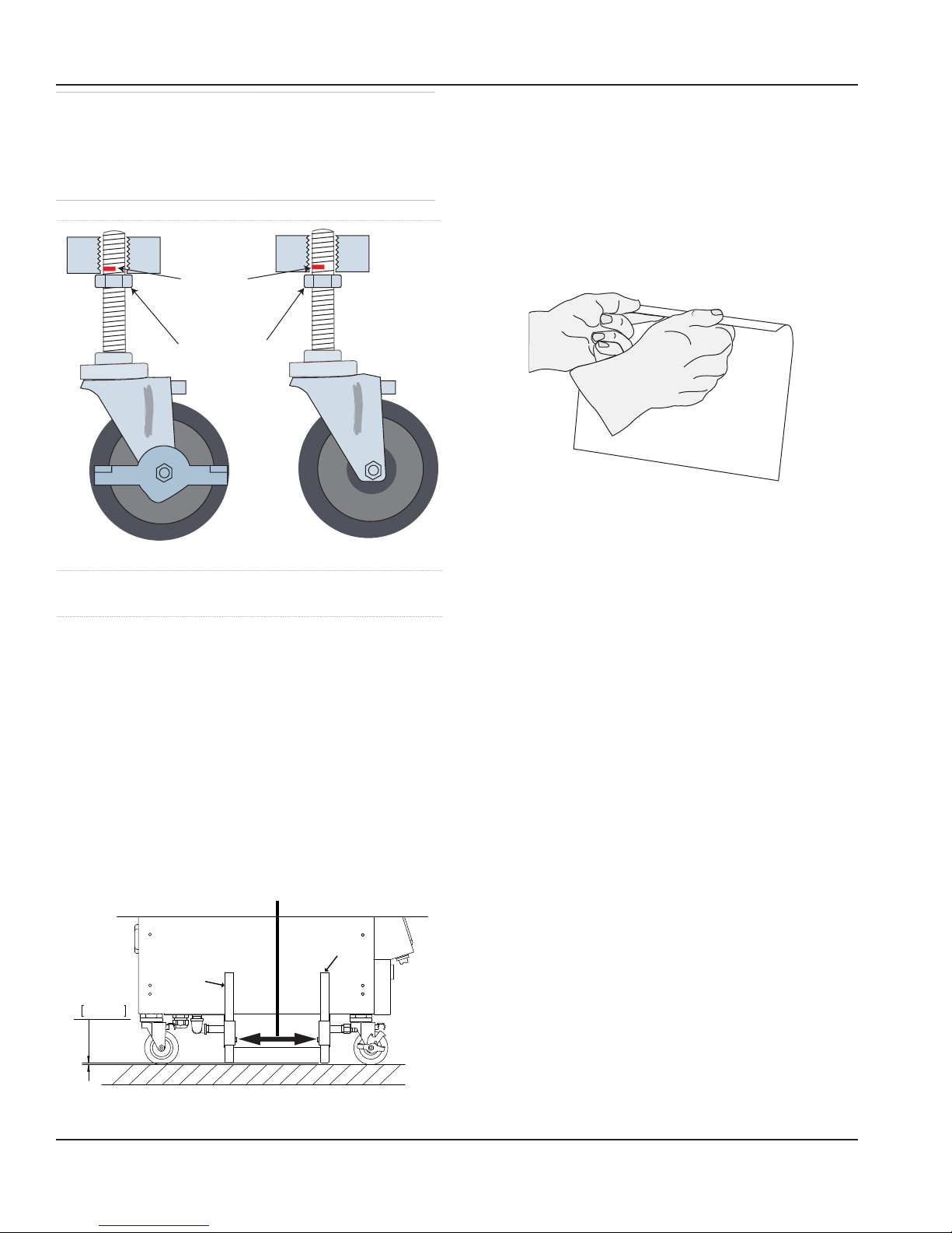
Installation Section 2
8. Beware of the red mark in the threaded stem to
indicated the maximum adjustment. Red mark in the
threaded stem portion should not be visible.
Warning: Adjusting above the red mark could cause the
caster to fail & the unit to tip.
Red Mark in Shaft
Should
NOT be Visible
Caster Jam Nuts
FRONT CASTER WITH BRAKE REAR CASTER WITHOUT BRAKE
9. After the grill is completely level, tighten caster jam
nut to secure the caster assembly.
Securing Stabilizer Grill System (1 platen models only)
Stabilizer system will help prevent the grill from tippingover within a range of 00 to 100 degrees angle perpendicular
to the front of the unit.
1. Proceed and complete Caster Adjustment Procedure as
mentioned above.
2. Lower the stabilizing arms, (total of four (4) arms
located beside the side panels) until the arms touch the
floor.
3. Raise each arm 0.25” (6.4mm) off the floor and secure
the arm with the bolt on the side of each arm, as shown
below.
Tight bolts to secure arm in place
total of four (4) bolts
Remove Stainless Steel Plastic Film Cover
Removing this film is one of the things that must be done
once the Grill is in place. The film covers both internal and
external components (e.g. side panels, grease shield) and
must be removed before turning the grill on.
1. Using a plastic scraper, wedge the film away from the
stainless steel.
2. Grasp and pull the film very gently away from the
stainless steel.
PEEL OFF PLASTIC FILM
Temporary Storage
Garland provides adequate protection under normal
conditions in transit and storage. The grill may need
additional protection if it is stored near salt water, a tropical
area, or other unfavorable conditions. Please contact
Garland immediately if these conditions occur.
Gas Connector Requirements:
• Installation shall be made with the gas connector
that has been supplied loose with the grill. The quick
disconnect fitting and gas shut off valve must be
installed in the direction indicated on their outer body.
• NOTE: When checking gas pressure, be sure that all
other equipment on the same gas line is on.
• The appliance and its individual shut-off valve must be
disconnected from the gas supply piping system during
any pressure testing of that system pressures in excess
of ½ PSIG (3.45kPa).
• Adequate clearance must be provided for servicing and
proper operation.
Stabilizer Arm
ADJUST TO
0.25in
6.4mm
Stabilizer Arm
NOTE: UNDER NO CIRCUMSTANCES SHOULD YOU
REMOVE THE STABILIZER SYSTEM FROM GRILL.
28 Document: GAR_SM_4601777 (4/16)
National Codes Requirements:
• The type of gas for which the grill is equipped is
stamped on the serial plate mounted on the lower left
corner of the right panel. Connect a grill to the gas type
stamped on the data plate only.
• The installation must conform to the National Fuel Gas
Code ANSI Z223.1-1998 or latest edition, NFPA No. 54 –
latest edition and National Electrical Code ANSI/NFPA
70-1990 or latest edition and/or local code to assure
safe and efficient operation. In Canada, the installation
Section 2 Installation
must comply with CSA B149.1 and local codes where
applicable.
• In Canada, electrical connection must comply with
applicable sections of the Canadian Electrical Code,
C22.1 - 1990, latest edition, “Safety Standard for
Installation, Part 1” and C22.2- No. O-M 1982 latest
edition.
Installation store responsibilities:
• The installation shall be made with a connector that
complies with the Standard for Connectors for Moveable Gas Appliances, ANSI Z21.69/CSA 6.16, and quickdisconnect device that complies with the Standard for
Quick Disconnect Devices for Use with Gas Fuel, ANSI
Z21.41/CSA 6.9.
• The front Casters on the appliance are equipped with
brakes to limit the movement of the appliance without
placing any strain on the connector or quick disconnect
device or its associated piping.
• Please be aware: required restraint is attached to a
bracket, (which is located on the front of the grill,
underneath, closest to the gas connection) and if
disconnection of the restraint is necessary, be sure
to reconnect the device after the appliance has been
returned to its original position.
• Conduct training with your crew personnel to ensure
maximum utilization of the grill. Once the installation
is complete as per the procedures below, a factory
authorized service company MUST startup the grill
according to Garland Commercial Ranges startup
standards.
Restraining device installation Procedure
1. Shutoff main gas line valve and disconnect the quickdisconnect gas line device before the following
installation .
2. Attach the bracket to a stud in the wall.
3. Locate the area in the
frame on front of the grill
underneath, to place the
eye-bolt. Closest to the gas
connection
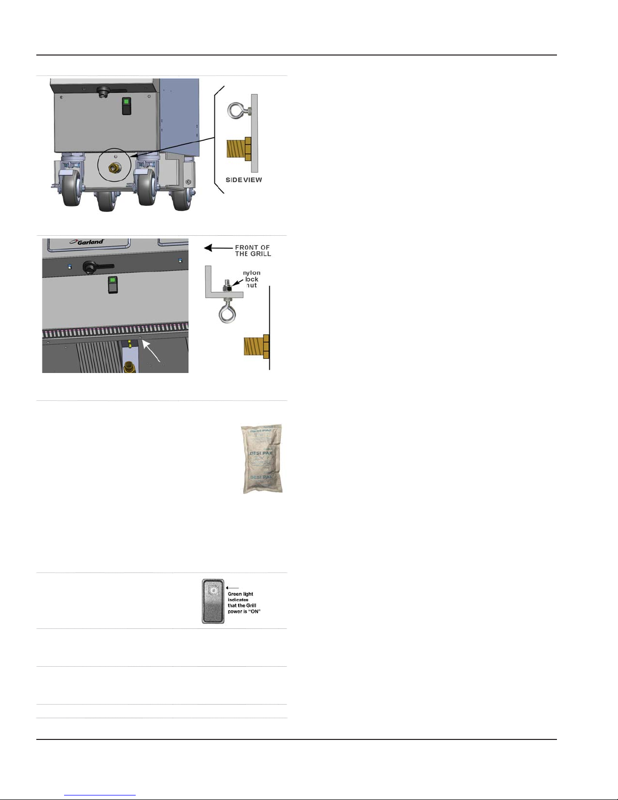
4. For model one (1) platen grill gas. Discard nylon
lock nut of the eye-bolt and screw it underneath
of the front panel above the gas line (Figure
A), tighten eye-bolt jam nut to secure it in place.
5. For model two & three (2&3) platen grill gas. Slide
the eye-bolt through the hole and place the nylon
lock nut on the inside frame and tighten securely
(Figure B).
attached to the wall
spring loaded
hook
STUD
BLOCKING SECURE
TO CONCRETE WALL
OR STUD
RESTRAINING CABLE
FRONT CASTER WITH
BRAKE TO SECURE GRILL
• “Adequate clearance must be provide for air opening
into the combustion chamber, and for proper servicing”
• Not intended to be installed adjacent to combustible
walls or on combustible floors.
• Ensure grill has been installed by a competent trained
installation person.
• Ensure store readiness of utilities, product & personnel.
loop
appliance
6. Attach one of the spring-loaded hook to the bracket
on the wall and the other end to the eye-bolt (grill).
adjust the proper distance of the cable 1 and tight
both clamps 2 to secure the both cables
7. Test straining cable by moving the grill, movement of
the grill must not place any strain on the connector or
quick disconnect device or its associated piping.
eye-bolt
• Contacting your local Garland Factory Authorized
Service Center for a startup date.
• Participate in the startup to ensure a successful startup
and familiarity with the grill.
Document: GAR_SM_4601777 (4/16) 29
Installation Section 2
Gas Connections, and Pipe Sizing:
• The size of the gas line is very important. If the line is too
small, the gas pressure at the burner manifold will be
low. This will cause slow recovery and delayed ignition.
The incoming gas pressure line should be a minimum of
1-1/2”. All grills require a 3/4” connection.
• Before connecting new pipe the pipe must be blown
out to dispose of any foreign particles. These particles
will cause improper operation.
• When using thread compound, use small amounts on
male threads only. Use a compound that is not affected
Figure A - one (1) platen
Figure B - two & three (1&2) platen
“Desi Pak” bags from the grill:
• Desi Pak bags are only intended to be
left inside the grill during shipment and
equipment storage. Desi Pak are designed
to protect the electronic components
by controlling humidity levels within the
equipment.
• Garland highly recommends these bags remain in
the equipment while the grills are in storage or not in
operation
Removing “Desi Pak” bags from the grill:
1. Turn the clamshell grill
Green Power Main Switch OFF.
(green light o )
2. Remove the two phillip screws located on each side of
the front panel below the user interface and store them in
a save place.
3. Gently slightly move the panel up and then away
from the grill, be very careful with the wires and
connectors. Remove the bags.
4. Reinstall cover and tighten the screws.
by the chemical action of LP gases. Avoid applying
compound to the first two threads to prevent clogging
of the burner orifices and control valve.
• Have the installer check all gas plumbing with a soap
solution for leaks. DO NOT USE matches, candles or
other ignition sources in checking for leaks.
• Check the data plate to determine the proper type of
gas before connecting the quick disconnect or piping
from the building gas supply.
• An incoming gas pressure test nipple is provided on the
incoming gas manifold for pressure checks.
• Minimum incoming gas pressure for Natural Gas is 6”
W.C. Maximum incoming gas pressure for Natural Gas is
14” W.C.
• Minimum incoming gas pressure for Propane is 10” W.C.
Maximum incoming gas pressure for Propane is 26” W.C.
• Burner operating gas pressure can be checked at the
outlet side of the gas valve at the pressure test point.
• Refer to “Gas Input Specification Chart” for correct
burner manifold pressure based on gas type.
• To adjust the burner pressure, remove the sealing screw
from the pressure test nipple, connect a manometer,
remove the sealing cap on the gas valve regulator, turn
on the grill, adjust the screw in the regulator to give
the correct pressure, turn off the grill, refit the regulator
sealing cap, remove the manometer, replace the seal
screw in the test nipple and test for gas leaks.
• Gas pressures should be checked by the local Gas
Company or an authorized service agency only.
• Test all piping and connections for gas leaks. A rich soap
solution should be used for this purpose. Never use a
flame
• The appliance must be isolated from the gas supply
piping system by closing its individual manual
shutoff valve during any pressure testing of the gas
supply piping system at test pressures equal to or
less than ½ psi (3.5 kPa).
30 Document: GAR_SM_4601777 (4/16)
 Loading...