

Garland XE362S-2L Service Manual
SERVICE MANUAL
GAS & ELECTRIC
XPRESS GRILLS
FOR SONIC
MODEL NUMBERS:
XG36S, XG362S-L, XE36S, XE362S-2L
FOR YOUR SAFETY:
DO NOT STORE OR USE GASOLINE
OR OTHER FLAMMABLE VAPORS OR
LIQUIDS IN THE VICINITY OF THIS OR ANY OTHER
APPLIANCE
WARNING:
IMPROPER INSTALLATION, ADJUSTMENT,
ALTERATION, SERVICE OR MAINTENANCE CAN
CAUSE PROPERTY DAMAGE, INJURY, OR DEATH.
READ THE INSTALLATION,
OPERATING AND MAINTENANCE
INSTRUCTIONS THOROUGHLY
BEFORE INSTALLING OR
SERVICING THIS EQUIPMENT
NOTE:
THIS MANUAL PERTAINS TO ALL XPRESS GRILL
MODELS LISTED ABOVE. THE READER/OPERATOR
MUST INTERPRET ITS CONTENTS TO APPLICABLE
NEEDS. HOWEVER, IF THERE IS ANY QUESTION OF
INTERPRETATION OF ANY LITERATURE PERTAINING
TO GARLAND GRILLS, PLEASE CONTACT OUR
CUSTOMER SERVICE DEPARTMENT AT ONE OF THE
PHONE NUMBERS LISTED BELOW.
PLEASE READ ALL SECTIONS OF THIS MANUAL AND
RETAIN FOR FUTURE REFERENCE.
THIS PRODUCT HAS BEEN CERTIFIED AS COMMERCIAL
COOKING EQUIPMENT AND MUST BE INSTALLED BY
PROFESSIONAL PERSONNEL AS SPECIFIED.
CAUTION: THIS EQUIPMENT MUST ONLY BE OPERATED
UNDER AN APPROVED HOOD SYSTEM
IN THE COMMONWEALTH OF MASSACHUSETTS
THIS PRODUCT MUST BE INSTALLED BY A LICENSED
PLUMBER OR GAS FITTER.
For Your Safety:
Post in a prominent location, instructions to be
followed in the event the user smells gas. This
information shall be obtained by consulting your local
gas supplier.
GARLAND COMMERCIAL INDUSTRIES, LLC
185 East South Street
Freeland, Pennsylvania 18224
Phone: (570) 636-1000
Fax: (570) 636-3903
SSM09 (03/11/10) © 2009 Garland Commercial Industries, LLC
SSM09 (03/11/10) Page 1
GARLAND COMMERCIAL RANGES, LTD.
1177 Kamato Road, Mississauga, Ontario L4W 1X4
CANADA
Phone: 905-624-0260
Fax: 905-624-5669

TABLE OF CONTENTS
DIMENSIONS AND SPECIFICATIONS, . . . . . . . . . . . 4
INTRODUCTION . . . . . . . . . . . . . . . . . . . . . . . . . . . . . . 5
Warranty . . . . . . . . . . . . . . . . . . . . . . . . . . . . . . . . . . . . . . . . . . . . . . 5
Shipping Damage Claim Procedure. . . . . . . . . . . . . . . . . . . . . 5
SAFETY . . . . . . . . . . . . . . . . . . . . . . . . . . . . . . . . . . . . . . 5
INSTALLATION. . . . . . . . . . . . . . . . . . . . . . . . . . . . . . . . 7
Rating Plate Location . . . . . . . . . . . . . . . . . . . . . . . . . . . . . . . . . . 7
General Information . . . . . . . . . . . . . . . . . . . . . . . . . . . . . . . . . . . 7
National Codes Requirements: . . . . . . . . . . . . . . . . . . . . . . . . . 7
Gas Connections, and Pipe Sizing: . . . . . . . . . . . . . . . . . . . . . . 7
Appliances Equipped with Casters: . . . . . . . . . . . . . . . . . . . . . 8
Electrical Connections: . . . . . . . . . . . . . . . . . . . . . . . . . . . . . . . . . 8
Accessory Kit – Main Gas Inlet:. . . . . . . . . . . . . . . . . . . . . . . . . . 8
Accessory Kit – Electrical Supply Lines:. . . . . . . . . . . . . . . . . . 9
Electrical Connection Terminal Block Connection . . . . . .10
Grease Bucket:. . . . . . . . . . . . . . . . . . . . . . . . . . . . . . . . . . . . . . . .10
Ventilation and Clearance:. . . . . . . . . . . . . . . . . . . . . . . . . . . . .10
Changing to a dierent type of gas . . . . . . . . . . . . . . . . . . . .11
Burner Air Adjustment . . . . . . . . . . . . . . . . . . . . . . . . . . . . . . . .11
Igniter Adjustment. . . . . . . . . . . . . . . . . . . . . . . . . . . . . . . . . . . .11
GRILL CONTROLS . . . . . . . . . . . . . . . . . . . . . . . . . . . . 12
Master Power Switch: . . . . . . . . . . . . . . . . . . . . . . . . . . . . . . . . .12
LED Indicators:. . . . . . . . . . . . . . . . . . . . . . . . . . . . . . . . . . . . . . . .12
Display: . . . . . . . . . . . . . . . . . . . . . . . . . . . . . . . . . . . . . . . . . . . . . .12
Product Buttons (0-9): . . . . . . . . . . . . . . . . . . . . . . . . . . . . . . . . .12
Power Button: . . . . . . . . . . . . . . . . . . . . . . . . . . . . . . . . . . . . . . . . 12
Program Button: . . . . . . . . . . . . . . . . . . . . . . . . . . . . . . . . . . . . . .13
Temperature Button:. . . . . . . . . . . . . . . . . . . . . . . . . . . . . . . . . .13
Up/Down Arrow Buttons; 2 Functions: . . . . . . . . . . . . . . . . 13
Enter Button: . . . . . . . . . . . . . . . . . . . . . . . . . . . . . . . . . . . . . . . . .13
Cancel/Raise Platen Button, (Green): . . . . . . . . . . . . . . . . . .13
Black Button: . . . . . . . . . . . . . . . . . . . . . . . . . . . . . . . . . . . . . . . . .13
Main Pre-Programed Product Items. . . . . . . . . . . . . . . . . . . .13
PLATEN ZEROING . . . . . . . . . . . . . . . . . . . . . . . . . . . . 14
OPTIONAL ACCESSORIES. . . . . . . . . . . . . . . . . . . . . 16
NORMAL OPERATION . . . . . . . . . . . . . . . . . . . . . . . . 18
Installing Release Material: . . . . . . . . . . . . . . . . . . . . . . . . . . . .18
Lighting Instructions: . . . . . . . . . . . . . . . . . . . . . . . . . . . . . . . . .18
Shut Down Instructions . . . . . . . . . . . . . . . . . . . . . . . . . . . . . . .18
Simplied Cook Cycle Instructions: . . . . . . . . . . . . . . . . . . . .18
To Cook in Two-Sided Mode: . . . . . . . . . . . . . . . . . . . . . . . . . .19
To Cook in Flat Grill Mode:. . . . . . . . . . . . . . . . . . . . . . . . . . . . .19
Enter Standby Mode:. . . . . . . . . . . . . . . . . . . . . . . . . . . . . . . . . .19
Exit Standby Mode: . . . . . . . . . . . . . . . . . . . . . . . . . . . . . . . . . . . 19
To Display the Current Temperatures: . . . . . . . . . . . . . . . . . . 20
To View Settings for a Menu Item:. . . . . . . . . . . . . . . . . . . . . .20
To Clean the Grill: . . . . . . . . . . . . . . . . . . . . . . . . . . . . . . . . . . . . .20
PLATEN SET: . . . . . . . . . . . . . . . . . . . . . . . . . . . . . . . . . . . . . . . . . .20
EXTENDED TIME: . . . . . . . . . . . . . . . . . . . . . . . . . . . . . . . . . . . . . . 20
INSTANT ON TIME: . . . . . . . . . . . . . . . . . . . . . . . . . . . . . . . . . . . .20
START DELAY: . . . . . . . . . . . . . . . . . . . . . . . . . . . . . . . . . . . . . . . . .20
CLEANING AND MAINTENANCE . . . . . . . . . . . . . . 20
Cleaning During Operation: . . . . . . . . . . . . . . . . . . . . . . . . . . . 20
Daily Cleaning:. . . . . . . . . . . . . . . . . . . . . . . . . . . . . . . . . . . . . . . .21
PROGRAMMING . . . . . . . . . . . . . . . . . . . . . . . . . . . . . 22
Programming Modes/Menu Sequence: . . . . . . . . . . . . . . . .22
Menu Items...
To Change the Cook Time of a Product: . . . . . . . . . . . . . . . .24
To Turn Platen, (2-Sided), Cooking On/O: . . . . . . . . . . . . .24
To Change Upper Platen Set Temperature: . . . . . . . . . . . . .24
To Change Grill Set Temperature: . . . . . . . . . . . . . . . . . . . . . . 24
To Change Product Gap Setting:. . . . . . . . . . . . . . . . . . . . . . . 24
To Change Product Button, “Key” Assignment . . . . . . . . . .25
To Change a Product Name: . . . . . . . . . . . . . . . . . . . . . . . . . . .25
System Info...
To View Recovery Time - Upper Platen:. . . . . . . . . . . . . . . . .25
To View Recovery Time - Grill:. . . . . . . . . . . . . . . . . . . . . . . . . .25
To View the Garland Part Number: . . . . . . . . . . . . . . . . . . . . .25
To View the Flash Number: . . . . . . . . . . . . . . . . . . . . . . . . . . . .26
To View the Software Number:. . . . . . . . . . . . . . . . . . . . . . . . .26
To View the Download Number: . . . . . . . . . . . . . . . . . . . . . . .26
RELEASE MATERIAL INSTALLATION . . . . . . . . . . . 17
SSM09 (03/11/10)Page 2

TABLE OF CONTENTS continued
System Setup
To Change temperature Units, (°F or °C): . . . . . . . . . . . . . . .26
To Change Gap Setting Display Units:. . . . . . . . . . . . . . . . . .26
To Change the Alarm Volume: . . . . . . . . . . . . . . . . . . . . . . . . .27
To Change the Key Chirp:. . . . . . . . . . . . . . . . . . . . . . . . . . . . . .27
To Change Probe Calibration - Upper:. . . . . . . . . . . . . . . . . .27
To Change Probe Calibration - Grill:. . . . . . . . . . . . . . . . . . . .27
To Change Platen Set: . . . . . . . . . . . . . . . . . . . . . . . . . . . . . . . . . 28
To Change Instant-On Time:. . . . . . . . . . . . . . . . . . . . . . . . . . .28
To Change Control Type: . . . . . . . . . . . . . . . . . . . . . . . . . . . . . . 28
To Turn Extended Time On/O: . . . . . . . . . . . . . . . . . . . . . . . . 28
To Change the Grill Function:. . . . . . . . . . . . . . . . . . . . . . . . . .29
To Change the Start Delay: . . . . . . . . . . . . . . . . . . . . . . . . . . . .29
To Change the Alarm Mode:. . . . . . . . . . . . . . . . . . . . . . . . . . .29
To Turn Clean Mode On/O: . . . . . . . . . . . . . . . . . . . . . . . . . . . 29
To Add a Product Name in Library:. . . . . . . . . . . . . . . . . . . . . 29
To Modify a Product Name in Library: . . . . . . . . . . . . . . . . . .30
Service Mode
To Change SCK Address:. . . . . . . . . . . . . . . . . . . . . . . . . . . . . . . 30
To Perform Limit Switch Test: . . . . . . . . . . . . . . . . . . . . . . . . . . 30
CALIBRATION. . . . . . . . . . . . . . . . . . . . . . . . . . . . . . . . 31
Bi-Weekly Calibration:. . . . . . . . . . . . . . . . . . . . . . . . . . . . . . . . .31
Probe Locations: . . . . . . . . . . . . . . . . . . . . . . . . . . . . . . . . . . . . . .32
TROUBLESHOOTING . . . . . . . . . . . . . . . . . . . . . . . . . 33
ERROR MESSAGES:
PROBE ERROR: . . . . . . . . . . . . . . . . . . . . . . . . . . . . . . . . . . . . . . . .33
PLATEN DOWN ERROR:. . . . . . . . . . . . . . . . . . . . . . . . . . . . . . . .33
PLATEN UP ERROR:. . . . . . . . . . . . . . . . . . . . . . . . . . . . . . . . . . . .33
HEATING ERROR: . . . . . . . . . . . . . . . . . . . . . . . . . . . . . . . . . . . . . .33
COMM ERROR: . . . . . . . . . . . . . . . . . . . . . . . . . . . . . . . . . . . . . . . .33
MOTOR OVER CURRENT:. . . . . . . . . . . . . . . . . . . . . . . . . . . . . . .33
MOTOR ERROR: . . . . . . . . . . . . . . . . . . . . . . . . . . . . . . . . . . . . . . .33
IGNITION ERROR:. . . . . . . . . . . . . . . . . . . . . . . . . . . . . . . . . . . . . .33
FLASHING LED(S):. . . . . . . . . . . . . . . . . . . . . . . . . . . . . . . . . . . . .33
TECHNICAL TROUBLESHOOTING . . . . . . . . . . . . . 34
Master Power (ON / OFF) Switch turned ON -
Power light or indicator is not lit . . . . . . . . . . . . . . . . . . . . . . .34
Low Internal Product Temperatures. . . . . . . . . . . . . . . . . . . .34
Controller Displays “Too Hot” . . . . . . . . . . . . . . . . . . . . . . . . . .35
Controller Displays “FAULTY ELEMENT OR
SHORTED PROBE” -Only 1 or 2 zones
LED lights are RED . . . . . . . . . . . . . . . . . . . . . . . . . . . . . . . . . . . .36
Controller displays “PROBE ERROR” . . . . . . . . . . . . . . . . . . . .37
Controller Displays “HEATING ERROR or PROBE
ERROR PLATEN and GRILL LED’s are RED (Both Sides) . . .38
Inconsistent Or Erratic Internal Product Temperature. . .38
Controller Display is BLANK, Main Power
(ON / OFF) light or indicator is LIT. . . . . . . . . . . . . . . . . . . . . . 39
Master Power (ON / OFF) Switch turned ON -
Power Light in On - Grill is not heating . . . . . . . . . . . . . . . . .40
Controller Displays “MOTOR OVER CURRENT” -
Platen does not move at all. . . . . . . . . . . . . . . . . . . . . . . . . . . . 41
Controller Displays “MOTOR OVER CURRENT” -
Platen stops and moves to lower limit . . . . . . . . . . . . . . . . .41
Controller Displays “IGNITION FAILURE” -
No ame at all . . . . . . . . . . . . . . . . . . . . . . . . . . . . . . . . . . . . . . . . 42
Controller Displays “IGNITION FAILURE” -
Flame does not light at all . . . . . . . . . . . . . . . . . . . . . . . . . . . . .42
Controller Displays “IGNITION FAILURE” -
Module is sparking, ame comes on and goes out . . . . .43
LINEAR ACTUATOR REPLACEMENT. . . . . . . . . . . . 44
WIRING DIAGRAM . . . . . . . . . . . . . . . . . . . . . . . . . . . 46
CONTROLLER MENU ITEMS. . . . . . . . . . . . . . . . . . . 51
TEMPERATURE CONVERSION (F / C) . . . . . . . . . . . 52
SSM09 (03/11/10) Page 3

DIMENSIONS AND SPECIFICATIONS
11-1/2"
[292mm]
TOP
HEATER
TOP VIEW
G*
1-3/4"
[44mm]
FLUE OUTLETS*
24"
[610mm]
GRILL PLATE 24" X 36"
[610mm X 914mm]
47"
[1192mm]
FLARED BUCKETS
40-3/16"
[1021mm]
STRAIGHT BUCKETS
FRONT VIEW
36-1/8"
[918mm]
38 1/2"
[978mm]
TOLERANCE
12-5/8"
[321mm]
GAS INLET*
+/- 1/8"
[3mm]
26-3/16"
[665mm]
PLATE
HEIGHT
GRILL
* GAS MODELS ONLY
RIGHT SIDE VIEW
11-3/16"
[284mm]
GAS INLET*
35-5/8"
[905mm]
61-1/4"
[1556mm]
33-7/8"
[860mm]
3/4"
GAS INLET*
MIN: 6"
[152mm]
MAX: 9"
[229mm]
Loading kW/Phase Nominal Amps Per Line
Total
Model
XG36S 12.99 4.00 4.99 4.00
XG362S-L/R 8.66 2.66 3.33 2.66 1 41.63 24.93 22.14 24.93 39.36 23.57 20.94 23.57 36.08 21.61 19.19 21.61
3-Phase
Models
XE36S TB1 17.30 6.07 5.97 5.27 50.10 47.22 46.80 47.36 44.65 44.24 43.42 40.92 40.56
XE362S-L TB1 13.12 4.73 4.45 3.93 38.25 36.13 34.94 36.17 34.16 33.03 33.15 31.32 30.28
208/220/240V 3ph
kW
Load
X-Y X-Z Y-Z L1-L2 X Y Z L1-L2 X Y Z L1-L2 X Y Z
Total
LINE
TB2 8.30 3.03 2.63 2.63 23.61 23.61 21.93 22.32 22.32 20.73 20.46 20.46 19.00
TB2 8.30 3.03 2.63 2.63 23.61 23.61 21.93 22.32 22.32 20.73 20.46 20.46 19.00
kW
Load
Loading kW Per Phase Nominal Amps Per Line
208/220/240V 3ph 208V 3-Phase Delta 220V 3-Phase Delta 240V 3-Phase Delta
X-Y X-Z Y-Z L1 (X) L2 (Y) L3 (Z) L1 (X) L2 (Y) L3 (Z) L1 (X) L2 (Y) L3 (Z)
1-Ph 3-Phase Delta 1-Ph 3-Phase Delta 1-Ph 3-Phase Delta
TB
1 41.63 37.43 33.30 37.43 39.36 35.38 31.49 35.38 36.08 32.43 28.90 32.43
2 20.82 – – – 19.68 – – – 18.04 – – –
208V 220V 240V
Garland products are not approved or authorized for home or residential use, but are intended for commercial applications
only. Garland will not provide service, warranty, maintenance or support of any kind other than in commercial applications
Gas input ratings shown here are for installations up to 2,000 Ft. (610m) above sea level. Specify altitudes over 2,000 Ft.
SSM09 (03/11/10)Page 4

INTRODUCTION
The Garland Xpress grill, for Sonic provides a method for
ecient two-sided cooking, while accommodating a variety
of products. The unit will also serve as a at grill, and meets
all of Sonic’s standards for safety, eciency, and cleanliness.
Warranty
This warranty covers defects in material and workmanship
under normal use providing that:
a) The equipment has not been accidentally or intentionally
damaged, altered or misused.
b) The equipment is properly installed, adjusted, operated
and maintained in accordance with national and local
codes and in accordance with the installation instructions
provided with this product.
c) The warranty serial number axed to the appliance by
Garland has not been defaced, obliterated or removed.
d) An acceptable report for any claim under this warranty is
supplied to Garland.
The equipment warranty coverage remains in force for one
(1) year (parts and labor) from the date the equipment is put
into operation.
The Garland Group agrees to repair or replace, at it’s
option, any part that proves to be defective in material or
workmanship at no charge for the part or normal labor.
We assume no responsibility for installation, adjustments,
diagnosis, or normal maintenance such as: lubrication of
springs or valves. We exclude failures caused by erratic
voltage or gas supplies. We assume no responsibility for
travel costs beyond 100 miles round trip, travel other
than overland, and overtime costs of repair. We exclude
broken glass, paint and porcelain nish, surface rust, gasket
material, ceramic material, light bulbs and fuses from normal
coverage. We exclude damage or dysfunction caused by re,
ood, and like “Acts of God” that are beyond the control of
The Garland Group.
The Garland Group’s liability on a claim of warranty shall
not exceed the price of the material and/or service, which
caused the claim. This warranty is limited and is in lieu of all
other warranties, expressed or implied. The Garland Group,
our employees, or our agents shall not be held liable for any
claims of personal injury or consequential damage or loss.
This warranty gives you specic legal rights, and you may
have other rights which vary from state to state.
Shipping Damage Claim Procedure
Please note that the Garland equipment was carefully
inspected and packed by skilled personnel before leaving
the factory. The transportation company assumes full
responsibility for safe delivery upon acceptance of the
equipment.
What to do if the equipment arrives damaged:
1. File a claim immediately regardless of the extent of
damage.
2. Be sure to note, "visible loss or damage," on the freight
bill or express receipt and have the person making the
delivery sign it.
3. Concealed loss or damage: if damage is unnoticed until
the equipment is unpacked, notify the freight company
immediately, (within 15 days), and le a concealed
damage claim.
SAFETY
Always follow these safety precautions when operating the
Xpress Grill.
• THIS GRILL MUST be operated by persons who have
been given adequate training.
• THIS EQUIPMENT MUST ONLY BE OPERATED UNDER AN
APPROVED HOOD SYSTEM.
• DO NOT OPERATE THE GRILL UNLESS IT HAS
BEEN COMMISSIONED (START-UP) BY A FACTORY
AUTHORIZED SERVICE CENTER.
• DO NOT operate the grill without reading the operation
manual.
SSM09 (03/11/10) Page 5
• DO NOT operate the Xpress grill unless it has been
properly installed and grounded.
• DO NOT operate the Xpress grill unless all service and
access panels are in place and fastened properly.
The Garland Xpress Grill is a semi-automatic cooking
appliance. The upper platen is lowered automatically,
following the manual, two-handed initiation of the cooking
cycle, and the upper platen is raised automatically upon
completion of the cooking cycle.

SAFETY continued
When two sided cooking, the area between the upper platen
and the griddle plate should be regarded as a “danger zone.”
During two sided cooking the operator must not be within
this danger zone. When used as a at grill, then this area is no
longer a danger zone, the platens do not move.
For whatever reason, be it cleaning, maintenance, or normal
operation, any exposed person must use extreme caution if
within this danger zone.
In two side cooking the upper platen remains in the lowered
position by nature of its own weight. It is not locked down. It
can be raised by lifting up on the handle on the front of the
platen, which pivots the platen about it rear mounting point.
The Xpress Grill may during its operation emit airborne noise
equivalent to a continuous A weighted sound pressure level
of 73dB(A).
The Xpress grill must only be used for single and two sided
cooking of foodstus in a Sonic store and must not be used
for any other purpose.
WARNING: To avoid serious personal injury:
• DO NOT attempt to repair or replace any part of the
Xpress Grill unless all main power supplies to the grill
have been disconnected.
• USE EXTREME CAUTION in setting up, operating and
cleaning the Xpress Grill to avoid coming in contact
with hot grill surfaces or hot grease. Suitable protective
clothing should be worn to prevent the risk of burns.
• DO NOT clean this appliance with a water jet.
• DO NOT apply ICE or COLD WATER to a HOT grill surface.
• NOTE all warning labels and markings axed to the grill,
since they call attention to further dangers and necessary
precautions.
HAZARD COMMUNICATION STANDARD, (HCS) - The
procedures in this manual include the use of chemical
products. These chemical products will be printed in bold
face, followed by the abbreviation (HCS) in the text portion
of the procedure. See the Hazard Communication Standard,
(HCS) manual for the appropriate Material Safety Data
Sheet(s), (MSDS).
WARNING: After turning the master power switch to the
START position, the grill will go through initialization. If
the upper platens are in the lowered position they will
return to their raised upper position. This movement takes
approximately 8 seconds.
MAINTENANCE - the platen support arms carriage block
bearing bushings, the platen adjuster nuts, the platen
support (shoulder) bolt and the cam follower should be
checked annually for wear. Should there be any noticeable
play in the bearing bushings and any visible wear on the
platen adjuster nuts, platen support bolts or cam follower,
then they must be replaced.
MAINTENANCE - the audible alarm that sounds on
platen lowering, platen raising and 5 seconds before the
completion of the cooking cycle is to advise the operator
that the platen is about to move. The function of this device
may be tested by pushing the left hand CANCEL button. If
no sound is heard, ensure that the alarm volume is not set to
low in SYSTEM SETUP. If there is still no sound then a service
engineer should be called out to rectify the fault.
SERVICE AND CLEANING - The grill is secured in the grill bay
by the installer using two anchors that lock onto the front
casters. If the grill is to be moved out of the bay for cleaning
or service, remove the anchor from each caster by turning
the knob counterclockwise to loosen the retainer. When the
retainer is free of the caster, lay the assembly aside on the
oor.
After service or cleaning is complete,
return the grill to its position in the bay
and reattach the anchors by placing
the retainer on the caster post and turning
the knob clockwise to tighten.
NOTE: For safety reasons, the grill must be secured in the grill
bay in this manner before operation can resume.
SSM09 (03/11/10)Page 6

INSTALLATION
Rating Plate Location
IMPORTANT: Rating plates for this appliance are located in
two places: 1) inside back panel on left side, 2) under front
control panel on center.
General Information
This equipment must be installed by a competent factory
trained, certied, licensed and / or authorized service or
installation person.
WARNING: This appliance must be properly grounded.
Prior to installation, the four casters, supplied loose with the
grill, must be securely located on the underside of the base.
The casters tted with a brake must be located at the front of
the grill.
This appliance should be connected to a potential
equalization system. A labeled equipotential bonding point
is tted to the rear of the grill.
It is recommended that this grill be connected to a residual
current (earth leakage) device with a tripping current not
exceeding 30mA. The leakage current of this grill will not
exceed 5mA.
CAUTION: Prior to installation, check the electrical supply
to ensure input voltage and phase match the equipment
voltage rating and phase. See data plate located rear left side
of grill and lower front panel.
Grill is to be located directly under ventilation system.
Once installed in the grill station underneath the ventilation
system, the platens, in their highest position, must not
interfere with the lower lip of the ventilation system hood.
The raised position of each platen is adjusted by raising
or lowering the upper of the two microswitches, (limit
switches), in the rear of the grill. The lower microswitch
position must not be adjusted.
Grill plate must be level front to back, side to side and
diagonally. This leveling must be done with the unit under
the hood and in it’s normal operational position to prevent
warping of the grill plate.
NOTE: Once the platen elevation is adjusted, set the
mechanical over-run bolts in the rear of the unit to prevent
accidental over-run in the event of failure of the upper
microswitch.
NOTE: Fuses are installed to prevent damage in the event of
failure of the upper microswitch.
Installation shall be made with the gas connector that has
been specied by The Sonic Corporation and is supplied
loose with the grill. The quick disconnect tting and gas shut
o valve must be installed in the direction indicated on their
outer body.
NOTE: When checking gas pressure, be sure that all other
equipment on the same gas line is on.
The appliance and its individual shut-o valve must be
disconnected from the gas supply piping system during any
pressure testing of that system pressures in excess of 1/2
PSIG (3.45kPa, 14”WC).
Adequate clearance must be provided for servicing and
proper operation.
National Codes Requirements:
The type of gas for which the grill is equipped is stamped on
the data plate on the inside rear of the unit and on the lower
front panel. Connect a grill stamped for Natural Gas (High (H)
or Low (L) Caloric Value) only to Natural Gas; connect those
stamped for Propane Gas only to Propane gas.
The installation must conform to the National Fuel Gas Code
ANSI Z223.1-1998 or latest edition, NFPA No. 54 – latest
edition and National Electrical Code ANSI/NFPA 70-1990 or
latest edition and/or local code to assure safe and ecient
operation. In Canada, the installation must comply with CSA
B149.1 and local codes where applicable.
In Canada, electrical connection must comply with
applicable sections of the Canadian Electrical Code, C22.1
- 1990, latest edition, “Safety Standard for Installation,
Part 1” and C22.2- No. O-M 1982 latest edition , “General
Requirements, Part 2”.
Gas Connections, and Pipe Sizing:
The size of the gas line is very important. If the line is too
small, the gas pressure at the burner manifold will be low.
This will cause slow recovery and delayed ignition. The
incoming gas pressure line should be a minimum of 1-1/2".
All grills require a 3/4" connection.
Before connecting new pipe the pipe must be blown out to
dispose of any foreign particles. These particles will cause
improper operation.
When using thread compound, use small amounts on male
threads only. Use a compound that is not aected by the
chemical action of LP gases. Avoid applying compound
to the rst two threads to prevent clogging of the burner
orices and control valve.
Have the installer check all gas plumbing with a soap
solution for leaks. DO NOT USE matches, candles or other
ignition sources in checking for leaks.
SSM09 (03/11/10) Page 7
INSTALLATION continued
The grill must be disconnected from the gas supply system
when pressure testing of that system at pressures in excess of
1/2 psi (3.45kPa).
Check the data plate to determine the proper type of gas
before connecting the quick disconnect or piping from the
building gas supply.
An incoming gas pressure test nipple is provided on the
incoming gas manifold for pressure checks.
Minimum incoming gas pressure for Natural Gas is 6" W.C.
Maximum incoming gas pressure for Natural Gas is 13" W.C.
Minimum incoming gas pressure for Propane is 10" W.C.
Maximum incoming gas pressure for Propane is 13" W.C.
Burner operating gas pressure can be checked at the outlet
side of the gas valve at the pressure test point.
Burner manifold pressure for Natural Gas must be 3.2" W.C.;
Burner pressure for Propane must be 3.5" W.C.
To adjust the burner pressure, remove the sealing screw
from the pressure test nipple, connect a manometer, remove
the sealing cap on the gas valve regulator, turn on the grill,
adjust the screw in the regulator to give the correct pressure,
turn o the grill, re t the regulator sealing cap, remove the
manometer, replace the seal screw in the test nipple and test
for gas leaks.
Gas pressures should be checked by the local Gas Company
or an authorized service agency only.
Test all piping and connections for gas leaks. A rich soap
solution should be used for this purpose. Never use a ame.
Appliances Equipped with Casters:
1. The installation shall be made with a connector that
complies with the Standard for Connectors for Moveable
Gas Appliances, ANSI Z21.69/CSA 6.16, Addenda
Z21.69B-2006/CSA 6.16B-2006 (or latest edition), and a
quick-disconnect device that complies with the Standard
for Quick Disconnects for Use with Gas Fuel, ANSI Z21.41/
CSA 6.9, Addenda Z21.41A-2005/CSA 6.16A-2005 (or
latest edition).
Electrical Connections:
All electrically operated appliances must be electrically
grounded in accordance with local codes; or in the absence
of local codes, with the latest edition of National Wiring
Regulations. A wiring diagram is located on the rear panel of
the grill. See rating plate in rear of grill, or lower front panel
for proper voltages.
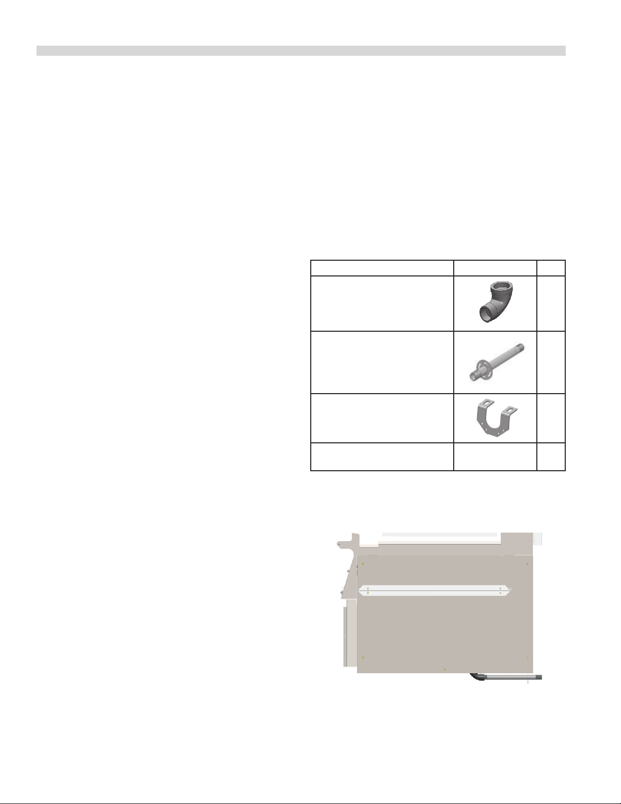
Accessory Kit – Main Gas Inlet:
(Accessory kit part numbers 4524785 or 4525509 and also
includes electrical supply lines, see next section).
Each griddle is supplied with an extended rear gas manifold
kit., with the following parts.
DESCRIPTION PART DRAWING QTY.
3/4”x 3/4” 90 Degree Elbow
Nipple Assembly
Manifold Support Bracket
8-32x0.375” PH PAN HD T/C
(self-tapping screws)
Installation of Kit:
1. Install the nipple assembly in the reduction elbow
(3/4” NPT) connected to the manifold. (Figure A)
1
1
1
4
2. The front casters on the appliance are equipped with
brakes to limit the movement of the appliance without
placing any strain on the connector or quick-disconnect
device or its associated piping.
3. Please be aware; required restraint is attached to a
bracket (which is located on the rear caster closest to the
gas connection), and if disconnection of the restraint
is necessary; be sure to reconnect the device after the
appliance has been returned to its original position.
Figure A
SSM09 (03/11/10)Page 8
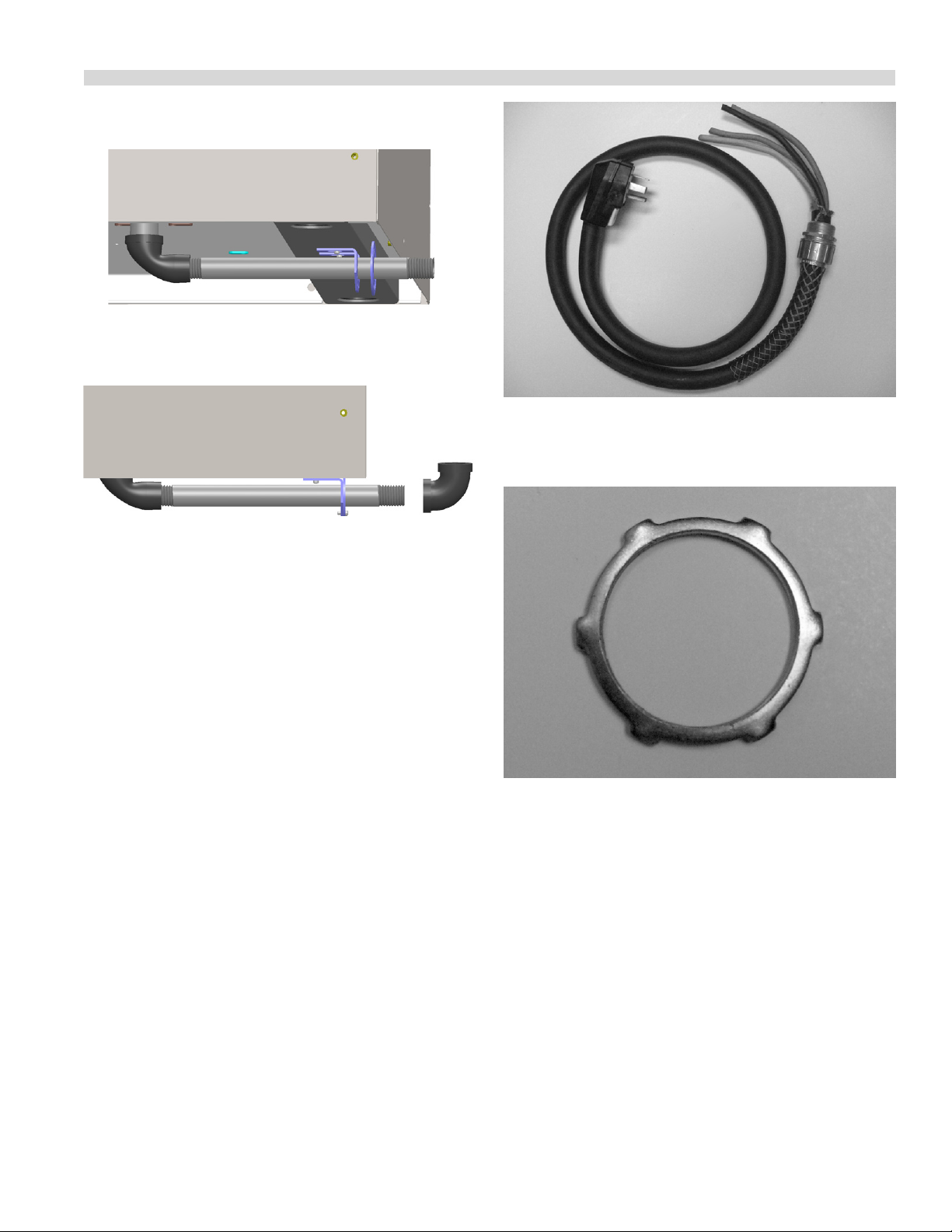
INSTALLATION continued
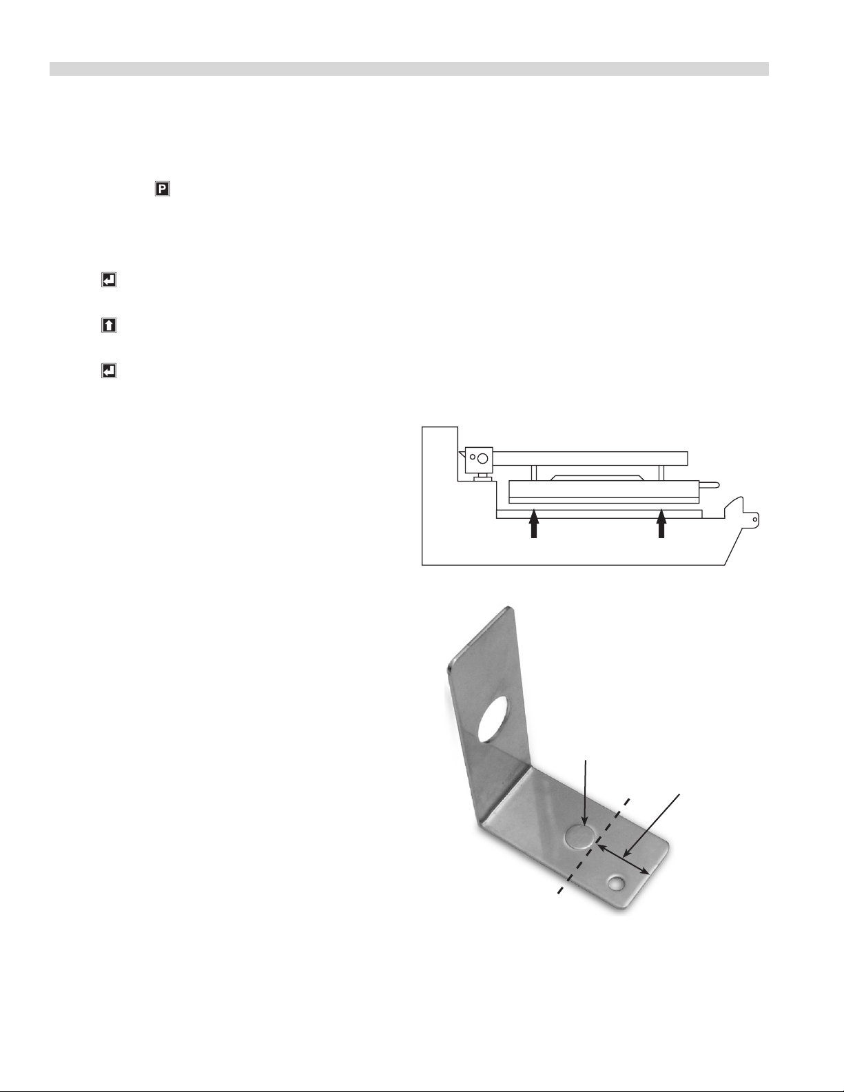
2. Install the manifold support bracket over the nipple and
leave the two screws loose. (Figure B)
Figure B
3. Adjust the manifold support bracket ush with the rear
gas support bracket. (Figure C)
Figure C
Photo D
3. Remove the locknut from at the end of the cord. Refer to
photo E.
4. Tighten the two loose screws of the manifold support
bracket onto the frame U-channel.
5. Lock the two brackets together using two screws.
(Figure C)
6. ¾” 90 degree elbow is supplied, to be installed if required.
Accessory Kit – Electrical Supply Lines:
The accessory kit also contains electric power cord and
plug and has a stain relief suited for each unit. Refer to Plug
Conguration in SPECIFICATIONS and Photo D
Installation of Cord And Plug With Strain Relief:
1. Remove the left grease bucket support attached by two
metal screws and the stainless steel left side body panel
attached by ve metal screws.
2. Remove the cord & plug and strain relief assembly from
the accessory kit. Refer to photo D.
Photo E
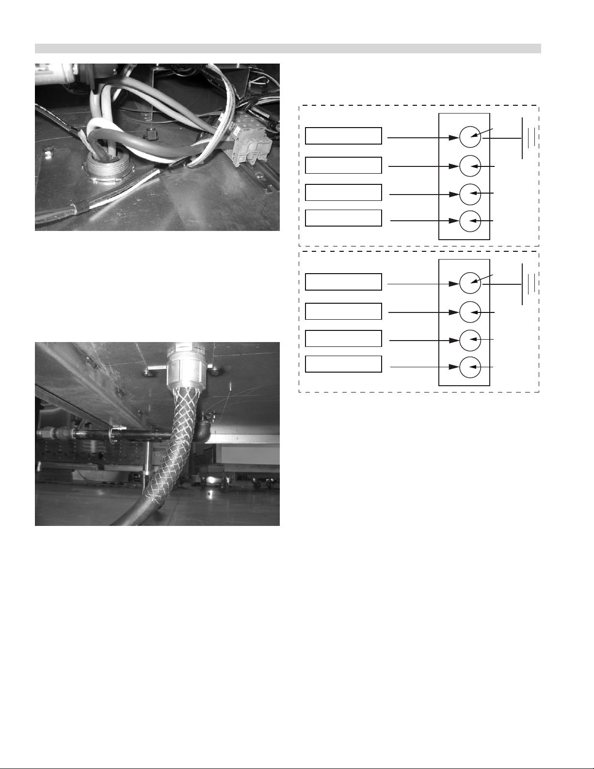
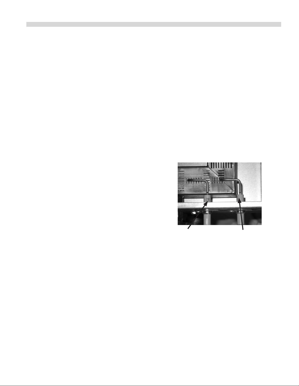
4. Insert loose wires and strain relief cord end through
the hole at the bottom of the unit. Refer to photo F and
secure with locknut. Refer to photo E.
SSM09 (03/11/10) Page 9
Wire leads from
Main Terminal
INSTALLATION continued
Photo F
5. Attached wire ends to terminal block as shown in next
section and referenced in wiring diagrams at back of this
manual.
6. Reinstall the side panel and grease bucket support with
metal screws. The external electrical connection should
appear as in photo G.
Cord and Plug
3-PHASE
Green-Ground
White - Z
Black - Y
Red - X
SINGLE PHASE
Green-Ground
Black - Z
White - Y
Red - X
Block of Grill
G
Z
Y
X
G
L1
N
L2
Photo G
Electrical Connection
Terminal Block Connection
All electrically operated appliances must be electrically
grounded in accordance with local codes; or in the absence
of local codes, with the latest edition of National Wiring
Regulations. A wiring diagram is located behind the rear
panel of the grill. For proper voltages, see rating plate in the
circuit breaker box, or on the right-rear frame upright.
Note: see diagram below for connections to terminal block.
Grease Bucket:
The griddle is supplied with two stainless steel side grease
buckets that must be installed before the unit is used. Each
bucket slides into position along stainless steel supports.
Ventilation and Clearance:
One of the most important considerations for ecient grill
operation is proper ventilation and air supply. Insure the
grill is installed so the products of combustion are removed
eciently and the ventilation system does not produce
drafts that interfere with proper burner operation.
Proper operation of exhaust fans (speed, rotation and
adjustment) is essential. In addition to the exhaust system
the make-up air system, (HVAC), for the kitchen is the
air supply for the combustion air for the burners. Proper
incoming air is essential for all gas operated equipment. Poor
incoming make-up will cause inecient burner operation,
delayed ignition and possible burner failure.
Any ventilation system will break down if improperly
maintained. The duct system, the hood, and the lters must
be cleaned on a regular basis and kept grease free.
SSM09 (03/11/10)Page 10
INSTALLATION continued
The room containing the grill is required to have a
permanent air vent. The minimum eective area of the vent
shall be 0.7 in.² per kW. Air vents shall be of such a size to
compensate for the eects of any extract fan in the premises.
Changing to a dierent type of gas
Changing from one gas type to another must only be
done by a Qualied Gas Engineer and according to local
regulations.
The gas valve, enrichment tube igniter and orice must be
changed to that supplied by the Authorized Service Agency
for the gas you are changing to. On completion of changing
these three components, you should test all joints for leaks,
verify that the manifold pressure is adjusted to the value
given in the specication pages in this manual, and repeat
the burner air adjustment procedure. This is to be found
on the following page in this manual. When the burner is
correctly adjusted, the alternate rating plate decal must
be placed over the existing rating plates to reect the new
category for which the grill is set.
To change from one gas type to another within the same
category (High to Low Caloric Value Natural Gas or vice
versa), change the orice to that supplied by the Authorized
Service Agency.
Note: the correct air fuel mixture and gas pressures must be
obtained before proceeding with igniter adjustment
1. Loosen the two 5\16” hex head #10 screws just outboard
of the igniter. This allows the igniter and its bracket
vertical movement.
2. With the Microamp meter in the ame sense line, and the
adjustment screws just loose enough to be able to move
the igniter assembly up and down, ignite the burner
and move the igniter up and down until the maximum
Microamp reading is achieved.
3. Tighten up the adjuster screws and the job is complete.
Igniter Inspection
The ignitor is next to the ame sensor in the burner
compartment. Normally, it should not require any
adjustment. If, however, the gap between the ignitor tip
and the burner is too great, or the ignitor seems to generate
a weak spark, replace the ignitor, and recheck the new
component for normal operation.
Burner Air Adjustment
1. The Xpress Grill gas model burner is a stainless steel
rectangular assembly that receives forced air from a fan
mounted below the burner. The fan air quality can be
slightly adjusted if the ame quality is poor to the point
that the ame sensor will be unreliable.
2. Loosen the lock nut holding the air adjustment in place.
Slowly turn the air adjustment out (counterclockwise).
The ame should be stable (no lifting) and be 1/8” to 1/4”
predominately blue.
Igniter Adjustment
The Igniter location is factory set and does not normally
require adjustment. Adjustment should only be conducted
if the Micro-Amp (µA) reading taken by placing a MicroAmp (µA) meter in line between the ignition module and
the ame sense wire reads below 0.22 Microamps (µA). The
normal reading is around 0.80 (µA) to 1.5 (µA). If the reading
is low, the igniter can be a moved up or down to achieve the
proper signal. The following is a description of the process.
IGNITOR
FLAME SENSOR
SSM09 (03/11/10) Page 11
BUTTON
BUTTON
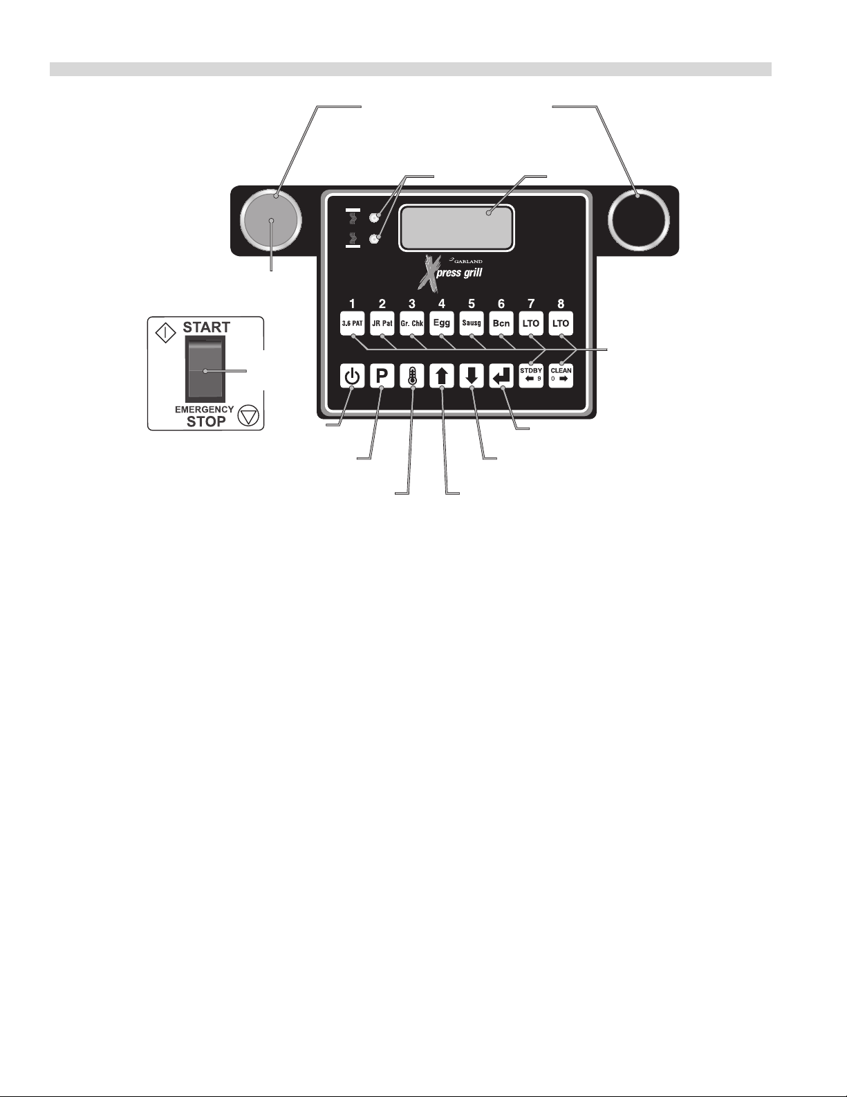
GRILL CONTROLS
CANCEL/
RAISE PLATEN
BUTTON
MASTER
POWER
SWITCH
POWER
BUTTON
PROGRAM
"START COOK TIME COUNTDOWN" (flat grill cooking)
BUTTON
TEMPERATURE
WHEN PUSHED SIMULTANEOUSLY:
OR "LOWER PLATEN" (two-sided cooking)
LED
INDICATORS
DOWN ARROW
BUTTON
UP ARROW
DISPLAY
ENTER
BUTTON
PRODUCT
BUTTONS
Master Power Switch:
Controls power to the grill and must be turned “ON” to start
operation. The controller display will be active when the
switch is “ON”.
LED Indicators:
There are two, (2), indicator lights, indicating the
temperature status of each control’s heat zones; one, (1), on
the upper platen, (top light), and one, (1), on the grill surface.
Each light can display three, (3), dierent colors, indicating
temperature status for the corresponding zone.
Red: The zone is too hot, (more than 79°F/45°C over the set
temperature), or heat zone failure.
Amber: The zone is calling for heat.
Green: The zone is at or above the set temperature.
Display:
The controller display will contain information relevant to
each operation in both cook and program modes.
Product Buttons (0-9):
Buttons 0-9 can be assigned to product items. Buttons 9 and
0 are used to move the cursor left or right when creating
or modifying product names in “PROD NAME LIB” program
mode.
Power Button:
After the main power switch is turned on, this button will put
the control into cook mode. If pressed again, the control will
go back to displaying “OFF.”
SSM09 (03/11/10)Page 12
GRILL CONTROLS continued
Program Button:
The primary function is to access Programming and
Calibration of the grill. Push and hold for ve (5) seconds.
Display will ask for the code. After entering code, ve
programming features will be accessible “MENU ITEMS,”
“SYSTEM INFO,” “SYSTEM SETUP,” “SERVICE MODE,” and
“PRODUCT NAME LIB.”
Temperature Button:
In the Cook mode, each time the button is pressed the
current temperature for one zone is displayed. The grill
temperature is displayed rst followed by the platen
temperature. After ve (5) seconds, the display will return to
the menu item selected.
Up/Down Arrow Buttons; 2 Functions:
1. In the cook mode, the Up/Down Arrow Buttons will cycle
through the dierent menu items.
2. In the program mode, the Up/Down Arrow Buttons will
change the value of the current setting.
Enter Button:
Function is to accept programming steps.
Cancel/Raise Platen Button, (Green):
During the cooking cycle, pressing this button will cancel the
cooking timer and return the grill to the “IDLE” mode. This
button will also bring the grill out of STANDBY.
Black Button:
When both Black and Green “CANCEL/RAISE” buttons are
pressed simultaneously, the upper platen will lower to the
griddle surface.
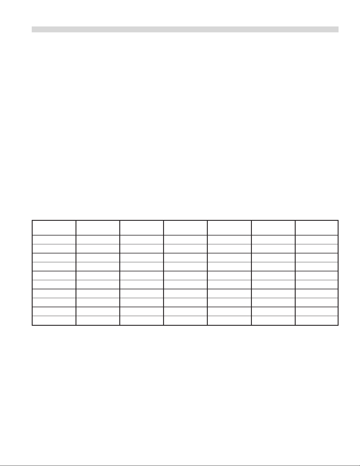
Main Pre-Programed Product Items
Abbrev Cook Time Upper Platen Upper Temp Grill Temp Gap
3-6 Pat 1:20 YES 425°F 350°F 0.320 1
JR Pat 1:20 YES 425°F 350°F 0.300 2
Gr. Chk. 2:00 YES 425°F 350°F 0.460 3
Sausg 1:45 YES 425°F 350°F 0.320 4
Egg :50 YES 425°F 350°F 0.310 5
Bcn 1:15 YES 425°F 350°F 0.100 6
LTO 1:20 YES 425°F 350°F 0.320 7
LTO 1:20 YES 425°F 350°F 0.320 8
STDBY N/A YES 425°F 350°F 0.250 9
CLEAN N/A YES 250°F 250°F 0.250 10
Key
Assingment
SSM09 (03/11/10) Page 13
PLATEN ZEROING
Turn Master power switch “ON”, wait for controllers to display
“OFF”.
Note: Release sheets should not be installed during this
procedure.
1. Press and hold for three, (3) seconds. “ENTER CODE” is
displayed.
2. Using the Product buttons, 0-9 enter the code, (1251).
“ENTER CODE **** ” is displayed.
3. Press to enter the Programming Mode.
“PROGRAMMING MODE MENU ITEMS” is displayed.
4. Press two, (2) times in succession to display
“PROGRAMMING MODE SYSTEM SETUP.”
5. Press six, (6) times. “PLATEN SET +/- XX” is displayed.
(XX=numbers that will vary from grill to grill.)
6. Allow time for grill to heat and turn ready. Press
both the Cancel (Green) and Standby (Black) buttons
simultaneously to lower the upper platen. Press the
Cancel (Green) button to raise the platen. Now, press
both the Cancel (Green) and (Black) Buttons to re-lower
the platen.
10. Move next to the left front adjuster and raise the platen
until the gapping tool ts snugly between the upper
platen and grill surface.
11. Next go to the left rear adjuster and raise the platen until
the gapping tool ts snugly between the upper platen
and grill surface.
12. Move next to the right front adjustment and raise the
platen until the gapping tool ts snugly between the
upper platen and grill surface.
13. Repeat steps 9-12 one or more times until gapping tool
ts snugly between the upper platen and grill surface at
all four adjustment points without further adjustment.
(See diagram below.)
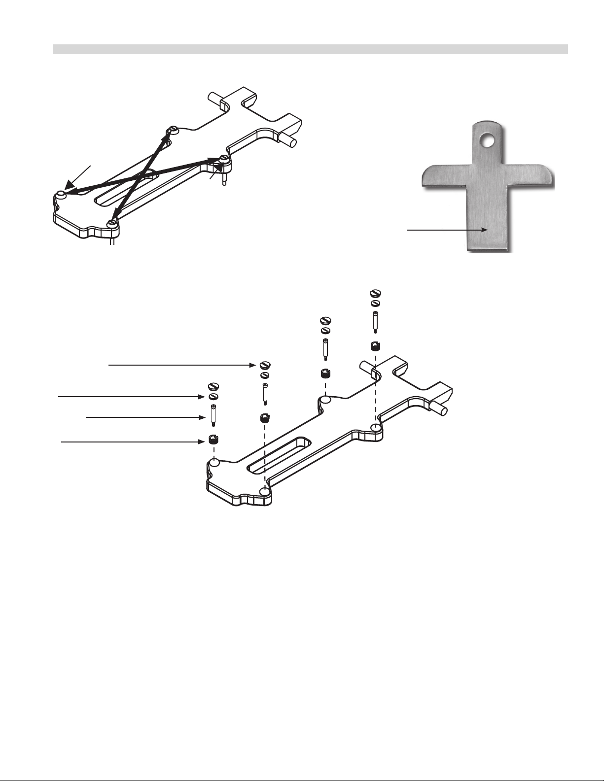
14. Replace the platen adjuster locking caps “hollow side
down” and tighten snugly. Replace platen adjuster caps.
15. Repeat steps 9-14 for each platen.
7. Remove platen adjuster caps from all four adjustment
points on each platen. Remove the four locking caps from
the adjustment points.
8. Using the adjusting tool lower platen until adjusting tool
touches the arm assembly.
9. With gapping tool, adjust right rear of platen until the
gapping tool ts snugly between the upper platen and
grill surface.
Insert gap tool directly below platen adjusters.
Platen Gapping Tool -1838701
“No-Go”
“Go”
SSM09 (03/11/10)Page 14
PLATEN ZEROING continued
Lower
Front
Left
Raise
Back
Right
Platen leveling should be done from one corner
to the opposite corner. The adjuster nuts should
be turned opposite of one another.
Platen Adjusting Tool - 4523323
Use this end to turn all slotted
adjuster caps and nuts
Platen Adjuster Cap - 1859102
Platen Adj Lock Nut - 1859103
Shoulder Bolt - 8005401
Platen Adjuster Nut - 1859101
SSM09 (03/11/10) Page 15
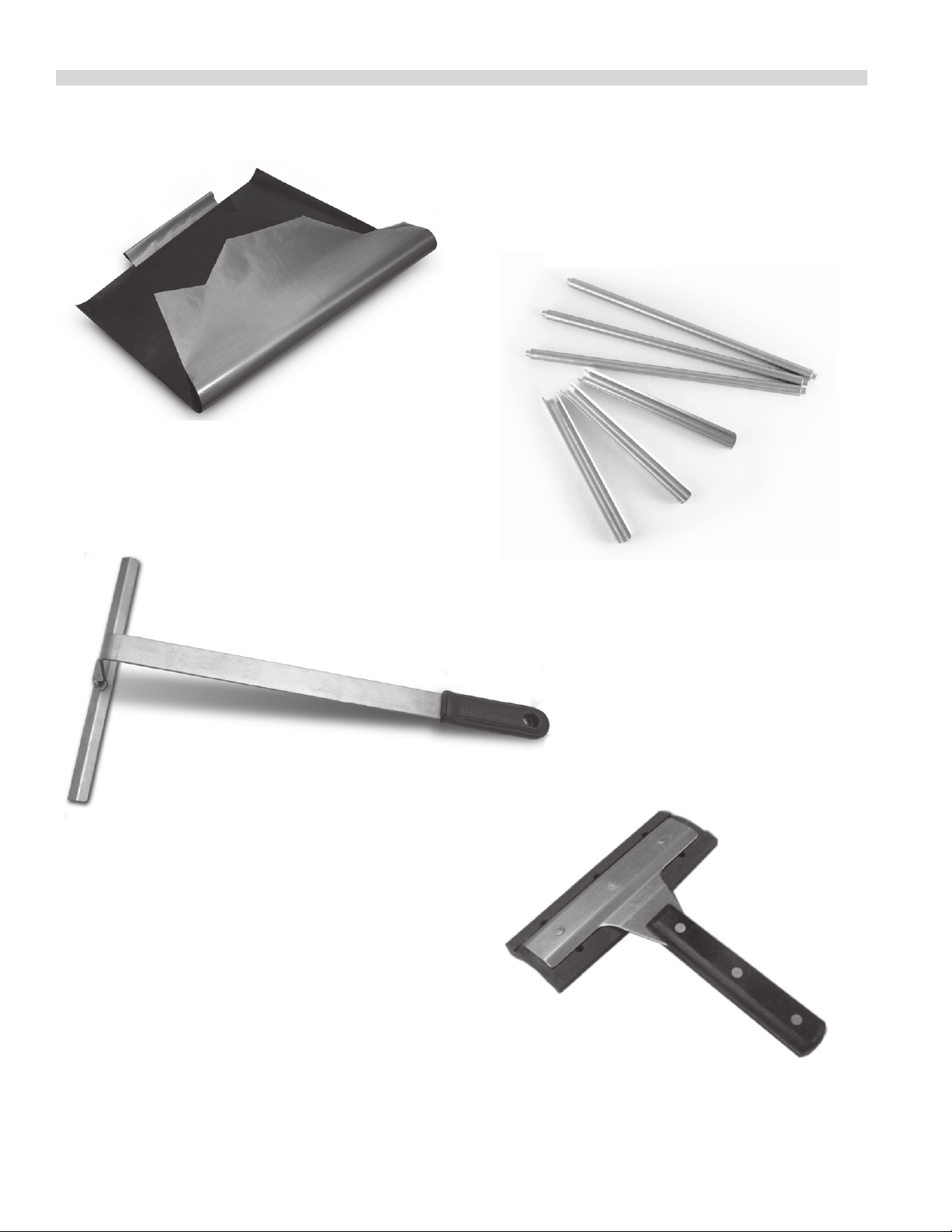
OPTIONAL ACCESSORIES
Teflon Release Material Sheet - 1799303
(one per platen)
Teflon Release Material Rod - 4517008
(one per platen; 3 shown)
Teflon Release Material Installation Tool - 4525560
Teflon Release Material Clip - 1851301
(one per platen; 3 shown)
Grill Squeegee - 1868201
SSM09 (03/11/10)Page 16
 Loading...