

Page 1
INSTALLATION AND
OPERATION MANUAL
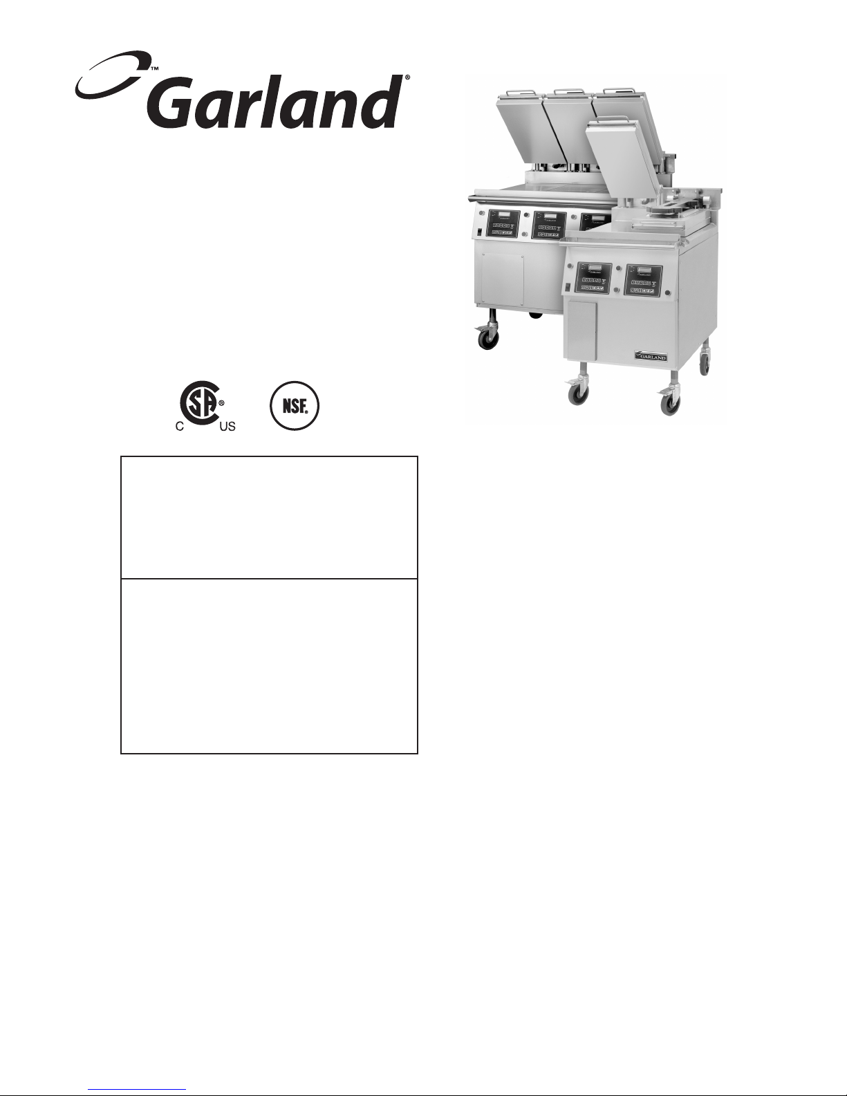
THE GARLAND
ELECTRIC XPRESS GRILL,
MODELS XE24, XE36
FOR YOUR SAFETY:
DO NOT STORE OR USE GASOLINE
OR OTHER FLAMMABLE VAPORS OR
LIQUIDS IN THE VICINITY OF
THIS OR ANY OTHER
APPLIANCE
PLEASE READ ALL SECTIONS OF THIS MANUAL
AND RETAIN FOR FUTURE REFERENCE.
THIS PRODUCT HAS BEEN CERTIFIED AS
COMMERCIAL COOKING EQUIPMENT AND
MUST BE INSTALLED BY PROFESSIONAL
PERSONNEL AS SPECIFIED.
WARNING:
IMPROPER INSTALLATION, ADJUSTMENT,
ALTERATION, SERVICE OR MAINTENANCE
CAN CAUSE PROPERTY DAMAGE, INJURY,
OR DEATH. READ THE INSTALLATION,
OPERATING AND MAINTENANCE
INSTRUCTIONS THOROUGHLY
BEFORE INSTALLING OR
SERVICING THIS EQUIPMENT
Users are cautioned that maintenance and repairs must be performed by a Garland authorized service agent
using genuine Garland replacement parts. Garland will have no obligation with respect to any product that has been
improperly installed, adjusted, operated or not maintained in accordance with national and local codes or installation
instructions provided with the product, or any product that has its serial number defaced, obliterated or removed,
or which has been modified or repaired using unauthorized parts or by unauthorized service agents.
For a list of authorized service agents, please refer to the Garland web site at http://www.garland-group.com.
The information contained herein, (including design and parts specifications), may be superseded and is subject
to change without notice.
GARLAND COMMERCIAL RANGES, LTD.
1177 Kamato Road, Mississauga, Ontario L4W 1X4
CANADA
Phone: 905-624-0260
Fax: 905-624-5669
INSTALLATION AND ELECTRICAL CONNECTION
MUST COMPLY WITH CURRENT CODES:
IN CANADA - THE CANADIAN ELECTRICAL
CODE PART 1 AND / OR LOCAL CODES.
IN USA – THE NATIONAL ELECTRICAL CODE
ANSI / NFPA – CURRENT EDITION.
ENSURE ELECTRICAL SUPPLY CONFORMS WITH
ELECTRICAL CHARACTERISTICS SHOWN ON
THE RATING PLATE.
Part # 4517125 Rev. 2 (01/09/12)
© 2005 Garland Commercial Industries, Inc.
Page 2
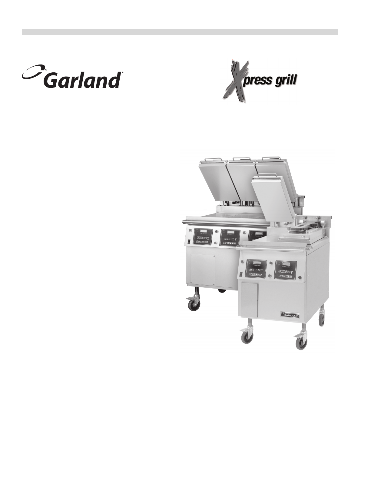
INTRODUCTION
The Garland Xpress Grill provides a method for ecient two-sided cooking, while accommodating a variety of products. The
unit will also serve as a at grill, and meets all standards for safety, eciency, and cleanliness.
Standard Features:
• Stainless steel front, top & sides
• 4.3kW input for each twelve-inch section of griddle
• 208V/220V/240V, three phase bottom heaters
• ¾" thick, Carbon steel griddle plate, machine ground,
highly polished
• Swivel casters complete with front brakes (4)
• Die cast aluminum electric top heating elements rated
208V/220V/240V
• Automatic lifting and lowering top heaters
• Towel bar with bun pan lip
• Stainless steel dual side grease collectors
• Separate programmable controller for each
twelve-inch section
• Multi-colored LED indicator lights to identify operational
mode
• One year limited parts and labor warranty
(USA & Canada)
Part # 4517125 Rev. 2 (01/09/12)Page 2
Page 3

TABLE OF CONTENTS
DIMENSIONS AND SPECIFICATIONS, MODEL XE24 . . . . 4
DIMENSIONS AND SPECIFICATIONS, MODEL XE36 . . . . 5
SAFETY PRECAUTIONS . . . . . . . . . . . . . . . . . . . . . . . . . . . . . 6
INSTALLATION . . . . . . . . . . . . . . . . . . . . . . . . . . . . . . . . . . . . . 7
Swivel Caster Installation. . . . . . . . . . . . . . . . . . . . . . . . . . . . . . . 7
Electrical Connections: . . . . . . . . . . . . . . . . . . . . . . . . . . . . . . . . . 7
National Codes Requirements . . . . . . . . . . . . . . . . . . . . . . . . . . 7
GRILL CONTROLS. . . . . . . . . . . . . . . . . . . . . . . . . . . . . . . . . . . 8
Master Power Switch: . . . . . . . . . . . . . . . . . . . . . . . . . . . . . . . . . . . . . 8
LED Indicators:. . . . . . . . . . . . . . . . . . . . . . . . . . . . . . . . . . . . . . . . . 8
Display: . . . . . . . . . . . . . . . . . . . . . . . . . . . . . . . . . . . . . . . . . . . . . . . 8
Product Buttons (1-8): . . . . . . . . . . . . . . . . . . . . . . . . . . . . . . . . . . 8
Power Button: . . . . . . . . . . . . . . . . . . . . . . . . . . . . . . . . . . . . . . . . . 8
Program Button: . . . . . . . . . . . . . . . . . . . . . . . . . . . . . . . . . . . . . . . 8
Temperature Button: . . . . . . . . . . . . . . . . . . . . . . . . . . . . . . . . . . . 9
Up/Down Arrow Buttons; 2 Functions: . . . . . . . . . . . . . . . . . 9
Enter Button: . . . . . . . . . . . . . . . . . . . . . . . . . . . . . . . . . . . . . . . . . . 9
Cancel/Raise Platen Button, (Green): . . . . . . . . . . . . . . . . . . . 9
Black Button: . . . . . . . . . . . . . . . . . . . . . . . . . . . . . . . . . . . . . . . . . . 9
OPERATION. . . . . . . . . . . . . . . . . . . . . . . . . . . . . . . . . . . . . . . 10
Installing Release Material: . . . . . . . . . . . . . . . . . . . . . . . . . . . .10
Lighting Instructions: . . . . . . . . . . . . . . . . . . . . . . . . . . . . . . . . .10
Simplied Cook Cycle Instructions: . . . . . . . . . . . . . . . . . . . .11
To Cook in Two-Sided Mode: . . . . . . . . . . . . . . . . . . . . . . . . . .11
To Cook in Flat Grill Mode:. . . . . . . . . . . . . . . . . . . . . . . . . . . . .12
Enter Standby Mode:. . . . . . . . . . . . . . . . . . . . . . . . . . . . . . . . . .12
Exit Standby Mode: . . . . . . . . . . . . . . . . . . . . . . . . . . . . . . . . . . .12
To Display the Current Temperatures: . . . . . . . . . . . . . . . . . .12
To View Settings for a Menu Item:. . . . . . . . . . . . . . . . . . . . . .12
To Clean the Grill: . . . . . . . . . . . . . . . . . . . . . . . . . . . . . . . . . . . . .12
PLATEN SET: . . . . . . . . . . . . . . . . . . . . . . . . . . . . . . . . . . . . . . . . . .13
EXTENDED TIME: . . . . . . . . . . . . . . . . . . . . . . . . . . . . . . . . . . . . . .13
INSTANT ON TIME: . . . . . . . . . . . . . . . . . . . . . . . . . . . . . . . . . . . .13
START DELAY: . . . . . . . . . . . . . . . . . . . . . . . . . . . . . . . . . . . . . . . . .13
CLEANING AND MAINTENANCE . . . . . . . . . . . . . . . . . . . . 13
Cleaning During Operation. . . . . . . . . . . . . . . . . . . . . . . . . . . .13
Daily Cleaning . . . . . . . . . . . . . . . . . . . . . . . . . . . . . . . . . . . . . . . .13
PLATTEN ZEROING . . . . . . . . . . . . . . . . . . . . . . . . . . . . . . . . 15
ACCESSORIES . . . . . . . . . . . . . . . . . . . . . . . . . . . . . . . . . . . . . 16
PROGRAMMING. . . . . . . . . . . . . . . . . . . . . . . . . . . . . . . . . . . 19
Programming Modes/Menu Sequence: . . . . . . . . . . . . . . . .19
Menu Items...
To Change the Cook Time of a Product: . . . . . . . . . . . . . . . .21
To Turn Platen, (2-Sided), Cooking On/O: . . . . . . . . . . . . . 21
To Change Upper Platen Set Temperature: . . . . . . . . . . . . .21
To Change Grill Set Temperature: . . . . . . . . . . . . . . . . . . . . . .21
To Change Product Gap Setting:. . . . . . . . . . . . . . . . . . . . . . .21
To Change Product Button, “Key” Assignment . . . . . . . . . .21
To Change a Product Name: . . . . . . . . . . . . . . . . . . . . . . . . . . .22
System Info...
To View Recovery Time - Upper Platen:. . . . . . . . . . . . . . . . .22
To View Recovery Time - Grill:. . . . . . . . . . . . . . . . . . . . . . . . . .22
To View the Garland Part Number: . . . . . . . . . . . . . . . . . . . . .22
To View the Flash Number: . . . . . . . . . . . . . . . . . . . . . . . . . . . .23
To View the Software Number:. . . . . . . . . . . . . . . . . . . . . . . . .23
To View the Download Number: . . . . . . . . . . . . . . . . . . . . . . .23
System Setup
To Change temperature Units, (°F or °C): . . . . . . . . . . . . . . .23
To Change Gap Setting Display Units:. . . . . . . . . . . . . . . . . .23
To Change the Alarm Volume: . . . . . . . . . . . . . . . . . . . . . . . . .24
To Change the Key Chirp:. . . . . . . . . . . . . . . . . . . . . . . . . . . . . .24
To Change Upper Set Temperature . . . . . . . . . . . . . . . . . . . .24
To Change Grill Set Temperature. . . . . . . . . . . . . . . . . . . . . . .24
To Change Probe Calibration - Upper:. . . . . . . . . . . . . . . . . .24
To Change Probe Calibration - Grill: . . . . . . . . . . . . . . . . . . . .25
To Change Platen Gap Set: . . . . . . . . . . . . . . . . . . . . . . . . . . . .25
To Change Instant-On Time:. . . . . . . . . . . . . . . . . . . . . . . . . . .25
To Change Control Type: . . . . . . . . . . . . . . . . . . . . . . . . . . . . . .25
To Turn Extended Time On/O: . . . . . . . . . . . . . . . . . . . . . . . .26
To Change the Grill Function:. . . . . . . . . . . . . . . . . . . . . . . . . .26
To Change the Start Delay: . . . . . . . . . . . . . . . . . . . . . . . . . . . .26
To Change the Alarm Mode: . . . . . . . . . . . . . . . . . . . . . . . . . . .26
To Turn Clean Mode On/O: . . . . . . . . . . . . . . . . . . . . . . . . . . .27
To Add a Product Name in Library: . . . . . . . . . . . . . . . . . . . . .27
To Modify a Product Name in Library: . . . . . . . . . . . . . . . . . .27
Service Mode
To Change SCK Address:. . . . . . . . . . . . . . . . . . . . . . . . . . . . . . .27
To Perform Limit Switch Test: . . . . . . . . . . . . . . . . . . . . . . . . . .28
CALIBRATION . . . . . . . . . . . . . . . . . . . . . . . . . . . . . . . . . . . . . 28
Bi-Weekly Calibration:. . . . . . . . . . . . . . . . . . . . . . . . . . . . . . . . .28
ERROR LOGIC & TROUBLESHOOTING. . . . . . . . . . . . . . . . 30
Probe Error . . . . . . . . . . . . . . . . . . . . . . . . . . . . . . . . . . . . . . . . . . .30
Heating Error . . . . . . . . . . . . . . . . . . . . . . . . . . . . . . . . . . . . . . . . .30
Platen Down Error . . . . . . . . . . . . . . . . . . . . . . . . . . . . . . . . . . . .31
Platen Up Error. . . . . . . . . . . . . . . . . . . . . . . . . . . . . . . . . . . . . . . .31
Gas Ignition Error . . . . . . . . . . . . . . . . . . . . . . . . . . . . . . . . . . . . .31
COMM Error . . . . . . . . . . . . . . . . . . . . . . . . . . . . . . . . . . . . . . . . . .31
Motor Overcurrent Error. . . . . . . . . . . . . . . . . . . . . . . . . . . . . . .31
Motor Error . . . . . . . . . . . . . . . . . . . . . . . . . . . . . . . . . . . . . . . . . . .31
Motor Error2. . . . . . . . . . . . . . . . . . . . . . . . . . . . . . . . . . . . . . . . . .32
Lower Switch Error . . . . . . . . . . . . . . . . . . . . . . . . . . . . . . . . . . . .32
Upper Switch Error. . . . . . . . . . . . . . . . . . . . . . . . . . . . . . . . . . . .32
WIRING DIAGRAM. . . . . . . . . . . . . . . . . . . . . . . . . . . . . . . . . 33
Part # 4517125 Rev. 2 (01/09/12) Page 3
Page 4
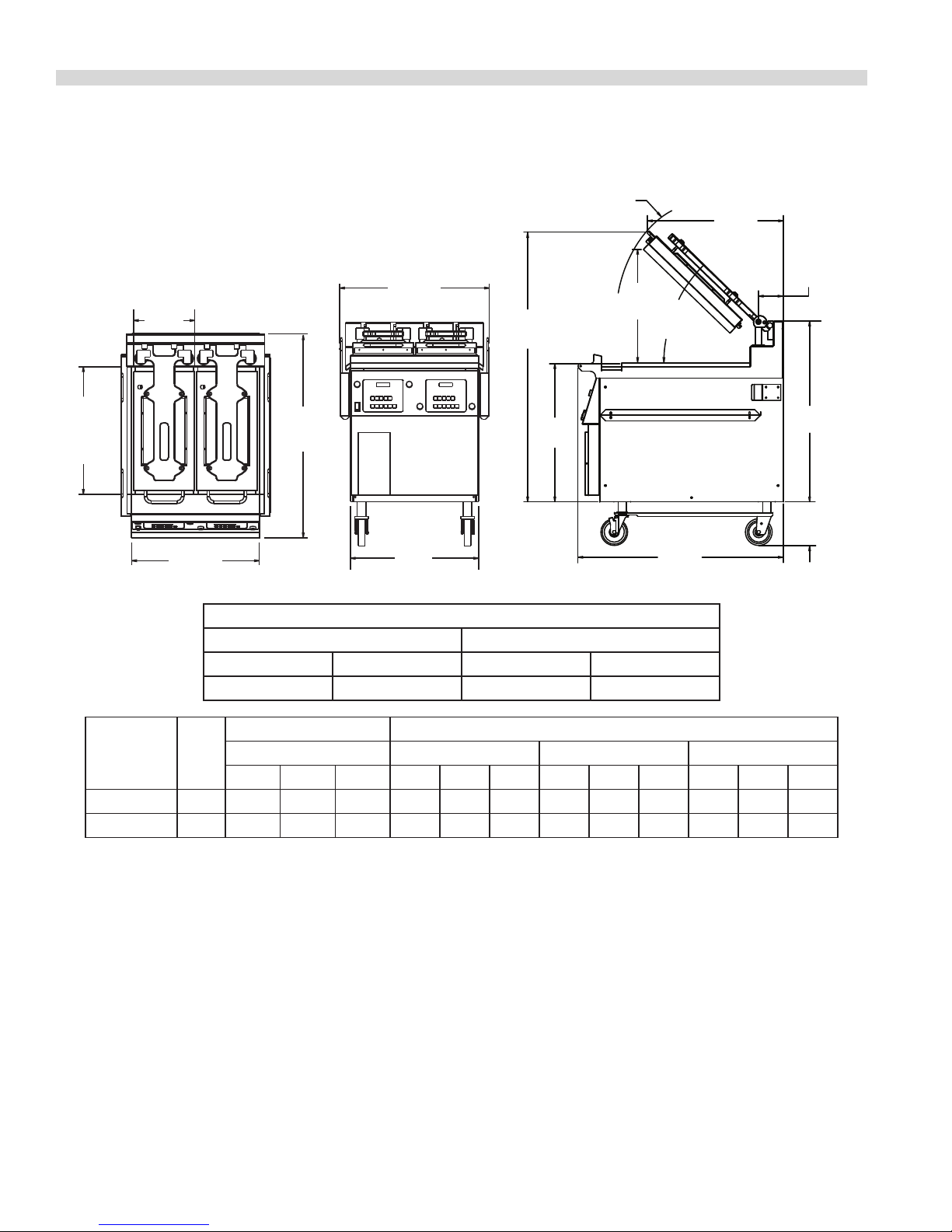
DIMENSIONS AND SPECIFICATIONS, MODEL XE24
26-23/32"
[678mm]
FROM PLATEN
ARM PIVOT
11-1/2"
[292mm]
TOP
HEATER
(2 PLACES)
TOP VIEW
28-3/16"
[716mm]
50-1/2"
[1282mm]
AVERAGE
23"
[584mm]
MAX
44.03°
AVERAGE
[48° MAX]
25-1/2"
[646mm]
AVERAGE
4-41/64"
[118mm]
24"
[610mm]
GRILL
PLATE
DEPTH
24"
[610mm]
GRILL PLATE WIDTH
38-1/2"
[978mm]
25-7/8"
[656mm]
FRONT VIEW RIGHT SIDE VIEW
38-25/64"
24-1/8"
[614mm]
[975mm]
Clearances
Entry Installation
Crated Uncrated Sides Rear
47-1/2" (1207mm) 32" (813mm) 6" (152mm) 3" (76mm)
Total
Model
Load
Loading kW Per Phase Nominal Amps Per Line
kW
208/220/240V 3PH 208V 3-Phase Delta 220V 3-Phase Delta 240V 3-Phase Delta
X-Y X-Z Y-Z X Y Z X Y Z X Y Z
XE24 17.30 5.53 6.01 5.53 48.04 46.04 48.04 45.42 43.53 45.42 41.64 39.90 41.64
XE24-1 L/R 12.98 4.33 5.58 4.33 37.09 36.05 37.09 35.07 34.08 35.07 32.15 31.24 32.15
33-25/32"
[858mm]
7" [178mm] MIN
11" [279mm] MAX
Part # 4517125 Rev. 2 (01/09/12)Page 4
Page 5
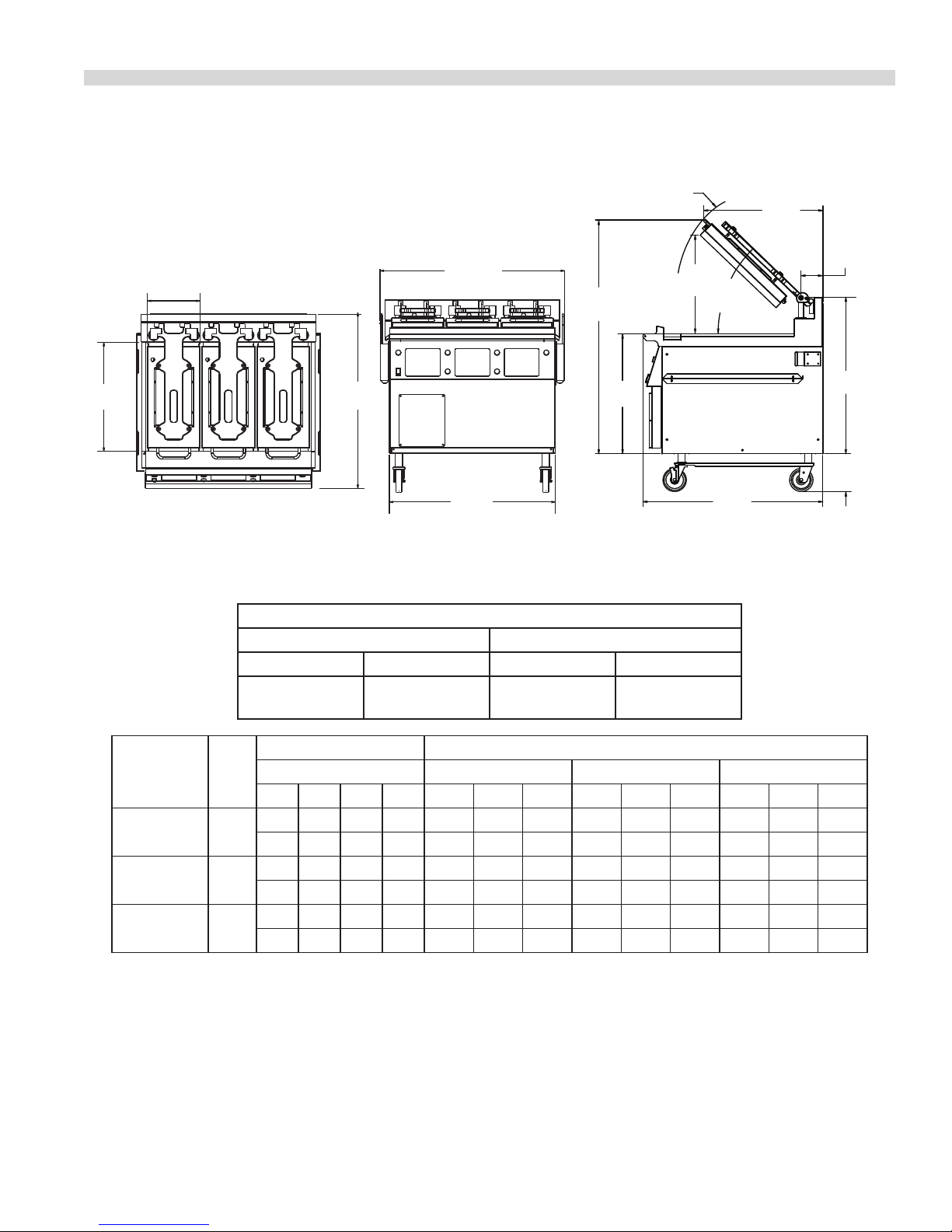
DIMENSIONS AND SPECIFICATIONS, MODEL XE36
24"
[610mm]
11-1/2"
[292mm]
TOP HEATER
(3 PLACES)
TOP VIEW
38-1/2"
[978mm]
GRILL PLATE 24"x 36"
[610mm x 914mm]
40-3/16"
[1021mm]
36-5/32"
[918mm]
FRONT VIEW
25-1/2"
[646mm]
AVERAGE
23"
[584mm]
MAX
44.03°
AVERAGE
[48° MAX]
33-25/32"
[858mm]
RIGHT SIDE VIEW
7" [178mm] MIN
11" [279mm] MAX
26-23/32"
[678mm]
FROM PLATEN
ARM PIVOT
50-1/2"
[1282mm]
AVERAGE
4-41/64"
[118mm]
25-7/8"
[656mm]
38-25/64"
[975mm]
Total
Model
kW
Load
XE36 25.60
XE36-2 L/R 21.60
XE36-1 L/C/R 17.6
* In North America XE36 model grills with top heaters require two (2) electric supplies
Clearances
Entry Installation
Crated Uncrated Sides Rear
47-1/2"
(1207mm)
40-3/4"
(1035mm)
6" (152mm) 3" (76mm)
Loading kW Per Phase Nominal Amps Per Line
208/220/240V 3-Phase 208V 3-Phase Delta 220V 3-Phase Delta 240V 3-Phase Delta
* X-Y X-Z Y-Z X Y Z X Y Z X Y Z
TB1 5.53 6.01 5.53 48.04 46.04 48.04 45.42 43.53 45.42 41.64 39.90 41.64
TB2 2.78 2.78 2.78 23.14 23.14 23.14 21.88 21.88 21.88 20.06 20.06 20.06
TB1 4.19 4.67 4.19 36.88 34.88 36.88 34.88 32.98 34.88 31.96 30.23 31.96
TB2 2.78 2.78 2.78 23.14 23.14 23.14 21.88 21.88 21.88 20.06 20.06 20.06
TB1 2.90 3.50 2.90 26.60 24.10 26.60 25.19 22.83 25.19 23.09 20.06 23.09
TB2 2.78 2.78 2.78 23.14 23.14 23.14 21.88 21.88 21.88 20.06 20.06 20.06
TB1 = Terminal Block 1, TB2 = Terminal Block 2
Part # 4517125 Rev. 2 (01/09/12) Page 5
Page 6

SAFETY PRECAUTIONS
Always follow these safety precautions when operating the
Xpress Grill.
• THIS GRILL MUST be operated by persons who have
been given adequate training.
• THIS EQUIPMENT MUST ONLY BE OPERATED UNDER AN
APPROVED HOOD SYSTEM.
• DO NOT operate the grill without reading this operation
manual.
• DO NOT operate the Xpress grill unless all service and
access panels are in place and fastened properly.
The Garland Xpress Grill is a semi-automatic cooking
appliance. The upper platen is lowered automatically,
following the manual, two-handed initiation of the cooking
cycle, and the upper platen is raised automatically upon
completion of the cooking cycle.
When two sided cooking, the area between the upper platen
and the griddle plate should be regarded as a “danger zone.”
During two sided cooking the operator must not be within
this danger zone. When used as a at grill, then this area is no
longer a danger zone, the platens do not move.
For whatever reason, be it cleaning, maintenance, or normal
operation, any exposed person must use extreme caution if
within this danger zone.
In two side cooking the upper platen remains in the lowered
position by nature of its own weight. It is not locked down. It
can be raised by lifting up on the handle on the front of the
platen.
The Xpress Grill may during its operation emit airborne noise
equivalent to a continuous A weighted sound pressure level
of 73dB(A).
WARNING: To avoid serious personal injury:
• DO NOT attempt to repair or replace any part of the
Xpress Grill unless all main power supplies to the grill
have been disconnected.
• USE EXTREME CAUTION in setting up, operating and
cleaning the Xpress Grill to avoid coming in contact
with hot grill surfaces or hot grease. Suitable protective
clothing should be worn to prevent the risk of burns.
• DO NOT clean this appliance with a water jet.
• DO NOT apply ICE or COLD WATER to a HOT grill surface.
• NOTE all warning labels and markings axed to the grill.
WARNING: After turning the master power switch to the
START position, the grill will go through initialization. If
the upper platens are in the lowered position they will
return to their raised upper position. This movement takes
approximately 8 seconds.
Part # 4517125 Rev. 2 (01/09/12)Page 6
Page 7

INSTALLATION
IMPORTANT: Rating plate for this appliance is located on
the right side panel.
This equipment must be installed by a competent factory
trained, certied, licensed and / or authorized service or
installation person.
Swivel Caster Installation
Prior to installation, the four casters, supplied loose with the
grill, must be securely located on the underside of the base.
The casters tted with a brake must be located at the front of
the grill.
1. Carefully remove the top and side packaging leaving the
grill on shipping pallet.
DO NOT REMOVE THE TIES SECURING THE PLATEN ARMS
TO THE GRILL TOWEL BAR.
2. Raise the grill vertically o the pallet to a comfortable
working height and install the casters. DO NOT TIP THE
GRILL ON ITS BACK OR SIDE. If a truck lift is used, be
careful when inserting the lifting arms under the grill as
the gas inlet elbow is protruding in the center of the base.
WARNING - GRILL WEIGHT IS APPROXIMATELY 800 LBS –
USE CAUTION
The grill is to be located directly under ventilation system.
Once installed in the grill station underneath the ventilation
system, the platens, in their highest position, must not
interfere with the lower lip of the ventilation system hood.
The raised position of each platen is adjusted by raising
or lowering the upper of the two microswitches, (limit
switches), in the rear of the grill. The lower microswitch
position must not be adjusted.
Grill plate must be level front to back, side to side and
diagonally. This leveling must be done with the unit under
the hood and in it’s normal operational position to prevent
warping of the grill plate.
NOTE: Fuses are installed to prevent damage in the event of
failure of the upper microswitch.
Electrical Connections:
WARNING: This appliance must be properly grounded.
All electrically operated appliances must be electrically
grounded in accordance with local codes; or in the absence
of local codes, with the latest edition of National Wiring
Regulations. A wiring diagram is located on the rear panel of
the grill. See rating plate in rear of grill, or lower front panel
for proper voltages.
3. Install the casters as shown below. The two casters with
brakes go on the front, and the two without on the rear.
WITH
BRAKE
NOTE: CASTERS MUST BE THREADED INTO GRILL BASE
LEAVING APPROXIMATELY ONE INCH OF EXPOSED
THREAD. THIS IS THE STARTING POINT FOR LEVELLING THE
GRILL AFTER IT IS IN POSITION.
WITHOUT
BRAKE
This appliance should be connected to a potential
equalization system. A labeled equipotential bonding point
is tted to the rear of the grill.
It is recommended that this grill be connected to a residual
current,, (earth leakage),, device with a tripping current not
exceeding 30mA. The leakage current of this grill will not
exceed 5mA.
CAUTION: Prior to installation, check the electrical supply
to ensure input voltage and phase match the equipment
voltage rating and phase. See data plate located rear left side
of grill and lower front panel.
National Codes Requirements:
In Canada, electrical connection must comply with
applicable sections of the Canadian Electrical Code, C22.1
- 1990, latest edition, “Safety Standard for Installation,
Part 1” and C22.2- No. O-M 1982 latest edition , “General
Requirements, Part 2”.
Part # 4517125 Rev. 2 (01/09/12) Page 7
Page 8

BUTTON
BUTTON
GRILL CONTROLS
CANCEL/
RAISE PLATEN
BUTTON
MASTER
POWER
SWITCH
POWER
BUTTON
PROGRAM
"START COOK TIME COUNTDOWN" (flat grill cooking)
BUTTON
TEMPERATURE
WHEN PUSHED SIMULTANEOUSLY:
OR "LOWER PLATEN" (two-sided cooking)
LED
INDICATORS
UP ARROW
16-CHARACTER
2-LINE DISPLAY
ENTER
BUTTON
DOWN ARROW
BUTTON
PRODUCT
BUTTONS
Master Power Switch:
Controls power to the grill and must be turned “ON” to start
operation. The controller display will be active when the
switch is “ON”.
LED Indicators:
There are two, (2), indicator lights, indicating the
temperature status of each control’s heat zones; one, (1), on
the upper platen, (top light), and one, (1), on the grill surface.
Each light can display three, (3), dierent colors, indicating
temperature status for the corresponding zone.
Red: The zone is too hot, (more than 79°F/45°C over the set
temperature), or heat zone failure.
Amber: The zone is calling for heat.
Green: The zone is at or above the set temperature.
Display:
The controller display will contain information relevant to
each operation in both cook and program modes.
Product Buttons (1-8):
Buttons 8 and 0 are used for standby and clean. They also
can be used in programming to the cursor left or right when
creating or modifying product names in “PROD NAME LIB”
program mode.
Power Button:
After the main power switch is turned on, this button will put
the control into cook mode. If pressed again, the control will
go back to displaying “OFF.”
Program Button:
The primary function is to access Programming and
Calibration of the grill. Push and hold for ve (5) seconds.
Display will ask for the code. After entering code, ve
programming features will be accessible “MENU ITEMS,”
“SYSTEM INFO,” “SYSTEM SETUP,” “SERVICE MODE,” and
“PRODUCT NAME LIB.”
Part # 4517125 Rev. 2 (01/09/12)Page 8
Page 9

GRILL CONTROLS continued
Temperature Button:
In the Cook mode, each time the button is pressed the
current temperature for one zone is displayed. The grill
temperature is displayed rst followed by the platen
temperature. After ve (5) seconds, the display will return
to the menu item selected. Pressing and holding the
temperature button for 5 seconds will display both the grill
and platen temperatures. To exit press the temperature
button.
Up/Down Arrow Buttons; 2 Functions:
1. In the cook mode, the Up/Down Arrow Buttons will cycle
through the dierent menu items.
2. In the program mode, the Up/Down Arrow Buttons will
change the value of the current setting.
Enter Button:
Function is to accept programming steps.
Cancel/Raise Platen Button, (Green):
During the cooking cycle, pressing this button will cancel the
cooking timer and return the grill to the “IDLE” mode. This
button will also bring the grill out of STANDBY.
Black Button:
When both Black and Green “CANCEL/RAISE” buttons are
pressed simultaneously, the upper platen will lower to the
griddle surface.
Part # 4517125 Rev. 2 (01/09/12) Page 9
Page 10
OPERATION
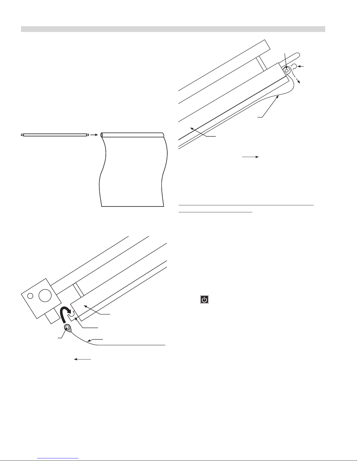
Installing Release Material:
A release material sheet must be replaced when:
• Product sticks to release material.
• Carbon build-up ruins taste or appearance.
• Tearing occurs in the sheet’s cooking area.
• Release material coating is worn o sheet.
Slide release material rod through hemmed end of the
release material sheet.
Hook release material rod on brackets located at the rear of
the upper plate
Holding the bottom of the release material sheet in place,
gently pull the sheet toward the front of the platen.
RELEASE
MATERIAL
BAR
RELEASE
MATERIAL
LOCKING
CLIP (1)
RELEASE
MATERIAL
UPPER PLATEN (side view)
FRONT OF GRILL
NOTE: Make sure release material ts smoothly over upper
platen. Installing release material sheets too tight may cause
premature failure of the sheet.
Release sheets are reversible and should be ipped over
and reattached on a daily basis. For instructions on cleaning
release sheets, see Step 17., under Daily Cleaning in Cleaning
and Maintenance section
Lighting Instructions:
UPPER PLATEN (side view)
RELEASE MATERIAL HOOK
RELEASE
MATERIAL ROD
RELEASE MATERIAL SHEET
REAR OF GRILL
Thread the front edge of the release material sheet behind
the release material bar on the front of the platen, then
around the top and down over the front of the bar as shown.
Place locking clips over release material sheet and press into
place over release material bar.
1. Ensure that the exible gas hose is connected to the grill
and the power cord is plugged into the receptacles.
2. Turn the main power switch ON and allow the controls
to go through the power-up self-check. Once the control
panel displays the word “OFF” the unit is ready to begin
the heating process.
3. Press . The control will automatically initiate the
heating cycle. The burner will ignite and heat until the
temperature specied by the menu item has been
obtained.
If ignition of the burner does not occur on the rst trial, the
bottom indicator light will ash amber. If the burner(s) do
not light within four trials for ignition, the control will display
a ashing warning, “IGNITION ERROR.” The ashing amber
light will turn to solid red and an audible alarm will sound. If
this occurs, turn the main power switch o, wait 5 minutes,
and then repeat steps 2 and 3.
Check alignment and tightness of release material against
upper platen.
Part # 4517125 Rev. 2 (01/09/12)Page 10
Page 11
- - - - - - -
*** *
START
STOP
EMERGENCY
- - - - - - -
*** *
START
STOP
EMERGENCY
Clam Grill Operating Instructions
2
- - - - - - -
*** *
START
STOP
EMERGENCY
- - - - - - -
*** *
START
STOP
EMERGENCY
- - - - - - -
*** *
START
STOP
EMERGENCY
Press button to turn on main
power to grill.
Press button to turn zone power on.
Clam Grill Operating Instructions
2
3.6 PATT Y
*** *
START
STOP
EMERGENCY
3.6 PATT Y
*** *
START
STOP
EMERGENCY
4
- - - - - - -
*** *
START
STOP
EMERGENCY
Press button to turn zone power on.
3.6 PATT Y
*** *
START
STOP
EMERGENCY
OPERATION continued
- - - - - - -
*** *
START
STOP
EMERGENCY
Press both green and black buttons
to lower clam and begin cook ing
product.
Press button to turn zone power on.
Clam Grill Operating Instructions
2
3.6 PATT Y
*** *
START
STOP
EMERGENCY
4
- - - - - - -
*** *
START
STOP
EMERGENCY
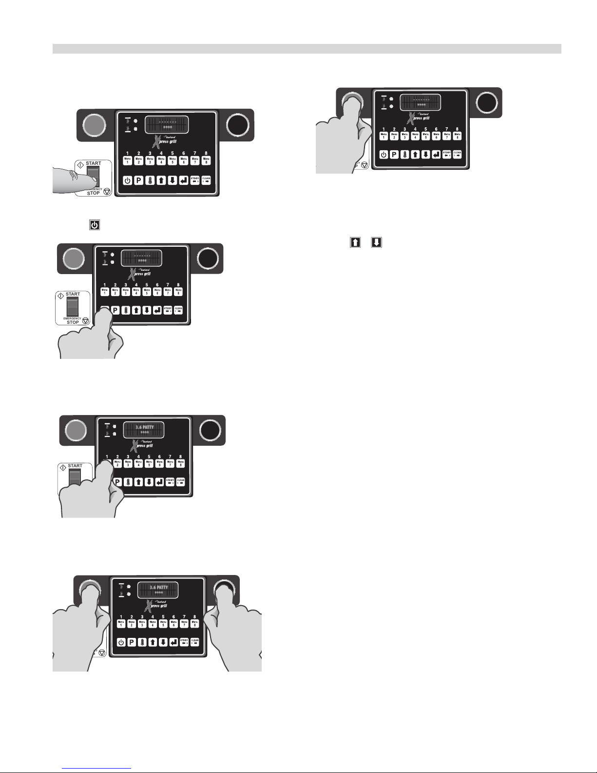
Simplied Cook Cycle Instructions:
1. Press button to turn on mainpower to grill.
2. Press to turn zone power on.
3. Load product on grill surface and select the
corresponding product key.
5. Press green button to cancel any time during cook cycle.
To Cook in Two-Sided Mode:
1. To start a cook cycle select a product recipe by using the
product keys (1 through 9) or by using the UP/DOWN
keys or to select a product recipe.
The display alternately blinks the recipe and the word
SELECTED 2 times then the recipe displays continuously.
2. The controller regulates the platen and grill temperatures
to the set temperatures of the product selected and
reads “TOO COOL” or “TOO HOT” with “MENU ITEM”, until
the grill attains the set temperature range for the item.
NOTE: If the display reads either “TOO COOL” or “TOO HOT”
the upper platen will not lower and initiate a cooking
sequence.
3 After loading the product onto the grill, press the green
CANCEL/RAISE PLATEN BUTTON and BLACK button
simultaneously. A cook cycle starts and the upper platen
lowers if the product selected is clamshell recipe.
4. Press both green and black buttons to lower clam and
begin cooking product.
Part # 4517125 Rev. 2 (01/09/12) Page 11
4 To cancel a cook cycle at anytime press the green
CANCEL/RAISE PLATEN BUTTON and the upper platen
will rise if the product recipe selected is clamshell recipe.
5. During a cook cycle, the display shows the product recipe
name in the rst line and the remaining cook time count
down in the second line.
6 When the cook timer reaches one, (1), second remaining
a pre-time-out alarm sounds alerting the operator.
7 When the cooking time has been completed the platen
raises automatically. On the controller the “PRODUCT
NAME” and the word “REMOVE” will be displayed and an
audible alert will sound.
8. Pressing the green CANCEL/RAISE PLATEN BUTTON stops
the audible alert and the unit will revert back to IDLE
mode.
Page 12

OPERATION continued
To Cook in Flat Grill Mode:
1. To start a cook cycle select a product recipe by using the
product keys (1 through 9) or by using the UP/DOWN
keys or to select a product recipe.
The display alternately blinks the recipe and the word
SELECTED 2 times then the recipe will be displayed
continuously.
2. The controller regulates the grill temperature to the set
temperature of the product selected and reads “TOO
COOL” or “TOO HOT” with “MENU ITEM”, until the grill
attains the set temperature range for the item.
NOTE: If the display reads either “TOO COOL” or “TOO HOT” it
will not initiate a cooking sequence.
3 After loading the product onto the grill, press the green
CANCEL/RAISE PLATEN BUTTON and BLACK button
simultaneously. That will start a cook cycle if the product
selected is clamshell recipe.
4 To cancel a cook cycle at anytime the press the green
CANCEL/RAISE PLATEN BUTTON .
Enter Standby Mode:
Stand by mode is used during slow periods to conserve
energy with out a complete shut down of the unit. When
cooking temperatures are again required, pre-heat cook
temperature/time is reduced. Stand by mode temperatures
can be adjusted, see the PROGRAMING section.
1. Select Standby Mode by pressing or until
“STANDBY” is displayed.
2. Press the GREEN (‘CANCEL/RAISE’) and the BLACK buttons
at the same time. As soon as the upper platen moves
down, the display will read “STANDBY MODE.” (Note: The
rst time Standby Mode is entered, the display prompts
the operator to press ENTER after pressing the GREEN
and BLACK buttons.)
Exit Standby Mode:
1. Press the GREEN (‘CANCEL/RAISE’) button. The upper
platen will raise and the display will read “CANCEL” with
an audible alarm.
To Display the Current Temperatures:
5. During a cook cycle, the display shows the product recipe
name in the rst line and the remaining cook time count
down in the second line.
6. The display shows the “SEAR” or “FLIP” alarm message
with ashing in the second line if the current cooking
product is at recipe and the sear time or ip time is not
zero.
7. A cook alarm sounds with a repeating beep pattern.
Pressing the black RAISE button acknowledges the “SEAR”
or “FLIP” alarm message if the alarm eld in system setup
is set to MANUAL.
8. The “SEAR” or “FLIP” alarm message stops after 5 seconds
if the alarm eld in system setup is set to AUTO.
9. When a cook is complete, the display shows the product
recipe name in the rst line and a ashing “REMOVE”
message in the second line. A repeating beeping alarm
also sounds.
10. Pressing the black RAISE button cancels the cook done
alarm.
11. The unit revertes back to IDLE mode.
1. Press the button and repeat for each zone to be
displayed...
1st press - LOWER GRILL ZONE
2nd press - UPPER PLATEN
3rd Pressing and holding the button for 5 seconds
will display both the grill and platen temperatures (preset
and actual). Press again ) to exit.
NOTE: The temperatures may be displayed at any time,
including during a cooking cycle.
To View Settings for a Menu Item:
1. Enter Programming; Menu Items, (see Programming)
2. Press to enter “PROGRAMMING MODE MENU ITEMS”
3. Use and to choose the desired Menu Item.
4. Press to scroll through settings for the chosen item.
To Clean the Grill:
1. To start a CLEAN MODE select the clean mode recipe by
pressing product key 10 or by using the UP/DOWN keys
or to select the clean mode recipe.
2. The controller regulates the platen and grill temperatures
to the set temperatures of the clean mode recipe. The
display shows the message “CLEAN MODE” in the rst line
and the actual grill temperature in the second line.
Part # 4517125 Rev. 2 (01/09/12)Page 12
Page 13

OPERATION continued
3. Press the ENTER key to initiate the clean mode.
4. The display SHOWS the message “READY TO CLEAN” with
ashing in the second line when the actual temperature
is reached (or greater than the set temperatures of clean
mode recipe (default 220°F or 250° for both the platen
and grill)). A 5 second repeating beep pattern is sounded.
5. Press the ENTER key again, the heater’s control for the
platen and grill are turned o and the display shows the
message “CLEANING” with ashing in the second line.
6. Press the ENTER key again to exit the CLEAN MODE. The
display shows the message “STANDBY” in the rst line.
The control transitions to “STANDBY MODE” and preheats
to idle condition.
PLATEN SET:
This function allows the platen to be moved up or down
once it is parallel to the grill surface. Values range from –160
to +160.
EXTENDED TIME:
This option will add 6, 4 and 2 seconds to the time of the next
three cooks respectively if the grill has had no activity for
5 minutes. Provided the temperature is not 25°F above set
temperature for either the grill or the platen.
INSTANT ON TIME:
This can be set in the range of 00:00 to 00:40. Instant on will
turn on the heat zone(s) as soon as a cook cycle starts.
START DELAY:
This number is how long the operator must hold the GREEN
(‘CANCEL/RAISE’) and BLACK buttons to start a cooking cycle
for 2-sided recipes only. There will be one beep when the
cook is started and another beep when the START DELAY
time is reached. If the GREEN (‘CANCEL/RAISE’) and BLACK
buttons are released before that time the cook will be
canceled. If Yes is toggled press enter to allow the user to
pick from 1 to 5 seconds in 0.5 second increments using
and .
CLEANING AND MAINTENANCE
Cleaning During Operation:
1. After each product load is removed, Use a grill scraper to
scrape grease on lower grill plate from front to back only.
Do not scrape left to right across the lower grill plate with
the grill scraper.
2. Use a grill squeegee to clean release material sheet on
upper platen in a downward motion. Do not press hard
against the release material sheet to prevent scratching
or tearing.
Daily Cleaning:
Warning: The upper platen surface and edges are very hot! To prevent burn injuries, use extreme caution when wiping
down release sheets and platen edges.
3. Push the grease to the rear of the grill, or pull it to the
front trough. Then, squeegee the grease into the buckets
on either side. Do not use the scraper for this step.
4. Use a clean, damp cloth to clean back splash and
bullnose areas as needed during operation.
Note: To increase life of release material sheets, wipe them
down with a folded clean, damp cloth at least four times
during each hour of operation.
High-Temperature
Grill Cleaner
Grill Cleaning Pad & Handle Grill Scraper
Part # 4517125 Rev. 2 (01/09/12) Page 13
Heat-Resistant Gloves Clean, Sanitizer-Soaked
Grill Cloths
Grill Squeegee
Page 14
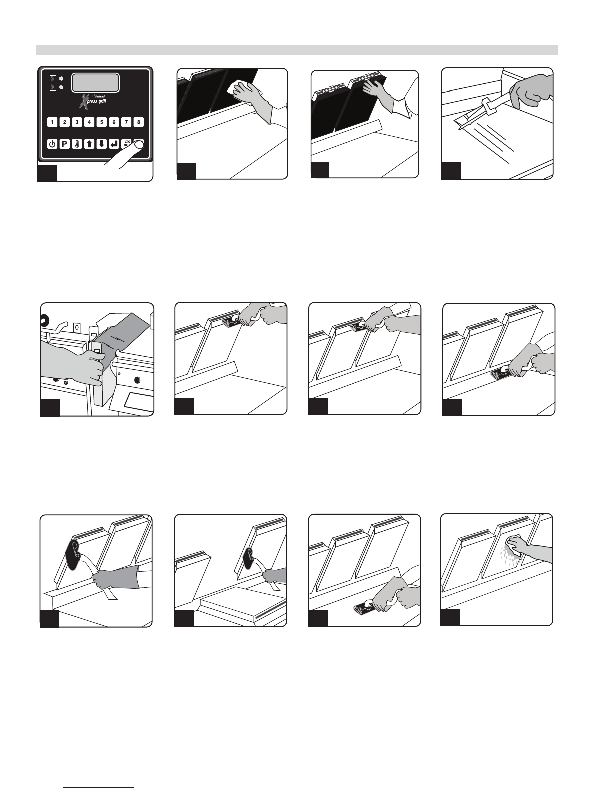
CLEANING AND MAINTENANCE continued
01
01
• Select Clean Mode
When Clean Mode has
been reached, the LED
indicators will turn GREEN.
05
• Remove the grease trough
from each side. Empty and
replace.
02
• Wipe the Release
Material sheets with a
clean,sanitizer-soaked
grill cloth.
06
• Apply the grill cleaner
to front side of platens
starting from right platen
to left platen.
• DO NOT SCRUB.
03
• Remove the locking clips,
bars, and release sheets.
Wash, rinse, and set aside
to dry.
• Set release sheets aside
on a at surface.
07
• Apply the grill cleaner to
platen surfaces starting
from right platen to left
platen.
• DO NOT SCRUB
04
• Scrape the lower grill
surface with the scraper.
• Use the grill squeegee to
push residual grease into
trough.
• Wash and rinse the
squeegee and scraper.
08
• Apply the grill cleaner to
back side of platens from
right platen to left platen.
• DO NOT SCRUB
09
• Apply the grill cleaner to
outer edges of right and
left platens.
• DO NOT SCRUB
• Press green & black
buttons to lower the
center platen.
10
• Apply grill cleaner to
inner edges of the right
and left platens, and
the edges of the center
platen.
• DO NOT SCRUB
• Press green button to
raise center platen..
11
• Apply grill cleaner to
bottom grill surface.
• Spread the cleaner over
the entire lower grill
surface from front to back
using even strokes.
• DO NOT SCRUB
12
• Rinse platen surfaces with
a clean, sanitizer-soaked
grill cloth, starting from
right to left platens.
• Press green & black
buttons to lower the
center platen.
Part # 4517125 Rev. 2 (01/09/12)Page 14
Page 15
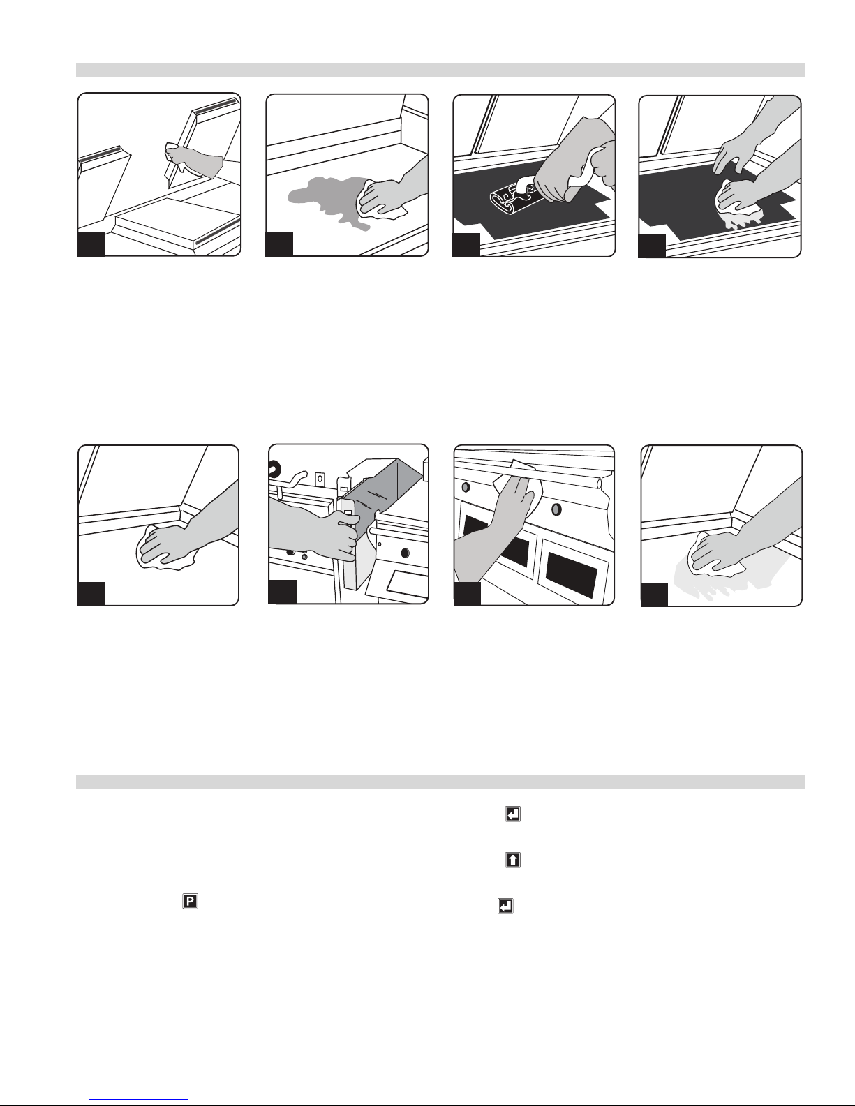
CLEANING AND MAINTENANCE continued
14
15
17
19
13
• Rinse the edges of all three
platens.
• Press green button to raise
center platen.
• Wipe lower grill with a
clean,sanitizer-soaked
grill cloth. Repeat until no
visible soil remains.
• Pour a small amount of
lukewarm water on a
clean, sanitizer-soaked
grill cloth over the
bottom grill surface and
wipe o residue.
18
• Empty, wash, rinse,
and replace the grease
troughs.
• Place upper platen
release material sheets
at on the lower grill
surface.
• Gently clean both sides
of the release material
sheets with the grill
cleaning pad
• Wipe remaining grill
surfaces with a clean,
sanitizer-soaked grill
cloth.
16
• Rinse both sides of
the release material
sheets with a clean,
sanitizersoaked grill cloth.
• Reinstall the release
material sheets. Secure in
place with bars and clips
20
• Apply a thin coat of fresh
shortening to the lower
grill surface only..
PLATEN ZEROING
Turn Master power switch “ON”, wait for controllers to display
“OFF”.
Note: Release sheets should not be installed during this
procedure.
1. Press and hold for three, (3) seconds. “ENTER CODE” is
displayed.
2. Using the Product buttons, 0-9 enter the code, (1251).
“ENTER CODE **** ” is displayed.
Part # 4517125 Rev. 2 (01/09/12) Page 15
3. Press to enter the Programming Mode.
“PROGRAMMING MODE MENU ITEMS” is displayed.
4. Press two, (2) times in succession to display
“PROGRAMMING MODE SYSTEM SETUP.”
5. Press eight, (8) times. “PLATEN SET +/- XX” is displayed.
(XX=numbers that will vary from grill to grill.)
6. Allow time for grill to heat and turn ready. Press
both the Cancel (Green) and Standby (Black) buttons
simultaneously to lower the upper platen. Press the
Page 16
PLATEN ZEROING
Cancel (Green) button to raise the platen. Now, press both
the Cancel (Green) and (Black) Buttons to re-lower the
platen.
7. Remove platen adjuster caps from all four adjustment
points on each platen. Remove the four locking caps from
the adjustment points.
8. Using the adjusting tool lower platen until adjusting tool
touches the arm assembly.
9. With gapping tool, adjust right rear of platen until the
gapping tool ts snugly between the upper platen and
grill surface.
10. Move next to the left front adjuster and raise the platen
until the gapping tool ts snugly between the upper
platen and grill surface.
ACCESSORIES
11. Next go to the left rear adjuster and raise the platen until
the gapping tool ts snugly between the upper platen
and grill surface.
12. Move next to the right front adjustment and raise the
platen until the gapping tool ts snugly between the
upper platen and grill surface.
13. Repeat steps 9-12 one or more times until gapping tool
ts snugly between the upper platen and grill surface at
all four adjustment points without further adjustment.
(See diagram below.)
14. Replace the platen adjuster locking caps “hollow side
down” and tighten snugly. Replace platen adjuster caps.
15. Repeat steps 9-14 for each platen.
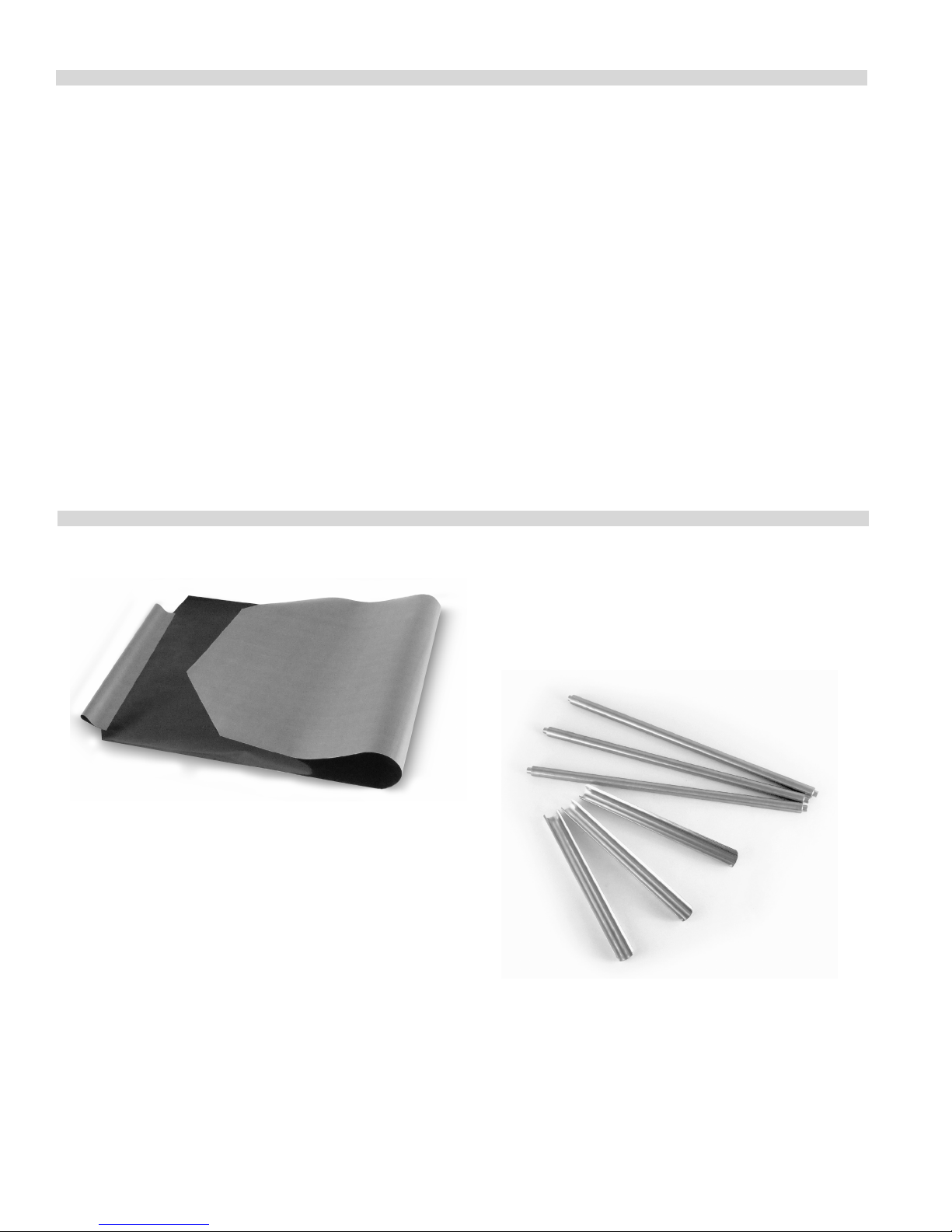
Teflon Release Material Sheet - 1799303
(one per platen)
Teflon Release Material Rod - 4517008
(one per platen; 3 shown)
Teflon Release Material Clip - 1851301
(one per platen; 3 shown)
Part # 4517125 Rev. 2 (01/09/12)Page 16
Page 17
ACCESSORIES
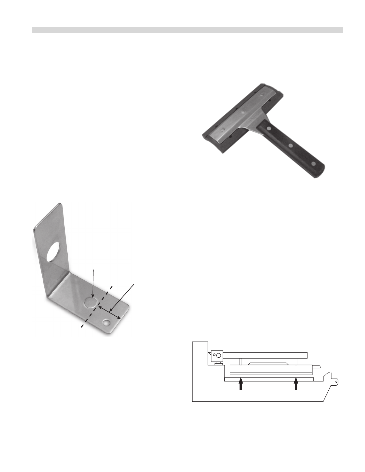
Grill Squeegee - 1868201
Platen Gapping Tool -1838701
“No-Go”
“Go”
Part # 4517125 Rev. 2 (01/09/12) Page 17
Insert gap tool directly below platen adjusters.
Page 18
PLATEN ZEROING continued
Lower
Front
Left
Raise
Back
Right
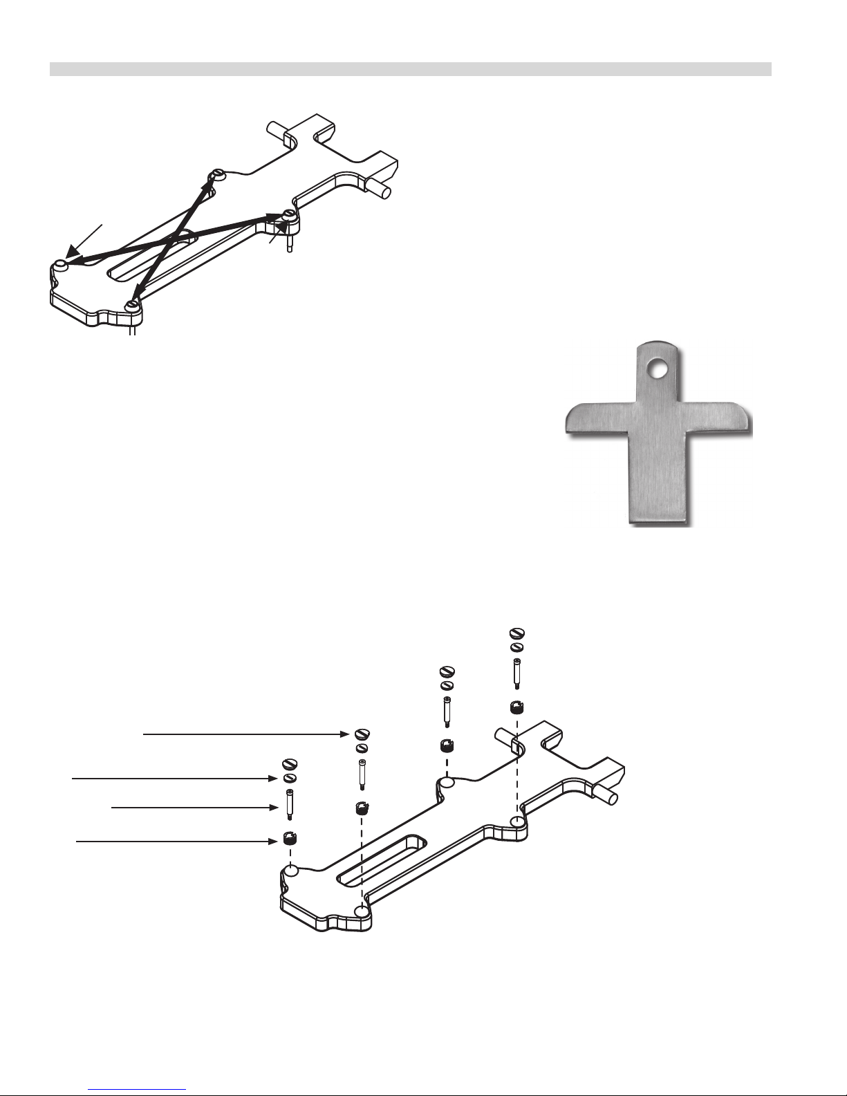
Platen leveling should be done from one corner
to the opposite corner. The adjuster nuts should
be turned opposite of one another.
Platen Adjusting Tool - 4523323
Platen Adjuster Cap - 1859102
Platen Adj Lock Nut - 1859103
Shoulder Bolt - 4527290
Platen Adjuster Nut - 1859101
Use this end to turn all slotted
adjuster caps and nuts
Part # 4517125 Rev. 2 (01/09/12)Page 18
Page 19
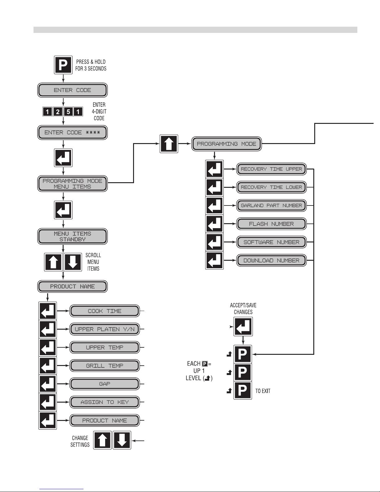
PROGRAMMING continued
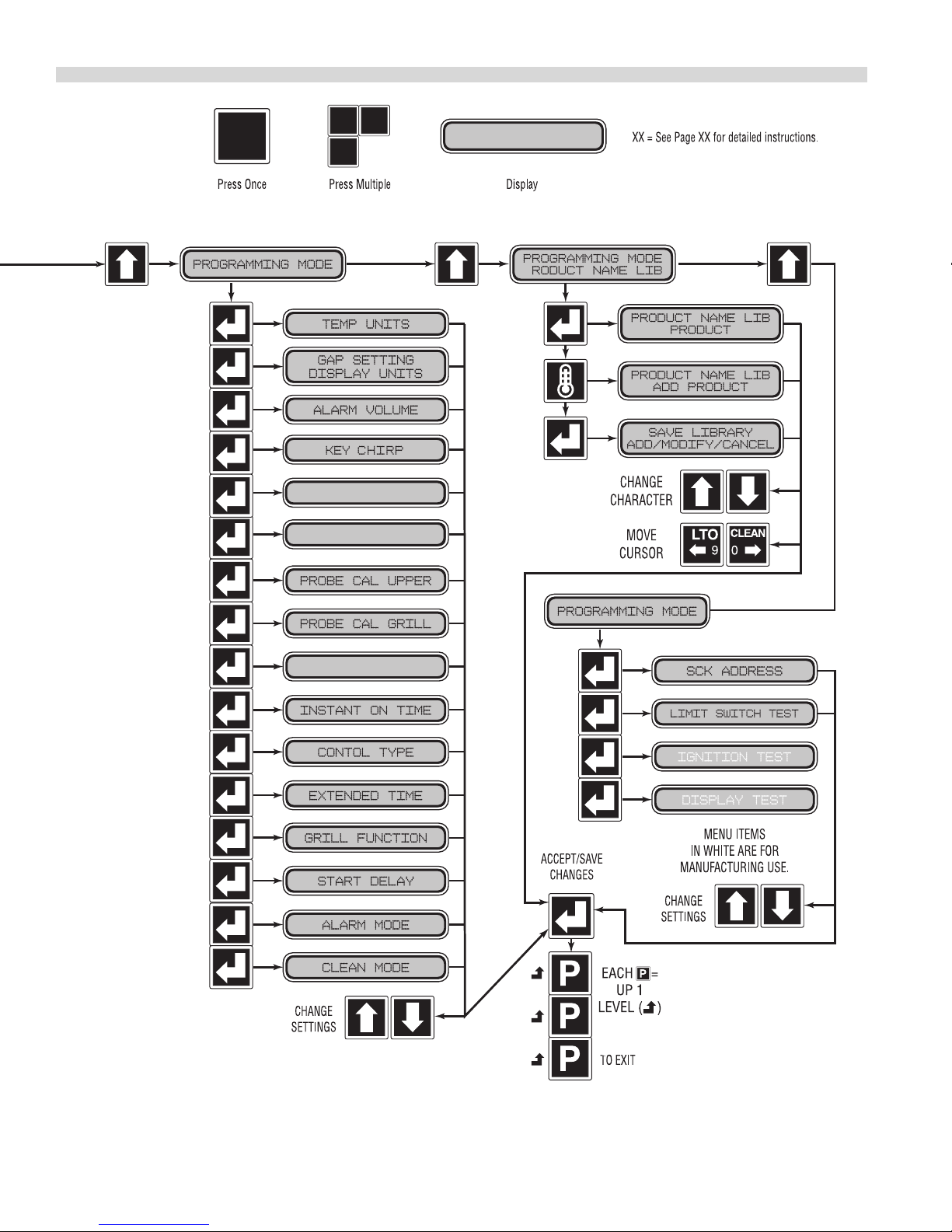
Programming Modes/Menu Sequence:
System Information
22
22
22
21
21
21
21
21
21
23
23
23
Part # 4517125 Rev. 2 (01/09/12) Page 19
22
Page 20
PROGRAMMING continued
System Set-up
UPPER SET TEMP
GRILL SET TEMP
PLATEN GAP SET
23
23
24
24
24
24
24
25
25
25
25
27
27
27
Service Mode
27
28
26
26
26
26
27
Part # 4517125 Rev. 2 (01/09/12)Page 20
Page 21

PROGRAMMING continued
Menu Items...
To Change the Cook Time of a Product:
1. Press and hold for three, (3) seconds. “ENTER CODE” is
displayed.
2. Using the Product buttons, 0-9 enter the code, (1251).
“ENTER CODE **** ” is displayed.
3. Press to enter Programming Mode. “PROGRAMMING
MODE MENU ITEMS” is displayed.
4. Press
Use and to choose the desired Menu Item.
5.
6. Press to display “(MENU ITEM) COOK TIME XX:XX”
7. Use and to adjust the cook time.
8. Press to save the changes.
9. Press twice to exit.
To Turn Platen, (2-Sided), Cooking On/O:
1. Press and hold for three, (3) seconds. “ENTER CODE” is
displayed.
2. Using the Product buttons, 0-9 enter the code, (1251).
“ENTER CODE **** ” is displayed.
3. Press to enter the Programming Mode.
“PROGRAMMING MODE MENU ITEMS” is displayed.
. “MENU ITEMS STANDBY” is displayed.
5. Use and to choose the desired Menu Item.
6 Press three, (3) times to display “(MENU ITEM) UPPER
TEMP XXX” displayed in °F or °C.
7. Use and to change the set temperature to the
desired value.
8. Press to save the changes.
9. Press twice to exit.
To Change Grill Set Temperature:
1. Press and hold for three, (3) seconds. “ENTER CODE” is
displayed.
2. Using the Product buttons, 0-9 enter the code, (1251).
“ENTER CODE **** ” is displayed.
3. Press to enter the Programming Mode.
“PROGRAMMING MODE MENU ITEMS” is displayed.
4.
Press . “MENU ITEMS STANADBY” or” MENU ASSIGNED
TO BUTTON 1” is displayed.
Use and to choose the desired Menu Item.
5.
6. Press four, (4) times to display “(MENU ITEM) GRILL
TEMP XXX” displayed in °F or °C.
7. Use and to change the set temperature to the
desired value.
8. Press to save the changes.
4.
Press . “MENU ITEMS STANADBY” or” MENU ASSIGNED
TO BUTTON 1” is displayed.
Use and to choose the desired Menu Item.
5.
6. Press twice to display “(MENU ITEM) UPPER PLATEN
YES/NO “.
7. Use and to turn upper platen on or o.
8. Press to save the changes.
9. Press twice to exit.
To Change Upper Platen Set Temperature:
1. Press and hold for three, (3) seconds. “ENTER CODE” is
displayed.
2. Using the Product buttons, 0-9 enter the code, (1251).
“ENTER CODE **** ” is displayed.
3. Press to enter the Programming Mode.
“PROGRAMMING MODE MENU ITEMS” is displayed.
4.
Press . “MENU ITEMS STANADBY” or” MENU ASSIGNED
TO BUTTON 1” is displayed.
9. Press twice to exit.
To Change Product Gap Setting:
1. Press and hold for three, (3) seconds. “ENTER CODE” is
displayed.
2. Using the Product buttons, 0-9 enter the code, (1251).
“ENTER CODE **** ” is displayed.
3. Press to enter the Programming Mode.
“PROGRAMMING MODE MENU ITEMS” is displayed.
4.
Press . “MENU ITEMS STANADBY” or” MENU ASSIGNED
TO BUTTON 1” is displayed.
Use and to choose the desired Menu Item.
5.
6. Press ve, (5) times to display “GAP XXX” displayed in
inches or mm.
7. Use and to change the gap setting to the desired
value.
8. Press to save the changes.
9. Press twice to exit.
Part # 4517125 Rev. 2 (01/09/12) Page 21
Page 22

PROGRAMMING continued
To Change Product Button, “Key” Assignment
1. Press and hold for three, (3) seconds. “ENTER CODE” is
displayed.
2. Using the Product buttons, 0-9 enter the code, (1251).
“ENTER CODE **** ” is displayed.
3. Press to enter the Programming Mode.
“PROGRAMMING MODE MENU ITEMS” is displayed.
4. Press
button 1 is displayed.
Use and to select any unused item from the Menu
5.
Item.
6. Press six, (6) to display “ASSIGN TO KEY (1-8 or NONE)”
- Make sure you have assigned desired values to time gap
and temperatures”.
NOTE: If time is left with zero value, the key assignment will
not go into eect.(you will hear double beep when choosing
key in cooking mode)
7. Use and to change the key, (Product Button),
assignment, and replace any previous assignments to
that key.
8. Press to save the changes.
9. Press twice to exit.
. “MENU ITEMS STANDBY” or menu assigned to
To Change a Product Name:
1. Press and hold for three, (3) seconds. “ENTER CODE” is
displayed.
2. Using the Product buttons, 0-9 enter the code, (1251).
“ENTER CODE **** ” is displayed.
3. Press to enter the Programming Mode.
“PROGRAMMING MODE MENU ITEMS” is displayed.
displayed.
2. Using the Product buttons, 0-9 enter the code, (1251).
“ENTER CODE **** ” is displayed.
3. Press to enter the Programming Mode.
“PROGRAMMING MODE MENU ITEMS” is displayed.
4. Press one, (1) time to display “PROGRAMMING MODE
SYSTEM INFO.”
5. Press to view the upper recovery time. “RECOVERY
UPPER XXXX” is displayed.
6. Press to return to “PROGRAMMING MODE SYSTEM
INFO”.
7. Press to exit.
To View Recovery Time - Grill:
1. Press and hold for three, (3) seconds. “ENTER CODE” is
displayed.
2. Using the Product buttons, 0-9 enter the code, (1251).
“ENTER CODE **** ” is displayed.
3. Press to enter the Programming Mode.
“PROGRAMMING MODE MENU ITEMS” is displayed.
4. Press one, (1) time to display “PROGRAMMING MODE
SYSTEM INFO.”
5. Press two, (2), times to view the grill recovery time.
“RECOVERY GRILL XXXX” is displayed.
6. Press to return to “PROGRAMMING MODE SYSTEM
INFO”.
7. Press to exit.
To View the Garland Part Number:
4. Press
button 1 is displayed.
Use and to choose the desired Menu Item.
5.
6. Press seven, (7) times to display “PRODUCT NAME
(CHOSEN ITEM)” – Make sure you have assigned desired
values to time gap and temperatures)”
7. Use and to cycle through the available product
names until the desired name is achieved.
8. Press to save the changes. You will automatically
return to “PROGRAMMING MODE MENU ITEMS”.
9. Press to exit.
. “MENU ITEMS STANDBY” or menu assigned to
System Info...
To View Recovery Time - Upper Platen:
1. Press and hold for three, (3) seconds. “ENTER CODE” is
1. Press and hold for three, (3) seconds. “ENTER CODE” is
displayed.
2. Using the Product buttons, 0-9 enter the code, (1251).
“ENTER CODE **** ” is displayed.
3. Press to enter the Programming Mode.
“PROGRAMMING MODE MENU ITEMS” is displayed.
4. Press one, (1) time to display “PROGRAMMING MODE
SYSTEM INFO.”
5. Press three, (3), times to view the Garland Part Number
for the grill. “GARLAND PART # X…X” is displayed.
(number varies by grill).
6. Press to return to “PROGRAMMING MODE SYSTEM
INFO”.
7. Press to exit.
Part # 4517125 Rev. 2 (01/09/12)Page 22
Page 23

PROGRAMMING continued
.To View the Flash Number:
1. Press and hold for three, (3) seconds. “ENTER CODE” is
displayed.
2. Using the Product buttons, 0-9 enter the code, (1251).
“ENTER CODE **** ” is displayed.
3. Press to enter the Programming Mode.
“PROGRAMMING MODE MENU ITEMS” is displayed.
4. Press one, (1) time to display “PROGRAMMING MODE
SYSTEM INFO.”
5. Press four, (4), times to view the Flash Number. “FLASH
NUMBER X…X” is displayed. (Flash number varies by grill).
6. Press to return to “PROGRAMMING MODE SYSTEM
INFO”.
7. Press to exit.
To View the Software Number:
1. Press and hold for three, (3) seconds. “ENTER CODE” is
displayed.
2. Using the Product buttons, 0-9 enter the code, (1251).
“ENTER CODE **** ” is displayed.
3. Press to enter the Programming Mode.
“PROGRAMMING MODE MENU ITEMS” is displayed.
4. Press one, (1) time to display “PROGRAMMING MODE
SYSTEM INFO.”
5. Press five, (5), times to view the Software Number.
“SOFTWARE NUMBER X…X” is displayed. (number varies
by grill).
6. Press to return to “PROGRAMMING MODE SYSTEM
INFO”.
7. Press to exit.
To View the Download Number:
1. Press and hold for three, (3) seconds. “ENTER CODE” is
displayed.
2. Using the Product buttons, 0-9 enter the code, (1251).
“ENTER CODE **** ” is displayed.
3. Press to enter the Programming Mode.
“PROGRAMMING MODE MENU ITEMS” is displayed.
4. Press one, (1) time to display “PROGRAMMING MODE
SYSTEM INFO.”
5. Press six, (6), times to view the Download Number.
“DOWNLOAD NUMBER X…X” is displayed. (Download
number varies by grill).
6. Press to return to “PROGRAMMING MODE SYSTEM
INFO”.
7. Press to exit.
System Setup
To Change temperature Units, (°F or °C):
1. Press and hold for three, (3) seconds. “ENTER CODE” is
displayed.
2. Using the Product buttons, 0-9 enter the code, (1251).
“ENTER CODE **** ” is displayed.
3. Press to enter the Programming Mode.
“PROGRAMMING MODE MENU ITEMS” is displayed.
4. Press two, (2) times. “PROGRAMMING MODE SYSTEM
SETUP” is displayed.
Press to enter system setup. “TEMP DISPLAY
5.
FAHRENHEIT (or CELSIUS)” is displayed.
6. Press to change the temperature units to either
Fahrenheit or Celsius.
7. Press to save the changes.
8. Press to return to “PROGRAMMING MODE SYSTEM
SETUP”
9. Press again to exit.
To Change Gap Setting Display Units:
1. Press and hold for three, (3) seconds. “ENTER CODE” is
displayed.
2. Using the Product buttons, 0-9 enter the code, (1251).
“ENTER CODE **** ” is displayed.
3. Press to enter the Programming Mode.
“PROGRAMMING MODE MENU ITEMS” is displayed.
4. Press two, (2) times. “PROGRAMMING MODE SYSTEM
SETUP” is displayed.
Press two, (2), times. “GAP SETTING DISPLAY INCHES
5.
(or MILLIMETERS)” is displayed.
6. Press to change the Gap Setting Display units to either
Inches or Millimeters.
7. Press to save the changes.
8. Press to return to “PROGRAMMING MODE SYSTEM
SETUP”
9. Press again to exit.
Part # 4517125 Rev. 2 (01/09/12) Page 23
Page 24

PROGRAMMING continued
To Change the Alarm Volume:
1. Press and hold for three, (3) seconds. “ENTER CODE” is
displayed.
2. Using the Product buttons, 0-9 enter the code, (1251).
“ENTER CODE **** ” is displayed.
3. Press to enter the Programming Mode.
“PROGRAMMING MODE MENU ITEMS” is displayed.
4. Press two, (2) times. “PROGRAMMING MODE SYSTEM
SETUP” is displayed.
Press three, (3), times. “ALARM VOLUME LOW (or
5.
HIGH)” is displayed.
6. Use or to change the Alarm Volume to either Low
or High.
7. Press to save the changes.
8. Press to return to “PROGRAMMING MODE SYSTEM
SETUP”
9. Press again to exit.
To Change the Key Chirp:
To turn key chirp on or o in programing mode only.
1. Press and hold for three, (3) seconds. “ENTER CODE” is
displayed.
2. Using the Product buttons, 0-9 enter the code, (1251).
“ENTER CODE **** ” is displayed.
3. Press to enter the Programming Mode.
“PROGRAMMING MODE MENU ITEMS” is displayed.
4. Press two, (2) times. “PROGRAMMING MODE SYSTEM
SETUP” is displayed.
Press four, (4), times. “KEY CHIRP ON (or OFF” is
5.
displayed.
6. Use or to change the key chirp to either ON or OFF.
7. Press to save the changes.
8. Press to return to “PROGRAMMING MODE SYSTEM
SETUP”
9. Press again to exit.
To Change Upper Set Temperature:
3. Press to enter the Programming Mode.
“PROGRAMMING MODE MENU ITEMS” is displayed.
4. Press two, (2) times. “PROGRAMMING MODE SYSTEM
SETUP” is displayed.
Press five, (5), times to display “UPPER SET TEMP”. The
5.
default temperature value is 425F (218C).
6. Press or use and to change the key to a desired
temperature value (typically the most used in cooking).
The temp range is 300 – 425F.
7. Press to save the changes.
8. Press to return to “PROGRAMMING MODE SYSTEM
SETUP”
9. Press again to exit.
To Change Grill Set Temperature:
1. Press and hold for three, (3) seconds. “ENTER CODE” is
displayed.
2. Using the Product buttons, 0-9 enter the code, (1251).
“ENTER CODE **** ” is displayed.
3. Press to enter the Programming Mode.
“PROGRAMMING MODE MENU ITEMS” is displayed.
4. Press two, (2) times. “PROGRAMMING MODE SYSTEM
SETUP” is displayed.
Press six, (6), times to display “GRILL SET TEMP”. The
5.
default temperature value is 350F (177C).
6. Press to accept or use and to change the key to
a desired temperature value (typically the most used in
cooking). The temp range is 275 – 375F.
7. Press to save the changes.
8. Press to return to “PROGRAMMING MODE SYSTEM
SETUP”
9. Press again to exit.
To Change Probe Calibration - Upper:
1. Press and hold for three, (3) seconds. “ENTER CODE” is
displayed.
2. Using the Product buttons, 0-9 enter the code, (1251).
“ENTER CODE **** ” is displayed.
1. Press and hold for three, (3) seconds. “ENTER CODE” is
displayed.
2. Using the Product buttons, 0-9 enter the code, (1251).
“ENTER CODE **** ” is displayed.
3. Press to enter the Programming Mode.
“PROGRAMMING MODE MENU ITEMS” is displayed.
4. Press two, (2) times. “PROGRAMMING MODE SYSTEM
SETUP” is displayed.
Part # 4517125 Rev. 2 (01/09/12)Page 24
Page 25

PROGRAMMING continued
Press five, (5), times. “PROBE CAL – UPPER XXXF” is
5.
displayed.
6. Use or to change the Probe Calibration to the
correct temperature measured with a pyrometer.* SEE
CALIBRATION REQUIREMENTS and CALIBRATION section.
7. Press to save the changes.
8. Press to return to “PROGRAMMING MODE SYSTEM
SETUP”
9. Press again to exit.
To Change Probe Calibration - Grill:
1. Press and hold for three, (3) seconds. “ENTER CODE” is
displayed.
2. Using the Product buttons, 0-9 enter the code, (1251).
“ENTER CODE **** ” is displayed.
3. Press to enter the Programming Mode.
“PROGRAMMING MODE MENU ITEMS” is displayed.
4. Press two, (2) times. “PROGRAMMING MODE SYSTEM
SETUP” is displayed.
5. Press six, (6), times. “PROBE CAL – GRILL XXXF” is
displayed.
6. Use or to change the Probe Calibration to the
correct temperature measured with a pyrometer.* SEE
CALIBRATION REQUIREMENTS and CALIBRATION Section.
7. Press to save the changes.
8. Press to return to “PROGRAMMING MODE SYSTEM
SETUP”
9. Press again to exit.
*CALIBRATION REQUIREMENTS
The control software will beep to the user when it is
appropriate to calibrate. The control will allow calibration
provided the following conditions are met:
2. Using the Product buttons, 0-9 enter the code, (1251).
“ENTER CODE **** ” is displayed.
3. Press to enter the Programming Mode.
“PROGRAMMING MODE MENU ITEMS” is displayed.
4. Press two, (2) times. “PROGRAMMING MODE SYSTEM
SETUP” is displayed.
5. Press nine, (9) times. “PLATEN GAP SET +/- XX” is
displayed. (numbers will vary by grill)
6. Use and to change the Platen Gap Set to the
correct value.
7. Press to save the changes.
8. Press to return to “PROGRAMMING MODE MENU
ITEMS”
9. Press again to exit.
To Change Instant-On Time:
1. Press and hold for three, (3) seconds. “ENTER CODE” is
displayed.
2. Using the Product buttons, 0-9 enter the code, (1251).
“ENTER CODE **** ” is displayed.
3. Press to enter the Programming Mode.
“PROGRAMMING MODE MENU ITEMS” is displayed.
4. Press two, (2) times. “PROGRAMMING MODE SYSTEM
SETUP” is displayed.
5. Press ten, (10) times. “INSTANT ON TIME XX:XX” is
displayed. (numbers will vary by grill).
6. Use and to change the Instant on Time to the
desired value.
7. Press to save the changes.
8. Press to return to “PROGRAMMING MODE MENU
ITEMS”
• Temperature is currently falling from a detected peak
of 360°F or higher.
• Temperature is falling and has fallen 2°F from a
detected peak that is within the 350-360°F range. (i.e.
calibration would be allowed at 355°F if the achieved
peak temperature was 357°F)
• Temperature is rising through the 350-360°F range as a
result of a heat on pulse of less than 30 seconds.
To Change Platen Top Set:
1. Press and hold for three, (3) seconds. “ENTER CODE” is
displayed.
Part # 4517125 Rev. 2 (01/09/12) Page 25
9. Press again to exit.
To Change Control Type:
Note: this must be veried if the control is changed, match
the new control to the grill.
1. Press and hold for three, (3) seconds. “ENTER CODE” is
displayed.
2. Using the Product buttons, 0-9 enter the code, (1251).
“ENTER CODE **** ” is displayed.
3. Press to enter the Programming Mode.
Page 26

PROGRAMMING continued
“PROGRAMMING MODE MENU ITEMS” is displayed.
4. Press two, (2) times. “PROGRAMMING MODE SYSTEM
SETUP” is displayed.
5. Press eleven, (11) times. “CONTROL TYPE ELECTRIC (or
GAS)” is displayed. (type varies by grill).
6. Use and to change Control Type to match the
design of the grill.
7. Press to save the changes.
8. Press to return to “PROGRAMMING MODE MENU
ITEMS”
9. Press again to exit.
To Turn Extended Time On/O:
1. Press and hold for three, (3) seconds. “ENTER CODE” is
displayed.
2. Using the Product buttons, 0-9 enter the code, (1251).
“ENTER CODE **** ” is displayed.
3. Press to enter the Programming Mode.
“PROGRAMMING MODE MENU ITEMS” is displayed.
4. Press two, (2) times. “PROGRAMMING MODE SYSTEM
SETUP” is displayed.
5. Press twelve, (12) times. “EXTENDED TIME NO (or YES)”
is displayed.
Clamshell mode.
7. Press to save the changes.
8. Press to return to “PROGRAMMING MODE MENU
ITEMS”
9. Press again to exit.
To Change the Start Delay:
1. Press and hold for three, (3) seconds. “ENTER CODE” is
displayed.
2. Using the Product buttons, 0-9 enter the code, (1251).
“ENTER CODE **** ” is displayed.
3. Press to enter the Programming Mode.
“PROGRAMMING MODE MENU ITEMS” is displayed.
4. Press two, (2) times. “PROGRAMMING MODE SYSTEM
SETUP” is displayed.
5. Press fourteen, (14) times. “START DELAY YES (or NO)” is
displayed.
6. Use and to turn Start Delay on or o.
7. If Start Delay is On (YES), press to display “DELAY TIME
XX:XX”.
8. Use and to set the Delay Time to the desired value.
9. Press to save the changes.
6. Use and to turn Extended Time on or o.
7. Press to save the changes.
8. Press to return to “PROGRAMMING MODE MENU
ITEMS”
9. Press again to exit.
To Change the Grill Function:
1. Press and hold for three, (3) seconds. “ENTER CODE” is
displayed.
2. Using the Product buttons, 0-9 enter the code, (1251).
“ENTER CODE **** ” is displayed.
3. Press to enter the Programming Mode.
“PROGRAMMING MODE MENU ITEMS” is displayed.
4. Press two, (2) times. “PROGRAMMING MODE SYSTEM
SETUP” is displayed.
5. Press thirteen, (13) times. “FUNCTION CLAMSHELL (or
FLAT)” is displayed.
6. Use and to toggle between Flat mode and
10. Press to return to “PROGRAMMING MODE MENU
ITEMS”
11. Press again to exit.
To Change the Alarm Mode:
1. Press and hold for three, (3) seconds. “ENTER CODE” is
displayed.
2. Using the Product buttons, 0-9 enter the code, (1251).
“ENTER CODE **** ” is displayed.
3. Press to enter the Programming Mode.
“PROGRAMMING MODE MENU ITEMS” is displayed.
4. Press two, (2) times. “PROGRAMMING MODE SYSTEM
SETUP” is displayed.
5. Press fteen, (15) times. “ALARM MODE AUTO (or
MANUAL)” is displayed.
6. Use and to change the Alarm Mode to either Auto
or Manual.
7. Press to save the changes.
Part # 4517125 Rev. 2 (01/09/12)Page 26
Page 27

PROGRAMMING continued
8. Press to return to “PROGRAMMING MODE MENU
ITEMS”
9. Press again to exit.
To Turn Clean Mode On/O:
1. Press and hold for three, (3) seconds. “ENTER CODE” is
displayed.
2. Using the Product buttons, 0-9 enter the code, (1251).
“ENTER CODE **** ” is displayed.
3. Press to enter the Programming Mode.
“PROGRAMMING MODE MENU ITEMS” is displayed.
4. Press two, (2) times. “PROGRAMMING MODE SYSTEM
SETUP” is displayed.
5. Press sixteen, (16) times. “CLEAN MODE YES (or NO)” is
displayed.
6. Use and to turn Clean Mode On or O.
7. Press to save the changes.
8. Press to return to “PROGRAMMING MODE MENU
ITEMS”
LIB” is displayed.
10. Press to exit.
To Modify a Product Name in Library:
1. Press and hold for three, (3) seconds. “ENTER CODE” is
displayed.
2. Using the Product buttons, 0-9 enter the code, (1251).
“ENTER CODE **** ” is displayed.
3. Press to enter the Programming Mode.
“PROGRAMMING MODE MENU ITEMS” is displayed.
4. Press three, (3) times. “PROGRAMMING MODE PROD
NAME LIB” is displayed.
5. Press . “PROD NAME LIB” is displayed.
6. Use and to select Product Name to be modied.
7. Press . The rst character in the Product Name will
start ashing.
8. Use and to change the character, (A-Z, 1-9,
<space>, and hyphen are available). Use and to
move the cursor position.
9. Press again to exit.
To Add a Product Name in Library:
1. Press and hold for three, (3) seconds. “ENTER CODE” is
displayed.
2. Using the Product buttons, 0-9 enter the code, (1251).
“ENTER CODE **** ” is displayed.
3. Press to enter the Programming Mode.
“PROGRAMMING MODE MENU ITEMS” is displayed.
4. Press three, (3) times. “PROGRAMMING MODE PROD
NAME LIB” is displayed.
5. Press . “PROD NAME LIB” is displayed.
6. Press . “PROD NAME LIB” will be displayed on the top
line, with a ashing cursor on the bottom line.
7. Use and to change the character, (A-Z, 1-9,
<space>, and hyphen are available). Use and to
move the cursor position.
8. Press to save the new product name. “SAVE LIBRARY
ADD” is displayed.
9. Press to save. “PROGRAMMING MODE PROD NAME
9. Press . “SAVE LIBRARY ADD” is displayed.
10. Press . “SAVE LIBRARY MODIFY” is displayed.
11. Press to save. “PROGRAMMING MODE PROD NAME
LIB” is displayed.
12. Press to exit.
Service Mode
To Change SCK Address:
1. Press and hold for three, (3) seconds. “ENTER CODE” is
displayed.
2. Using the Product buttons, 0-9 enter the code, (1251).
“ENTER CODE **** ” is displayed.
3. Press to enter the Programming Mode.
“PROGRAMMING MODE MENU ITEMS” is displayed.
4. Press three, (3) times. “PROGRAMMING MODE SERVICE
MODE” is displayed.
Press one, (1), time. “Address XX” is displayed.
5.
6. Use and to change to the desired SCK Address.
7. Press to save the changes.
8. Press to return to “PROGRAMMING MODE SERVICE
MODE”
Part # 4517125 Rev. 2 (01/09/12) Page 27
Page 28

PROGRAMMING continued
9. Press again to exit.
To Perform Limit Switch Test:
1. Press and hold for three, (3) seconds. “ENTER CODE” is
displayed.
2. Using the Product buttons, 0-9 enter the code, (1251).
“ENTER CODE **** ” is displayed.
3. Press to enter the Programming Mode.
“PROGRAMMING MODE MENU ITEMS” is displayed.
4. Press three, (3) times. “PROGRAMMING MODE SERVICE
MODE” is displayed.
CALIBRATION
Bi-Weekly Calibration:
Tools: Digital Pyrometer with Surface Probe
Warning: PERSONAL INJURY FROM BURNS MAY RESULT
WHEN COMING IN CONTACT WITH HOT COOKING
SURFACES.
NOTE: Calibration of grills is done with release material
sheets installed.
NOTE: CALIBRATION REQUIREMENTS
The control software will beep to the user when it is
appropriate to calibrate. The control will allow calibration
provided the following conditions are met:
• Temperature is currently falling from a detected peak
of 360°F or higher.
• Temperature is falling and has fallen 2°F from a
detected peak that is within the 350-360°F range. (i.e.
calibration would be allowed at 355°F if the achieved
peak temperature was 357°F)
• Temperature is rising through the 350-360°F range as a
result of a heat on pulse of less than 30 seconds.
To Calibrate:
Press two, (2), times. “PLATEN” (along with the position
5.
of each switch), is displayed.
6. Use and to move the platen up and down. Check
for correct switch operation:
Correct Switch Operation:
Platen Up - U (Closed) L (Open)
Platen Down - U (Open) L (Closed)
7. Press to return to “PROGRAMMING MODE SERVICE
MODE”.
8. Press again to exit..
3. Press and hold for three, (3) seconds. “ENTER CODE” is
displayed.
4. Using the Product buttons, 0-9 enter the code, (1251).
“ENTER CODE **** ” is displayed.
5. Press to enter the Programming Mode.
“PROGRAMMING MODE MENU ITEMS” is displayed.
6. Press three, (3) times. “PROGRAMMING MODE SYSTEM
SETUP” is displayed.
7. Press four (4) times or seven (7) times. “PROBE CAL –
UPPER XXXF” is displayed.
8. Place the surface probe of the digital pyrometer directly
on the probe location, (see diagram on following page).
9. Allow at least 5 seconds for the pyrometer to respond
and stabilize. Note the temperature on the pyrometer.
10. If the temperature on the grill control display does not
match the temperature on the pyrometer, adjust the
temperature on the grill control accordingly using the
and buttons.
1. The upper platens and lower grill plate should be at
operating temperatures to perform this calibration
procedure.
Turn on the Master Switch and press to enter cooking
mode.
2. Press or to select a “CLAM” operation and allow
the grill to reach the set temperature and stabilize,
(approximately 30 minutes).
Press . “PROBE CAL – GRILL XXXF” is displayed.
11.
12. Repeat steps 8 - 10.
13. Press to save the changes.
14. Press to return to “PROGRAMMING MODE SYSTEM
SETUP”
15. Press again to exit.
16. Repeat steps 1 - 15 at each control.
Part # 4517125 Rev. 2 (01/09/12)Page 28
Page 29

CALIBRATION continued
11.5" 11.5"
11.5"11.5" 11.5"
Probe Locations:
The grill’s thermocouple probes are located on each section of the lower grill plate in the center of the cooking zone as shown
in the diagram below. Each upper platen has one thermocouple probe in the center.
22.5"
24"
11.25"
12"
5.75"5.75"
22.5"
TOP
PLATEN
(2 PLACES)
GRILL PLATE GRILL PLATE
11.25"
24"
12"
5.75" 5.75"5.75"
TOP
PLATEN
(3 PLACES)
6.09"
24"
MODEL XE24 MODEL XE36
Part # 4517125 Rev. 2 (01/09/12) Page 29
6.09"
18"
6.09"6.09"
36"
Page 30

ERROR LOGIC & TROUBLESHOOTING
Probe Error
Grill
Probe Error
Grill
is not
operable.
Occurs when the probe
is open or not connected.
The controller will turn
the heat o.
Platen
Probe Error
Grill is
operable
only for at
recipes.
Grill &
Platen
Probe
Errors
Grill
is not
operable.
Heating Error
Grill
Heating
Error
Grill
is not
operable.
Occurs the controller
will fails to detect a
temperature response
over a 6-minute period.
Platen
Heating
Error
Grill is
operable
only for at
recipes.
Grill &
Platen
Heating
Errors
Grill
is not
operable.
L1: PROBE ERROR
L2:
Grill LED
(bottom)
shows RED
& ashes
Audio
Alarm
L1:
L2: PROBE ERROR
Platen LED
(top) shows
RED &
ashes
No Audio
Alarm
Error
not self-
correcting
L1: PROBE ERROR
L2:
Grill &
Platen LED’s
show RED &
ash
Audio
Alarm
L1: HEATING ERROR
L2:
Grill LED
(bottom)
shows RED
& ashes
Audio
Alarm
L1:
L2: HEATING ERROR
Platen LED
(top) shows
RED &
ashes
No Audio
Alarm
Error
not self-
correcting
L1: HEATING ERROR
L2:
Grill &
Platen LED’s
show RED &
ash
Audio
Alarm
Press On/
O key to
cancel.
Press On/
O key to
cancel.
Part # 4517125 Rev. 2 (01/09/12)Page 30
Page 31

ERROR LOGIC & TROUBLESHOOTING continued
Platen Down Error Gas Ignition Error
Occurs at cycle-start when the
platen fails to reach lower limit
position within 40 sec.
L1: PLATEN DOWN
L2:
Audio Alarm
Error
not self-
correcting
Press On/
O key to
cancel.
Occurs when the ignition
feedback signal does not
respond after 4 tries.
L1: IGNITION ERROR
L2:
Audio Alarm
Error
not self-
correcting
Press On/
O key to
cancel.
Motor Overcurrent Error
Occurs when current to the motor
exceeds 4.8 amps, typically because
platen movement has encountered
mechanical resistance
L1: MOTOR
L2: OVERCURRENT
Audio Alarm
Error
not self-
correcting
Press Raise
Button to
cancel.
Platen Up Error
Occurs at cycle-end when the
platen fails to reach upper limit
position within 40 sec.
L1: PLATEN UP
L2:
Audio Alarm
Error
not self-
correcting
Press On/
O key to
cancel.
COMM Error
Occurs when
communication fails between
the main control and the motor
speed controller.
L1: COMM ERROR
L2:
Audio Alarm
Error
not self-
correcting
Press On/
O key to
cancel.
Motor Error
Occurs when the platen is in normal
up or down motion between limits,
but fails to generate 5 encoder
counts in any 1-second interval.
L1: MOTOR
L2: ERROR
Audio Alarm
Recycle Main
Power Switch
Part # 4517125 Rev. 2 (01/09/12) Page 31
Page 32

ERROR LOGIC & TROUBLESHOOTING continued
Motor Error2
Occurs when the platen is in motion
and fails to reach the upper or lower
limit position within 30 seconds,
(150 encoder counts)
L1: MOTOR
L2: ERROR2
Audio Alarm
Recycle Main
Power Switch
Lower Switch Error
Occurs at cycle start when the
lower limit switch fails to signal the
platen’s arrival at the lower limit
position within 200 seconds.
L1: LOWER SWITCH
L2: FAIL
Audio Alarm
Recycle Main
Power Switch
Upper Switch Error
Appears in code,
but is never set.
L1: UPPER SWITCH
L2: FAIL
Audio Alarm
Recycle Main
Power Switch
Part # 4517125 Rev. 2 (01/09/12)Page 32
Page 33

WIRING DIAGRAMS
1333W
1700W
1333W
P10
P10/3
P10/3
P10/2
H1
H3
L2
SSR3
SSR4
L1
L3
TO "B" SECTION
CIRCUIT BREAKER
THIS INCLUDES THE FIELD WIRING BLOCKS AS WELL AS THE 120V DISTRIBUTION WIRING
OTHER SECTIONS USE THE SAME WIRING SCHEME
NOTE: THIS IS THE DIAGRAM OF THE "A" SECTION ONLY.
CIRCUIT BREAKER
TO 'C' SECTION
L3
G
Z
TB2
L3
L1
L2
Y
L2
G
Y
X
Z
TB1
1333W
PLATEN HEATERS
GRIDDLE HEATERS
1333W
6
1
P1
S1
SSR1
CONTACTOR
L3A
CBA
L3
L1
3
X
16A
CIRCUIT BREAKER
120 V CIRCUITS
APP.
D
SIZE
ACTUATOR
5/23
GROUND
1333W
ENCODER
HI LIMIT
7
T2
443
2
47A3
26A1
T2A
SSR2
T1A
T3A
L2A
4A
L1A
L2
L1
TO OTHER
MOTOR CIRCUITS
XE36 ONLY
3A Fuse
TB3 120 V DIST.
3
TO OTHER
3A Fuse
5
5
58A6
5A
4A
HI-LIMITS
TO OTHER
4
+
12A
8
6
3A
3A
CTRL XFMRS
TO OTHER
TO OTHER
CONTACTORS
7
120V
240V
1
PULSE
5V
-
10A
M
S6
P6
P6/3
P6/1
P6/2
13
14
12
COMM
NC
UPPER LIMIT SWITCH
G
CTRL XFMRS
COMM
NO
LOWER LIMIT SWITCH
11
13
14
51
10A
12A
P2/2
P2/1
P5/1
J2/1
J3/2
J3/1
J3/3
J3/4
J2/5
P5/5
P2/3
P2/4
1A
2A
9A
8A
TO OTHER
MOTOR CIRCUITS
12
52
P5/3
P5/11
P5/2
J2/2
J2/6
P5/6
P5/12
P5/4
J2/4
J2/3
J2/12
J2/11
MOTOR CONTROL
J2/10
J2/7
J2/8
J2/9
P5/9
P5/8
P5/10
P5/7
40
42
41
P4/11
P4/12
P4/10
11
12
J1/
J1/10J1/
J1/3
J1/1
P4/1
P4/3
P7
S7
31
24V
120V
33
STBY SWITCH
RAISE SWITCH
6
5 6
5
2
1
S3
PILOT LAMP
2
1
P3
MAIN SWITCH
323 2005
PCO
DOC DATE DR APP
*RELEASED ITEM/S
SCALE FACTOR
FREELAND
PENNSYLVANIA
CHANGE DESCRIPTION
2004 GARLAND COMMERCIAL INDUSTRIES
SYM
C
REV
THESE DRAWINGS AND SPECIFICATIONS ARE THE PROPERTY OF GARLAND COMMERCIAL INDUSTRIES
AND SHALL NOT BE COPIED OR REPRODUCED WITHOUT THEIR WRITTEN PERMISSION.
*** CAD PRODUCED DRAWING - DO NOT REVISE MANUALLY ***
0 AJG AJG-
35B
35B
35C
35D
35D
SSR1 PLATEN
SSR2 PLATEN
35A
24A
35A
35C
SSR3 GRIDDLE
SSR4 GRIDDLE
26A
26
24
THERMOCOUPLE PLATEN
THERMOCOUPLE GRIDDLE
-
+
-
+
26
35A
24
43
44
45
P4/13
13
J1/
MAIN CONTROL
J1/8
P4/9
P4/8
38
P7/2
P7/3
P4/6
P4/14
P4/4
P4/15
6
4
15
14
J1/
J1/9
39
J1/
J1/
J1/
GRIDDLE YELLOW
GRIDDLE RED
PLATEN YELL
PLATEN RED
J2/1
J2/2
J1/5
P4/5
35
35A
P7/1
41.64
Y Z
39.9
X
41.64
240V 3PH DELTA
Z
45.42
Y
X
45.42 43.53
220V 3PH DELTA
NOMINAL AMPS PER LINE
Y Z
46.04 48.04
X
48.04
208V 3PH DELTA
5.53
Y-Z
6.01
X-YX-Y X-Z
5.53
208/220/240 3PH
LOADING KW PER PHASE
KW
17.30
LOAD
TOTAL
MODEL
/Platens
XE-24
DR. CK.
FILE NAMEMODEL(S)
(ANGULAR ± .5°)
NA
45203S63
AJG AJG AJG
DR. BY
(EXCEPT AS NOTED)
DATE
XE-24
18224
32.1531.24
05/23/05
(FLAT .XXX ± .015)(FORM .XXX ± .031)
XE-24
DESCRIPTION
VOLT 60HZ
TOLERANCE IN INCHES
208/220/240
WIRING DIAGRAM
REVFINISHBLANK SIZEMATERIALDESCRIPTIONPART NUMBERITEM
20.92 21.86
21.86
32.15
35.0734.08
35.07
23.85 22.83 23.85
37.0936.0537.09
25.23 24.14 25.23
2.90
4.33
3.16
4.58
4.33
2.90
8.98
12.98
L/R
XE-24-1
XE-24-F
45203631 WIRING DIAGRAM XE24 208/220/240 - - - 0
Part # 4517125 Rev. 2 (01/09/12) Page 33
Page 34

WIRING DIAGRAMS Continued
1333W
1700W
1333W
P10
P10/3
P10/3
P10/2
H1
H3
L2
SSR3
SSR4
L1
L3
TO "B" SECTION
CIRCUIT BREAKER
THIS INCLUDES THE FIELD WIRING BLOCKS AS WELL AS THE 120V DISTRIBUTION WIRING
OTHER SECTIONS USE THE SAME WIRING SCHEME
NOTE: THIS IS THE DIAGRAM OF THE "A" SECTION ONLY.
CIRCUIT BREAKER
TO 'C' SECTION
L3
G
Z
TB2
L3
L1
L2
Y
L2
G
Y
X
Z
TB1
1333W
1333W
ENCODER
HI LIMIT
PLATEN HEATERS
GRIDDLE HEATERS
1333W
7
6
T2
443
2
1
P1
S1
SSR1
T3A
CONTACTOR
L3A
47A3
26A1
T2A
SSR2
T1A
L2A
L1A
4A
5
5
58A6
5A
+
12A
M
8
6
G
3A
CBA
L3
L2
L1
TO OTHER
MOTOR CIRCUITS
XE36 ONLY
3A Fuse
L1
3
3A Fuse
TB3 120 V DIST.
3
X
16A
CIRCUIT BREAKER
1
120 V CIRCUITS
3A
4A
TO OTHER
HI-LIMITS
TO OTHER
CTRL XFMRS
CTRL XFMRS
TO OTHER
TO OTHER
CONTACTORS
TO OTHER
4
7
120V
240V
APP.
D
SIZE
ACTUATOR
5/23
GROUND
PULSE
5V
-
10A
S6
P6
P6/3
P6/1
P6/2
13
14
12
COMM
NC
UPPER LIMIT SWITCH
COMM
NO
LOWER LIMIT SWITCH
11
13
14
51
10A
12A
P2/2
P2/1
P5/1
J2/1
J3/2
J3/1
J3/3
J3/4
J2/5
J2/6
P5/5
P2/3
P2/4
1A
2A
9A
8A
MOTOR CIRCUITS
12
52
P5/3
P5/11
P5/2
J2/2
P5/6
P5/12
P5/4
J2/4
J2/3
J2/12
J2/11
MOTOR CONTROL
J2/10
J2/7
J2/8
J2/9
P5/9
P5/8
P5/10
P5/7
40
42
41
P4/11
P4/12
P4/10
11
12
J1/
J1/10J1/
J1/3
J1/1
P4/1
P4/3
P7
S7
31
24V
120V
33
STBY SWITCH
RAISE SWITCH
6
5 6
5
2
1
S3
PILOT LAMP
2
1
P3
MAIN SWITCH
323 2005
PCO
DOC DATE DR APP
*RELEASED ITEM/S
SCALE FACTOR
FREELAND
CHANGE DESCRIPTION
2004 GARLAND COMMERCIAL INDUSTRIES
SYM
C
REV
THESE DRAWINGS AND SPECIFICATIONS ARE THE PROPERTY OF GARLAND COMMERCIAL INDUSTRIES
AND SHALL NOT BE COPIED OR REPRODUCED WITHOUT THEIR WRITTEN PERMISSION.
*** CAD PRODUCED DRAWING - DO NOT REVISE MANUALLY ***
0 AJG AJG-
35B
35B
35C
35D
35D
SSR1 PLATEN
SSR2 PLATEN
35A
24A
35A
35C
SSR3 GRIDDLE
SSR4 GRIDDLE
26A
26
24
THERMOCOUPLE PLATEN
THERMOCOUPLE GRIDDLE
-
+
-
+
26
35A
24
43
44
45
P4/13
13
J1/
MAIN CONTROL
J1/8
P4/8
38
P7/3
P4/6
P4/14
P4/4
P4/15
6
4
15
14
J1/
J1/9
P4/9
39
P7/2
J1/
J1/
J1/
GRIDDLE YELLOW
GRIDDLE RED
PLATEN YELL
PLATEN RED
J2/1
J2/2
J1/5
P4/5
35
35A
P7/1
41.64
Y Z
20.06 20.06
39.9
X
20.06
41.64
240V 3PH DELTA
Z
21.88
45.42
Y
21.88
43.53
X
45.42
21.88
220V 3PH DELTA
23.14
48.04
NOMINAL AMPS PER LINE
Y Z
23.14
46.04
X
48.04
23.14
208V 3PH DELTA
5.53
2.78
Y-Z
6.01
2.78
X-YX-Y X-Z
5.53
2.78
208/220/240 3PH
TB2
TB1
LOADING KW PER PHASE
KW
25.60
LOAD
TOTAL
MODEL
/Platens
XE-36
DR. CK.
FILE NAMEMODEL(S)
(ANGULAR ± .5°)
NA
45203S62
AJG AJG AJG
DR. BY
(EXCEPT AS NOTED)
DATE
XE36
18224
PENNSYLVANIA
31.9630.23
31.96
34.8832.98
34.88
36.8834.8836.88 36.8834.8836.88
4.19
4.67
4.19
TB1
XE-36-2
05/23/05
(FLAT .XXX ± .015)(FORM .XXX ± .031)
XE36
DESCRIPTION
VOLT 60HZ
TOLERANCE IN INCHES
23.09
20.06
20.06
20.06
23.09
20.06
25.19
21.88
21.88
22.83
25.19
21.88
26.6
23.14
24.1
23.14
26.6
23.14
2.90
2.78
3.50
2.78
2.90
2.78
TB2
TB1
17.6
21.6
L/R
XE-36-1
208/220/240
WIRING DIAGRAM
20.0620.06
REVFINISHBLANK SIZEMATERIALDESCRIPTIONPART NUMBERITEM
31.46 33.62
20.06
33.62
21.88
36.68
21.8821.88
36.68 34.32
23.14
38.80
23.14
36.30
23.14
38.80
4.36
2.78
2.782.78
4.36 4.96
TB2
TB1
13.6
45203621 WIRING DIAGRAM XE36 208/220/240 - - - 0
L/C/R
XE-36-F
Part # 4517125 Rev. 2 (01/09/12)Page 34
Page 35

Part # 4517125 Rev. 2 (01/09/12) Page 35
Page 36

Page 37

Page 38

Pièce nº 4517125 Rev. 2 (01/09/12) Page 39
Page 39

Pièce nº 4517125 Rev 2 (01/09/12)Page 38
Page 40

Pièce nº 4517125 Rev. 2 (01/09/12) Page 37
Page 41

45203621 WIRING DIAGRAM XE36 208/220/240 - - - 0
REVFINISHBLANK SIZEMATERIALDESCRIPTIONPART NUMBERITEM
208/220/240
VOLT 60HZ
XE36
XE36
45203S62
FILE NAMEMODEL(S)
XE-36-F
13.6
TB1
4.36 4.96
4.36
38.80
36.30
38.80
36.68 34.32
36.68
33.62
31.46 33.62
WIRING DIAGRAM
DESCRIPTION
05/23/05
DATE
DR. BY
AJG AJG AJG
DR. CK.
APP.
XE-36-1
L/C/R
17.6
TB2
TB1
2.90
2.782.78
3.50
2.78
2.90
23.14
26.6
23.14
24.1
23.14
26.6
25.19
22.83
21.8821.88
21.88
25.19
23.09
20.06
20.06
20.0620.06
23.09
(FLAT .XXX ± .015)(FORM .XXX ± .031)
(ANGULAR ± .5°)
Pièce nº 4517125 Rev 2 (01/09/12)Page 36
XE-36-2
XE-36
/Platens
L/R
21.6
TB1
TB2
2.78
4.19
2.78
4.67
2.78
4.19
23.14
23.14
36.8834.8836.88 36.8834.8836.88
23.14
34.88
21.88
21.88
34.8832.98
21.88
20.06
31.96
20.06
31.9630.23
20.06
TOLERANCE IN INCHES
18224
(EXCEPT AS NOTED)
NA
D
MODEL
TOTAL
LOAD
25.60
KW
LOADING KW PER PHASE
TB1
TB2
208/220/240 3PH
2.78
5.53
X-YX-Y X-Z
2.78
6.01
Y-Z
5.53
2.78
208V 3PH DELTA
48.04
23.14
X
46.04
23.14
Y Z
NOMINAL AMPS PER LINE
48.04
23.14
220V 3PH DELTA
45.42
21.88
X
43.53
21.88
Y
45.42
21.88
Z
240V 3PH DELTA
41.64
20.06
X
39.9
20.06 20.06
YZ
41.64
+
+
-
THERMOCOUPLE PLATEN
35A
J2/2
J2/1
PLATEN RED
PLATEN YELL
GRIDDLE RED
GRIDDLE YELLOW
J1/
J1/
4
6
P4/4
P4/6
24
35A
26
-
THERMOCOUPLE GRIDDLE
24
26
26A
SSR4 GRIDDLE
35A
35B
THESE DRAWINGS AND SPECIFICATIONS ARE THE PROPERTY OF GARLAND COMMERCIAL INDUSTRIES
AND SHALL NOT BE COPIED OR REPRODUCED WITHOUT THEIR WRITTEN PERMISSION.
35A
SSR3 GRIDDLE
SSR2 PLATEN
35C
35C
35B
0 AJG AJG-
*** CAD PRODUCED DRAWING - DO NOT REVISE MANUALLY ***
REV
C
SYM
2004 GARLAND COMMERCIAL INDUSTRIES
CHANGE DESCRIPTION
PENNSYLVANIA
FREELAND
SCALE FACTOR
*RELEASED ITEM/S
DOC DATE DR APP
PCO
323 2005
5/23
SIZE
120 V CIRCUITS
S3
PILOT LAMP
33
31
P4/1
J1/1
24V
P3
1
1
2
2
5
5 6
6
8A
120V
9A
TO OTHER
MOTOR CIRCUITS
CTRL XFMRS
TO OTHER
3A
240V
120V
7
4
TO OTHER
CONTACTORS
TO OTHER
CTRL XFMRS
4A
HI-LIMITS
TO OTHER
3
3A Fuse
3A Fuse
MOTOR CIRCUITS
1
TB3 120 V DIST.
XE36 ONLY
TO OTHER
MAIN SWITCH
RAISE SWITCH
STBY SWITCH
S7
P7
P7/1
P7/3
P7/2
39
35
38
P4/5
P4/8
P4/9
P4/3
J1/5
J1/9
J1/8
J1/3
MAIN CONTROL
CIRCUIT BREAKER
3
TB1
16A
Z
Y
X
L2
L1
L3
G
Y
X
L2
L1
CIRCUIT BREAKER
TB2
Z
L3
TO 'C' SECTION
G
NOTE: THIS IS THE DIAGRAM OF THE "A" SECTION ONLY.
J1/
J1/10J1/
J1/
J1/
J1/
14
13
12
11
15
P4/15
45
44
24A
35D
P4/10
P4/14
P4/12
P4/11
P4/13
42
41
40
43
P5/10
P5/8
P5/9
J2/9
J2/8
J2/10
MOTOR CONTROL
J2/12
J2/3
J2/4
P5/4
P5/12
P5/3
12
14
13
SSR1 PLATEN
35D
12
14
13
P6/1
P6/2
P6/3
P5/7
P5/6
J2/6
J2/7
J2/11
J2/2
P5/2
P5/11
52
11
LOWER LIMIT SWITCH
P6
S6
P2/3
P5/5
J2/5
J3/4
J3/2
J2/1
P5/1
P2/2
10A
51
NO
COMM
UPPER LIMIT SWITCH
NC
COMM
-
5V
PULSE
GROUND
2
A
1A
P2/4
J3/3
3
A
J3/1
P2/1
12A
G
6
8
M
10A
+
ENCODER
12A
L1
L2
L3
CBA
CIRCUIT BREAKER
L1A
4
L2A
T1A
7
L3A
CONTACTOR
T3A
SSR2
SSR1
T2A
26A1
S1
P1
2
1
T2
6
1333W
1333W
PLATEN HEATERS
1333W
GRIDDLE HEATERS
A
5A
58A6
47A3
5
443
5
HI LIMIT
TO "B" SECTION
L1
SSR4
H1
P10/3
L2
P10/2
1700W
L3
H3
P10/3
1333W
OTHER SECTIONS USE THE SAME WIRING SCHEME
THIS INCLUDES THE FIELD WIRING BLOCKS AS WELL AS THE 120V DISTRIBUTION WIRING
SSR3
P10
1333W
ACTUATOR
SCHEMA DE CABLAGE
Page 42

45203631 WIRING DIAGRAM XE24 208/220/240 - - - 0
REVFINISHBLANK SIZEMATERIALDESCRIPTIONPART NUMBERITEM
208/220/240
VOLT 60HZ
XE-24
XE-24
45203S63
FILE NAMEMODEL(S)
XE-24-F
8.98
2.90
3.16
2.90
25.23 24.14 25.23
23.85 22.83 23.85
21.86
20.92 21.86
WIRING DIAGRAM
TOLERANCE IN INCHES
DESCRIPTION
(FLAT .XXX ± .015)(FORM .XXX ± .031)
05/23/05
DATE
(EXCEPT AS NOTED)
DR. BY
AJG AJG AJG
(ANGULAR ± .5°)
DR. CK.
APP.
XE-24-1
XE-24
/Platens
17.30
5.53
6.01
5.53
48.04
46.04 48.04
45.42 43.53
MODEL
TOTAL
LOAD
KW
LOADING KW PER PHASE
208/220/240 3PH
X-YX-Y X-Z
Y-Z
208V 3PH DELTA
X
Y Z
NOMINAL AMPS PER LINE
220V 3PH DELTA
X
L/R
12.98
4.33
4.58
4.33
37.0936.0537.09
35.07
Y
45.42
35.0734.08
Z
240V 3PH DELTA
41.64
32.15
X
39.9
YZ
32.1531.24
41.64
J1/
6
26
+
-
+
-
THERMOCOUPLE GRIDDLE
THERMOCOUPLE PLATEN
26
26A
SSR4 GRIDDLE
SSR3 GRIDDLE
35C
35A
35B
35B
THESE DRAWINGS AND SPECIFICATIONS ARE THE PROPERTY OF GARLAND COMMERCIAL INDUSTRIES
AND SHALL NOT BE COPIED OR REPRODUCED WITHOUT THEIR WRITTEN PERMISSION.
*** CAD PRODUCED DRAWING - DO NOT REVISE MANUALLY ***
REV
C
SYM
2004 GARLAND COMMERCIAL INDUSTRIES
CHANGE DESCRIPTION
PENNSYLVANIA
FREELAND
18224
SCALE FACTOR
DOC DATE DR APP
NA
SIZE
D
J2/2
J2/1
PLATEN RED
PLATEN YELL
GRIDDLE RED
GRIDDLE YELLOW
J1/
4
P4/4
P4/6
24
35A
24
35A
SSR2 PLATEN
35C
0 AJG AJG-
*RELEASED ITEM/S
PCO
323 2005
5/23
Pièce nº 4517125 Rev. 2 (01/09/12) Page 35
120 V CIRCUITS
L2
L2A
T2A
T2
1333W
26A1
2
L3
L3A
T3A
6
1333W
3
CONTACTOR
SSR1
1
PLATEN HEATERS
CIRCUIT BREAKER
S3
J2/10
P4/1
J1/1
40
J2/12
12
12
P6/1
PILOT LAMP
33
31
P4/10
P5/9
J2/9
J2/4
P5/4
14
14
P6/2
24V
P5/8
J2/8
J2/3
P5/3
13
13
1
2
5
6
120V
P5/7
P5/6
J2/7
J2/11
P5/2
P5/11
11
LOWER LIMIT SWITCH
P6/3
P6
S6
P3
8A
9A
P5/5
J2/6
J2/5
J2/2
J2/1
P5/1
52
51
NO
COMM
NC
COMM
5V
PULSE
GROUND
1
2
5 6
TO OTHER
MOTOR CIRCUITS
2A
1
A
P2/4
P2/3
J3/4
J3/3
J3/2
J3/1
P2/1
P2/2
12A
10A
G
UPPER LIMIT SWITCH
M
10A
-
7
CONTACTORS
CTRL XFMRS
TO OTHER
3
A
3
A
ENCODER
240V
3
120V
4
TO OTHER
TO OTHER
CTRL XFMRS
TB3 120 V DIST.
XE36 ONLY
3A Fuse
3A Fuse
TO OTHER
HI-LIMITS
4A
TO OTHER
MOTOR CIRCUITS
L1
1
L1A
4
A
T1A
SSR2
5A
58A6
47A3
5
6
8
+
443
5
7
12A
HI LIMIT
MAIN SWITCH
RAISE SWITCH
STBY SWITCH
S7
P7
P7/1
P7/3
P7/2
35A
39
35
38
P4/5
P4/8
P4/9
P4/3
J1/5
J1/9
J1/8
J1/3
MAIN CONTROL
J1/
J1/10J1/
J1/
J1/
J1/
14
13
12
11
15
P4/15
P4/14
P4/12
P4/11
P4/13
42
41
45
44
43
P5/10
MOTOR CONTROL
P5/12
24A
SSR1 PLATEN
35D
35D
CBA
S1
P1
16A
Y
X
L2
L1
CIRCUIT BREAKER
GRIDDLE HEATERS
TB1
Z
L3
TO "B" SECTION
L1
H1
P10/3
1333W
ACTUATOR
G
SSR4
L2
P10/2
1700W
TB2
Z
Y
X
L2
L1
L3
CIRCUIT BREAKER
TO 'C' SECTION
NOTE: THIS IS THE DIAGRAM OF THE "A" SECTION ONLY.
OTHER SECTIONS USE THE SAME WIRING SCHEME
THIS INCLUDES THE FIELD WIRING BLOCKS AS WELL AS THE 120V DISTRIBUTION WIRING
L3
SSR3
H3
P10/3
P10
1333W
1333W
G
SCHEMA DE CABLAGE
Page 43

45203631 WIRING DIAGRAM XE24 208/220/240 - - - 0
REVFINISHBLANK SIZEMATERIALDESCRIPTIONPART NUMBERITEM
208/220/240
VOLT 60HZ
XE-24
XE-24
45203S63
FILE NAMEMODEL(S)
XE-24-F
8.98
2.90
3.16
2.90
25.23 24.14 25.23
23.85 22.83 23.85
21.86
20.92 21.86
WIRING DIAGRAM
TOLERANCE IN INCHES
DESCRIPTION
(FLAT .XXX ± .015)(FORM .XXX ± .031)
05/23/05
DATE
(EXCEPT AS NOTED)
DR. BY
AJG AJG AJG
(ANGULAR ± .5°)
DR. CK.
APP.
Pièce nº 4517125 Rev 2 (01/09/12)Page 34
XE-24-1
XE-24
/Platens
L/R
12.98
4.33
4.58
4.33
37.0936.0537.09
35.07
35.0734.08
32.15
32.1531.24
PENNSYLVANIA
18224
NA
D
MODEL
TOTAL
LOAD
17.30
KW
LOADING KW PER PHASE
208/220/240 3PH
5.53
X-YX-Y X-Z
6.01
Y-Z
5.53
208V 3PH DELTA
48.04
X
46.04 48.04
Y Z
NOMINAL AMPS PER LINE
220V 3PH DELTA
45.42 43.53
X
Y
45.42
Z
240V 3PH DELTA
41.64
X
39.9
YZ
41.64
J1/
6
26
+
-
+
-
THERMOCOUPLE GRIDDLE
THERMOCOUPLE PLATEN
26
26A
SSR4 GRIDDLE
SSR3 GRIDDLE
35C
35A
35B
35B
THESE DRAWINGS AND SPECIFICATIONS ARE THE PROPERTY OF GARLAND COMMERCIAL INDUSTRIES
AND SHALL NOT BE COPIED OR REPRODUCED WITHOUT THEIR WRITTEN PERMISSION.
*** CAD PRODUCED DRAWING - DO NOT REVISE MANUALLY ***
REV
C
SYM
2004 GARLAND COMMERCIAL INDUSTRIES
FREELAND
SCALE FACTOR
SIZE
P7/1
P7/2
35A
39
35
38
P4/5
P4/9
J1/5
J1/9
J2/2
PLATEN RED
PLATEN YELL
GRIDDLE RED
GRIDDLE YELLOW
P4/6
35A
J1/8
J2/1
MAIN CONTROL
J1/
J1/
J1/
J1/
14
13
15
4
P4/15
P4/4
P4/14
P4/13
45
44
43
24
24
24A
35A
SSR2 PLATEN
SSR1 PLATEN
35D
35D
35C
0 AJG AJG-
CHANGE DESCRIPTION
*RELEASED ITEM/S
DOC DATE DR APP
PCO
323 2005
5/23
MAIN SWITCH
RAISE SWITCH
STBY SWITCH
S7
P7
P7/3
P4/8
P4/3
J1/3
J1/10J1/
J1/
12
11
P4/12
42
41
P5/10
MOTOR CONTROL
P5/12
P4/11
J2/10
J1/1
40
J2/12
12
12
P6/1
PILOT LAMP
33
31
P4/1
P4/10
P5/9
J2/9
J2/4
P5/4
14
14
P6/2
24V
P5/8
J2/8
P5/3
1
2
5
6
P5/7
J2/7
J2/11
J2/3
P5/11
13
11
13
P6/3
P6
S6
S3
P3
1
2
5 6
8A
120V
9A
P5/5
P5/6
J2/6
J2/5
J3/4
J2/2
J3/2
J2/1
P5/1
P5/2
52
10A
51
LOWER LIMIT SWITCH
NO
COMM
UPPER LIMIT SWITCH
NC
COMM
5V
PULSE
GROUND
TO OTHER
MOTOR CIRCUITS
2
A
1A
P2/4
P2/3
J3/3
J3/1
P2/1
P2/2
12A
G
M
10A
-
ACTUATOR
CTRL XFMRS
TO OTHER
3A
3A
ENCODER
120 V CIRCUITS
CIRCUIT BREAKER
TB1
16A
Z
Y
240V
1
3
120V
7
4
TO OTHER
CONTACTORS
TO OTHER
CTRL XFMRS
TB3 120 V DIST.
XE36 ONLY
3A Fuse
3A Fuse
TO OTHER
HI-LIMITS
4A
TO OTHER
MOTOR CIRCUITS
X
3
L2
L1
L3
G
TB2
Y
X
L2
L1
CIRCUIT BREAKER
Z
G
L3
TO 'C' SECTION
NOTE: THIS IS THE DIAGRAM OF THE "A" SECTION ONLY.
L1
L2
L3
CBA
CIRCUIT BREAKER
L1A
4A
L2A
L3A
CONTACTOR
T3A
T1A
SSR2
SSR1
47A3
443
HI LIMIT
T2A
26A1
S1
P1
2
1
T2
6
7
1333W
1333W
PLATEN HEATERS
1333W
GRIDDLE HEATERS
5
A
58A6
5
6
5
8
12A
+
TO "B" SECTION
L1
SSR4
H1
P10/3
OTHER SECTIONS USE THE SAME WIRING SCHEME
L3
L2
H3
P10/2
P10/3
1333W
1700W
THIS INCLUDES THE FIELD WIRING BLOCKS AS WELL AS THE 120V DISTRIBUTION WIRING
SSR3
P10
1333W
SCHEMA DE CABLAGE
Page 44

Pièce nº 4517125 Rev. 2 (01/09/12) Page 33
principale
l’alimentation
remettre
Couper et
Alarme sonore
L2: PANNE
L1: CONTACTEUR SUPÉRIEUR
jamais enregistré.
principale
l’alimentation
remettre
Couper et
Alarme sonore
L2: PANNE
L1: CONTACTEUR INFÉRIEUR
délai de 200 secondes
en position limite inférieure dans un
S’ache en code, mais n’est
Erreur de contacteur supérieur
ne signale pas l’arrivée de la plaque
contacteur de n de course inférieur
S’ache en début de cycle quand le
Erreur de contacteur inférieur
principale
l’alimentation
remettre
Couper et
Alarme sonore
L2: ERREUR
L1: MOTEUR
d’encodeur)
en 30 secondes, (150 impulsions
limite supérieure ou inférieure
déplace et n’atteint pas la position
S’ache quand la plaque se
Erreur moteur2
LOGIQUE D’ERREUR ET DÉPANNAGE suite
Page 45

Pièce nº 4517125 Rev 2 (01/09/12)Page 32
principale
l’alimentation
remettre
Couper et
Alarme sonore
L2: ERREUR
L1: MOTEUR
intervalle de 1 seconde.
d’encodeur dans n’importe quel
mais ne génère pas 5 impulsions
pour annuler
touche On/O
Appuyer sur la
automatique
d’erreur
correction
Pas de
Alarme sonore
L2:
L1: ERREUR COMM
contrôleur de vitesse du moteur.
commande principale et le
limites haute et basse de déplacement,
S’ache quand la plaque est entre les
de communication entre la
S’ache en cas de panne
pour annuler
touche On/O
Appuyer sur la
automatique
d’erreur
correction
Pas de
Alarme sonore
L2:
L1: PLAQUE RELEVÉE
de 40 s
limite supérieure dans un délai
plaque n’atteint pas la position
S’ache en n de cycle quant la
annuler
levage pour
le bouton de
Appuyer sur
automatique
d’erreur
correction
Pas de
Alarme sonore
L2: SURINTENSITÉ
L1: MOTEUR
Erreur de moteur
rencontré une résistance mécanique
que le déplacement de la plaque a
dépasse 4,8 A, généralement parce
S’ache quand l’intensité du moteur
pour annuler
touche On/O
Appuyer sur la
automatique
d’erreur
correction
Pas de
Alarme sonore
L2:
L1: ERREUR D’ALLUMAGE
Erreur COMM
correct après quatre essais
réaction d’allumage n’est pas
S’ache si le signal de
Erreur de montée de plaque
pour annuler
touche On/O
Appuyer sur la
automatique
d’erreur
correction
Pas de
Alarme sonore
L2:
L1: PLAQUE ABAISSÉE
de 40 s
limite inférieure dans un délai
la plaque n’atteint pas la position
S’ache en début de cycle quant
Erreur de surintensité du moteur
Erreur de descente de plaque Erreur d’allumage du gaz
LOGIQUE D’ERREUR ET DÉPANNAGE suite
Page 46

Pièce nº 4517125 Rev. 2 (01/09/12) Page 31
sonore
Alarme
clignotent
ROUGES et
deviennent
de plaque
de gril et
Les DÉL
annuler.
On/O pour
la touche
Appuyer sur
automatique
d’erreur
correction
Pas de
sonore
Pas d’alarme
clignote
ROUGE et
devient
(haut)
plaque
La DÉL de
sonore
Alarme
clignote
ROUGE et
devient
gril (bas)
La DÉL du
sonore
Alarme
clignotent
ROUGES et
deviennent
de plaque
de gril et
Les DÉL
annuler.
On/O pour
la touche
Appuyer sur
automatique
d’erreur
correction
Pas de
sonore
Pas d’alarme
clignote
ROUGE et
devient
(haut)
plaque
La DÉL de
sonore
Alarme
clignote
ROUGE et
devient
gril (bas)
La DÉL du
L2:
L1: ERREUR DE CHAUFFAGE
utilisable.
n’est pas
Le gril
plaque
de gril et de
chauage
Erreurs de
L2: ERREUR DE CHAUFFAGE
L1:
gril plat.
recettes pour
pour les
seulement
utilisable
Le gril est
de plaque
chauage
Erreur de
de six minutes
température sur une période
ne détecte pas de réponse de
S’ache quand le contrôleur
L2:
L1: ERREUR DE CHAUFFAGE
utilisable.
n’est pas
Le gril
du gril
chauage
Erreur de
L2:
L1: ERREUR DE SONDE
utilisable.
n’est pas
Le gril
plaques
gril et des
sonde du
Erreurs de
L2: ERREUR DE SONDE
L1:
gril plat.
recettes pour
pour les
seulement
utilisable
Le gril est
plaque
sonde de
Erreur de
L2:
L1: ERREUR DE SONDE
utilisable.
n’est pas
Le gril
gril
sonde du
Erreur de
contrôleur coupe le chauage.
sonde n’est pas connectée. Le
sonde est ouvert ou quand la
S’ache quand le circuit de la
ERREUR DE CHAUFFAGE
Erreur de sonde
LOGIQUE D’ERREUR ET DÉPANNAGE
Page 47

Pièce nº 4517125 Rev 2 (01/09/12)Page 30
MODÈLE XE24CE MODÈLE XE36CE.
[155MM]
6.09"
[914MM]
36"
PLAQUE DU GRIL
(3 ENDROITS)
SUPÉRIEURE
PLAQUE
[257MM]
18"
[155MM]
6.09"
[305MM]
12"
[283MM]
11.25"
[610MM]
24"
[572MM]
22.5"
24"
[155MM]
6.09"
(2 ENDROITS)
SUPÉRIEURE
PLAQUE
[610MM]
[155MM]
6.09"
[305MM]
12"
[610MM]
24"
PLAQUE DU GRIL
[283MM]
11.25"
[572MM]
22.5"
[146MM]
5.75"
[292MM]
11.5"
[146MM]
5.75"
[292MM]
11.5"
5.75"
[292MM]
11.5"
[146MM]
5.75"
[292MM]
11.5"
[146MM]
[146MM]
5.75"
[292MM]
11.5"
indiqué sur le dessin ci-dessous. Chaque plaque supérieure a une thermo-sonde au centre. .
Les thermo-sondes sont situées sur chaque section de la plaque inférieure du gril, au centre de la zone de cuisson, comme
Emplacements des Sondes :
ÉTALONNAGE suite
Page 48

Pièce nº 4517125 Rev. 2 (01/09/12) Page 29
pour sortir.
.
Le message
.
Le message
pour sauvegarder les
.
Le message « PROBE CAL –
.
et
pour entrer dans le mode de
16. Répéter les étapes 1 à 15 à chaque contrôle.
15. Appuyer de nouveau sur le bouton
« PROGRAMMING MODE SYSTEM SETUP ».
14. Appuyer sur le bouton pour revenir au message
changements.
13 Appuyer sur le bouton
12. Répéter les étapes 8 à 10.
GRILL XXXF » s’ache.
11. Appuyer sur le bouton
avec les boutons
la température de la commande du gril en conséquence
correspond pas à la température du pyromètre, ajuster
10. Si la température sur l’achage de commande du gril ne
température sur le pyromètre.
réponde et que la température se stabilise. Noter la
9. Attendre au moins 5 secondes pour que le pyromètre
page suivante).
directement à l’emplacement de la sonde (voir dessin
8. Placer la sonde de surface du pyromètre numérique
« PROBE CAL –UPPER XXXF » s’ache.
7. Appuyer quatre (4) fois sur le bouton
« PROGRAMMING MODE SYSTEM SETUP » s’ache.
6. Appuyer trois (3) fois sur le bouton
MENU ITEMS » s’ache.
programmation. Le message « PROGRAMMING MODE
5. Appuyer sur le bouton
Le message “ ENTER CODE ****” s’ache.
4. Avec les boutons de produits 0 à 9, entrer le code (1251).
s’ache.
secondes. Le message « ENTER CODE » (Entrer code)
pendant trois (3)
ou
pour sélectionner
pour entrer dans le mode de
3. Maintenir enfoncé le bouton
stabilise (environ 30 minutes).
attendre que le gril atteigne la température réglée et se
un fonctionnement « CLAM » (cuisson des 2 côtés) et
2 Appuyer sur les boutons
cuisson.
appuyer sur le bouton
Actionner l’interrupteur général d’alimentation et
eectuer la procédure d’étalonnage.
doivent être aux températures de fonctionnement pour
1. Les plaques supérieures et la plaque inférieure du gril
Pour étalonner :
une impulsion de chauage inférieure à 30 secondes.
• La température monte dans la plage 350-360 °F suite à
357 °F).
à 355 °F si la température de pointe obtenue était de
de 350-360 °F. (c.-à-d. que l’étalonnage serait autorisé
rapport à une pointe détectée se trouvant dans la plage
• La température descend et est descendue de 2 °F par
ou plus.
• La température descend depuis une pointe de 360 °F
sont remplies :
contrôleur autorise l’étalonnage si les conditions suivantes
bip quand il est temps de procéder à l’étalonnage. Le
Le logiciel de commande avertit l’utilisateur avec un
NOTA : EXIGENCES D’ÉTALONNAGE
matériau antiadhésif en place.
NOTA : L’étalonnage des grils est fait avec les feuilles de
PAR BRÛLURES.
CUISSON CHAUDES PEUT PROVOQUER DES BLESSURES
Avertissement : TOUT CONTACT AVEC LES SURFACES DE
Outils : Pyromètre numérique avec sonde de surface
Étalonnage Bimensuel :
pour sortir.
pour revenir au message
pour faire monter et
ÉTALONNAGE
8. Appuyer de nouveau sur le bouton
«PROGRAMMING MODE SERVICE MODE».
7. Appuyer sur le bouton
Descente de la plaque – U (ouvert) L (fermé)
Montée de la plaque – U (fermé) L (ouvert)
Fonctionnement correct des contacteurs :
des contacteurs :
descendre la plaque. Vérier le fonctionnement correct
6. Utiliser les boutons et
s’ache.
Le message
Le message
pour entrer dans le mode de
«PLATEN» (avec la position de chaque contacteur)
5. Appuyer deux (2) fois sur le bouton
«PROGRAMMING MODE SERVICE MODE» s’ache.
4. Appuyer trois (3) fois sur le bouton
MENU ITEMS» s’ache.
programmation. Le message «PROGRAMMING MODE
3. Appuyer sur le bouton
Le message “ ENTER CODE ****” s’ache.
2. Avec les boutons de produits 1 à 8, entrer le code (1251).
Le message «ENTER CODE» (Entrer code) s’ache.
1. Maintenir enfoncé le bouton pendant trois (3) secondes.
Essai du contacteur de n de course :
PROGRAMMATION suite
Page 49

Pièce nº 4517125 Rev 2 (01/09/12)Page 28
pour sortir.
Le message
Le message
pour revenir au message
pour sauvegarder les
pour obtenir l’adresse SCK
pour entrer dans le mode de
9. Appuyer de nouveau sur le bouton
«PROGRAMMING MODE SERVICE MODE».
8. Appuyer sur le bouton
changements.
7. Appuyer sur le bouton
souhaitée.
6. Utiliser les boutons et
«Address XX» s’ache.
5. Appuyer une (1) fois sur le bouton
«PROGRAMMING MODE SERVICE MODE» s’ache.
4. Appuyer trois (3) fois sur le bouton
MENU ITEMS» s’ache.
programmation. Le message «PROGRAMMING MODE
3. Appuyer sur le bouton
Le message “ ENTER CODE ****” s’ache.
2. Avec les boutons de produits 1 à 8, entrer le code (1251).
Le message «ENTER CODE» (Entrer code) s’ache.
1. Maintenir enfoncé le bouton pendant trois (3) secondes.
Modication de l’adresse SCK :
Le message
pour sortir.
pour enregistrer. «PROGRAMMING MODE
pour enregistrer le nouveau nom
pour modier la position du curseur.
et
pour changer le caractère,
. «PROD NAME LIB» est aché sur la
. «PROD NAME LIB» est aché.
Le message «ENTER CODE» (Entrer code) s’ache.
1. Maintenir enfoncé le bouton pendant trois (3) secondes.
bibliothèque :
Modication d’un nom de produit dans la
10. Appuyer sur le bouton
PROD NAME LIB» est aché.
9. Appuyer sur
bibliothèque) est aché.
du produit. «SAVE LIBRARY ADD» (enregistrer ajout
8. Appuyer sur
Utiliser et
(A-Z, 1-9, <espace>, et trait d’union sont disponibles).
7. Utiliser les touches
inférieure.
ligne supérieure avec un curseur clignotant sur la ligne
6. Appuyer sur
5. Appuyer sur
«PROGRAMMING MODE SYSTEM SETUP» s’ache.
4. Appuyer trois (3) fois sur le bouton
Le message
Mode entretien
pour sortir.
pour enregistrer. «PROGRAMMING MODE
.
«SAVE LIBRARY MODIFY» est aché.
.
«SAVE LIBRARY ADD» (enregistrer ajout
pour modier la position du curseur.
pour changer le caractère,
. Le premier caractère du nom du produit
et
pour sélectionner le nom du produit à
. «PROD NAME LIB» est aché.
12. Appuyer sur le bouton
PROD NAME LIB» est aché.
11. Appuyer sur
10. Appuyer sur
bibliothèque) est aché.
9. Appuyer sur
Utiliser et
(A-Z, 1-9, <espace>, et trait d’union sont disponibles).
8. Utiliser les touches et
commencera à clignoter
7. Appuyer sur
modier
6. Utiliser
5. Appuyer sur
«PROGRAMMING MODE PROD NAME LIB» s’ache.
4. Appuyer trois (3) fois sur le bouton
pour sortir.
Le message
Le message
pour entrer dans le mode de
pour revenir au message
pour sauvegarder les
et
to turn Clean Mode On ou O.
PROD NAME LIB» s’ache.
programmation. Le message «PROGRAMMING MODE
3. Appuyer sur le bouton
Le message “ ENTER CODE ****” s’ache.
2. Avec les boutons de produits 1 à 8, entrer le code (1251).
Le message «ENTER CODE» (Entrer code) s’ache.
1. Maintenir enfoncé le bouton pendant trois (3) secondes.
Ajout d’un nom de produit dans la bibliothèque
9. Appuyer de nouveau sur le bouton
«PROGRAMMING MODE SYSTEM SETUP».
8. Appuyer sur le bouton
changements.
7. Appuyer sur le bouton
6. Utiliser les boutons
«CLEAN MODE YES (ou NO)» s’ache.
5. Appuyer quatorze (14) fois sur le bouton
«PROGRAMMING MODE SYSTEM SETUP» s’ache.
4. Appuyer deux (2) fois sur le bouton
pour entrer dans le mode de
MENU ITEMS» s’ache.
programmation. Le message «PROGRAMMING MODE
3. Appuyer sur le bouton
Le message “ ENTER CODE ****” s’ache.
2. Avec les boutons de produits 1 à 8, entrer le code (1251).
pour entrer dans le mode de
MENU ITEMS» s’ache.
programmation. Le message «PROGRAMMING MODE
3. Appuyer sur le bouton
Le message “ ENTER CODE ****” s’ache.
2. Avec les boutons de produits 1 à 8, entrer le code (1251).
PROGRAMMATION suite
Page 50

pour sortir.
Le message
Le message
pour revenir au message
pour sauvegarder les
et
pour changer le mode
pour entrer dans le mode de
Pièce nº 4517125 Rev. 2 (01/09/12) Page 27
pour entrer dans le mode de
Le message «ENTER CODE» (Entrer code) s’ache.
1. Maintenir enfoncé le bouton pendant trois (3) secondes.
Activation/désactivation du mode de nettoyage :
9. Appuyer de nouveau sur le bouton
«PROGRAMMING MODE SYSTEM SETUP».
8. Appuyer sur le bouton
changements.
7. Appuyer sur le bouton
d’alarme à Auto (automatique) ou Manual (manuel).
6. Utiliser les boutons
«ALARM MODE AUTO (ou MANUAL)» s’ache.
5. Appuyer treize (13) fois sur le bouton
«PROGRAMMING MODE SYSTEM SETUP» s’ache.
4. Appuyer deux (2) fois sur le bouton
MENU ITEMS» s’ache.
programmation. Le message «PROGRAMMING MODE
3. Appuyer sur le bouton
Le message “ ENTER CODE ****” s’ache.
2. Avec les boutons de produits 1 à 8, entrer le code (1251).
Le message «ENTER CODE» (Entrer code) s’ache.
1. Maintenir enfoncé le bouton pendant trois (3) secondes.
pour sortir.
Le message
Le message
pour revenir au message
pour sauvegarder les
pour passer du mode Flat
pour entrer dans le mode de
et
Modication du mode d’alarme :
3. Appuyer sur le bouton
Le message “ ENTER CODE ****” s’ache.
2. Avec les boutons de produits 1 à 8, entrer le code (1251).
Le message «ENTER CODE» (Entrer code) s’ache.
1. Maintenir enfoncé le bouton pendant trois (3) secondes.
Modication du délai de démarrage :
9. Appuyer de nouveau sur le bouton
«PROGRAMMING MODE SYSTEM SETUP».
8. Appuyer sur le bouton
changements.
7. Appuyer sur le bouton
(plat) au mode Clamshell (cuisson 2 côtés).
6. Utiliser les boutons
plat) s’ache.
«FUNCTION CLAMSHELL (ou FLAT)» (Fonction 2 côtés ou
5. Appuyer onze (11) fois sur le bouton
«PROGRAMMING MODE SYSTEM SETUP» s’ache.
4. Appuyer deux (2) fois sur le bouton
MENU ITEMS» s’ache.
programmation. Le message «PROGRAMMING MODE
3. Appuyer sur le bouton
Le message “ ENTER CODE ****” s’ache.
2. Avec les boutons de produits 1 à 8, entrer le code (1251).
pour sortir.
Le message
Le message
pour revenir au message
pour sauvegarder les
et
pour modier le délai de
pour acher le message «DELAY TIME X X:XX».
pour activer ou désactiver le
et
11. Appuyer de nouveau sur le bouton
«PROGRAMMING MODE SYSTEM SETUP».
10. Appuyer sur le bouton
changements.
9. Appuyer sur le bouton
démarrage à la valeur souhaitée.
8. Utiliser les boutons
bouton
7. Si le délai de démarrage est activé (YES), appuyer sur le
délai de démarrage.
6. Utiliser les boutons
«START DELAY YES (or NO)» s’ache.
5. Appuyer douze (12) fois sur le bouton
«PROGRAMMING MODE SYSTEM SETUP» s’ache.
4. Appuyer deux (2) fois sur le bouton
MENU ITEMS» s’ache.
programmation. Le message «PROGRAMMING MODE
pour sortir.
Le message
Le message
pour revenir au message
pour sauvegarder les
pour activer ou désactiver la
pour entrer dans le mode de
Le message «ENTER CODE» (Entrer code) s’ache.
1. Maintenir enfoncé le bouton pendant trois (3) secondes.
Modication de la fonction de gril :
9. Appuyer de nouveau sur le bouton
«PROGRAMMING MODE SYSTEM SETUP».
8. Appuyer sur le bouton
changements.
7. Appuyer sur le bouton
prolongation de temps.
6. Utiliser les boutons et
«EXTENDED TIME NO (ou YES)» s’ache.
5. Appuyer dix (10) fois sur le bouton
«PROGRAMMING MODE SYSTEM SETUP» s’ache.
4. Appuyer deux (2) fois sur le bouton
MENU ITEMS» s’ache.
programmation. Le message «PROGRAMMING MODE
3. Appuyer sur le bouton
PROGRAMMATION suite
Page 51

Pièce nº 4517125 Rev 2 (01/09/12)Page 26
pour sortir.
Le message
Le message
pour revenir au message
pour sauvegarder les
pour changer le type de
et
Le message “ ENTER CODE ****” s’ache.
2. Avec les boutons de produits 1 à 8, entrer le code (1251).
Le message «ENTER CODE» (Entrer code) s’ache.
1. Maintenir enfoncé le bouton pendant trois (3) secondes.
temps :
Activation/désactivation de la prolongation de
9. Appuyer de nouveau sur le bouton
«PROGRAMMING MODE SYSTEM SETUP».
8. Appuyer sur le bouton
changements.
7. Appuyer sur le bouton
commande an qu’il corresponde à la conception du gril.
6. Utiliser les boutons
varie selon le gril.)
«CONTROL TYPE ELECTRIC (ou GAS)» s’ache. (Le type
5. Appuyer neuf (9) fois sur le bouton
«PROGRAMMING MODE SYSTEM SETUP» s’ache.
4. Appuyer deux (2) fois sur le bouton
pour sortir.
Le message
Le message
pour entrer dans le mode de
pour revenir au message
pour sauvegarder les
pour modier le réglage de
et
3. Appuyer sur le bouton
Le message “ ENTER CODE ****” s’ache.
2. Avec les boutons de produits 1 à 8, entrer le code (1251).
Le message «ENTER CODE» (Entrer code) s’ache.
1. Maintenir enfoncé le bouton pendant trois (3) secondes.
Modication du temps de chauage instantané :
9. Appuyer de nouveau sur le bouton
«PROGRAMMING MODE SYSTEM SETUP».
8. Appuyer sur le bouton
changements.
7. Appuyer sur le bouton
plaque à la valeur souhaitée.
6. Utiliser les boutons
les grils.)
«PLATEN SET +/-XX » s’ache. (Ces chires varient selon
5. Appuyer sept (7) fois sur le bouton
«PROGRAMMING MODE SYSTEM SETUP» s’ache.
4. Appuyer deux (2) fois sur le bouton
pour sortir.
Le message
Le message
pour entrer dans le mode de
pour revenir au message
pour sauvegarder les
pour changer le temps de
MENU ITEMS» s’ache.
programmation. Le message «PROGRAMMING MODE
3. Appuyer sur le bouton
Le message “ ENTER CODE ****” s’ache.
2. Avec les boutons de produits 1 à 8, entrer le code (1251).
Le message «ENTER CODE» (Entrer code) s’ache.
1. Maintenir enfoncé le bouton pendant trois (3) secondes.
pour entrer dans le mode de
Modication du type de commande :
MENU ITEMS» s’ache.
programmation. Le message «PROGRAMMING MODE
3. Appuyer sur le bouton
Le message “ ENTER CODE ****” s’ache.
2. Avec les boutons de produits 1 à 8, entrer le code (1251).
Le message «ENTER CODE» (Entrer code) s’ache.
1. Maintenir enfoncé le bouton pendant trois (3) secondes.
plaque :
Modication du réglage d’écartement de
9. Appuyer de nouveau sur le bouton
«PROGRAMMING MODE SYSTEM SETUP».
8. Appuyer sur le bouton
changements.
7. Appuyer sur le bouton
chauage instantané à la valeur souhaitée.
6. Utiliser les boutons et
selon les grils.)
«INSTANT ON TIME XX:XX» s’ache. (Les chires varient
5. Appuyer huit (8) fois sur le bouton
«PROGRAMMING MODE SYSTEM SETUP» s’ache.
4. Appuyer deux (2) fois sur le bouton
pour sortir.
une impulsion de chauage inférieure à 30 secondes.
• La température monte dans la plage 350-360°F suite à
355 °F si la température de pointe obtenue était de 357°F)
de 350-360 °F. (c.-à-d. que l’étalonnage serait autorisé à
rapport à une pointe détectée se trouvant dans la plage
• La température descend et est descendue de 2 °F par
°F ou plus.
• La température descend depuis une pointe de 360
autorise l’étalonnage si les conditions suivantes sont remplies :
quand il est temps de procéder à l’étalonnage. Le contrôleur
Le logiciel de commande avertit l’utilisateur avec un bip
*EXIGENCES D’ÉTALONNAGE
9. Appuyer de nouveau sur le bouton
MENU ITEMS» s’ache.
programmation. Le message «PROGRAMMING MODE
pour revenir au message
«PROGRAMMING MODE SYSTEM SETUP».
8. Appuyer sur le bouton
PROGRAMMATION suite
Page 52

Le message «PROBE
Le message
Pièce nº 4517125 Rev. 2 (01/09/12) Page 25
changements.
pour sauvegarder les
pour modier l’étalonnage
7. Appuyer sur le bouton
D’ÉTALONNAGE et ÉTALONNAGE.
un pyromètre. * VOIR les sections EXIGENCES
de sonde à la température correcte mesurée avec
6. Utiliser les boutons ou
CAL –GRILL XXXF» s’affiche.
5.
Appuyer six (6) fois sur le bouton
«PROGRAMMING MODE SYSTEM SETUP» s’ache.
4. Appuyer deux (2) fois sur le bouton
pour afficher « GRILL
pour sauvegarder les
pour modifier l’attribution de la touche à une
pour accepter ou utiliser les boutons
ou
changements.
7. Appuyer sur le bouton
375 °F.
utilisée en cuisine). La plage de températures va de 275 à
valeur de température souhaitée (généralement la plus
6. Appuyer sur
355 °F (177 °C).
SET TEMP » . La valeur de température par défaut est de
5.
Appuyer six (6) fois sur le bouton
pour sortir.
Le message
Le message
pour sortir
pour entrer dans le mode de
pour revenir au message
pour sauvegarder les
pour modier l’étalonnage
pour entrer dans le mode de
pour revenir au message
ou
MENU ITEMS» s’ache.
programmation. Le message «PROGRAMMING MODE
3. Appuyer sur le bouton
Le message “ ENTER CODE ****” s’ache.
2. Avec les boutons de produits 1 à 8, entrer le code (1251).
Le message «ENTER CODE» (Entrer code) s’ache.
1. Maintenir enfoncé le bouton pendant trois (3) secondes.
Modication de l’étalonnage de sonde – Gril :
9. Appuyer de nouveau sur le bouton
«PROGRAMMING MODE SYSTEM SETUP».
8. Appuyer sur le bouton
changements.
7. Appuyer sur le bouton
D’ÉTALONNAGE et ÉTALONNAGE.
un pyromètre. * VOIR les sections EXIGENCES
de sonde à la température correcte mesurée avec
6. Utiliser les boutons
«PROBE CAL –UPPER XXXF» s’affiche.
5.
Appuyer cinq (5) fois sur le bouton
«PROGRAMMING MODE SYSTEM SETUP» s’ache.
4. Appuyer deux (2) fois sur le bouton
MENU ITEMS» s’ache.
programmation. Le message «PROGRAMMING MODE
3. Appuyer sur le bouton
Le message “ ENTER CODE ****” s’ache.
2. Avec les boutons de produits 1 à 8, entrer le code (1251).
Le message «ENTER CODE» (Entrer code) s’ache.
1. Maintenir enfoncé le bouton pendant trois (3) secondes.
Supérieure :
Modication de l’étalonnage de sonde –
9. Appuyer de nouveau sur le bouton
«PROGRAMMING MODE SYSTEM SETUP».
8. Appuyer sur le bouton
Le message
pour sortir
pour afficher «
Le message
pour entrer dans le mode de
pour revenir au message
pour sauvegarder les
pour entrer dans le mode de
«PROGRAMMING MODE SYSTEM SETUP» s’ache.
4. Appuyer deux (2) fois sur le bouton
MENU ITEMS» s’ache.
programmation. Le message «PROGRAMMING MODE
3. Appuyer sur le bouton
Le message “ ENTER CODE ****” s’ache.
2. Avec les boutons de produits 1 à 8, entrer le code (1251).
Le message «ENTER CODE» (Entrer code) s’ache.
1. Maintenir enfoncé le bouton pendant trois (3) secondes.
Modication de la température réglée du gril :
9. Appuyer de nouveau sur le bouton
«PROGRAMMING MODE SYSTEM SETUP».
8. Appuyer sur le bouton
changements.
7. Appuyer sur le bouton
425 °F.
utilisée en cuisine). La plage de températures va de 300 à
ou
valeur de température souhaitée (généralement la plus
6. Appuyer sur
est de 425 °F (218 °C).
UPPER SET TEMP » . La valeur de température par défaut
5.
Appuyer cinq (5) fois sur le bouton
«PROGRAMMING MODE SYSTEM SETUP» s’ache.
4. Appuyer deux (2) fois sur le bouton
MENU ITEMS» s’ache.
programmation. Le message «PROGRAMMING MODE
3. Appuyer sur le bouton
Le message “ ENTER CODE ****” s’ache.
2. Avec les boutons de produits 1 à 8, entrer le code (1251).
Le message «ENTER CODE» (Entrer code) s’ache.
1. Maintenir enfoncé le bouton pendant trois (3) secondes.
pour modifier l’attribution de la touche à une
pour accepter ou utiliser les boutons
supérieure :
Modication de la température réglée
PROGRAMMATION suite
Page 53

Pièce nº 4517125 Rev 2 (01/09/12)Page 24
pour sortir.
Le message
pour revenir au message
pour sauvegarder les
pour activer (ON) ou
«KEY CHIRP ON (ou OFF)» est
pour entrer dans le mode de
pendant trois (3) secondes.
9. Appuyer de nouveau sur le bouton
«PROGRAMMING MODE SYSTEM SETUP».
8. Appuyer sur le bouton
changements.
7. Appuyer sur le bouton
désactiver (OFF) les bips des touches.
6. Utiliser les boutons ou
affiché.
5.
Appuyer quatre (4) fois
«PROGRAMMING MODE SYSTEM SETUP» s’ache.
4. Appuyer deux (2) fois sur le bouton
MENU ITEMS» s’ache.
programmation. Le message «PROGRAMMING MODE
3. Appuyer sur le bouton
Le message “ ENTER CODE ****” s’ache.
2. Avec les boutons de produits 1 à 8, entrer le code (1251).
Le message «ENTER CODE» (Entrer code) s’ache.
1. Maintenir enfoncé le bouton
pour sortir.
Le message «GAP
Le message
pour revenir au message
pour sauvegarder les
pour changer l’unité d’achage
pour entrer dans le mode de
9. Appuyer de nouveau sur le bouton
«PROGRAMMING MODE SYSTEM SETUP».
8. Appuyer sur le bouton
changements.
7. Appuyer sur le bouton
du réglage d’écartement en pouces ou en millimètres.
6. Appuyer sur le bouton
SETTING DISPLAY INCHES (ou MILLIMETERS)» s’affiche.
5.
Appuyer deux (2) fois sur le bouton
«PROGRAMMING MODE SYSTEM SETUP» s’ache.
4. Appuyer deux (2) fois sur le bouton
MENU ITEMS» s’ache.
programmation. Le message «PROGRAMMING MODE
3. Appuyer sur le bouton
Le message “ ENTER CODE ****” s’ache.
2. Avec les boutons de produits 1 à 8, entrer le code (1251).
Le message «ENTER CODE» (Entrer code) s’ache.
1. Maintenir enfoncé le bouton pendant trois (3) secondes.
pour sortir.
Le message
Le message
pour revenir au message
pour sauvegarder les
pour changer le volume de
pour entrer dans le mode de
programmation seulement.
Pour activer ou désactiver les bips des touches en mode de
Modication des bips des touches :
9. Appuyer de nouveau sur le bouton
«PROGRAMMING MODE SYSTEM SETUP».
8. Appuyer sur le bouton
changements.
7. Appuyer sur le bouton
l’alarme à Low (faible) ou High (fort).
6. Utiliser les boutons ou
«ALARM VOLUME LOW (ou HIGH)» s’affiche.
5.
Appuyer trois (3) fois sur le bouton
«PROGRAMMING MODE SYSTEM SETUP» s’ache.
4. Appuyer deux (2) fois sur le bouton
MENU ITEMS» s’ache.
programmation. Le message «PROGRAMMING MODE
3. Appuyer sur le bouton
Le message “ ENTER CODE ****” s’ache.
2. Avec les boutons de produits 1 à 8, entrer le code (1251).
Le message «ENTER CODE» (Entrer code) s’ache.
1. Maintenir enfoncé le bouton pendant trois (3) secondes.
pour sortir.
Le message
pour revenir au message
pour sauvegarder les
pour changer l’unité de
pour entrer dans le mode
pour entrer dans le mode de
d’écartement :
Changement d’unités d’achage du réglage
9. Appuyer de nouveau sur le bouton
«PROGRAMMING MODE SYSTEM SETUP».
8. Appuyer sur le bouton
changements.
7. Appuyer sur le bouton
température en degrés Fahrenheit ou Celsius.
6. Appuyer sur le bouton
FAHRENHEIT (ou CELSIUS)» s’ache.
de réglage du système. Le message «TEMP DISPLAY
5.
Appuyer sur le bouton
«PROGRAMMING MODE SYSTEM SETUP» s’ache.
4. Appuyer deux (2) fois sur le bouton
MENU ITEMS» s’ache.
programmation. Le message «PROGRAMMING MODE
3. Appuyer sur le bouton
Le message “ ENTER CODE ****” s’ache.
2. Avec les boutons de produits 1 à 8, entrer le code (1251).
Le message «ENTER CODE» (Entrer code) s’ache.
1. Maintenir enfoncé le bouton pendant trois (3) secondes.
Changement d’unités de température (ºF ou ºC) :
Modication du volume de l’alarme :
Réglage du système
PROGRAMMATION suite
Page 54

to exit.
pour revenir au message
pour afficher le
Pièce nº 4517125 Rev. 2 (01/09/12) Page 23
7. Appuyer sur le bouton
«PROGRAMMING MODE SYSTEM INFO».
6. Appuyer sur le bouton
varie en fonction des grils.)
NUMBER X …X» s’affiche. (Le numéro de téléchargement
numéro de téléchargement. Le message «DOWNLOAD
5. Appuyer six (6) fois sur le bouton
pour entrer dans le mode de
MENU ITEMS» s’ache.
programmation. Le message «PROGRAMMING MODE
3. Appuyer sur le bouton
Le message “ ENTER CODE ****” s’ache.
2. Avec les boutons de produits 1 à 8, entrer le code (1251).
Le message «ENTER CODE» (Entrer code) s’ache.
1. Maintenir enfoncé le bouton pendant trois (3) secondes.
pour acher
pour entrer dans le mode de
to exit.
pour revenir au message
pour afficher le
pour acher
«PROGRAMMING MODE SYSTEM INFO».”
4. Appuyer une (1) fois sur le bouton
MENU ITEMS» s’ache.
programmation. Le message «PROGRAMMING MODE
3. Appuyer sur le bouton
Le message “ ENTER CODE ****” s’ache.
2. Avec les boutons de produits 1 à 8, entrer le code (1251).
Le message «ENTER CODE» (Entrer code) s’ache.
1. Maintenir enfoncé le bouton pendant trois (3) secondes.
Achage du numéro de téléchargement :
7. Appuyer sur le bouton
«PROGRAMMING MODE SYSTEM INFO».
6. Appuyer sur le bouton
…X» s’affiche. (Ce numéro est différent pour chaque gril.)
numéro du logiciel. Le message «SOFTWARE NUMBER X
5. Appuyer cinq (5) fois sur le bouton
«PROGRAMMING MODE SYSTEM INFO».
4. Appuyer une (1) fois sur le bouton
pour afficher le
pour acher
to exit.
pour revenir au message
pour entrer dans le mode de
Achage du numéro Flash :
7. Appuyer sur le bouton
«PROGRAMMING MODE SYSTEM INFO».
6. Appuyer sur le bouton
chaque gril.)
PART # X …X» s’affiche. (Ce numéro est différent pour
numéro de pièce Garland du gril. Le message «GARLAND
5. Appuyer trois (3) fois sur le bouton
«PROGRAMMING MODE SYSTEM INFO».
4. Appuyer une (1) fois sur le bouton
MENU ITEMS» s’ache.
programmation. Le message «PROGRAMMING MODE
3. Appuyer sur le bouton
Le message “ ENTER CODE ****” s’ache.
2. Avec les boutons de produits 1 à 8, entrer le code (1251).
Le message «ENTER CODE» (Entrer code) s’ache.
1. Maintenir enfoncé le bouton pendant trois (3) secondes.
Achage du numéro de pièce Garland :
pour afficher
pour acher
pour entrer dans le mode de
to exit.
pour revenir au message
MENU ITEMS» s’ache.
programmation. Le message «PROGRAMMING MODE
3. Appuyer sur le bouton
Le message “ ENTER CODE ****” s’ache.
2. Avec les boutons de produits 1 à 8, entrer le code (1251).
Le message «ENTER CODE» (Entrer code) s’ache.
1. Maintenir enfoncé le bouton pendant trois (3) secondes.
Achage du numéro de logiciel :
7. Appuyer sur le bouton
«PROGRAMMING MODE SYSTEM INFO».
6. Appuyer sur le bouton
s’affiche. (Le numéro Flash est différent pour chaque gril.)
le numéro Flash. Le message «FLASH NUMBER X …X»
5. Appuyer quatre (4) fois sur le bouton
«PROGRAMMING MODE SYSTEM INFO».
4. Appuyer une (1) fois sur le bouton
pour afficher le
pour acher
to exit.
pour revenir au message
pour entrer dans le mode de
7. Appuyer sur le bouton
«PROGRAMMING MODE SYSTEM INFO».
6. Appuyer sur le bouton
GRILL XXXX» s’affiche.
temps de récupération du gril. Le message «RECOVERY
5. Appuyer deux (2) fois sur le bouton
«PROGRAMMING MODE SYSTEM INFO».
4. Appuyer une (1) fois sur le bouton
MENU ITEMS» s’ache.
programmation. Le message «PROGRAMMING MODE
3. Appuyer sur le bouton
Le message “ ENTER CODE ****” s’ache.
2. Avec les boutons de produits 1 à 8, entrer le code (1251).
Le message «ENTER CODE» (Entrer code) s’ache.
1. Maintenir enfoncé le bouton pendant trois (3) secondes.
Achage du temps de récupération – Gril :
PROGRAMMATION suite
Page 55

Pièce nº 4517125 Rev 2 (01/09/12)Page 22
pour acher
to exit.
pour revenir au message
pour acher le temps de
pour entrer dans le mode de
7. Appuyer sur le bouton
«PROGRAMMING MODE SYSTEM INFO».
6. Appuyer sur le bouton
«RECOVERY UPPER X XXX» s’ache.
récupération de la plaque supérieure. Le message
5. Appuyer sur le bouton
«PROGRAMMING MODE SYSTEM INFO».
4. Appuyer une (1) fois sur le bouton
MENU ITEMS» s’ache.
programmation. Le message «PROGRAMMING MODE
3. Appuyer sur le bouton
Le message “ ENTER CODE ****” s’ache.
2. Avec les boutons de produits 1 à 8, entrer le code (1251).
s’ache.
secondes. Le message «ENTER CODE» (Entrer code)
1. Maintenir enfoncé le bouton pendant trois (3)
pour sortir.
pour sauvegarder les
pour changer de l’attribution
pour acher «ASSIGN TO KEY
.
Le message «MENU ITEMS
supérieure :
Achage du temps de récupération – Plaque
Informations sur le système . .
et
et pour choisir le mets
pour entrer dans le mode de
9. Appuyer deux fois sur
changements.
8. Appuyer sur le bouton
précédentes attribution à cette touche.
des touches (bouton de produit) et remplacer les
7. Utiliser les touches
(attribuer à touche) (0=9 ou NONE)»
6. Appuyer six (6) fois sur
souhaité.
5. Utiliser les boutons
STANDBY» s’affiche.
4. Appuyer sur le bouton
MENU ITEMS» s’ache.
programmation. Le message «PROGRAMMING MODE
3. Appuyer sur
Le message “ ENTER CODE ****” s’ache.
2. Avec les boutons de produits 1 à 8, entrer le code (1251).
s’ache.
secondes. Le message «ENTER CODE» (Entrer code)
1. Maintenir enfoncé le bouton pendant trois (3)
pour sauvegarder les
pour faire déler les noms de
pour acher
Le message «MENU ITEMS
pour sortir.
et
et pour choisir le mets
.
pour entrer dans le mode de
9. Appuyer sur le bouton
Attribution des «touches»
Modication des boutons de produits,
message «PROGRAMMING MODE MENU ITEMS».
changements. L’écran revient automatiquement au
8. Appuyer sur le bouton
atteint.
produits disponibles jusqu’à ce que le nom souhaité soit
7. Utiliser les boutons
«PRODUCT NAME (CHOSEN ITEM)».
6. Appuyer sept (7) fois sur le bouton
souhaité.
5. Utiliser les boutons
STANDBY» s’affiche.
4. Appuyer sur le bouton
MENU ITEMS» s’ache.
programmation. Le message «PROGRAMMING MODE
3. Appuyer sur
Le message “ ENTER CODE ****” s’ache.
2. Avec les boutons de produits 1 à 8, entrer le code (1251).
pour sortir.
pour sauvegarder les
et
pour modier le réglage
pour acher «GAP XXX» en
et pour choisir le mets souhaité.
.
Le message «MENU ITEMS
pour entrer dans le mode de
9. Appuyer deux fois sur
changements.
8. Appuyer sur le bouton
d’écartement à la valeur souhaitée.
7. Utiliser les touches
pouces ou mm.
6. Appuyer cinq (5) fois sur
5. Utiliser les boutons
STANDBY» s’affiche.
4. Appuyer sur le bouton
MENU ITEMS» s’ache.
programmation. Le message «PROGRAMMING MODE
3. Appuyer sur
Le message “ ENTER CODE ****” s’ache.
2. Avec les boutons de produits 1 à 8, entrer le code (1251).
s’ache.
secondes. Le message «ENTER CODE» (Entrer code)
1. Maintenir enfoncé le bouton pendant trois (3)
Modication d’un nom de produit :
s’ache.
secondes. Le message «ENTER CODE» (Entrer code)
1. Maintenir enfoncé le bouton pendant trois (3)
Modication du réglage d’écartement :
PROGRAMMATION suite
Page 56

Pièce nº 4517125 Rev. 2 (01/09/12) Page 21
pour acher
pour sortir.
pour sauvegarder les
et
pour modier la température
et pour choisir le mets souhaité.
.
Le message «MENU ITEMS
pour entrer dans le mode de
9. Appuyer deux fois sur
changements.
8. Appuyer sur le bouton
à la valeur souhaitée.
7. Utiliser les boutons
achée en °F ou °C.
«(MENU ITEM)GRILL TEMP XXX» avec la température
6. Appuyer quatre (4) fois sur le bouton
5. Utiliser les boutons
STANDBY» s’affiche.
4. Appuyer sur le bouton
MENU ITEMS» s’ache.
programmation. Le message «PROGRAMMING MODE
3. Appuyer sur
Le message “ ENTER CODE ****” s’ache.
2. Avec les boutons de produits 1 à 8, entrer le code (1251).
s’ache.
secondes. Le message «ENTER CODE» (Entrer code)
1. Maintenir enfoncé le bouton pendant trois (3)
pour acher «(MENU
pour sortir.
pour sauvegarder les
pour activer ou désactiver la
et pour choisir le mets
.
Le message «MENU ITEMS
pour entrer dans le mode de
9. Appuyer deux fois sur
changements.
8. Appuyer sur le bouton
plaque supérieure.
7. Utiliser les boutons et
ITEM)UPPER PLATEN YES/NO».
6. Appuyer deux fois sur le bouton
souhaité.
5. Utiliser les boutons
STANDBY» s’affiche.
4. Appuyer sur le bouton
MENU ITEMS» s’ache.
programmation. Le message «PROGRAMMING MODE
3. Appuyer sur
Le message “ ENTER CODE ****” s’ache.
2. Avec les boutons de produits 1 à 8, entrer le code (1251).
s’ache.
secondes. Le message «ENTER CODE» (Entrer code)
1. Maintenir enfoncé le bouton pendant trois (3)
pour modier la température
pour acher
Modication de la température réglée du gril :
pour sortir.
pour sauvegarder les
et
et pour choisir le mets souhaité.
.
Le message «MENU ITEMS
pour entrer dans le mode de
9. Appuyer deux fois sur
changements.
8. Appuyer sur le bouton
à la valeur souhaitée.
7. Utiliser les boutons
achée en °F ou °C.
«(MENU ITEM)UPPER TEMP XXX». La température est
6 Appuyer trois (3) fois sur le bouton
5. Utiliser les boutons
STANDBY» s’affiche.
4. Appuyer sur le bouton
MENU ITEMS» s’ache.
programmation. Le message «PROGRAMMING MODE
3. Appuyer sur
Le message “ ENTER CODE ****” s’ache.
2. Avec les boutons de produits 1 à 8, entrer le code (1251).
s’ache.
secondes. Le message «ENTER CODE» (Entrer code)
1. Maintenir enfoncé le bouton pendant trois (3)
pour sortir.
pour sauvegarder les
pour modier le temps de
pour acher «(MENU ITEM)
.
Le message «MENU ITEMS
pour entrer dans le mode de
Marche/arrêt des plaques de cuisson (2 côtés) :
9. Appuyer deux fois sur
changements.
8. Appuyer sur le bouton
cuisson.
7. Utiliser les boutons et
COOK TIME X X:XX».
6. Appuyer sur le bouton
5. Utiliser les boutons et pour choisir le mets souhaité.
STANDBY» s’affiche.
4. Appuyer sur le bouton
MENU ITEMS» s’ache.
programmation. Le message «PROGRAMMING MODE
3. Appuyer sur
Le message “ ENTER CODE ****” s’ache.
2. Avec les boutons de produits 1 à 8, entrer le code (1251).
s’ache.
secondes. Le message «ENTER CODE» (Entrer code)
1. Maintenir enfoncé le bouton pendant trois (3)
Modication du temps de cuisson d’un produit :
plaque supérieure :
Modication de la température réglée de la
Mets...
PROGRAMMATION suite
Page 57

Pièce nº 4517125 Rev 2 (01/09/12)Page 20
9
9
POUR SORTIR
LES RÉGLAGES
NIVEAU ( )
MONTÉE D'1
CHAQUE =
27
CHANGER
LES RÉGLAGES
SONT UTILISÉS EN FABRICATION
DE MENU EN BLANC
LES ARTICLES
CHANGER
LES CHANGEMENTS
ACCEPTER/SAUVEGARDER
27
27
26
26
27
2
2
26
26
25
Mode Entretien
LE CURSEUR
DÉPLACER
LE CARACTÈRE
CHANGER
25
25
25
28
28
28
pour instructions détaillées
XX = Voir page XX
Achage
24
24
24
24
plusieurs fois
Appuyer
Réglage du système
une fois
Appuyer
PROGRAMMATION suite
Page 58

22
22
Pièce nº 4517125 Rev. 2 (01/09/12) Page 19
RÉGLAGES
CHANGER LES
23
23
23
22
POUR SORTIR
NIVEAU ( )
MONTÉE D'1
CHAQUE =
22
21
21
21
LES CHANGEMENTS
ACCEPTER/SAUVEGARDER
21
LES METS
DÉFILER
FAIRE
22
22
Informations Sur Le Système
CHIFFRES
CODE DE 4
ENTRER LE
3 SECONDES
ENFONCÉ PENDANT
MAINTENIR
Modes de programmation/ordre des menus
PROGRAMMATION
Page 59

Pièce nº 4517125 Rev 2 (01/09/12)Page 18
plaque - 1859101
Écrou de dispositif de réglage de
Boulon épaulé -4527290
Écrou de blocage de plaque - 1859103
de plaque - 1859102
Capuchon de dispositif de réglage
4523323
Outil de réglage des plaques -
écrous
de dispositif de réglage et les
tourner les capuchons fendus
Utiliser cette extrémité pour
sens contraire l’un de l’autre
écrous de réglage doivent être tournés dans le
partir d’un coin par rapport au coin opposé. Les
La mise de niveau des plaques doit être faite à
droit
l’arrière
Soulever
gauche
l’avant
Abaisser
REMISE À ZÉRO DES PLAQUES suite
Page 60

Pièce nº 4517125 Rev. 2 (01/09/12) Page 17
de réglage de plaque.
Insérer l’outil d’écartement directement sous les dispositifs
“Entre”
“Entre pas”
-1838701
Outil d’écartement des plaques
Raclette à gril - 1868201
ACCESSOIRES suite
Page 61

Pièce nº 4517125 Rev 2 (01/09/12)Page 16
1851301 (une par plaque; 3 illustrées)
Clip de retenue de feuille de matériau antiadhésif -
1799303 (une par plaque)
Feuille de matériau antiadhésif en Téflon -
4517008 (une par plaque; 3 illustrées)
Tige de feuille de matériau antiadhésif en Téflon -
15. Répéter les étapes 9 à 14 pour chaque plaque
réglage de plaque.
serrer. Remettre en place les capuchons des dispositifs de
de réglage de plaque « côté creux vers le bas » et bien les
14. Remettre en place les capuchons de blocage de dispositif
supplémentaire. (Voir dessin ci-dessous.) )
surface du gril au quatre points de réglage sans réglage
d’écartement passe juste entre la plaque supérieure et la
13. Répéter les étapes 9 à 12 jusqu’à ce que l’outil
entre la plaque supérieure et la surface du gril.
la plaque jusqu’à ce que l’outil d’écartement passe juste
12. Passer ensuite au dispositif de réglage avant droit et lever
juste entre la plaque supérieure et la surface du gril.
lever la plaque jusqu’à ce que l’outil d’écartement passe
11. Passer ensuite au dispositif de réglage arrière gauche et
ACCESSOIRES
juste entre la plaque supérieure et la surface du gril.
lever la plaque jusqu’à ce que l’outil d’écartement passe
10. Passer ensuite au dispositif de réglage avant gauche et
plaque supérieure et la surface du gril.
jusqu’à ce que l’outil d’écartement passe juste entre la
9. Avec l’outil d’écartement, régler l’arrière droit de la plaque
l’outil de réglage touche l’ensemble de bras.
8. Avec l’outil de réglage, abaisser la plaque jusqu’à ce que
les quatre capuchons de blocage des points de réglage.
aux quatre points de réglage de chaque plaque. Retirer
7. Retirer les capuchons du dispositif de réglage des plaques
abaisser de nouveau la plaque.
même temps sur les boutons Cancel (vert) et noir pour
REMISE À ZÉRO DES PLAQUES suite
Page 62

.
Le message «
Pièce nº 4517125 Rev. 2 (01/09/12) Page 15
bouton Cancel (vert) pour lever la plaque. Appuyer en
(noir) pour abaisser la plaque supérieure. Appuyer sur le
même temps sur les boutons Cancel (vert) et Standby
6. Attendre que le gril chaue et soit prêt. Appuyer en
les grils. ).
PLATEN SET +/-XX » s’ache. (XX=chires variant selon
5. Appuyer huit (8) fois sur le bouton
afficher « PROGRAMMING MODE SYSTEM SETUP ».
4. Appuyer deux (2) fois de suite sur le bouton pour
MENU ITEMS» s’ache.
programmation. Le message «PROGRAMMING MODE
pendant trois (3)
pour entrer dans le mode de
3. Appuyer sur
Le message “ ENTER CODE ****” s’ache.
2. Avec les boutons de produits 1 à 8, entrer le code (1251).
s’ache.
secondes. Le message «ENTER CODE» (Entrer code)
1. Maintenir enfoncé le bouton
installées pendant cette procédure
Remarque : Les feuilles antiadhésives ne doivent pas être
que le contrôleur ache « OFF ».
Mettre l’interrupteur Master Power en position ON et attendre
REMISE À ZÉRO DES PLAQUES
seulement.
la surface du gril inférieur
de produit pour friture sur
• Appliquer une ne couche
20
et les clips.
xer en place avec les barres
de matériau antiadhésif; les
• Remettre en place les feuilles
désinfectant.
chion propre imbibé de
antiadhésif avec un
des feuilles de matériau
• Rincer les deux côtés
16
imbibé de désinfectant.
gril avec un chion propre
• Essuyer les autres surfaces du
19
tampon à récurer pour gril.
antiadhésif avec le portecôtés des feuilles de matériau
• Nettoyer doucement les deux
gril.
supérieures sur la surface du
antiadhésif des plaques
• Placer les feuilles de matériau
15
graisse.
en place les gouttières à
• Vider, laver, rincer et remettre
18
les résidus.
inférieure du gril et essuyer
désinfectant, sur la surface
chion propre imbibé de
d’eau tiède sur un
• Verser une petite quantité
14
de saletés visibles.
jusqu’à ce qu’il ne reste plus
désinfectant. Recommencer
un chion propre imbibé de
• Essuyer le gril inférieur avec
17
pour lever la plaque centrale.
• Appuyer sur le bouton vert
plaques.
• Rincer les bords des trois
13
NETTOYAGE ET ENTRETIEN suite
Page 63

Pièce nº 4517125 Rev 2 (01/09/12)Page 14
01
centrale.
pour abaisser la plaque
• Appuyer sur le bouton vert
droit à gauche.
désinfectant, en allant de
propre imbibé de
plaques avec un chion
• Rincer les surfaces des
12
• NE PAS FROTTER.
allant vers celle de gauche.
à la plaque de droite et en
des plaques en commençant
nettoyage pour gril à l’arrière
• Appliquer le produit de
08
• NE PAS FROTTER
procédant de façon régulière.
de l’avant vers l’arrière en
la surface du gril inférieur
• Étaler le produit sur toute
inférieur.
nettoyage à la surface du gril
• Appliquer du produit de
11
• NE PAS FROTTER.
celle de gauche.
de droite et en allant vers
commençant par la plaque
surfaces des plaques en
nettoyage pour gril sur les
• Appliquer le produit de
07
pour lever la plaque centrale.
• Appuyer sur le bouton vert
• NE PAS FROTTER
bords de la plaque centrale.
droite et de gauche et les
intérieurs des plaques de
nettoyage sur les bords
• Appliquer le produit de
10
• NE PAS FROTTER.
vers celle de gauche.
plaque de droite et en allant
plaques en commençant à la
pour gril à l’avant des
nettoyage haute température
• Appliquer le produit de
06
centrale.
noir pour abaisser la plaque
• Appuyer sur le bouton vert et
• NE PAS FROTTER
droite et de gauche.
extérieurs des plaques de
nettoyage sur les bords
• Appliquer le produit de
09
remplacer.
de chaque côté. Vider et
• Retirer la gouttière à graisse
05
grattoir.
• Laver et rincer la raclette et le
dans la gouttière.
pousser les résidus de graisse
• Utiliser la raclette à gril pour
inférieur avec le grattoir à gril.
• Gratter la surface du gril
04
plate.
antiadhésives sur une surface
mettre de côté pour sécher.
antiadhésives. Laver, rincer et
les barres et libérer les feuilles
03
• Mettre de côté les feuilles
• Retirer les clips de blocage,
désinfectant.
un chion propre imbibé de
matériau antiadhésif avec
• Essuyer les feuilles de
02
VERTS
indicateurs à DÉL deviennent
mode Clean a été atteint, les
nettoyage (Clean). Quand le
• Sélectionner le mode de
01
NETTOYAGE ET ENTRETIEN suite
Page 64

Pièce nº 4517125 Rev. 2 (01/09/12) Page 13
Grattoir à grilGants résistant à la chaleur Torchons propres imbibés
Raclette à grilTampon de nettoyage
de désinfectant
du gril et manche
gril Hi-Temp
Nettoyeur pour
pour essuyer les feuilles antiadhésives et les bords de la plaque.
Avertissement : La surface et les bords de la plaque supérieure sont très chauds! Pour éviter les brûlures, faire très attention
Nettoyage quotidien:
d’utilisation.
plié humide au moins quatre fois pendant chaque heure
matériau antiadhésif, les essuyer avec un chion propre
NOTA : Pour augmenter la durée de vie des feuilles de
dosseret et les parties arrondies pendant l’utilisation.
4. Utiliser un chion propre humide pour nettoyer le
étape.
d’un des deux côtés. Ne pas utiliser le grattoir pour cette
gouttière avant. Ensuite, racler la graisse dans les bacs
3. Pousser la graisse vers l’arrière du gril ou la tirer vers la
déchirer.
matériau antiadhésif pour éviter de la rayer ou de la
vers le bas. Ne pas appuyer fort contre la feuille de
matériau antiadhésif de la plaque supérieure en allant
2. Utiliser une raclette à gril pour nettoyer la feuille de
inférieure avec le grattoir à gril.
gratter de gauche à droite en travers de la plaque de gril
gril inférieure de l’avant vers l’arrière seulement. Ne pas
un grattoir à gril pour gratter la graisse sur la plaque de
1. Une fois que chaque charge d’aliments est retirée, utiliser
Nettoyage pendant le fonctionnement:
du plateaus.
essuyant les plaques de cuisson anti-adhérentes et les bords
brûlures, faites preuve d’une très grande prudence en
supérieur sont très chauds ! Pour éviter tout risque de
AVERTISSEMENT : La surface et les bords du plateau
NETTOYAGE ET ENTRETIEN
Cette fonction permet de déplacer la plaque vers le haut ou
et .
incréments de 0,5 seconde en utilisant les boutons
permettre à l’utilisateur de choisir entre 1 et 5 secondes par
Si Yes est basculé, appuyer sur le bouton d’entrée pour
(CANCEL/RAISE) et NOIR avant ce délai, la cuisson sera annulée.
DÉMARRAGE est atteint. Si on relâche les boutons VERT
commencé et un autre bip quand le temps de DÉLAI DE
des deux côtés. On entend un bip quand la cuisson a
démarrer un cycle de cuisson pour les recettes avec cuisson
enfoncés les boutons VERT (CANCEL/RAISE) et NOIR pour
Correspond au temps durant lequel l’opérateur doit maintenir
DÉLAI DE DÉMARRAGE :
zones de chauage dès le démarrage d’un cycle de cuisson.
Peut être réglé entre 00:00 et 00:40. Cette fonction active les
ENTER; les
TEMPS DE CHAUFFAGE INSTANTANÉ :
au-dessus de la température réglée pour le gril ou la plaque.
5 minutes. À condition que la température ne soit pas à 25ºF
des trois cuissons suivantes si le gril est resté inactif pendant
Cette option ajoute 6, 4 et 2 secondes à la durée respective
pour entrer en mode de
RÉGLAGE DE LA PLAQUE :
(STANDBY) et préchaue en état de ralenti.
première ligne. Le contrôleur passe en mode d’attente
nettoyage. L’écran ache le message «STANDBY» sur la
6. Appuyer sur la touche ENTER pour sortir du mode de
avec clignotement sur la deuxième ligne.
désactivées et l’écran ache le message «CLEANING»
commandes de chauage de la plaque et du gril sont
5. Appuyer de nouveau sur la touche
secondes se fait entendre.
plaque et le gril)). Un ensemble de bips répétitifs de 5
mode de nettoyage (250 °F par défaut pour la
supérieure aux températures réglées dans la recette du
quand la température est atteinte (ou une température
le nettoyage) avec clignotement sur la seconde ligne
4. L’écran ache le message «READY TO CLEAN» (prêt pour
nettoyage.
3. Appuyer sur la touche ENTER
PROLONGATION DE TEMPS :
valeurs vont de –160 à +160.
le bas une fois qu’elle est parallèle à la surface du gril. Les
gril sur la seconde ligne.
MODE» sur la première ligne et la température réelle du
de nettoyage. L’achage indique le message «CLEAN
du gril selon les températures réglées pour le mode
UTILISATION suite
Page 65

Pièce nº 4517125 Rev 2 (01/09/12)Page 12
2. Le contrôleur régule les températures de la plaque et
pour sélectionner la recette CLEAN MODE.
10 ou avec les touches avec èche Haut/Bas ou
mode de nettoyage en appuyant sur la touche de produit
1. Pour passer en «CLEAN MODE», sélectionner la recette de
Nettoyage du gril :
) pour faire déler les réglages
) pour entrer dans
du mets choisi.
4. Appuyer sur le bouton (
3. Utiliser les boutons et pour choisir le mets souhaité.
«PROGRAMMING MODE MENU ITEMS».
2. Appuyer sur le bouton (
Programmation)
1. Entrer dans Programming;Menu Items, (voir
Achage des réglages pour un mets :
quel moment, y compris pendant un cycle de cuisson.
NOTA : les températures peuvent être achées à n’importe
pour sortir.
la plaque (préréglées et réelles). Appuyer à nouveau sur
5 secondes pour acher les températures du gril et de
3ème pression - Maintenir enfoncé le bouton pendant
2ème pression – PLAQUE SUPÉRIEURE
1ère pression – ZONE DU GRIL INFÉRIEUR
zone à acher.
1. Appuyer sur le bouton et recommencer pour chaque
11. L’appareil revient en mode de ralenti.
de n de cuisson.
10. Appuyer sur le bouton noir RAISE pour annuler l’alarme
répète retentit également.
la seconde ligne. Une alarme composée de bips qui se
ligne et le message clignotant «REMOVE» (retirer) sur
indique le nom de la recette de produit sur la première
9. Quand un cycle de cuisson est terminé, l’achage
système est réglé à AUTO.
de 5 secondes si le champ Alarm dans la conguration du
8. Le message d’alarme «SEAR» ou «FLIP» s’arrête au bout
système est réglé à MANUAL.
ou «FLIP» si le champ Alarm dans la conguration du
RAISE, on accuse réception du message d’alarme «SEAR»
de bips qui se répète. En appuyant sur le bouton noir
7. Une alarme de cuisson retentit avec une succession
saisie ou le temps de retournement n’est pas égal à zéro.
de cuisson est une recette pour gril plat et si le temps de
clignotement sur la deuxième ligne si le produit en cours
6. L’écran ache le message d’alarme «SEAR» ou «FLIP» avec
de temps de cuisson restant sur la seconde ligne.
la recette de produit sur la première ligne et le décompte
5. Pendant un cycle de cuisson, l’achage indique le nom de
PLATEN.
moment, appuyer sur le bouton VERT CANCEL/RAISE
4. Pour annuler un cycle de cuisson à n’importe quel
Achage des températures en cours :
bilatérale.
«CANCEL» avec une alarme sonore.
plaque supérieure se lève et l’achage indique
1. Appuyer sur le bouton VERT GREEN (CANCEL/RAISE). La
Sortie du mode d’attente :
après avoir appuyé sur les boutons VERT et NOIR.)
l’achage demande à l’opérateur d’appuyer sur ENTER
La première fois que l’unité entre en mode d’attente,
l’achage indique : «STANDBY MODE». (Remarque :
RAISE) et NOIR. Dès que la plaque supérieure descend,
2. Appuyer en même temps sur les boutons VERT (CANCEL/
jusqu’à ce que le message «STANDBY» soit affiché.
ou
1. Sélectionner le mode d’attente en appuyant sur
PROGRAMMATION.
d’ajuster les températures du mode d’attente; voir la section
de préchauage nécessaire est ainsi réduit. Il est possible
nécessaire d’obtenir des températures de cuisson, le temps
sans arrêter complètement l’unité. Quand il est à nouveau
ralentissement de l’activité pour économiser l’énergie
Le mode d’attente est utilisé pendant les périodes de
pour
ou
du produit sélectionné est une recette pour cuisson
bouton NOIR. Cela lance un cycle de cuisson si la recette
temps sur le bouton VERT CANCEL/RAISE PLATEN et sur le
3. Après avoir placé le produit sur le gril, appuyer en même
contrôleur ne lancera pas de séquence de cuisson.
NOTA : Si l’achage indique “ TOO COOL ” ou “ TOO HOT ”, le
plage de température réglée pour le met.
chaud) avec le «MET» jusqu’à ce que le gril ait atteint la
«TOO COOL» (pas assez chaud) ou «TOO HOT» (trop
température réglée pour le produit sélectionné et ache
2. Le contrôleur régule la température du gril selon la
continue.
le mot SELECTED 2 fois puis la recette s’ache de façon
L’écran ache alternativement la recette clignotante et
sélectionner la recette.
à 9) ou avec les touches à èche Haut/Bas
recette de produit en utilisant les touches de produits (1
1. Pour démarrer un cycle de cuisson, sélectionner une
Entrée en mode d’attente (STANDBY) :
Cuisson en mode de gril plat :
UTILISATION suite
Page 66

****
de ralenti.
pour arrêter l’alarme et l’appareil revient alors en mode
8. Appuyer sur le bouton VERT CANCEL/RAISE PLATEN
une alarme sonore retentit.
PRODUIT» et le mot «REMOVE» (retirer) sont achés et
lève automatiquement. Sur le contrôleur, le «NOM DU
7 . Une fois le temps de cuisson terminé, la plaque se
****
retentit pour prévenir l’opérateur.
avant la n de la cuisson, une alarme de n de cuisson
6 . Quand la minuterie de cuisson atteint une (1) seconde
ligne.
décompte de temps de cuisson restant sur la seconde
nom de la recette de produit sur la première ligne et le
5. Pendant un cycle de cuisson, l’achage indique le
- - - - - - -
3.6 PATTY
6723
(0(5*(1&<
67$57
6723
(0(5*(1&<
67$57
moment le cycle de cuisson.
produit
abaisser la plaque supérieure et commencer la cuisson du
6723
(0(5*(1&<
Pièce nº 4517125 Rev. 2 (01/09/12) Page 11
5. Appuyer sur le bouton vert pour annuler à n’importe quel
4. Appuyer en même temps sur les boutons vert et noir pour
sélectionné est une recette pour cuisson bilatérale.
et le plateau supérieur monte si la recette du produit
moment, appuyer sur le bouton CANCEL/RAISE PLATEN
une recette pour cuisson bilatérale.
plaque supérieure s’abaisse si le produit sélectionné est
sur le bouton NOIR. Un cycle de cuisson démarre et la
temps sur le bouton VERT CANCEL/RAISE PLATEN et
met.
le gril ait atteint la plage de température réglée pour le
«TOO HOT» (trop chaud) avec le «MET», jusqu’à ce que
sélectionné et ache «TOO COOL» (pas assez chaud) ou
du gril selon les températures réglées pour le produit
continue.
le mot SELECTED 2 fois puis la recette s’ache de façon
L’écran ache alternativement la recette clignotante et
67$57
4 . Pour annuler un cycle de cuisson à n’importe quel
****
3.6 PATTY
touche de produit correspondante
3. Charger le produit sur la surface du gril et sélectionner la
3 . Après avoir placé le produit sur le gril, appuyer en même
de cuisson ne sera déclenchée.
plaque supérieure ne descendra pas et aucune séquence
6723
(0(5*(1&<
NOTA : Si l’achage indique «TOO COOL» ou «TOO HOT», la
67$57
****
- - - - - - -
2. Appuyer sur pour allumer la zone
2. Le contrôleur régule les températures de la plaque et
6723
(0(5*(1&<
67$57
ou
pour
sélectionner la recette.
à 9) ou avec les touches à èche Haut/Bas
recette de produit en utilisant les touches de produits (1
1. Pour démarrer un cycle de cuisson, sélectionner une
Cuisson bilatérale :
****
- - - - - - -
1. Appuyer sur le bouton allumer le gril
Instructions du cycle de cuisson simplié
UTILISATION suite
Page 67

Pièce nº 4517125 Rev 2 (01/09/12)Page 10
attendez 5 minutes, et répétez alors les étapes 2 et 3.
arrive, éteindre le commutateur de puissance principal,
deviendra rouge et une alarme sonore retentira. Si cela
clignotant “ IGNITION ERROR “, le voyant clignotant ambre
d’allumage, le(s) controle(s) achera un avertissement
Placer les clips de blocage sur la feuille de matériau
comme illustré.
puis autour du dessus et vers le bas sur l’avant de la barre
antiadhésif derrière la barre placée à l’avant de la plaque,
Faire passer le bord avant de la feuille de matériau
ambre. Si le(s) brûleur (s) ne s’allume après quatre essai
ANTIADHÉSIF
FEUILLE DE MATÉRIAU
ANTIADHÉSIFMA
CROCHET DU MATÉRIAU
PLAQUE SUPÉRIEURE
ARRIÈRE DU GRIL
TIGE
ANTIADHÉSIF
DU MATÉRIAU
au premier essai, la lampe-témoin du bas clignotera
obtenue. Si l’allumage du brûleur ne se produit pas
température indiquée par l’article de menu ait été
devrait s’allumer et chauer jusqu’à ce que la
automatiquement le cycle de chauage. Le brûleur
.
Les commandes lanceront
3. Appuyer sur
(vue de côté)
l’unité est prête à commencer le processus de chauage.
Une fois que le panneau de controle ache le mot “OFF”,
aux commandes de passer par l’auto-test du cycle initial.
2. Tournez le commutateur principal sur ON et permettez
réceptacles.
grille et que les cordons de secteur sont branchés aux
1. Assurez-vous que le tuyau exible de gaz est relié au
Instructions d’allumage
plaque.
sous la section de ENTRETIEN ET NETTOYAGE.
antiadhésif, voir l’étape 17, .dans le Nettoyage Quotidien,
des instructions de nettoyage des feuilles de matériau
doivent être retournées et rexées chaque jour. Pour
Les feuilles de matériau antiadhésif sont réversibles et
antiadhésif, tirer doucement la feuille vers l’avant de la
En maintenant en place le bas de la feuille de matériau
ANTIADHÉSIF (1)
DE MATÉRIAU
DE BLOCAGE
CLIP
ANTIADHÉSIF
DE MATÉRIAU
BARRE
ANTIADHÉSIF
MATÉRIAU
AVANT DU GRIL
SUPÉRIEURE (vue de côté)
PLAQUE
la feuille.
matériau antiadhésif peut causer une rupture prématurée de
sur la plaque supérieure. Le fait de trop tendre les feuilles de
NOTA : S’assurer que le matériau antiadhésif est bien adapté
placés à l’arrière de la plaque supérieure.
Accrocher la tige de matériau antiadhésif sur les supports
la feuille de matériau.
Glisser la tige du matériau antiadhésif dans le bord ourlé de
feuille.
• Il n’y a plus de revêtement de matériau antiadhésif sur la
• La feuille est déchirée dans la zone de cuisson.
ou d’aspect.
• L’accumulation de carbone cause des problèmes de goût
• Les aliments collent au matériau antiadhésif.
tendu contre la plaque supérieure.
Vérier si le matériau antiadhésif est bien aligné et bien
quand :
La feuille de matériau antiadhésif doit être remplacée
antiadhésif.
antiadhésif et les bloquer en place sur la barre du matériau
Installation du Matériau Antiadhésif:
UTILISATION
Page 68

Pièce nº 4517125 Rev. 2 (01/09/12) Page 9
du gril.
«CANCEL/RAISE», la plaque supérieure s’abaisse sur la surface
Quand on appuie en même temps sur les boutons noir et vert
Bouton noir :
d’attente (STANDBY).
ralenti. Ce bouton permet également de sortir le gril du mode
annuler la minuterie de cuisson et remettre le gril en mode de
Pendant le cycle de cuisson, on appuie sur ce bouton pour
Bouton d’annulation/levage de plaque (vert) :
Il sert à accepter les étapes de la programmation.
Bouton d’entrée
haut et bas modie la valeur du réglage en cours.
2. En mode de programmation, les boutons à èche
font déler les diérents mets.
1. En mode de cuisson, les boutons à èche haut et bas
Boutons à èche haut/bas ; 2 fonctions :
bout de cinq (5) secondes, l’achage revient au met sélectionné.
achée en premier, suivie de la température de la plaque. Au
température d’une zone est achée. La température du gril est
En mode de cuisson, chaque fois qu’on appuie sur ce bouton, la
Bouton de température :
COMMANDES DU GRIL
Page 69

Pièce nº 4517125 Rev 2 (01/09/12)Page 8
programmation
à chaque opération dans les modes de cuisson et de
PRODUCT NAME LIB » (Bib. Noms Produits). ”
du système) et «SERVICE MODE» (Mode entretien) ” et «
L’achage du contrôleur contient des informations relatives
Achage :
(Informations sur le système), «SYSTEM SETUP» (Conguration
seront accessibles : «MENU ITEMS» (Mets), «SYSTEM INFO»
Après avoir entré le code, quatre fonctions de programmation
enfoncé pendant cinq (5) secondes. L’achage demande le code.
programmation et à l’étalonnage du gril. Maintenir le bouton
La principale fonction de ce bouton est d’accéder à la
Bouton de programmation :
température supérieure.
• Vert : La zone est à la température réglée ou à une
• Ambre : La zone n’est pas assez chaude.
de chaue.
au-dessus de la température réglée) ou panne de la zone
• Rouge : La zone est trop chaude (plus de . 79 °F/. . 45°C
indiquant la température de la zone correspondante.
dessus, l’achage indique «OFF» (arrêt). ”
place l’appareil en mode de cuisson. Si on appuie à nouveau
Une fois l’interrupteur général d’alimentation activé, ce bouton
Bouton d’alimentation :
du gril. Chaque témoin peut avoir trois (3) couleurs diérentes,
sur la plaque supérieure (témoin du haut) et un (1) sur la surface
température des zones de chaue de chaque commande ; un (1)
Il y a deux (2) témoins indicateurs, indiquant l’état de
Indicateurs à DÉL :
produits dans le mode de programmation «PROD NAME LIB».
ou à droite lors de la création ou la modication de noms de
boutons 9 et 0 sont utilisés pour déplacer le curseur à gauche
Les boutons 0 à 9 peuvent être attribués aux diérents mets. Les
Boutons de produits (1-8) :
devient actif quand l’interrupteur est sur «ON».
pour le fonctionnement de l’appareil. L’achage du contrôleur
Commande l’alimentation du gril et doit être placé sur ON
Interrupteur général d’alimentation :
VERS LE HAUT
BOUTON À FLÈCHE
FLÈCHE VERS LE BAS
BOUTON À
ENTRÉE
BOUTON
PRODUITS
BOUTONS DE
CARACTÈRES
LIGNES DE 16
AFFICHAGE 2
à DÉL
Indicateurs
(cuisson des deux côtés)
TEMPÉRATURE
BOUTON DE
PROGRAMMATION
BOUTON DE
D’ALIMENTATION
BOUTON
D’ALIMENTATION
GÉNÉRAL
INTERRUPTEUR
MONTÉE DE LA PLAQUE
BOUTON ANNULATION/
(Cuisson sur gril plat) OU « DESCENTE DE LA PLAQUE »
« DÉMARRAGE DU DÉCOMPTE DU TEMPS DE CUISSON »
QUAND ILS SONT ENFONCÉS EN MÊME TEMPS
COMMANDES DU GRIL
Page 70

dernière édition, «Exigences générales, Partie 2».
aux installations électriques, Partie 1» et C22.2-No. O-M 1982
C22.1 – 1990, dernière édition, «Norme de sécurité relative
aux sections concernées du Code canadien de l’électricité,
Au Canada, le raccordement électrique doit être conforme
Exigences des Codes Nationaux:
gauche et sur le panneau inférieur avant du gril.
Consulter la plaque signalétique située sur le côté arrière
correspondent aux caractéristiques de l’équipement.
électrique pour s’assurer que la tension et les phases
ATTENTION : Avant l’installation, vérier l’alimentation
de ce gril ne doit pas dépasser 5 mA. .
déclenchement ne dépassant pas 5 mA. Le courant de fuite
courant résiduel (mise à la terre) avec une intensité de
Il est recommandé de connecter ce gril à un dispositif à
panneau inférieur avant.
tensions sur la plaque signalétique à l’arrière du gril ou sur le
de câblage est situé sur le panneau arrière du gril. Vérier les
édition des règlements de câblage nationaux. Un schéma
l’absence de codes locaux, conformément à la dernière
reliés à la terre conformément aux codes locaux ou, en
Tous les appareils fonctionnant à l’électricité doivent être
FREIN
SANS
FREIN
AVEC
Pièce nº 4517125 Rev. 2 (01/09/12) Page 7
LA MISE DE NIVEAU DU GRIL UNE FOIS QU’IL EST EN PLACE.
DE FILETAGE EXPOSÉ. CECI EST LE POINT DE DÉPART POUR
DANS LA BASE DU GRIL EN LAISSANT ENVIRON UN POUCE
REMARQUE : LES ROULETTES DOIVENT ÊTRE VISSÉES
l’arrière.
roulettes avec frein vont à l’avant et les deux sans frein à
3. Installer les roulettes comme illustré ci-dessous. Les deux
prévu à l’arrière du gril.
de tension. Un point de liaison équipotentielle étiqueté est
Cet appareil doit être connecté à un système de régulation
la terre.
AVERTISSEMENT : Cet appareil doit être correctement relié à
Connexions Électriques :
en cas de panne du microrupteur supérieur.
NOTA : Des fusibles sont installés pour éviter tout dommage
gauchissement de la plaque du gril.
sa position de fonctionnement normale pour éviter tout
doit être eectuée avec l’appareil sous la hotte et dans
d’un côté à l’autre et diagonalement. Cette mise de niveau
La plaque du gril doit être de niveau entre l’avant et l’arrière,
du microrupteur inférieur ne doit pas être modiée.
(contacteurs de n de course), à l’arrière du gril. La position
ou en descendant le plus haut des deux microrupteurs
règle la position levée de chaque plaque en montant
bord inférieur de la hotte du système de ventilation. On
plaques, en position haute, ne doivent pas toucher le
Une fois le gril installé sous le système de ventilation, les
LB – FAIRE ATTENTION
AVERTISSEMENT - LE POIDS DU GRIL EST D’ENVIRON 800
gaz fait saillie au centre de la base.
les bras de levage sous le gril, car le coude d’entrée du
on utilise un chariot élévateur, faire attention en plaçant
PAS COUCHER L’APPAREIL SUR L’ARRIÈRE OU LE CÔTÉ. Si
hauteur de travail confortable et installer les roulettes. NE
2. Soulever le gril verticalement de la palette jusqu’à une
PLAQUE À LA BARRE À SERVIETTE.
NE PAS RETIRER LES ATTACHES FIXANT LES BRAS DE LA
laissant le gril sur la palette d’expédition.
1. Retirer soigneusement l’emballage supérieur et latéral en
dotées d’un frein doivent être placées à l’avant du gril.
avec le gril, doivent être bien xées sous la base. Les roulettes
Avant l’installation, les quatre roulettes, fournies séparément
Installation des roulettes pivotantes
et/ou autorisé.
installateur compétent, formé en usine, homologué, certié
Cet équipement doit être installé par un réparateur ou un
ventilation.
Le gril doit être placé directement sous le système de
située sur le panneau latéral droit.
IMPORTANT: La plaque signalétique de cet appareil est
INSTALLATION
Page 71

Pièce nº 4517125 Rev 2 (01/09/12)Page 6
mouvement prend environ 8 secondes.
position abaissée, elles reviendront en position levée. Ce
mode d’initialisation. Si les plaques supérieures sont en
d’alimentation en position de MARCHE, le gril passera en
AVERTISSEMENT : après avoir placé l’interrupteur général
xées sur le gril
• NOTER toutes les étiquettes et marques d’avertissement
surface CHAUDE d’un gril.
• NE PAS appliquer de GLACE ou D’EAU FROIDE sur la
• NE PAS nettoyer cet appareil avec un jet d’eau.
brûlures.
de protection convenables pour éviter les risques de
chaudes ou la graisse chaude. Porter des vêtements
le gril Xpress an d’éviter tout contact avec les surfaces
• FAIRE TRÈS ATTENTION pour installer, utiliser et nettoyer
toutes les alimentations électriques du gril.
quelle partie du gril Xpress avant d’avoir débranché
• NE PAS essayer de réparer ou de remplacer n’importe
AVERTISSEMENT : Pour éviter les blessures graves :
de pression acoustique pondéré A de . 73 dB(A).
Le gril Xpress peut alors émettre un bruit aérien d’un niveau
de la poignée à l’avant de la plaque.
verrouillée en position basse. On peut la soulever au moyen
reste abaissée à cause de son propre poids. Elle n’est pas
En mode de cuisson des deux côtés, la plaque supérieure
zone de danger.
normal, toute personne exposée doit faire très attention à la
Pendant le nettoyage, l’entretien ou en fonctionnement
n’est plus une zone de danger et les plaques sont immobiles.
Lorsque l’appareil est utilisé comme un gril plat, cette zone
côtés, l’utilisateur doit se tenir à l’écart de la zone de danger.
comme une « zone de danger ». Pendant la cuisson des deux
plaque supérieure et la plaque de gril doit être considérée
Pendant la cuisson des deux côtés, la zone située entre la
de cuisson.
de cuisson et elle se lève automatiquement à la n du cycle
automatiquement après la lancement, à deux mains, du cycle
semi-automatique. La plaque supérieure s’abaisse
Le grill Xpress de Garland est un appareil de cuisson
d’accès ne sont pas en place et xés correctement.
• NE PAS utiliser le gril Xpress si les panneaux d’entretien et
d’utilisation.
• NE PAS utiliser le gril sans avoir lu le présent manuel
SYSTÈME DE HOTTE HOMOLOGUÉ.
• CET ÉQUIPEMENT NE DOIT ÊTRE UTILISÉ QUE SOUS UN
une formation adéquate.
• CE GRIL DOIT être utilisé par des personnes ayant reçu
utiliser le gril Xpress.
Toujours suivre les précautions de sécurité suivantes pour
PRÉCAUTIONS DE SÉCURITÉ
Page 72

Pièce nº 4517125 Rev. 2 (01/09/12) Page 5
T
T
TB1 = Bornier 1, TB2 = Bornier 2
électriques.
* En Amérique du Nord, les grils modèle XE36 avec élément chauant supérieur ont besoin de deux (2) alimentations
TB2 2.78 2.78 2.78 23.14 23.14 23.14 21.88 21.88 21.88 20.06 20.06 20.06
TB1 2.90 3.50 2.90 26.60 24.10 26.60 25.19 22.83 25.19 23.09 20.06 23.09
TB2 2.78 2.78 2.78 23.14 23.14 23.14 21.88 21.88 21.88 20.06 20.06 20.06
TB1 4.19 4.67 4.19 36.88 34.88 36.88 34.88 32.98 34.88 31.96 30.23 31.96
17.6
21.60
TB2 2.78 2.78 2.78 23.14 23.14 23.14 21.88 21.88 21.88 20.06 20.06 20.06
TB1 5.53 6.01 5.53 48.04 46.04 48.04 45.42 43.53 45.42 41.64 39.90 41.64
L/C/R
XE36-1
L/R
XE36-2
XE36 25.60
*X-YX-ZY-ZXYZXYZXYZ
208/220/240V 3-Phase 208V 3-Phase Delta 220V 3-Phase Delta 240V 3-Phase Delta
Totale kW
Puissance
Modèle
Charge par Phase (kW) Ampérage Nominal par Ligne
[44mm]
1-23/32"
[70mm]
2-3/4"
11" [279mm] MAX
7" [178mm] MIN
[858mm]
33-25/32"
[118mm]
4-41/64"
MOYENNE
[646mm]
25-1/2"
[975mm]
38-25/64"
VUE DE DROITE
[48° MAX]
MOYENNE
MAX
44.03°
[584mm]
23"
[678mm]
26-23/32"
[656mm]
25-7/8"
MOYENNE
[1282mm]
50-1/2"
DE BRAS DE PLAQUE
DEPUIS LE PIVOT
6" (152mm) 3" (76mm)
(1035mm)
40-3/4"
(1207mm)
47-1/2"
En Caisse Déballé Côtés Arrière
Entrée Installation
Dégagements
[918mm]
[321mm]
12-5/8"
36-1/8"
VUE AVAN
[1021mm]
40-3/16"
GAZ NPT
ENTRÉE DU
3/4"
[1022mm]
40-1/4"
[610mm x 914mm]
LA PLAQUE DE GRIL 24"x 36"
VUE DE DESSUS
(2 ENDROITS)
SUPÉRIEUR
ÉLÉMENT CHAUFFAN
[292mm]
11-1/2"
[610mm]
24"
DIMENSIONS ET SPÉCIFICATIONS, MODÈLE XE36
Page 73

Pièce nº 4517125 Rev 2 (01/09/12)Page 4
T
XE24-1 L/R 12.98 4.33 5.58 4.33 37.09 36.05 37.09 35.07 34.08 35.07 32.15 31.24 32.15
XE24 17.30 5.53 6.01 5.53 48.04 46.04 48.04 45.42 43.53 45.42 41.64 39.90 41.64
X-YX-ZY-Z XYZXYZXYZ
208/220/240V 3PH 208V 3-Phase Delta 220V 3-Phase Delta 240V 3-Phase Delta
Totale kW
Puissance
Modèle
Charge par Phase (kW) Ampérage Nominal par Ligne
[44mm]
1-23/32"
[70mm]
2-3/4"
11" [279mm] MAX
7" [178mm] MIN
[858mm]
33-25/32"
[118mm]
4-41/64"
MOYENNE
[646mm]
25-1/2"
[975mm]
38-25/64"
VUE DE DROITE
[48° MAX]
MOYENNE
MAX
44.03°
[584mm]
23"
[678mm]
26-23/32"
[656mm]
25-7/8"
MOYENNE
[1282mm]
50-1/2"
DE BRAS DE PLAQUE
DEPUIS LE PIVOT
Dégagements
[286mm]
11-1/4"
VUE AVANT
[614mm]
24-1/8"
3/4"
[716mm]
28-3/16"
GAZ NPT
ENTRÉE DU
Entrée Installation
[1022mm]
40-1/4"
47-1/2" (1207mm) 32" (813mm) 6" (152mm) 3" (76mm)
En Caisse Déballé Côtés Arrière
[610mm]
24"
VUE DE DESSUS
(2 ENDROITS)
SUPÉRIEUR
11-1/2"
LARGEUR DE LA PLAQUE DE GRIL
DE GRIL
DE LA PLAQUE
PROFONDEUR
[610mm]
24"
ÉLÉMENT CHAUFFAN
[292mm]
DIMENSIONS ET SPÉCIFICATIONS, MODÈLE XE24
Page 74

SCHÉMA DE CÂBLAGE..................................34
Erreur de contacteur supérieur...............................33
Erreur de contacteur inférieur................................33
Erreur de Moteur 2:..........................................33
Erreur de Moteur:............................................32
Erreur de surintensité du moteur.............................32
Erreur COMM: ...............................................32
Erreur d’allumage du gaz : ...................................32
Erreur de montée de plaque .................................32
Erreur de descente de plaque ................................32
Erreur de Chauage .........................................31
Erreur de Sonde : ............................................31
LOGIQUE D’ERREUR ET DÉPANNAGE ....................31
Étalonnage Bimensuel : ......................................29
ÉTALONNAGE..........................................29
Essai du contacteur de n de course :.........................29
Modication de l’adresse SCK : ...............................28
Mode entretien
Modication d’un nom de produit dans la bibliothèque :......28
Ajout d’un nom de produit dans la bibliothèque :.............28
Activation/désactivation du mode de nettoyage :.............27
Modication du mode d’alarme :.............................27
Modication du délai de démarrage :.........................27
Modication de la fonction de gril :...........................27
Activation/désactivation de la prolongation de temps : .......26
Modication du type de commande : ........................26
Modication du temps de chauage instantané : .............26
Modication du réglage d’écartement de plaque : ............26
Modication de l’étalonnage de sonde – Gril : ................25
Modication de l’étalonnage de sonde – Supérieure : .........25
Modication de la température réglée du gril.................25
Modication de la température réglée supérieure ............25
Modication des bips des touches : ..........................24
Modication du volume de l’alarme : .........................24
Changement d’unités d’achage du réglage d’écartement : . .24
Changement d’unités de température (ºF ou ºC) :.............24
Réglage du système
Achage du numéro de téléchargement :....................23
Achage du numéro de logiciel : ............................23
Achage du numéro Flash : .................................23
Achage du numéro de pièce Garland :......................23
Achage du temps de récupération – Gril :...................23
Achage du temps de récupération – Plaque supérieure : ....22
Informations sur le système . .
Modication d’un nom de produit : ..........................22
Attribution des «touches»....................................22
Modication des boutons de produits,
Modication du réglage d’écartement :.......................22
Modication de la température réglée du gril :................21
Pièce nº 4517125 Rev. 2 (01/09/12) Page 3
réglée de la plaque supérieure : ..........................21
Modication de la température
Marche/arrêt des plaques de cuisson (2 côtés) : ...............21
Modication du temps de cuisson d’un produit :..............21
Mets...
Modes de programmation/ordre des menus..................19
PROGRAMMATION.....................................19
ACCESSOIRES..........................................16
REMISE À ZÉRO DES PLAQUES ..........................15
Nettoyage quotidien : .......................................13
Nettoyage pendant le fonctionnement :......................13
ENTRETIEN ET NETTOYAGE .............................13
DÉLAI DE DÉMARRAGE :......................................13
TEMPS DE CHAUFFAGE INSTANTANÉ : ........................13
PROLONGATION DE TEMPS : .................................13
RÉGLAGE DE LA PLAQUE :....................................13
Nettoyage du gril : ..........................................12
Achage des réglages pour un mets :........................12
Achage des températures en cours :........................12
Sortie du mode d’attente : ...................................12
Entrée en mode d’attente (STANDBY) : .......................12
Cuisson en mode de gril plat : ...............................12
Cuisson bilatérale : ..........................................11
Instructions du cycle de cuisson simpliée ...................11
Instructions d’allumage......................................10
Installation du matériau antiadhésif : .........................10
UTILISATION...........................................10
Bouton noir : .................................................9
Bouton d’annulation/levage de plaque (vert) : .................9
Bouton d’entrée ..............................................9
Boutons à èche haut/bas ; 2 fonctions : ......................9
Bouton de température :......................................9
Bouton de programmation : ..................................8
Bouton d’alimentation :.......................................8
Boutons de produits (1-8) : ...................................8
Achage :....................................................8
Indicateurs à DÉL : ............................................8
Interrupteur général d’alimentation :..........................8
COMMANDES DU GRIL ..................................8
Exigences des Codes Nationaux :..............................7
Connexions Électriques : ......................................7
Installation des roulettes pivotantes: ..........................7
INSTALLATION..........................................7
PRÉCAUTIONS DE SÉCURITÉ.............................6
MODÈLE XE36 ..........................................5
DIMENSIONS ET SPÉCIFICATIONS,
MODÈLE XE24 ..........................................4
DIMENSIONS ET SPÉCIFICATIONS,
TABLE DES MATIÈRES
Page 75

Pièce nº 4517125 Rev 2 (01/09/12)Page 2
(É.-U. et Canada)
• Garantie limitée d’un an sur les pièces et la main-d’œuvre
mode de fonctionnement
• Témoins indicateurs à DÉL multicolores pour identier le
de 12 pouces
• Contrôleur programmable séparé pour chaque section
• Doubles collecteurs à graisse latéraux en acier inoxydable
• Barre à serviette avec lèvre de tôle à brioche
automatiques
• Plaques chauantes supérieurs à levage et abaissement
208V/220V/240V
d’une tension nominale de
• Éléments chauants électriques en aluminium moulé
l’avant (4)
• Roulettes pivotantes complètes avec freins à
usinée et hautement polie
• Plaque de gril en acier au carbone de 1/4 po d’épaisseur,
208V/220V/240V
• Éléments chauants inférieur triphasés
12 pouces du gril
• Puissance calorique de 4.3kW pour chaque section de
• Avant, dessus et côtés en acier inoxydable
Caractéristiques Standard
produits. L’appareil peut également servir de gril plat et est conforme à toutes les normes de sécurité, rendement et propreté. .
Le gril Xpress de Garland ore un méthode ecace de cuisson des deux côtés, permettant de faire cuire toute une gamme de
INTRODUCTION
Page 76

Pièce nº 4517125 Rev. 2 (01/09/12) Page 1
Pièce nº 4517125 Rev 2 (01/09/12) © 2005 Garland Commercial Industries, Inc.
Fax: 905-624-5669
Téléphone: 905-624-0260
CANADA
1177 Kamato Road, Mississauga, Ontario L4W 1X4
GARLAND COMMERCIAL RANGES, LTD.
conception et les spécications des pièces) peuvent être remplacés ou modiés sans préavis.
de Garland à : http://www.garland-group.com. Les renseignements contenus dans le présent document (y compris la
ou par des agents d’entretien non autorisés. Pour obtenir la liste des agents de service autorisés, consulter le site web
numéro de série aurait été mutilé, oblitéré ou supprimé ou qui aurait été modié ou réparé avec des pièces non autorisées
codes nationaux et locaux ou aux instructions d’installation fournies avec le produit ou n’importe quel produit dont le
en ce qui concerne n’importe quel produit mal installé, réglé, utilisé ou qui n’aurait pas été entretenu conformément aux
d’entretien autorisé par Garland utilisant des pièces de rechange d’origine Garland. Garland n’aura aucune obligation
L’attention des utilisateurs est attirée sur le fait que l’entretien et les réparations doivent être eectués par un agent
SIGNALÉTIQUE.
ÉLECTRIQUES FIGURANT SUR LA PLAQUE
EST CONFORME AUX CARACTÉRISTIQUES
VÉRIFIER QUE L’ALIMENTATION ÉLECTRIQUE
CODE ANSI / NFPA – ÉDITION EN VIGUEUR.
LOCAUX. AUX É.-U. – LE NATIONAL ELECTRICAL
DE L’ÉLECTRICITÉ, PARTIE 1 ET/OU LES CODES
VIGUEUR: AU CANADA – LE CODE CANADIEN
DEVRONT ÊTRE CONFORMES AUX CODES EN
L’INSTALLATION ET LES CONNEXIONS
L’ÉQUIPEMENT.
AVANT D’INSTALLER OU DE RÉPARER
D’UTILISATION ET D’ENTRETIEN
MENT LES INSTRUCTIONS D’INSTALLATION,
SURES OU LA MORT. LIRE SOIGNEUSE-
DES DOMMAGES MATÉRIELS, DES BLES-
ENTRETIEN MAL FAITS PEUVENT CAUSER
MODIFICATIONS, DES RÉPARATIONS OU UN
UNE INSTALLATION, DES RÉGLAGES, DES
AVERTISSEMENT
PROFESSIONNEL TEL QUE SPÉCIFIÉ.
ET DOIT ÊTRE INSTALLÉ PAR DU PERSONNEL
QU’ÉQUIPEMENT PROFESSIONNEL DE CUISSON
CE PRODUIT A ÉTÉ HOMOLOGUÉ EN TANT
ULTÉRIEUREMENT.
MANUEL ET LE CONSERVER POUR S’Y REPORTER
LIRE TOUTES LES SECTIONS DU PRÉSENT
POUR VOTRE SÉCURIT É:
D’ENTRETIEN
APPAREIL OU DE TOUT AUTRE APPAREIL
INFLAMMABLES À PROXIMITÉ DE CET
OU D’AUTRES VAPEURS OU LIQUIDES
NE PAS STOCKER NI UTILISER D’ESSENCE
MODÈLES XE24, XE36
XPRESS DE GARLAND,
LE GRIL À ÉLECTRIQUE
D’UTILISATION ET
MANUEL D’INSTALLATION,
 Loading...