

Garland Type SH/BA 3500, Type SH/BA 5000, SH/BA 3500, SH/BA 5000, SH/IN 3500 Service Manual
...
Service-Manual Single, version 03/01 18.09.03 page 1 of 28
SERVICE-MANUAL
SINGLE
INDUCTION COOKERS
Type SH/BA 3500
Type SH/BA 5000
Type SH/IN 3500
Type SH/IN 5000
Type SH/WO 3500
Type SH/WO 5000
Type SH/WO/IN 3500
Type SH/WO/IN 5000

Service-Manual, new version author: Chr. Fuchs 17.06.99 / INDUCS Ltd. 18.09.03 page 2 of 28
CONTENT PAGE
1 Safety 3
1.1 Description of danger signs 3
1.2 Qualification and training of personnel 3
1.3 Safety prescriptions for installation and service 3
1.4 Unauthorized reconstruction and use of spare parts 4
1.5 Improper operating methods 4
2 Technical Information 5
3 Functioning 6
3.1 Adjusting the performance rate 6
3.2 Checking the temperature 6
3.3 Protection overload current 6
4 Surroundings of installation 7
4.1 Pan material for induction cookers 7
5 Tests 8
5.1 Pan detection 8
5.2 Power rating 8
5.3 Maximum rating 9
5.4 Current 9
5.5 Fan 10
5.6 Test components 10
5.6.1 Power board 10
5.6.2 Rectifier 11
5.6.3 Transistor module 11
6 Maintenance / Service 12
7 Fault finding 12
7.1 Generally 12
7.2 Error messages 13
7.3 Flux plot 14/15/16/17
7.4 Fault finding / Troubleshooting guide 18
7.5 Fault repair 20
8 Exchange of spare parts 21
8.1 To open the cooker 22
8.2 Power print C016, C031 22/23
8.3 Logic print C018 22
8.4 Transistor module 23
8.5 Rectifier 23
8.6 Fan 24
8.7 Temperature sensor heat sink 24
8.8 Temperature sensor coil 24
8.9 Repair of spare parts 24
9 Appendix 25
9.1 Logic print C018 25
9.2 Power print C031 26
9.3 Power print C016 27
9.4 Signal connector ST1 28
Service-Manual, new version author: Chr. Fuchs 17.06.99 / INDUCS Ltd. 18.09.03 page 3 of 28
1 Safety
1.1 Description of danger signs
The safety information which may cause
danger for people (personal injury) at
non-observance is specially marked with
the general danger symbol
The electrical connection must be made
by an expert.
CAUTION
Is used if there is a hazard or unsafe
practice which could result in minor
personal injury or property damage
1.2 Qualification and training of personnel
The staff for assembly, installation, commissioning, operation and maintenance must have
the appropriate qualifications. The field of responsibility, competence and supervision of the
staff must be defined and controlled.
1.3 Safety prescriptions for installation and service
The operating personnel has to make sure that the installation and service as well as all
inspection is done by authorized and qualified personnel. This personnel must have read
very carefully the „Instructions for use“ in order to meet the requirements. For installation,
service, maintenance, repair and overhaul of the induction cookers, the personnel has to be
specially qualified and must have attended a special training, authorized by the
manufacturer.
In principle, such work on induction appliances must only be carried out when it has no
electrical tension. The cookers must be switched off and disconnected from the electric
connection. The installation of safety and protection have to be re-installed after finishing of
the work.

Service-Manual, new version author: Chr. Fuchs 17.06.99 / INDUCS Ltd. 18.09.03 page 4 of 28
1.4 Unauthorized reconstruction and use of spare parts
Reconstruction of the cooker or changes to the cooker are not allowed. Contact the
manufacturer if you intend to make any changes on the cooker. To guarantee safety, just
use genuine spare parts and accessories authorized by the manufacturer. The use of other
components cancels any liability for the resultant consequences.
1.5 Improper operating methods
The operating reliability of the cookers can only be guaranteed with appropriate application
of the cooker. The limit values may be exceeded on no account.
Service-Manual, new version author: Chr. Fuchs 17.06.99 / INDUCS Ltd. 18.09.03 page 5 of 28
2 Technical Information
Base-Line
Type 3500
SH/BA, SH/IN
208 V / 1 ph 230 V / 1 ph 240 V / 1 ph
Wattage kW 3.5 3.5 3.5
Current A 17 16 15
Power factor
Cos
> 0.95
> 0.95
> 0.95
> 0.95
> 0.95
> 0.95
Discharge rate mA 4 4 4
∅ coil mm 195 210 210
Type 5000
SH/BA, SH/IN
208V/ 3 ph 400 V / 3 ph 440 V / 3 ph
Wattage kW 5.0 5.0 5.0
Current A 14 8 7
Power factor
Cos
> 0.95
> 0.95
> 0.90
> 0.95
> 0.90
> 0.95
Discharge rate mA 4 4 4
∅ coil mm 210 210 220
Wok-Line
Type 3500
SH/WO, SH/WO/IN
208 V / 1 ph 230 V / 1 ph 240 V / 1 ph
Wattage kW 3.5 3.5 3.5
Current A 17 16 15
Power factor
Cos
> 0.95
> 0.95
> 0.95
> 0.95
> 0.95
> 0.95
Discharge rate mA 4 4 4
∅ Ceramic bowl mm 260 260 260
∅ coil mm 240 240 240
Type 5000
SH/WO, SH/WO/IN
208 V / 3 ph 400 V / 3 ph 440 V / 3 ph
Wattage kW 5.0 5.0 5.0
Current A 14 8 7
Power factor
Cos
> 0.95
> 0.95
> 0.90
> 0.95
> 0.90
> 0.95
Discharge rate mA 4 4 4
∅ Ceramic bowl mm 260 260 260
∅ coil mm
240 240 270
Max. tolerance of power supply Nominal voltage +6 / -10%
Frequency 50/60 Hz
Protection class IP X0
Min. diameter of pans Ca. 12 cm
Max. ambient temperature: stockage -20 to 70ºC/ 0 to + 160º F
Max. ambient temperature: function
-5 to 40ºC/ -40 to 110 º F
Max. relative humidity of air: stockage 10 to 90%
Max. relative humidity of air: function 30 to 90%

Service-Manual, new version author: Chr. Fuchs 17.06.99 / INDUCS Ltd. 18.09.03 page 6 of 28
On the power board, a main filter for the interference suppression is integrated
Certifications
Satisfies the latest specifications: VDE EN 60335-1/-2/36, UL 197; CAN/CSA/C 22.2 No.
109, SSF 4-1996, CE-compliant.
Constructions
The cookers are made of stainless steel (CNS 1.4301). The case is sealed. The mounting
of the vitrocerame as well as of the ceramic bowl is done with screws.
3 Functioning
3.1 Adjusting the performance rate
The performance rate is adjusted by the potentiometer (control knob). The inductive
performance is depending on the position of the potentiometer: Position 1 = minimum
power, Position 10 = maximum power.
3.2 Checking the temperature
Induction coil
The temperature of the induction coil is checked by a temperature sensor. If the coil is
heated over the maximum power, the heating process is stopped. As soon as the coil has
cooled down, the Induction unit may be re-started. Turn the position of the kontrol knob on
„0“ and then on the desired power.
Power board
The temperature of the power board is checked by a temperature sensor. As soon as the
heat sink is heated over 55ºC/130ºF, a cooling fan is started. Temperatures of the heat
sinks of more than 70ºC/ 160ºF will reduce automatically the checking of the power in order
to keep the induction cooker working under normal conditions.
Print
The temperature of the print is checking the ambient temperature of the appliance. As soon
as the temperature is higher than the programmed value the heating process is stopped. It
can be re-started as soon as normal conditions are reached.
3.3 Protection overload current
Detecting inapproriate pan material or magnetic objects on the heating area, the current in
the induction coil may be essentially raised. In order to protect the power board,
the current in the coil is checked. As soon as the current in the coil exceeds the tolerance,
the generator is blocked and there is no further aktive exchange of energy. He will be restarted as soon as normal working conditions are reached.
Service-Manual, new version author: Chr. Fuchs 17.06.99 / INDUCS Ltd. 18.09.03 page 7 of 28
4 Surroundings of installation
The electrical connection must be made
by an expert.
Please follow the following rules:
• Verify and make sure that the electric potential of the main conductor corresponds with
the specification plate.
• The electrical connections must satisfy local house installation regulations. The valid,
national and local regulations of the electricity-supply inspection authorities must be
observed.
• The induction cooker is equipped with a flexible cable which must be connected to a
wall socket.
• When faulty-current circuit breakers are used, they must be rated for a breaking current
of 30mA or more.
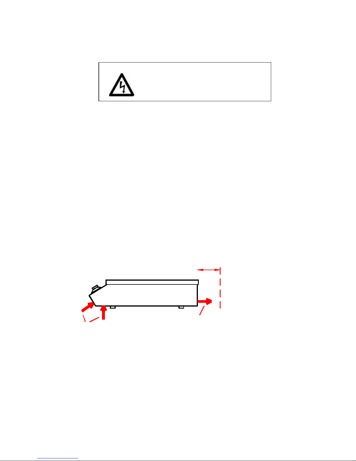
The cooker has to be set up on a even place like a table and requires an area of at least
400 x 480 mm. The air inlet and air outlet may not be obstructed, the place must be able to
withstand a loading of 40 kg. The cooker doesn’t have to be fixed on the table. The control
knob to operate the cooker must be easily accessible.
To guarantee proper operation of the cooker, the ambient temperature must be within the
range of -5º to 40ºC / -40º to 110º and humidity of air between 30% to 90 %
The cooker may not be exposed to jet of water.
Induction cooker, Model ...-Flat
d: minimal distance to the wall = 4 cm
air inlet
side view
air outlet
d
4.1 Pan material for induction cookers
Cooking with induction à it is very important to use appropriate pan material. The bottom of
the pan is the element that closes the magnetic field generated by the induction coil.
Use only appropriate pan material.
In order to check whether your pan is appropriate, use a magnet. This has to stick at the
bottom of the pan. If not, your pan is not suitable for induction cookers. Choose a pan
suitable for induction.
Service-Manual, new version author: Chr. Fuchs 17.06.99 / INDUCS Ltd. 18.09.03 page 8 of 28
5 Tests
5.1 Pan detection (Base-Line only)
ATTENTION The heating area is warmed by the hot pan. In order to
avoid injuries (burnings), do not touch the heating area.
This test shows whether the induction cooker is working well when pans with a little
diameter are used and if little metallic objects are heated on the heating area. To do this
test, you need the following material:
• An appropriate pan with a bottom diameter of 12 cm
or two untreated round metallic plates, approximately 4mm thick:
• metallic plate 1 diameter d = 12 cm
• metallic plate 2 diameter d = 7 cm
Test with pans
Step Action Level Result
1 Put the pan in the middle of the heating
area
1 ..........12 Heat, the indicator lights
2 Push the pan until the edge of the pan is
in the middle of the heating area
1 ..........12 No heating, the indicator
doesn’t light
Test with metallic plates
Step Action Level Result
1 Put the metallic plate in the middle of the
heating area
1 ..........12 Heat, the indicator lights
2 Push the metallic plate until the edge of
the plate is in the middle of the heating
area
1 ..........12 No heating, the indicator
doesn’t light
5.2 Power rating
ATTENTION The heating area is warmed by the hot pan. In order to
avoid injuries (burnings), do not touch the heating area.
This test shows whether the rating may be set by the potentiometer. You need an appropriate pan
(or a Wok-pan for Wok types) with a bottom diameter of >12cm.
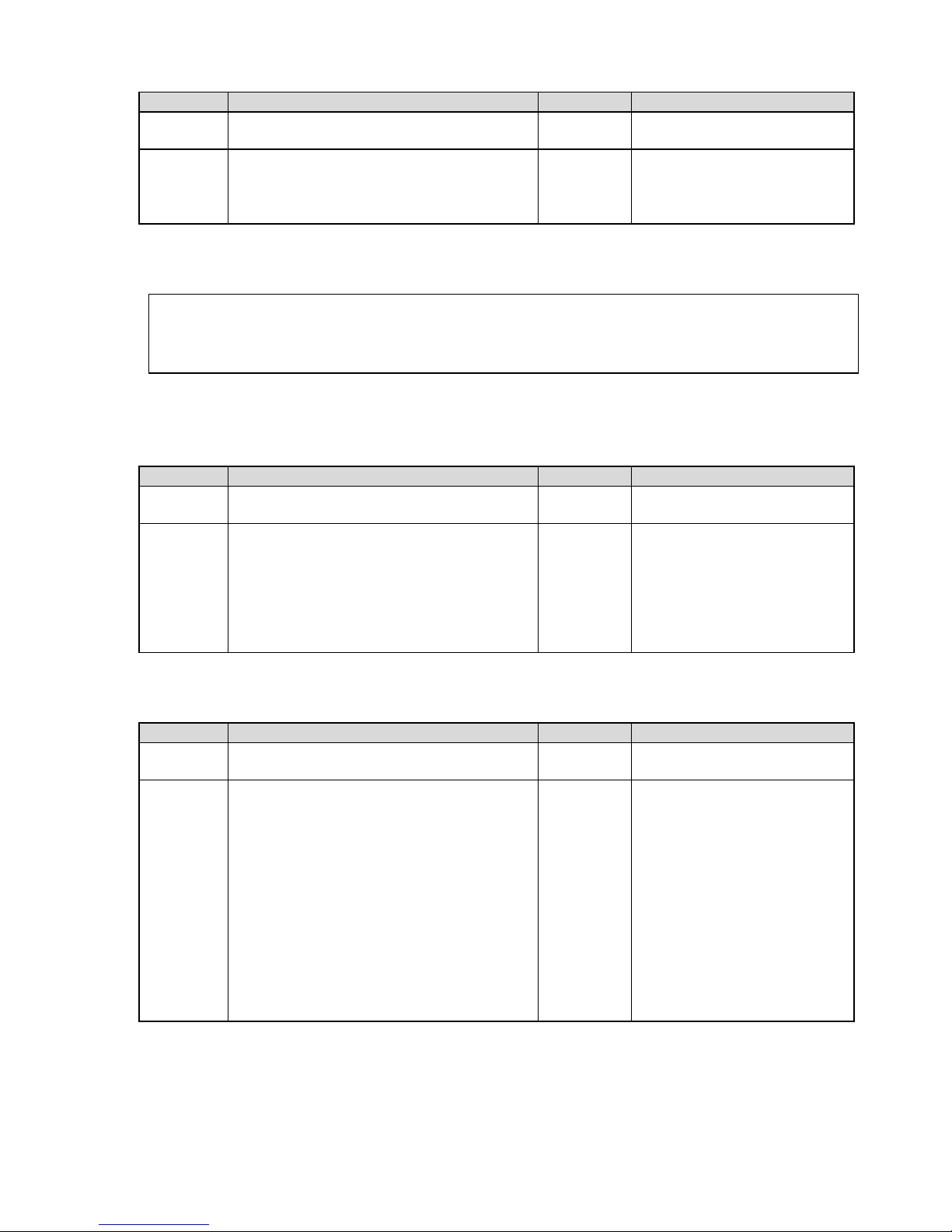
Step Action Level Result
1 Put the pan on the heating area until
water is boiling
12 Heat, water is boiling
2 Reduce the power by turning slowly the
control knob
12 ..........1 Heat rating reduces (water
does not boil anymore),
phase current reduces
continuosly
5.3 Maximum rating
ATTENTION The heating area is warmed by the hot pan. In order to avoid
injuries (burning), do not touch the heating area.
For this test you need a pan with a bottom diameter of 28 cm or more, resp. a Wok pan for the
Wok types.
Test cooking time
Step Action Level Result
1 Put a pan on the heating area and fill it up
with some litres of water (~ 20º)
12 heat
2 Measure the time until water is cooking
(Type Base-Line)
12 The measured time should
be:
140 Sec./litre (3.5kW)
70 Sec./litre (5.0kW)
Measure the time until water is cooking
(Type Wok-Line)
90 Sec /litre (3.5kW)
60 Sec./litre (5.0kW)
5.4 Current
Step Action Level Result
1 Put a pan on the heating area and fill it up
with some litres of water (~ 20º)
12 heat
2 Measure phase current 12 Standard value:
1 x 208 VAC
- 3.5 kW 17A
1 x 220/230 VAC
- 3.5 kW 16 A
3 x 208 VAC
-3.5 kW 10 A
-5.0 kW 14 A
3 x 380/400 VAC
- 5 kW 8 A
 Loading...